Embed Size (px)
Citation preview
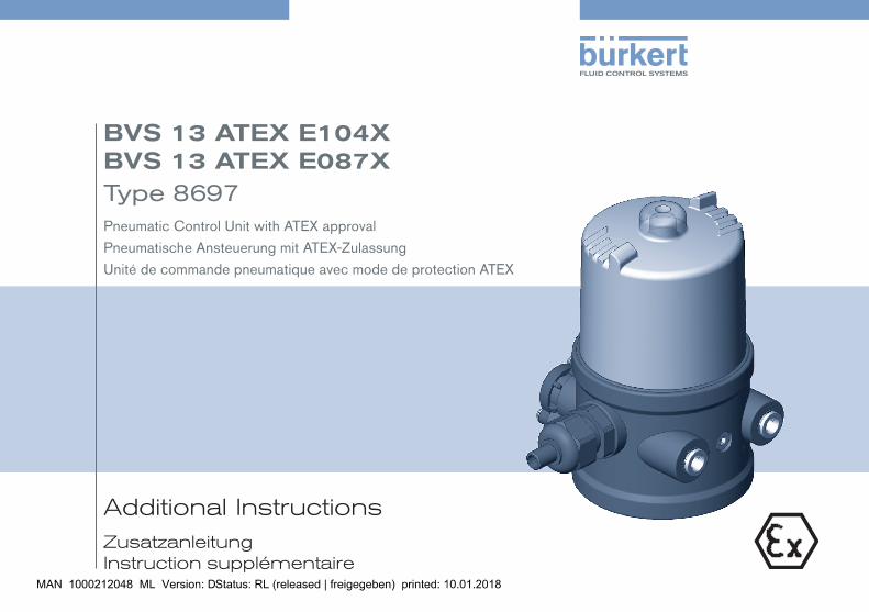
Additional InstructionsZusatzanleitung Instruction supplémentaire
BVS 13 ATEX E104X BVS 13 ATEX E087X Type 8697Pneumatic Control Unit with ATEX approval
Pneumatische Ansteuerung mit ATEX-Zulassung
Unité de commande pneumatique avec mode de protection ATEX
We reserve the right to make technical changes without notice.Technische Änderungen vorbehalten.Sous réserve de modifications techniques.
© Bürkert Werke GmbH & Co. KG, 2012 - 2017
Operating Instructions 1706/02_EU-EN_00810359 / Original DE
3
1 ADDITIONALINSTRUCTIONS...............................................................41.1 Definition of terms / abbreviation ........................................... 4
2 SYMBOLS.........................................................................................................4
3 AUTHORIZEDUSE......................................................................................53.1 Restrictions ................................................................................. 53.2 Identification (V code) Pxxx ..................................................... 5
4 PARTICULARSAFETYINSTRUCTIONS...........................................64.1 Instructions on operation in an explosion-risk (Ex) area ... 74.2 Installation locking wire for PE99 and PX03 ....................104.3 Adaption set - installation note ............................................104.4 Explosion protection approval ..............................................12
TableofContents
BVS 13 ATEX E104X / E087X
English
4
Additionalinstructions
BVS 13 ATEX E104X / E087X
1 ADDITIONAL INSTRUCTIONSThe additional instructions for the use in potentially explosive environ-ments describe the entire life cycle of the device. Keep these instruc-tions in a location which is easily accessible to every user and make these instructions available to every new owner of the device.
Importantsafetyinformation.
Read the additional instructions carefully and thoroughly. Study in particular the chapters entitled Particular safety instructions and Authorized use.
▶ The additional instructions must be read and understood.
The additional instructions describe safety instructions and information for the use of the pneumatic control unit in a potentially explosive environment.
All other descriptions and information can be found in the operating instructions of the device for the Type 8697.
The operating instructions can be found on the Internet at: www.buerkert.com
1.1 Definition of terms / abbreviation
In these instructions, the term "device" always refers to the pneu-matic control unit Type 8697.
In these instructions, the abbreviation "Ex" always refers to "potentially explosive".
2 SYMBOLSThe following symbols are used in these instructions.
DANGER!
Warnsofanimmediatedanger. ▶ Failure to observe the warning will result in a fatal or serious injury.
WARNING!
Warnsofapotentiallydangeroussituation. ▶ Failure to observe the warning may result in a serious or fatal injury.
CAUTION!
Warnsofapossibledanger. ▶ Failure to observe this warning may result in a moderate or minor injury.
NOTE!
Warnsofdamagetoproperty.
Important tips and recommendations.
Refers to information in these instructions or in other documentation.
▶ Designates instructions for risk prevention.
→ Designates a procedure which you must carry out.
English
5
Authorizeduse
BVS 13 ATEX E104X / E087X
3 AUTHORIZED USE
IncorrectuseofthepneumaticcontrolunitType8697canbedangeroustopeople,nearbyequipmentandtheenvironment.
▶ The device is designed to be mounted on pneumatic actuators of process valves for the control of media. The device was designed for the use in - Type8697PX03: Explosion group II, category 3G Ex nA, T4 and explosion group II, category 3D Ex tc, IP65/67, T135°C - Type8697PE99: Explosion group II, category 2G Ex ia, T4 and explosion group II, category 2D Ex ia, IP64, T135°C - Type8697PE51: Explosion group II, category 2G Ex ia, T4 (see information listed on the sticker for the approval).
▶ The device is mounted onto a pneumatic actuator of a process valve. The process valve and the actuator must have at least the Ex approval of the pneumatic control unit.
▶ During use observe the admissible data, the operating condi-tions and conditions of use specified in the contract documents, operating instructions and on the type label - of the pneumatic control unit Type 8697 and - the process valve.
▶ Use the device only in conjunction with third-party devices and components recommended and authorized by Bürkert.
▶ Correct transportation, storage and installation, as well as care-ful use and maintenance are essential for reliable and faultless operation.
▶ Use the device only for its intended purpose.
3.1 Restrictions
If exporting the system/device, observe any existing restrictions.
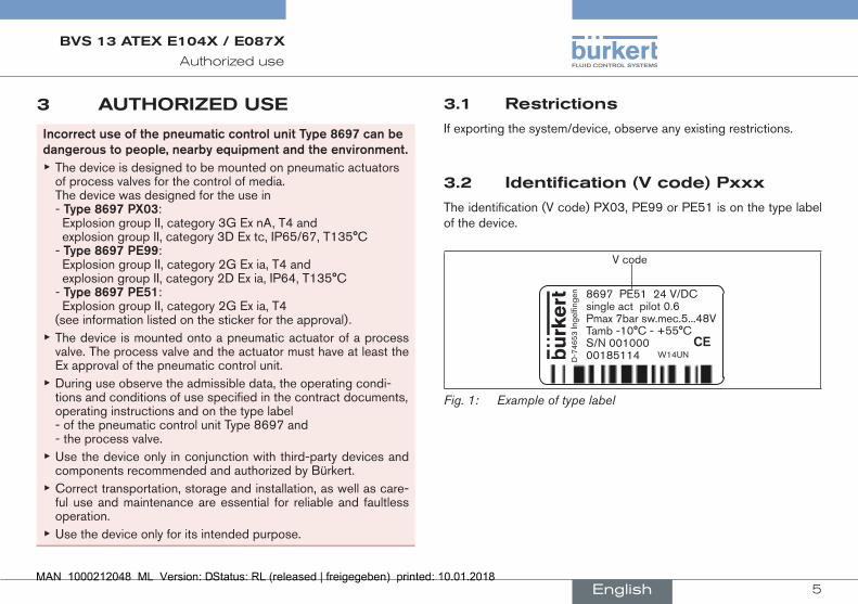
3.2 Identification (V code) Pxxx
The identification (V code) PX03, PE99 or PE51 is on the type label of the device.
8697 PE51 24 V/DC single act pilot 0.6 Pmax 7bar sw.mec.5...48V Tamb -10°C - +55°C S/N 001000 00185114D
-746
53 In
gelfi
ngen
W14UNCE
V code
Fig. 1: Example of type label
English
6
Particularsafetyinstructions
BVS 13 ATEX E104X / E087X
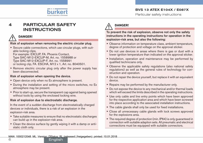
4 PARTICULAR SAFETY INSTRUCTIONS
DANGER!
Riskofexplosionwhenremovingtheelectriccircularplug. ▶ Secure cable connections, which use circular plugs, with suit-able locking clips. For example: EXCLIP, FA. Phoenix Contact, Type SAC-M12-EXCLIP-M, Art. no. 1558988 or Type SAC-M12-EXCLIP-F, Art. no. 1558991 or locking clip, FA. ESCHA, M12 x 1, Art. no. 8040501.
▶ Remove electric circular plug only after the power supply has been disconnected.
Riskofexplosionwhenopeningthedevice. ▶ Open device only when no Ex atmosphere is present. ▶ During the installation and setting of the micro switches, no Ex atmosphere may be present.
▶ Prior to start-up, secure the transparent cap against being opened without tools by using the enclosed locking wire.
Riskofexplosionduetoelectrostaticdischarge.
In the event of a sudden discharge from electrostatically charged devices or individuals, there is a risk of an explosion in the explosion-risk area.
▶ Take suitable measures to ensure that no electrostatic discharges can build up in the explosion-risk area.
▶ Clean the device surface by gently wiping it with a damp or anti-static cloth only.
DANGER!
Topreventtheriskofexplosion,observenotonlythesafetyinstructionsintheoperatinginstructionsforoperationintheexplosion-riskarea,butalsothefollowing:
▶ Observe information on temperature class, ambient temperature, degree of protection and voltage on the approval sticker.
▶ Do not use devices in areas where there is gas or dust with a lower ignition temperature than indicated on the approval sticker.
▶ Installation, operation and maintenance may be performed by qualified technicians only.
▶ Observe the applicable safety regulations (also national safety regulations) as well as the general rules of technology for con-struction and operation.
▶ Do not repair the device yourself, but replace it with an equivalent device.
▶ Repairs may be performed by the manufacturer only. ▶ Do not expose the device to any mechanical and/or thermal loads which will exceed the limits described in the operating instructions.
▶ Use only cable and line entry points which have been approved for the respective application area and which have been screwed into place according to the associated installation instructions.
▶ The cable glands shall only be used for fixed installations. ▶ Close all unnecessary cable glands with lock screws approved for the explosions area.
▶ The required degree of protection (min. IP64) is only guaranteed in connection with suitable adaption sets. All pneumatic and electrical connections must be equipped with suitable connectors.
English
7
Particularsafetyinstructions
BVS 13 ATEX E104X / E087X
4.1 Instructions on operation in an explosion-risk (Ex) area
4.1.1 Safety instructions
For operation in an explosion-risk area zone (gas) 1 and 2, the fol-lowing applies:
DANGER!
Riskofexplosioncausedbyelectrostaticcharge.
In the event of a sudden discharge from electrostatically charged devices or individuals, there is a risk of an explosion in the explosion-risk area.
▶ Take suitable measures to ensure that no electrostatic discharges can build up in the explosion-risk area.
▶ Clean the device surface by gently wiping it with a damp or anti-static cloth only.
4.1.2 Media in explosion-risk areas
If explosive media are used, this can result in additional explosion risks.
4.1.3 Actuators / valves in explosion-risk areas
Use in an explosive atmosphere may be restricted by the actuators / valves. Observe the operating instructions of the actuators / valves.
4.1.4 Cleaning in explosion-risk areas
Check that any cleaning agents are approved for use in explosive atmospheres.
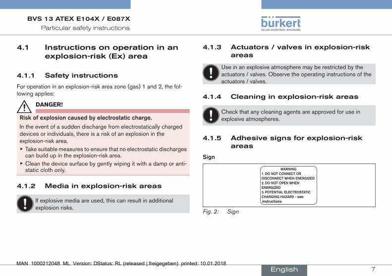
4.1.5 Adhesive signs for explosion-risk areas
Sign
WARNING1.DONOTCONNECTORDISCONNECTWHENENERGIZED2.DONOTOPENWHENENERGIZED3.POTENTIALELECTROSTATICCHARGINGHAZARD-seeinstructions
Fig. 2: Sign
English
8
Particularsafetyinstructions
BVS 13 ATEX E104X / E087X
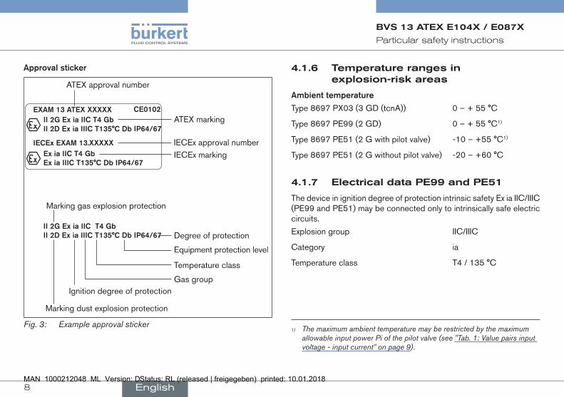
Approvalsticker
ATEX marking
IECEx marking
ATEX approval number
IECEx approval number
II2GExiaIICT4GbII2DExiaIIICT135°CDbIP64/67
IECExEXAM13.XXXXX
EXAM13ATEXXXXXX
ExiaIICT4GbExiaIIICT135°CDbIP64/67
CE0102
II2GExiaIICT4GbII2DExiaIIICT135°CDbIP64/67 Degree of protection
Equipment protection level
Ignition degree of protectionGas group
Temperature class
Marking dust explosion protection
Marking gas explosion protection
Fig. 3: Example approval sticker
4.1.6 Temperature ranges in explosion-risk areas
Ambienttemperature
Type 8697 PX03 (3 GD (tcnA)) 0 – + 55 °C
Type 8697 PE99 (2 GD) 0 – + 55 °C1)
Type 8697 PE51 (2 G with pilot valve) -10 – +55 °C1)
Type 8697 PE51 (2 G without pilot valve) -20 – +60 °C
4.1.7 Electrical data PE99 and PE51
The device in ignition degree of protection intrinsic safety Ex ia IIC/IIIC (PE99 and PE51) may be connected only to intrinsically safe electric circuits.
Explosion group IIC/IIIC
Category ia
Temperature class T4 / 135 °C
1) The maximum ambient temperature may be restricted by the maximum allowable input power Pi of the pilot valve (see "Tab. 1: Value pairs input voltage - input current" on page 9).
English
9
Particularsafetyinstructions
BVS 13 ATEX E104X / E087X
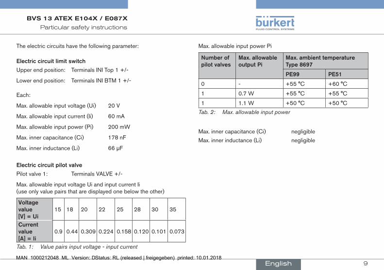
The electric circuits have the following parameter:
Electriccircuitlimitswitch
Upper end position: Terminals INI Top 1 +/-
Lower end position: Terminals INI BTM 1 +/-
Each:
Max. allowable input voltage (Ui) 20 V
Max. allowable input current (Ii) 60 mA
Max. allowable input power (Pi) 200 mW
Max. inner capacitance (Ci) 178 nF
Max. inner inductance (Li) 66 µF
Electriccircuitpilotvalve
Pilot valve 1: Terminals VALVE +/-
Max. allowable input voltage Ui and input current Ii (use only value pairs that are displayed one below the other)
Voltagevalue[V]=Ui
15 18 20 22 25 28 30 35
Currentvalue[A]=Ii
0.9 0.44 0.309 0.224 0.158 0.120 0.101 0.073
Tab. 1: Value pairs input voltage - input current
Max. allowable input power Pi
Numberofpilotvalves
Max.allowableoutputPi
Max.ambienttemperatureType8697
PE99 PE51
0 - +55 °C +60 °C
1 0.7 W +55 °C +55 °C
1 1.1 W +50 °C +50 °C
Tab. 2: Max. allowable input power
Max. inner capacitance (Ci) negligible
Max. inner inductance (Li) negligible
English
10
Particularsafetyinstructions
BVS 13 ATEX E104X / E087X
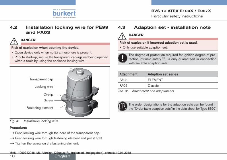
4.2 Installation locking wire for PE99 and PX03
DANGER!
Riskofexplosionwhenopeningthedevice. ▶ Open device only when no Ex atmosphere is present. ▶ Prior to start-up, secure the transparent cap against being opened without tools by using the enclosed locking wire.
Fastening element
Screw
Circlip
Locking wire
Transparent cap
Fig. 4: Installation locking wire
Procedure:
→ Push locking wire through the bore of the transparent cap.
→ Push locking wire through fastening element and pull it tight.
→ Tighten the screw on the fastening element.
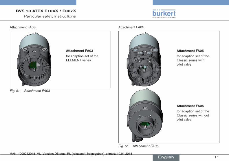
4.3 Adaption set - installation note
DANGER!
Riskofexplosionifincorrectadaptionsetisused. ▶ Only use suitable adaption set.
The degree of protection required for ignition degree of pro-tection intrinsic safety "i", is only guaranteed in connection with suitable adaption sets.
Attachment Adaptionsetseries
FA03 ELEMENT
FA05 Classic
Tab. 3: Attachment and adaption set
The order designations for the adaption sets can be found in the "Order table adaption sets" in the data sheet for Type 8697.
English
11
Particularsafetyinstructions
BVS 13 ATEX E104X / E087X
Attachment FA03
AttachmentFA03
for adaption set of the ELEMENT series
Fig. 5: Attachment FA03
Attachment FA05
AttachmentFA05
for adaption set of the Classic series with pilot valve
AttachmentFA05
for adaption set of the Classic series without pilot valve
Fig. 6: Attachment FA05
English

12
Particularsafetyinstructions
BVS 13 ATEX E104X / E087X
4.4 Explosion protection approval
The explosion protection approval is only valid if you use the modules and components authorized by Bürkert, as described in these oper-ating instructions.
The device Type 8697 may be used only in combination with the valve types released by Bürkert, otherwise the explosion protection approval will be terminated!
If you make unauthorized changes to the system, the modules or com-ponents, the explosion protection approval will also be void.
EC-type examination certificates
BVS 13 ATEX E104X and IECEx BVS 13.0105X,
BVS 13 ATEX E087X and IECEx BVS 13.0097X were issued by
DEKRA EXAM GmbH Dinnendahlstraße 9 D-44809 Bochum
The PTB (CE0102) audits the manufacture.
English
www.burkert.com