Embed Size (px)
Citation preview
OISD GDN-193
First Edition September, 2001
GUIDELINES FOR
GAS LIFT OPERATIONS AND MAINTENANCE
Prepared by
COMMITTEE ON “ GAS LIFT OPERATIONS AND MAINTENANCE ”
OIL INDUSTRY SAFETY DIRECTORATE 7th Floor, New Delhi house
27, Barakhamba Road NEW DELHI – 110 001

NOTE OISD (Oil Industry Safety Directorate) publications are prepared for use in the
Oil and Gas Industry under Ministry of Petroleum & Natural Gas. These are the
property of Ministry of Petroleum & Natural Gas and shall not be reproduced or copied
and loaned or exhibited to others without written consent from OISD.
Though every effort has been made to assure the accuracy and reliability of the
data contained in these documents, OISD hereby expressly disclaims any liability or
responsibility for loss or damage resulting from their use.
These documents are intended to supplement rather than replace the prevailing statutory requirements.
FOREWORD
The Oil Industry in India is more than 100 years old. Because of various collaboration agreements, a variety of international codes, standards and practices have been in vogue. Standardisation in design philosophies and operation and maintenance practices at a national level was hardly in existence. This coupled with feed back from some serious accidents that occurred in the recent past in India and abroad, emphasised the need for the industry to review the existing state- of- the-art in designing, operating and maintaining oil and gas installations. With this in view, the Ministry of Petroleum and Natural Gas in 1986 constituted a Safety Council assisted by the Oil Industry Safety Directorate (OISD) staffed from within the industry in formulating and implementing a series of self regulatory measures aimed at removing obsolescence, standardising and upgrading the existing standards to ensure safe operations. Accordingly, OISD constituted a number of functional committees of experts nominated from the industry to draw up standards and guidelines on various subjects. The present guidelines are prepared by the Functional Committee on“ Gas lift operations and maintenance”. The document is based on the accumulated knowledge and experience of industry members and the various national and international codes and practices. These guidelines are meant to be used as supplement and not as a replacement for existing codes and practices. It is hoped that provisions of guidelines, if implemented objectively, may go a long way to improve the safety and reduce accidents in Oil and Gas Industry. Users are cautioned that no standard can be substitute for the judgement of responsible and experienced Engineers. Suggestions are invited from the users after it is put into practice to improve the document further. Suggestions for amendments to this document should be addressed to the Coordinator, Committee on “Guidelines and recommended Procedures for gas lift operations and maintenance”, Oil Industry Safety Directorate, 7nd Floor, New Delhi House, 27-Barakhamba Road, New Delhi – 110 001.

These guidelines are no way supercedes the statutory requirements of bodies like DGMS, CCE or any other Government Body which shall be followed as applicable.
COMMITTEE MEMBERS
FOR PREPARATION OF GUIDELINES ON
" GAS LIFT OPERATIONS AND MAINTENANCE ''
NAME ORGANISATION POSITION S/SHRI 1. V.V.Manchalwar ONGC LEADER
2. Girdhar Kumar, ONGC MEMBER 3. Gulab Singh, OISD Member-CO-ORDINATOR
CONTENTS S.N. TOPICS PAGE NO. 1. INTRODUCTION 1 2. SCOPE 2 3. DEFINITIONS 2 4. SAFE OPERATING PRACTICES 3 - TRANSPORTATION AND STORAGE - ASSEMBLY AND SERVICING - TESTING AND CALIBRATION
- FACTORS TO BE CONSIDERED BEFORE PUTTING A WELL ON GAS LIFT - LOWERING - UNLOADING
5. REGULAR OPERATION AND MONITORING 10 6. QUALITY OF INJECTION GAS 11 7. LAYOUT OF SURFACE HOOK UP 12 8. WIRELINE OPERATION 13 9. REFERENCES. 14
"GUIDELINES FOR GAS LIFT OPERATIONS AND
MAINTENANCE" 1. INTRODUCTION In the life of an Oil well, Gas Lift operation comes in to picture when the natural pressure energy of the reservoir declines in due course of time. At this stage, it becomes essential to artificially supplement energy in some form to the well fluid to keep the well flowing. There are many methods to artificially lift the well fluid. Prominent among them are Gas Lift, Sucker Rod pumping (SRP), Electrical Submersible pumping (ESP), Hydraulic pumping etc. In off-shore operations, Gas-Lift is the most prominent method of Artificial Lift and in on-shore, it is the second or third most important position in Artificial Lift modes. In Gas Lift operation, high pressure natural gas is injected in to the tubing string at pre-determined depths through either a Gas Lift Valve (GLV) or through a Circulating Valve (CV). High pressure natural gas, when injected in to the tubing, and as the gas expands with decreasing pressure energy from the gas transfer to the well fluid and the fluid column gets lightened and flows up the tubing and finally the well fluid is delivered to the surface hook up. The surface facilities are to be designed and operated in such a fashion as to create minimum back pressure to the fluid flow thus reducing the gas energy consumption to the minimum. In all stages of Gas-lift operations, operator plays an important role. Hence, it is imperative that the operators shall be fully aware of the safe operating practices to be followed in Gas-lift operation. Formulation of these guidelines are a step in the direction to provide adequate safe operating knowledge to the people involved in Gas lift operations. These guidelines are to provide recommended procedures for gas lift operations for ensuring :- · safety of the persons involved in the operations, · safety of the equipment, · safety of the well. · Minimal Environmental Impact.
2. SCOPE
Guidelines covers recommended practices for safe handling, installation and operation of :-
· Gas lift equipment, both surface and sub-surface. · Testing and calibration of the equipment. · High-pressure gas injection lines and flow lines. · Installation, trouble shooting, maintenance operations · Continuous gas lift and intermittent gas lift.
Guidelines covers Gas-lift operations involving use of Casing pressure operated, Nitrogen charged Bellows type valves only.(Different type of gas lift installations are indicated at fig 1 to 2 ) 3. DEFINITIONS · Continuous gas- lift: The process of injecting high pressure gas continuously in to the tubing through Gas lift valve(s). · Intermittent gas-lift : In this type of gas lift operation, injection gas is allowed to pass in to the tubing not on continuous basis at predetermined periodic time intervals for a specified period. · Un-loading: It is defined as the process of displacing the “Kill-Fluid” trapped in the tubing-casing annulus through U-Tubing the fluid through the Gas Lift valves by applying Gas or Air pressure to the annulus till the operating valve is uncovered with fluid. · Wireline retrievable GLV : A Gas lift valve which can be run or retrieved by wireline and is set in a receiving pocket inside a Wireline Retrievable Valve Mandrel (WRVM). · Wireline Retrievable Valve Mandrel (WRVM) : The equipment used to house the GLV in a pocket on the inside of the tubing and having holes in the body to allow gas passage from casing-tubing annulus in to the GLV. The side pocket for housing GLV, protrudes on one side so as to maintain full bore equivalent to tubing inside diameter. It is sometimes also called side pocket mandrel.
· Tubing retrievable Gas Lift valve ( Fig – 3 ) : Gas lift valve which is mounted in the pocket on the outside of the tubing on a Tubing retrievable mandrel. This type of valve can not be retrieved by wireline and tubing has to be pulled out for its retrieval. · Tubing retrievable GLV mandrel : The equipment used to house the GLV in a threaded pocket outside of the body. GLVs are fitted in to the pockets of these mandrels before lowering them in to the well. To retrieve a GLV, these mandrels are to be pulled out along with tubing. · Wireline Operations : Various operations performed in a well using a long continuous length of solid or stranded metal wire and appropriate spooling equipment at the surface with specialised tools attached to the well end of the wire. In gas lift operations, wireline jobs are carried out for the purpose of insertion or retrieval of GLVs, for recording pressure and temperature surveys and also for tagging the fluid levels in the tubing. · Pressure survey : It is a wireline operation in which a pressure recording device is lowered in to the well by wireline and downhole pressures are recorded at different depths in either flowing or shut-in condition of the well. · Temperature Survey It is a wireline operation in which a temperature recording device is lowered in to the well by wireline and downhole temperatures are recorded at different depths in either flowing or shut-in condition of the well. · Probe test
The purpose of the Gas Lift valve Probe test is to determine the relative “stiffness” of a gas lift valve and to determine the maximum stem travel of the stem tip. 4. SAFE OPERATING PRACTICES : 4.1 Equipment handling : 4.1.1 Transportation and Storage : a) GLV : § While transporting GLVs, they should be properly protected against
mechanical damage, preferably packed in a shock proof container.
§ During transportation and storage, threads of the GLV should always be kept properly greased and covered with a thread protector.
§ Tail plug should be in place to avoid accidental damage to the charging pin of the dome.
§ Care should be taken that GLVs are not dropped from height or hit against any objects.
§ The gas passage holes in the GLV should always be covered during transportation and storage, to avoid plugging by foreign material/dust.
§ It should be ensured that calibrated valves should be tagged properly indicating the information of set-pressures, depths and well numbers before either transporting them to the well or sending them for temporary storage.
§ It is to be ensured that the various joints of a charged GLV should be properly tightened before transportation.
b) Mandrel : § Threads should be properly greased and protected by thread protectors
during transportation and storage. § In case of Wireline retrievable valve mandrels, holes in the mandrel should
be covered properly so that no foreign material should enter inside the mandrel and plug the holes as well as damage the polished bore of mandrel.
§ It is advisable to keep a dummy valve in the side pocket during long periods of storage to prevent rusting and corrosion of polished bore portion.
4.1.2 Assembly and Servicing : a) GLV: · Before dismantling the GLV for servicing/ repair, bellow/dome should be
de- pressurized. · Pipe wrench or vice should never be used on the round portion of the GLV
for assembly and dismantling. They should be applied in the grooves provided for the purpose if any. If no grooves are provided on the GLV, then Strap wrench/Parmalee type of wrenches are only to be used for assembling and dismantling.
· Bellows are the most sensitive part of any GLV. So, after dismantling, bellows should be handled with utmost care to avoid physical damage to them.
· In order to prevent deformity to the convolutions of the bellows, bare bellows should never be stretched or bent side ways.
· As Stem and Seat come in pairs, they should always be kept together and different seats and stems should not be mixed.
· Proper depressurising tool to be used to avoid damage / injury to the operator.
· It is to be ensured that the Silicon fluid is not lost while servicing GLV.

b) Mandrel : · Before re-using the pulled out Mandrels from the well, they should be
hydraulically tested to confirm their pressure integrity. · Threads of the Mandrel should also be checked before lowering to avoid
complications later on. 4.1.3 Testing and Calibration : a) Test Site recommendations: The testing facilities necessary to perform gaslift valve testing will require a high pressure, high volume source of Nitrogen gas. Safe recommended practices for the same are as under:- · Local, state and national and international codes and practices should be
followed when constructing the facility. The piping, valves, and surge vessels comprising the gas – lift valve testing system will be subjected to high pressure gas. As such, the fabrication, testing and valve selection should adhere to the established codes governing piping systems and vessels.
· Surge or other vessels with diameters exceeding 6 inches ( 152 mm) should adhere to ANSI / ASME sec VIII DI-89 “ Rules for Construction for Pressure Vessels Division 1” or Sec VIII D2-89 “ Rules for construction of pressure Vessels Division 2 – Alternatives rules”. These rules provide requirement for design, fabrication, inspection, and certification of applicable vessels.
· The piping consisting of materials, wall thickness, and related pressure ratings, should adhere to ANSI / ASMEB31.8-89 "Gas transmission and distribution piping systems” and subsequent addenda. Piping material should be specified as grade B. Flanges should adhere to ANSI/ASME B16.5-88 “ Pipe Flanges and Flanged Fittings” and errata; valves are covered by ANSI/ASME B16.34-88 “ Valves –Flanged , Threaded, and welded End”.
· The design pressure for piping, valves, flanges, or pressure vessels should be at least 20 % greater than the highest working pressure anticipated during the gas lift valve tests.
b) Testing
All the valves shall meet the following requirements. (As followed during manufacturing stage as described in API 11V1.)
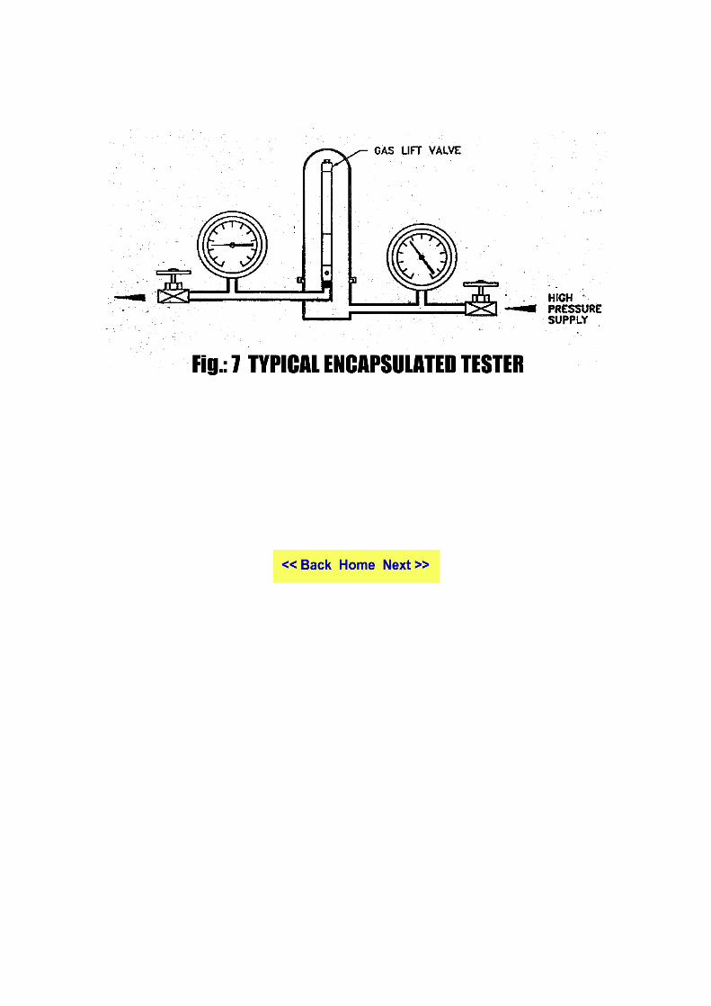
I. The test equipment · Test rack (Fig-4) : This is the equipment used to set the opening and
closing pressure of the gas lift valve. There are two general types in use: The “sleeve tester” and the “ encapsulated” tester. The piping, pressure gauges, connections and joints should follow the standards mentions above.
· Water bath This is water filled container where several gas lift valves are immersed in the
water to bring them to some pre-determined controlled temperature. This device is absolutely essential for pressure charged gas lift valves. Most gas lift installations calculate the gas lift set pressure at 60 degree F, thus the temperature of the water-bath is usually controlled to 60 degree F. If the water temperature is other than 60 degree F, then the pressure used for setting the gas lift valves should be corrected for the temperature of the water bath.. · Pressure chamber or Ager This device is a water filled chamber capable of at least 5000 psig. The gas lift
valves are inserted into the chamber and subjected to a predetermined external pressure for some predetermined length of time and number of cycles. The aging chamber used for this purpose has heavy cap. Proper provision should be made to lift with some mechanism such as chain pulley block etc. otherwise it may lead to an injury to the persons handling it due to sudden fall of the cap.
- Proper care should be taken while pressurising / depressurising the chamber to avoid any damage / injury to the equipment operator.
· Probe This device is a micrometer to measure the stem travel as pressure is applied to the bellows. A continuity tester determines when the rod touches the valve stem.. the rod of the probe is insulated electrically from the valve. The equipment should have following : - A means to control the pressure applied to the gas lift valve sleeve. - The stem position measurement method should be capable of
determining the stem position within +/- 0.005 inches. - The gauges used measure pressure should have an accuracy such that
measurement errors are no greater than +/- 0.255 of the value. - The rod of the probe micrometer should be smoothly tightened to avoid
slippage, which may indicate wrong readings. - Care should be taken to avoid bending of the probe rod and trapping of
high pressure gas between the Teflon gaskets. - The probe set up must be completely leak proof.
· Flow test system The flow test system should include following items.
- Test specimen - Test section - Throttling control valve - Pressure surge tanks - Flow measuring device - Pressure taps - Temperature sensors - Equalizing control valves - Production run tests II. All the valves shall successfully meet the following requirements. · Bellow Assembly test:
Each bellow assembly shall be tested in accordance with B.3 in Appendix B of the API 11V1.
· Valve setting : Each gas lift valve shall be set and pressure tested in accordance with
section B.3 in appendix B of API 11V1. Following safety precautions should be taken during this operation:-
- Entire set up should be tested for no leakage with dummy valve in place. - The system should be fully depressurized before inserting or taking out the
valve in the test fixture. - It should be ensured that valve is properly inserted in the test fixture and is
properly secured in the groove. Popping up of the valve may lead to an accident.
· Stem-seat Leakage test( Fig-5) :
Each gas lift valve shall be tested for leakage across the stem and seat in accordance with B.4 in appendix B of API 11V1. The leak shall not exceed 35 scft/d when the downstream pressure on the valve is zero and the upstream pressure on the valve is greater than Pvct with the valve in fixture. Pvct is test rack opening pressure at ambient temperature. The safety precautions as mentioned above should be adhered to in this test also. · Reverse flow valve leakage test: Reverse flow valve shall be tested with air, nitrogen, helium, or other compressed gas for leakage in accordance with the manufacturer’s specifications. The leak shall not exceed 35 scft/day with a 100 +/- 10 % psi differential pressure. The safety precautions as mentioned in appendix B above should be adhered to.
· Bellow stabilisation test:
Each gas lift valve after setting shall be subjected to aging in accordance with section B.4 in appendix B of API 11V1.Following safety precautions should be taken during the test: § Tail plug shall be installed on the gas lift valve prior to putting it in the
aging chamber. § The test set up with all the piping shall be pressure tested to at least 20 %
excess of the pressure to which the test is to be conducted. § The aging chamber used for this purpose has heavy cap. Proper provision
should be made to lift the cap. § Every time the cap is to be taken out, it should be ensured that the system is
depressurized fully. § After every aging the valve has to be put in water bath for temperature
stabilization prior to testing change in the setting of the valve. · Probe test( Fig-6)
§ Prior to starting testing all the lines should be properly anchored and secured
for safety. § The test set up should be pressure tested with dummy valve in place for
pressure integrity of the test set up. 4.2 Factors to be ensured before putting a well on gas lift : § While selecting a well to be put on gas lift, pressure integrity of production
casing shall be ascertained and ensured to prevent the gas injection pressure being communicated to the outer annuli during continued exposure of casing to the injection pressure.
§ The checking of the integrity of the primary and secondary seals and the proper cement rise behind the casing can prevent the communication between the production casing and the outer casings.
§ There should be a schedule of regular checking of the communication between the outer casings and the production casings.
§ If any communication is observed between the production casing and outer annuli, suitable remedial measures should be taken to stop communication so that injection gas pressure is not communicated to the outer annuli. This is to avoid any leakage of gas and ultimate blow out situation.
§ In such situations, where the gas injection pressure is getting communicated to the outer casings from the production casing, a proper mechanism has to be installed so that the outer annuli can be automatically bleed off. Such wells should be kept under high alert level and should be repaired at the earliest.
§ Gas Composition of the injection gas is of prime importance for the
corrosion effect on the casing, specially in case of carbon dioxide and hydrogen sulfide in presence of water. For details of permissible limits of partial pressure of CO2 and H2S to avoid/minimize corrosion, relevant API specifications should be referred.
4.3 Lowering : § If the GLVs are being lowered along with Mandrels, sequence of the
Mandrels, serial wise and depth should be clearly marked on the Mandrels. § While inserting the GLV in side pocket mandrel , excessive force should not
be applied which may cause problems during subsequent retrieval by wireline.
§ After inserting the GLV in to the pocket and before lowering the Mandrel, they are to be hydro tested to ensure pressure integrity.
§ In the case of tubing retreavable conventional mandrel, ensure that the GLV is guarded by the protector to avoid damage to the GLV by friction / abrasion with the casing valves while lowering the valves.
4.4 Un-loading : § Maximum damage to GLV’s occurs during un-loading operation. Hence,
utmost care should be taken for proper and safe un-loading of Gas Lift well. § Unloading of the well is the first operation in a gas lift well. Subdued fluid
from the casing is U-tube into tubing through gas lift valves by applying air / gas pressure in the annulus.
§ Recommended procedures as per API RP 11 V5 should be followed while unloading a gas lift well.
§ Large quantities of gas released during unloading operations is generally piped away from the installation and flared.
4.4.1 Onshore Operations: § If the well is unloaded into the pit, all the joints in the temporary flow line
from well to pit shall be properly tightened. § Temporary flow line shall be anchored properly to avoid any accident in
case of sudden jerking of the line caused by flow of gas. § No un-authorised person should be allowed in the area. § A bend should be fitted to the end of pipe line so that flow is always
directed downward into the pit.. § If the well is to be unloaded through the permanent flow line connected to
installation, concerned Incharge/Shift Incharge shall be informed
beforehand to avoid upset in process in the separation / liquid handling facilities
4.4.2 Offshore Operations § If the unloading is not done into the regular system then the discharge from
the well should be diverted into burner / sea. § While discharging the initial subdued fluid into sea, care should be taken to
divert the flow to burner, as soon as oil/gas surfaces. § Depending on the wind direction suitable burner either on star board side or
port side shall be chosen so as to avoid the flow of gas / heat towards the rig.
§ For the rig safety, adequate cooling water is to be sprayed towards the flame so that heat is effectively dissipated .
§ The temporary line connection used to divert the well fluid to the sea/burner, shall be pressure tested, tightened properly and anchored.
§ High liquid velocities occurring at GLV’s in case of a fast un-loading causes abrasion/cutting of GLV seat, thus the valve becomes defective and will pass gas during GL operation. To avoid damage to GLV and upsets in surface facilities, proper unloading procedures as per section III-1 of API RP 11 V5 to be followed.
5. Regular operation and monitoring: A gas lift installation is usually unmanned and main hazard is that due to fire, the other hazard being the failure of pipeline or control valves due to high pressure. Standard check list shall be prepared to check following : - § In live and pressure charged lines/flow arms, no operational adjustments
should be carried out unless that portion of the line/flow arm is isolated from both upstream and downstream sides and pressure is bleed-off through cock valve/bleed valve. Before putting into operation , all bleed/cock valves should be closed.
§ Two/three pen recordings are very common monitoring tools in gas lift operations. When connecting and disconnecting the pen recorders, special care should be taken to isolate the connecting tube to recorders/sensors and pressure bleed off.
§ Flammable oil and gas are constantly present at the gas lift installation and unless sources of ignition like naked lights, frictional sparks, electrical sparks, static electric charges, lighting overheated surfaces, are carefully controlled, fire could be a major hazard. In some cases, even auto-ignition takes places.
§ No welding or cutting job should be allowed near the well while the well is
in operation. If such jobs are unavoidable, then well shall be closed and source of injection gas should be cut-off and all the lines near the wellhead area are to be de pressurized. OISD standard 105 may be refereed and permit shall be issued as per standard.
§ Every person permitted to enter the production installation, if carrying any smoking item cigarettes and matches shall be deposited at the gate. Suitable notice to this effect should be prominently displayed at the gate
§ Injection gas shall be dehydrated properly before its entry into the gas injection network to avoid corrosion and hydrate formation.
§ No smoking board and pictorials should be displayed. § Hammers and other handling tools made of Brass should only be used for
undertaking any mechanical work involved on the injection gas lines. § The pressure and DP recorders of two / three pens recording assembly
should be periodically calibrated to avoid errors in readings. § The air / gas used for the control instruments should be dry to avoid
malfunctioning. 6. Quality of injection gas ; § All the high pressure components should be hydrotested once in two years
in corrosive atmosphere and once in three years in normal atmosphere. Surface condition of these equipment also should be maintained in good condition by regular surface preparation and painting. Furthermore, periodical corrosion studies should be carried out to compare data against base data to find out any decrease in thickness.
§ The safety valves, pressure gauges, flanges & extra tapings, shutdown valves need regular checks for any hydrocarbon leakage. In case of any leakage, it should be immediately rectified.
§ As the gas lift installation involves high pressure valves and other components at the wellhead, it is recommended that all the gas lift wells should be fenced upto 15 meters from the well head area to restrict the access to un authorised persons and straying of animals towards the well site.
§ The material guidelines for metals and elastomers for the gas lift valves and other sub surface equipment are indicated in API spec 11V1, section.4. For the initial installation in a H2S environment, the equipment should comply with NACE-specification. .
§ It should be ensured that , as far as possible, the injection gas should not contain corrosive gases like H2S and CO2. But if injection gas contains some quantity of H2S and CO2, then all the flow lines and valves in the line injection gas passage should be of suitable material.
§ If the injection gas contains some quantity of corrosive gases, then a proper
strategy should be adopted to prevent corrosion to the casing. Either gas should be injected through another concentric string (Not through casing), or alternately some corrosion inhibitor should be injected along with injection gas if, gas is injected through casing.
7. Lay out of surface hook up:
Lay out of gas injection line hook up is to be made keeping the following factors in mind,
§ A clear access shall be available for the movement of rig, wireline winch and minimum hindrance to carry out any work over job on the well.
§ No tapping should exist upstream of the main isolation valve. § Minimum required number of tapings should be provided in the hook up to
the well. § All the valves and tapings should be of suitable pressure rating to match the
expected pressures in the line. § Number of bends in the line hook up should be kept to minimum and sharp
bends should be avoided as far as possible. § It shall be ensured that valve is provided on both sides of the annulus to
facilitate de pressurizing of the annulus. Bull plug with flange should not be used in casing spools.
§ A non-return valve should be installed immediately after the annulus valve for preventing the back-flow of well fluids in to the gas injection line network.
§ For Off shore operations, a shut down valve on the gas injection line as well as on the production flow arm is required to be installed for emergency shut down purposes.
§ Surface line should be hook up with proper engineering drawing. § Injection gas lines should be pigable. § Undulations in elevation should be avoided as far as possible because liquid
accumulation will take place in low points which in turn will become potential spots for increased corrosion.
§ Corrosion monitoring of injection lines should be carried out periodically to identify trouble spots to initiate timely action.
§ As a good house keeping measure, all the high pressure instrument lines leading to two/three pin recorder should be laid and maintained in a systematic way and secured properly.
§ All temporary lines used during well activation should be removed and replaced as quickly as possible. All the gas injection as well as well fluid lines should be properly designed and should be permanent.
8. Wireline operations : In gas lift operations, wire line operation is frequently used either to retrieve and replace the GLV, to record the bottomhole pressure/ Temperature, and to tag the fluid level. 8.1 General : § Before undertaking any wire line operation, functioning of the Christmas
Tree valves is to be checked and ensured for full closure and opening. § Sub surface safety valves (SSSV) should be checked for proper functioning. § It should be ensured that lubricator stuffing box packing are in good
condition to prevent leakage of well fluids in to the atmosphere. § Lubricator, along with stuffing box shall be pressure tested in the shop prior
to usage in the well. § For preventing fall of personnel while fitting lubricator or lowering the
tools, proper arrangement should be provided for the safety. § Wireline operations should be carried out as per recommended procedures. 8.2 Gas lift valve insertion and retrieval : § Gas lift valves can be inserted or retrieved from the mandrels in the well by
wireline operation when side pocket type mandrels are used. § In order to ensure smooth passage of the GLV and tools in to the well,
tubing clearance should be checked and ensured by dummy run along scrapper prior to the lowering of the GLV with tool.
§ To prevent the blowing up of the tool, pressures in the tubing and annulus should be equalised before de-plugging GLV from any mandrel.
8.3 Pressure and temperature surveys :
Flowing pressure and temperature surveys are one of the important diagnostic tools for analysing the performance of any gas lift operation.
A pressure recording instrument is lowered into the well and bottom hole flowing pressures are recorded either at selected valve depths or at specific intervals. Such pressure data will give indication of the point where gas is to be injected , tubing loads at different points etc. a) Continuous Gas Lift:
Unless the gas flow rate is very high in tubing, chances of instrument blowing up the hole are very less. However, it may be safe to attach some weight bars to the string where gas flow rates are very high, then a ‘no-blow’ device should be attached below the instrument in addition to the weight bars. b) Intermittent Gas Lift:
Chances of the instrument being blown up the hole are high while
lowering the instrument in intermittent gas lift well. So, either the gas injection shall be stopped while lowering the instrument or when the instrument is being lowered in flowing condition, sinker bars should be added above the instrument and also ‘no blow’ device should be used along with the instrument. ‘No blow’ device is useful in preventing the instrument being blown up the hole because any upward movement of the device will activate the upward slips in the device which will clutch to the tubing walls and prevent the string from being blown up the hole. Recording should be in stabilized condition only. Preferably, well testing should be carried out during Pressure/Temperature survey. 9. A suitable pocket guide should be made available to the operator for ready reference. Operators should be given hand on training before deploying them on actual job for avoiding accidents.
10. References:-
§ API Standard 11 V 1 to 5 § OISD standard 105..
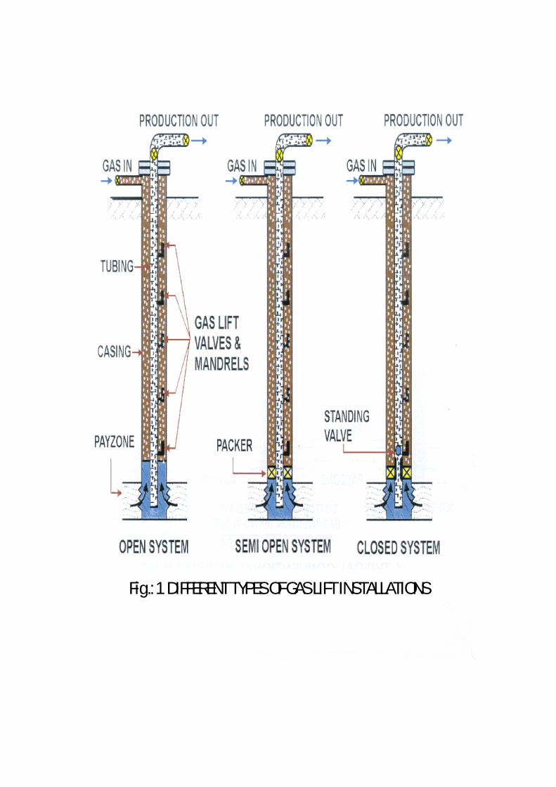
Fig.: 1 DIFFERENT TYPES OF GAS LIFT INSTALLATIONS


Fig.: 2 CASING PRESSURE OPERATED GAS LIFT VALVEWITH CONVENTIONAL MANDREL


Fig.: 3 GAS LIFT VALVE
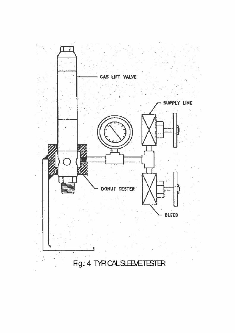
Fig.: 4 TYPICAL SLEEVE TESTER
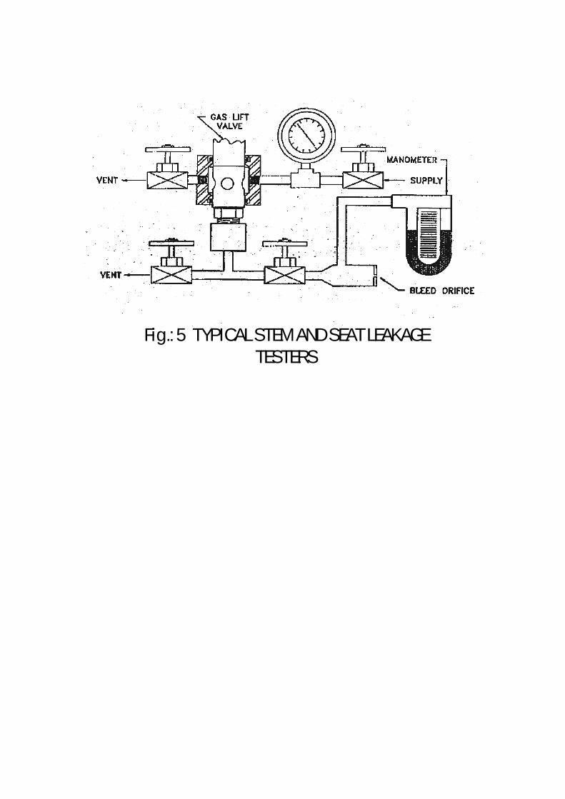
Fig.: 5 TYPICAL STEM AND SEAT LEAKAGETESTERS
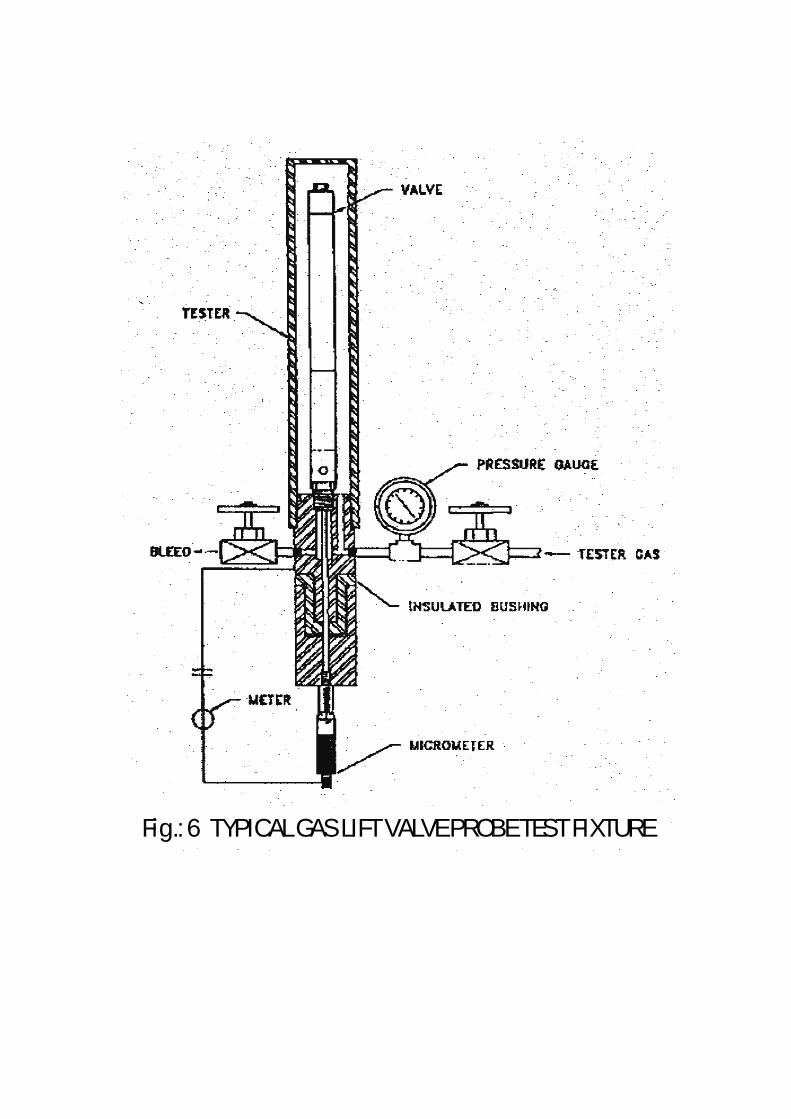
Fig.: 6 TYPICAL GAS LIFT VALVE PROBE TEST FIXTURE