Embed Size (px)
Citation preview

Nuova Strada di Piano PPR 20099 Sesto San Giovanni (MI), Italy
Tel. +39 02 24 10 50 01 www.alstom.com
IS 2470 GB Page 1 of 15
Property of ALSTOM GRID This document and any information therein contained are proprietary and confidential and must not be distributed, published, or more generally disclosed for any purpose whatsoever. Effectivity of paper copy should be checked prior to use.
OIL-TO-OIL BUSHINGS SERIES PNO VOLTAGE FROM 245 kV TO 765 kV
STORAGE, OPERATING
AND MAINTENANCE INSTRUCTIONS

OIL-TO-AIR BUSHINGS SERIES PNO VOLTAGE FROM 52 TO 245 kV IS 2470 GB
Page 2 of 9 Istruction Manual Rev. H – March 2015
INDEX
1 DESCRIPTION ............................................................................................................................................3 1.1 GENERAL ............................................................................................................................................3 1.2 SAFETY ...............................................................................................................................................3 1.3 TECHNICAL CHARACTERISTICS ......................................................................................................3
2 PACKING AND STORAGE .........................................................................................................................5 2.1 PACKING .............................................................................................................................................5 2.2 ACCEPTANCE .....................................................................................................................................5 2.3 STORAGE ............................................................................................................................................6
3 LIFTING AND TRANSPORTATION ...........................................................................................................6 3.1 PACKED BUSHING .............................................................................................................................6 3.2 UNPACKED BUSHING ........................................................................................................................6 3.3 SHIPMENT TO THE END USER ..........................................................................................................7
4 INSTALLATION ON THE TRANSFORMER ...............................................................................................7 4.1 DRAW LEAD CONNECTION ...............................................................................................................7 4.2 DRAW ROD CONNECTION ................................................................................................................8 4.3 BOTTOM CONNECTION .....................................................................................................................8 4.4 OIL SIDE SHIELD ...............................................................................................................................10 4.5 ICE AND SNOW DEPOSITS ..............................................................................................................10 4.6 OIL FILLING OF THE TUBE OF THE BUSHING................................................................................10 4.7 OIL LEVEL REGULATION .................................................................................................................10 4.8 CONNECTION TO BUCHHOLZ RELAY ............................................................................................11
5 TEMPERATURE LIMITS ..........................................................................................................................11
6 SERVICE AND MAINTENANCE ...............................................................................................................11 6.1 PAINTING ..........................................................................................................................................11 6.2 CHECKS AFTER INSTALLATION .....................................................................................................11 6.3 DISASSEMBLY OF THE BUSHING ...................................................................................................12 6.4 MAINTENANCE .................................................................................................................................12 6.5 MEASUREMENT OF DIELECTRIC LOSSES ....................................................................................13 6.6 CHECKS ON OLD BUSHINGS ..........................................................................................................13 6.7 EXTRAORDINARY CHECKS .............................................................................................................14 6.8 OIL SAMPLING ..................................................................................................................................14
7 DISPOSAL AT THE END OF LIFETIME ..................................................................................................15
Revision H March 2015 Revision G Maj 2012 Revision F October 2010
OIL-TO-AIR BUSHINGS SERIES PNO VOLTAGE FROM 52 TO 245 kV IS 2470 GB
Page 3 of 9 Istruction Manual Rev. H – March 2015 1 DESCRIPTION 1.1 GENERAL
These instructions are applicable to the OIP (oil-paper) condenser bushings of series
“PNO” - Rated voltage 800 kV
according to IEC 60137 Standard “Insulated bushings for alternating voltages above 1000 V”, and give all general information to be followed from the receipt of bushings until their installation on the transformer. Other information are given regarding their service and maintenance.
Design, components and manufacturing technology guarantee an average lifetime longer than 30 years, in normal operation conditions.
The designation of the bushing is made as in the following example:
PNO.800.525.800 P Condenser bushing (“P” from Italian word “Passante”) N Normal tail type, oil to air O Oil paper insulation (OIP) 525 Rated voltage (in kV) 1550 BIL – Basic Insulation Level (in kV) 1250 Rated current (in A) 1.2 SAFETY
This manual must be available to the personnel responsible of the installation, operation and maintenance of the bushings.
The installation, operation and maintenance of the bushings present conditions of no safety and it is necessary to follow carefully specific procedures and instructions. No compliance with these procedures and instructions can involve very severe and dangerous conditions for the personnel and the property.
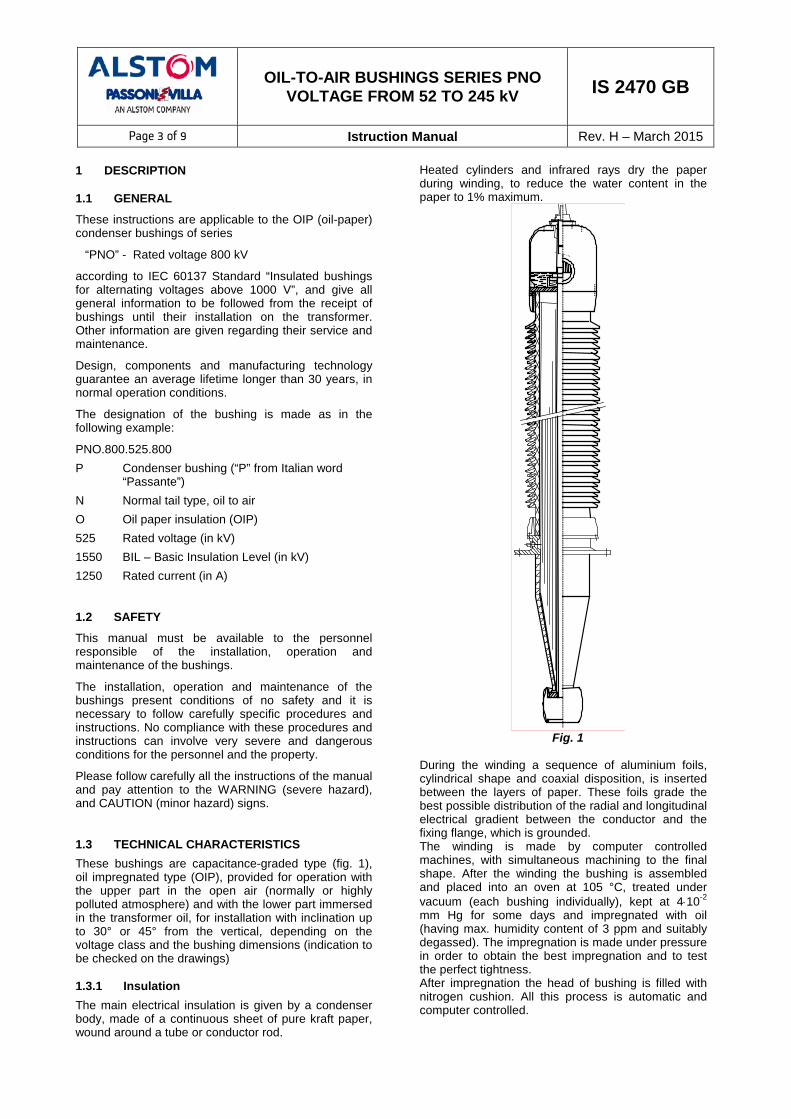
Please follow carefully all the instructions of the manual and pay attention to the WARNING (severe hazard), and CAUTION (minor hazard) signs. 1.3 TECHNICAL CHARACTERISTICS These bushings are capacitance-graded type (fig. 1), oil impregnated type (OIP), provided for operation with the upper part in the open air (normally or highly polluted atmosphere) and with the lower part immersed in the transformer oil, for installation with inclination up to 30° or 45° from the vertical, depending on the voltage class and the bushing dimensions (indication to be checked on the drawings) 1.3.1 Insulation The main electrical insulation is given by a condenser body, made of a continuous sheet of pure kraft paper, wound around a tube or conductor rod.
Heated cylinders and infrared rays dry the paper during winding, to reduce the water content in the paper to 1% maximum.
Fig. 1
During the winding a sequence of aluminium foils, cylindrical shape and coaxial disposition, is inserted between the layers of paper. These foils grade the best possible distribution of the radial and longitudinal electrical gradient between the conductor and the fixing flange, which is grounded. The winding is made by computer controlled machines, with simultaneous machining to the final shape. After the winding the bushing is assembled and placed into an oven at 105 °C, treated under vacuum (each bushing individually), kept at 4⋅10-2 mm Hg for some days and impregnated with oil (having max. humidity content of 3 ppm and suitably degassed). The impregnation is made under pressure in order to obtain the best impregnation and to test the perfect tightness. After impregnation the head of bushing is filled with nitrogen cushion. All this process is automatic and computer controlled.
OIL-TO-AIR BUSHINGS SERIES PNO VOLTAGE FROM 52 TO 245 kV IS 2470 GB
Page 4 of 9 Istruction Manual Rev. H – March 2015 1.3.2 Air side The air side envelope is made of porcelain, brown colour (upon request grey colour or resin fibre-glass envelope covered with silicone sheds), with a creepage distance normally for very high-polluted atmosphere (VHP): 31 mm/kV. The shed configuration is alternated type (small-large sheds). This is the most effective solution as proved by salt tests and the profile of sheds complies with the recommendations of Standards. More pieces of porcelain are used, epoxy resin glued, without using gaskets in between. 1.3.3 Oil side The oil side envelope is made of moulded epoxy resin for bushings up to 420 kV. This type of housing has been employed by Alstom Grid Spa – Rpv for the first time in 1963, for the manufacturing of the transformer side envelope in the re-entrant type bushing. The epoxy resin is bi-components type, i.e. consists of a resin base and a hardener, the charge material is quartz sand. The epoxy resin envelopes have shapes, thickness and dimension tolerance not possible to be achieved by porcelains, moreover they can grant the possibility of making metal parts embedded in the mass itself. For bushings greater than 420 kV the oil side envelope is made of one piece porcelain. Versions with under flange sleeve in oil side for CT accommodation are available upon request. 1.3.4. HV terminal The HV terminal can be removable in case of draw lead or draw rod execution; it is coupled to the conductor by means of multi-blades contacts, and it is fixed on the head by means of four screws. In case of bottom connection execution it is fixed. Terminal can be made of aluminium or copper, depending from the rated current of the bushing; the aluminium one can be without any surface treatment or silver plated; the copper one is always tinned. 1.3.5. Head and oil level indication The metal components of the head are made of aluminium alloy casting and acts as oil reservoir. The bushing head operates as oil compensator and is provided by an oil level indicator, prismatic glass type. 1.3.6. Oil side shield The oil side is shielded by a suitable electrode, made of aluminium sheet, with the function of reducing the dielectric strength in oil. The shield is removable in order to ease the lead connection operations. 1.3.7. Flange The flange made of aluminium casting and is equipped with the following accessories:
- Power factor tap; - Buchholz relay connection; - Oil sampling valve;
- Lifting holes; - Potential device tap (voltage tap) – on request.
1.3.8. Gaskets Made of Fluorcarbonium elastomer, o-ring type. They are compatible with impregnating oil of bushing and hot mineral oil of the transformer. Flat gaskets are fitted concentrically to o-rings, to prevent a direct contact from the metal parts and the porcelain envelope. For special requirements regarding low ambient temperatures (up to -60°C) special o-rings are foreseen, made of fluor silicon mixtures. 1.3.9. Assembling Mechanical coupling among all the components is obtained by compression springs placed at the head of the bushing. Furthermore the air side porcelain is cemented to the flange, in order to have a stronger mechanical resistance. The cemented used is a monocalcic aluminized type, curing quick. All the cement surfaces in contact with the external ambient are protected by means of a silicone sealing. 1.3.10. Type of dielectric The impregnation is made with a top quality inhibited super grade mineral oil, fully complying to Standards IEC 60296 and ASTM D3487, with the following outstanding characteristics:
• High dielectric strength (>70 kV/2,5mm); • Very good low temperature properties (pour
point typically <-60°C); • Low viscosity even at the lowest temperatures; • Very good oxidation stability; • Extremely good heat transfer.
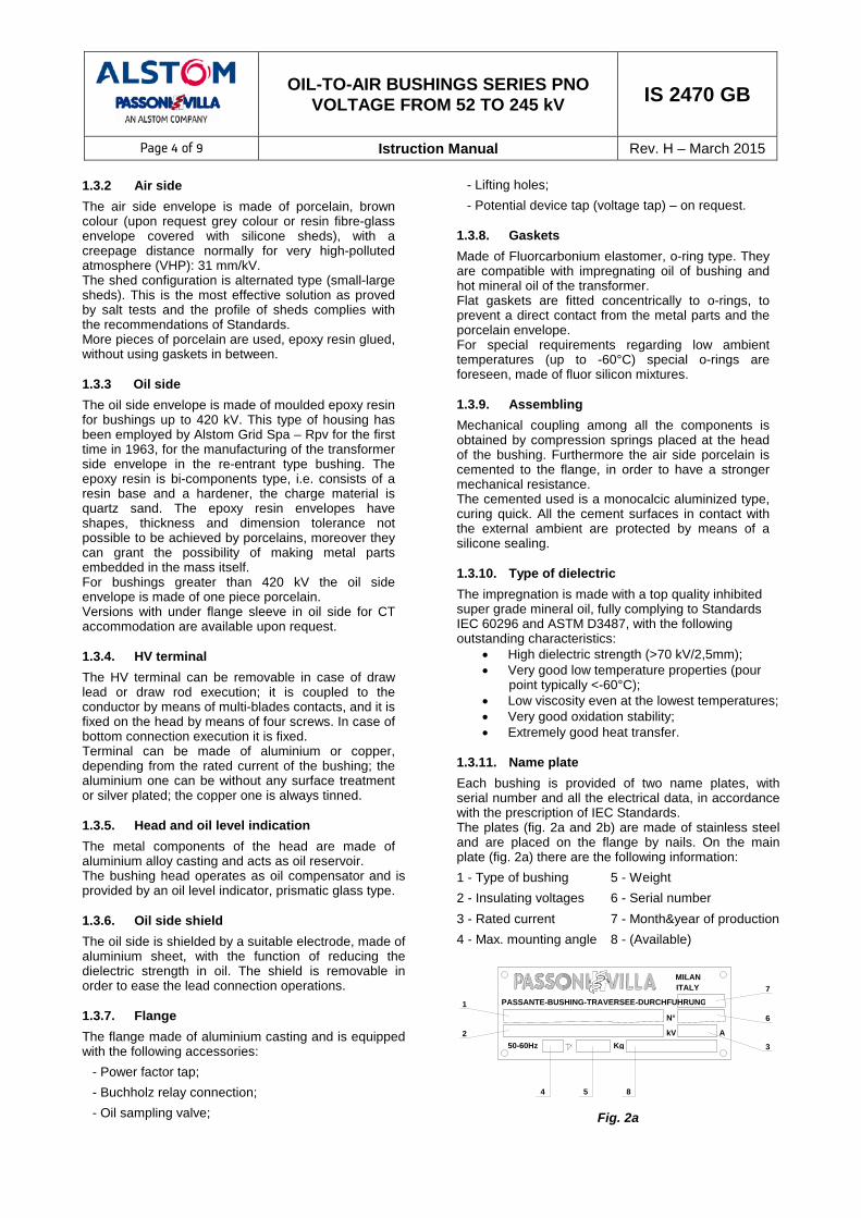
1.3.11. Name plate Each bushing is provided of two name plates, with serial number and all the electrical data, in accordance with the prescription of IEC Standards. The plates (fig. 2a and 2b) are made of stainless steel and are placed on the flange by nails. On the main plate (fig. 2a) there are the following information: 1 - Type of bushing 5 - Weight 2 - Insulating voltages 6 - Serial number 3 - Rated current 7 - Month&year of production 4 - Max. mounting angle 8 - (Available)
50-60Hz
ITALY
PASSANTE-BUSHING-TRAVERSEE-DURCHFUHRUNG
MILAN
KgkV
N°
A
1
2
7
6
3
4 5 8
Fig. 2a

OIL-TO-AIR BUSHINGS SERIES PNO VOLTAGE FROM 52 TO 245 kV IS 2470 GB
Page 5 of 9 Istruction Manual Rev. H – March 2015 The month is indicated by a code, as follows:
A = January L = July B = February M = August C = March P = September D = April R = October E = May S = November H = June T = December On the second plate, there are the following information (fig. 2b) – Serial number – Main capacitance measured value – Tap capacitance measured value – Dissipation factor measured value – Standard reference – Available
Fig. 2b
2 PACKING AND STORAGE 2.1 PACKING
After the tests, before packing, the lower part of the bushing is cleaned from the oil and the porcelain from the dust. Thanks to a special device to prevent the diffusion of the nitrogen cushion of the head into the bottom part, bushings can be packed in horizontal position. Remember to lay down the bushing following carefully the indication of the yellow label glued in the bushing’s head. The possibility of positioning bushings in horizontal grants that the dimensions of cases, containing one bushing, are smaller and the transportation less costly.
CAUTION
When the bushing is positioned in horizontal position, make sure to follow the indications written in the yellow label of fig. 3, positioned on the head: the bushing has to be positioned with the oil level indicator towards the bottom.
2.2 ACCEPTANCE
Upon receipt of the goods the Customer should operate as follows: • Check the external surfaces of the packing cases:
- No sign of damage have to be found;
Fig. 3
- The shockwatch indicator, placed in the external
part of each packing case (fig. 4), must be white. • If the shock watch indicator is red don’t refuse
shipment, make a notation on delivery receipt and inspect for damage as follow: - Open the packing case by removing its cover; - Make sure that the anchoring elements are in
order and securely fixed; - Make sure that there are no leaks from the
bushings, especially in the joints between porcelain and metal parts and that there are no breaks or broken parts. Please consider that each bushing has been tested with the tail immersed in oil, therefore some oil traces can be found.
Fig. 4
• In case any damage is found, leave in original packaging and request an immediate inspection from carrier within 15 days of delivery. Moreover give the forwarding agent a written claim and notify Alstom Grid Spa – Unit RPV with the details of the packing list, including the number of the case and the serial number of the bushing, to the following address:
ALSTOM GRID - Unit RPV Via Nuova Strada di Piano PPR Vulcano 20099- Sesto San Giovanni (ITALY) PHONE: +39-02-24105001

OIL-TO-AIR BUSHINGS SERIES PNO VOLTAGE FROM 52 TO 245 kV IS 2470 GB
Page 6 of 9 Istruction Manual Rev. H – March 2015 2.3 STORAGE
Although there are no preclusion for the bushings remaining in the open air, it is preferable to store them in a closed location. The bushings must be kept in their original packing and in their initial position, that is with the oil level indicator towards the bottom, as indicated by the yellow label put on the head of the bushing and reproduced in fig. 4.
On request, for a long period storage (greater than one year) the bushings can also be shipped with the lower part protected by a rigid container, hermetic and containing silicagel salt, or by a metallic container, oil filled and hermetic: bushings so protected can be shipped and stored for a long time even in the most unfavourable weather conditions. The temperature range acceptable for the storage is from -25 to +50 °C. For special requirements regarding low ambient temperatures (see par. 5), where special o-rings are foreseen, the bushings can be stored at temperature up to – 60°C. When the bushing is taken out from the storage is necessary to make a visual check to be sure about the good conditions of any part.
CAUTION
During the period prior the final installation of the bushing on the transformer, special care must be taken in order to avoid that the lower part of the bushing, if made of epoxy resin, remains outside and in very humid places for long periods. In fact the resin-moulded envelope is not hygroscopic, but nevertheless it is better to keep the bushing in a dry ambient. Until the bushing is not installed on the t f it h t b id d
3 LIFTING AND TRANSPORTATION
The bushings type PNO are sturdy, nevertheless, in order to avoid dangerous movements, it is better to follow the suggested options. 3.1 PACKED BUSHING
The case containing the bushings can be easily lifted with a tackle by applying the ropes on the points and with the inclination as indicated in fig. 5. Some indications appear also in the packing case.
Fig. 5
3.2 UNPACKED BUSHING
To take the bushing out of the case, operate according to the following suggestions: • Considering the weight and the dimensions it is
advisable to use two tackles or two equivalent lifting systems.
• Apply a rope at the two lifting holes on the flange and fasten it with a string around the upper petticoats of the porcelain (from second and third) (fig. 6a). Note that the lifting flange holes may be of two different types (fig. 6): the first type is an eyebolt screwed on one flange’s fixing hole, the other one is cast on the flange itself. The dimensions and type of the flange eyebolts it is M20.
Cast eyebolt Screwed eyebolt
Fig. 6 If the air side is film glass made, the rope has not to be fixed between petticoats, because there is the risk to damage them. So place the rope between the head and the first petticoat
• Apply a second rope at the same two lifting holes (fig. 7a).
Fig. 7a
• Lift with the two tackles and hold the bushing in horizontal position (fig. 7b).
• Handle with the two tackles in order to bring the bushing to the vertical position (fig. 7c and 7d).
• Place the bushing on a trestle (Fig. 7e).
Fig. 7b

OIL-TO-AIR BUSHINGS SERIES PNO VOLTAGE FROM 52 TO 245 kV IS 2470 GB
Page 7 of 9 Istruction Manual Rev. H – March 2015
CAUTION
This is a delicate operation. Before to start the handling, be sure that the ropes are well fixed. Make all these operations only by expert people.
Fig. 7c
Fig. 7d Fig. 7e
Inclined mounting
If the bushing has to be mounted in inclined position, it will be still necessary to operate with two independent tackles. Apply a rope at the two lifting holes on the flange and fasten it with a string around the upper petticoats of the porcelain (from second and third). Apply the second rope at the two lifting holes (fig. 7a). Lift the bushing (fig. 7d) and operate with the two tackles in order to give the request inclination (fig. 7c).
CAUTION
In all the operations of handling avoid to put the bushing with the head lower than the tail and with the oil level upward (fig. 8), in order to be sure that no nitrogen goes in the lower part of the bushing.
Fig. 8
3.3 SHIPMENT TO THE END USER
Shipment of bushing made by the transformer manufacturer, after the transformer factory tests, has to be made either with the original packing or with a new one, made with the same principles. Particularly if the bottom part of the bushings is made of epoxy resin, it must be enclosed with the protection bag. In this case silicagel salts used to protect the oil side from humidity, have to be checked: if they have absorbed humidity (i.e. if they are pink colour), they have to be dried into an oven (i.e. brought back to blue colour).
CAUTION
When the bushing is positioned in horizontal position in the case, make sure to follow the indications written in the yellow label of fig. 3, positioned on the head: the bushing has to be positioned with the oil level indicator towards the bottom.
4 INSTALLATION ON THE TRANSFORMER
Before installation, keep the bushing in vertical position for 24 hours and gently rock it to release any residual of nitrogen gas, which may have been trapped in the insulation. In any case it is advisable to keep the bushing in a vertical position for about 48 hours prior to electrically testing it. The installation of the bushing on the transformer and the coupling with the insulated connection coming from the winding must be executed according to the following information: 4.1 DRAW LEAD CONNECTION
In this type of execution the current in the bushing is carried out directly by the lead coming from the transformer’s winding, up to the lug placed in the upper part of the bushing (fig. 11 and fig. 12).
Complete the assembly as follows: • The lug has to be removed from the head of the
bushing in order to make the connection: to disas-semble the HV top terminal cap (1), remove the 4 x

OIL-TO-AIR BUSHINGS SERIES PNO VOLTAGE FROM 52 TO 245 kV IS 2470 GB
Page 8 of 9 Istruction Manual Rev. H – March 2015
M8 screws and lock washers, which secure it to the bushing head. Pull the HV top terminal (1) from the lug (3), keeping the terminal well centered on the axis of the bushing. The necessary force is small (about 10 kg.) because the multicontact blades (2), located inside the terminal, press softly on the smooth surface of the lug (3). Verify that the o-ring remains seated in the recessed gasket retention groove.
• Remove the locking pin (4) from the lug hole; • Remove the copper lug (3) from the central tube of
the bushing; • Cut the connection at a right size Lcut plus 20 mm
for the soldering of the lug; note that the size Lcut is indicated on the “bushing overall dimensions” drawing, supplied with the bushing’s order confirmation;
• Make a hole, in the lug, having sufficient diameter for the connection but a maximum diameter 3 mm lower than that of the lug;
• Make the connection, through brazing, of the draw lead to the copper lug;
• Fix a thread to the lug, using the M12 hole (fig. 1); • Place the gasket on the flange on the transformer; • Slide inside the central bushing’s tube from the
bottom the lug with the lead; • Lift and install the bushing according to the
instructions of par. 3. • Align the hole in the lug with the hole in the central
tube and secure the lug in position by reinstalling the locking pin;
• Be sure the pin is centred;
Fig. 9
• Mount the terminal on the lug as described hereunder;
• Place the bolts on the flange of the bushing. • Insert the HV terminal on the lug, keeping the
terminal well centered on the axis of the bushing. The necessary force is small (about 10 kg) because the multicontact blades, located inside the terminal, press softly on the smooth surface of the lug. The top terminal cap will hold the pin in place. Tighten the screws by a moment of 13 Nm. The gasket placed between the two pieces, assures the transformer oil tightness and for this reason it is necessary to block the terminal before filling the transformer with oil. The gasket which is necessary to assure the tightness between the oil of the bushing and the oil of the transformer is not involved in this assembly. The connector to the HV terminal must be of compatible material. Clean well the terminal and apply a specific grease for electrical contact and then assembly the connector to the terminal
For a better bushing’s tail insulation, it is advisable to protect the lead coming from the winding of the transformer with paper; it is suggested to insulate with a minimum layer of 1,5 mm and a maximum diameter of 2 mm smaller than the internal one of the tube (to permit the oil circulation). 4.2 DRAW ROD CONNECTION
In this type of execution the internal bushing’s conductor, carrying the current, is rigid and removable. It can be also sectioned in two parts, in order to make easier the transport of the transformer.
The procedure is similar as the draw lead execution, but now instead of a lug it is used a conductor that is placed inside the bushing all along it and coming out from the bottom part.
The connection coming from the transformer has to be soldered to the lower extremity of the conductor. 4.3 BOTTOM CONNECTION
In this type of execution the current is carried directly by the central bushing conductor; the passage of current from the bottom terminal and the tube and from the tube and the top bushing terminal (item 2 of fig. 10, 11, 12, 13, 14) is obtained by means of special inner lugs, equipped with multicontact blades (item 1 – fig. 10, 11, 12, 13, 14). There are some types of bottom connection terminals, upon customer request (fig. 11, 12, 13, 14), all made of copper: • Palm type (fig. 11); • Cross type (fig. 12); • Hexagon type (fig. 13); • Clamping type (fig. 14).
OIL-TO-AIR BUSHINGS SERIES PNO VOLTAGE FROM 52 TO 245 kV IS 2470 GB
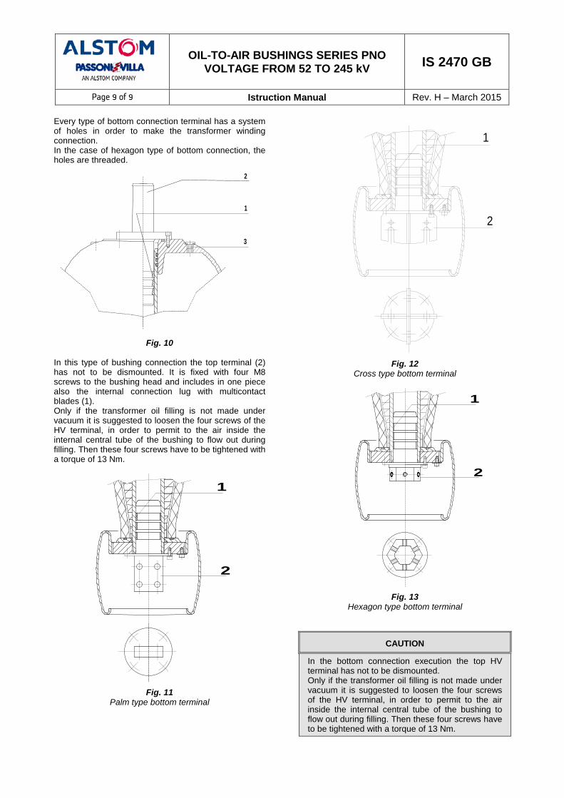
Page 9 of 9 Istruction Manual Rev. H – March 2015 Every type of bottom connection terminal has a system of holes in order to make the transformer winding connection. In the case of hexagon type of bottom connection, the holes are threaded.
2
1
3
Fig. 10
In this type of bushing connection the top terminal (2) has not to be dismounted. It is fixed with four M8 screws to the bushing head and includes in one piece also the internal connection lug with multicontact blades (1). Only if the transformer oil filling is not made under vacuum it is suggested to loosen the four screws of the HV terminal, in order to permit to the air inside the internal central tube of the bushing to flow out during filling. Then these four screws have to be tightened with a torque of 13 Nm.
1
2
Fig. 11
Palm type bottom terminal
1
2
Fig. 12
Cross type bottom terminal
1
2
Fig. 13
Hexagon type bottom terminal
CAUTION
In the bottom connection execution the top HV terminal has not to be dismounted. Only if the transformer oil filling is not made under vacuum it is suggested to loosen the four screws of the HV terminal, in order to permit to the air inside the internal central tube of the bushing to flow out during filling. Then these four screws have to be tightened with a torque of 13 Nm.

OIL-TO-AIR BUSHINGS SERIES PNO VOLTAGE FROM 52 TO 245 kV IS 2470 GB
Page 10 of 9 Istruction Manual Rev. H – March 2015
Fig. 14
Clamping type bottom terminal
4.4 OIL SIDE SHIELD
The bottom end of the bushing is shielded by a suitable aluminium insulated electrode. It has the function of increasing the dielectric strength in oil and screen the connection between the lead coming form the transformer winding and the bushing itself. This deflector is removable to make easier the connection between transformer cable and bushing. There are two shield’s versions: • Deflector removable upwards: it can be unscrewed
upwards (fig. 15). • Deflector with bayonet coupling: it can be removed
downwards rotating and pulling down its body. In the first execution, in a suitable slot on the thread there an o-ring is placed in order to act as a brake against a possible deflector’s movement due to vibrations during service. Take care that this remains in its slot during deflector dismounting.
Fig. 15
CAUTION
During handling, take care to not damage the exter-nal finishing coat of the dielectric shield, important in the dielectric strength of the bushing oil side.
4.5 ICE AND SNOW DEPOSITS
If the transformer is installed in arctic climate with bushings mounted in inclined position, and has to be put in service, it is recommendable before to remove from every bushing’s porcelain excessive ice or snow deposits, which can reduce the dielectric withstand capability. 4.6 OIL FILLING OF THE TUBE OF THE BUSHING
It is foreseen that the bushing operates with the inner tube filled with the transformer’s oil at least up to the flange, in order to improve the bushing cooling.
After the closure of the bushing, it is necessary to make the vacuum on the transformer and then fill it with oil. In case the oil filling is made from the top of the transformer without the vacuum treatment, it is necessary to be sure that the oil level reaches the bushing flange, without the presence of air bubbles. For this purpose, the flange is provided with a plug which allows the air to flow out (fig. 16). Furthermore lift a bit the HV terminal in order to allow the air to go out and complete the filling of the transformer and of the lower part of the inner tube of the bushing.
Bushings can withstand the vacuum conditions and temperature (up to 90°C) which occur during the treatment of the live part made inside the transformer case.
CAUTION
The characteristic of withstanding vacuum and temperature refers to new bushings. In case of old bushings it must be considered the natural de-rating and ageing of the gaskets
4.7 OIL LEVEL REGULATION
In the factory, the bushings are filled with oil in order the oil level reaches about the half of the prismatic indicator at 20°C. Bushings are filled in order to assure, in vertical position, a visible oil level in the whole range of operating temperatures. When the bushing is mounted on the transformer in inclined position with an angle higher than 10-15° from the vertical, it should be better to regulate the oil level. Remove some bushing’s oil or add transformer mineral oil accurately treated, through the head’s plug placed in the upper part of the head, near the HV terminal (item 5 – fig. 9, item 3 – fig. 10) in order to have a visible oil level in the whole range of operating temperatures.
OIL-TO-AIR BUSHINGS SERIES PNO VOLTAGE FROM 52 TO 245 kV IS 2470 GB
Page 11 of 9 Istruction Manual Rev. H – March 2015 4.8 CONNECTION TO BUCHHOLZ RELAY
A 1/2” GAS plug is placed on the bushing flange (fig. 16) in order to:
• Connect the relay tube, if foreseen;
• Eliminate the air pocket which may be formed during some executions and by the filling of the upper part of the transformer not under vacuum.
In this case we suggest to unscrew the plug and leave the air flowing. When the oil begins to come out, close the plug.
1/2" GAS
Fig. 16
5 TEMPERATURE LIMITS
Bushings of the series PNO are designed for operation at temperatures according to IEC 60137 Standard: Ambient temperature: Maximum: + 40°C Max. daily mean: + 30°C Minimum: - 25°C Oil temperature: Maximum: +100°C Max. daily mean: + 90°C The over-temperatures allowed are in accordance to IEC 60137 Standard.
In order to comply with these limits, in bushing with draw lead connection, it is suggested to use one or more leads, having a total section that gives a current density not higher than 2 A/mm2.
For special requirements regarding low ambient temperatures (up to –60°C) special o-rings are foreseen, made of fluor silicon mixtures for low temperatures. The spring closing system is calibrated in order to maintain the bushing hermeticity at these extreme conditions and the oil maintains its proprieties. For any other special or different condition please inform Passoni & Villa and ask the permission to put in service the bushings 6 SERVICE AND MAINTENANCE 6.1 PAINTING
The flange and the head of the bushing are made of aluminium casting, not treated. The customer therefore has to give a paint coating at the moment of installation on the transformer. Furthermore it is suggested, after a period of 10 years for bushings indoor installation and after 5 years for outdoor ones, to give a further paint coating.
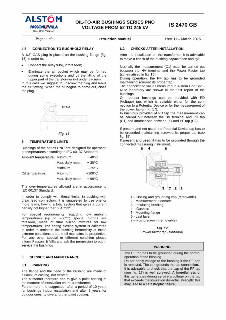
6.2 CHECKS AFTER INSTALLATION
After the installation on the transformer it is advisable to make a check of the bushing capacitance and tgδ. Normally the measurement (C1) must be carried out between the HV terminal and the Power Factor tap (schematised in fig. 16). During operation, the PF tap has to be grounded maintaining screwed its proper tap. The capacitance values measured in Alstom Grid Spa - RPV laboratory are shown in the test report of the bushings. On request bushings can be provided with PD (Voltage) tap, which is suitable either for the con-nection to a Potential Device or for the measurement of the power factor (fig. 17). In bushings provided of PD tap the measurement can be carried out between the HV terminal and PD tap (C1) and another one between PD and PF tap (C2). If present and not used, the Potential Device tap has to be grounded maintaining screwed its proper tap (see fig. 18). If present and used, it has to be grounded through the connected measuring instrument.
6 4 5
3 2 17
1 - Closing and grounding cap (removable) 2 - Measurement electrode 3 - Insulating bushing 4 – Gaskets 5 - Mounting flange 6 - Last layer 7 – Fixing screw (irremovable)
Fig. 17
Power factor tap (standard)
WARNING
The PF tap has to be grounded during the normal operation of the bushing. Do not apply voltage to the bushing if the PF cap is removed. The cap grounds the tap connection. It is advisable to check that the cap of the PF tap (see fig. 17) is well screwed. A forgetfulness of this generates during service a voltage on the tap that exceeds the insulation dielectric strength: this may lead to a catastrophic failure.
OIL-TO-AIR BUSHINGS SERIES PNO VOLTAGE FROM 52 TO 245 kV IS 2470 GB
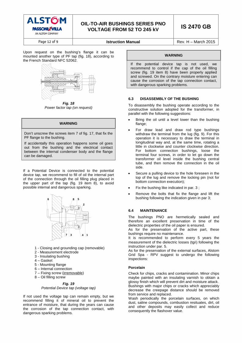
Page 12 of 9 Istruction Manual Rev. H – March 2015 Upon request on the bushing’s flange it can be mounted another type of PF tap (fig. 18), according to the French Standard NFC 52062.
Fig. 18
Power factor tap (on request)
WARNING
Don’t unscrew the screws item 7 of fig. 17, that fix the PF flange to the bushing. If accidentally this operation happens some oil goes out from the bushing and the electrical contact between the internal condenser body and the flange can be damaged.
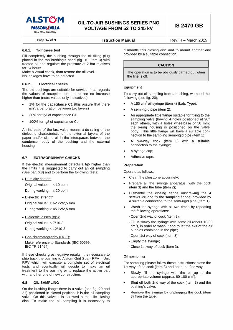
If a Potential Device is connected to the potential device tap, we recommend to fill of oil the internal part of the connection through the oil filling plug placed in the upper part of the tap (fig. 19 item 8), to avoid possible internal and dangerous sparking.
1
2
3 4
56
7
8
1 - Closing and grounding cap (removable) 2 - Measurement electrode 3 - Insulating bushing 4 – Gasket 5 - Mounting flange 6 – Internal connection 7 – Fixing screw (irremovable) 8 – Oil filling screw
Fig. 19 Potential Device tap (voltage tap)
If not used the voltage tap can remain empty, but we recommend filling it of mineral oil to prevent the entrance of moisture, that during the years can cause the corrosion of the tap connection contact, with dangerous sparking problems.
WARNING
If the potential device tap is not used, we recommend to control if the cap of the oil filling screw (fig. 19 item 8) have been properly applied and screwed. On the contrary moisture entering can cause the corrosion of the tap connection contact, with dangerous sparking problems.
6.3 DISASSEMBLY OF THE BUSHING
To disassembly the bushing operate according to the constructive solution adopted for the transformer, in parallel with the following suggestions: • Bring the oil until a level lower than the bushing
flange; • For draw lead and draw rod type bushings
withdraw the terminal from the lug (fig. 9). For this operation it is necessary to draw the terminal in longitudinal way and, at the same time, rotating a little in clockwise and counter clockwise direction. For bottom connection bushings, loose the terminal four screws, in order to let go down the transformer oil level inside the bushing central tube, and then remove the connection in the oil side.
• Secure a pulling device to the hole foreseen in the top of the lug and remove the locking pin (not for bottom connection execution);
• Fix the bushing like indicated in par. 3 ; • Remove the bolts that fix the flange and lift the
bushing following the indication given in par 3; 6.4 MAINTENANCE
The bushings PNO are hermetically sealed and therefore an excellent preservation in time of the dielectric properties of the oil paper is ensured. As for the preservation of the active part, these bushings require no maintenance. It is recommended to perform every 5 years the measurement of the dielectric losses (tgδ) following the instruction under par. 5. As for the preservation of the external surfaces, Alstom Grid Spa - RPV suggest to undergo the following inspections: Porcelain Check for chips, cracks and contamination. Minor chips maybe painted with an insulating varnish to obtain a glossy finish which will prevent dirt and moisture attack. Bushings with major chips or cracks which appreciably decrease the creepage distance should be removed from service and replaced. Wash periodically the porcelain surfaces, on which dust, saline compounds, combustion resituates, dirt, oil and other deposits may easily collect and reduce consequently the flashover value.

OIL-TO-AIR BUSHINGS SERIES PNO VOLTAGE FROM 52 TO 245 kV IS 2470 GB
Page 13 of 9 Istruction Manual Rev. H – March 2015 If the transformer has to be put in service during winter, it is recommendable before to clean the bushing’s porcelain from ice or snow that can reduce the dielectric withstand capability. HV terminals Check the connections in order to avoid poor contacts and consequent overheating. Make particular attention on the air side connections, more subject to oxidation than the oil side ones. In case of connections surfaces very oxidised, clean them slightly passing fine sandpaper, paying attention to not damage the tinned layer, if present. After this operation, clean well the surfaces with a light solvent (for example alcohol). Power factor tap Check the proper location of the tap cap and its suitable complete screwing in order to prevent entrance of moisture (Fig. 17). Potential device tap (Voltage tap) If present and not used, check the proper location and the suitable complete screwing either of the tap cap and the oil filling screw, in order to prevent entrance of moisture (Fig. 19). Voltage tap If not used can remain empty, but we recommend to fill it of mineral oil to prevent the entrance of moisture, that during the years can cause the corrosion of the tap connection contact, with dangerous sparking problems Metal parts It is advisable after a period of 10 years for bushings indoor installation and after 5 years for outdoor ones, to give a further paint coating. Oil level Check the oil level of the bushing and add oil if necessary. The refilling can be done throughout the tap positioned in the upper part of the head, near the HV terminal (item 5 – fig. 9, item 3 - fig. 10), by using the same transformer mineral oil, accurately treated and degassed. Mineral oil is fully compatible with the impregnating DDB synthetic bushing’s oil. Close the cap with a tightening torque of 100 Nm. The refilling of the gas cushion on the top head of the bushing with nitrogen or dry air is not strictly necessary. In case the oil level would go down, check carefully if any external leakage is present. If nothing will be detected then refill the bushing. If the oil level still go down it is necessary to remove the bushing from the service and to repair it. The oil inside the bushing is not toxic and perfectly miscible with mineral transformer oil, both from the physical and chemical point of view and from the dielectric and thermal properties.
CAUTION
To prevent oxidation of the bushing oil and humidity entering, the filling plug has to be closed just after the conclusion of the refilling operation.
6.5 MEASUREMENT OF DIELECTRIC LOSSES
Test in the factory
The Standard - IEC Publication 60137 - states that the oil-paper bushings must have a tanδ less than 7x10⁻³. The measurement is performed in our Test Laboratory by means of a Schering bridge (Tettex type) at the voltages requested by the Standards. All values are shown in the Test Report. Measurement at the voltage of 10 kV is carried out in order to have a reference value for comparison with measurements made at site during the service of the bushing. Test on the bushing installed on the transformer
With the bushing already installed on the transformer and the HV terminal disconnected, the measurement can be performed by means of a bridge, by applying a voltage of 10 kV between the HV terminal and PF tap (or PD if present), maintaining grounded the flange (C1 measurement). The bushing is considered good if a tgδ less than the maximum one established by the Standards is measured. If a tgδ higher than the above one is measured, please contact Alstom Grid Spa RPV that will decide if it is necessary to make other tests before removing the bushing from service or to ship it back, in order to make a complete check and eventually to carry out an oil treatment or eventually to replace the active part with another of new manufacture. In order to measure the Co value (capacitance between the PF tap and flange) the flange has to be supplied with a voltage maximum of 2 kV and the PF tap has to be connected to the bridge. In case of presence of PD tap, this one can be supplied with a max voltage of 10 kV and the PF tap has to be connected to the bridge (C2 measurement).
A field measurement of tgδ and capacitance can differ from the measurements carried out in the factory due to the different conditions of test and relevant accuracy: for this reason a light shifting (max 10% for tgδ) is acceptable. Furthermore the installation conditions, due to stray capacitances, can affect the capacitance value. For this it is advisable to measure capacitance and tgδ upon the installation and use these values as base for future comparison measurements. 6.6 CHECKS ON OLD BUSHINGS
Before remounting an old bushing it is advisable to carry out a tightness test and an electrical check.
OIL-TO-AIR BUSHINGS SERIES PNO VOLTAGE FROM 52 TO 245 kV IS 2470 GB
Page 14 of 9 Istruction Manual Rev. H – March 2015 6.6.1. Tightness test Fill completely the bushing through the oil filling plug placed in the top bushing’s head (fig. 10, item 3) with treated oil and regulate the pressure at 2 bar relatives for 24 hours. Make a visual check, than restore the oil level. No leakages have to be detected. 6.6.2. Electrical checks The old bushings are suitable for service if, as regards the values of reception test, there are no increase higher than (note: values only indicatives):
• 1% for the capacitance C1 (this assure that there isn’t a perforation between two layers)
• 30% for tgδ of capacitance C1.
• 100% for tgδ of capacitance Co. An increase of the last value means a de-rating of the dielectric characteristic of the external layers of the paper and/or of the oil in the interspaces between the condenser body of the bushing and the external housing. 6.7 EXTRAORDINARY CHECKS
If the electric measurement detects a tgδ higher than the limits it is suggested to carry out an oil sampling (See par. 6.8) and to perform the following tests:
• Humidity content Original value: ≤ 10 ppm During working: ≤ 20 ppm
• Dielectric strength Original value: ≥ 62 kV/2,5 mm During working: ≥ 45 kV/2,5 mm
• Dielectric losses (tgδ): Original value: ≤ 7*10-3 During working: ≤ 12*10-3
• Gas chromatography (DGE): Make reference to Standards (IEC 60599, IEC TR 61464)
If these checks give negative results, it is necessary to ship back the bushing to Alstom Grid Spa - RPV – Unit RPV which will execute a complete set of electrical tests and eventually will decide to make an oil treatment to the bushing or to replace the active part with another one of new construction. 6.8 OIL SAMPLING
On the bushing flange there is a valve (see fig. 20 and 21) positioned in closed position: it is the oil sampling valve. On this valve it is screwed a metallic closing disc. To make the oil sampling it is necessary to
dismantle this closing disc and to mount another one provided by a suitable connection.
CAUTION
The operation is to be obviously carried out when the line is off.
Equipment
To carry out oil sampling from a bushing, we need the following (see fig. 20): • A 150 cm3 oil syringe (item 4) (Lab. Type); • A semi-rigid pipe (item 2); • An appropriate little flange suitable for fixing to the
sampling valve (having 4 holes positioned at 90° each others, with a holes wheelbase of 50 mm; the o-ring housing is positioned on the valve body). This little flange will have a suitable con-nection to the sampling semi-rigid pipe (item 1);
• A two-way cock (item 3) with a suitable connection to the syringe;
• A syringe cap; • Adhesive tape. Preparation
Operate as follows: • Clean the plug zone accurately; • Prepare all the syringe apparatus, with the cock
(item 3) and the tube (item 2); • Dismantle the closing flange unscrewing the 4
screws M8 and fix the sampling flange, provided by a suitable connection to the semi-rigid pipe (item 1);
• Wash the syringe with oil two times by repeating the following operations:
- Open 2nd way of cock (item 3); - Fill in slowly the syringe with some oil (about 10-30 cm3), in order to wash it and to let the exit of the air bubbles contained in the pipe;
- Open 1st way of cock (item 3); - Empty the syringe; - Close 1st way of cock (item 3).
Oil sampling
For sampling please follow these instructions: close the 1st way of the cock (item 3) and open the 2nd way; • Slowly fill the syringe with the oil up to the
appropriate volume (approx. 60-100 cm3); • Shut off both 2nd way of the cock (item 3) and the
bushing’s valve; • Remove the syringe by unplugging the cock (item
3) from the tube;

OIL-TO-AIR BUSHINGS SERIES PNO VOLTAGE FROM 52 TO 245 kV IS 2470 GB
Page 15 of 9 Istruction Manual Rev. H – March 2015
WARNING
To ease the oil exit and to remove the low depression that can be generated inside the bushing in case of low temperature, phenomenon that can allow a dangerous air incoming in the bushing from the sampling valve, it is suggested to loosen the filling tap located on the top bushing’s head.
Fig. 20
°70 °90
Fig. 21
• Set the syringe with the cock (item 3) being up; • Unplug the cock (item 3) and place a closing cap on
the syringe; • Clean the syringe and block it with adhesive tape on
which you will write down the bushing part number; • Overturn the syringe and keep it with its cap down;
• Remove the pipe from the plug, unscrew the sampling flange and screw the original one;
• Screw completely the filling tap on the head of the bushing (item 3, fig. 10).
The above mentioned operations involve on the whole a sampling of about 0.2-0.3 litres of bushing oil. The oil taken out has to be restored by adding the same quantity of transformer mineral oil, accurately treated and degassed, which is perfectly miscible with the synthetic bushing oil. The refilling must be done through the tap located on the top of the bushing’s head (item 3, fig. 10), which must be closed immediately after the end of the operations.
CAUTION
The oil sampling operation has to be carried out as quickly as possible and in a period with a low humidity level, in order to not pollute the oil
7 DISPOSAL AT THE END OF LIFETIME
The bushing consists of the following material: Component Material Winding conductor Copper or aluminium alloy
Terminals and bottom plates
Copper, aluminium alloy or brass; optional silver or tin coating
Insulating oil Mineral oil acc. IEC60296
Winding Cellulose paper and thin aluminium foils
Nuts, bolts, washers and springs Stainless steel, carbon steel
Top oil expansion vessel Aluminium alloy
Flange and extension Aluminium alloy
PF tap and cover Nickel or tin coated brass, tin coated copper
Top insulator
Either porcelain acc. To IEC60672 or composite insulator made of:
Glass fibre reinforced epoxy Silicone
Insulator fittings Aluminium alloy
Bottom insulator Either porcelain acc. IEC60672 or epoxy resin
Bottom shield Aluminium alloy covered with either epoxy paint or epoxy resin
1
4
3
2
Bushing
First
Second