Embed Size (px)
Citation preview
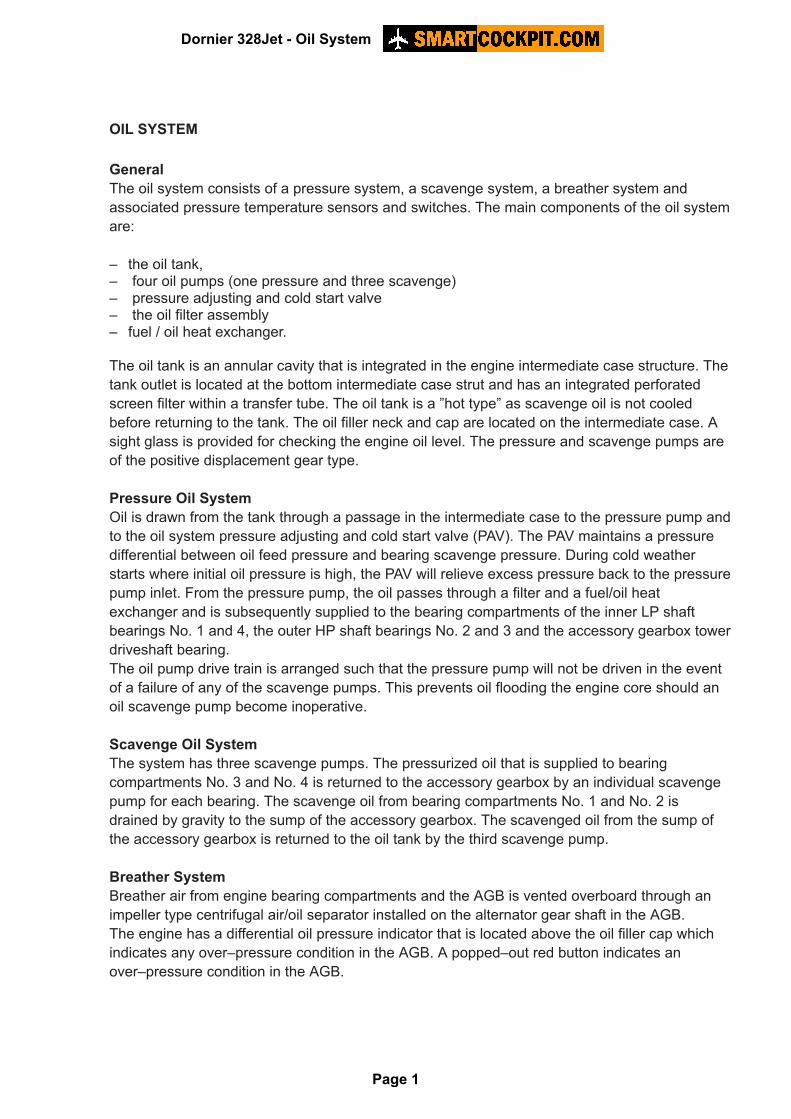
OIL SYSTEM
GeneralThe oil system consists of a pressure system, a scavenge system, a breather system andassociated pressure temperature sensors and switches. The main components of the oil systemare:
– the oil tank,– four oil pumps (one pressure and three scavenge)– pressure adjusting and cold start valve– the oil filter assembly– fuel / oil heat exchanger.
The oil tank is an annular cavity that is integrated in the engine intermediate case structure. Thetank outlet is located at the bottom intermediate case strut and has an integrated perforatedscreen filter within a transfer tube. The oil tank is a ”hot type” as scavenge oil is not cooledbefore returning to the tank. The oil filler neck and cap are located on the intermediate case. Asight glass is provided for checking the engine oil level. The pressure and scavenge pumps areof the positive displacement gear type.
Pressure Oil SystemOil is drawn from the tank through a passage in the intermediate case to the pressure pump andto the oil system pressure adjusting and cold start valve (PAV). The PAV maintains a pressuredifferential between oil feed pressure and bearing scavenge pressure. During cold weatherstarts where initial oil pressure is high, the PAV will relieve excess pressure back to the pressurepump inlet. From the pressure pump, the oil passes through a filter and a fuel/oil heatexchanger and is subsequently supplied to the bearing compartments of the inner LP shaftbearings No. 1 and 4, the outer HP shaft bearings No. 2 and 3 and the accessory gearbox towerdriveshaft bearing.The oil pump drive train is arranged such that the pressure pump will not be driven in the eventof a failure of any of the scavenge pumps. This prevents oil flooding the engine core should anoil scavenge pump become inoperative.
Scavenge Oil SystemThe system has three scavenge pumps. The pressurized oil that is supplied to bearingcompartments No. 3 and No. 4 is returned to the accessory gearbox by an individual scavengepump for each bearing. The scavenge oil from bearing compartments No. 1 and No. 2 isdrained by gravity to the sump of the accessory gearbox. The scavenged oil from the sump ofthe accessory gearbox is returned to the oil tank by the third scavenge pump.
Breather SystemBreather air from engine bearing compartments and the AGB is vented overboard through animpeller type centrifugal air/oil separator installed on the alternator gear shaft in the AGB. The engine has a differential oil pressure indicator that is located above the oil filler cap whichindicates any over–pressure condition in the AGB. A popped–out red button indicates anover–pressure condition in the AGB.
Dornier 328Jet - Oil System
Page 1
Pressure and Sensors and Switches and Temperature SensorSensors and switches on the engine monitor the oil pressure and oil temperature and providethe information for indications on the EICAS. The following sensors and switches are fitted toeach engine:
– pressure sensor (EICAS bar are digital readout)– oil filter differential pressure switch (warns of oil filter blockage)– low pressure switch (oil prerssure warning on Reed Warning Panel)– temperature sensor (EICAS bar and digital readout).
Dornier 328Jet - Oil System
Page 2
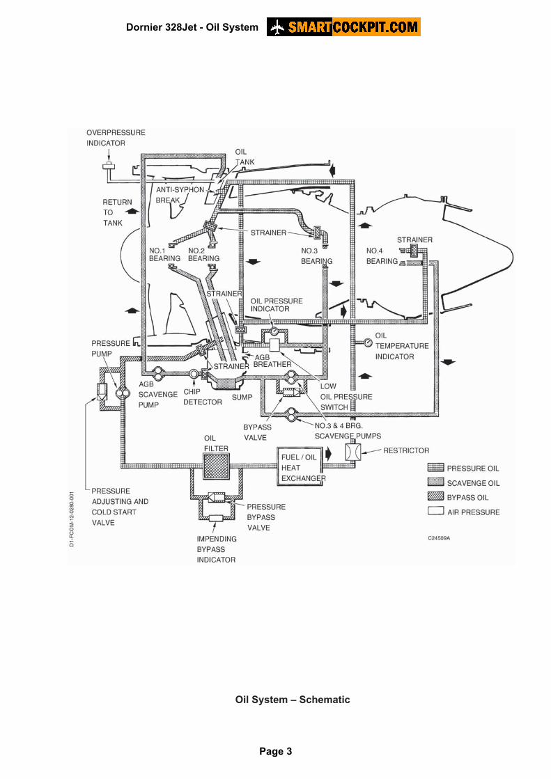
Oil System – Schematic
Dornier 328Jet - Oil System
Page 3
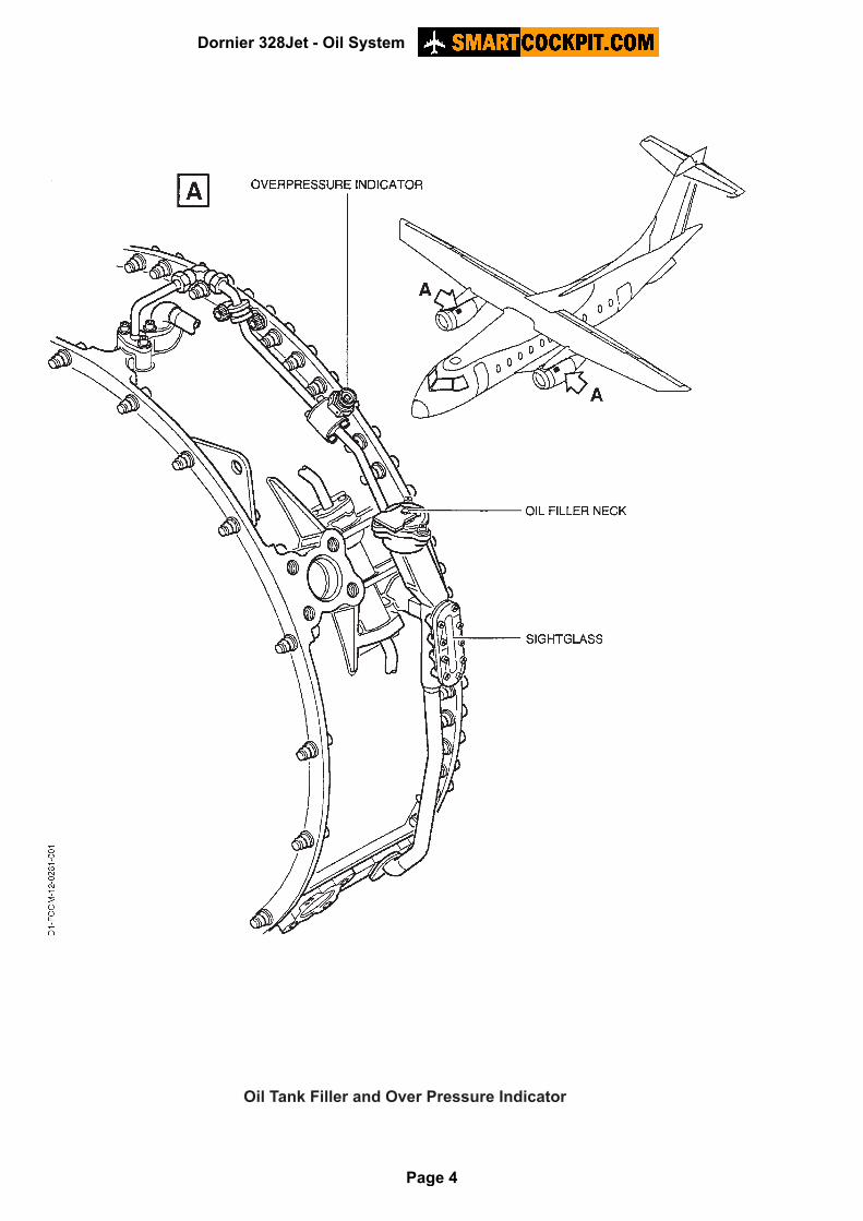
Oil Tank Filler and Over Pressure Indicator
Dornier 328Jet - Oil System
Page 4
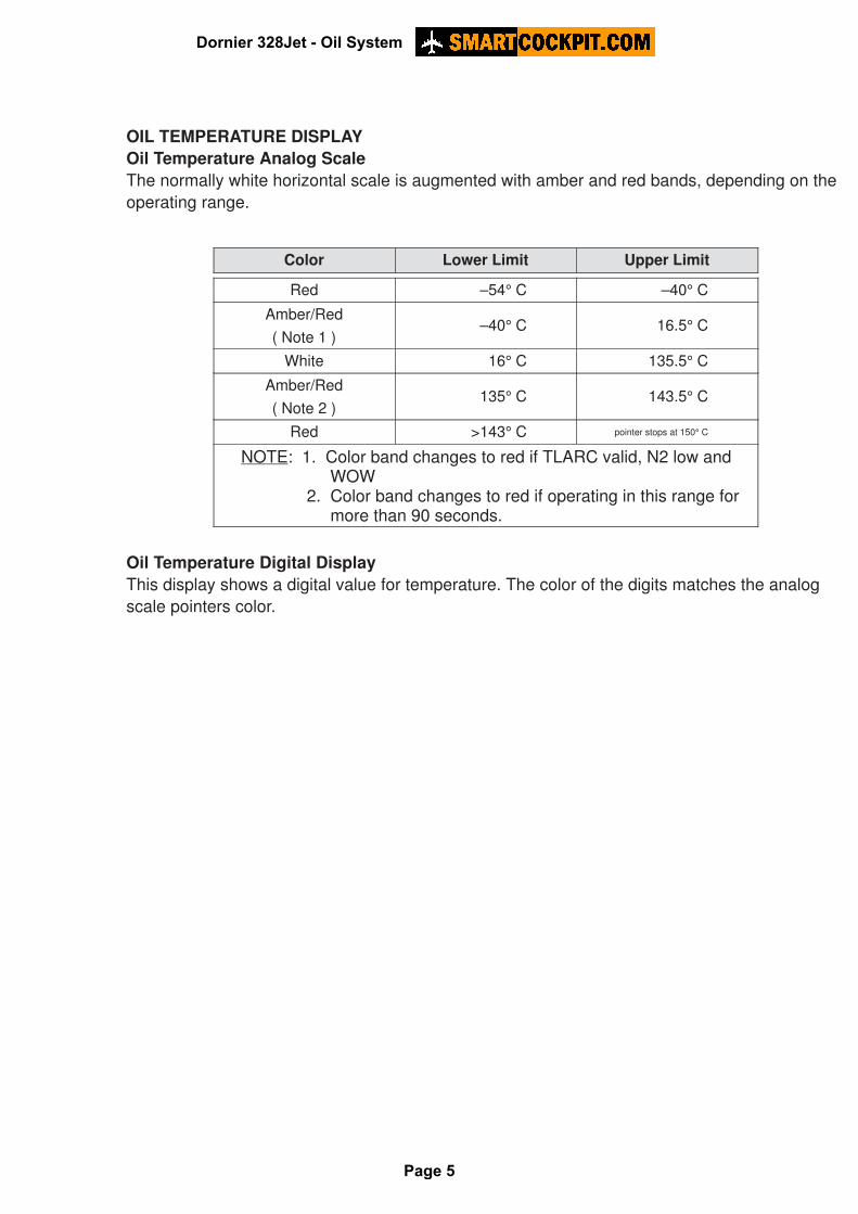
OIL TEMPERATURE DISPLAYOil Temperature Analog ScaleThe normally white horizontal scale is augmented with amber and red bands, depending on theoperating range.
Color Lower Limit Upper Limit
Red –54° C –40° CAmber/Red
( Note 1 )–40° C 16.5° C
White 16° C 135.5° CAmber/Red
( Note 2 )135° C 143.5° C
Red >143° C pointer stops at 150° C
NOTE: 1. Color band changes to red if TLARC valid, N2 low and WOW 2. Color band changes to red if operating in this range for more than 90 seconds.
Oil Temperature Digital DisplayThis display shows a digital value for temperature. The color of the digits matches the analogscale pointers color.
Dornier 328Jet - Oil System
Page 5
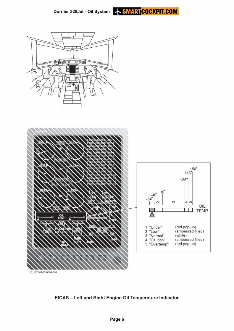
EICAS – Left and Right Engine Oil Temperature Indicator
Dornier 328Jet - Oil System
Page 6
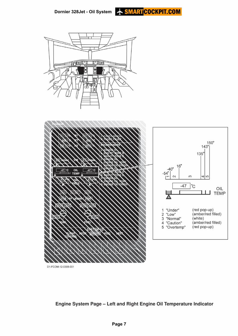
Engine System Page – Left and Right Engine Oil Temperature Indicator
Dornier 328Jet - Oil System
Page 7
OIL PRESSURE DISPLAYOil Pressure Analog ScaleThe normally white horizontal scale is augmented with amber and red bands, depending on theoperating range.
Lower Limit Upper Limit Pointer Color Band Color
0 PSI 10.5 PSI Amber/Red( Note 1 )
Amber/Red( Note 1 )
10 PSI 20.5 PSI Amber/Red( Note 2 )
Amber/Red( Note 2 )
20 PSI 36 PSI White/Amber(Note 3)
White/Amber(Note 3)
35.5 PSI 110.5 PSI White None
110.5 PSI 220.5 PSI Amber/Red( Note 4 )
Amber/Red( Note 4 )
220 PSI Red Red
NOTE: 1. Color band changes to Red if 0 PSI � POIL � 10.5 PSI after 25 sec.2. Color band changes to Red if 10 PSI � POIL � 20.5 PSI after 90 sec.3. White at N2 < 80% and amber at N2 � 80%.4. Color band changes to Red if 110 PSI � POIL � 220.5 PSI after 90 sec. and TOIL > 16° C.
Oil Pressure Digital DisplayThis display shows a digital value for pressure. The color of the digits matches the analog scalepointers color.
Dornier 328Jet - Oil System
Page 8
EICAS – Left and Right Engine Oil Pressure Indicator
Dornier 328Jet - Oil System
Page 9
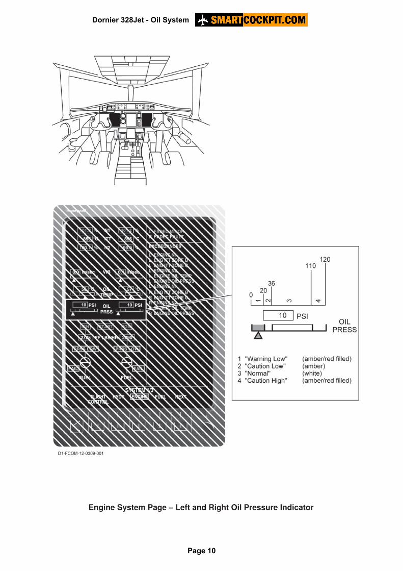
Engine System Page – Left and Right Oil Pressure Indicator
Dornier 328Jet - Oil System
Page 10