Embed Size (px)
Citation preview

Oil Analysis

Increase your understanding of Oil Analysis.
Oil analysis is a Proactive maintenance tool that can Trend Critical Assets Conditions .
We can provide a Fast Turnaround time on urgent samples.

Introduction
What is Oil Analysis?
The Laboratory
The Report
How to Take a Sample
Case Study

Introduction
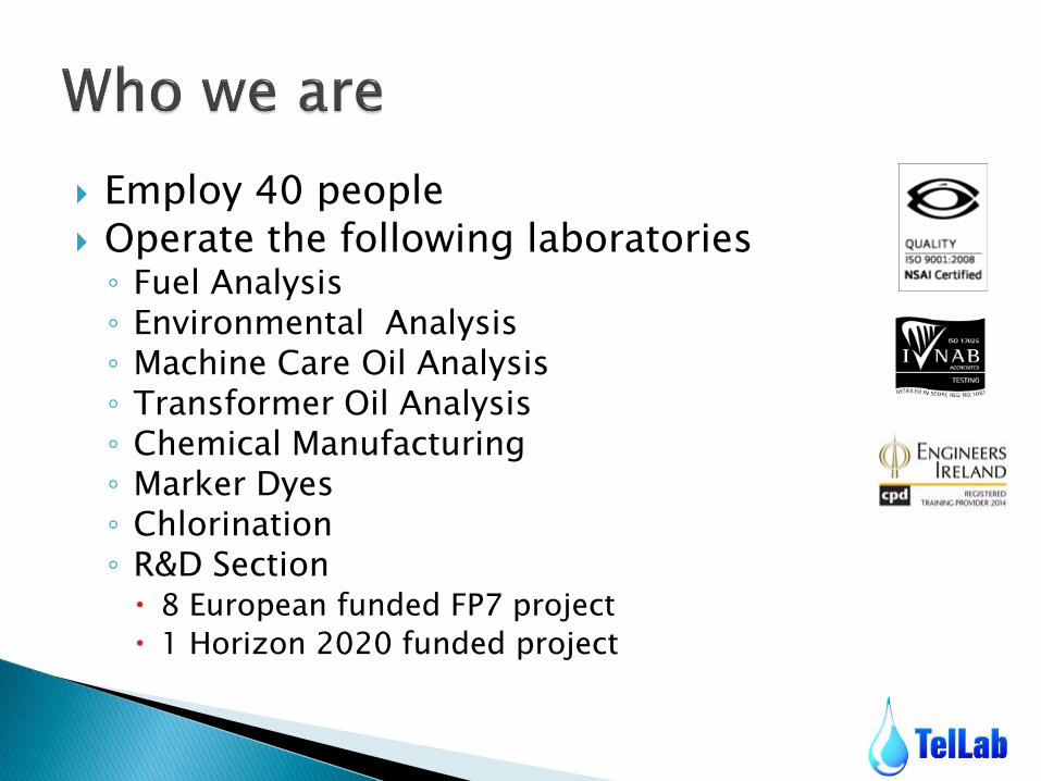
Employ 40 people Operate the following laboratories ◦ Fuel Analysis ◦ Environmental Analysis ◦ Machine Care Oil Analysis ◦ Transformer Oil Analysis ◦ Chemical Manufacturing ◦ Marker Dyes ◦ Chlorination ◦ R&D Section 8 European funded FP7 project
1 Horizon 2020 funded project

Transport ◦ Road
◦ Rail
◦ Shipping
◦ Air
Breweries
Mining
Construction
Power Generation
Injection Moulding
Engines
Transmission
Gearboxes
Turbines ◦ Wind
◦ Gas
◦ Stream
◦ Hydro


What are the benefits?
- Reduced downtime 50-80%*
- Reduced maintenance costs 50-80%*
- Increased machine life 20-40%*
- Productivity increased 20-30%*
- Profit increased 25-60%*
Extended Warranties
* March, Patrick A., ‘Multi-industry survey using predictive maintenance techniques’, 1988.

We test approx 300 samples per week
We have an expertise in mechanical maintenance and lubrication has been built up across various industries in manufacturing & maintenance
Extensive training has been undertaken by our engineers and laboratory technicians
Training Courses offered – International Qualification
What is Oil Analysis?

Functions of a lubricant
- Creates a boundary layer reducing friction
- Dissipates heat from surfaces
- Transports contaminants to filters
- Protects from oxidisation & corrosion
- Power transmission

Tribology – the science of interacting surfaces in relative motion.

Surface finishes are in fact rough on a microscopic scale - Series of troughs (asperities) and peaks The lubricating fluid boundary layer will ideally separate the asperities thus reducing wear
Minimum film thickness Shear mixed layer ~ 1um
thick for steel

Regimes of Lubrication
Hydrodynamic Lubrication
Mixed Lubrication
Boundary Lubrication
High Speed Low Speed Very Low Speed
LOW LOAD HIGH LOAD VERY HIGH LOAD
•Laminar Flow •Film thickness several times greater than surface roughness
•Laminar Flow of oil disturbed •Film thickness same order as Surface roughness
•Boundary Films •Viscous oil properties ineffective

Wear Particle Size in µm (micrometers))
Wea
r P
art
icle
Co
nce
ntr
ati
on
(W
PC
)
0.1 1 10 100 1,000
Catastrophic Failure
Advanced Failure Mode
Onset of Severe Wear Mode
Benign Wear

The Laboratory
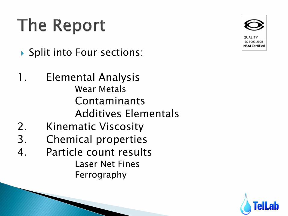
Split into Four sections:
1. Elemental Analysis Wear Metals
Contaminants Additives Elementals
2. Kinematic Viscosity 3. Chemical properties 4. Particle count results
Laser Net Fines Ferrography

Analyses 21 parameters simultaneously
30 second run time
Measures metals, additive levels, contaminants and silica/dirt within the oil sample

Metal Gears Hydraulics
Iron (Fe) Gears, Bearings, Shaft, Housing
Rods, Cylinders, Gears
Chromium (Cr) Roller Bearings Shaft
Aluminum (Al) Pumps, Thrust Washers
Bearings, Thrust Plates
Nickel (Ni) Steel Alloy from Roller Bearings and Shaft
Copper (Cu) Bushings, Thrust Plates
Bushings, Thrust Plates, Lube Coolers
Lead (Pb) Bushings (Bronze Alloy), Grease Contamination
Bushings (Bronze Alloy)
Tin (Sn) Bearing Cage Metal, Lube Additive
Molybdenum (Mo) Ring Plating, Lube Additive, Coolant Inhibitor
Lube Additive, Coolant Inhibitor
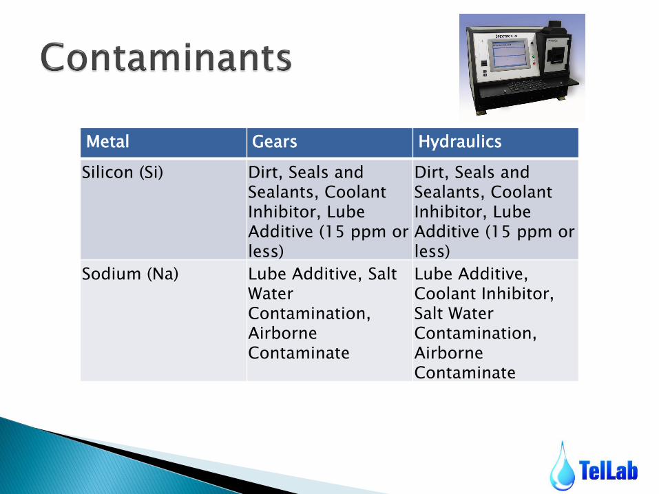
Metal Gears Hydraulics
Silicon (Si) Dirt, Seals and Sealants, Coolant Inhibitor, Lube Additive (15 ppm or less)
Dirt, Seals and Sealants, Coolant Inhibitor, Lube Additive (15 ppm or less)
Sodium (Na) Lube Additive, Salt Water Contamination, Airborne Contaminate
Lube Additive, Coolant Inhibitor, Salt Water Contamination, Airborne Contaminate
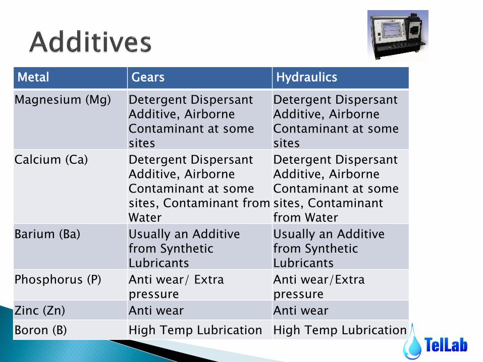
Metal Gears Hydraulics
Magnesium (Mg) Detergent Dispersant Additive, Airborne Contaminant at some sites
Detergent Dispersant Additive, Airborne Contaminant at some sites
Calcium (Ca) Detergent Dispersant Additive, Airborne Contaminant at some sites, Contaminant from Water
Detergent Dispersant Additive, Airborne Contaminant at some sites, Contaminant from Water
Barium (Ba) Usually an Additive from Synthetic Lubricants
Usually an Additive from Synthetic Lubricants
Phosphorus (P) Anti wear/ Extra pressure
Anti wear/Extra pressure
Zinc (Zn) Anti wear Anti wear
Boron (B) High Temp Lubrication High Temp Lubrication
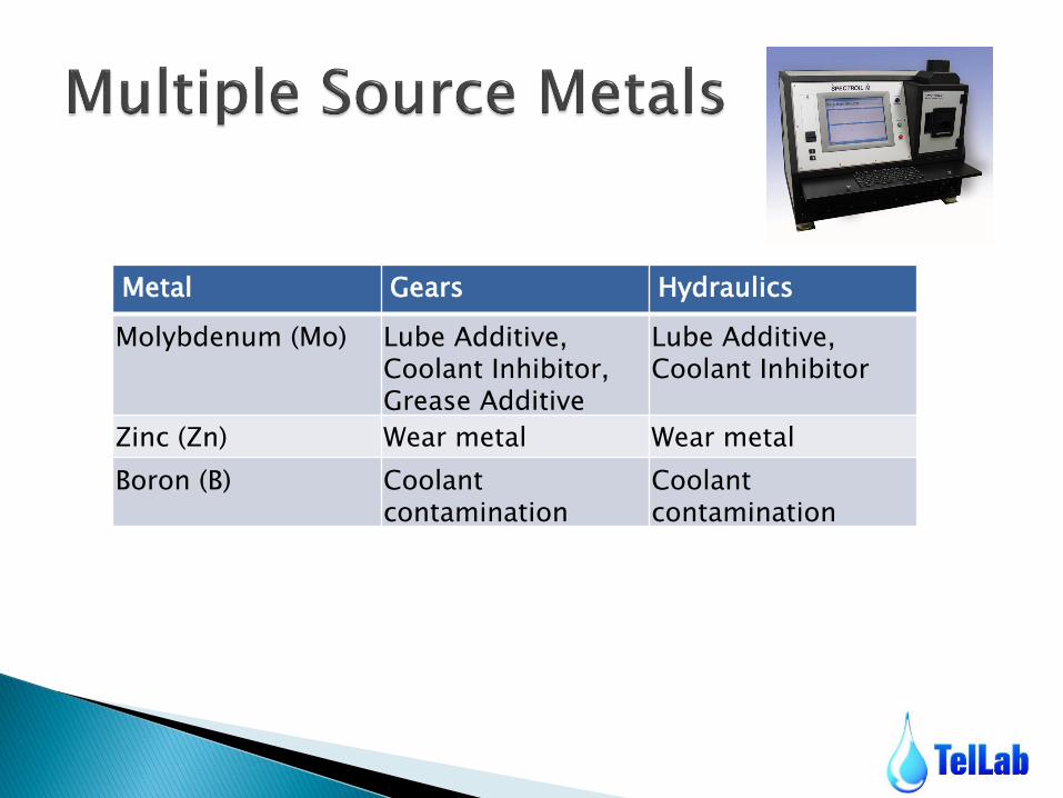
Metal Gears Hydraulics
Molybdenum (Mo) Lube Additive, Coolant Inhibitor, Grease Additive
Lube Additive, Coolant Inhibitor
Zinc (Zn) Wear metal Wear metal
Boron (B) Coolant contamination
Coolant contamination

4 tube automated viscometer (40 -100°C)
All samples measured at 40°C
Samples can be measured above 40°C depending on machine operating temperature
Measures kinematic viscosity in cSt
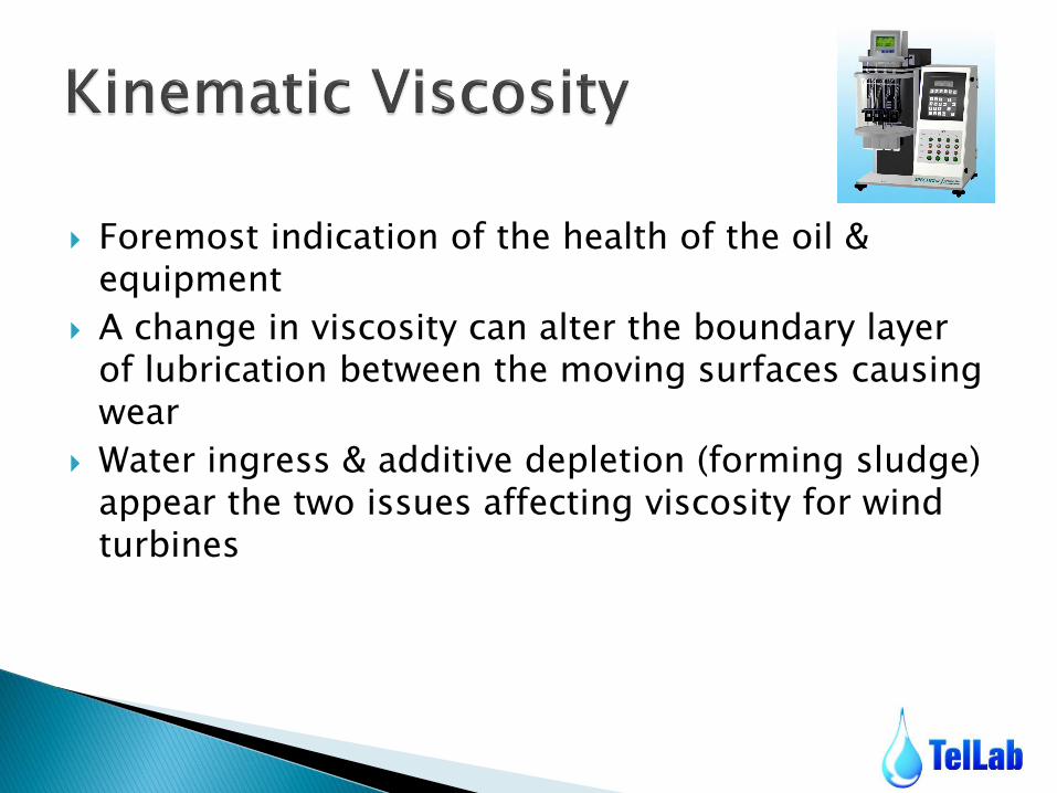
Foremost indication of the health of the oil & equipment
A change in viscosity can alter the boundary layer of lubrication between the moving surfaces causing wear
Water ingress & additive depletion (forming sludge) appear the two issues affecting viscosity for wind turbines

High Viscosity ◦ Increased op costs
◦ Engine overheating
◦ Restricted oil flow
◦ Accelerated wear
◦ Oil- filter by-passed
◦ Harmful deposits/sludge
Low Viscosity ◦ Engine overheating
◦ Poor lubrication
◦ Metal to Metal contact
◦ Increased operating costs
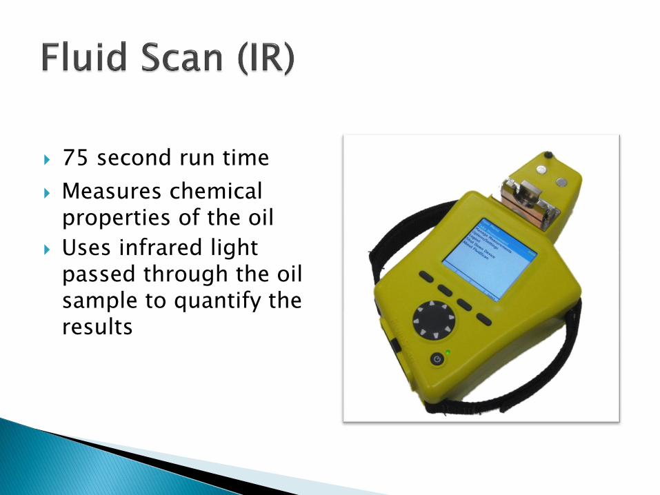
75 second run time
Measures chemical properties of the oil
Uses infrared light passed through the oil sample to quantify the results
FTIR Fluid Scan ◦ TAN (Total Acid Number) – Acid Content
Gearboxes
Hydraulic System
Increases over time.
◦ TBN ( Total Base Number) – Alkaline Additives
Engines . Decreases over time. ( Indicates oil change interval)
◦ Glycol
◦ Fuel Dilution
◦ Soot
◦ Water content
◦ Oxidation , Nitration levels
Virgin oil samples give the maintenance technician invaluable information
- Baseline additive values
- Cleanliness code
- Baseline chemical properties, water & TAN
It is imperative to obtain adequately clean virgin oils and monitor with reference to that cleanliness thereafter

Measures particles from 1-100µm using laser & camera technology
Gives total particle count for that sample & ISO 4406/99 code
Classifies particles in different wear modes
- Cutting, sliding, fatigue,
non-metallic, fibers
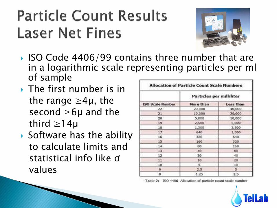
ISO Code 4406/99 contains three number that are in a logarithmic scale representing particles per ml of sample
The first number is in
the range ≥4µ, the
second ≥6µ and the
third ≥14µ
Software has the ability
to calculate limits and
statistical info like ơ
values

Ferrography (Root Cause Analysis)
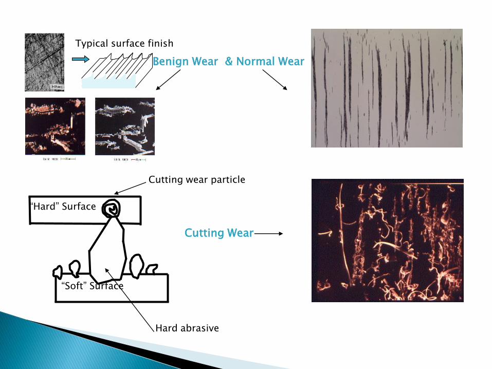
Typical surface finish
“Soft” Surface
“Hard” Surface
Hard abrasive
Cutting wear particle
Benign Wear & Normal Wear
Cutting Wear
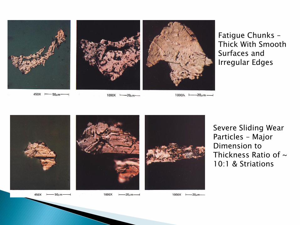
Severe Sliding Wear Particles – Major Dimension to Thickness Ratio of ~ 10:1 & Striations
Fatigue Chunks – Thick With Smooth Surfaces and Irregular Edges

The Report
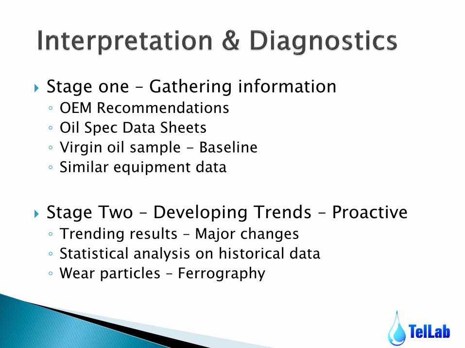
Stage one – Gathering information ◦ OEM Recommendations
◦ Oil Spec Data Sheets
◦ Virgin oil sample - Baseline
◦ Similar equipment data
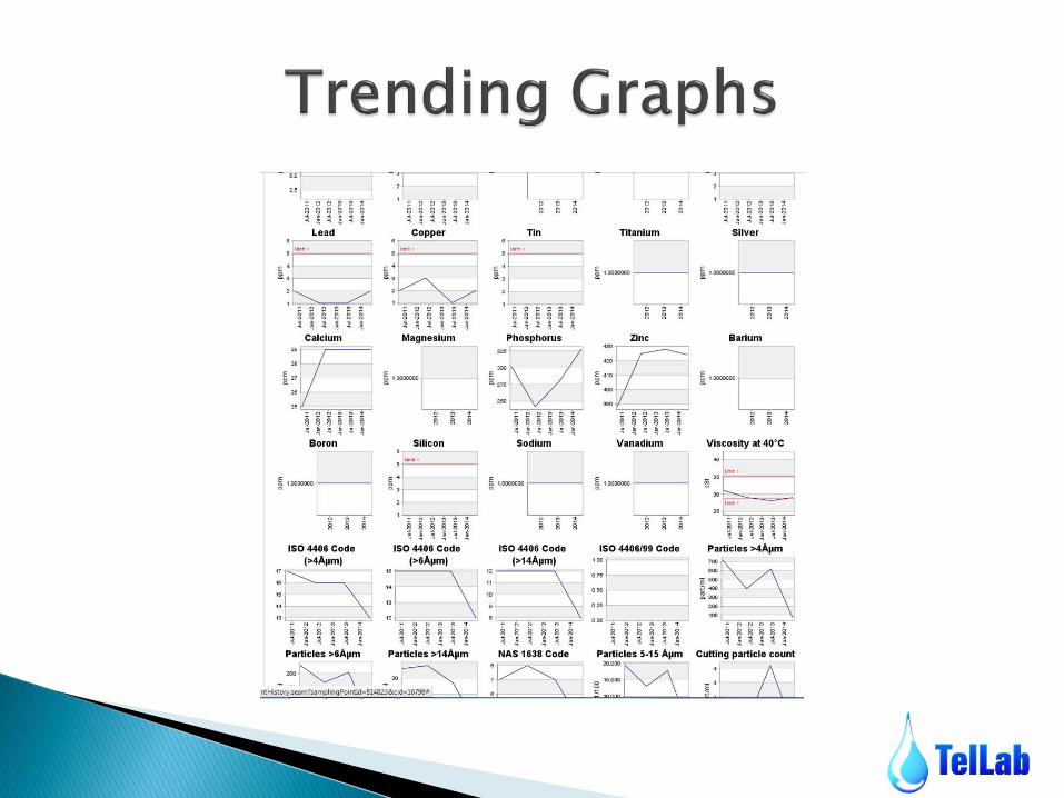
Stage Two – Developing Trends – Proactive ◦ Trending results – Major changes
◦ Statistical analysis on historical data
◦ Wear particles – Ferrography
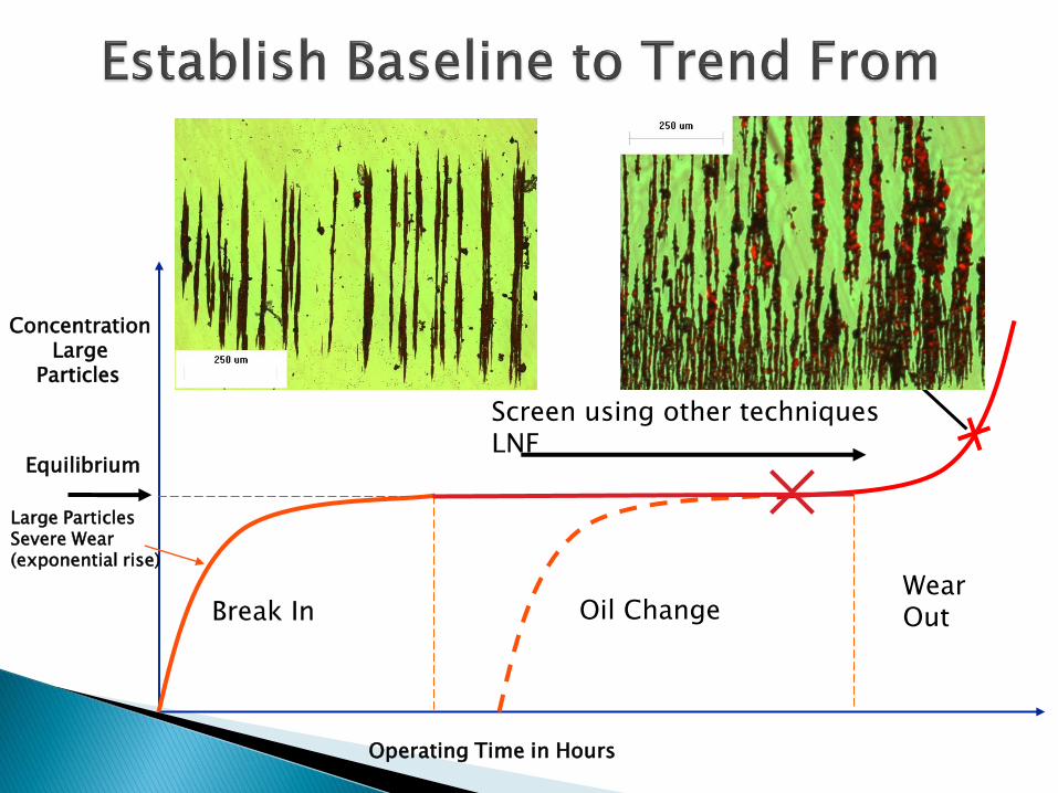
Large Particles Severe Wear (exponential rise)
Operating Time in Hours
Concentration Large
Particles
Oil Change Break In
Equilibrium
Wear Out
Screen using other techniques LNF


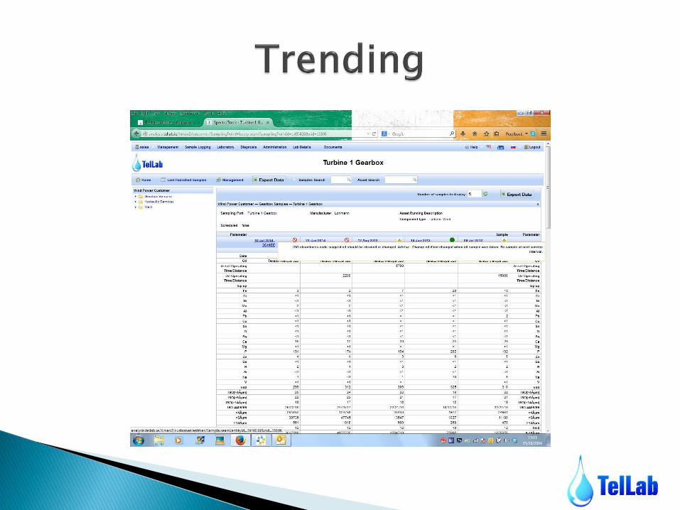


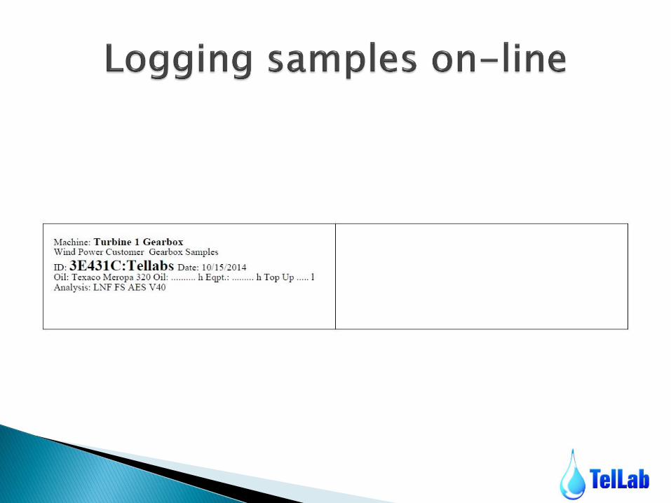
Customers can log samples onto the Spectrotrack database from the customer side and trace the progress from that point
Self logged samples will be given priority upon arriving at the laboratory ahead of any possible back log during busy periods
This will give faster turn around times for the samples

How to Take a Sample
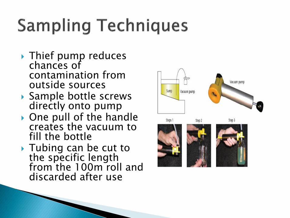
Thief pump reduces chances of contamination from outside sources
Sample bottle screws directly onto pump
One pull of the handle creates the vacuum to fill the bottle
Tubing can be cut to the specific length from the 100m roll and discarded after use

Take sample within 15 minutes of shutdown. Sample must be taken before the filter in the
system. Sampling should be treated with extreme
diligence & care to prevent contamination. Cut tubing to desired length. Pull handle to create vacuum and the bottle will
fill. Once filled unscrew from pump and screw on lid,
making sure sample is not contaminated from the environment.
Wipe bottle, attach label and send to the laboratory.
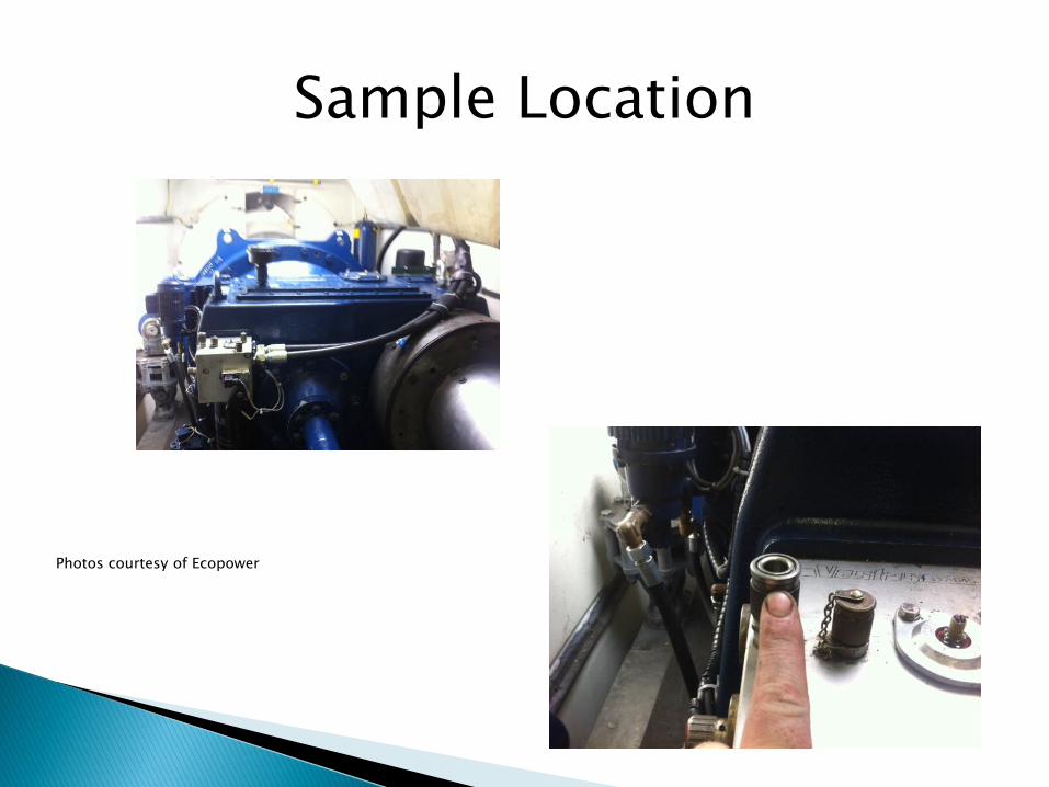
Sample Location
Photos courtesy of Ecopower

Fixed Position sample points

Normal Use Intermittent Use
Diesel Engine Monthly,500 Hours Quarterly
Gas Turbine Monthly,500 Hours Quarterly
Steam Turbine Bi-monthly Quarterly
Gas & Air Comp Monthly,500 Hours Quarterly
Refrigeration Comp Beginning, Midpoint & End of Season
Gears, Bearings Bi-monthly Quarterly
Hydraulic Bi-monthly Quarterly

Case Study - Ferrography

Report ◦ Large Sliding Wear
◦ Severe Copper & White Metal Particles
◦ Moderate Amount of dark-metal oxides
◦ Red oxides present
◦ Silica
◦ Fatigue chunks
Context ◦ 2600 Fleet
◦ Locomotive Engine
◦ Cork Depot
◦ Initial report showed signs of abnormal wear
◦ Engineer concern
Findings Water Ingress Lubricant Starvation
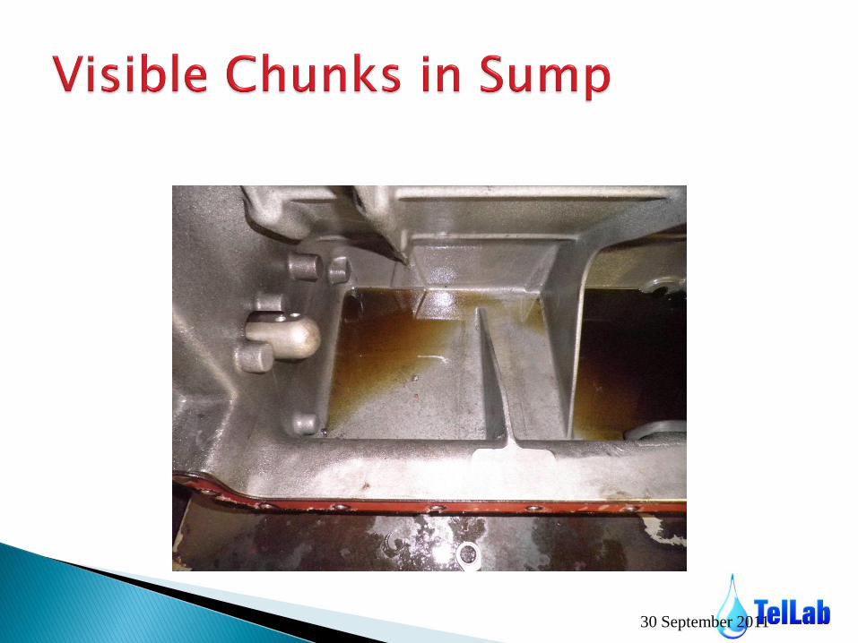
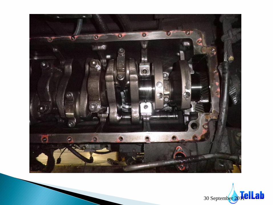
Result Engine Teardown
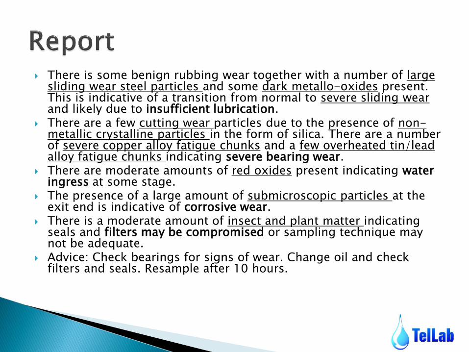
There is some benign rubbing wear together with a number of large sliding wear steel particles and some dark metallo-oxides present. This is indicative of a transition from normal to severe sliding wear and likely due to insufficient lubrication.
There are a few cutting wear particles due to the presence of non-metallic crystalline particles in the form of silica. There are a number of severe copper alloy fatigue chunks and a few overheated tin/lead alloy fatigue chunks indicating severe bearing wear.
There are moderate amounts of red oxides present indicating water ingress at some stage.
The presence of a large amount of submicroscopic particles at the exit end is indicative of corrosive wear.
There is a moderate amount of insect and plant matter indicating seals and filters may be compromised or sampling technique may not be adequate.
Advice: Check bearings for signs of wear. Change oil and check filters and seals. Resample after 10 hours.

30 September 2011

30 September 2011
Entry view (step 1/2 x100
Moderate to heavy amount
of severe wear particles,
with copper and white metal
particles.
Step 3 x500
Moderate amount of Dark-
metallo-oxides indicative of
lubricant starvation and
abnormal wear & red oxides
indicating water ingress.
30 September 2011
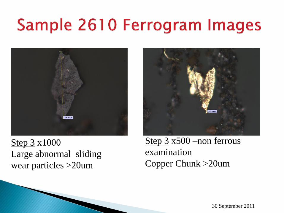
Step 3 x1000
Large abnormal sliding
wear particles >20um
Step 3 x500 –non ferrous
examination
Copper Chunk >20um
30 September 2011
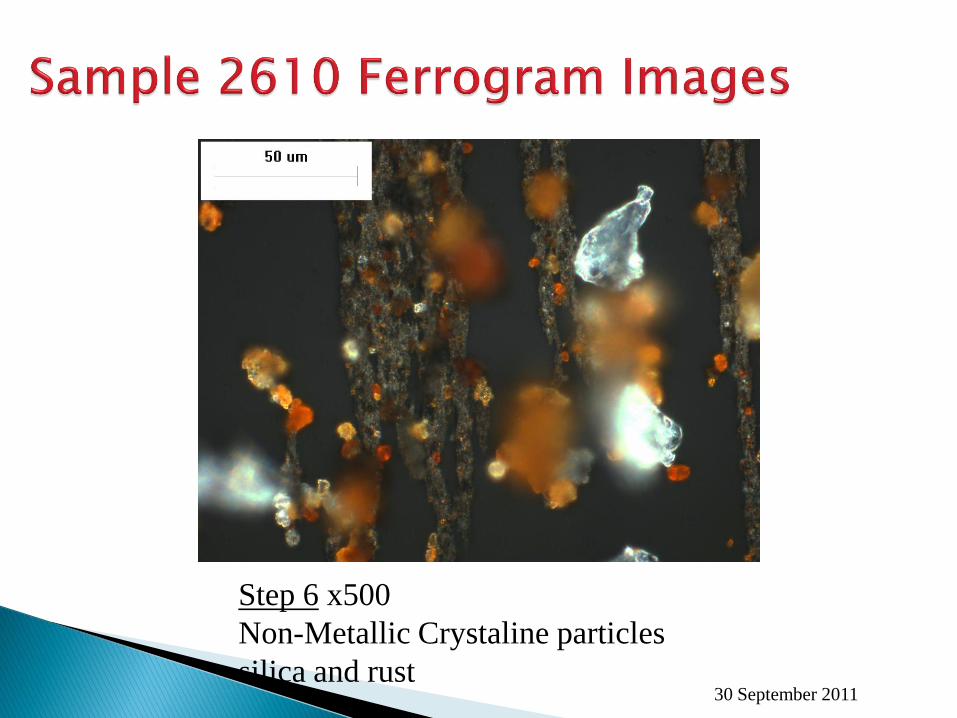
Step 6 x500
Non-Metallic Crystaline particles
silica and rust
30 September 2011
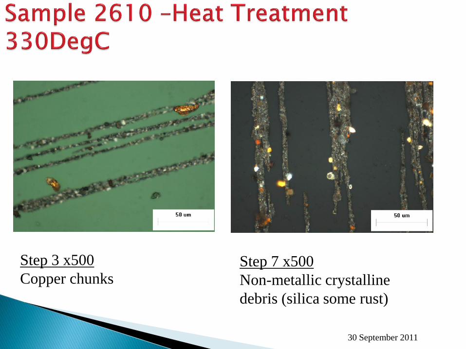
Step 3 x500
Copper chunks Step 7 x500
Non-metallic crystalline
debris (silica some rust)

30 September 2011
Step 9 x500
Fatigue Particle
Step 9 x500 – After Heat
Low Alloy steel fatigue
particle

30 September 2011
Step 9 x500 After Heat
Cast Iron fatigue chunk possibly from case hardened
gear pitch line

30 September 2011

30 September 2011
30 September 2011
30 September 2011
Thank you for your time.