Embed Size (px)
Citation preview

SwRIIndependent Research
& DevelopmentFabrication Test & Evaluation
ServicesProduct & Process
Design
Oil & Gasand
O�shoreTechnologies
2021
®

Southwest Research Institute® (SwRI®), founded in 1947, is one of the oldest and largest independent, nonprofit, applied R&D organizations in the United States.
2
SwRI provides contract research and development services for industrial and government clients. With more than 2.3 million square feet of laboratories and offices, SwRI’s nine technical divisions provide multidisciplinary, problem-solving services to research and physical sciences projects. Total revenue in 2018 was $583 million.
The staff numbers more than 2,600, including 271 staff members with doctorates and 510 with master’s degrees. In 2018, staff members published 667 technical papers and made 680 technical presentations. We submitted 55 invention disclosures, filed 49 patent applications, and received 28 patent awards.
Internal funding of research enables the Institute to advance knowledge, increase technical capabilities, and expand our reputation as a leader in science and technology. In 2018, we initiated 84 new projects and funded more than $7 million in internal research.
In 2018, SwRI managed 14 multi-client programs, including four oil and gas consortia, designed to allow organizations to pool their R&D dollars for pre-competitive research. For example, the Permian Basin joint industry program is characterizing the distribution, mechanisms, and orientations of faults and fractures related to tectonic events. Results help oil and gas industry members develop successful drilling and production strategies.
The Mechanical Engineering staff develops mechanical solutions for multiple industries. From power utilities to the oil and gas industry, we are proud to improve efficiency and productivity through expertise in engineering dynamics, structures, materials, and fluids systems. Our mission is to improve the safety, reliability, efficiency, and life of new or existing mechanical components and systems for the benefit of our clients.
Since 1971, SwRI has earned 43 R&D 100 awards for developments recognized by R&D Magazine as among the 100 most significant technical accomplishments of the year.
THINK SwRI … for all your technical needs and challenges.

O i l & G a s a n d O f f s h o r e T e c h n o l o g i e s 2 0 1 9
THINK SwRI ...our technologies can solve your problems
Southwest Research Institute Overview ....................................................................................................2
SwRI Contacts for Expert Technology Solutions .....................................................................................4
Oil and Gas Industry Support..........................................................................................................................6
Corrosion Testing and Monitoring ................................................................................................................7
Multiphase Flow Facility ....................................................................................................................................8
Sand Control Screen Coupon Erosion Testing..........................................................................................9
Metering Research Facility ...............................................................................................................................10
Fluids Engineering CFD Services ...................................................................................................................11
Test Services for Offshore Insulation and Corrosion Protection Systems ....................................12
Valve and Flow Component Testing .............................................................................................................13
Polymer High-Pressure High-Temperature Exposure Testing ...........................................................14
Deep Ocean Pressure Simulation Testing ..................................................................................................15
Pressure Vessel Design and Fabrication .....................................................................................................16
Marine Systems .....................................................................................................................................................17
Fitness-For-Service ..............................................................................................................................................18
Structural Engineering .......................................................................................................................................19
Surface Engineering ............................................................................................................................................20
Physical Environmental Testing Services ...................................................................................................21
Magnetostrictive Technology for Inspection of Pipelines and Tank Floors.................................22
Guided Wave Systems for Screening Heat Exchanger Tubing ..........................................................23
Precision Machining and Fabrication Services ........................................................................................24
NASGRO Fracture Mechanics and Fatigue Crack Growth Analysis Software .............................25
From Deep Sea to Deep Space ........................................................................................................................26
3

4
SwRI Contacts for Expert Technology Solutions
Mechanical Testing & Corrosion Fatigue Structural Engineering
Sensor Systems & NDE Technology
Multiphase Flow & Component Testing
Structural Mechanics & Analysis
Clinton J. ThwingManager
Sensor Systems & NDE Technology
Carl F. Popelar, PhDManager
Mechanics & Materials210.522.4213
Joseph W. Cardinal, PEStaff Engineer
Structural Analysis, Fatigue & Fracture
Timothy A. Fey, PEDirector
Structural Engineering210.522.3253
Fabrication
Mark W. WaldronManager
Fabrication Services210.522.6967
Surface Engineering
Kent E. Coulter, PhDSenior Program Manager
Surface Engineering & Thin Films
Ronghua Wei, PhDProgram Director
Surface Engineering & Material Chemistry
James H. FeigerPrincipal Engineer
Mechanics & Materials210.522.6881
Brian Somerday, PhDPrincipal Engineer
Environment-assisted Cracking
Steven T. GreenInstitute Engineer
Cuttings Fall Velocities, Flow Modeling & Simulation
Russell C. BurkeyProgram Manager
Mechanical Design, Hardware Development, Flow Testing
Christopher W. JowersManager
Valve Testing, High Concentration Slurries,
Mechanical Design210.522.4221
Terrence A. GrimleyStaff Engineer
Natural Gas Flow Measurement & Flow Meter Calibration
Shane P. SiebenalerDirector
Valve Testing, Leak Detection
Angel M. WilemanManager
Fluid Dynamics210.522.2657
Kevin R. SupakSenior Research EngineerMultiphase Flow Testing
& Simulation210.522.2350
Amy B. McCleney, PhDResearch Engineer
Multiphase Flow Testing210.522.6439
Seth M. NelsonResearch Engineer
Flow Characterization210.522.3312
Sergey A. Vinogradov, PhDStaff Engineer
Sensor Systems & NDE Technology
Adam C. Cobb, PhDPrincipal Engineer
Sensor Systems & NDE Technology
R. Craig McClung, PhDProgram Director
Structural Analysis, Fatigue & Fracture
Kyle W. RobinsonSenior Research Engineer
Structural Analysis, Fracture Mechanics
Reliability & Integrity
Ben H. Thacker, PhD, PEExecutive Director
Reliability-Based Design & Analysis
Barron J. Bichon, PhDManager
Computational Materials Integrity
David S. RihaStaff Engineer
Probabilistic Analysis & Uncertainty Quantification

O i l & G a s a n d O f f s h o r e T e c h n o l o g i e s 2 0 1 9
5
SwRI Contacts for Expert Technology Solutions
Offshore Products Development & Testing
Fluid Machinery Systems
Propulsion & Energy Machinery
Environmental Performance of Materials
Eugene L. BroermanPrincipal Engineer
Acoustic, Vibration, Pulsation & Flow Measurement Dynamics
Timothy C. Allison, PhDManager
Rotating Machinery210.522.3561
tim.allison @swri.org
Hector A. DelgadoManager
Machinery Services210.522.2960
James F. DanteManager
Environmental Performance of Materials
Environmental Testing
Jenny L. FerrenManager
Product Assurance & Structural Dynamics
Fire Technology
Matthew S. Blais, PhDDirector
Fire Technology210.522.3524
Leonardo J. Caseres, PhDSenior Research Engineer
Mechanics & Materials210.522.5538
David L. Ransom, PEDirector
Machinery Department210.522.5281
Benjamin A. White, PEManager
Mechanical Vibration & Structural Design
Elizabeth A. Trillo, PhDPrincipal Engineer
Materials Performance & Characterization
Gustavo J. VasquezSenior Research Engineer
HPHT Environmental Performance of Materials
Grant O. MusgroveManager
Machinery CFD210.522.6517
Aaron M. McClung, PhDManager
Power Cycle Machinery210.522.2677
Christopher L. Storey, PEManager
Ocean Simulation & Product Testing210-522.3992
Joseph E. Crouch, PEProgram DirectorProduct Design,
Fabrication & Testing210.522.4295
Alan P. SteinerPrincipal Specialist
Ocean Simulation & Product Testing210.522.3771
Paul A. GarzaSenior Research Engineer
Ocean Simulation & Product Testing210.522.5112
Matthew W. JamesProgram Manager
Product Test & Evaluation
Eric S. Thompson, PEProgram Manager
Structures & Engineering
Robert J. DuranSenior Research
EngineerMarine Structures &
Engineering210.522.3371
Fang Pan, PhDResearch EngineerMarine Structures
& Engineering 210.522.6341

T H I N K S w R I
For more than 50 years, SwRI has supported the oil and gas industry with structural engineering services including drilling systems, completion systems, and transportation systems.
Capabilities •Solid modeling
•Computational fluid dynamics
•Finite element analysis
•Testing and instrumentation
•High and low temperature test environments
•Probabilistic methods
•Fatigue and fracture mechanics
•Life prediction methods
•Full-scale and large-scale structural testing
•Machining and fabrication
Industry Experience •Riser fatigue analysis
•LNG tanker analysis
•Drilling/production equipment testing
•Riser system failure assessment
•Drilling platform structural analysis
•Pipe and hose testing
•Proof pressure testing
•Cyclic and pressure impulse testing
Facilities •Fabrication shop
•Structures laboratory
•Tension and compression load frames
•Torsion tower and water tank
•Deep ocean simulation laboratory
•High-pressure high-temperature laboratory
6
Functional testing of full-size subsea
equipment
Investigation of failure mechanisms for a
buoyancy can design used in the Gulf of
Mexico
Joseph E. Crouch, [email protected]
Matthew W. James [email protected]
structural-engr.swri.org
Oil & Gas Industry SupportDesign, Fabrication, and Testing

SwRI has over 25 years of experience in assessing corrosion and materials failure, and is internationally recognized for corrosion testing and monitoring of concrete and steel components.
Wireless Fluidized Sensor Technology SwRI has developed and tested a robust and inexpensive fluidized sensor designed to flow with the gas stream in non-piggable lines. The concept is applicable for natural gas distribution systems and liquid pipelines.
Concrete Corrosion Monitoring Technology SwRI developed an integrated concrete transducer prototype capable of measuring chloride ion concentration, pH, localized and uniform corrosion rates, and resistivity.
Integrated Corrosion Evaluation Technology The SwRI-developed integrated corrosion evaluation (ICE) system is used to transmit sensor data through a wireless Wi-Fi or USB cable connection to PC software.
Coating Degradation Sensor Technology SwRI engineers have developed a multi-sensor system for in-situ, real-time monitoring of the degradation of protective coatings and incipient substrate metal corrosion on steel bridges and vehicles to provide automatic warnings of coating/structure problem conditions prior to visible indications.
Electrochemical Testing The Environmental Performance of Materials (EPM) Laboratory capabilities include testing and evaluation of corrosion rates, galvanic corrosion, uniform corrosion, impedance, and pitting. The lab routinely performs ASTM, NACE, and other standardized testing.
Sour Gas Testing H2S / sour gas testing is caried out in both gaseous and aqueous environments in configurations including static, slow strain rate, tensile, fatigue, and creep. The test environment may also include CO2, CH4, and/or N2.
Atmospheric Corrosion TestingEnvironmental conditions are simulated within two cyclic corrosion chambers to determine how factors such as humidity, precipitation, and heat influence galvanic effects, pitting, stress corrosion cracking, coatings performance, and materials degradation.
Coating Development for Reinforced Concrete and Steel Structures SwRI has developed a synthetic diamond-like carbon (s-DLC) coating that can be deposited onto steel from a plating bath at low temperatures and normal atmospheric pressures.
Corrosion Testing and Monitoring
Wireless fluidized sensor
HPHT testing to determine
mass loss corrosion effects under gaseous environments
James F. [email protected]
Elizabeth A. Trillo, [email protected]
corrosion.swri.org
Prototype transducer for
monitoring corrosive
conditions in concrete
O i l & G a s a n d O f f s h o r e T e c h n o l o g i e s 2 0 1 9
7

T H I N K S w R I
8
SwRI offers unique facilities and capabilities to help oil and gas companies advance technology for topside and subsea applications.
Facility Capabilities Fluids
•Natural gas, nitrogen
•Crude oil, condensate, refined oil
•Fresh water, saltwater
•Oil and water combined
•Chemical injection
Operating Conditions
•Pressure 100–3,600 psig
•Temperature 40–120°F
•Gas volume fraction 0–100%
•Water cut 0–100%
Instrumentation
•Various gas and liquid reference meters
•Temperature, pressure, differential pressure
•Gas volume fraction (GVF)
•Water cut
•Deposition and holdup monitoring by gamma ray densitometer
•High-pressure flow visualization
Research Areas Multiphase Flow
•Characterization
•Hydrodynamics
•Modeling
Equipment Testing and Qualification
•Multiphase/wet gas meters
•Sampling systems
•Multiphase pumps
•Gas-liquid separators
•Phase fraction instrumentation
Flow Assurance
•Hydration
•Wax deposition
•Gelled crude oil yield strength
Gas-liquid separator performance
evaluation at high pressure
0.00
5,000
10,000
15,000
20,000
25,000
30,000
35,000
40,000
0.5 1.0 1.5 2.0 2.5
Gas Flow Rate [acfs]
GVF=0.10GVF=0.25
GVF=0.50
GVF=0.60
GVF=0.70
GVF=0.80
GVF=0.90
Liq
uid
Flo
w R
ate
[bp
d]
Combined flow rates of gas and liquid within 2.4 acfs
Kevin R. Supak [email protected]
mff.swri.org
Multiphase Flow Facility
8

Sand Control Screen Coupon Erosion Testing
New metal mesh screen
Eroded metal mesh screen
Typical screen assembly
components
Since developing an erosion test for sand screen coupons in 1998, SwRI has conducted hundreds of tests simulating erosion due to passed particles. Dedicated test facilities include two test rigs for erosion tests on sand screen coupons. SwRI also offers testing services on customized setups.
Applications •Comparing different products intended for the same application
•Understanding the effect of fluid velocity and viscosity
•Evaluating new or improved screen designs
•Understanding the effect of erosion in production and injection operations
•Simulating gravel packs and perforations
Standardized Testing •Erosion information available in two days
•Particle concentration up to 10,000 ppmw
•Flow rate 12 to 42 gpm (8,000 to 28,000 bpd/ft2)
Custom Testing •Flow rates up to 80 gpm
•Particle size
•Various assembly combinations
• Jet impingement testing
•Effect of material type
•Different screen coupon assembly dimensions (e.g., stacks up to 2 inches thick, customized coupon holders)
•Test fluid (allowing for variations in viscosity and density)
•Customized inlet and outlet geometries to simulate specific applications (e.g., gravel packs and perforations)
9
Seth M. Nelson [email protected]
mff.swri.org
O i l & G a s a n d O f f s h o r e T e c h n o l o g i e s 2 0 1 9

T H I N K S w R I
10
As the only facility of its type in North America, the SwRI Metering Research Facility is an internationally recognized center of excellence for natural gas flow measurement accuracy, rangeability, controllability, and traceability.
Capabilities •Flow meter design and development
•Flow meter testing and calibration (traceable to National Institute of Standards and Technology)
•Flow meter station design, consultation, layout and optimization
•Field meter diagnostics and troubleshooting
•Gas sampling quality and gas consultation
•Gas measurement personnel training
Flow Test Systems •High Pressure Loop (HPL) for high pressure/volume metering applications (pipe diameter 2–20 inches, pressure 165–1,100 psig)
•Low Pressure Loop (LPL) for low pressure/volume metering applications (pipe diameter 1–8 inches, pressure 20–190 psig)
•Both closed, recirculating flow loops operated from a single control center
Expert Services •On-site fuel flow measurement audits
•Training on meter station design
•Engineering, testing, and analysis of all meter types and sizes
•On-site meter station troubleshooting
User Benefits •Replication of field conditions
•Meter calibration accuracy better than 0.2%
•Field condition test bed for proving meters
•On-line analysis of test data
•Quick turnaround of tests
•Cost savings
High-Technology Natural Gas Flow Measuring Services
Metering Research Facility
The mass-time primary standard is used to calibrate
working flow standards.
Terrence A. Grimley [email protected]
mrf.swri.org
Flow meter calibrations include ultrasonic, Coriolis, turbine, and orifice meters.
The MRF is a recirculating, high-
pressure natural gas flow facility used
for testing pipeline components.

Amy B. McCleney, [email protected]
Steven T. [email protected]
fluidflowcfd.swri.org
11
Fluids Engineering CFD ServicesComputational fluid dynamics (CFD) uses numerical methods to analyze physical phenomena involving fluid flow. Multiphase flows, in particular, present many challenges due to intricate mixing and interfacial transients.
SwRI engineers have more than 30 years of experience conducting research for a diverse range of clientele problems. Using state-of-the-art software in combination with parallel processing capabilities, SwRI strives to provide timely solutions for development and operational challenges.
Applications •Oil and gas production/transport
•Pipeline accidental spill and leak assessment
•Space vehicle propellant dynamics
•Environmental flows
•Combustion
•Medical device operation
•Food processing
•Fluid-structure interactions
Advantages of Using CFD •Rapid analysis with reduced resource requirements
•Fewer prototype iterations
•Corroboration of experimental results
• Investigation of parameters not obtainable via traditional experimental techniques (due to time scales, impracticality of sensor placement, visual obstructions, etc.)
Clients •Oil and gas industry
•Space science
•Medical community
•Food processing industry
•Environmental agencies
•Nuclear Regulatory Commission
SwRI-developed emulsion model used to predict batch
separation of oil-water mixtures
O i l & G a s a n d O f f s h o r e T e c h n o l o g i e s 2 0 1 9
Porous boundary analysis using model developed from
experimental data in the same multiphase SwRI project
Simulation of landslide-generated tsunami event from Lituya Bay in Alaska

T H I N K S w R I
12
Test Services for Offshore Insulation and Corrosion Protection SystemsSwRI provides facilities and test capabilities for the offshore industry and manufacturers of insulation and corrosion protection materials.
Capabilities •Simulated service tests
• Insulation materials testing
•Short/long term exposure testing
•Thermal testing of insulation
•Mechanical properties tests
Experience •Evaluation of subsea wet insulation materials and application procedures to client specifications
•Simulation of subsea conditions to evaluate mechanical and thermal integrity of insulation materials
•Setup of tests and procedures
•Test results used to determine:
◦ Effectiveness of different types and thicknesses of wet insulation in subsea conditions
◦ Cool-down periods
◦ Verification of thermal, mechanical, and application characteristics of product
◦ Mechanical properties of materials for comparative analysis (exposed and unexposed samples)
◦ Tensile/elongation, density, hardness, hydrostatic crush, FTIR, DMA
Facilities •Underwater Engineering Laboratory with hydrostatic test chambers that can be used to simulate temperatures and ocean depths >10,000 feet
•Hot liquid/air flow units to internally heat pipe samples subjected to external pressure or ambient conditions
•Multiple environmental chambers of various sizes and ratingsSimulated service test in
13-inch chamber rated for 30,000 psi and 650˚F
Subsea simulated pipe sample for testing in
chilled salt water and heated internally
Joseph E. Crouch, [email protected]
Christopher L. Storey, [email protected]
deepoceansimulation.swri.org

13
With more than 40 years of experience in testing of valves and other flow components, SwRI is a world leader in providing independent validation testing of flow products for a variety of industries.
SwRI’s valve test facility was built specifically to evaluate production valves as recommended in API 6A. The facility can accommodate up to 20,000-psi rated valves and actuators.
Multiple high-pressure gas boosters and pressurization loops were designed and built by SwRI with safety in mind. Used during temperature extreme test phases, insulated environmental chambers maintain temperatures between 400˚F and –200˚F. Custom manifolds and plumbing can be added.
Capabilities •Testing from full liquid nitrogen immersion up to elevated temperatures (–320˚F to 800˚F)
•Design and fabrication of custom thermal chambers
•Cryogenic testing to BS 6364 or customer specification
•Fugitive emissions testing to ISO 15848 or customer specification
•Flow coefficient (Cv) testing with water or nitrogen
•Gas blowdown and gas lift testing
•Slurry testing
•Low-cost testing at field or near-field conditions
•Operating pressures up to 3,000 psig
•Flow rates up to 230 MMSCFD
•Differential pressures >2,000 psi
•Gas source volume 1,125 ft3
API 6A-PR2 Tests •Force measurement open/close
•Dynamic cycling at ambient temperature
•Maximum/minimum temperature cycling
•Pressure/temperature cycles
•Ambient temperature seal tests
•Dual-zone temperature control
Standardized and Specialized Testing Services •Valves (process, production, subsea, gas lift, safety, and control)
•Downhole tools
•Piping
•Gaskets and seals
•Pumps
•Actuators and eductors
•LNG products
Valve and Flow Component Testing
Shane P. [email protected]
Christopher L. Storey, PE [email protected]
valvetest.swri.org
High-pressure test conducted within large containment chamber to allow for safe operation
Valve and hydraulic actuator assembly
undergoing low-temperature
(–50°F) test
O i l & G a s a n d O f f s h o r e T e c h n o l o g i e s 2 0 1 9

T H I N K S w R I
Polymer High-Pressure High-Temperature Exposure Testing
To help clients meet new emerging material performance requirements for testing of nonmetallic materials (thermoplastics, elastomers, and composites) and present accurate results following HPHT exposures, SwRI uses a broad selection of standardized testing methods in compliance with API and ASTM standards.
SwRI has developed unique HPHT capabilities including conditions up to 20,000 psi and 650˚F for testing in aggressive toxic environments.
High-Pressure High-Temperature Autoclave Testing
•10,000 ft2 Autoclave Testing Laboratory with 34 autoclaves dedicated to various HPHT tests
•Standard and customized exposure tests to assess the performance of polymeric and composite materials after exposure to HPHT toxic environments
•Specimen types including standardized dumbbell-shape, O-ring, adhesion, and compression button
•Testing in a wide variety of fluids charged with an array of H2S / CO2 / CH4 mixture combinations
• Immersion testing and rapid gas decompression testing performed and certified for nonmetallic materials in valves or drilling equipment
•HPHT testing of sealing material in full-size components of drilling, wellhead, and Christmas tree equipment
•ASTM standards: D395, D471, D543, D695, D792
Mechanical Testing •6,500 ft2 Mechanical Engineering Performance Laboratory with 36 tensile test frames dedicated to mechanical testing of materials
•Standard and customized tests to assess the performance of polymeric dumbbell specimens before and after an exposure test
•ASTM standards: D412, D429, D638, D790, D2240
SwRI’s HPHT autoclaves are used to expose polymeric compounds to simulated hazardous environments.
Polymeric and rubber specimens are
stamped out of flat plates with certified
cutting dies.
Gustavo J. Vasquez [email protected]
corrosion.swri.org
14

15
Deep Ocean Pressure Simulation Testing
With more than 50 years of experience in offshore and marine technologies, SwRI offers deep ocean pressure simulation testing services that provide a final check of quality and operational integrity for clients including oil producers, subsea component and pipeline manufacturers, and the U.S. Navy.
Ocean Simulation Laboratory •More than 10,500 ft2 of climate-controlled laboratory space
•Additional outdoor test facilities
•Deep ocean test chambers ranging from 90 inches inside diameter, 20 feet deep to 16 inches inside diameter, and up to 30,000 psig
Services •Engineering design verification
•Product evaluation
•Prototype construction
•Design and fabrication of special test fixtures for client-specified requirements
•High-speed and still underwater photography
Testing • Internal and external hydrostatic pressure tests
•Stress analysis and acceptance tests
•Operational tests requiring electrical and hydraulic penetrations
•Collapse and burst tests on API steel pipe casing, fiberglass pipe, titanium, and stainless steel pipe
•Testing of prototype equipment, pressure housings, subsea instrumentation, cables, connectors, oil field production and safety equipment
Christopher L. Storey, [email protected]
Alan P. [email protected]
deepoceansimulation.swri.org
Diving suit subjected to hydrostatic
pressure test
Main pressure laboratory housing more than 10 deep
ocean pressure chambers
O i l & G a s a n d O f f s h o r e T e c h n o l o g i e s 2 0 1 9
Hydrostatic Pressure Tests Ocean Simulation Lab
Maximum ID (inches) Max Operation (psi)
90 2,50050 6,00048 3,30030 10,00019 12,000
16, 13 (multiple) 30,00015 20,00012 20,0008 20,0002 60,000

T H I N K S w R I
16
SwRI designs, analyzes, and fabricates pressure vessels subjected to both internal and external pressure loadings, including:
•Hyperbaric chambers
•Deck decompression chambers
•Casing collapse chambers
•Submersible hulls
•Scale models of submarine hulls
•Undersea communications and equipment chambers
•Large diameter subsea simulation chambers
•Pressure vessels for specialized research programs
Capabilities •Design, analysis, and fabrication of pressured vessels using:
◦ ASME B&PV Codes, Section VIII, Divisions 1–3
◦ ASME Pressure Vessels for Human Occupancy
◦ American Bureau of Shipping Rules
◦ U.S. Navy Design Rules
◦ U.S. Navy Fabrication Procedures
•Design of structures and load frames using AISC Specification for the Design, Fabrication, and Erection of Structural Steel Buildings
Experience •Hull for U.S. Navy next-generation submarine rescue system
•Quarter-scale model of U.S. Navy Seawolf Class attack submarine
•Casing collapse chambers with internal pressure ratings of 30,000 psig
•Research vessel with sapphire viewports with pressure rating of 50,000 psig
•Hyperbaric chambers
•6,500 msw research submarine
Pressure Vessel Design and Fabrication
Pressure hull for U.S. Navy next-generation
submarine rescue system designed, built, and
tested at SwRI
Deep ocean test chamber (50-inch inside diameter,
24 feet long, 6,500 psi) at SwRI
Matthew W. [email protected]
Joseph E. Crouch, [email protected]
structural-engr.swri.org

17
Marine SystemsDesign, Analysis, Development, and Testing
SwRI built the 100-foot-long Kokanee submarine to simulate the acoustic
and hydrodynamic characteristics of the Seawolf Class attack
submarine.
SwRI converted this deck decompression chamber from a double-lock to a triple-lock configuration and upgraded its
rating from 900 to 1,200 feet of salt water (fsw).
SwRI has supported the marine and offshore industries for more than 50 years. Expert staff provide design, analysis, and experimental or numerical modeling to achieve optimum results for marine, life support, and salvage systems.
Capabilities Marine Systems
•Manned, unmanned, remotely operated and autonomous vehicle systems
•Surface and subsea structures and structural systems
•Manned and unmanned pressure vessels
•Deep ocean pressure vessels
•Large, full-scale, and small-scale models
•Vehicle propulsion and hydrodynamics
•Power generation and transfer
•Subsea data transfer
Life Support Systems
•Closed and semi-closed circuit diving systems
•Surface-supplied diving systems
•Saturation diving systems
•Scuba diving systems
•Damage control / first responder breathing gas systems
•Hyperbaric medical treatment systems
•Thermal protection
Marine Salvage
•Marine salvage engineering
•Petroleum offloading
•Surface-supplied diving (air and mixed gas)
•Saturation diving (air and mixed gas)
Joseph E. Crouch, [email protected]
Matthew W. [email protected]
structural-engr.swri.org
O i l & G a s a n d O f f s h o r e T e c h n o l o g i e s 2 0 1 9

T H I N K S w R I
18
Fitness-For-ServiceFitness-For-Service assessment is a multidisciplinary engineering evaluation performed to demonstrate the structural integrity of an inservice component. SwRI uses the guidelines in API 579-1/ASME FFS-1 and FITNET to determine if pressurized equipment containing flaws identified by inspection can continue to operate safely.
Flaws Assessed • Crack-like flaws including environmental cracking, delaminations, dents, and gouges
• General and localized corrosion
• Widespread and localized pitting
• Blisters and hydrogen damage
• Weld misalignment and shell distortions
◦ Employs nondestructive examination engineering methods include ultrasonics, electromagnetics, magnetostrictive sensor-based guided waves, and x-rays to detect, characterize, and size flaws or quantify the amount of damage
◦ Uses probabilistic analysis to determine the dependence of the safety margin on the variations and uncertainties of the input parameters and estimate the probability of failure
◦ Other methods include Section VIII, Division 3 of ASME BPVC, and USAF/FAA Damage Tolerance Approach
Engineering Services • Structural engineering analysis of static, dynamic, or thermal loading
• Fracture mechanics engineering using NASGRO® (see page 25) to assess crack-like flaws for fracture and fatigue crack growth
◦ Uses the NASGRO crack growth equation, which includes the near-threshold and near-instability regions of crack growth and accounts for stress ratio effects
◦ Includes a material database of crack growth rate and fracture toughness data
◦ Applies materials engineering to identify material damage mechanisms, establish corrosion/erosion rates, and determine material properties including strength, crack growth rate, and fracture toughness
Joseph E. Crouch, [email protected]
Kyle W. [email protected]
structural-engr.swri.org
Finite element analysis of a pressure vessel
Ultrasonic (top) and eddy current (bottom) imaging of a surface crack
in a cladded material

19
Timothy A. Fey, [email protected]
Joseph E. Crouch, [email protected]
structural-engr.swri.org
Structural Engineering Experienced structural engineering specialists at SwRI design, analyze, fabricate, and test structural systems and components over a broad spectrum of industries including aerospace, marine, offshore, petrochemical, building, highway, and transportation.
Capabilities •Structural design and redesign to improve performance and lifetime
•Structural analysis
•Test planning, buildup, and instrumentation
•Test execution and data interpretation
•Field testing and service environment evaluation
•System fabrication and assembly
•Compliance testing and engineering stress screening
•Damage tolerance analysis
•Fatigue and fracture analysis
•Probabilistic risk analysis
Experience •Structural analysis of aircraft, marine, offshore, and other systems
•Test planning, test buildup, instrumentation, test execution, and data collection and analysis of complex structures under static, fatigue, and other harsh loading environments
•Testing of high-strength steel, aluminum, acrylic, and composite hulls and housing for the U.S. Navy and commercial submersible/diving system companies
•Structural enhancements and life extension of aircraft, marine, and other mechanical systems
•Full-scale aircraft static and fatigue testing
Facilities •High bays with overhead bridge cranes for fabricating and welding pressure vessels, submersibles, load frames, and other structures
•56-foot-high Heavy Article Testing Facility
•17,000 ft2 Mechanical Fabrication Center
•CAD/CAM programming control room
•Large inspection room to perform quality assurance measurement control
Finite model stress analysis of a fighter-trainer aircraft wing
Dynamic Impact Test Facility with concrete runway, large pendulum, large buried and surface-mounted reaction
masses, and drop tower to simulate various types of dynamic impact, drop, and crash events
O i l & G a s a n d O f f s h o r e T e c h n o l o g i e s 2 0 1 9

T H I N K S w R I
20
Plasma-enhanced magnetron sputtering
Surface Engineering
Surface engineering at SwRI is a coating service for the practical treatment of materials and components using energetic ion beams to protect material surfaces from corrosion, wear, fatigue failure, fretting, and oxidation. Processes include ion implantation of gaseous ions and ion beam-assisted deposition (IBAD) of metals, ceramics, and diamond-like carbon (DLC).
Experience •Bulk and surface modification
•Thin film and thick coating deposition
•Process enhancement
•New material development
•Specialized testing and characterization
•Diamond-like carbon (0.1–30 μm)
•Superhard, ultra-thick nanocomposite coatings (>45 GPa, 10–500 μm) , nanocrystalline nitrides in amorphous SICxNy, including TiSiCN, CrSiCN, TiAlSiCN, TaSiCN
•Multifunctional nanocomposite coatings
•Multilayer and super lattice coatings
•Traditional hard tribological coatings including TiN, CrN, AlTiN, AlCrN
•Oxide coatings with high and low refractive index
•Spray coatings
•Oleophobic coatings
•Hydrophobic coatings
•Web coatings
Applications •Production/transport piping
•Valves
•Connectors
•Screens
Facility Capabilities •Vacuum surface modification
•Atmospheric pressure plasma modification
•Wet chemistry-based surface modification
•Coating of advanced materials
Kent A. Coulter, [email protected]
Ronghua Wei, [email protected]
surfaceengineering.swri.org
Atmospheric plasma
pressure jet
Pre-production coater

21
Physical Environmental Testing Services
SwRI provides research, development, and independent testing services to a broad client base to ensure the functionality, structural integrity, and environmental compatibility of systems and components subjected to adverse storage, transportation, and operating environments.
The Physical Environmental Testing Laboratory staff provides technical evaluations and assistance, test design and tailoring, and standardized testing to a variety of government and industry standards. Personnel are specially trained to conduct nuclear component qualification and testing for the U.S. Department of Defense and NASA.
Facility Capabilities •Unique facilities in one location
•Simulated earthquake vibration
•Ground or air transportation vibration
• Installation and handling shock
•Temperature and humidity control
•High-altitude transportation and operation
•Airborne contamination
•Acoustic noise measurement
•Wind and rain
•Corrosive atmosphere
•UV exposure and solar loading
•Certified under ISO 9001:2015 and ISO 17025 accredited
Additional Capabilities •Remote client monitoring of equipment being tested
•Remote monitoring of test chamber performance
•Accommodation of large equipment for temperature, altitude, and earthquake testing
Government and Industry Standards •National (ASTM, IEEE, ASME)
•Military (MIL-Spec)
• International (IEC, ISO)
•Telecom (Telcordia, UL, NEBS, ETS)
Equipment is placed in environmental chambers to evaluate performance in various temperature and
humidity conditions.
Jenny L. Ferren [email protected]
The SwRI Physical Environmental Testing Laboratory contains multiple environmental simulation facilities.
O i l & G a s a n d O f f s h o r e T e c h n o l o g i e s 2 0 1 9
T H I N K S w R I
22
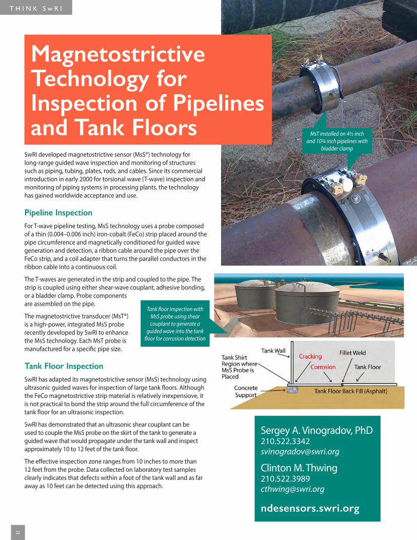
Magnetostrictive Technology for Inspection of Pipelines and Tank Floors
SwRI developed magnetostrictive sensor (MsS®) technology for long-range guided wave inspection and monitoring of structures such as piping, tubing, plates, rods, and cables. Since its commercial introduction in early 2000 for torsional wave (T-wave) inspection and monitoring of piping systems in processing plants, the technology has gained worldwide acceptance and use.
Pipeline InspectionFor T-wave pipeline testing, MsS technology uses a probe composed of a thin (0.004–0.006 inch) iron-cobalt (FeCo) strip placed around the pipe circumference and magnetically conditioned for guided wave generation and detection, a ribbon cable around the pipe over the FeCo strip, and a coil adapter that turns the parallel conductors in the ribbon cable into a continuous coil.
The T-waves are generated in the strip and coupled to the pipe. The strip is coupled using either shear-wave couplant, adhesive bonding, or a bladder clamp. Probe components are assembled on the pipe.
The magnetostrictive transducer (MsT®) is a high-power, integrated MsS probe recently developed by SwRI to enhance the MsS technology. Each MsT probe is manufactured for a specific pipe size.
Tank Floor InspectionSwRI has adapted its magnetostrictive sensor (MsS) technology using ultrasonic guided waves for inspection of large tank floors. Although the FeCo magnetostrictive strip material is relatively inexpensiove, it is not practical to bond the strip around the full circumference of the tank floor for an ultrasonic inspection.
SwRI has demonstrated that an ultrasonic shear couplant can be used to couple the MsS probe on the skirt of the tank to generate a guided wave that would propagate under the tank wall and inspect approximately 10 to 12 feet of the tank floor.
The effective inspection zone ranges from 10 inches to more than 12 feet from the probe. Data collected on laboratory test samples clearly indicates that defects within a foot of the tank wall and as far away as 10 feet can be detected using this approach.
Sergey A. Vinogradov, [email protected]
Clinton M. [email protected]
ndesensors.swri.org
Tank floor inspection with MsS probe using shear couplant to generate a
guided wave into the tank floor for corrosion detection
MsT installed on 4½ inch and 10¾ inch pipelines with
bladder clamp
23
Guided Wave Systems for Screening Heat Exchanger Tubing
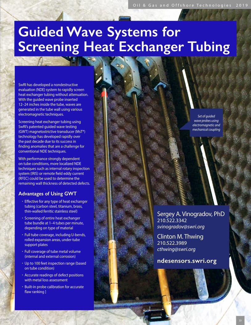
SwRI has developed a nondestructive evaluation (NDE) system to rapidly screen heat exchanger tubing without attenuation. With the guided wave probe inserted 12–24 inches inside the tube, waves are generated in the tube wall using various electromagnetic techniques.
Screening heat exchanger tubing using SwRI’s patented guided wave testing (GWT) magnetostrictive transducer (MsT®) technology has developed rapidly over the past decade due to its success in finding anomalies that are a challenge for conventional NDE techniques.
With performance strongly dependent on tube conditions, more localized NDE techniques such as internal rotary inspection system (IRIS) or remote field eddy current (RFEC) could be used to determine the remaining wall thickness of detected defects.
Advantages of Using GWT • Effective for any type of heat exchanger tubing (carbon steel, titanium, brass, thin-walled ferritic stainless steel)
• Screening of entire heat exchanger tube bundle at 1–4 tubes per minute, depending on type of material
• Full tube coverage, including U-bends, rolled expansion areas, under-tube support plates
• Full coverage of tube metal volume (internal and external corrosion)
• Up to 100 feet inspection range (based on tube condition)
• Accurate readings of defect positions with metal loss assessment
• Built-in probe calibration for accurate flaw ranking ]
Sergey A. Vinogradov, [email protected]
Clinton M. [email protected]
ndesensors.swri.org
Set of guided wave probes using
electromagnetic and mechanical coupling
O i l & G a s a n d O f f s h o r e T e c h n o l o g i e s 2 0 1 9

T H I N K S w R I
24
Precision Machining and Fabrication Services
The SwRI Machine Shop has extensive experience in the fabrication of complex precisioncomponents and parts, and operates under a quality program that meets the requirements for NASA and the U.S. Military. SwRI also operates several large fabrication and assembly facilities, the largest with 14,000 ft2 of floor space beneath 100-ton, 50-ton, and 25-ton bridge cranes with 40 ft of clear hook height.
CapabiltiesPrecision Machining
•CAD/CAM programming
•Milling machines
•Lathes with 5-axis mill turning center
•Sheet metal tools
•Grinders
•Electrical discharge machining (EDM)
•Water jet cutting
Welding
•Tungsten inert gas welding (TIG)
•Metal inert gas welding (MIG)
•Shielded metal arc welding (SMAW)
•Oxyacetylene welding (OAW)
•Titanium welding
• Inconel welding and cladding
On-Site Third-Party Validation and Verification (V&V)
Accreditations • ISO 9001
• ISO 14001
•ASME Certifications – U, U2, U3
•National Board Stamps – R, NB
•MIL-STD 278
Pressure Rescue Module System (PMRS) hull in
fabrication
Mark W. [email protected]
fabrication.swri.org
CNC programing control room
Precision machined
crankshaft for compressor on
the International Space Station
6-inch thick HY-100 steel door
frame for blast chamber

25
NASGROFracture Mechanics and Fatigue Crack Growth Analysis Software
NASGRO is a suite of programs used to analyze fracture and fatigue crack growth in structures and mechanical components. The software is developed jointly by SwRI and NASA, with additional support from the NASGRO Consortium and the FAA.
NASGRO consists of integrated modules with user-friendly graphical interfaces that:
•Calculate fatigue crack growth (FCG) life, critical crack size, and stress intensity factors (K)
•Store, retrieve, and curve-fit FCG and fracture toughness data
•Calculate Ks and stresses using 2-D boundary element method
NASGRO is the most widely used fracture mechanics and fatigue crack growth software in the world.
ModulesCrack Growth Example Features
•Over 75 different K solutions •Multiple crack growth equations
Material Property Example Features
•Search, retrieve, plot, and curve fit data •3,000 sets of FCG data
Additional Features
•NASGRO software compatibility with all Windows platforms •User support and training courses available
Recent Enhancements Examples of recent enhancements available in the current version 8.1 include:
•New pin-load K solutions for through and corner cracks in plates and lugs
• Improved finite width correction factors for pin-loaded holes
•Expanded geometry ranges for crack-at-hole weight function solutions
•New displacement-controlled K solution for corner crack in plate
• Improved robustness for inverse calculation options
Future Development Examples of plans for future versions include:
•Additional K solutions for lugs and structural sections
•New K solution for displacement-controlled surface crack
•Bivariant shakedown capabilities
•Superposition methods for time-dependent crack growth
•Additional K solutions for other unique geometries
K solution for two unequal corner cracks at
offset hole in a plate
NASGRO fatigue crack growth equation
Joseph W. Cardinal, [email protected]
R. Craig McClung, [email protected]
nasgro.swri.org
O i l & G a s a n d O f f s h o r e T e c h n o l o g i e s 2 0 1 9
T H I N K S w R I
1
2
3
4
DE139244
DE134605
D01
6501
_427
5
DE88086
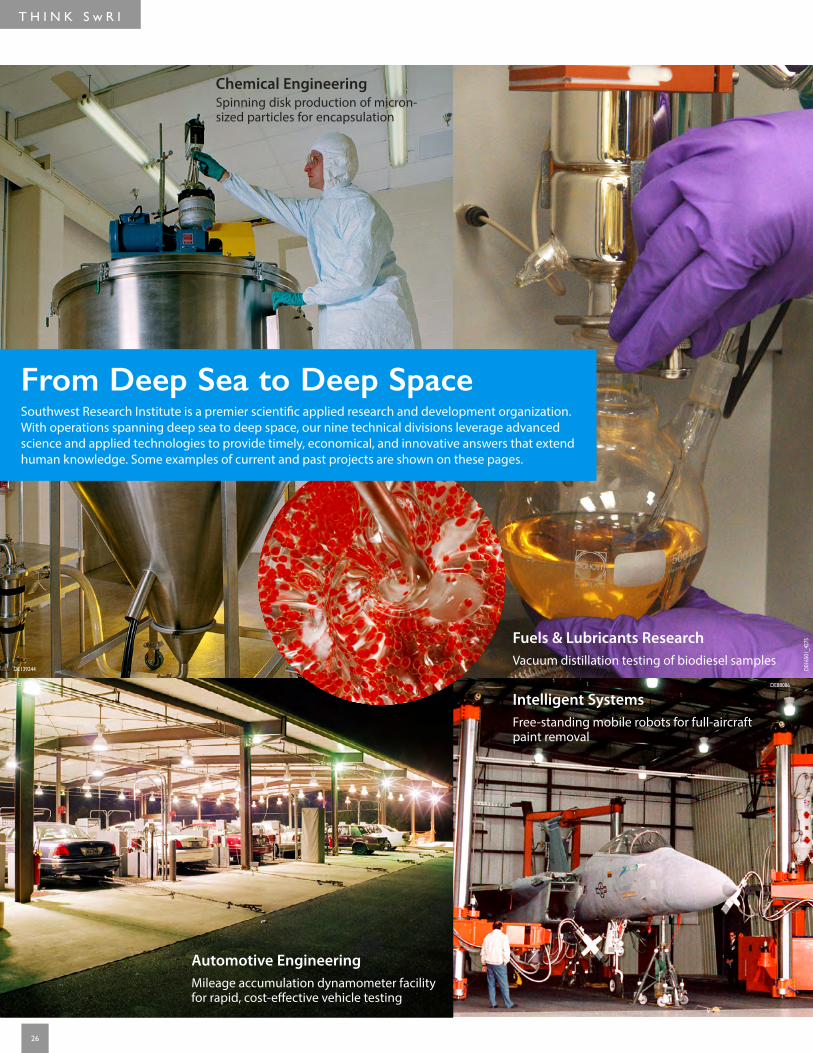
From Deep Sea to Deep SpaceSouthwest Research Institute is a premier scientific applied research and development organization. With operations spanning deep sea to deep space, our nine technical divisions leverage advanced science and applied technologies to provide timely, economical, and innovative answers that extend human knowledge. Some examples of current and past projects are shown on these pages.
Chemical Engineering Spinning disk production of micron-sized particles for encapsulation
Automotive Engineering Mileage accumulation dynamometer facility for rapid, cost-effective vehicle testing
Fuels & Lubricants Research Vacuum distillation testing of biodiesel samples
Intelligent Systems Free-standing mobile robots for full-aircraft paint removal
26

O i l & G a s a n d O f f s h o r e T e c h n o l o g i e s 2 0 1 9
5
9
6
7
DE88086
D018211DE124318
Ado
beSt
ock_
1111
7596
3
D013636_6348
D021918 (image courtesy NASA)
Applied Physics Terahertz imaging and spectroscopy station developed for imaging and nondestructive inspection applications
Defense & Intelligence Solutions SwRI-developed antennas communicating with satellites to support worldwide tracking, combat identification, and situational awareness
Space Science & Engineering JUNO spacecraft orbiting Jupiter with payload including two SwRI-built science instruments
Mechanical Engineering SwRI-developed magnesium scaffold implant to improve and accelerate bone healing
Nuclear Technology Research to assure safe and environmentally responsible use of nuclear power
27

©2019 Southwest Research Institute. All rights reserved.
Like. Share. Follow. Listen.
swri.org
210.522.2122Fax 210.522.3496
An Equal Employment Opportunity/Affirmative Action Employer Race/Color/Religion/Sex/Sexual Orientation/ Gender Identity/National Origin/Disabled/Veteran Committed to Diversity in the Workplace
Designed & printed by SwRI MPS 18 0419 261156 tp