Embed Size (px)
Citation preview
Air Quality Monitoring Network Standard Operating Procedures for the
BAM 1020 PM 2.5 Monitors Confederated Tribes of the Colville Reservation
Prepared by Kris Ray
Air Quality Program Manager January, 2012
Author
APPROVED
2-7-/ L DateO~I~t"
////V ~
CTCR Air Quality Monitoring Network SOP
February 2012
ii
Table of Contents List of Figures ................................................................................................................................. v
List of Tables .................................................................................................................................. v
List of Abbreviation and Acronyms .............................................................................................. vi
Introduction ..................................................................................................................................... 1
Scope and Applicability .................................................................................................................. 1
Definitions....................................................................................................................................... 3
Health and Safety Warnings ........................................................................................................... 4
Personnel Qualifications ................................................................................................................. 5
Installation Procedures .................................................................................................................... 6
Unpacking, Inspection and Moving ............................................................................................ 6
Acceptance Testing ..................................................................................................................... 6
Power On and Warm Up; Page 15 .......................................................................................... 7
72 Hour Field BKGD Zero Test; Page 19 .............................................................................. 7 1Pages shown are for operation manual revision G; pages for revision H are different but the
sections are the same. .................................................................................................................. 7
Site Selection .............................................................................................................................. 8
Enclosure Selection ..................................................................................................................... 9
BAM Installation ........................................................................................................................ 9
Tools Needed for Installation................................................................................................ 11
Install BAM 1020 in Enclosure ............................................................................................ 12
Insert Inlet Pipe and Install Smart Heater ............................................................................. 12
Install Ambient Temperature and Barometric Pressure Sensors .......................................... 12
Install the PM 2.5 and PM 10 Inlet Separator Heads ............................................................ 13
Wiring and Plumbing ................................................................................................................ 13
Power to the Monitoring Sites .............................................................................................. 13
Power Connection to the BAM 1020 and Pump ................................................................... 13
Auxiliary Ground .................................................................................................................. 13
Connect the Pump Tubing and Control Signal Cables ......................................................... 13
Pump Muffler ........................................................................................................................ 13
Connect the Air Temperature and Barometric Pressure Sensor ........................................... 14
Connect the Smart Heater ..................................................................................................... 14
Install Enclosure Temperature Sensor .................................................................................. 14
CTCR Air Quality Monitoring Network SOP
February 2012
iii
Connect to a Data Logger ..................................................................................................... 14
Initial Setup and Configuration Check ..................................................................................... 15
Power On and Warm Up ....................................................................................................... 15
Keypad Functions and Screen Displays ................................................................................ 15
Loading Filter Tape............................................................................................................... 16
Perform a Self-Test ............................................................................................................... 17
Set the BAM Clock ............................................................................................................... 18
System Configuration Parameters......................................................................................... 18
Conduct a Self-Test, Initial Leak Check and Flow Calibration ................................................ 19
72 Hour Field BKGD Zero Test ........................................................................................... 19
Maintenance and Quality Control Procedures .............................................................................. 21
Monthly Maintenance and QC .................................................................................................. 22
Flow Verification .................................................................................................................. 22
Leak Check ........................................................................................................................... 23
Clean the Nozzle and Vane ................................................................................................... 23
Clean the Capstan Shaft and Pinch Roller Tires ................................................................... 24
Clean the PM10 Inlet.............................................................................................................. 24
Clean the Collector Assembly .............................................................................................. 25
Clean the Acceleration Assembly ......................................................................................... 25
Clean the SCCTM
and the VSCCTM
....................................................................................... 26
Check Error Log ................................................................................................................... 26
Digital Data Download ......................................................................................................... 27
Two Month Maintenance and QC ............................................................................................. 27
Replace Filter Tape ............................................................................................................... 27
Conduct Self-test ................................................................................................................... 27
Flow, Temperature and Pressure Calibration ........................................................................ 27
Verify the BAM 1020 Settings ............................................................................................. 29
Six Month Maintenance and QC............................................................................................... 30
Service Pump Muffler ........................................................................................................... 30
Test the Filter Temperature and RH sensors ......................................................................... 30
Test Smart Heater ................................................................................................................. 31
Twelve Month Maintenance and QC ........................................................................................ 31
72 hour Background Test ...................................................................................................... 31
Clean or Replace internal debris Filter ................................................................................. 31
CTCR Air Quality Monitoring Network SOP
February 2012
iv
Check the Membrane Span Foil ............................................................................................ 31
Perform Beta Detector Count Rate and Dark Count Test ..................................................... 32
Clean Inlet Tube .................................................................................................................... 32
Independent Audit ................................................................................................................. 33
Replace Lithium Coin Cell Battery ....................................................................................... 33
Twenty Four Month Maintenance ............................................................................................ 33
Rebuild Vacuum Pump ......................................................................................................... 33
Replace Nozzle O-rings ........................................................................................................ 33
Replace Pump Tubing ........................................................................................................... 33
Data Acquisition System............................................................................................................... 34
Data Validation and Quality Assurance ........................................................................................ 34
Quality Control Best Practices .................................................................................................. 34
Data Validation ......................................................................................................................... 34
Data Validation Steps ........................................................................................................... 36
Diagnostics and Troubleshooting ................................................................................................. 37
Consumables and Spare Parts ....................................................................................................... 37
References ..................................................................................................................................... 38
Appendices .................................................................................................................................... 39
CTCR Air Quality Monitoring Network SOP
February 2012
v
List of Figures
Figure 1: BAM 1020 Enclosure, Met One BX 903 ........................................................................ 9 Figure 2: Typical BAM 1020 Installation in an Enclosure, From Met One Operation Manual
Revision G .................................................................................................................................... 10
Figure 3: BAM 1020 Keypad Grouping and Main Menu Screen Display ................................... 16 Figure 4: Filter Tape Routing in the BAM 1020 .......................................................................... 17 Figure 5: The self-test status screen following a test with no errors. ........................................... 18 Figure 6: A cotton-tipped applicator and isopropyl alcohol are used to clean the BAM-1020
nozzle and vane ............................................................................................................................. 24
Figure 7: The PM10 inlet has two primary components, the Acceleration Assembly and the
Collector Assembly. ...................................................................................................................... 25 Figure 8: SCC™ and VSCC™ Particle Separator Components ................................................... 26
Figure 9: MULTIPOINT FLOW CALLIBRATION Screen ........................................................ 28
List of Tables
Table 1: Comparison of Two BAM 2010 PM2.5 Monitors ............................................................. 1
Table 2: Evaluation of the Nespelem BAM 2010 for FEM Configuration (updated July 2011) ... 3 Table 3: Acceptance testing procedures for the BAM 1020 ........................................................... 7
Table 4: Site Selection Specifications for the BAM 1020 .............................................................. 8 Table 5: Tools and Supplies for installing and operation of monitoring sites .............................. 11 Table 6: Wiring Connections Between the BX-596 AT and BP Sensor and the BAM 1020
Terminal Strip ............................................................................................................................... 14
Table 7: Wiring Connections Between the BX-592 AT Sensor and the BAM 1020 Terminal Strip
....................................................................................................................................................... 14 Table 8: Sample Screen Setting for the Nespelem and Inchelium BAM 1020 ............................ 18
Table 9: Calibrate Screen Settings for the Nespelem and Inchelium BAM 1020 ........................ 19 Table 10: Smart Heater Settings for the Nespelem and Inchelium BAM 1020 ............................ 19 Table 11: Met One Recommended Maintenance Items and Schedule, BAM 1020 ..................... 21
Table 12: Quality Control Action and Critical Criteria BAM 1020 ............................................. 22 Table 13: Verify BAM 1020 Settings ........................................................................................... 29 Table 14: Critical and operational data validation criteria for the Met One BAM ....................... 34 Table 15: Data Validation Steps for BAM 1020 .......................................................................... 36 Table 16: Suggested Consumable and Spare Parts to Keep Available ......................................... 37
CTCR Air Quality Monitoring Network SOP
February 2012
vi
List of Abbreviation and Acronyms 14
C Carbon 14
AT Ambient Temperature
AQP Air Quality Program
BAM Beta Attenuation Monitor
BKGD Background
BP Barometric Pressure
CFR Code of Federal Regulations
CTCR Confederated Tribes of the Colville Reservation
DAS Data Acquisition System
EPA Environmental Protection Agency
FEM Federal Equivalent Method
lpm Liters per Minute
NAAQS National Ambient Air Quality Standards
PM Particulate Matter
SCCTM
Sharp Cut Cyclone
SOP Standard Operating Procedure
QA Quality Assurance
QC Quality Control
VSCC™ Very Sharp Cut Cyclone
CTCR Air Quality Monitoring Network SOP
February 2012
1
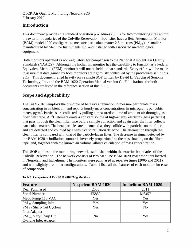
Introduction
This document provides the standard operation procedures (SOP) for two monitoring sites within
the exterior boundaries of the Colville Reservation. Both sites have a Beta Attenuation Monitor
(BAM) model 1020 configured to measure particulate matter 2.5 microns (PM2.5) or smaller,
manufactured by Met One Instruments Inc. and installed with associated meteorological
equipment.
Both monitors operated as non-regulatory for comparison to the National Ambient Air Quality
Standards (NAAQS). Although the Inchelium monitor has the capability to function as a Federal
Equivalent Method (FEM) monitor it will not be held to that standard. Every effort will be made
to assure that data gained by both monitors are rigorously controlled by the procedures set in this
SOP. This document relied heavily on a sample SOP written by David L. Vaughn of Sonoma
Technology, Inc. and the BAM 1020 Operation Manual version G. Full citations for both
documents are listed in the reference section of this SOP.
Scope and Applicability
The BAM-1020 employs the principle of beta ray attenuation to measure particulate mass
concentration in ambient air, and reports hourly mass concentrations in micrograms per cubic
meter, μg/m3. Particles are collected by pulling a measured volume of ambient air through glass
fiber filter tape. A 14
C element emits a constant source of high-energy electrons (beta particles)
that pass through the clean filter tape before sample collection and again after the filter collects
particulate matter. The beta particles are attenuated as they collide with particles on the filter,
and are detected and counted by a sensitive scintillation detector. The attenuation through the
clean filter is compared with that of the particle-laden filter. The decrease in signal detected by
the BAM 1020 scintillation counter is inversely proportional to the mass loading on the filter
tape, and, together with the known air volume, allows calculation of mass concentration.
This SOP applies to the monitoring network established within the exterior boundaries of the
Colville Reservation. The network consists of two Met One BAM 1020 PM2.5 monitors located
in Nespelem and Inchelium. The monitors were purchased at separate times (2005 and 2011)
and with slightly dissimilar configurations. Table 1 lists all the features of each monitor for ease
of comparison.
Table 1: Comparison of Two BAM 2010 PM2.5 Monitors
Feature Nespelem BAM 1020 Inchelium BAM 1020 Year Purchased 2005 2011
Serial Number E5889 M6457
Medo Pump 115 VAC Yes Yes
PM 10 Sampling Inlet Yes Yes
PM 2.5 Sharp Cut Cyclone
Inlet Adapter
Yes No
PM 2.5 Very Sharp Cut
Cyclone Inlet Adapter
No Yes
CTCR Air Quality Monitoring Network SOP
February 2012
2
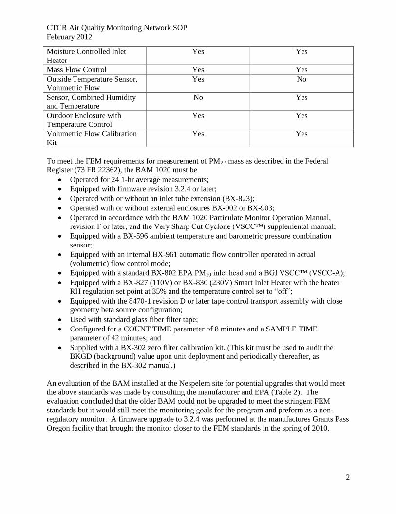
Moisture Controlled Inlet
Heater
Yes Yes
Mass Flow Control Yes Yes
Outside Temperature Sensor,
Volumetric Flow
Yes No
Sensor, Combined Humidity
and Temperature
No Yes
Outdoor Enclosure with
Temperature Control
Yes Yes
Volumetric Flow Calibration
Kit
Yes Yes
To meet the FEM requirements for measurement of PM2.5 mass as described in the Federal
Register (73 FR 22362), the BAM 1020 must be
Operated for 24 1-hr average measurements;
Equipped with firmware revision 3.2.4 or later;
Operated with or without an inlet tube extension (BX-823);
Operated with or without external enclosures BX-902 or BX-903;
Operated in accordance with the BAM 1020 Particulate Monitor Operation Manual,
revision F or later, and the Very Sharp Cut Cyclone (VSCC™) supplemental manual;
Equipped with a BX-596 ambient temperature and barometric pressure combination
sensor;
Equipped with an internal BX-961 automatic flow controller operated in actual
(volumetric) flow control mode;
Equipped with a standard BX-802 EPA PM10 inlet head and a BGI VSCC™ (VSCC-A);
Equipped with a BX-827 (110V) or BX-830 (230V) Smart Inlet Heater with the heater
RH regulation set point at 35% and the temperature control set to “off”;
Equipped with the 8470-1 revision D or later tape control transport assembly with close
geometry beta source configuration;
Used with standard glass fiber filter tape;
Configured for a COUNT TIME parameter of 8 minutes and a SAMPLE TIME
parameter of 42 minutes; and
Supplied with a BX-302 zero filter calibration kit. (This kit must be used to audit the
BKGD (background) value upon unit deployment and periodically thereafter, as
described in the BX-302 manual.)
An evaluation of the BAM installed at the Nespelem site for potential upgrades that would meet
the above standards was made by consulting the manufacturer and EPA (Table 2). The
evaluation concluded that the older BAM could not be upgraded to meet the stringent FEM
standards but it would still meet the monitoring goals for the program and preform as a non-
regulatory monitor. A firmware upgrade to 3.2.4 was performed at the manufactures Grants Pass
Oregon facility that brought the monitor closer to the FEM standards in the spring of 2010.
CTCR Air Quality Monitoring Network SOP
February 2012
3
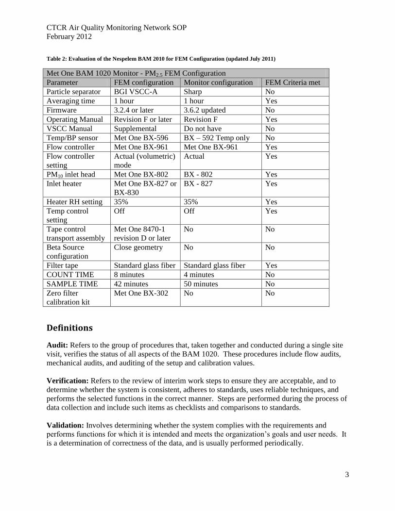
Table 2: Evaluation of the Nespelem BAM 2010 for FEM Configuration (updated July 2011)
Met One BAM 1020 Monitor - PM2.5 FEM Configuration
Parameter FEM configuration Monitor configuration FEM Criteria met
Particle separator BGI VSCC-A Sharp No
Averaging time 1 hour 1 hour Yes
Firmware 3.2.4 or later 3.6.2 updated No
Operating Manual Revision F or later Revision F Yes
VSCC Manual Supplemental Do not have No
Temp/BP sensor Met One BX-596 BX – 592 Temp only No
Flow controller Met One BX-961 Met One BX-961 Yes
Flow controller
setting
Actual (volumetric)
mode
Actual Yes
PM10 inlet head Met One BX-802 BX - 802 Yes
Inlet heater Met One BX-827 or
BX-830
BX - 827 Yes
Heater RH setting 35% 35% Yes
Temp control
setting
Off Off Yes
Tape control
transport assembly
Met One 8470-1
revision D or later
No No
Beta Source
configuration
Close geometry No No
Filter tape Standard glass fiber Standard glass fiber Yes
COUNT TIME 8 minutes 4 minutes No
SAMPLE TIME 42 minutes 50 minutes No
Zero filter
calibration kit
Met One BX-302 No No
Definitions
Audit: Refers to the group of procedures that, taken together and conducted during a single site
visit, verifies the status of all aspects of the BAM 1020. These procedures include flow audits,
mechanical audits, and auditing of the setup and calibration values.
Verification: Refers to the review of interim work steps to ensure they are acceptable, and to
determine whether the system is consistent, adheres to standards, uses reliable techniques, and
performs the selected functions in the correct manner. Steps are performed during the process of
data collection and include such items as checklists and comparisons to standards.
Validation: Involves determining whether the system complies with the requirements and
performs functions for which it is intended and meets the organization’s goals and user needs. It
is a determination of correctness of the data, and is usually performed periodically.

CTCR Air Quality Monitoring Network SOP
February 2012
4
Quality Control: Refers to the operational techniques and activities used to fulfill the requirements
for quality. This includes conducting maintenance and verification procedures in the field on the
BAM 1020.
Quality Assurance: Refers to the planned or systematic activities used to provide confidence that
the requirements for quality are fulfilled. Independent audits are a quality assurance activity.
Calibration: Refers to the act of adjusting an instrument after comparison with a standard.
Calibration Check: Refers only to checking an instrument against a standard and involves no
adjustment of the instrument.
Health and Safety Warnings
Safety precautions should be heeded during the setup and operation of the BAM 1020. Standard
safety rules regarding electricity and power tools should be observed at all time. The BAM 1020
contains a radioactive component which is explained by this direct quote from the Met One
BAM Operations Manual (Rev G).
“The Met One Instruments BAM-1020 contains a small 14
C (Carbon 14) beta radiation-emitting
source. The activity of the source is 60 μCi ±15μCi (microcurie), which is below the “Exempt
Concentration Limit” as defined in 10 CFR Section 30.70–Schedule A. The owner of a BAM-
1020 is not required to obtain any license in the United States to own or operate the unit. The
owner of a BAM-1020 may elect to return the entire unit to Met One Instruments for recycling of
the 14
C source when the unit has reached the end of its service life, although the owner is under
no obligation to do so. Under no circumstances should anyone but factory technicians attempt to
remove or access the beta source. The beta source has a half-life of about 5730 years, and should
never need to be replaced. Neither the 14
C source nor the beta particle detectors are serviceable in
the field. Should these components require repair or replacement; the BAM-1020 must be
returned to the factory for service and recalibration.”
Installation of the 10 meter meteorological tower requires several precautions. Follow
manufactures installation procedures for initial setup and reverse these if dissembling occurs.
The tower should be placed 2 times the height at a minimum away from hazards such as electric
lines. Plan the process before beginning and coordinate with all involved. Do not use metal
ladders, work on wet or windy days but wear rubber soled shoes and other personal protective
equipment. The complete manufactures safety and installation instructions are on file in the Air
quality Program office.
The monitor enclosure and chassis ground on the BAM 1020 should be connected with a suitable
ground point such as a rod.
CTCR Air Quality Monitoring Network SOP
February 2012
5
Personnel Qualifications
The quality assurance (QA) procedures detailed in this SOP require an understanding of the
BAM 1020 flow system, calibration protocol and normal operating processes. EPA Guidance
for Quality Assurance Project Plans (U.S. Environmental Protection Agency, 2002)
recommends that all field operations personnel should be familiar with environmental field
measurement techniques including:
• Operation of the PM2.5 sampler;
• Calibrate, audit, and troubleshoot the PM2.5 sampler; and
• Use common methods to determine temperature, pressure, and flow rate.
Several training opportunities exist for the operation of the BAM 1020 that new and current
personnel could benefit from. Met One offers a free in house class at their Grants Pass facility
that covers installation, operation, maintenance and troubleshooting. The Institute for Tribal
Environmental Professionals (ITEP) offers a similar three day class sporadically depending on
requests.
CTCR Air Quality Monitoring Network SOP
February 2012
6
Installation Procedures
The tasks associated with installation include unpacking and inspection of the BAM 1020
components, acceptance testing, site selection to meet 40 CFR Part 58 siting requirements,
enclosure selection, installing the BAM 1020 main unit and supporting peripheral hardware, and
instrument configuration procedures. Many of the items in the previous list also apply to moving
and setting up of the BAM 1020 purchased in 2005.
Unpacking, Inspection and Moving
A physical inspection of the BAM 1020 system should be made upon receipt from Met One.
Visible damage to the shipping container needs to be reported to the carrier and a claim filed
immediately. Notify Met One after informing the commercial carrier of any problems. System
components should be verified against the packing list and any missing or damaged components
reported immediately to Met One. The BAM 1020 is shipped with two white foam rings and a
white plastic shim inside the front of the unit, which prevent the moving parts of the tape control
assembly from being damaged in transit. Do not remove the foam rings until the BAM 1020 is
ready to be installed. These rings must be in place on the transport assembly anytime the unit is
being moved in order to avoid damaging the tape control mechanism. The special box and foam
packing material that the BAM 1020 is shipped in should be stored, in the event the unit must be
returned to the factory.
Acceptance Testing
After the components have been verified against the packing list, the system should be
assembled on a bench and an acceptance test performed. Utilize the instructions and tools in the
BAM 1020 service tool kit (BX-308) to confirm all components in the BAM 1020 are correctly
aligned and functioning properly. A copy of the instruction for the tool kit can be found in
Appendix H. Components checked will be: Tape Reel Adjustment; Dark Count Test and Nozzle
Spacing. Follow the instruction under BAM Installation for installing individual components
for the bench test.
A zero test will be part of the bench test procedure to verify that the unit is working properly
before being transported to the monitoring site. A 72-hr zero filter, or background, at the time of
field installation will also be conducted to meet the requirements of FEM EQPM-0308-170. It is
important that this test take place at the field site to account for site-specific background noise.
A list of suggested acceptance testing protocols for the BAM 1020 with a reference to the
applicable sections of the SOP and the Operation Manual (Rev G.) are shown in Table 3.
Acceptance testing should be performed on any monitoring equipment that are relocated and/or
stored for extended periods.

CTCR Air Quality Monitoring Network SOP
February 2012
7
Table 3: Acceptance testing procedures for the BAM 1020
Test Location Comments SOP Section
BAM 1020
Operation
Manual
Section1
Power on and Warm up Bench
Verify that the BX-
596 temperature and
pressure readings are
realistic and
auxiliary sensor
signals are
functioning
Power On and Warm Up; Page 15
Power On; 3.1
Page 19
Verify Settings Bench
Confirm all setting
are correct
Verify BAM
1020 Setting;
Page 29
Setup Menu; 6
Page 39
Self-test Bench
Load tape and run
self-test
Perform
Self-Test; Page
17
Self-Test; 3.5
Page 22
Flow
Verification/Calibration Bench
Follow instruction
below
Flow,
Temperature
and Pressure
Calibration
Page 28
Field
Calibration of
Flow System –
Actual; 5.6
Page 35
Leak check Bench
Should be < 1.0 lpm Leak Check;
Page 23
Leak Check
Procedure; 5.3
Page 32
Filter-T and RH Test Bench
+/- 1 deg C; RH
reasonable
Test the Filter
Temperature
and RH sensors
Page 30
Filter-T Test;
7.18 Page 62
Service Tool Kit Bench Follow instructions
for BX-308 tool kit Appendix H
Instructions
with tool kit
Zero test Bench
and Field
Follow instruction
with BX-302 zero
filter calibration kit
72 Hour Field
BKGD Zero
Test; Page 19
Zero
Background
Tests; 7.7 Page
57
1Pages shown are for operation manual revision G; pages for revision H are different but the sections are the same.
CTCR Air Quality Monitoring Network SOP
February 2012
8
Site Selection
Site selection ensures uniform collection of compatible and comparable data by meeting standard
criteria. The criteria shown in Table 4 are based on 40 CFR Part 58, App E applicable to
ambient monitoring of PM 2.5 and 40 CFR Part 58, App D, and Section 4.7 general monitoring
requirements. Additional information can be found in the BAM 1020 operation manual, section
2.3.
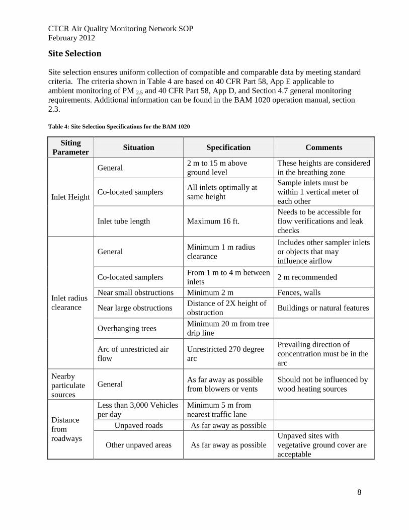
Table 4: Site Selection Specifications for the BAM 1020
Siting
Parameter Situation Specification Comments
Inlet Height
General 2 m to 15 m above
ground level
These heights are considered
in the breathing zone
Co-located samplers All inlets optimally at
same height
Sample inlets must be
within 1 vertical meter of
each other
Inlet tube length Maximum 16 ft.
Needs to be accessible for
flow verifications and leak
checks
Inlet radius
clearance
General Minimum 1 m radius
clearance
Includes other sampler inlets
or objects that may
influence airflow
Co-located samplers From 1 m to 4 m between
inlets 2 m recommended
Near small obstructions Minimum 2 m Fences, walls
Near large obstructions Distance of 2X height of
obstruction Buildings or natural features
Overhanging trees Minimum 20 m from tree
drip line
Arc of unrestricted air
flow
Unrestricted 270 degree
arc
Prevailing direction of
concentration must be in the
arc
Nearby
particulate
sources
General As far away as possible
from blowers or vents
Should not be influenced by
wood heating sources
Distance
from
roadways
Less than 3,000 Vehicles
per day
Minimum 5 m from
nearest traffic lane
Unpaved roads As far away as possible
Other unpaved areas As far away as possible
Unpaved sites with
vegetative ground cover are
acceptable
CTCR Air Quality Monitoring Network SOP
February 2012
9
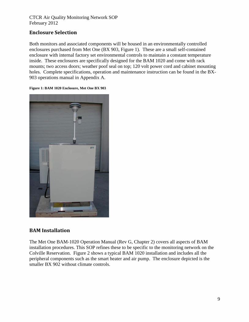
Enclosure Selection
Both monitors and associated components will be housed in an environmentally controlled
enclosures purchased from Met One (BX 903, Figure 1). These are a small self-contained
enclosure with internal factory set environmental controls to maintain a constant temperature
inside. These enclosures are specifically designed for the BAM 1020 and come with rack
mounts; two access doors; weather poof seal on top; 120 volt power cord and cabinet mounting
holes. Complete specifications, operation and maintenance instruction can be found in the BX-
903 operations manual in Appendix A.
Figure 1: BAM 1020 Enclosure, Met One BX 903
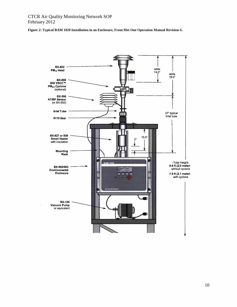
BAM Installation
The Met One BAM-1020 Operation Manual (Rev G, Chapter 2) covers all aspects of BAM
installation procedures. This SOP refines these to be specific to the monitoring network on the
Colville Reservation. Figure 2 shows a typical BAM 1020 installation and includes all the
peripheral components such as the smart heater and air pump. The enclosure depicted is the
smaller BX 902 without climate controls.
CTCR Air Quality Monitoring Network SOP
February 2012
10
Figure 2: Typical BAM 1020 Installation in an Enclosure, From Met One Operation Manual Revision G
CTCR Air Quality Monitoring Network SOP
February 2012
11
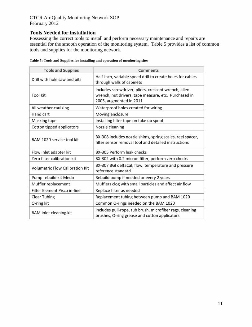
Tools Needed for Installation Possessing the correct tools to install and perform necessary maintenance and repairs are
essential for the smooth operation of the monitoring system. Table 5 provides a list of common
tools and supplies for the monitoring network.
Table 5: Tools and Supplies for installing and operation of monitoring sites
Tools and Supplies Comments
Drill with hole saw and bits Half-inch, variable speed drill to create holes for cables through walls of cabinets
Tool Kit Includes screwdriver, pliers, crescent wrench, allen wrench, nut drivers, tape measure, etc. Purchased in 2005, augmented in 2011
All weather caulking Waterproof holes created for wiring
Hand cart Moving enclosure
Masking tape Installing filter tape on take up spool
Cotton tipped applicators Nozzle cleaning
BAM 1020 service tool kit BX-308 includes nozzle shims, spring scales, reel spacer, filter sensor removal tool and detailed instructions
Flow inlet adapter kit BX-305 Perform leak checks
Zero filter calibration kit BX-302 with 0.2 micron filter, perform zero checks
Volumetric Flow Calibration Kit BX-307 BGI deltaCal, flow, temperature and pressure reference standard
Pump rebuild kit Medo Rebuild pump if needed or every 2 years
Muffler replacement Mufflers clog with small particles and affect air flow
Filter Element Pisco in-line Replace filter as needed
Clear Tubing Replacement tubing between pump and BAM 1020
O-ring kit Common O-rings needed on the BAM 1020
BAM inlet cleaning kit Includes pull-rope, tub brush, microfiber rags, cleaning brushes, O-ring grease and cotton applicators

CTCR Air Quality Monitoring Network SOP
February 2012
12
Install BAM 1020 in Enclosure The BX 903 enclosure is specifically designed for the BAM 1020 and includes the top sample
pipe flange, shelf and rack mounts for the precise placement of the instrument. Place the BAM
1020 on the self and fasten to the rack brackets with the screws provided. This configuration
provides the steadiest position and the most access room. With this configuration the inlet pipe
should align properly with the inlet receiver on the BAM 1020. The enclosure should be
positioned so that during operations and maintenance the door will provide a shield from the
prevailing wind. This is particularly important during precipitation events to minimize moisture
entering the enclosure.
Insert Inlet Pipe and Install Smart Heater Remove the white cap and rubber seal from the flange assembly and set aside. Lower the inlet
tube through the flange assembly in the roof and into the inlet receiver on the BAM 1020. Make
sure the inlet tube is fully seated. Check that the inlet tube rotates freely. If it does not, there may
be an inlet alignment problem that needs to be corrected before proceeding.
Temporarily lift the inlet tube out of the BAM 1020 and slide the Smart Heater onto the inlet
tube, with the heater cable positioned toward the bottom. Reinsert the inlet tube into the BAM
1020 and check that it is fully seated. Position the Smart Heater 2 inches above the BAM 1020
inlet receiver and tighten the two set screws that attach the heater to the inlet tube. Wrap the
supplied 12 inch cylindrical insulation around the heater body, and peel back the adhesive cover
strip to secure it in place or tape closed.
Wet the inlet pipe rubber seal with water or alcohol and slide it down the pipe until it sits inside
the gray plastic fitting that was previously screwed into the roof flange. This grommet is tight
fitting, and wetting it will help slide it along the pipe. Be careful not to apply too much water or
alcohol to avoid trickling down the tube into the inlet receiver on the top of the BAM-1020.
When the grommet is in place, slide the white cap down the inlet and hand tighten it to the gray
plastic fitting.
To prevent the buildup of a static charge on the inlet tube a solid station ground must be
established with the BAM 1010 chassis. Tightening the two ¼-20 set screws located in the inlet
receiver of the BAM creates a ground connection between the tube and the chassis, this action
also secures the tube in place. To check if a competent ground has been established scrape a
small spot on the clear anodizing near the bottom of the inlet tube and measure the resistance
between the spot and the chassis ground terminal on the back of the BAM 1020. The resistance
should a few ohms or less.
Install Ambient Temperature and Barometric Pressure Sensors The BX-596 Ambient Temperature (AT) and Barometric Pressure sensor (BP) combination
sensor attaches directly to the inlet tube with a supplied U-bolt. The combination BX-596 is
installed at the Inchelium site. The BX-592 ambient temperature sensor is attached to the inlet
tube using the cross arm assembly at the Nespelem site. Input from these sensors provides
correction values as part of the volumetric flow calculations.

CTCR Air Quality Monitoring Network SOP
February 2012
13
Install the PM 2.5 and PM 10 Inlet Separator Heads A BGI Sharp Cut Cyclone will be installed on top of the inlet tube beneath the standard PM 10
inlet head on the Nespelem monitor. The Inchelium monitor will have a BGI Very Sharp Cut
Cyclone (VSCC) installed on the inlet tube under the PM 10 inlet head. See Appendix K for
VSCC instruction and maintenance information.
Wiring and Plumbing
Wiring connections include power availability to the outdoor enclosure, chassis ground wire,
power distribution within the cabinet, use of an uninterruptable power supply (UPS), smart
heater installation, and connection of the BAM 1020 and air pump.
Power to the Monitoring Sites The Nespelem and Inchelium sites will have electricity provided from a metered connection to
an outdoor quality breaker box and outlet. The enclosure will be plugged into the three prong
outlet to run the heater/air conditioner, and the monitoring equipment. The site plans provided in
Appendix B details the location of the meter, underground wires, breaker box, outlet and
enclosure.
Power Connection to the BAM 1020 and Pump A power strip wired into the enclosure junction box on the inside of the cabinet provides electric
availability to all equipment installed. The power strip includes an on/off switch that controls the
components plugged into it. An uninterruptable power source (UPS) with voltage modulation
plugs into the strip and then provides power to the BAM 1020 and air pump. See the Compu-
cessory model 25650 user manual in Appendix J for basic operation and troubleshooting options
Auxiliary Ground A ground connection between the chassis ground terminal on the rear terminal strip of the BAM
1020 and the grounding rod will be established by utilizing the green/yellow wire provided with
each monitor. Additional the enclosure will be grounded to the same rod.
Connect the Pump Tubing and Control Signal Cables The Medo pumps will be placed under the shelf on the floor of the cabinet. The air tubing (clear
10mm O.D., 6.5mm I.D. Polyurethane) connects to the BAM with a compression fitting and then
to the air pump. Connect the two-wire signal cable supplied with the pump to the terminals on
the back of the BAM marked “Pump Control”. The polarity of the wires does not matter, but the
end of the cable with the square black ferrite filter goes toward the BAM 1020. Connect the other
end of the cable to the two terminals of the pump control box mounted on the pump.
Pump Muffler The muffler on the Medo air pumps will eventually clog and cause a decrease of air flow through
the system. This will cause a loss of data and eventually will harm the pump. The muffler
should be replaced every 6 months or sooner if particulate matter concentrations are high.
Alternately a length of tubing 3 foot long can be used to muffle the pump noise and be vented to
the outside of the enclosure. A weather proof and bug resistant seal should be used if an outside
vent is installed.
CTCR Air Quality Monitoring Network SOP
February 2012
14
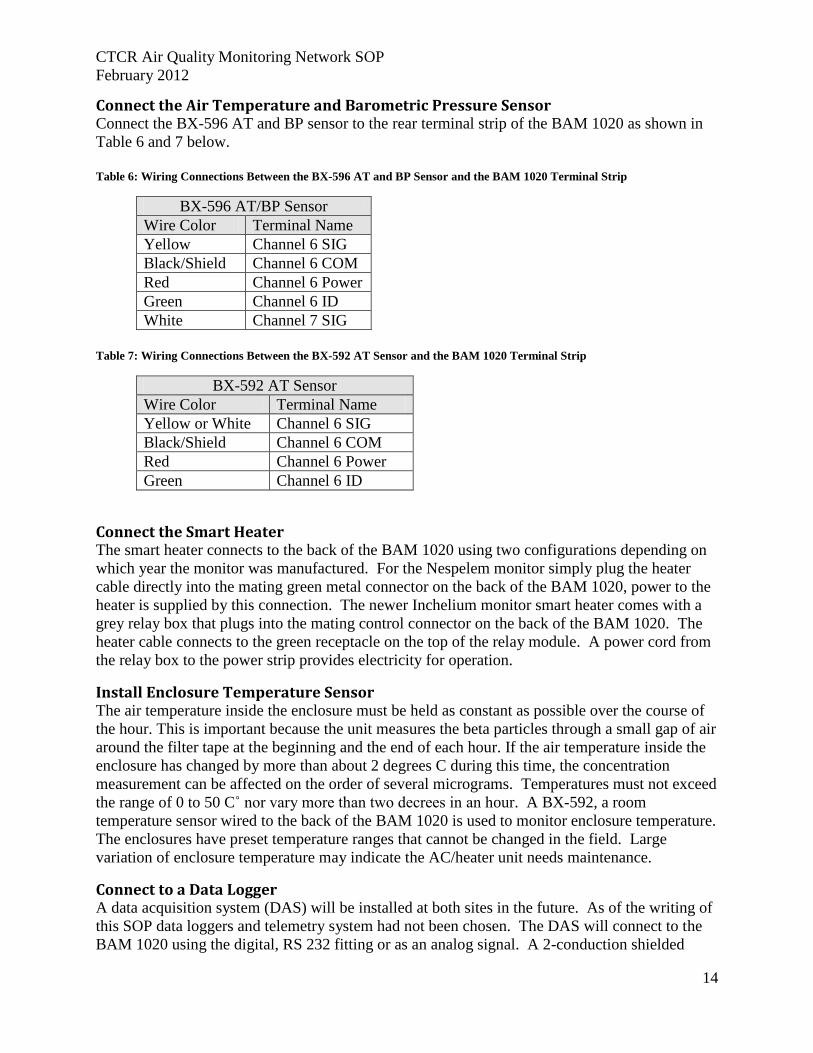
Connect the Air Temperature and Barometric Pressure Sensor Connect the BX-596 AT and BP sensor to the rear terminal strip of the BAM 1020 as shown in
Table 6 and 7 below.
Table 6: Wiring Connections Between the BX-596 AT and BP Sensor and the BAM 1020 Terminal Strip
BX-596 AT/BP Sensor
Wire Color Terminal Name
Yellow Channel 6 SIG
Black/Shield Channel 6 COM
Red Channel 6 Power
Green Channel 6 ID
White Channel 7 SIG
Table 7: Wiring Connections Between the BX-592 AT Sensor and the BAM 1020 Terminal Strip
BX-592 AT Sensor
Wire Color Terminal Name
Yellow or White Channel 6 SIG
Black/Shield Channel 6 COM
Red Channel 6 Power
Green Channel 6 ID
Connect the Smart Heater The smart heater connects to the back of the BAM 1020 using two configurations depending on
which year the monitor was manufactured. For the Nespelem monitor simply plug the heater
cable directly into the mating green metal connector on the back of the BAM 1020, power to the
heater is supplied by this connection. The newer Inchelium monitor smart heater comes with a
grey relay box that plugs into the mating control connector on the back of the BAM 1020. The
heater cable connects to the green receptacle on the top of the relay module. A power cord from
the relay box to the power strip provides electricity for operation.
Install Enclosure Temperature Sensor The air temperature inside the enclosure must be held as constant as possible over the course of
the hour. This is important because the unit measures the beta particles through a small gap of air
around the filter tape at the beginning and the end of each hour. If the air temperature inside the
enclosure has changed by more than about 2 degrees C during this time, the concentration
measurement can be affected on the order of several micrograms. Temperatures must not exceed
the range of 0 to 50 C˚ nor vary more than two decrees in an hour. A BX-592, a room
temperature sensor wired to the back of the BAM 1020 is used to monitor enclosure temperature.
The enclosures have preset temperature ranges that cannot be changed in the field. Large
variation of enclosure temperature may indicate the AC/heater unit needs maintenance.
Connect to a Data Logger A data acquisition system (DAS) will be installed at both sites in the future. As of the writing of
this SOP data loggers and telemetry system had not been chosen. The DAS will connect to the
BAM 1020 using the digital, RS 232 fitting or as an analog signal. A 2-conduction shielded
CTCR Air Quality Monitoring Network SOP
February 2012
15
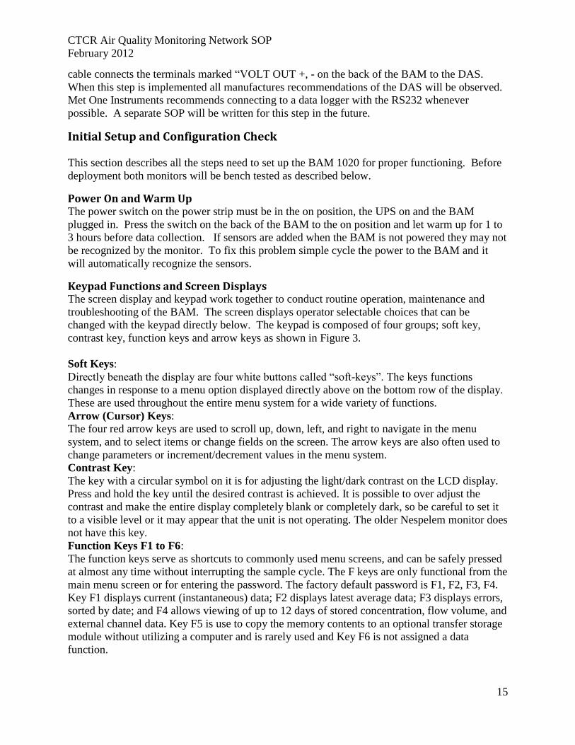
cable connects the terminals marked “VOLT OUT +, - on the back of the BAM to the DAS.
When this step is implemented all manufactures recommendations of the DAS will be observed.
Met One Instruments recommends connecting to a data logger with the RS232 whenever
possible. A separate SOP will be written for this step in the future.
Initial Setup and Configuration Check
This section describes all the steps need to set up the BAM 1020 for proper functioning. Before
deployment both monitors will be bench tested as described below.
Power On and Warm Up The power switch on the power strip must be in the on position, the UPS on and the BAM
plugged in. Press the switch on the back of the BAM to the on position and let warm up for 1 to
3 hours before data collection. If sensors are added when the BAM is not powered they may not
be recognized by the monitor. To fix this problem simple cycle the power to the BAM and it
will automatically recognize the sensors.
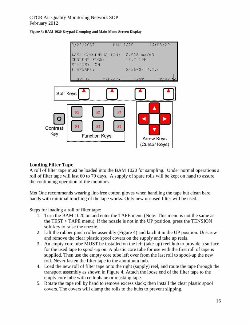
Keypad Functions and Screen Displays The screen display and keypad work together to conduct routine operation, maintenance and
troubleshooting of the BAM. The screen displays operator selectable choices that can be
changed with the keypad directly below. The keypad is composed of four groups; soft key,
contrast key, function keys and arrow keys as shown in Figure 3.
Soft Keys:
Directly beneath the display are four white buttons called “soft-keys”. The keys functions
changes in response to a menu option displayed directly above on the bottom row of the display.
These are used throughout the entire menu system for a wide variety of functions.
Arrow (Cursor) Keys:
The four red arrow keys are used to scroll up, down, left, and right to navigate in the menu
system, and to select items or change fields on the screen. The arrow keys are also often used to
change parameters or increment/decrement values in the menu system.
Contrast Key:
The key with a circular symbol on it is for adjusting the light/dark contrast on the LCD display.
Press and hold the key until the desired contrast is achieved. It is possible to over adjust the
contrast and make the entire display completely blank or completely dark, so be careful to set it
to a visible level or it may appear that the unit is not operating. The older Nespelem monitor does
not have this key.
Function Keys F1 to F6:
The function keys serve as shortcuts to commonly used menu screens, and can be safely pressed
at almost any time without interrupting the sample cycle. The F keys are only functional from the
main menu screen or for entering the password. The factory default password is F1, F2, F3, F4.
Key F1 displays current (instantaneous) data; F2 displays latest average data; F3 displays errors,
sorted by date; and F4 allows viewing of up to 12 days of stored concentration, flow volume, and
external channel data. Key F5 is use to copy the memory contents to an optional transfer storage
module without utilizing a computer and is rarely used and Key F6 is not assigned a data
function.
CTCR Air Quality Monitoring Network SOP
February 2012
16
Figure 3: BAM 1020 Keypad Grouping and Main Menu Screen Display
Loading Filter Tape A roll of filter tape must be loaded into the BAM 1020 for sampling. Under normal operations a
roll of filter tape will last 60 to 70 days. A supply of spare rolls will be kept on hand to assure
the continuing operation of the monitors.
Met One recommends wearing lint-free cotton gloves when handling the tape but clean bare
hands with minimal touching of the tape works. Only new un-used filter will be used.
Steps for loading a roll of filter tape:
1. Turn the BAM 1020 on and enter the TAPE menu (Note: This menu is not the same as
the TEST > TAPE menu). If the nozzle is not in the UP position, press the TENSION
soft-key to raise the nozzle.
2. Lift the rubber pinch roller assembly (Figure 4) and latch it in the UP position. Unscrew
and remove the clear plastic spool covers on the supply and take up reels.
3. An empty core tube MUST be installed on the left (take-up) reel hub to provide a surface
for the used tape to spool-up on. A plastic core tube for use with the first roll of tape is
supplied. Then use the empty core tube left over from the last roll to spool-up the new
roll. Never fasten the filter tape to the aluminum hub.
4. Load the new roll of filter tape onto the right (supply) reel, and route the tape through the
transport assembly as shown in Figure 4. Attach the loose end of the filter tape to the
empty core tube with cellophane or masking tape.
5. Rotate the tape roll by hand to remove excess slack; then install the clear plastic spool
covers. The covers will clamp the rolls to the hubs to prevent slipping.
CTCR Air Quality Monitoring Network SOP
February 2012
17
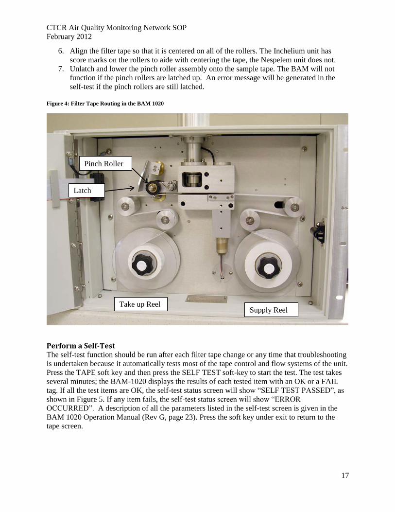
6. Align the filter tape so that it is centered on all of the rollers. The Inchelium unit has
score marks on the rollers to aide with centering the tape, the Nespelem unit does not.
7. Unlatch and lower the pinch roller assembly onto the sample tape. The BAM will not
function if the pinch rollers are latched up. An error message will be generated in the
self-test if the pinch rollers are still latched.
Figure 4: Filter Tape Routing in the BAM 1020
Perform a Self-Test The self-test function should be run after each filter tape change or any time that troubleshooting
is undertaken because it automatically tests most of the tape control and flow systems of the unit.
Press the TAPE soft key and then press the SELF TEST soft-key to start the test. The test takes
several minutes; the BAM-1020 displays the results of each tested item with an OK or a FAIL
tag. If all the test items are OK, the self-test status screen will show “SELF TEST PASSED”, as
shown in Figure 5. If any item fails, the self-test status screen will show “ERROR
OCCURRED”. A description of all the parameters listed in the self-test screen is given in the
BAM 1020 Operation Manual (Rev G, page 23). Press the soft key under exit to return to the
tape screen.
Pinch Roller
Latch
Take up Reel Supply Reel

CTCR Air Quality Monitoring Network SOP
February 2012
18
Figure 5: The self-test status screen following a test with no errors.
Set the BAM Clock Press the SETUP Soft Key on the main screen to access the clock setting. Use the Arrow Keys to
move to the desired menu item and press the SELECT Soft Key to display the information.
BAM 1020 time is a 24-hr clock only. Use the arrow keys to select and increase/decrease the
desired field, then press the SAVE soft-key. The BAM1020 clock may drift as much as a minute
or two per month and should be checked monthly to ensure correct sample timing. The BAM
clock should be permanently set for Pacific Standard Time and should never be reset to Daylight
Savings Time.
System Configuration Parameters Three screens must be viewed to verify that the BAM 1020 is properly configured: the SAMPLE
screen, the CALIBRATE screen, and the HEATER screen. Detailed descriptions of other
SETUP menu screens are given in the BAM 1020 Operation Manual (Rev G, pages 39-51). Table 8: Sample Screen Setting for the Nespelem and Inchelium BAM 1020
Sample Setup Setting Nespelem Monitor Inchelium Monitor
RS232 9600 baud 9600 baud
BAM Sample 50 minutes 42 minutes
Station Number 2 3
Met Sample 60 minutes 60 minutes
Range 1.00 mg 1.00 mg
Offset -0.015 -0.015
Concentration Units μmg/m3 μmg/m3
Count Time 4 minutes 8 minutes
Each BAM 1020 is calibrated at the factory and has unique settings that are provided on an
accompanying calibration certificate. A copy of this certificate, specific to the instrument’s serial
number, will be kept at each site and on file in the air quality program office. The SETUP >
CALIBRATE screen stores most of the factory-determined calibration parameters for the BAM
1020. These settings will never be changed without specific instructions from Met One under
most circumstances. The setting will be periodically reviewed during verifications and audits.
CTCR Air Quality Monitoring Network SOP
February 2012
19
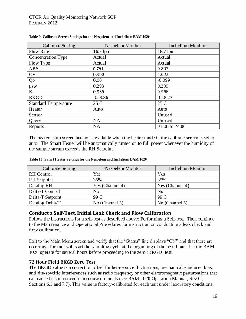
Table 9: Calibrate Screen Settings for the Nespelem and Inchelium BAM 1020
Calibrate Setting Nespelem Monitor Inchelium Monitor
Flow Rate 16.7 lpm 16.7 lpm
Concentration Type Actual Actual
Flow Type Actual Actual
ABS 0.791 0.807
CV 0.990 1.022
Qo 0.00 -0.099
μsw 0.293 0.299
K 0.939 0.966
BKGD -0.0036 -0.0023
Standard Temperature 25 C 25 C
Heater Auto Auto
Sensor Unused
Query NA Unused
Reports NA 01:00 to 24:00
The heater setup screen becomes available when the heater mode in the calibrate screen is set to
auto. The Smart Heater will be automatically turned on to full power whenever the humidity of
the sample stream exceeds the RH Setpoint.
Table 10: Smart Heater Settings for the Nespelem and Inchelium BAM 1020
Calibrate Setting Nespelem Monitor Inchelium Monitor
RH Control Yes Yes
RH Setpoint 35% 35%
Datalog RH Yes (Channel 4) Yes (Channel 4)
Delta-T Control No No
Delta-T Setpoint 99 C 99 C
Detalog Delta-T No (Channel 5) No (Channel 5)
Conduct a Self-Test, Initial Leak Check and Flow Calibration Follow the instructions for a self-test as described above; Performing a Self-test. Then continue
to the Maintenance and Operational Procedures for instruction on conducting a leak check and
flow calibration.
Exit to the Main Menu screen and verify that the “Status” line displays “ON” and that there are
no errors. The unit will start the sampling cycle at the beginning of the next hour. Let the BAM
1020 operate for several hours before proceeding to the zero (BKGD) test.
72 Hour Field BKGD Zero Test The BKGD value is a correction offset for beta-source fluctuations, mechanically induced bias,
and site-specific interferences such as radio frequency or other electromagnetic perturbations that
can cause bias in concentration measurements (see BAM-1020 Operation Manual, Rev G,
Sections 6.3 and 7.7). This value is factory-calibrated for each unit under laboratory conditions,
CTCR Air Quality Monitoring Network SOP
February 2012
20
but BAM 1020 units set up to monitor PM2.5 under FEM EQPM-0308-170 must have this value
field verified (and adjusted if necessary) when deployed in its normal operating environment,
and periodically afterwards, using the BX-302 Zero Filter Calibration Kit. Met One provides a
separate manual which will be followed at both monitoring sites (Appendix E). The BAM 1020
does not provide a flag or otherwise mark the data recorded while conducting a zero test so write
down the start and finish times of the test.
After the bench and initial field installation 72 hour zero tests the monitors will be checked
periodically to verify the values are valid. This test will be conducted on an annual basis to
mimic the FEM guidance.
CTCR Air Quality Monitoring Network SOP
February 2012
21
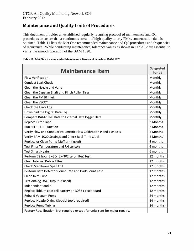
Maintenance and Quality Control Procedures This document provides an established regularly recurring protocol of maintenance and QC
procedures to ensure that a continuous stream of high quality hourly PM2.5 concentration data is
obtained. Table 11 lists the Met One recommended maintenance and QC procedures and frequencies
of recurrence. While conducting maintenance, tolerance values as shown in Table 12 are essential to
verify the smooth operation of the BAM 1020.
Table 11: Met One Recommended Maintenance Items and Schedule, BAM 1020
Maintenance Item Suggested
Period
Flow Verification Monthly
Conduct Leak Check Monthly
Clean the Nozzle and Vane Monthly
Clean the Capstan Shaft and Pinch Roller Tires Monthly
Clean the PM10 Inlet Monthly
Clean the VSCC™ Monthly
Check the Error Log Monthly
Download the Digital Data Log Monthly
Compare BAM-1020 Data to External Data logger Data Monthly
Replace Filter Tape 2 Months
Run SELF-TEST Function 2 Months
Verify Flow and Conduct Volumetric Flow Calibration P and T checks 2 Months
Verify BAM-1020 Settings and Check Real-Time Clock 2 Months
Replace or Clean Pump Muffler (if used) 6 months
Test Filter Temperature and RH sensors 6 months
Test Smart Heater 6 months
Perform 72 hour BKGD (BX-302 zero filter) test 12 months
Clean Internal Debris Filter 12 months
Check Membrane Span Foil 12 months
Perform Beta Detector Count Rate and Dark Count Test 12 months
Clean Inlet Tube 12 months
Test Analog DAC Output (if used) 12 months
Independent audit 12 months
Replace lithium coin cell battery on 3032 circuit board 12 months
Rebuild Vacuum Pump 24 months
Replace Nozzle O-ring (Special tools required) 24 months
Replace Pump Tubing 24 months
Factory Recalibration. Not required except for units sent for major repairs.
CTCR Air Quality Monitoring Network SOP
February 2012
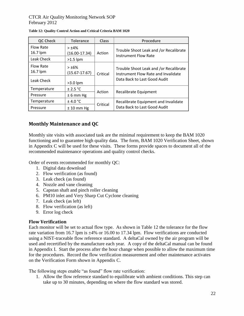
22
Table 12: Quality Control Action and Critical Criteria BAM 1020
QC Check Tolerance Class Procedure
Flow Rate 16.7 lpm
> ±4% (16.00-17.34) Action
Trouble Shoot Leak and /or Recalibrate Instrument Flow Rate
Leak Check >1.5 lpm
Flow Rate 16.7 lpm
> ±6% (15.67-17.67) Critical
Trouble Shoot Leak and /or Recalibrate Instrument Flow Rate and Invalidate Data Back to Last Good Audit Leak Check
>3.0 lpm
Temperature ± 2.5 °C Action Recalibrate Equipment
Pressure ± 6 mm Hg
Temperature ± 4.0 °C Critical
Recalibrate Equipment and Invalidate Data Back to Last Good Audit Pressure ± 10 mm Hg
Monthly Maintenance and QC
Monthly site visits with associated task are the minimal requirement to keep the BAM 1020
functioning and to guarantee high quality data. The form, BAM 1020 Verification Sheet, shown
in Appendix C will be used for these visits. These forms provide spaces to document all of the
recommended maintenance operations and quality control checks.
Order of events recommended for monthly QC:
1. Digital data download
2. Flow verification (as found)
3. Leak check (as found)
4. Nozzle and vane cleaning
5. Capstan shaft and pinch roller cleaning
6. PM10 inlet and Very Sharp Cut Cyclone cleaning
7. Leak check (as left)
8. Flow verification (as left)
9. Error log check
Flow Verification Each monitor will be set to actual flow type. As shown in Table 12 the tolerance for the flow
rate variation from 16.7 lpm is ±4% or 16.00 to 17.34 lpm. Flow verifications are conducted
using a NIST-traceable flow reference standard. A deltaCal owned by the air program will be
used and recertified by the manufacture each year. A copy of the deltaCal manual can be found
in Appendix I. Start the process after the hour change when possible to allow the maximum time
for the procedures. Record the flow verification measurement and other maintenance activates
on the Verification Form shown in Appendix C.
The following steps enable “as found” flow rate verification:
1. Allow the flow reference standard to equilibrate with ambient conditions. This step can
take up to 30 minutes, depending on where the flow standard was stored.
CTCR Air Quality Monitoring Network SOP
February 2012
23
2. From the Main menu, press the TEST Soft Key, which will stop the sample cycle.
3. Select the TEST > FLOW menu to access the MULTIPOINT FLOW CALIBRATE
screen; the password will be required.
4. Remove the sampling inlet head.
5. Press the NEXT Soft Key until “FLOW 3” is highlighted. The pump will be running and
the flow controller will be regulating the flow to 16.7 lpm volumetric.
6. Attach the reference flow standard to the inlet tube and allow the reading to stabilize.
7. Record the “Actual Flow” volumetric flow rate from the flow reference standard.
8. Record the “BAM Indicated Flow” rate from the BAM column for FLOW 3.
9. If the “as found” flow reference standard reading is more than 4% different from 16.7
lpm (±0.67 lpm, or outside the range 16.0 to 17.34 lpm), a flow calibration should be
performed.
10. Record the actual flow and BAM indicated flow for the 15.0 and 18.3 lpm screens.
These will be utilized when calculating QA values for bias and precision.
11. Continue with other maintenance and QC procedures and mark the results on the
verification sheet. When complete, replace the sampling inlet head, and place the BAM
into OPERATE mode.
Leak Check The “as found” leak check should be performed after the “as found” flow verification.
From the Main menu, press the TEST Soft Key and stop the sample cycle if running.
Remove the sampler head from the inlet tube. Install a BX-305 or BX-302 leak test valve onto
the inlet tube and turn the valve to the OFF position to prevent any air from entering.
In the TEST > TAPE menu, advance the tape to a fresh, unused spot. In the TEST > PUMP
menu, turn on the pump. The flow rate should drop below 1.0 lpm. Write the flow rate under as
found on the verification sheet. If the leak flow value is 1.0 lpm or greater, the nozzle and vane
need cleaning, or there may be another small leak in the system. Resolve the leak and perform
the check again. A properly functioning BAM with a clean nozzle and vane will usually have a
leak value of about 0.5 lpm or less using this method. Turn the pump off, remove the leak test
valve, and re-install the inlet heads.
As found leak checks show if a problem developed subsequent to the last maintenance check.
Use the guidance shown in Table 12 to determine data viability. Generally leak checks should
result in a flow of under 0.5 lpm if all is functioning well. With the buildup of debris around the
nozzle/tape interface flows may increase up to 1 lpm, which indicates a cleaning is necessary.
Values greater than 1 lmp may indicate additional air leak problems. In all cases of higher than
expected leak values clean the nozzle and vane using the process described below.
Clean the Nozzle and Vane The nozzle and vane (located under the nozzle) must be cleaned regularly to prevent leaks and
measurement errors. The cleaning must be done at least each time the filter tape is changed,
though monthly cleaning is highly recommended. Use the following steps to clean the parts.
Refer to the photos below.
1. Raise the nozzle in the TEST > PUMP menu. Remove the filter tape (if installed) from the
nozzle area. It is not necessary to completely remove the tape from the unit.
CTCR Air Quality Monitoring Network SOP
February 2012
24
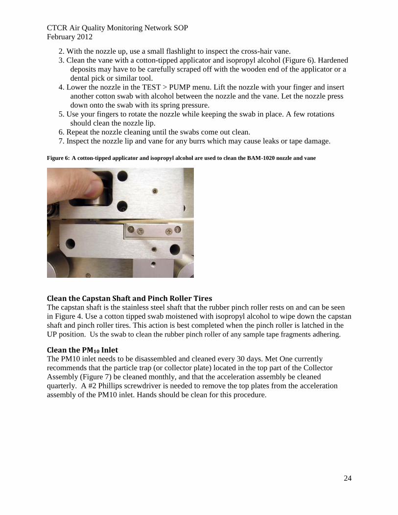
2. With the nozzle up, use a small flashlight to inspect the cross-hair vane.
3. Clean the vane with a cotton-tipped applicator and isopropyl alcohol (Figure 6). Hardened
deposits may have to be carefully scraped off with the wooden end of the applicator or a
dental pick or similar tool.
4. Lower the nozzle in the TEST > PUMP menu. Lift the nozzle with your finger and insert
another cotton swab with alcohol between the nozzle and the vane. Let the nozzle press
down onto the swab with its spring pressure.
5. Use your fingers to rotate the nozzle while keeping the swab in place. A few rotations
should clean the nozzle lip.
6. Repeat the nozzle cleaning until the swabs come out clean.
7. Inspect the nozzle lip and vane for any burrs which may cause leaks or tape damage.
Figure 6: A cotton-tipped applicator and isopropyl alcohol are used to clean the BAM-1020 nozzle and vane
Clean the Capstan Shaft and Pinch Roller Tires The capstan shaft is the stainless steel shaft that the rubber pinch roller rests on and can be seen
in Figure 4. Use a cotton tipped swab moistened with isopropyl alcohol to wipe down the capstan
shaft and pinch roller tires. This action is best completed when the pinch roller is latched in the
UP position. Us the swab to clean the rubber pinch roller of any sample tape fragments adhering.
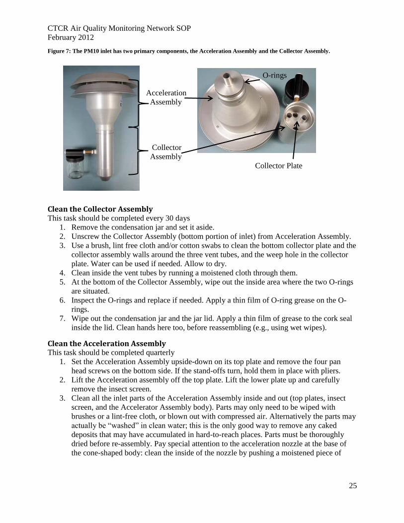
Clean the PM10 Inlet The PM10 inlet needs to be disassembled and cleaned every 30 days. Met One currently
recommends that the particle trap (or collector plate) located in the top part of the Collector
Assembly (Figure 7) be cleaned monthly, and that the acceleration assembly be cleaned
quarterly. A #2 Phillips screwdriver is needed to remove the top plates from the acceleration
assembly of the PM10 inlet. Hands should be clean for this procedure.
CTCR Air Quality Monitoring Network SOP
February 2012
25
Figure 7: The PM10 inlet has two primary components, the Acceleration Assembly and the Collector Assembly.
Acceleration
Assembly
Collector
Assembly
Collector Plate
Clean the Collector Assembly This task should be completed every 30 days
1. Remove the condensation jar and set it aside.
2. Unscrew the Collector Assembly (bottom portion of inlet) from Acceleration Assembly.
3. Use a brush, lint free cloth and/or cotton swabs to clean the bottom collector plate and the
collector assembly walls around the three vent tubes, and the weep hole in the collector
plate. Water can be used if needed. Allow to dry.
4. Clean inside the vent tubes by running a moistened cloth through them.
5. At the bottom of the Collector Assembly, wipe out the inside area where the two O-rings
are situated.
6. Inspect the O-rings and replace if needed. Apply a thin film of O-ring grease on the O-
rings.
7. Wipe out the condensation jar and the jar lid. Apply a thin film of grease to the cork seal
inside the lid. Clean hands here too, before reassembling (e.g., using wet wipes).
Clean the Acceleration Assembly This task should be completed quarterly
1. Set the Acceleration Assembly upside-down on its top plate and remove the four pan
head screws on the bottom side. If the stand-offs turn, hold them in place with pliers.
2. Lift the Acceleration assembly off the top plate. Lift the lower plate up and carefully
remove the insect screen.
3. Clean all the inlet parts of the Acceleration Assembly inside and out (top plates, insect
screen, and the Accelerator Assembly body). Parts may only need to be wiped with
brushes or a lint-free cloth, or blown out with compressed air. Alternatively the parts may
actually be “washed” in clean water; this is the only good way to remove any caked
deposits that may have accumulated in hard-to-reach places. Parts must be thoroughly
dried before re-assembly. Pay special attention to the acceleration nozzle at the base of
the cone-shaped body: clean the inside of the nozzle by pushing a moistened piece of
O-rings
CTCR Air Quality Monitoring Network SOP
February 2012
26
cloth through it. Inspect the large diameter O-ring at the base of the Accelerator
Assembly.
4. Replace the O-ring if necessary, or apply a thin film of O-ring grease on the O-ring and a
thin film on the aluminum threads of the acceleration assembly.
5. To avoid contamination of other items, clean hands with a wet wipe or similar material to
clean off O-ring grease.
6. Reassemble the PM10 inlet.
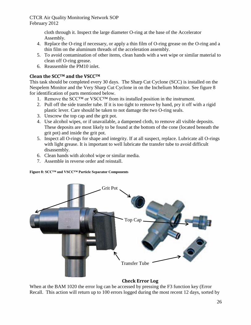
Clean the SCCTM and the VSCCTM This task should be completed every 30 days. The Sharp Cut Cyclone (SCC) is installed on the
Nespelem Monitor and the Very Sharp Cut Cyclone in on the Inchelium Monitor. See figure 8
for identification of parts mentioned below.
1. Remove the SCC™ or VSCC™ from its installed position in the instrument.
2. Pull off the side transfer tube. If it is too tight to remove by hand, pry it off with a rigid
plastic lever. Care should be taken to not damage the two O-ring seals.
3. Unscrew the top cap and the grit pot.
4. Use alcohol wipes, or if unavailable, a dampened cloth, to remove all visible deposits.
These deposits are most likely to be found at the bottom of the cone (located beneath the
grit pot) and inside the grit pot.
5. Inspect all O-rings for shape and integrity. If at all suspect, replace. Lubricate all O-rings
with light grease. It is important to well lubricate the transfer tube to avoid difficult
disassembly.
6. Clean hands with alcohol wipe or similar media.
7. Assemble in reverse order and reinstall.
Figure 8: SCC™ and VSCC™ Particle Separator Components
Check Error Log When at the BAM 1020 the error log can be accessed by pressing the F3 function key (Error
Recall. This action will return up to 100 errors logged during the most recent 12 days, sorted by
Grit Pot
Top Cap
Transfer Tube
CTCR Air Quality Monitoring Network SOP
February 2012
27
date. Utilizing the F3 key will not interrupt the sampling cycle and will not provide a copy of the
log. To download the error log follow the instruction for digital data download below for the
CometTM
program. The error log will also be available by remote access when an external data
acquisition system is in place. Errors more than 12 day old require that data be downloaded
following the process outlined below.
Digital Data Download This process applies to manually downloading data to a laptop computer at the monitoring site
and not by remote access. Data management and analysis will be covered under a separate SOP.
Follow these steps to download the BAM 1020 data via CometTM
:
1. Connect one end of the 9-pin cable to the RS-232 port connector on the Nespelem BAM
1020 (the upper RS232 connector on the back of the unit), and the other to the computer.
To connect the Inchelium BAM use the Report RS-232 port by using the connecting
cable.
2. Ensure that the BAM 1020 user interface is in the main top-level menu or the OPERATE
menu. The serial port is disabled in all other menus.
3. Open the CometTM
program on the laptop and select new to add a station or pick an
existing one. If adding a new station, assign a name, pick the monitor type (BAM 1020),
and designate COM1 with a Baud rate of 9600. Nespelem is designated as site 02 and
Inchelium as site 03.
4. Confirm the station information is correct on the left side of the screen. Press the
Retrieve Current button under Data Options,
5. A Retrieve popup window will appear with choices of files to download; setting, data,
alarm or all. For the majority of downloads check the all box. Under Data Range click
new to download data recorded since the last time. To retrieve all data stored on the
BAM 1020 click on the all button. Downloading may take up to 15 minutes if retrieving
all data.
6. The CometTM
program will then retrieve the designated data.
7. The three file types, setting, data and alarm, can be viewed immediately or from the file
storage location. Use the Open Previous button for a selection of stored files. The
CometTM
program saves setting and alarm files as text and data as cvs. These can easily
be accessed by utilizing Word or Excel.
Two Month Maintenance and QC
Replace Filter Tape Follow the instruction under loading filter tape in the Initial Startup and Check section.
Conduct Self-test Follow the instruction under self-test in the Initial Startup and Check section.
Flow, Temperature and Pressure Calibration Calibrations are recommended every two months unless all values are within operating limits
given above (Table 12). If within the limits no calibration is necessary.
CTCR Air Quality Monitoring Network SOP
February 2012
28
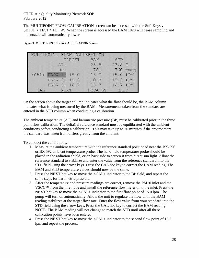
The MULTIPOINT FLOW CALIBRATION screen can be accessed with the Soft Keys via
SETUP > TEST > FLOW. When the screen is accessed the BAM 1020 will cease sampling and
the nozzle will automatically lower.
Figure 9: MULTIPOINT FLOW CALLIBRATION Screen
On the screen above the target column indicates what the flow should be, the BAM column
indicates what is being measured by the BAM. Measurements taken from the standard are
entered in the STD column when conducting a calibration.
The ambient temperature (AT) and barometric pressure (BP) must be calibrated prior to the three
point flow calibration. The deltaCal reference standard must be equilibrated with the ambient
conditions before conducting a calibration. This may take up to 30 minutes if the environment
the standard was taken from differs greatly from the ambient.
To conduct the calibrations:
1. Measure the ambient temperature with the reference standard positioned near the BX-596
or BX 592 ambient temperature probe. The hand-held temperature probe should be
placed in the radiation shield, or on back side to screen it from direct sun light. Allow the
reference standard to stabilize and enter the value from the reference standard into the
STD field using the arrow keys. Press the CAL hot key to correct the BAM reading. The
BAM and STD temperature values should now be the same.
2. Press the NEXT hot key to move the <CAL> indicator to the BP field, and repeat the
same steps for barometric pressure.
3. After the temperature and pressure readings are correct, remove the PM10 inlet and the
VSCC™ from the inlet tube and install the reference flow meter onto the inlet. Press the
NEXT hot key to move the <CAL> indicator to the first flow point of 15.0 lpm. The
pump will turn on automatically. Allow the unit to regulate the flow until the BAM
reading stabilizes at the target flow rate. Enter the flow value from your standard into the
STD field using the arrow keys. Press the CAL hot key to correct the BAM reading.
NOTE: The BAM reading will not change to match the STD until after all three
calibration points have been entered.
4. Press the NEXT hot key to move the <CAL> indicator to the second flow point of 18.3
lpm and repeat the process.
CTCR Air Quality Monitoring Network SOP
February 2012
29
5. Press the NEXT hot key to move the <CAL> indicator to the third flow point of 16.7 lpm
and repeat the process. Enter the flow value and press <CAL>.When all of the
calibrations are complete, the BAM 1020 flow readings should match the traceable flow
standard reading at 16.7 lpm, +/- 0.1 lpm.
6. Exit the calibration menu.
7. A regular flow verification should be performed after the calibration is complete and the
results entered on the flow verification sheet.
The DEFAULT Soft Key will reset the user calibration from the selected parameter and replace
it with a factory setting. If any of the FLOW parameters are selected, the DEFAULT key will
reset the calibrations of all three flow points. This feature can be used to start over with a
calibration if difficulty is encountered.
Verify the BAM 1020 Settings The BAM 1020 settings should be verified every two months by comparing them with the
expected setting shown in Table 13 below. Instrument specific calibration values are listed on
the Calibration Certificate provided with each BAM 1020. A fillable form was created for each
site with the constants and location values filled in (Appendix D).
Table 13: Verify BAM 1020 Settings
BAM-1020 PM2.5 Setup and Calibration Values
Screen Parameter Expected/Default As Found Value Adjusted Value
SETUP > CLOCK Clock Time/Date Local Pacific Standard Time
SETUP > SAMPLE
RS232 9600, 8N1
BAM SAMPLE Nespelem 50 min Inchelium 42 min
STATION # Nespelem 02 Inchelium 03
MET SAMPLE 60 minutes
RANGE 1.000 mg
OFFSET -0.015 mg
CONC UNITS μg/m3
COUNT TIME Nespelem 4 min Inchelium 8 min
SETUP > CALIBRATE
FLOW RATE 16.7 liter per minute
CONC TYPE Actual
FLOW TYPE Actual
Cv Nespelem 0.990 Inchelium 1.022
Qo Nespelem 0.000 Inchelium -0.099
ABS Nespelem 0.791 Inchelium 0.807
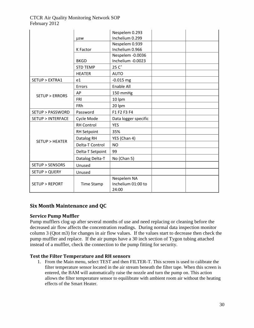
CTCR Air Quality Monitoring Network SOP
February 2012
30
μsw Nespelem 0.293 Inchelium 0.299
K Factor Nespelem 0.939 Inchelium 0.966
BKGD Nespelem -0.0036 Inchelium -0.0023
STD TEMP 25 C˚
HEATER AUTO
SETUP > EXTRA1 e1 -0.015 mg
SETUP > ERRORS
Errors Enable All
AP 150 mmHg
FRl 10 lpm
FRh 20 lpm
SETUP > PASSWORD Password F1 F2 F3 F4
SETUP > INTERFACE Cycle Mode Data logger specific
SETUP > HEATER
RH Control YES
RH Setpoint 35%
Datalog RH YES (Chan 4)
Delta-T Control NO
Delta-T Setpoint 99
Datalog Delta-T No (Chan 5)
SETUP > SENSORS Unused
SETUP > QUERY Unused
SETUP > REPORT Time Stamp Nespelem NA Inchelium 01:00 to 24:00
Six Month Maintenance and QC
Service Pump Muffler Pump mufflers clog up after several months of use and need replacing or cleaning before the
decreased air flow affects the concentration readings. During normal data inspection monitor
column 3 (Qtot m3) for changes in air flow values. If the values start to decrease then check the
pump muffler and replace. If the air pumps have a 30 inch section of Tygon tubing attached
instead of a muffler, check the connection to the pump fitting for security.
Test the Filter Temperature and RH sensors 1. From the Main menu, select TEST and then FILTER-T. This screen is used to calibrate the
filter temperature sensor located in the air stream beneath the filter tape. When this screen is
entered, the BAM will automatically raise the nozzle and turn the pump on. This action
allows the filter temperature sensor to equilibrate with ambient room air without the heating
effects of the Smart Heater.
CTCR Air Quality Monitoring Network SOP
February 2012
31
2. Allow the pump to run for at least 5 minutes to allow the sensor to equilibrate. During this
same period, allow the reference standard temperature sensor to equilibrate with the room
temperature.
3. Press the RESET hot key to clear out any past calibration values.
4. Enter the ambient room temperature from the reference standard into the REFERENCE field
using the arrow keys and press the CALIBRATE hot key. The BAM reading should change
to match within +/- 1 deg C.
5. The RESET hot key can be used to revert to default calibrations and start over if difficulty is
encountered.
To test the filter RH sensor, seldom used or needed.
1. From the Main menu, select TEST and then RH. This screen, which functions exactly like the
FILTER-T screen, is used to calibrate the filter RH sensor located in the air stream beneath
the filter tape.
2. Allow the pump to run for at least 5 minutes to allow the sensor to equilibrate.
3. Press the RESET hot key to clear out any past calibration values.
4. Enter the ambient room relative humidity from the reference standard into the REFERENCE
field and press the CALIBRATE hot key. The BAM reading should change to match within
+/- 4% RH.
5. The RESET hot key can be used to revert to default calibrations and start over if difficulty is
encountered.
Test Smart Heater 1. From the Main menu, select TEST and then HEATER. This screen is used to force the Smart
Heater ON or OFF for testing purposes. The heater takes several minutes to heat up or cool
down noticeably.
2. If the heater is on (warm to the touch), force it off to allow it to cool for several minutes.
Turn it back on and verify that it warms up.
3. If the heater is cool to the touch when it is initially checked, force the heater on and verify
that it warms after several minutes.
4. The heater automatically turns back off upon exit from the screen.
Twelve Month Maintenance and QC
72 hour Background Test The BX-302 zero filter kit is utilized for this test and follows the procedures given in the
instructions. The instructions are included in this document as Appendix E.
Clean or Replace internal debris Filter An internal debris filter is located in the flow path of the BAM 1020 (see diagram in BAM 1020
Operation Manual, Rev G, page 30). This filter element (Met One PN 580292) should be cleaned
or replaced annually.
Check the Membrane Span Foil The BAM-1020 performs a span check each hour by extending the reference membrane so that it
is positioned between the beta source and the scintillation counter. A complete description of this
span check process is given in the BAM 1020 Operation Manual (Rev G) on page 28. The value
of this measurement is displayed on the NORMAL screen as the “LAST m”. The LAST m value
CTCR Air Quality Monitoring Network SOP
February 2012
32
should be very close or equal to the ABS value given on the Calibration certificate. Values in
excess of ±5% are flagged as errors (a “D” error for “Deviant Membrane Density”; also known
as “Cal error”). If the D error bit is set to ON in the SETUP > ERROR screen, the analog voltage
output will also go to full scale.
1. To check the membrane span foil,
2. From the Main menu, choose TEST > CALIBRATE, bringing up the CALIBRATION
MODE screen for the reference membrane;
3. Press the START Soft Key to begin the 8-minute test;
4. When complete, record the Calibration mass;
5. Repeat the test two more times (total three tests);
6. Calculate the average mass; and
7. Compare this value with the ABS value in the SETUP >>CALIBRATE screen.
If the calculated average mass is higher than the ABS value for a particular instrument, this may
indicate that there is a buildup of material on the membrane; either dirt, or water marks, or some
other marking. An average lower than the ABS value could indicate that the high voltage to the
Beta Detector tube is low, the count circuit is malfunctioning, or there is a hole or tear in the
cellophane material. Inspect the reference membrane for signs of damage; if there is damage; call
the Met One Service department.
Perform Beta Detector Count Rate and Dark Count Test The TEST > COUNT screen allows the check of the function of the beta detector and beta source
separate from the rest of the mechanical or flow operations. Each count test will take 4 minutes,
and will show the number of beta particles counted as they accumulate. The final count value
will stay on the display after the counting is finished, and up to six count tests can be displayed
on the screen at once. Count tests are usually performed with a clean section of filter tape
between the source and detector, as in normal operation. The test also allows the membrane to be
extended between the source and detector as well, if desired.
Press the GO Soft Key to start the 4-minute count test. The counting will immediately begin.
After four minutes the counting will stop and wait for the operator to initiate another cycle or
EXIT. The resulting COUNT value is the total number of beta particles counted during the four-
minute test. This count will increment rapidly during the test. Typical 4-minute count values are
between 600,000 and 1,000,000 counts through clean filter tape. The count total will be lower if
the span membrane is extended. If the count total is less than 500,000, the beta detector is
possibly wearing out.
Clean Inlet Tube Proper cleaning of the inlet tube requires that the tube be lifted out of the inlet at the top of the BAM-
1020. Note: take care to protect the inlet of the BAM-1020 receiver from any debris by placing the
red protector over it.
To clean the inlet tube,
1. Remove the PM10 and PM2.5 heads and set aside;
2. Loosen the set screws in the BAM-1020 inlet receiver;
3. Loosen the white cap on the roof mounting flange;
4. Loosen the smart heater set screws and lift out the tub;
CTCR Air Quality Monitoring Network SOP
February 2012
33
5. Drop a rope down the tube, and at the bottom end, tie on a clean cloth that can be pulled up
through the tube to clean the walls;
6. Repeat until clean;
7. Re-install following the instruction given under Installation Procedures.
Independent Audit A full audit, conducted annually by an independent reviewer, will provide added assurance that
the BAM-1020 is being maintained and operated according to best practices. The auditor may be
an individual within an agency not normally responsible for regular maintenance and operation
of the instrument. A truly independent audit by an individual from an external agency is
preferred if arrangements can be made. A form recommended by Met One (Appendix F) will be
used for the full audit documentation.
Replace Lithium Coin Cell Battery The lithium coin cell battery location on the BAM-1020 3032 circuit board should be replaced
annually. This battery provides the power to maintain the BAM-1020 clock and the stored
configuration settings and sample data when the instrument is powered down. When changing
the battery, the operator needs to pay careful attention to the electrical system as the battery must
be changed with the AC power on, otherwise the date/time, data log, and error log will be lost.
Twenty Four Month Maintenance
Rebuild Vacuum Pump The vacuum pump should be rebuilt every two years. The Medo 925A pump is very easy to
rebuild by removing four head bolts, sliding out the old piston and inserting a new one. Pump
rebuild kits are available from Met One (PN 680839).
Replace Nozzle O-rings Replacement of the nozzle O-rings requires special tools found in the BX-308 Service Tool Kit.
Follow the complete instruction accompanying the kit.
Replace Pump Tubing Replace the tubing between the pump and the back of the BAM-1020 at least every two years.
CTCR Air Quality Monitoring Network SOP
February 2012
34
Data Acquisition System A separate SOP will be written after a DAS system has been chosen for the network.
Data Validation and Quality Assurance
Pertinent to data validation and QA protocols for continuous PM2.5 monitoring with the BAM
1020 are the following documents:
1. 40 CFR Part 50 Appendix N (“Interpretation of the National Ambient Air Quality
Standards for PM2.5”)
2. 40 CFR Part 50 Appendix L (“Reference Method for the Determination of Fine
Particulate Matter as PM2.5 in the Atmosphere”)
3. 40 CFR Part 58 Appendix A (“Quality Assurance Requirements for SLAMS, SPMs and
PSD Air Monitoring”)
4. EPA Quality Assurance Guidance Document 2.12 (“Monitoring PM2.5 in Ambient Air
Using Designated Reference or Class I Equivalent Methods”).
These documents offer extensive details about procedures intended to ensure that PM2.5 data
meets data quality objectives (DQO). All documents are on file in the Air Quality Program office
and made available to employees involved with monitoring.
Quality Control Best Practices
The following system comprises the best practices for quality control that will minimize the
occurrence of invalid or no data being recorded. Calendar entries should be used to schedule
these practices and diligently adhered to. A copy of the BAM 1020 manual, schedule of
maintenance, maintenance process instructions and check list sheets are kept current in both
monitor enclosures. Central to the best practices concept is the keeping of a site log for each
monitor (Appendix G). These logs will document all site visits, actions taken and general notes
in as great of detail as possible.
Data Validation
Statistics and settings can be downloaded utilizing the Comet program. Comet automatically
downloads a settings tab with current and standard entries. These can then be compared to what
was expected as shown in the Setup and Calibration Check Form (Appendix D).
For data to be validated and not invalidated it must fall within the guidance provided in Table 14.
Table 14: Critical and operational data validation criteria for the Met One BAM
Criteria Frequency Tolerances Reference
Critical Criteria: These criteria represent the most important sampling attribute data
Sampling period
Hourly Hourly 42 minutes BAM-1020 Manual, Rev
G
24-hr Daily 1008 minutes 40 CFR Part 50 AppL,
Sec 3.3 Flow statistics (in BAM-1020
Average Flow Rate Hourly ±5% of 16.67 lpm
15.87 to 17.54 lpm 40 CFR Part 50 AppL, Sec 7.4; Method 2.12,
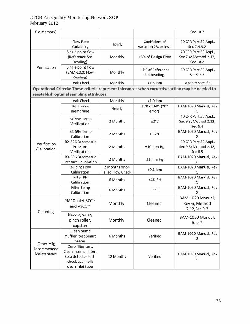
CTCR Air Quality Monitoring Network SOP
February 2012
35
file memory) Sec 10.2
Flow Rate Variability
Hourly Coefficient of
variation 2% or less 40 CFR Part 50 AppL,
Sec 7.4.3.2
Verification
Single point flow (Reference Std
Reading) Monthly ±5% of Design Flow
40 CFR Part 50 AppL, Sec 7.4; Method 2.12,
Sec 10.2 Single point flow (BAM-1020 Flow
Reading) Monthly
±4% of Reference Std Reading
40 CFR Part 50 AppL, Sec 9.2.5
Leak Check Monthly >1.5 lpm Agency specific
Operational Criteria: These criteria represent tolerances when corrective action may be needed to reestablish optimal sampling attributes
Verification /Calibration
Leak Check Monthly >1.0 lpm Reference membrane
Hourly ±5% of ABS (“D”
error) BAM-1020 Manual, Rev
G
BX-596 Temp Verification
2 Months ±2°C 40 CFR Part 50 AppL, Sec 9.3; Method 2.12,
Sec 6.4 BX-596 Temp
Calibration 2 Months ±0.2°C
BAM-1020 Manual, Rev G
BX-596 Barometric Pressure
Verification 2 Months ±10 mm Hg
40 CFR Part 50 AppL, Sec 9.3; Method 2.12,
Sec 6.5 BX-596 Barometric Pressure Calibration
2 Months ±1 mm Hg BAM-1020 Manual, Rev
G 3-Point Flow
Calibration 2 Months or on
Failed Flow Check ±0.1 lpm
BAM-1020 Manual, Rev G
Filter RH Calibration
6 Months ±4% RH BAM-1020 Manual, Rev
G Filter Temp Calibration
6 Months ±1°C BAM-1020 Manual, Rev
G
Cleaning
PM10 Inlet SCC™ and VSCC™
Monthly Cleaned BAM-1020 Manual,
Rev G; Method 2.12,Sec 9.3
Nozzle, vane, pinch roller,
capstan Monthly Cleaned
BAM-1020 Manual, Rev G
Other Mfg Recommended Maintenance
Clean pump muffler; test Smart
heater 6 Months Verified
BAM-1020 Manual, Rev G
Zero filter test, Clean internal filter; Beta detector test;
check span foil; clean inlet tube
12 Months Verified BAM-1020 Manual, Rev
G

CTCR Air Quality Monitoring Network SOP
February 2012
36
Data Validation Steps Table 15 list sequential steps, components and procedures for validation of monitoring data
based on criteria mentioned in several sections above and EPA Quality Assurance Guidance
Document 2.12.
Table 15: Data Validation Steps for BAM 1020
Validation Step Component Procedure
Verify Data Source Direct Data Download
Download csv Data File
Download Settings File
Download Alarm File
Review BAM 1020 Attribute Data
Full scale concentration, Analog data
Sort records for full scale data (0.985 mg); look for errors causing FS output but digital CONC data are valid (e.g., errors P, R, N, E), if found, retrieve digital data.
Full scale concentration, Digital data
Usually maintenance (M) or power fail (L) errors: invalidate
Qtot
A good validation indicator. If Qtot varies, suggests a problem with temperature or pressure probe, or pump. Recommend rigid tolerance for Qtot
Error flags Review specific errors and invalidate accordingly
Review BAM-1020 Flow Statistics
Elapsed time Nespelem 50 minutes Inchelium 42 minutes
Average flow ±4% of 16.67 lpm
Coefficient of variation < 2%
Sample volume Recommend rigid tolerance for Qtot (0.700 ±0.003 m3)
Temperature and Pressure Stats Average, Max, Min for reasonableness
Review Field QC (Operator log
sheets)
Flow checks ±4% of 16.67 lpm
Leak checks > 1.5 lpm, invalidate back to last passing leak check
Calibration At least annually, or on failed verification
Maintenance procedures
Inlet cleaning Verify inlets cleaned (30 days for VSCC™)
Periodic zero test Verify and evaluate
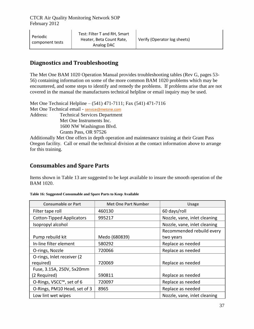
CTCR Air Quality Monitoring Network SOP
February 2012
37
Periodic component tests
Test: Filter T and RH, Smart Heater, Beta Count Rate,
Analog DAC Verify (Operator log sheets)
Diagnostics and Troubleshooting
The Met One BAM 1020 Operation Manual provides troubleshooting tables (Rev G, pages 53-
56) containing information on some of the more common BAM 1020 problems which may be
encountered, and some steps to identify and remedy the problems. If problems arise that are not
covered in the manual the manufactures technical helpline or email inquiry may be used.
Met One Technical Helpline – (541) 471-7111; Fax (541) 471-7116
Met One Technical email - [email protected]
Address: Technical Services Department
Met One Instruments Inc.
1600 NW Washington Blvd.
Grants Pass, OR 97526
Additionally Met One offers in depth operation and maintenance training at their Grant Pass
Oregon facility. Call or email the technical division at the contact information above to arrange
for this training.
Consumables and Spare Parts
Items shown in Table 13 are suggested to be kept available to insure the smooth operation of the
BAM 1020.
Table 16: Suggested Consumable and Spare Parts to Keep Available
Consumable or Part Met One Part Number Usage
Filter tape roll 460130 60 days/roll
Cotton-Tipped Applicators 995217 Nozzle, vane, inlet cleaning
Isopropyl alcohol Nozzle, vane, inlet cleaning
Pump rebuild kit Medo (680839) Recommended rebuild every two years
In-line filter element 580292 Replace as needed
O-rings, Nozzle 720066 Replace as needed
O-rings, Inlet receiver (2 required) 720069 Replace as needed
Fuse, 3.15A, 250V, 5x20mm (2 Required) 590811 Replace as needed
O-Rings, VSCC™, set of 6 720097 Replace as needed
O-Rings, PM10 Head, set of 3 8965 Replace as needed
Low lint wet wipes Nozzle, vane, inlet cleaning
CTCR Air Quality Monitoring Network SOP
February 2012
38
Hand cleaner Tape loading, inlet cleaning
References
EPA Requirements for Quality Assurance Project Plans, EPA QA/R-5, Office of Environmental
Information, Washington DC, EPA/240/B-01/003, March 2001
Guidance for Quality Assurance Project Plans, EPA QA/G5, Office of Environmental
Information, Washington DC, EPA/240/R-02/009, December 2002
Guidance on Systematic Planning Using the Data Quality Objectives Process, EPA QA/G-4,
Office of Environmental Information Washington DC, EPA/240/B-06/0001, February 2006
Guidance for Preparing Standard Operating Procedures (SOPs), EPA QA/G-6, Office of
Environmental Information Washington DC, EPA/6000/B-07/001, April 2007
Met One Instruments, Inc., (2008) BAM 1020 particulate monitor operation manual. Prepared by
Met One Instruments, Inc., Grants Pass, OR, BAM-1020-9800 Rev G.
Standard Operating Procedure for the Continuous Measurement of Particulate Matter, Met One
BAM-1020 PM2.5 Federal Equivalent Method EQPM-0308-170, STI-905505.05-3645-SOP,
David L. Vaughn, Sonoma Technology, Inc.
Technical Guidance for the Development of Tribal Air Monitoring Programs, EPA-456/B-07-
002, August 2007
U.S. Environmental Protection Agency (1998) Quality assurance guidance document 2.12:
Monitoring PM2.5 in ambient air using designated reference or Class I equivalent methods. Prepared
by the Human Exposure and Atmospheric Sciences Division, National Exposure Research
Laboratory, Research Triangle Park, NC, November.
Quality Manual for Environmental Programs, EPA, CIO 2105-P-01-0, May 5, 2005

CTCR Air Quality Monitoring Network SOP
February 2012
39
Appendices