Embed Size (px)
Citation preview
OI-315 TOCSIN3 H2S Personal Monitor ________________________________________
Operation Manual Revision 2.0w
___________________________________________________________________________________________________
___________________________________________________________________________________________________
Product Overview The Otis Instruments Model OI-315 TOCSIN3 H2S Personal Monitor is a safety device designed to detect the presence of H2S in ambient air. When activated, the OI-315 continuously monitors ambient air for the presence of H2S and alerts the user to potentially unsafe exposure with visual, vibrating, and audible alarms. The OI-315 features an alligator clip that allows it to be worn on personnel in the field at all times, as well as: rubber enclosure for shock prevention, water/dust proof enclosure, adjustable alarm set points, LCD display with LED backlight, data logging capability, user-replaceable sensor element, and user-replaceable battery.

3
Table of Contents
Product Overview ............................................................................................................... 2 Introduction ......................................................................................................................... 4 Complete System Diagram ................................................................................................ 4
Complete System ........................................................................................................................................ 4 LCD Display Symbols ................................................................................................................................. 5
Power On ............................................................................................................................. 6 Power Off ............................................................................................................................. 6 Basic Operation .................................................................................................................. 7
Gas Measure Mode .................................................................................................................................... 7 LCD Backlight On/Off .................................................................................................................................. 7 Viewing Date and Time ............................................................................................................................... 7 Setting Date and Time ................................................................................................................................ 8
Alarms and Indicators ........................................................................................................ 9 Setting Alarm .............................................................................................................................................. 9 Default Alarm Set Points ............................................................................................................................. 9 Alarm Displays .......................................................................................................................................... 10 Alarm Indicators ........................................................................................................................................ 10 Returning to Normal Operating Mode Following a Low Alarm .................................................................. 10 Returning to Normal Operating Mode Following a High Alarm ................................................................. 11 Indication of Peak Value and STEL / TWA Value ..................................................................................... 11 Battery Notifications .................................................................................................................................. 11
Data Logging (Alarm Data) .............................................................................................. 12 Fresh Air Calibration ........................................................................................................ 13 Standard Gas Calibration ................................................................................................ 14 Battery Replacement ........................................................................................................ 15 Sensor Element Replacement ......................................................................................... 16 User Notice ........................................................................................................................ 18 Approval Label Notes ....................................................................................................... 18 Specifications ................................................................................................................... 19
4
Introduction
This document is an Operation Manual containing diagrams and step-by-step instructions for proper operation of the Otis Instruments, Inc. Model OI-315 TOCSIN3 H2S Personal Monitor. This document should be read before initial operation of the product.
Should a question arise during the use of the product, this document will serve as a first reference for consultation. If further questions arise, or if the device is not working properly, please contact the sales representative of this product.
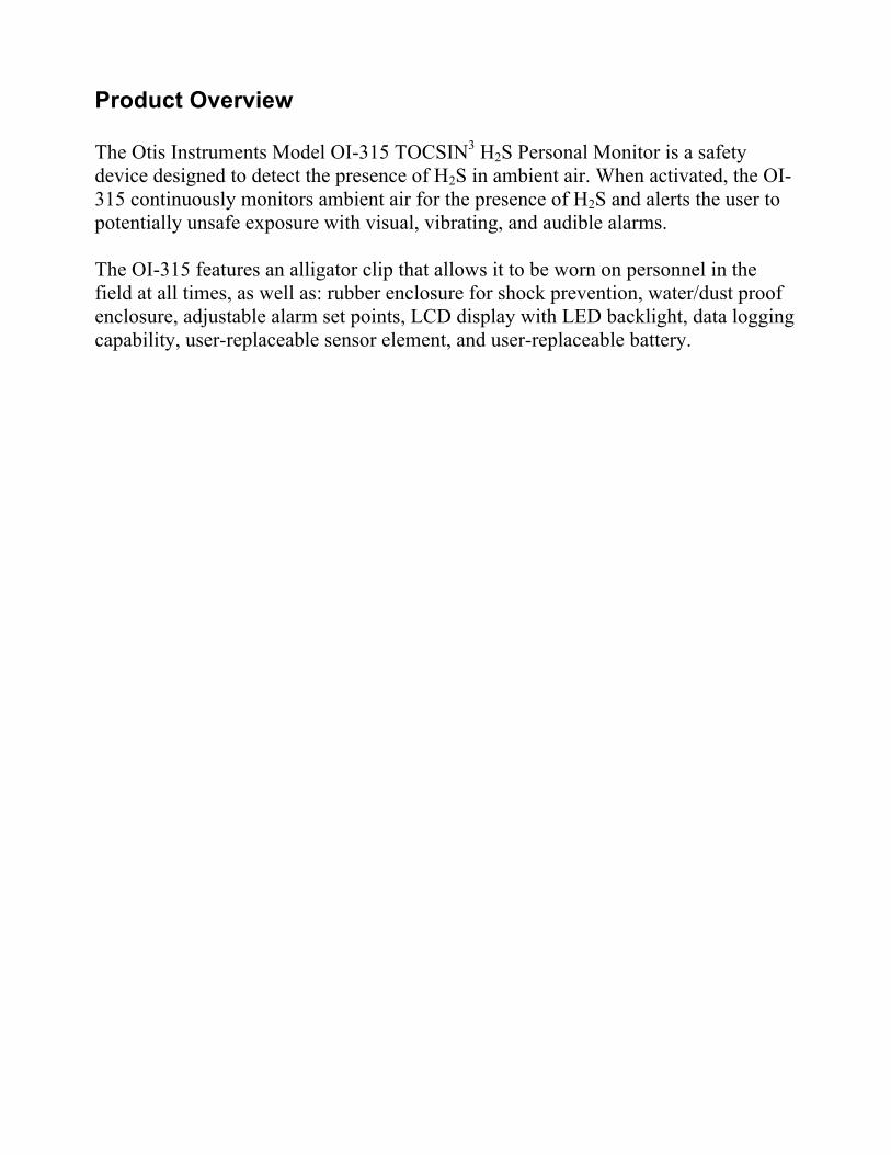
Complete System Diagram The following diagrams should be consulted for identification of the system and all parts that may be referred to in this operation manual.
Complete System
1 Gas sensor 2 Buzzer 3 Green power button 4 Blue arrow button 5 LCD display screen 6 Alarm LED 7 Belt clip 8 Type label
5
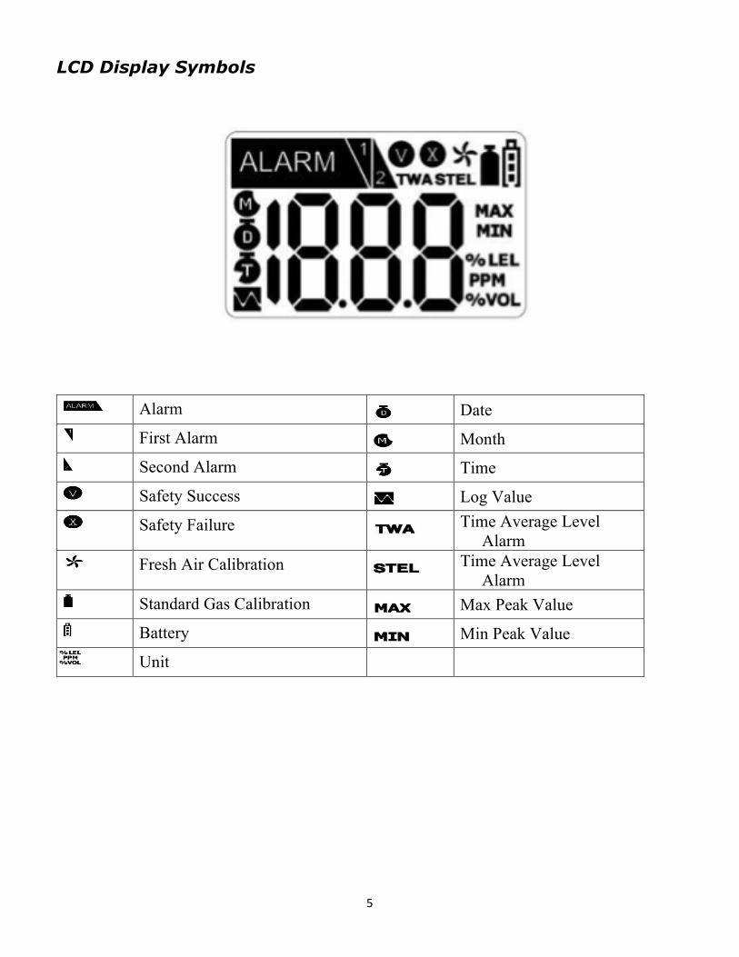
LCD Display Symbols
Alarm Date First Alarm Month Second Alarm Time
Safety Success Log Value Safety Failure Time Average Level
Alarm Fresh Air Calibration Time Average Level
Alarm Standard Gas Calibration Max Peak Value
Battery Min Peak Value Unit
6
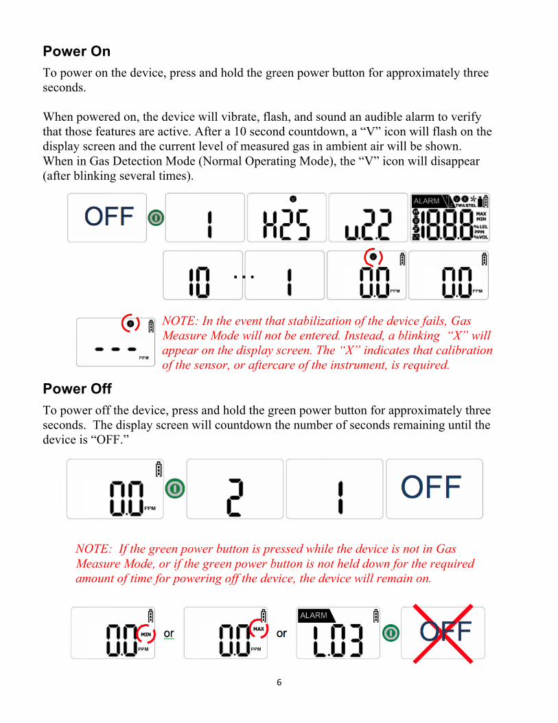
Power On
To power on the device, press and hold the green power button for approximately three seconds. When powered on, the device will vibrate, flash, and sound an audible alarm to verify that those features are active. After a 10 second countdown, a “V” icon will flash on the display screen and the current level of measured gas in ambient air will be shown. When in Gas Detection Mode (Normal Operating Mode), the “V” icon will disappear (after blinking several times).
NOTE: In the event that stabilization of the device fails, Gas Measure Mode will not be entered. Instead, a blinking “X” will appear on the display screen. The “X” indicates that calibration of the sensor, or aftercare of the instrument, is required.
Power Off
To power off the device, press and hold the green power button for approximately three seconds. The display screen will countdown the number of seconds remaining until the device is “OFF.”
NOTE: If the green power button is pressed while the device is not in Gas Measure Mode, or if the green power button is not held down for the required amount of time for powering off the device, the device will remain on.

7
Basic Operation
NOTE: Appropriate calibration of the device is required prior to operation. Always ensure that the device makes the proper detection response to the pertinent gas. Verify that foreign materials that could interfere with the detection of gas are not blocking the area where gas is to be detected.
Gas Measure Mode
Gas Measure Mode is the normal operating mode of the OI-315. When in Gas Measure Mode, the concentration of H2S and remaining battery life are displayed on the screen.
LCD Backlight On/Off
To turn on the LCD backlight, press the blue arrow button while in Gas Measure Mode. To turn off the LCD backlight, press the blue arrow button again (or wait approximately 25 seconds for the backlight to turn off automatically).
Viewing Date and Time
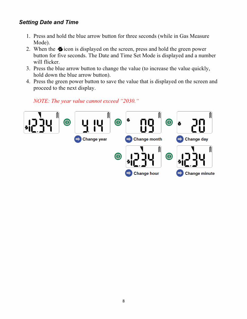
1. Press and hold the blue arrow button for three seconds (while in Gas Measure Mode).
2. When the icon is displayed on the screen, quickly press the blue arrow button. The preset time ( = a.m. and = p.m.), year, month, and day are sequentially confirmed (displayed with the icon or character equivalent of it) with each additional press of the blue arrow button.
3. Press the green power button to return to Gas Measure Mode (or wait several seconds for the device to automatically return).
8
Setting Date and Time
1. Press and hold the blue arrow button for three seconds (while in Gas Measure Mode).
2. When the icon is displayed on the screen, press and hold the green power button for five seconds. The Date and Time Set Mode is displayed and a number will flicker.
3. Press the blue arrow button to change the value (to increase the value quickly, hold down the blue arrow button).
4. Press the green power button to save the value that is displayed on the screen and proceed to the next display.
NOTE: The year value cannot exceed “2030.“
9
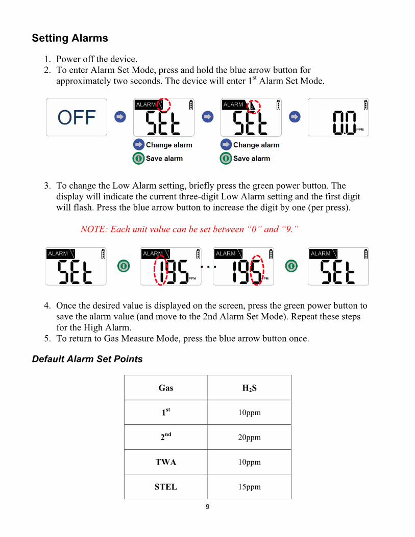
Setting Alarms
1. Power off the device. 2. To enter Alarm Set Mode, press and hold the blue arrow button for
approximately two seconds. The device will enter 1st Alarm Set Mode.
3. To change the Low Alarm setting, briefly press the green power button. The display will indicate the current three-digit Low Alarm setting and the first digit will flash. Press the blue arrow button to increase the digit by one (per press).
NOTE: Each unit value can be set between “0” and “9.”
4. Once the desired value is displayed on the screen, press the green power button to
save the alarm value (and move to the 2nd Alarm Set Mode). Repeat these steps for the High Alarm.
5. To return to Gas Measure Mode, press the blue arrow button once.
Default Alarm Set Points
Gas H2S
1st 10ppm
2nd 20ppm
TWA 10ppm
STEL 15ppm
10
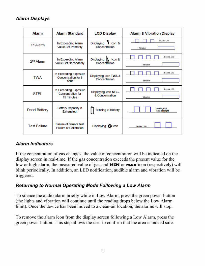
Alarm Displays
Alarm Indicators If the concentration of gas changes, the value of concentration will be indicated on the display screen in real-time. If the gas concentration exceeds the present value for the low or high alarm, the measured value of gas and or icon (respectively) will blink periodically. In addition, an LED notification, audible alarm and vibration will be triggered. Returning to Normal Operating Mode Following a Low Alarm To silence the audio alarm briefly while in Low Alarm, press the green power button (the lights and vibration will continue until the reading drops below the Low Alarm limit). Once the device has been moved to a clean-air location, the alarms will stop. To remove the alarm icon from the display screen following a Low Alarm, press the green power button. This step allows the user to confirm that the area is indeed safe.
11
Returning to Normal Operating Mode Following a High Alarm When a High Alarm has been triggered, the audio alarm cannot be silenced and the alarm icon cannot be removed form the display screen by pressing the green power button. To remove the alarm following a High Alarm, the unit must be moved to a clean-air location and power must be cycled (see the Power Off / Power On sections of this operation manual). Indication of Peak Value and STEL / TWA Value When a STEL (Short Term Exposure Limit) / TWA (Time Weighted Average) Alarm has been triggered, it is indicated with the or icon (respectively), value of the measured gas, an LED notification, audible alarm and vibration. To remove the alarm following a STEL / TWA Alarm, the unit must be moved to a clean-air location and power must be cycled (see the Power Off / Power On sections of this operation manual).
NOTE: All alarm values are set according to the alarm standard of H2S gas (that is required by international standards). Therefore, alarm values can be changed only under the responsibility and approval of the administrator of the work site where the instrument is used.
The maximum value, STEL value, and TWA value will be displayed consecutively while in Gas Measure Mode. Battery Notifications When the battery level is low (one bar remains on the battery icon), an alarm will sound repeatedly at five minute intervals. When the battery is nearly exhausted, a unique combination of audible, LED, and LCD backlight alerts will display for approximately 10 seconds (before the unit turns off completely).

12
Data Logging (Alarm Data)
1. Press the green power button four times while in Gas Measure Mode (Data Log Mode is displayed after minimum, maximum, STEL, and TWA readings).
NOTE: If an alarm event has not yet been recorded on the device, the Data Log Mode screen will not appear. Instead, the device will return to Gas Measure Mode following the final green power button press.
2. Press the blue arrow to enter Data Select Mode. In this mode, data is selected and a record is confirmed.
3. Press the green power button to confirm the year, month, day, time and alarm of the recorded event.
4. To return to the Data Select Mode, press the blue arrow button while the year, month, day, and time are shown on the display screen. To return to Gas Measure Mode, press the green power button.
EXAMPLE: In the reading “L.03” the “L” indicates Log and “03” indicates the number of data. Therefore, in the reading “L.03” there are three events that have been logged.
In Data Select Mode, with “01.1” displayed on the screen, “01” indicates the data instance and “1” indicates the type of alarm that occurred (1 = Low Alarm, 2 = High Alarm). Therefore, in the three instances of data that occurred, the first instance was of a Low Alarm.
13
To view the second, third, etc. sets of recorded data, press the blue arrow button. After the last data reading has been displayed, press the blue arrow button to return to Gas Measure Mode. NOTE: Up to 20 data events can be stored on a device. Once 20 events are stored, data is removed automatically in the order that it was received (starting at Event 1).
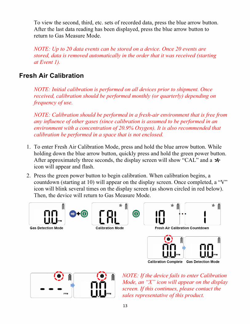
Fresh Air Calibration
NOTE: Initial calibration is performed on all devices prior to shipment. Once received, calibration should be performed monthly (or quarterly) depending on frequency of use.
NOTE: Calibration should be performed in a fresh-air environment that is free from any influence of other gases (since calibration is assumed to be performed in an environment with a concentration of 20.9% Oxygen). It is also recommended that calibration be performed in a space that is not enclosed.
1. To enter Fresh Air Calibration Mode, press and hold the blue arrow button. While holding down the blue arrow button, quickly press and hold the green power button. After approximately three seconds, the display screen will show “CAL” and a icon will appear and flash.
2. Press the green power button to begin calibration. When calibration begins, a countdown (starting at 10) will appear on the display screen. Once completed, a “V” icon will blink several times on the display screen (as shown circled in red below). Then, the device will return to Gas Measure Mode.
NOTE: If the device fails to enter Calibration Mode, an “X” icon will appear on the display screen. If this continues, please contact the sales representative of this product.

14
Standard Gas Calibration
NOTE: Initial calibration is performed on all devices prior to shipment. Once received, calibration should be performed monthly (or quarterly) depending on frequency of use.
1. To enter Standard Gas Calibration Mode, press and hold the blue arrow button. While holding down the blue arrow button, quickly press and hold the green power button. After approximately three seconds, the display screen will show “CAL” and a icon will appear and flash.
2. Press the blue arrow button. A icon will appear. 3. Press and hold the green power button for several seconds. The current calibration
gas value will appear on the display screen. Press the blue arrow button to change the value to match the calibration gas (if necessary).
4. Press the green power button to save each of the three values and start calibration. A 90 second countdown will begin. If the calibration is normally executed, the concentration value of the connected gas is indicated on the display screen with a “V” icon.
NOTE: The concentration of calibration gas (set to device) is 50 ppm.
5. Disconnect the calibration gas. The device will return to Gas Measure Mode (the display screen will indicate the current concentration of gas and the remaining battery life of the device).
NOTE: If the device fails to enter Calibration Mode, an “X” icon will appear on the display screen. If this continues, please contact the sales representative of this product.
15
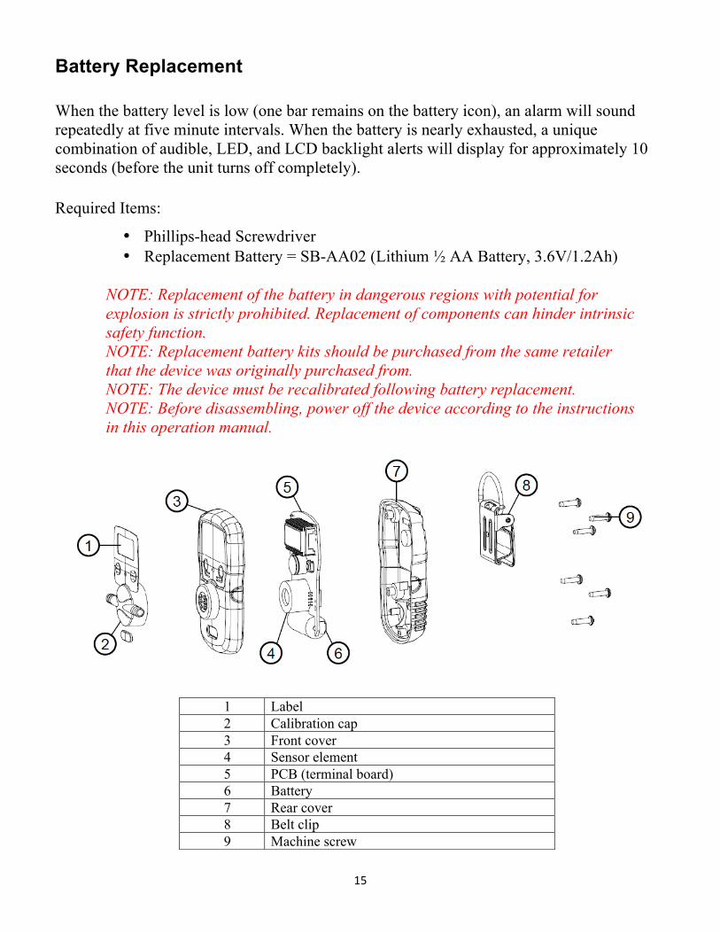
Battery Replacement When the battery level is low (one bar remains on the battery icon), an alarm will sound repeatedly at five minute intervals. When the battery is nearly exhausted, a unique combination of audible, LED, and LCD backlight alerts will display for approximately 10 seconds (before the unit turns off completely). Required Items:
• Phillips-head Screwdriver • Replacement Battery = SB-AA02 (Lithium ½ AA Battery, 3.6V/1.2Ah)
NOTE: Replacement of the battery in dangerous regions with potential for
explosion is strictly prohibited. Replacement of components can hinder intrinsic safety function.
NOTE: Replacement battery kits should be purchased from the same retailer that the device was originally purchased from.
NOTE: The device must be recalibrated following battery replacement. NOTE: Before disassembling, power off the device according to the instructions
in this operation manual.
1 Label 2 Calibration cap 3 Front cover 4 Sensor element 5 PCB (terminal board) 6 Battery 7 Rear cover 8 Belt clip 9 Machine screw

16
1. Remove the five machine screws located on the rear cover of the device. 2. Separate the rear cover from the front cover by gently pulling them away from
each other. 3. Using your thumb and forefinger, pull the battery out of the terminal board. 4. Slide a new battery into the terminal board. 5. Verify that the “+” and “-” sides of the battery are facing the correct direction
(and touching the battery contacts on the terminal board). 6. Place the front and rear covers together, then replace the five machine screws.
Sensor Element Replacement Sensor replacement is recommended every two years (or whenever the “X” icon appears on the display indicating that either the automatic sensor test on start-up, or the “fresh air” calibration process, has failed). Required Items:
• Phillips-head Screwdriver • Replacement Sensor Element = Senko SS series • Replacement Filters
NOTE: Replacement of components can hinder intrinsic safety function. NOTE: Replacement sensor elements should be purchased from the same
retailer that the device was originally purchased from. NOTE: The device must be recalibrated following battery or sensor element
replacement. NOTE: Before disassembling, power off the device according to the instructions
in this operation manual.

17
1. Remove the five machine screws located on the rear cover of the device.
2. Separate the rear cover from the front cover by gently pulling them away from each other.
3. Carefully separate the PCB (terminal board) from the front cover.
4. Using your thumb and forefinger, gently pull the sensor element off of the terminal board.
5. Align the sensor element prongs of a new sensor element with the eyelets on the terminal board. Slide the senor element into place.
6. Place the terminal board back into the front cover.
7. Place the front and rear covers together, then replace the five machine screws.
1 Label 2 Calibration cap 3 Front cover 4 Sensor element 5 PCB (terminal board) 6 Battery 7 Rear cover 8 Belt clip 9 Machine screw
18
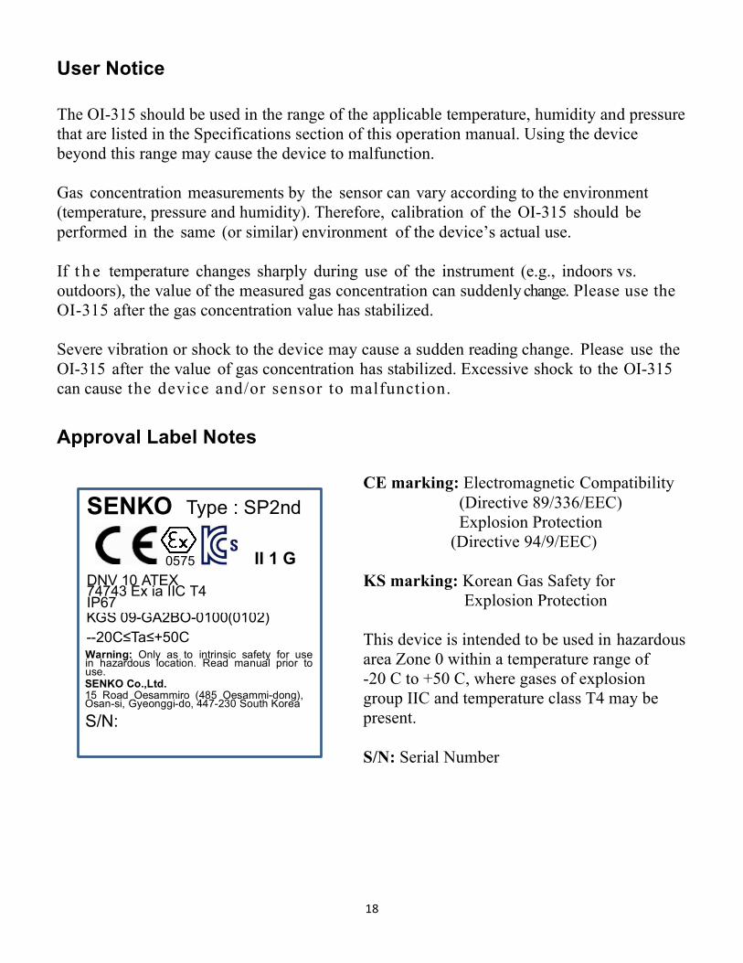
User Notice The OI-315 should be used in the range of the applicable temperature, humidity and pressure that are listed in the Specifications section of this operation manual. Using the device beyond this range may cause the device to malfunction. Gas concentration measurements by the sensor can vary according to the environment (temperature, pressure and humidity). Therefore, calibration of the OI-315 should be performed in the same (or similar) environment of the device’s actual use. If t h e temperature changes sharply during use of the instrument (e.g., indoors vs. outdoors), the value of the measured gas concentration can suddenly change. Please use the OI-315 after the gas concentration value has stabilized. Severe vibration or shock to the device may cause a sudden reading change. Please use the OI-315 after the value of gas concentration has stabilized. Excessive shock to the OI-315 can cause the device and/or sensor to malfunction. Approval Label Notes
CE marking: Electromagnetic Compatibility (Directive 89/336/EEC) Explosion Protection (Directive 94/9/EEC)
KS marking: Korean Gas Safety for
Explosion Protection
This device is intended to be used in hazardous area Zone 0 within a temperature range of -20 C to +50 C, where gases of explosion group IIC and temperature class T4 may be present.
S/N: Serial Number
SENKO
0575 DNV A EX
ia
II 1 G
K -GA2BO- --20C≤Ta≤+50C
nin Onl as in insi saf f use in dous l ion ead manual i use
NKO Ltd oad Oes o Oes -don
Osan- yeonggi- - Sou K ea
S/N:

19
Specifications Measuring Gas: H2S Measuring Range: 0-100 ppm Sensor Life: > 2 years Response Time: < 30 sec/90% scale Accuracy: +/- 3%/full scale Resolution: 0.1 ppm Measuring Type: Diffusion Measuring Method: Electrochemical Parameter Control: Front 2-switch (calibration, maintenance, alarm setting) Operation Mode Display: Visual: digital LCD display, red LED Audible: buzzer (90 dB @ 10 cm)
Measuring Value Display: 3-digit LCD display Alarm Display: Visual: alarm and status icon, red LED Audible: buzzer
Alarm Level Set: Programmable within detection range Data Log: Event Log: 20 alarm events Mounting Type: Belt clip Programmable Set Modes: Alarm value (low and high alarm) Date and time Calibration
Operating Temperature: -20° C to 50° C (-4° F to 122° F) Operating Humidity: 5% to 95% RH (non-condensing) Operating Power: CR2 Lithium battery 3V OR
SB-AA02 Lithium battery 1/2 AA, 3.6v/1.2Ah Battery Life: 1.2 years (8 hours of use per day) LCD Size: 1.06” W x .69” H (27 mm W x 17.5 mm H) Dimensions: 2.13” W x 3.58” H x 1.26” D
(54 mm W x 91 mm H x 32 mm D) Weight: 4.23 oz. (120 g) including battery Approval: Ex ia IIC T4 IP67 (KGS, ATEX) Warranty: One year
20
Warranty Statement for the Model OI-315
Hardware
Otis Instruments, Inc. warrants the OI-315 TOCSIN3 to be free of defects in workmanship and materials—under normal use and service—for one year from the date of purchase from the manufacturer or from the product's authorized reseller.*
The manufacturer is not liable (under this warranty) if its testing and examination disclose that the alleged defect in the product does not exist or was caused by the purchaser's (or any third party's) misuse, neglect, or improper installation, testing or calibrations. Any unauthorized attempt to repair or modify the product, or any other cause of damage beyond the range of the intended use, including damage by fire, lightening, water damage or other hazard, voids liability of the manufacturer.
In the event that a product should fail to perform up to manufacturer specifications during the applicable warranty period, please contact the product's authorized reseller—or visit the “Service” page at www.otisinstruments.com for repair/return information.
Any repaired or replaced product or part has either a 90-day warranty or the remainder of the initial warranty period (whichever is longer).
*The OI-315 battery is not covered under this warranty.

21
Otis Instruments, Inc. 301 S Texas Ave. Bryan, TX 77803
Service Department: 903.566.1300
Corporate Office: 979.776.7700
[email protected] www.otisinstruments.com