Embed Size (px)
Citation preview
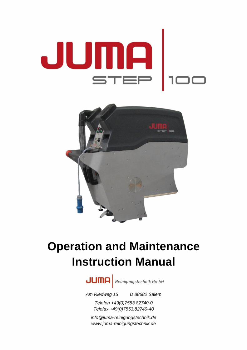
Operation and Maintenance
Instruction Manual
Am Riedweg 15 D 88682 Salem
Telefon +49(0)7553.82740-0
Telefax +49(0)7553.82740-40
www.juma-reinigungstechnik.de
STEP 100 | Operation and Maintenance Instruction Manual
Seite 2 von 31
JUMA Reinigungstechnik GmbH
Am Riedweg 15
88682 Salem
Germany
Stand 01.12.2013
The manufacturer reserves the right to make adjustments to the machine.
This Operation and Maintenance Instruction Manual is intended for service personnel only!
Preliminary remarks
Safety and reliability are absolutely essential to guarantee a long and trouble-free service life of the
STEP 100. In order to fulfil these requirements, the operator must obtain sufficient skill in handling the
machine, its maintenance and care. It is therefore vital that the operator receives instruction and train-
ing from JUMA Reinigungstechnik GmbH specialists before the cleaning machine is started for the first
time.
The present Operation and Maintenance Instruction Manual represent additional assistance for the
operator in obtaining the information necessary for correct and safe use of the cleaning machine.
The nearest customer service centre should be informed immediately if some technical fault in this
cleaning machine should occur.
STEP 100 | Operation and Maintenance Instruction Manual
Seite 3 von 31
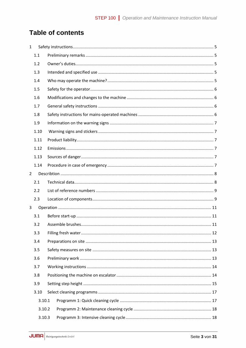
Table of contents 1 Safety instructions ........................................................................................................................... 5
1.1 Preliminary remarks ................................................................................................................ 5
1.2 Owner’s duties......................................................................................................................... 5
1.3 Intended and specified use ..................................................................................................... 5
1.4 Who may operate the machine? ............................................................................................. 5
1.5 Safety for the operator ............................................................................................................ 6
1.6 Modifications and changes to the machine ............................................................................ 6
1.7 General safety instructions ..................................................................................................... 6
1.8 Safety instructions for mains-operated machines .................................................................. 6
1.9 Information on the warning signs ........................................................................................... 7
1.10 Warning signs and stickers ..................................................................................................... 7
1.11 Product liability........................................................................................................................ 7
1.12 Emissions ................................................................................................................................. 7
1.13 Sources of danger .................................................................................................................... 7
1.14 Procedure in case of emergency ............................................................................................. 7
2 Describtion ...................................................................................................................................... 8
2.1 Technical data.......................................................................................................................... 8
2.2 List of reference numbers ....................................................................................................... 9
2.3 Location of components .......................................................................................................... 9
3 Operation ...................................................................................................................................... 11
3.1 Before start-up ...................................................................................................................... 11
3.2 Assemble brushes .................................................................................................................. 11
3.3 Filling fresh water .................................................................................................................. 12
3.4 Preparations on site .............................................................................................................. 13
3.5 Safety measures on site ........................................................................................................ 13
3.6 Preliminary work ................................................................................................................... 13
3.7 Working instructions ............................................................................................................. 14
3.8 Positioning the machine on escalator ................................................................................... 14
3.9 Setting step height ................................................................................................................ 15
3.10 Select cleaning programms ................................................................................................... 17
3.10.1 Programm 1: Quick cleaning cycle ................................................................................ 17
3.10.2 Programm 2: Maintenance cleaning cycle .................................................................... 18
3.10.3 Programm 3: Intensive cleaning cycle ........................................................................... 18
STEP 100 | Operation and Maintenance Instruction Manual
Seite 4 von 31
3.11 Cleaning the escalator ........................................................................................................... 18
3.12 Subsequent cleaning ............................................................................................................. 21
3.13 Refilling with fresh water ...................................................................................................... 21
3.14 Emptying the dirty-water tanks ............................................................................................. 21
3.15 Ending the cleaning process .................................................................................................. 22
3.16 Use of transport trolley ......................................................................................................... 23
3.16.1 Preparation for transport .............................................................................................. 23
3.16.2 Use of transport trolley for maintenance...................................................................... 24
4 Maintenance / Care ....................................................................................................................... 26
4.1 Safety measures during cleaning and maintenance of the machine .................................... 26
4.2 Daily care ............................................................................................................................... 26
4.3 Weekly care ........................................................................................................................... 26
4.4 Maintenance after 30 service hours ..................................................................................... 26
4.5 Maintenance after 100 service hours ................................................................................... 27
4.6 Anumal maintenance ............................................................................................................ 28
4.6.1 Tightening the chain ...................................................................................................... 28
4.6.2 Cleaning and replacing fresh water nozzles .................................................................. 29
4.7 Troubleshooting and remedy ................................................................................................ 30
5 Notizen .......................................................................................................................................... 31
STEP 100 | Operation and Maintenance Instruction Manual
Seite 5 von 31
1 Safety instructions
1.1 Preliminary remarks
The escalator deep cleaning machine STEP 100 was manufactured according to state-of-
the-art technology and in compliance with all relevant regulations. This, however, does not
guarantee that some other unavoidable dangers for persons and property can occur. All per-
sonnel working with this machine must therefore read and follow these operating instructions,
and in particular the safety regulations, with great care.
These operating instructions must remain at the machine for use by the operator. Each oper-
ator must receive thorough instruction on handling and working with the machine.
1.2 Owner’s duties
In accordance with EU directive on the use of operating equipment 89/655/EEC Art. 6(1) and
7 and EU framework directive 89/391/EEC Art. 1(1) and Art. 6(1), the owner of the equipment
is obliged to instruct all persons, particularly with regard to safety, who will be authorised to
work on assembly, operation, maintenance, repair or dismantling of the machine.
The owner is also obliged in accordance with EU directive on the use of operating equipment
89/655/EEC Art. 4a to inspect the machine before start-up, following repair work and follow-
ing faults or malfunction.
1.3 Intended and specified use
The escalator deep cleaning machine STEP 100 is exclusively intended for basic and
maintenance cleaning of indoor and outdoor escalators. Any use beyond this stipulation must
be considered as contrary to the manufacturer’s intentions. The manufacturer will not be lia-
ble for any damage resulting from such work; all risk in this case will be borne exclusively by
the operator. Correct use of the machine also includes compliance with the conditions of op-
eration and maintenance stipulated by the manufacturer.
The escalator deep cleaning machine STEP 100 is not intended nor suitable for
cleaning hazardous dirt.
The machine may only be used with the cleaning liquid approved by the manufactur-
er.
The machine is not fire-proof.
The machine is also not licensed for use in cleaning public streets and paths.
1.4 Who may operate the machine?
The machine may only be used by persons who have been instructed in its operation and
who are expressly authorised to carry out such work. These persons should be at least 18
years old.
All relevant accident prevention regulations and other generally recognised rules of safety
engineering, industrial medicine and the highway code must be strictly observed.
Assembly, equipment, maintenance and repair work demand special knowledge and may
only be carried out by specially trained experts.
STEP 100 | Operation and Maintenance Instruction Manual
Seite 6 von 31
1.5 Safety for the operator
The user must under no circumstances touch the plug of the power supply with damp
hands.
When the machine is being disconnected from the power network, only the plug itself
may be pulled - never the power cable.
The machine may be repaired or opened only by qualified electricians.
If work on the opened machine with connected current is absolutely neces-
sary, such work may be carried out only by a qualified electrician who is famil-
iar with all attendant dangers and the relevant work stipulations (VDE0100).
When work is carried out on machine or parts when live, only tools specially
intended for this purpose may be used.
1.6 Modifications and changes to the machine
It is forbidden for reasons of safety to carry out modifications to this machine. Any unauthor-
ised modifications to the machine automatically invalidate all liability claims against the man-
ufacturer for any damage caused by the modified machine.
Original parts and accessories have been specially designed for this machine. Parts and fit-
tings made by other manufacturers have not been tested by us and are therefore not ap-
proved for use. Assembly and installation of such parts could impair the safety and the per-
fect functioning of the machine. JUMA Reinigungstechnik GmbH expressly refuses to accept
liability for any damage resulting from the use of non-original parts and accessories.
1.7 General safety instructions
When the machine is not in use, its must always be locked away and the key re-
moved.
If it is not possible to lock away the machine, some other suitable measures must be
taken to prevent unauthorised use.
Neither the electrical nor mechanical safety devices on the machine may be changed
or put out of action.
It must be ensured that no other persons, in particular children, are in the vicinity of
the machine when it is in operation.
The machine may only be transported in elevators whose permitted load is adequate
for this purpose.
1.8 Safety instructions for mains-operated machines
Care must be taken that the mains cable incurs no damage by being crushed, torn, frayed,
driven over, etc. This connection must be examined regularly for damage, bare points,
scorched areas, etc. The machine may not be used unless the mains connections is in per-
fect condition. The plug must always be disconnected prior to any cleaning or maintenance
work on the machine, or when accessories are being fitted and replaced. When parts, such
as brushes, mains connection cables, plugs, etc. are being replaced, all technical data pro-
vided by the manufacturer must be observed and only original spare parts used; otherwise
safety of the machine could be impaired. If the power cable is damaged, it must be replaced
by a service workshop approved by the manufacturer as special tools are required for such
work.
STEP 100 | Operation and Maintenance Instruction Manual
Seite 7 von 31
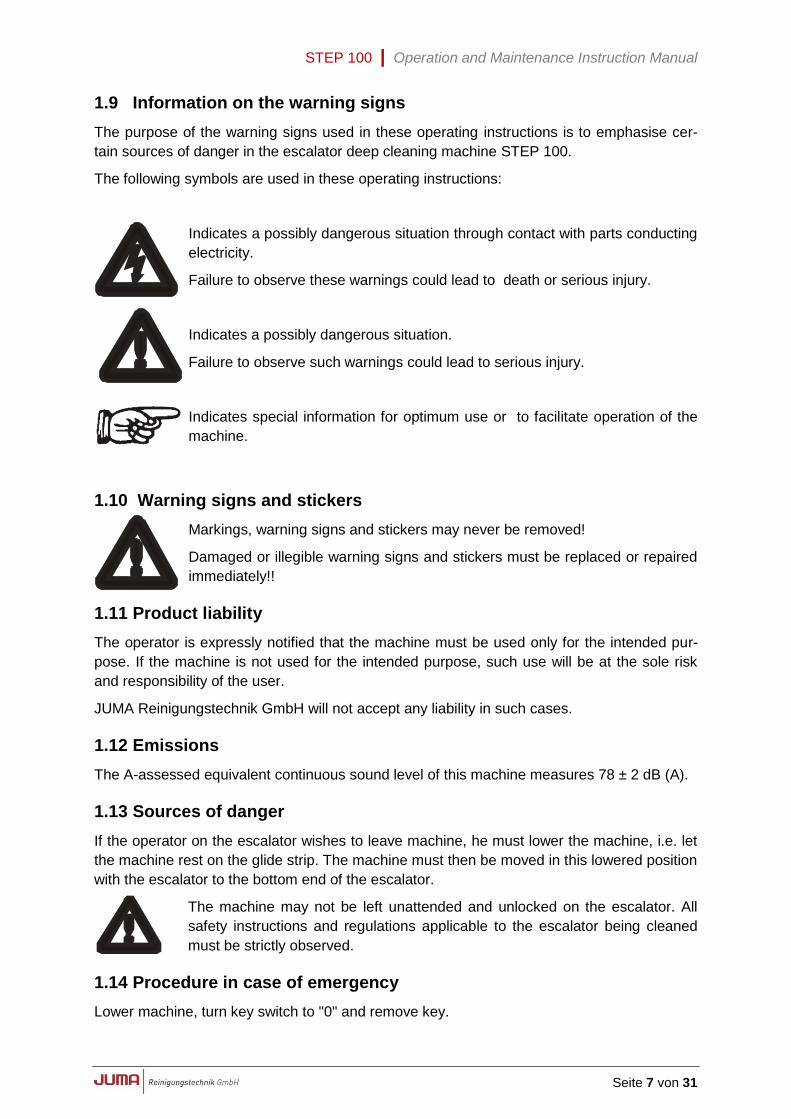
1.9 Information on the warning signs
The purpose of the warning signs used in these operating instructions is to emphasise cer-
tain sources of danger in the escalator deep cleaning machine STEP 100.
The following symbols are used in these operating instructions:
Indicates a possibly dangerous situation through contact with parts conducting
electricity.
Failure to observe these warnings could lead to death or serious injury.
Indicates a possibly dangerous situation.
Failure to observe such warnings could lead to serious injury.
Indicates special information for optimum use or to facilitate operation of the
machine.
1.10 Warning signs and stickers
Markings, warning signs and stickers may never be removed!
Damaged or illegible warning signs and stickers must be replaced or repaired
immediately!!
1.11 Product liability
The operator is expressly notified that the machine must be used only for the intended pur-
pose. If the machine is not used for the intended purpose, such use will be at the sole risk
and responsibility of the user.
JUMA Reinigungstechnik GmbH will not accept any liability in such cases.
1.12 Emissions
The A-assessed equivalent continuous sound level of this machine measures 78 ± 2 dB (A).
1.13 Sources of danger
If the operator on the escalator wishes to leave machine, he must lower the machine, i.e. let
the machine rest on the glide strip. The machine must then be moved in this lowered position
with the escalator to the bottom end of the escalator.
The machine may not be left unattended and unlocked on the escalator. All
safety instructions and regulations applicable to the escalator being cleaned
must be strictly observed.
1.14 Procedure in case of emergency
Lower machine, turn key switch to "0" and remove key.
STEP 100 | Operation and Maintenance Instruction Manual
Seite 8 von 31
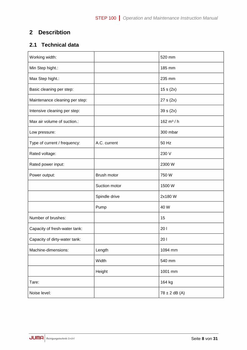
2 Describtion
2.1 Technical data
Working width: 520 mm
Min Step hight.: 185 mm
Max Step hight.: 235 mm
Basic cleaning per step: 15 s (2x)
Maintenance cleaning per step: 27 s (2x)
Intensive cleaning per step: 39 s (2x)
Max air volume of suction.: 162 m³ / h
Low pressure: 300 mbar
Type of current / frequency: A.C. current 50 Hz
Rated voltage: 230 V
Rated power input: 2300 W
Power output: Brush motor 750 W
Suction motor 1500 W
Spindle drive 2x180 W
Pump 40 W
Number of brushes: 15
Capacity of fresh-water tank: 20 l
Capacity of dirty-water tank: 20 l
Machine-dimensions: Length 1094 mm
Width 540 mm
Height 1001 mm
Tare: 164 kg
Noise level: 78 ± 2 dB (A)
STEP 100 | Operation and Maintenance Instruction Manual
Seite 9 von 31
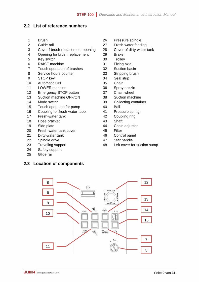
2.2 List of reference numbers
1 Brush 26 Pressure spindle
2 Guide rail 27 Fresh-water feeding
3 Cover f brush-replacement opening 28 Cover of dirty-water tank
4 Opening for brush replacement
29 Brake
5 Key switch 30 Trolley
6 RAISE machine 31 Fixing axle
7 Touch operation of brushes 32 Suction basin
8 Service hours counter 33 Stripping brush
9 STOP key 34 Seal strip
10 Automatic ON 35 Chain
11 LOWER machine 36 Spray nozzle
12 Emergency STOP button 37 Chain wheel
13 Suction machine OFF/ON 38 Suction machine
14 Mode switch 39 Collecting container
15 Touch operation for pump 40 Ball
16 Coupling for fresh-water-tube 41 Pressure spring
17 Fresh-water tank 42 Coupling ring
18 Hose bracket 43 Shaft
19 Side plate 44 Chain adjuster
20 Fresh-water tank cover 45 Filter
21 Dirty-water tank 46 Control panel
22 Spindle drive 47 Star handle
23 Traveling support
48 Left cover for suction sump
24 Safety support
25 Glide rail
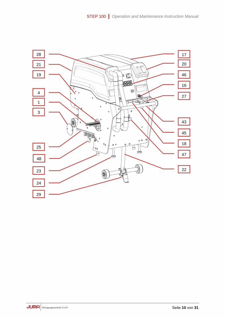
2.3 Location of components
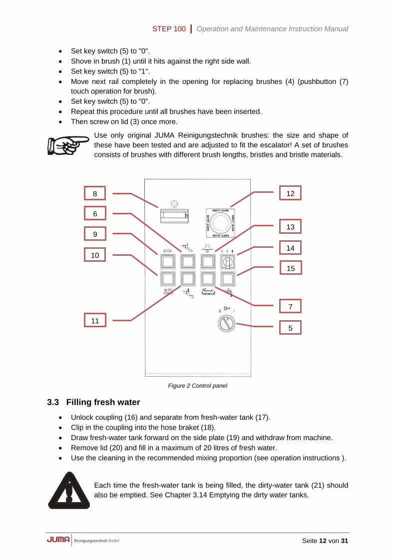
8
6
9
10
11
12
13
14
15
7
5
STEP 100 | Operation and Maintenance Instruction Manual
Seite 10 von 31
21
19
1
3
28
23
24
25
29
27
17
20
18
22
16
4
43
45
46
48 47
STEP 100 | Operation and Maintenance Instruction Manual
Seite 11 von 31
3 Operation
3.1 Before start-up
All local safety regulations and instructions must be observed for each start-up.
The escalator must be inspected jointly with the party responsible for the escalator, who
should also be informed of any discoloration or paint stains etc. caused by repair and renew-
al work..
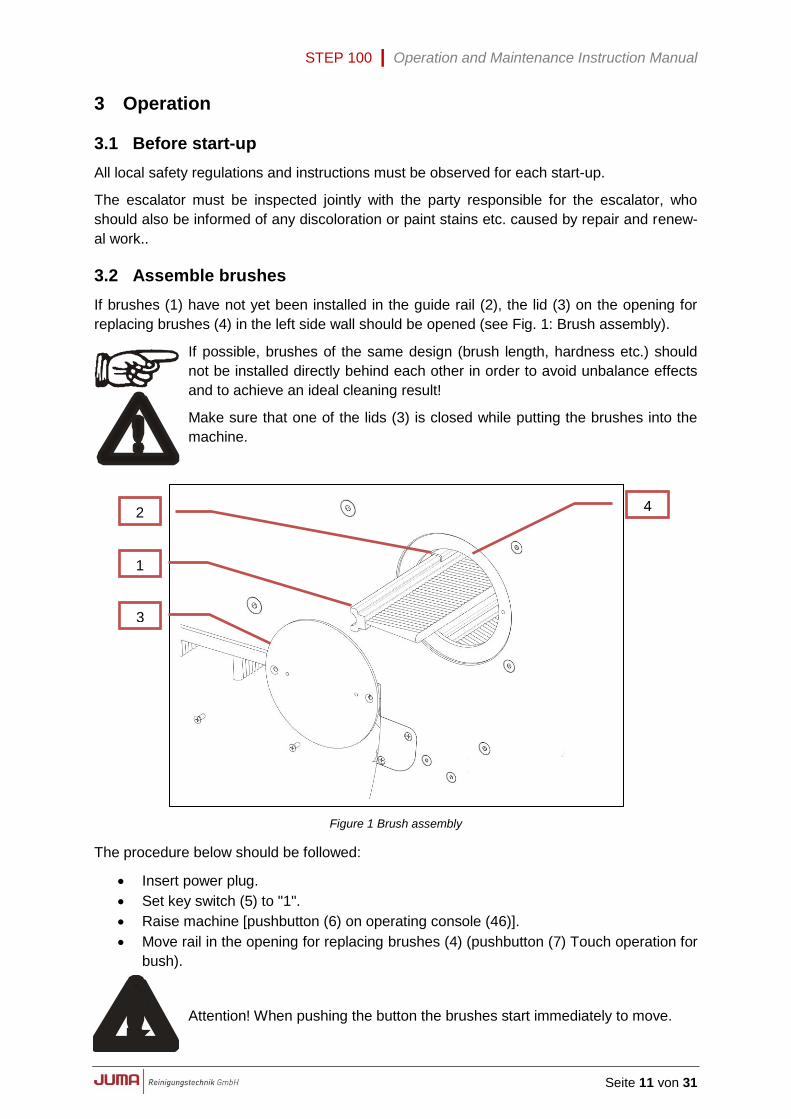
3.2 Assemble brushes
If brushes (1) have not yet been installed in the guide rail (2), the lid (3) on the opening for
replacing brushes (4) in the left side wall should be opened (see Fig. 1: Brush assembly).
If possible, brushes of the same design (brush length, hardness etc.) should
not be installed directly behind each other in order to avoid unbalance effects
and to achieve an ideal cleaning result!
Make sure that one of the lids (3) is closed while putting the brushes into the
machine.
Figure 1 Brush assembly
The procedure below should be followed:
Insert power plug.
Set key switch (5) to "1".
Raise machine [pushbutton (6) on operating console (46)].
Move rail in the opening for replacing brushes (4) (pushbutton (7) Touch operation for
bush).
Attention! When pushing the button the brushes start immediately to move.
1
2
3
4
STEP 100 | Operation and Maintenance Instruction Manual
Seite 12 von 31
Set key switch (5) to "0".
Shove in brush (1) until it hits against the right side wall.
Set key switch (5) to "1".
Move next rail completely in the opening for replacing brushes (4) (pushbutton (7)
touch operation for brush).
Set key switch (5) to "0".
Repeat this procedure until all brushes have been inserted.
Then screw on lid (3) once more.
Use only original JUMA Reinigungstechnik brushes: the size and shape of
these have been tested and are adjusted to fit the escalator! A set of brushes
consists of brushes with different brush lengths, bristles and bristle materials.
Figure 2 Control panel
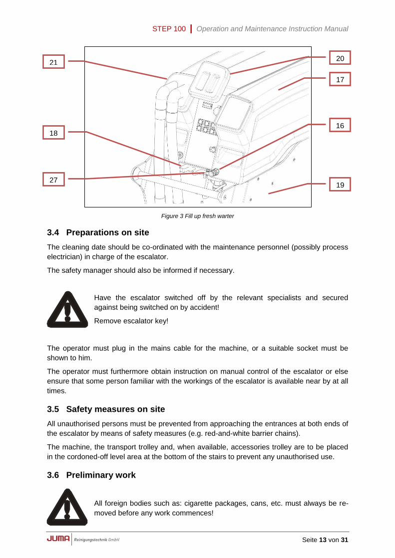
3.3 Filling fresh water
Unlock coupling (16) and separate from fresh-water tank (17).
Clip in the coupling into the hose braket (18).
Draw fresh-water tank forward on the side plate (19) and withdraw from machine.
Remove lid (20) and fill in a maximum of 20 litres of fresh water.
Use the cleaning in the recommended mixing proportion (see operation instructions ).
Each time the fresh-water tank is being filled, the dirty-water tank (21) should
also be emptied. See Chapter 3.14 Emptying the dirty water tanks.
8
6
9
10
11
12
13
14
15
7
5
STEP 100 | Operation and Maintenance Instruction Manual
Seite 13 von 31
Figure 3 Fill up fresh warter
3.4 Preparations on site
The cleaning date should be co-ordinated with the maintenance personnel (possibly process
electrician) in charge of the escalator.
The safety manager should also be informed if necessary.
Have the escalator switched off by the relevant specialists and secured
against being switched on by accident!
Remove escalator key!
The operator must plug in the mains cable for the machine, or a suitable socket must be
shown to him.
The operator must furthermore obtain instruction on manual control of the escalator or else
ensure that some person familiar with the workings of the escalator is available near by at all
times.
3.5 Safety measures on site
All unauthorised persons must be prevented from approaching the entrances at both ends of
the escalator by means of safety measures (e.g. red-and-white barrier chains).
The machine, the transport trolley and, when available, accessories trolley are to be placed
in the cordoned-off level area at the bottom of the stairs to prevent any unauthorised use.
3.6 Preliminary work
All foreign bodies such as: cigarette packages, cans, etc. must always be re-
moved before any work commences!
20
17
16
21
18
19 27
STEP 100 | Operation and Maintenance Instruction Manual
Seite 14 von 31
Any objects jammed in the machine, such as small stones, bits of glass, etc.
are a significant impediment to achieving a good result. Care must therefore
be taken that all such objects are removed in advance. The handheld cleaning
equipment is ideal for this purpose!
Remove any dirt from the grooves in the steps with the 4 cm hand rake before vacuuming,
brushing or sweeping clean.
Handheld cleaning equipment should not be left lying on the escalator, other-
wise there is danger of it being drawn into the machine!
3.7 Working instructions
The detergent applied to the escalator surface will lead to danger of slipping!
Shoes with non-slip soles must therefore always be worn during work on the
stairs!
Scratching or erosion on the escalator steps caused by wear, corrosion or material faults can
not be repaired.
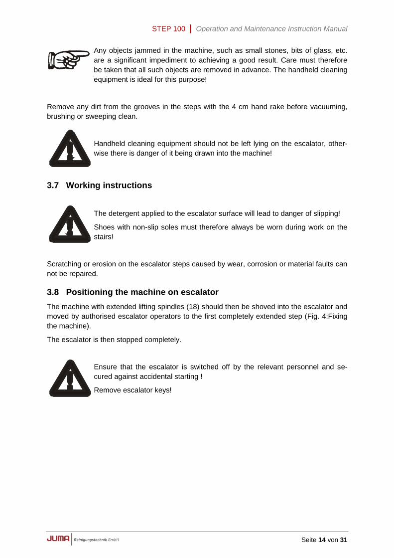
3.8 Positioning the machine on escalator
The machine with extended lifting spindles (18) should then be shoved into the escalator and
moved by authorised escalator operators to the first completely extended step (Fig. 4:Fixing
the machine).
The escalator is then stopped completely.
Ensure that the escalator is switched off by the relevant personnel and se-
cured against accidental starting !
Remove escalator keys!
STEP 100 | Operation and Maintenance Instruction Manual
Seite 15 von 31
Figure 4 Fixing the machine
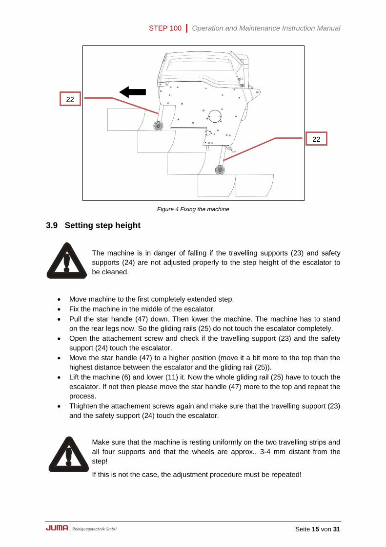
3.9 Setting step height
The machine is in danger of falling if the travelling supports (23) and safety
supports (24) are not adjusted properly to the step height of the escalator to
be cleaned.
Move machine to the first completely extended step.
Fix the machine in the middle of the escalator.
Pull the star handle (47) down. Then lower the machine. The machine has to stand
on the rear legs now. So the gliding rails (25) do not touch the escalator completely.
Open the attachement screw and check if the travelling support (23) and the safety
support (24) touch the escalator.
Move the star handle (47) to a higher position (move it a bit more to the top than the
highest distance between the escalator and the gliding rail (25)).
Lift the machine (6) and lower (11) it. Now the whole gliding rail (25) have to touch the
escalator. If not then please move the star handle (47) more to the top and repeat the
process.
Thighten the attachement screws again and make sure that the travelling support (23)
and the safety support (24) touch the escalator.
Make sure that the machine is resting uniformly on the two travelling strips and
all four supports and that the wheels are approx.. 3-4 mm distant from the
step!
If this is not the case, the adjustment procedure must be repeated!
22
22
STEP 100 | Operation and Maintenance Instruction Manual
Seite 16 von 31
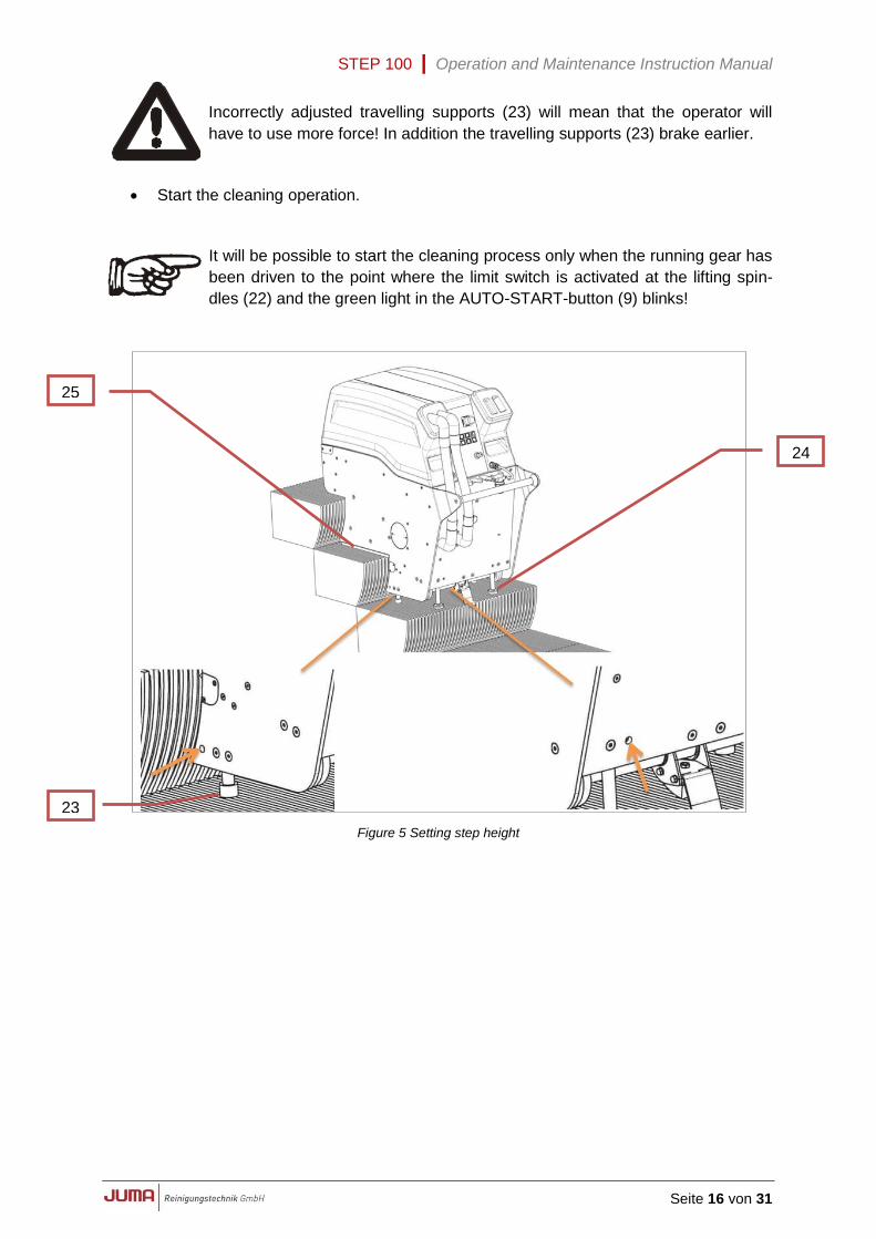
Incorrectly adjusted travelling supports (23) will mean that the operator will
have to use more force! In addition the travelling supports (23) brake earlier.
Start the cleaning operation.
It will be possible to start the cleaning process only when the running gear has
been driven to the point where the limit switch is activated at the lifting spin-
dles (22) and the green light in the AUTO-START-button (9) blinks!
Figure 5 Setting step height
23
24
25
STEP 100 | Operation and Maintenance Instruction Manual
Seite 17 von 31
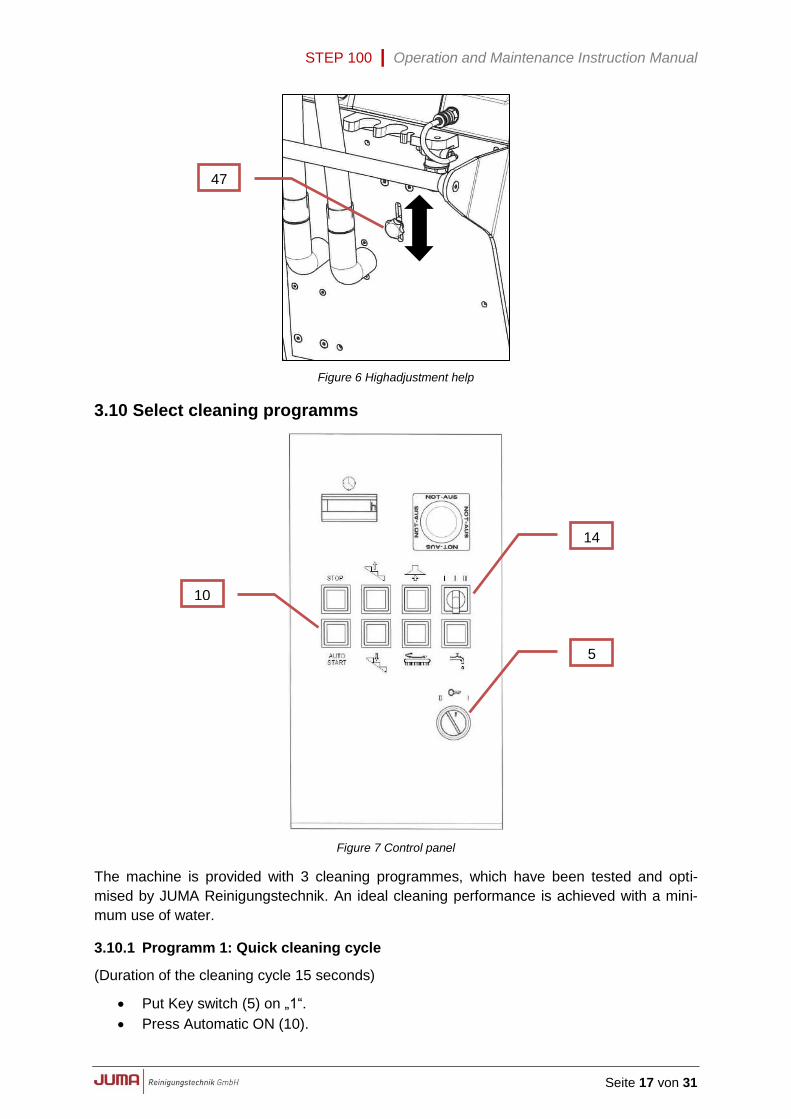
Figure 6 Highadjustment help
3.10 Select cleaning programms
Figure 7 Control panel
The machine is provided with 3 cleaning programmes, which have been tested and opti-
mised by JUMA Reinigungstechnik. An ideal cleaning performance is achieved with a mini-
mum use of water.
3.10.1 Programm 1: Quick cleaning cycle
(Duration of the cleaning cycle 15 seconds)
Put Key switch (5) on „1“.
Press Automatic ON (10).
14
10
5
47
STEP 100 | Operation and Maintenance Instruction Manual
Seite 18 von 31
3.10.2 Programm 2: Maintenance cleaning cycle
(Duration of the cleaning cycle 27 seconds)
Put Key switch (5) on „1“.
Choose program „2“ with the mode switch (14).
Press Automatic ON (10).
Switch from program 2 to program 1 during the cleaning cyrcle: Same process as
program 2.
Switch from program 1 to program 2 during the cleaning cyrcle: Same process as
program 1.
3.10.3 Programm 3: Intensive cleaning cycle
(Duration of the cleaning cycle 39 seconds)
Put Key switch (5) on „1“.
Choose program „3“ with the mode switch (14).
Press Automatic ON (10).
Switch from program 3 to program 2 during the cleaning cyrcle: Same process as
program 3.
Switch from program 2 to program 3 during the cleaning cyrcle: Same process as
program 2.
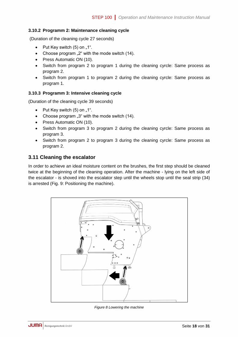
3.11 Cleaning the escalator
In order to achieve an ideal moisture content on the brushes, the first step should be cleaned
twice at the beginning of the cleaning operation. After the machine - lying on the left side of
the escalator - is shoved into the escalator step until the wheels stop until the seal strip (34)
is arrested (Fig. 9: Positioning the machine).
Figure 8 Lowering the machine
STEP 100 | Operation and Maintenance Instruction Manual
Seite 19 von 31
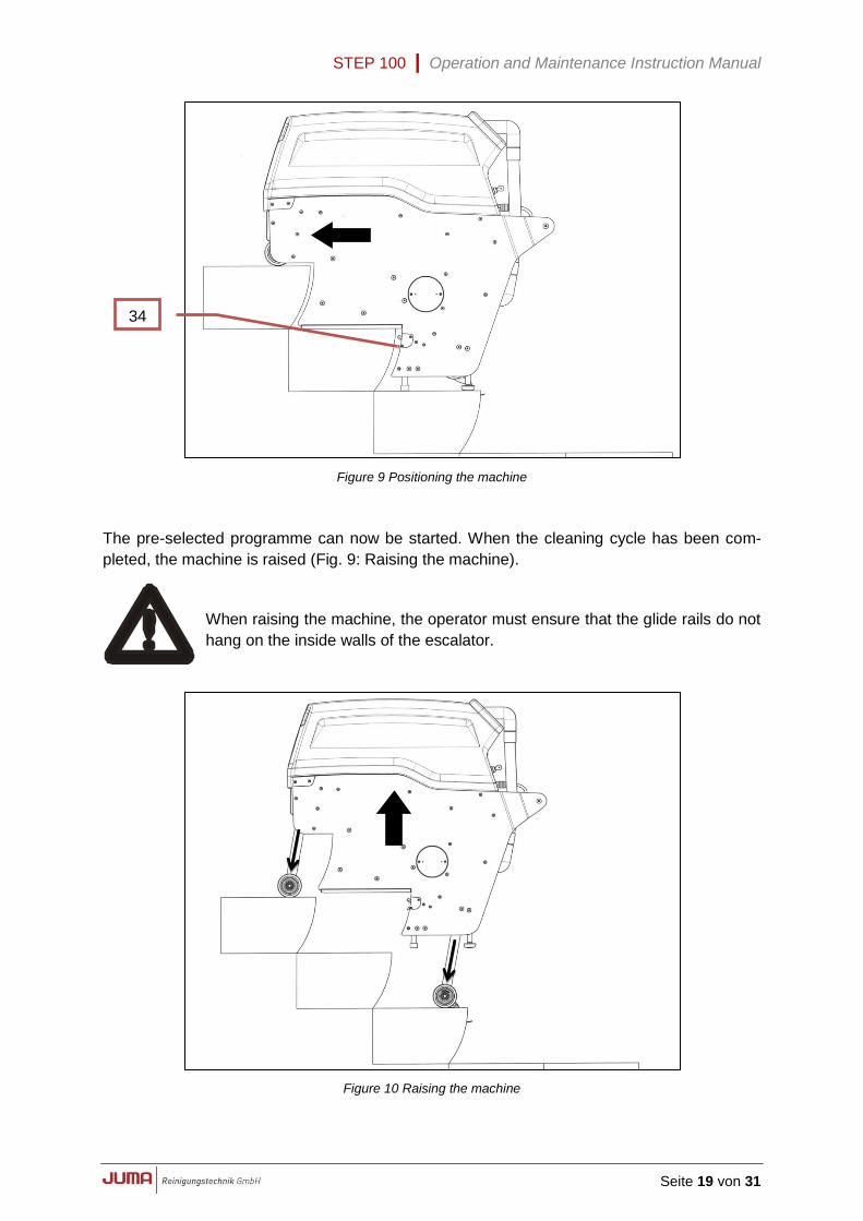
Figure 9 Positioning the machine
The pre-selected programme can now be started. When the cleaning cycle has been com-
pleted, the machine is raised (Fig. 9: Raising the machine).
When raising the machine, the operator must ensure that the glide rails do not
hang on the inside walls of the escalator.
Figure 10 Raising the machine
34
STEP 100 | Operation and Maintenance Instruction Manual
Seite 20 von 31
The machine is then shoved forward again until the wheels stop on the next highest step
(Fig. 4: Fixing the machine), and then lowered again. The machine can now be shoved on
the glide rails into the new working position (Fig. 9: Positioning the machine).
Repetition of the procedure described above will allow the escalator to be cleaned from the
bottom to the top completely-extended step.
Always ensure that the power cable is disconnected and wound up before the
escalator is started again to avoid accidents!
The switched-off and lowered machine is then driven downwards with the escalator to the
position of the last extended step.
After the cable has been connected once more, the procedure described above can be start-
ed anew and the escalator cleaned again up to the top completely extended step. After the
machine has been run from the lower to the highest completely extended step, one side of
the escalator will have been cleaned.
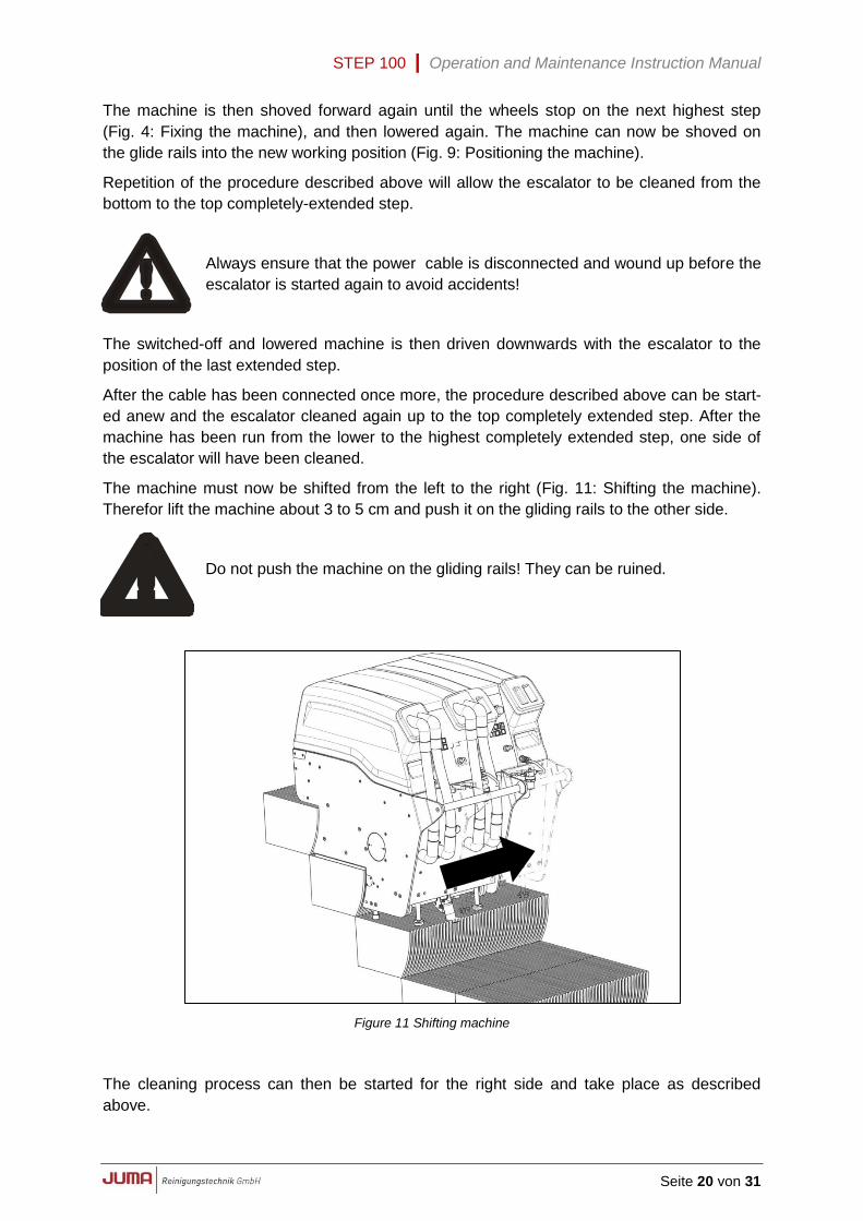
The machine must now be shifted from the left to the right (Fig. 11: Shifting the machine).
Therefor lift the machine about 3 to 5 cm and push it on the gliding rails to the other side.
Do not push the machine on the gliding rails! They can be ruined.
Figure 11 Shifting machine
The cleaning process can then be started for the right side and take place as described
above.
STEP 100 | Operation and Maintenance Instruction Manual
Seite 21 von 31
3.12 Subsequent cleaning
Manual cleaning equipment has been developed by JUMA Reinigungstechnik GmbH by
means of comprehensive practical tests.
With this equipment, any subsequent cleaning that may become necessary, such as major
soiling on the edges and the joining areas between two steps, can be carried out easily.
The manual cleaning equipment manufactured by JUMA Reinigungstechnik
GmbH is particularly suitable for minor subsequent cleaning.
3.13 Refilling with fresh water
The operator must carry out regular checks at the transparent feeder tube for fresh water
(27) to ensure that the machine is receiving a supply of detergent solution. If bubbles appear
in the tube or if no liquid can be seen, the fresh-water tank is empty and must be refilled.
Let the machine stand in the lowered position on the escalator and fill fresh water along with
cleaning agent according to instructions in Chapter 3.3.
When the fresh-water tank is being filled it is essential that the dirty-water tank
is emptied.
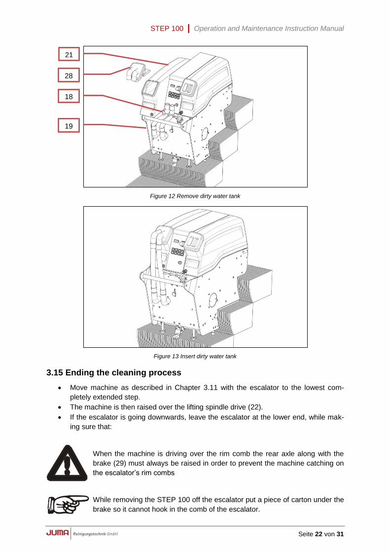
3.14 Emptying the dirty-water tanks
(see Fig. 12 Remove dirty water tank and Fig. 13: Insert dirty water tank)
Set key switch (5) to "0" position.
Draw the dirty-water tank (21) forward and set down onto the side plate (19).
Put in the suction tubes into the hose bracket (18)
Remove tank lid (28) and put it to the side.
Grip tank on the carrying-troughs and dispose of dirty water according to the relevant
environment regulations.
All valid regulations regarding waste water must be strictly observed when the
dirty water is being dumped!
Place dirty-water tank (21) onto the side plate (19) and insertion area.
Replace tank cover (28).
Adapt the suction tubes (take care of the coorect fitting; the tubes have to be adapted
so that the do not cross each other!)
Shove in tank (21) and check secure mounting.
Set key switch (5) to position "1".
Start suction with START/STOP key (9).
Check fitting of tank cover (28)!
Switch off suction with START/STOP key (9).
The work can now be continued.
STEP 100 | Operation and Maintenance Instruction Manual
Seite 22 von 31
Figure 12 Remove dirty water tank
Figure 13 Insert dirty water tank
3.15 Ending the cleaning process
Move machine as described in Chapter 3.11 with the escalator to the lowest com-
pletely extended step.
The machine is then raised over the lifting spindle drive (22).
If the escalator is going downwards, leave the escalator at the lower end, while mak-
ing sure that:
When the machine is driving over the rim comb the rear axle along with the
brake (29) must always be raised in order to prevent the machine catching on
the escalator’s rim combs
While removing the STEP 100 off the escalator put a piece of carton under the
brake so it cannot hook in the comb of the escalator.
21
28
19
18
STEP 100 | Operation and Maintenance Instruction Manual
Seite 23 von 31
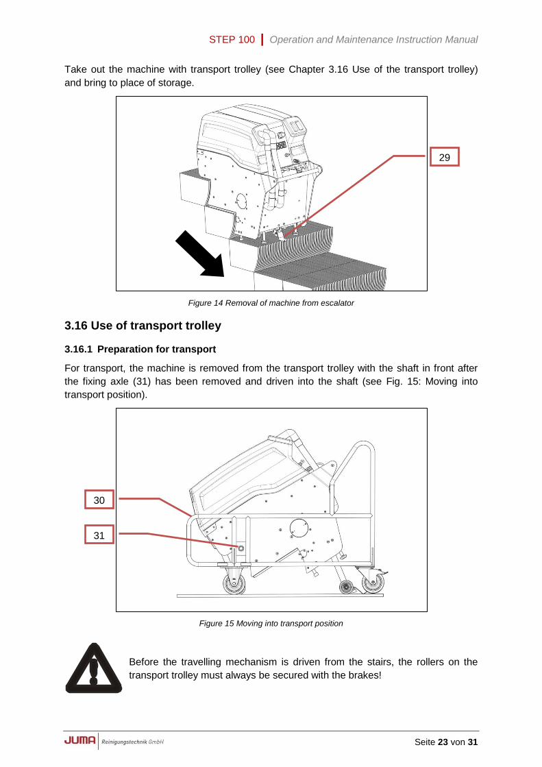
Take out the machine with transport trolley (see Chapter 3.16 Use of the transport trolley)
and bring to place of storage.
Figure 14 Removal of machine from escalator
3.16 Use of transport trolley
3.16.1 Preparation for transport
For transport, the machine is removed from the transport trolley with the shaft in front after
the fixing axle (31) has been removed and driven into the shaft (see Fig. 15: Moving into
transport position).
Figure 15 Moving into transport position
Before the travelling mechanism is driven from the stairs, the rollers on the
transport trolley must always be secured with the brakes!
29
30
31
STEP 100 | Operation and Maintenance Instruction Manual
Seite 24 von 31
After the fixing axle (31) has been inserted and secured, the travelling mechanism can be
drawn in and the machine thus placed on the transport trolley.
The fixing axle (31) must be secured against slipping out by means of the
supplied permanent cotter pin !
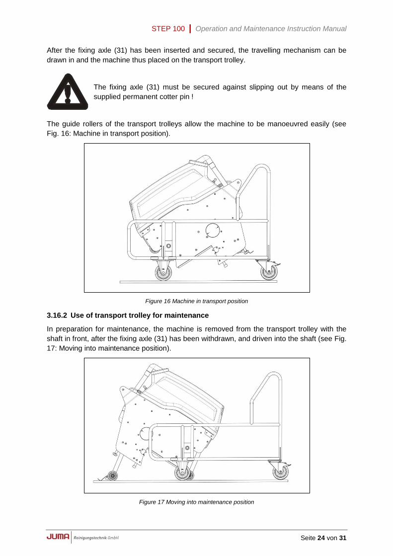
The guide rollers of the transport trolleys allow the machine to be manoeuvred easily (see
Fig. 16: Machine in transport position).
Figure 16 Machine in transport position
3.16.2 Use of transport trolley for maintenance
In preparation for maintenance, the machine is removed from the transport trolley with the
shaft in front, after the fixing axle (31) has been withdrawn, and driven into the shaft (see Fig.
17: Moving into maintenance position).
Figure 17 Moving into maintenance position
STEP 100 | Operation and Maintenance Instruction Manual
Seite 25 von 31
Before the travelling gear is drawn in, the roller of the transport trolley must
always be secured with the brakes!
After the fixing axle (31) has been inserted and secured again, the travelling gear can be
drawn in to about a third its length and the machine then swung into the maintenance posi-
tion on the trolley.
The fixing axle (31) must be secured against slipping out by means of the
supplied permanent cotter pin!
Before turning the machine remove both tanks (17; 21) and their covers (20;
28). Otherwise they can be damaged!
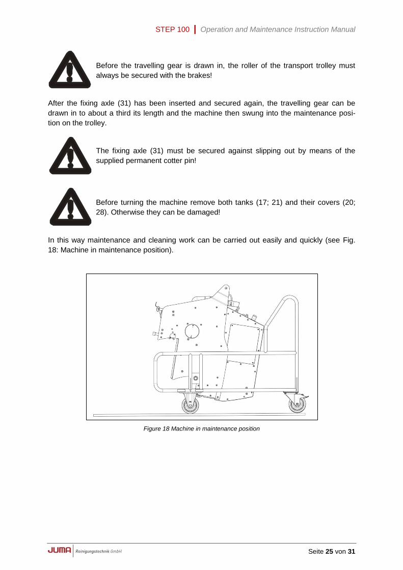
In this way maintenance and cleaning work can be carried out easily and quickly (see Fig.
18: Machine in maintenance position).
Figure 18 Machine in maintenance position
STEP 100 | Operation and Maintenance Instruction Manual
Seite 26 von 31
4 Maintenance / Care
4.1 Safety measures during cleaning and maintenance of the machine
Before any maintenance or cleaning work is carried out, the machine must be sepa-
rated from the mains with the main switch being set to "0“ and the mains plug discon-
nected. This will prevent accidents caused by electrical voltage or moving parts.
During cleaning or maintenance work on the machine, when parts are being replaced
or new equipment fitted for a new function, care must be taken that the machine can
not accidentally start, roll or turn over and that no parts can fall down or flap closed.
If the operator has any questions or doubts regarding safety, he must request advice from
the manufacturer or the relevant sales agent before starting the machine.
4.2 Daily care
Examine the power cable for any damage.
Always empty the dirty-water tank (21) following use and rinse thoroughly with water
Inspect brushes (1) and clean.
Rinse out suction basin (32).
Clean stripping brush (33).
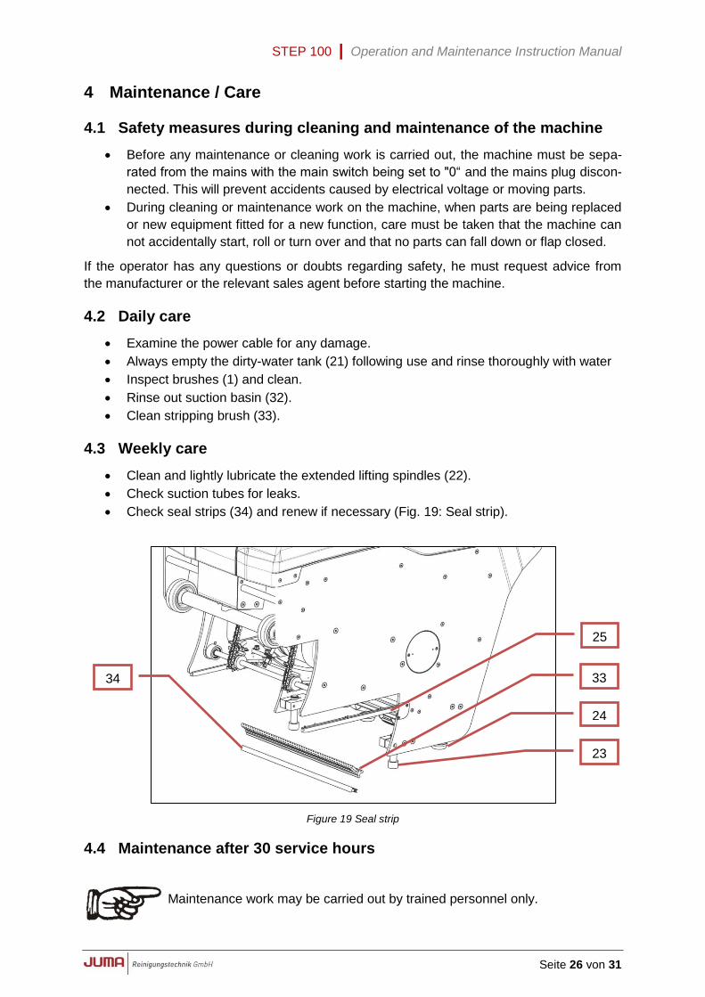
4.3 Weekly care
Clean and lightly lubricate the extended lifting spindles (22).
Check suction tubes for leaks.
Check seal strips (34) and renew if necessary (Fig. 19: Seal strip).
Figure 19 Seal strip
4.4 Maintenance after 30 service hours
Maintenance work may be carried out by trained personnel only.
33 34
25
24
23
STEP 100 | Operation and Maintenance Instruction Manual
Seite 27 von 31
Remove suction basin (32) and stripping brush (33) and rinse (Fig. 18: Seal strip)
Check chains (35) for correct tension and, if necessary, tighten with chain adjuster
44) (see Chapter 4.6.1 Tightening the chain and Fig. 20: Chain drive /Spraying noz-
zle).
Clean chains (35) and treat with a chain spray.
Check spray nozzles (36) and clean if necessary.
Check glide rails (25) on the right and the left. Replace if showing signs of wear (Fig.
19: Seal strip).
Check sliding elements of the step adjustment device (23 and 24). Replace in case of
wear.
Check seal strip (34) and renew if necessary (Fig. 18: Seal strip).
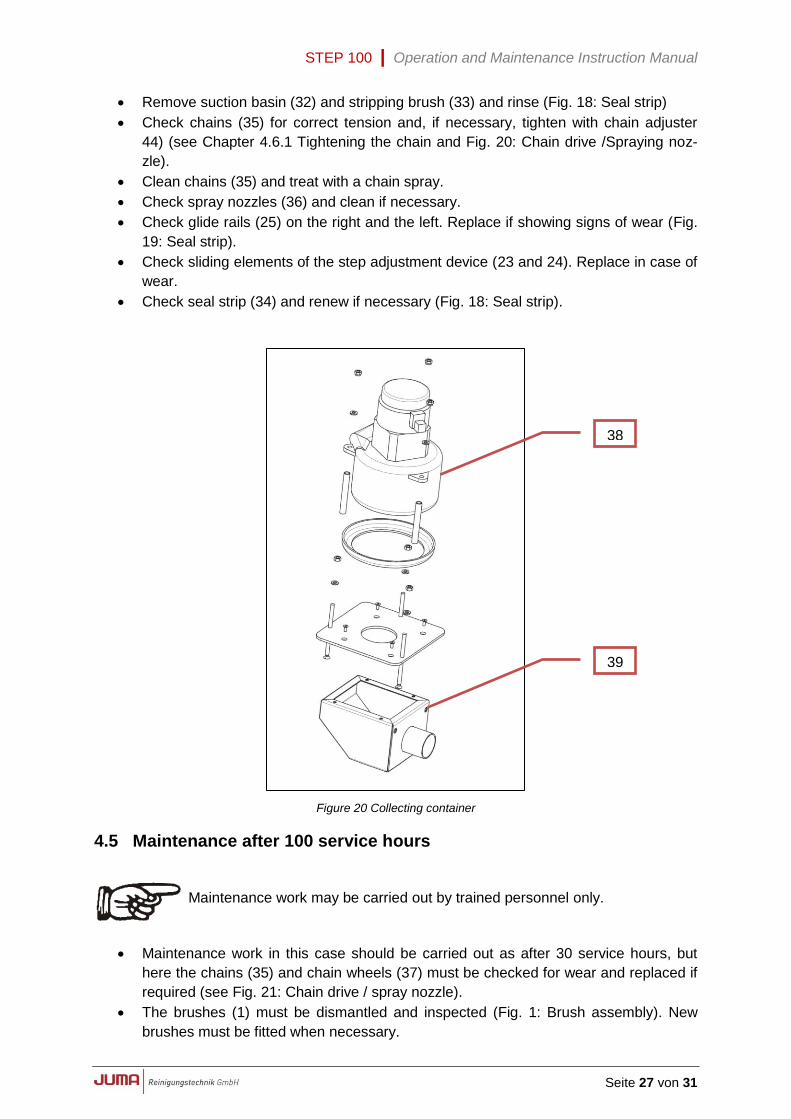
Figure 20 Collecting container
4.5 Maintenance after 100 service hours
Maintenance work may be carried out by trained personnel only.
Maintenance work in this case should be carried out as after 30 service hours, but
here the chains (35) and chain wheels (37) must be checked for wear and replaced if
required (see Fig. 21: Chain drive / spray nozzle).
The brushes (1) must be dismantled and inspected (Fig. 1: Brush assembly). New
brushes must be fitted when necessary.
38
39
STEP 100 | Operation and Maintenance Instruction Manual
Seite 28 von 31
Clean collecting container (39) under the suction device (38).
Check all electrical components.
4.6 Anumal maintenance
An electrically driven machine must be examined every year in accordance with VDE 702 or
some comparable international standards.
This examination must be carried out by a service technician trained by JUMA
Reinigungstechnik GmbH
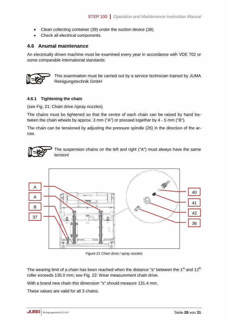
4.6.1 Tightening the chain
(see Fig. 21: Chain drive /spray nozzles)
The chains must be tightened so that the centre of each chain can be raised by hand be-
tween the chain wheels by approx. 3 mm ("A") or pressed together by 4 - 5 mm ("B").
The chain can be tensioned by adjusting the pressure spindle (26) in the direction of the ar-
row.
The suspension chains on the left and right ("A") must always have the same
tension!
Figure 21 Chain drive / spray nozzles
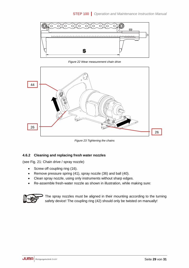
The wearing limit of a chain has been reached when the distance "s" between the 1st and 12th
roller exceeds 135.0 mm; see Fig. 22: Wear measurement chain drive.
With a brand new chain this dimension "s" should measure 131.4 mm.
These values are valid for all 3 chains.
A
A
B
37
40
41
36
42
STEP 100 | Operation and Maintenance Instruction Manual
Seite 29 von 31
Figure 22 Wear measurement chain drive
Figure 23 Tightening the chains
4.6.2 Cleaning and replacing fresh water nozzles
(see Fig. 21: Chain drive / spray nozzle)
Screw off coupling ring (16).
Remove pressure spring (41), spray nozzle (36) and ball (40).
Clean spray nozzle, using only instruments without sharp edges.
Re-assemble fresh-water nozzle as shown in illustration, while making sure:
The spray nozzles must be aligned in their mounting according to the turning
safety device! The coupling ring (42) should only be twisted on manually!
44
26
26
STEP 100 | Operation and Maintenance Instruction Manual
Seite 30 von 31
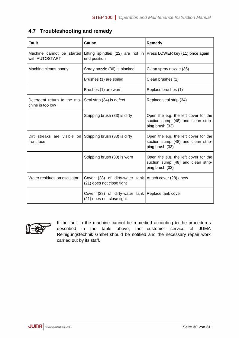
4.7 Troubleshooting and remedy
Fault Cause Remedy
Machine cannot be started
with AUTOSTART
Lifting spindles (22) are not in
end position
Press LOWER key (11) once again
Machine cleans poorly Spray nozzle (36) is blocked Clean spray nozzle (36)
Brushes (1) are soiled Clean brushes (1)
Brushes (1) are worn Replace brushes (1)
Detergent return to the ma-
chine is too low
Seal strip (34) is defect Replace seal strip (34)
Stripping brush (33) is dirty Open the e.g. the left cover for the
suction sump (48) and clean strip-
ping brush (33)
Dirt streaks are visible on
front face
Stripping brush (33) is dirty Open the e.g. the left cover for the
suction sump (48) and clean strip-
ping brush (33)
Stripping brush (33) is worn Open the e.g. the left cover for the
suction sump (48) and clean strip-
ping brush (33)
Water residues on escalator Cover (28) of dirty-water tank
(21) does not close tight
Attach cover (28) anew
Cover (28) of dirty-water tank
(21) does not close tight
Replace tank cover
If the fault in the machine cannot be remedied according to the procedures
described in the table above, the customer service of JUMA
Reinigungstechnik GmbH should be notified and the necessary repair work
carried out by its staff.
STEP 100 | Operation and Maintenance Instruction Manual
Seite 31 von 31
5 Notizen