Embed Size (px)
Citation preview
Offline Parameter Estimation of Permanent MagnetSynchronous Machines by means of LS
OptimizationAndras Zentai
Shizuoka UniversityHamamatsu, Japan
Tamas DabocziBudapest University of
Technology and EconomicsBudapest, Hungary
Abstract—Industrial applications, especially automotive onesshould be robust and cheap. Both properties can be improvedby using model based state estimation. Sensor cost can be reducedif some signal values are calculated from the other, alreadymea-sured signals or the robustness of the system can be increased bysupervising the sensors by calculating their measurement valueout of the existing signal values. Robustness and redundancy isextremely important considering drive-by-wire technology, wherethe physical connection between the steering wheel and thewheels of the vehicle is omitted. This paper reports advancesin permanent magnet synchronous machine model identification.By measuring machine input voltages, output currents speedandusing the least squares optimization method, internal parametersof the machine can be estimated. In the identification stage,themodel excitation signals are the current values and the speedof the machine and the response signals are the input voltages.After having a properly identified model, the output currentsand electrical torque of the machine can be calculated knowingthe input voltages and the speed of the machine. Those currentsensors can be either eliminated or supervised by the model basedredundant information.
Keywords: permanent magnet synchronous machine, drive-by-wire, model identification, least squares method
I. I NTRODUCTION
Permanent Magnet Synchronous Machines (PMSM) areused in a wide variety of industrial applications. Because oftheir compact design and high efficiency, they are preferredin Electric Power Assisted Steering (EPAS) systems. Steeringsystems are safety-critical applications; therefore, they haveto be designed by maximizing safety, redundancy and re-liability. Automotive environment postulates further specialrequirements for EPAS applications, as e.g., the usage ofunregulated and usually low voltage levels and providing hightorque at high speeds with small size and high efficiency. Thesystem cost also plays an important role in automobile systemdesign because in high volume production every additionalpart may dramatically increase the overall cost. Designingcheap and reliable systems forces the engineers to build asfew sensors as possible into the system and extract as muchinformation as possible from the output of the sensors. Onepossible realization of this design principle is to implementredundant functions, which is required for safety checking,
without using redundant sensors, but rather using the availablesensor data and model based simulations to calculate theappropriate value. In this paper, this technique is used inthe following way: the machine input voltage signals andmachine speed are measured, and using a machine modelwith properly identified parameters, the machine currents areestimated. The precision of the model-based estimation highlydepends on the model parameters. Therefore, it is necessaryto determine the model parameters precisely. In this paper,theauthors are introducing the identification problem of PMSMand solving it using the least squares (LS) method [1]–[3]. Thesame problem is solved by the authors using other techniquesas it can bee seen in [4], [5]. Other authors have alreadypresented parameter identification methods [6], [7] for PMSMdrives, but these articles deal only with the identificationofthe mechanical parameters of the machine, considering theelectrical parameters to be known and constant.
The main goal of this paper is to present a method to iden-tify the electrical parameters. There were other publications onthis topic [8] but, in that paper, the machine inductivity wasneglected. That consideration results in a model which can beused only at slow machine speed. However electrical machinesused in EPAS applications are driven at high speeds and havea nonnegligible inductivity parameter. In [9], an identificationof stepper motor model was performed using LS method.Although [9] deals with a different machine type, that machinecan be described using the same differential equations. In [9],the author used a machine model where the inductivity is nota function of the rotor angle. However, in many applications,it is essential to have rotor angle dependent inductivity and itis especially needed for reluctance variationbased sensorlessrotor position detection algorithms [10]. Using this algorithm,it is neccessary to have 10-30% difference between the lowestand the highest inductivity of the machine. In this paper, amore advanced motor model will be presented introducingrotor angle dependent inductivity. This model is describedin a reference frame rotating synchronously with the rotor(d,q model) (2) and Fig. 1. The parameters of this motormodel will be identified using LS method. PMSM modelparameter estimation will be described in the following order:
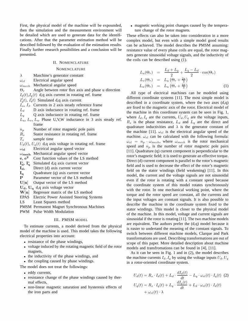
First, the physical model of the machine will be expounded,then the simulation and the measurement environment willbe detailed which are used to generate data for the identifi-cations. After that the parameter estimation method will bedescribed followed by the evaluation of the estimation results.Finally further research possibilities and a conclusion will bepresented.
II. N OMENCLATURE
NOMENCLATURE
λ Maschine’s generator constantωel Electrical angular speedωmech Mechanical angular speedΘr Angle between rotor flux axis and phase u directionId(t),Iq(t) d,q axis current in rotating ref. frameI(dt), I
(qt) Simulated d,q axis current
Iα, Iβ Currents in 2 axis steady reference frameLd D axis inductance in rotating ref. frameLq Q axis inductance in rotating ref. frameLu, Lv, Lw Phase U,V,W inductance in 3 axis steady ref.
framenp Number of rotor magnetic pole pairsRs Stator resistance in rotating ref. frameTs sample timeUd(t), Uq(t) d,q axis voltage in rotating ref. frameωel Electrical angular speed vectorωmech Mechanical angular speed vectore, e
2 Cost function values of the LS methodI∗
d, I∗
q Simulated d,q axis current vectorId, Direct (d) axis current vectorIq Quadrature (q) axis current vectorP Parameter vector of the LS methodU[n] Output vector of the LS methodUd, Uq d,q axis voltage vectorW[n] Regressor matrix of the LS methodEPAS Electric Power Assisted Steering SystemsLS Least Squares methodPMSM Permanent Magnet Synchronous MachinesPWM Pulse Width Modulation
III. PMSM MODEL
To estimate currents, a model derived from the physicalmodel of the machine is used. This model takes the followingelectrical properties into account:
• resistance of the phase windings,• voltage induced by the rotating magnetic field of the rotor
magnets,• the inductivity of the phase windings, and• the coupling caused by phase windings.
The model does not treat the followings:
• eddy currents,• resistance change of the phase windings caused by ther-
mal effects,• non-linear magnetic saturation and hysteresis effects of
the iron parts and
• magnetic working point changes caused by the tempera-ture change of the rotor magnets.
These effects can also be taken into consideration in a morecomplex model, but even with a simple model good resultscan be achieved. The model describes the PMSM assuming:resistance value of every phase coils are equal, the rotor mag-nets generate sinusoidal voltage signals, and the inductivity ofthe coils can be described using (1).
Lu(Θr) =Ld + Lq
2+
Lq − Ld
2· cos(Θr)
Lv(Θr) = Lu
(
Θr + 2π3
)
Lw(Θr) = Lu
(
Θr + 4π3
)
(1)
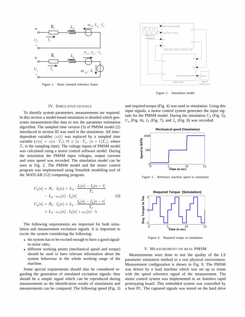
All type of electrical machines can be modeled usingdifferent coordinate systems [11]. The most simple model isdescribed in a coordinate system, where the two axes (d,q)are fixed to the magnetic axis of the rotor. Electrical model ofthe machine in this coordinate system can be seen in Fig. 1,whereId, Iq are the currents,Ud, Uq are the voltage inputs,Rs is the phase resistance,Ld and Lq are the direct andquadrature inductivities andλ is the generator constant ofthe machine [11].ωel is the electrical angular speed of themachine.ωel can be calculated with the following formula:ωel = np · ωmech, where ωmech is the rotor mechanicalspeed andnp is the number of rotor magnetic pole pairs[11]. Quadrature (q) current component is perpendicular totherotor’s magnetic field; it is used to generate an effective torque.Direct (d) current component is parallel to the rotor’s magneticfield and is used to decrease the effect of the rotor’s magneticfield on the stator windings (field weakening) [11]. In thismodel, the current and the voltage signals are not sinusoidaleven if the rotor is rotating with a constant speed becausethe coordinate system of this model rotates synchronouslywith the rotor. In one mechanical working point, where thetorque and the rotor speed are constant, all the currents andthe input voltages are constant signals. It is also possibletodescribe the machine in the coordinate system fixed to thestator windings. This model is closer to the physical modelof the machine. In this model, voltage and current signals aresinusoidal if the rotor is rotating [11]. The two machine modelsare equivalent. The authors prefer the (d,q) model because itis easier to undertand the meaning of the constant signals. Toswitch between different machine models, Clarque and Parktransformations are used. Describing transformations areout ofscope of this paper. More detailed description about machinemodels and transfromations can be found in [4], [11].
As it can be seen in Fig. 1 and in (2), the model describesthe machine currentsId, Iq by using the voltage inputsUd, Uq
in a rotor-oriented coordinate system.
Ud(t) = Rs · Id(t) + Ld ·dId(t)
dt− Lq · ωel(t) · Iq(t) (2)
Uq(t) = Rs · Iq(t) + Lq ·dIq(t)
dt+ Ld · ωel(t) · Id(t)
+ ωel(t) · λ
Ud
+
-
Rs
+
-
Id
UqIq l×
e lω
Rs
de lω IL d ××
qq IL ××el
ω
qL
dL
Figure 1. Rotor oriented reference frame
IV. SIMULATED SIGNALS
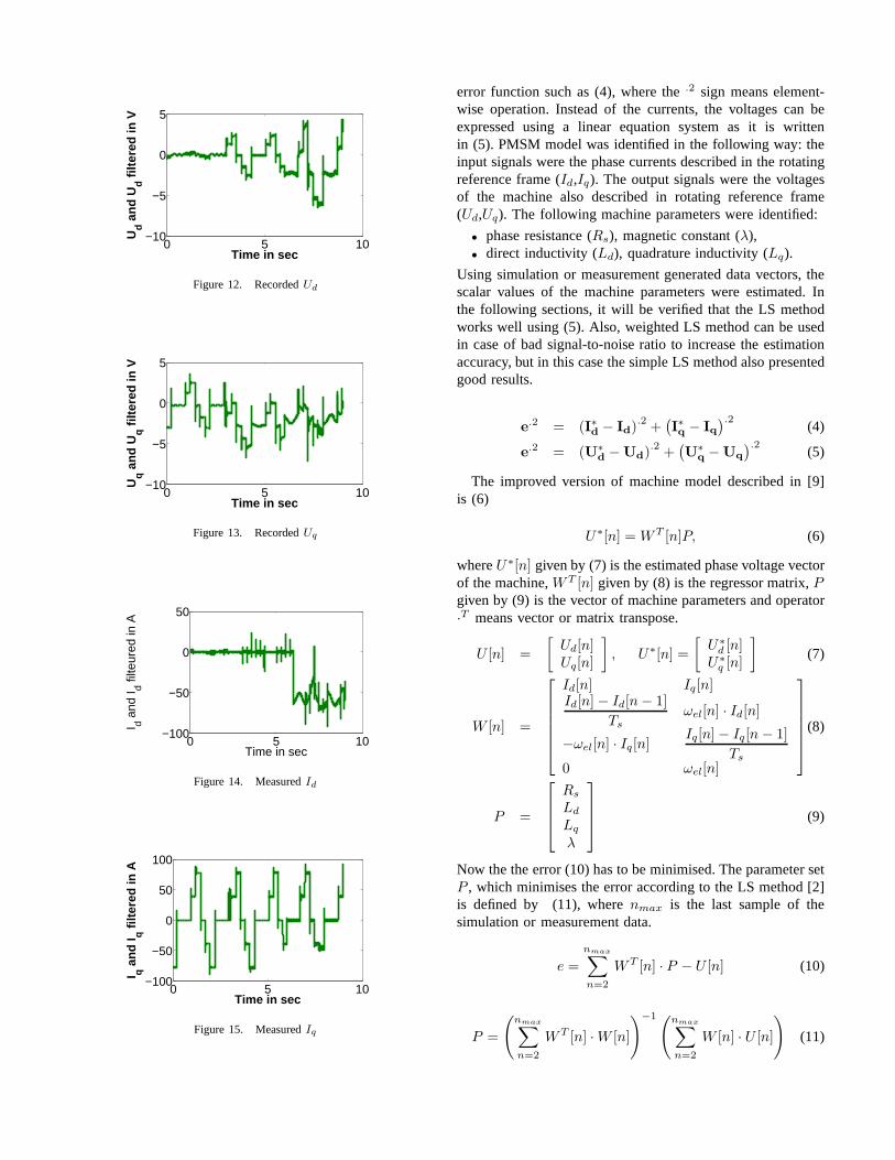
To identify system parameters, measurements are required.In this section a model-based simulation is detailed which gen-erates measurement-like data to test the parameter estimationalgorithm. The sampled time version (3) of PMSM model (2)introduced in section III was used in the simulation. All time-dependent variables(x(t) was replaced by a sampled timevariable (x[n] = x(n · Ts), ∀t ∈ [n · Ts, (n + 1)Ts), whereTs is the sampling time). The voltage inputs of PMSM modelwas calculated using a motor control software model. Duringthe simulation the PMSM input voltages, output currentsand rotor speed was recorded. The simulation model can beseen in Fig. 2. The PMSM model and the motor controlprogram was implemented using Simulink modelling tool ofthe MATLAB [12] computing program.
Ud[n] = Rs · Id[n] + Ld ·Id[n] − Id[n − 1]
Ts
− Lq · ωel[n] · Iq[n] (3)
Uq[n] = Rs · Iq[n] + Lq ·Iq[n] − Iq [n − 1]
Ts
+ Ld · ωel[n] · Id[n] + ωel[n] · λ
The following requirements are important for both simu-lation and measurement excitation signals. It is importanttoexcite the system considering the following:
• ths system has to be excited enough to have a good signal-to-noise ratio,
• different working points (mechanical speed and torque)should be used to have relevant information about thesystem behaviour in the whole working range of themachine.
Some special requirements should also be considered re-garding the generation of simulated excitation signals: theyshould be a simple signal which can be reproduced duringmeasurements so the identification results of simulations andmeasurements can be compared. The following speed (Fig. 3)
discrete motor control system
Machine_speed_RPM
Required Torque
Iq
Id
Uq
Ud
Speed
generator
Speed
Repeating
Sequence
PMSM model
Ud
Uq
Machine_speed_RPM
Id
Iq
Figure 2. Simulation model
and required torque (Fig. 4) was used in simulation. Using thisinput signals, a motor control system generates the input sig-nals for the PMSM model. During the simulationUd (Fig. 5),Uq (Fig. 6), Id (Fig. 7), andIq (Fig. 8) was recorded.
0 5 10 150
500
1000
Mechanical speed (Simulation)
Time in secs
Spe
ed in
RP
M
Figure 3. Reference machine speed in simulation
0 5 10 15−5
0
5
Required Torque (Simulation)
Time in secs
Req
. Tor
que
in N
m
Figure 4. Required torque in simulation
V. M EASUREMENT ON REALPMSM
Measurements were done to test the quality of the LSparameter estimation method in a real physical environment.Measurement configuration is shown in Fig. 9. The PMSMwas driven by a load machine which was set up to rotatewith the speed reference signal of the measurement. Themotor control system was implemented in an Autobox rapidprototyping board. This embedded system was controlled bya host PC. The captured signals was stored on the hard drive

0 5 10 15−4
−2
0
2
4
Time in sec
Ud in
Vol
ts
Figure 5. SimulatedUd
0 5 10 15−10
−5
0
5
10
Time in sec
Uq in
Vol
ts
Figure 6. SimulatedUq
0 5 10 15−50
0
50
Time in sec
I d in A
mpe
rs
Figure 7. SimulatedId
0 5 10 15−100
−50
0
50
100
Time in sec
I q in A
mpe
rs
Figure 8. SimulatedIq
of the PC. The pulse width modulation (PWM) signals –generated by the Autobox – are processed by an inverter,which applies the voltage signals to the PMSM. The following
Figure 9. Measurement configuration
speed (Fig. 10) and required torque (Fig. 11) was used duringmeasurement. The following signalsUd (Fig. 12),Uq (Fig. 13),Id (Fig. 14), andIq (Fig. 15) were recorded.
0 2 4 6 8
200
400
600
800
1000
Time in sec
ωel
in R
PM
Mechanical speed (Measurement)
Figure 10. Reference machine speed during measurement
0 2 4 6 8−5
0
5
Required Torque (Measurement)
Time in secs
Req
. Tor
que
in N
m
Figure 11. Required torque during measurement
VI. M ODEL PARAMETER ESTIMATION
The goal of the optimization was to minimize the differ-ence between the model-based (I∗d (t),I∗q (t)) and the measured(Id(t),Iq(t)) machine currents. Unfortunately, the currents cannot be written using a linear combination of the parameters,so the LS method can not be used directly to optimise an
0 5 10−10
−5
0
5
Time in sec
Ud a
nd
Ud f
ilter
ed in
V
Figure 12. RecordedUd
0 5 10−10
−5
0
5
Time in sec
Uq a
nd
Uq f
ilter
ed in
V
Figure 13. RecordedUq
0 5 10−100
−50
0
50
Time in sec
I d and
I d filte
ured
in A
Figure 14. MeasuredId
0 5 10−100
−50
0
50
100
Time in sec
I q a
nd
I q f
ilter
ed in
A
Figure 15. MeasuredIq
error function such as (4), where the.2 sign means element-wise operation. Instead of the currents, the voltages can beexpressed using a linear equation system as it is writtenin (5). PMSM model was identified in the following way: theinput signals were the phase currents described in the rotatingreference frame (Id,Iq). The output signals were the voltagesof the machine also described in rotating reference frame(Ud,Uq). The following machine parameters were identified:
• phase resistance (Rs), magnetic constant (λ),• direct inductivity (Ld), quadrature inductivity (Lq).
Using simulation or measurement generated data vectors, thescalar values of the machine parameters were estimated. Inthe following sections, it will be verified that the LS methodworks well using (5). Also, weighted LS method can be usedin case of bad signal-to-noise ratio to increase the estimationaccuracy, but in this case the simple LS method also presentedgood results.
e.2 = (I∗d − Id)
.2+(
I∗
q − Iq
).2(4)
e.2 = (U∗
d − Ud).2
+(
U∗
q − Uq
).2(5)
The improved version of machine model described in [9]is (6)
U∗[n] = WT [n]P, (6)
whereU∗[n] given by (7) is the estimated phase voltage vectorof the machine,WT [n] given by (8) is the regressor matrix,P
given by (9) is the vector of machine parameters and operator·T means vector or matrix transpose.
U [n] =
[
Ud[n]Uq[n]
]
, U∗[n] =
[
U∗
d [n]U∗
q [n]
]
(7)
W [n] =
Id[n] Iq[n]Id[n] − Id[n − 1]
Ts
ωel[n] · Id[n]
−ωel[n] · Iq[n]Iq[n] − Iq[n − 1]
Ts
0 ωel[n]
(8)
P =
Rs
Ld
Lq
λ
(9)
Now the the error (10) has to be minimised. The parameter setP , which minimises the error according to the LS method [2]is defined by (11), wherenmax is the last sample of thesimulation or measurement data.
e =
nmax∑
n=2
WT [n] · P − U [n] (10)
P =
(
nmax∑
n=2
WT [n] · W [n]
)
−1(nmax∑
n=2
W [n] · U [n]
)
(11)
Table IREAL AND ESTIMATED VALUES OF PARAMETERS
Rs in Ω Ld in µH Lq in µH λ in A/sec
Real val. 0.037500 115.00 125.00 0.010500
Est. val.
LS method 0.037500 115.00 124.99 0.010500
VII. E STIMATION RESULTS OF SIMULATED INPUT SIGNALS
In this section, the quality of the LS parameter estimationis evaluated using data files generated by simulation model.To validate the parameter estimation algorithm, numerousestimations are made using different data and random initialparameters. In Table I, the estimated parameter values usingLS method can be compared with the real values used forgenerating the simulation data.
VIII. E STIMATION RESULTS OF MEASURED INPUT
SIGNALS
In this section, the quality of the LS parameter estimationis evaluated using measurement data files. After successfulparameter estimation, the machine currents were estimatedusing the machine model. The measured and the estimatedcurrents can be seen in Fig. 16 and in Fig. 17. The figuresdemonstrate that the estimation method performs well.
0 2 4 6 8−100
−50
0
50
Measured and estimated Id current
Time in sec
Cu
rren
t in
A
Measured Id
Estimated Id
Figure 16. Measured and estimatedId currents
0 2 4 6 8−100
0
100
Measured and estimated Iq current
Time in sec
Cu
rren
t in
A
Estimated Iq
Measured Iq
Figure 17. Measured and estimatedIq currents
IX. CONCLUSION AND FURTHER RESEARCH PLAN
The main goal of the research was to identify a PMSMmodel. If the model based current estimations are reliableenough to replace the current sensor information, then the
machine can be controlled and machine torque can be esti-mated without properly working current measurement sensors.A model has been presented which resulted in good currentestimation. In this paper, an LS method was shown, whichis suitable for offline machine parameter estimation. Thepresented method works well both on simulation and on mea-surement collected data. For further development an on-line,real time machine parameter estimation can be investigated.Using on-line identification motor health monitoring can beimplemented.
X. ACKNOWLEDGMENT
Financial support of SUZUKI Foundation is appreciated.The authors would like to thank Dr. Hitoshi Katayama foradopting this topic into his laboratory. The authors wouldlike to thank ThyssenKrupp Research Institute Budapest forproviding measurement equipment. The authors would like tothank Vandy M. Paul for vetting this document.
REFERENCES
[1] A. van der Bos,Parameter estimation for scientists and engineers.Hoboken, New Jersey, USA: John Wiley & Sons, Inc., 2007.
[2] K. J. Astrom and B. Wittenmark,Adaptive Control. Boston, MA, USA:Addison-Wesley Longman Publishing Co., Inc., 1994.
[3] L. Ljung, System Identification Theory for the User Second Edition.Upper Saddle River, New Jersey, USA: Prientice Hall Ptr, 1999.
[4] A. Zentai and T. Daboczi, “Model based torque estimation of perma-nent magnet synchronous machines,” inIEEE International Symposiumon Diagnostics for Electric Machines, Power Electronics and Drives,Krakow, Poland, Sept 6–8, 2007, pp. 178–181.
[5] ——, “Using multi dimensional grid to identify a permanent magnetsynchronous machine model,” 2008, will be published in SI International2008.
[6] R. B. Sepe and J. H. Lang, “Real-time adaptive control of the permanent-magnet synchronous motor,”IEEE TRANSACTIONS ON INDUSTRYAPPLICATIONS, vol. 27, no. 4, pp. 706–714, JULY/AUGUST 1991.
[7] ——, “Real-time observer-based (adaptive) control of the permanent-magnet synchronous motor without mechanical sensors,”IEEE TRANS-ACTIONS ON INDUSTRY APPLICATIONS, vol. 28, no. 6, pp. 1345–1352, NOVEMBER/DECEMBER 1992.
[8] K. R. Shouse and D. G. Taylor, “A digital self-tuning tracking controllerfor permanent-magnet synchronous motors,”IEEE Trans. on ControlSystems Technology, vol. 2, no. 4, pp. 412–422, Dec 1994.
[9] A. J. Blauch, M. Bodson, and J. Chiasson, “High-speed parameter esti-mation of steppor motors,”IEEE Trans. on Control Systems Technology,vol. 1, no. 4, pp. 270–279, Dec 1993.
[10] M. Schroedl and M. Lambeck, “Statistic properties of the INFORM-method in highly dynamics sensorless PM motor control applicationsdown to standstill,”European Power Electronics and Drives, vol. 13,no. 3, pp. 22–29, Mar. 2003.
[11] P. Vas,Sensorless Vector and Direct Torque Control. Oxford: OxfordUniversity Press, 1998.
[12] The Matworks, Inc., “MATLAB programming language,”2008, [accessed 15-October-2008]. [Online]. Available: http://www.mathworks.com/products/matlab/