Embed Size (px)
Citation preview

Februari 2002 ECN-I--02-002
OFFSHORE WIND FARMS
Analysis of Transport and Installation Costs
S.A. Herman

2 ECN-I--02-002
Abstract
A computer model that calculates the transport and installation costs of a wind farm has beencomposed and implemented in the OWECOP II model. The latter quantifies all costs ofimplementation of a wind farm, at a determined location on the Dutch Exclusive EconomicalZone. Transport and installation are a part of it. The computer model is an Excel workbookthat includes an input part, a database part and a calculation part.
Transport and installation costs have been derived based on known offshore techniques and theyare structured according to possible wind turbine assembly procedures. Besides the cost ofoffshore equipment, also an estimation of delays due to bad weather and the use of severalvessels simultaneously have been included. Other costs included are: Scour protection costs,costs of soil research, costs of electric cable installation and costs of removal of wind turbine /wind turbine components after their operational lifetime.
Chapters 2 and 3 of this report analyse the possible transport and installation techniques, basedon state-of-the-art offshore equipment. Wind turbine mass estimation is realised in chapter 4. Inchapters 5 to 6, the analysis of costs for respectively transport and installation is presented.Chapter 7 describes the cost model and its implementation in a spreadsheet. In chapter 8 someresults are presented and the influence of some parameters is investigated. The conclusions andrecommendations are presented in chapter 9.
The calculation of costs for transport and installation of offshore wind turbines as implementedin the OWECOP model, could be detailed by a deeper analysis of workable conditions(probability of work), and implementation of wind turbine sizes and dimensions related to thetransport and installation vessels.
Keywords
Offshore, wind energy, transport, installation, costs, cost model, vessels, scour, removal, cable,weather window, Weibull, foundation, sea state, soil.
Acknowledgement
This work has been executed as part of a subsidiary Engine-program of ECN.

ECN-I--02-002 3
CONTENTSLIST OF ABBREVIATIONS 7
1. INTRODUCTION 11
2. OFFSHORE TURBINE CONFIGURATIONS 132.1 General 132.2 Configuration 1 132.3 Configuration 2 152.4 Configuration 3 162.5 Configuration 4 172.6 Configuration 5 182.7 Configuration 6 192.8 Configuration 7 202.9 Configuration 8 212.10 Pro’s and Con’s of the Presented Configurations 23
3. OFFSHORE TURBINE TYPES, IMPACT ON DESIGN 273.1 Impact on Turbine Design due to Transport 273.2 Impact on Turbine Design due to Installation 273.3 Impact on Turbine Design due to Offshore Location 273.4 Impact on Turbine Design due to Maintenance 273.5 Impact on Turbine Foundation due to Vibration Induced by Waves 28
4. OFFSHORE WIND TURBINE DIMENSIONS AND MASS 294.1 General 294.2 Choice of Foundation Type 294.3 Load Cases 304.4 Estimation of Mass and Dimensions of Offshore Wind Turbines 32
5. ANALYSIS OF TRANSPORT COSTS 335.1 General 335.2 Impact of Turbine Design on Transport (Costs) 345.3 Impact on transport vessel design due to turbine configuration 365.4 Way of Transport to Location 385.5 Transport Steps 395.6 Cost of Transport Equipment 405.7 Estimation of Transport Time 405.8 Definition of Maximum Sea State Conditions for Transport 415.9 Probability of Non-Transport Sea State 425.10 Estimation of Transport Costs 435.11 Estimation of Savings Using Simultaneous Transport 445.12 The Use of Several Transport Vessels Simultaneously 455.13 Reparation of Paint Damages 45
6. ANALYSIS OF INSTALLATION COSTS 476.1 General 476.2 Analysis of Installation Strategy 476.3 Impact of Turbine Design on Installation Costs 496.4 Impact on Installation Vessel Design due to Turbine Configuration 546.5 Installation Steps 566.6 Cost of Installation Equipment 576.7 Estimation of Installation Time 576.8 Definition of Maximum Sea State Conditions for Installation 586.9 Probability of No-Installation Sea State 586.10 Estimation of Installation Costs 596.11 Combined Transport and Installation 60
4 ECN-I--02-002
6.12 The Use of Several Installation Vessels Simultaneously 606.13 Reparation of Paint Damages 616.14 Costs of De-installation 616.15 Costs of Installation of a Helicopter Platform 636.16 Cost of Soil Research 636.17 Cost of Scour Protection 636.18 Cost of Cable Installation 65
7. INTEGRATION OF TRANSPORT AND INSTALLATION COSTS INTO THE COSTMODEL 69
7.1 General 697.2 Cost Model Spreadsheet Characteristics 697.2.1 Input Section 697.2.2 Database Section 707.2.3 Transport and Installation Calculation Section 707.2.4 Other Calculations Section 75
8. EVALUATION OF RESULTS 778.1 General 778.2 Transport and Installation Costs 778.3 Scour Protection Costs 808.4 Cable Installation Costs 828.5 De-Installation Costs 83
9. CONCLUSIONS AND RECOMMENDATIONS 859.1 Conclusions 859.2 Recommendations 86
10. REFERENCES 87
APPENDICES
Appendix A. Breakdown of Mass and Dimension Estimation of an Offshore Wind TurbineA.1 IntroductionA.2 TowerA.3 FoundationA.4 RotorA.5 Nacelle
Appendix B. Material properties of steel type S235J2G3, S275J2G3 and S355J2G3Appendix C. Probabilistic Estimation of Benign Weather for Transport, Installation and
Maintenance PurposesC.1 IntroductionC.2 Probability of Exceeding a Wave Height
Appendix D. Typical Transport and Installation Vessels

ECN-I--02-002 5
LIST OF SYMBOLS
Name Unit ExplanationAanode [m2] Cross section of a cathodic protection anode.Abottom [m2] Area of construction to be protected against corrosion in the sea
bottom.Aprojected_x [m2] Projected area of turbine tower for wind load calculations. It
applies from top of tower down to section X.Asubm [m2] Submerged area of construction to be protected (includes splash
zone).Ax [m2] Cross section of steel material at section X.Btr [N] Buoyancy of submerged part of tripod foundation.C [m, m/s] Scale parameter of a Weibull probability distribution. The units
are depending on the considered data.canode [A*h / kg] Anode capacity; Zn = 820, Al = 950-2800 & Mg = 1100.CD [-] Drag coefficient.Cm [-] Inertia coefficient.Costscour [ @ Scour protection costs.Cost1 [ @ Cost of transport / installation of one unit to / into its final
location.Cost100 [ @ Cost of transport / installation of hundred units to / into their
final location.delivery [A] Current delivery of the anode in Amperes.Dfoundation_x [m] Diameter of foundation at section X. In the case of a jacket or a
gravity base it is equal to the diameter of the central column atthat section.
Dmean [m] Mean tower diameter.Dn,50 [m] Nominal diameter of rocks used in scour protection.dpile [m] Diameter of pile of foundation.D_rotor [m] Rotor diameter.D_rotorref [m] Reference rotor diameter.dscour [m] Diameter of substructure (monopod or central column of a
tripod) used to calculate the required quantity of rock for scourprotection.
Dshore [km] Distance to shore from a central point in the wind farm.Dtower_x [m] Tower diameter at section X.F0 [N] Force acting on a central column of a tripod.Fcurrent [N] Current force acting on foundation.Fdrag [N] Drag force acting on foundation due to wave loads.Finertia [N] Inertia force acting on foundation due to wave loads.Fm [N] Couple force that replaces moment M0 at node location of a
tripod foundation.fmat [-] Material factor for stress calculations.Fwind_rotor [N] Force acting on rotor of considered wind turbine.Fwind_rotor_ref [N] Force acting on rotor of reference wind turbine.Ftower_x [N] Wind force acting on the tower of the wind turbine at section XF1, F2, F3 [N] Forces acting on the braces of a tripod foundation.g [m/s2] Gravity constant, taken as 9.81 m/s2.H [m] Wave height.Hmax [m] Maximum wave height.Hmax_n [m] Maximum node height for a tripod foundation with respect to
sea bottom.hmin [m] Minimum depth of piles in the sea bottom required to withstand
external loads on foundation.Hmin_n [m] Minimum node height for a tripod foundation with respect to sea
bottom.

6 ECN-I--02-002
Name Unit Explanationhnode [m] Height between sea bottom level and node location of a tripod
foundation.Href [m] Reference wave height.Hs [m] Significant wave height.Htop [m] Height at top section of the tower.Hx [m] Height of the turbine tower at section X.H1, H2 [N] Force acting on horizontal braces of a tripod foundation.k [-] Shape parameter of a Weibull probability distribution;
Wave number.Ka [-] Active pressure coefficient of the soil.Kp [-] Passive pressure coefficient of the soil.lanode [m] Length of a cathodic protection anode.Lx [m] Length of tower between top and considered section X.M [kg] Mass of substructure.M(x) [Nm] Bending moment at section X.M0 [Nm] Moment acting on a central column of a tripod.Mob [ @ Mobilisation Costs of vessels. Often also given by a fixed
number of days multiplied by the day-rate Q.nanode [-] Required number of anodes for cathodic protection of
submerged structures.Nday [1/day] Number of substructures that can be transported / installed in
one day by a determined vessel.Nowec [-] Number of owecs in a wind farm.Nsim [-] Number of substructures that can be transported simultaneously
on one vessel.Nvess [-] Number of vessels involved in one operation (transport /
installation).p [-] Number of points investigated in soil research.P( ) [-] Probability of occurrence.pel [V] Electric potential of corrosion protection anodes, equals 200 mv
for zinc and aluminium and 400 mv for magnesium.Q [ @ Day-rate of Vessels.R > @ Electric resistance of a corrosion protection anode.tdelay [days] Delay time of operation (transport / installation) due to bad
weather conditions.tfixed [days] Fixed time between transport / installation of a vessel.tlife [years] Required lifetime of cathodic protectionTp [s] Peak period of waves.twork [days] Normal operation time (transport / installation) of vessels.Tz [s] Zero up-crossing period of waves.V(z) [m/s] Wind speed at height z.Vcurrent [m/s] Current speed of sea water.Ve50 [m/s] Extreme wind speed for a 50-year return period.Vhub [m/s] Wind speed at hub height of wind turbine.Vol [m3] Volume of submerged construction used to calculate the
buoyancy of the structure.WD [m] Water depth.WDref_min [m] Minimum water depth reference level.WDref_max [m] Maximum water depth reference level.Wli [hr] Benign weather window of length i hours.Wx [m3] Section modulus of section X.wt [m] Wall thickness.Wtripod [N] Dry weight of tripod foundation. It includes rotor, nacelle and
tower.

ECN-I--02-002 7
Name Unit ExplanationW*tripod [N] Effective weight of tripod foundation.z [m] Vertical coordinate, z=0 at MSL , positive upwards.zhub [m] Vertical coordinate of the hub of a wind turbine.α [deg] Angle of tripod construction on a vertical plane.β [deg] Angle of tripod construction on a horizontal plane.γ [-] Wave parameter of a JONSWAP distribution.δ1, δ2 [m] Shortening / elongation of horizontal braces of a tripod
foundation.φ [rad] Friction angle of the soil.η [-] Usage factor on material. It depends on the load combination
considered.ω [rad/s] Radial frequency of sea waves.ρair [kg/m3] Air density.
el > P@ Specific resistance of anodes (cathodic protection).ρsteel [kg/m3] Steel density.ρwater [kg/m3] Sea water density.σ [N/mm2] Material stress, tension, compression or Von Mises.σallowable [N/mm2] Allowable stress in material.σeq [N/mm2] Equivalent stress (Von Mises).σyield [N/mm2] Yield stress of material. It depends on the quality and on the
plate thickness considered.σ1, σ2 [N/mm2] Principal stresses in material.τ [N/mm2] Shear stress in material.τcap [N/mm2] Capillary stress of sea water.
LIST OF ABBREVIATIONS
Abbreviation Full TextAHT Anchor Handling TugCOG Center of GravityDP Dynamic PositioningEEZ Exclusive Economical ZoneEWM Extreme Wind ModelHAT Highest Astronomical TideHVAC High Voltage Alternate CurrentLAT Lowest Astronomical TideMER “Milieu Effect Rapportage” – Environmental ReportMSL Mean Sea LevelMT Metric TonnesOWEC Offshore Wind Energy ConvertorPDF Probability Distribution FunctionROV Remote Operating VehicleULS Ultimate Load StateWD Water Depth


ECN-I--02-002 9
SUMMARY
An investigation of the transport and installation costs of offshore wind turbines has beencarried out and implemented in the OWECOP II model of ECN.
The OWECOP model quantifies all costs of a wind farm at any location on the Dutch ExclusiveEconomical Zone (EEZ) and its Energy Production, and translates these to Levelised ProductionCosts (LPC). The transport and installation costs were estimated in OWECOP I as a percentageof the total investment.
Transport and installation costs have detailed further based on known offshore techniques andthey are structured according to possible wind turbine assembly procedures. Besides the cost ofoffshore equipment, also an estimation of delays due to bad weather and use of several vesselssimultaneously have been included.Other costs included are: Scour protection costs, costs of soil research, costs of electric cableinstallation and costs of removal of wind turbine / wind turbine components after theiroperational lifetime.
The cost model is an Excel workbook and consists of an input part, a database part and acalculation part.
The calculation of costs for transport and installation of offshore wind turbines as implementedin the cost model, could be detailed by a deeper analysis of workable conditions (probability ofwork) and implementation of wind turbine sizes and dimensions related to the transport andinstallation vessels.

ECN-I--02-002 11
1. INTRODUCTION
Objectives of Report
This report intends to summarise all aspects to be considered during transport and installation ofoffshore wind farms in order to quantify the costs of such operations in a pre-design stage.Based on this summarisation, a cost model is built. Where applicable all not considered aspectsand simplifications are mentioned.
This report is also meant as a basis for design and for cost analysis of a wind farm at adetermined location.
The input parameters for the analysis of transport, installation, operational and maintenancecosts are:- Required wind farm electric power and grid connection structure, including the location of
connection points and type;- Environmental data of the wind farm location; water depth (variations), wind wave and
current statistics (preferably correlated);- Installation and maintenance infrastructure; i.e. location of main harbours from where the
works may be carried out;- Economic parameters.
Based on the above-mentioned input, the costs of transport, installation, operation andmaintenance of some offshore wind turbine designs are analysed. Based on these costs, anoptimum design is derived. All license costs that may be necessary to perform transport,installation, operation and / or maintenance of the wind farm are not included into this model.
For the realisation of a wind farm offshore, several steps must be considered. A roughclassification of these steps could be:
- Feasibility- Environmental research (MER)- Permits- Request for quotations- Bids- Negotiations- Contract
- Preparation
- Financing- Morphology research- Design- Certification- Procurement- Fabrication
- Engineering
- Testing- Transport- Installation
- Installation
- Commissioning- Operation- Operation- Maintenance
- Removal - Decommissioning

12 ECN-I--02-002
In this report the transport, installation, operation and maintenance costs as mentioned above areanalysed.
In the path of the cost analysis, eight different configurations of offshore wind turbines arepresented in chapter 2 of this report. Chapter 3 briefly analyses the possible impact on thedesign of wind turbines due to their way of installation offshore.In order to determine the costs of transport and installation, the mass of the wind turbineoffshore is estimated for different types of foundations. These results are presented in chapter 4.In chapters 5 and 6, the analysis of costs for respectively transport and installation are presented.
Chapter 7 describes how the analysis of transport and installation costs is integrated into a costmodel. In chapter 8 some results are presented and the influence of some parameters isanalysed. The conclusions and recommendations are presented in chapter 9.

ECN-I--02-002 13
2. OFFSHORE TURBINE CONFIGURATIONS
2.1 General
The major impact on the configuration of an offshore wind turbine construction is the way ofinstallation. Due to the dimensions of a wind turbine with a capacity between 3 to 5 MWcombined with its mass, the transport to location and handling of such a vulnerable structuremust be taken into consideration in the design phase.Four major components of an offshore wind turbine structure can be considered:- Wind turbine foundation (monopod, jacket or gravity base)- Wind turbine tower, excluding nacelle- Nacelle, complete with gearbox and main shaft- Wind turbine rotor
These three components offer several possible installation alternatives:1. Installation of the four components separately, i.e. starting with the foundation, then the
tower, next the nacelle and finally the rotor2. Installation of foundation first, followed by the tower together with the nacelle and finally
the rotor3. Installation of foundation first, followed by the tower and finally the nacelle together with
the rotor4. Installation of the pre-assembled foundation and tower (one component), followed by the
installation of the nacelle and finally the rotor5. Installation of pre-assembled foundation and tower, followed by the pre-assembled nacelle
and rotor6. Installation of pre-assembled foundation, tower and nacelle (one component), followed by
the rotor7. Installation of foundation first, followed by the pre-assembled wind turbine tower, nacelle
and rotor8. Installation of complete assembled offshore wind turbine
Notes:- The installation of all submerged cabling is expected to take place after the installation of
the wind turbine, which includes a cable connector. In this way, the turbine is connected tothe network cabling after the structure is put into location. Another possibility is to designthe cabling as an integral part of the foundation. Both possibilities have no influence on theabove presented installation alternatives. Installation of the cabling is discussed in chapter6.18.
- The installation alternatives presented do not include large sub-constructions going beyondthe normal dimensions of a wind turbine, as a helicopter landing structure, which could beconsidered present for maintenance purposes.
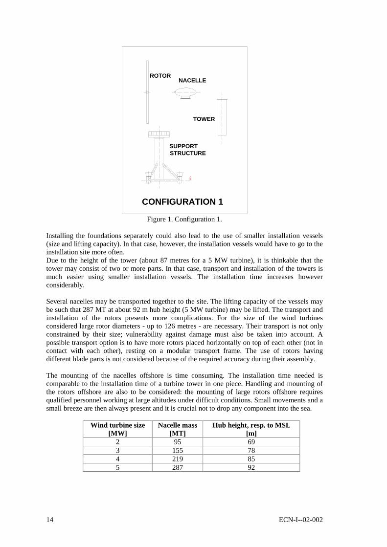
2.2 Configuration 1
Installation of major components separatelyWhen every component of a wind turbine is installed separately, more components of the sametype could be transported together to their offshore location. This depends on the transportcapacity of the considered vessels. Transporting several foundations together, for instance,would diminish their transport costs and installation time. On the other hand, a rather large stockof foundations must be present at the shore waiting for transport increasing storage costs.
14 ECN-I--02-002
NACELLE
TOWER
ROTOR
SUPPORTSTRUCTURE
CONFIGURATION 1
Figure 1. Configuration 1.
Installing the foundations separately could also lead to the use of smaller installation vessels(size and lifting capacity). In that case, however, the installation vessels would have to go to theinstallation site more often.Due to the height of the tower (about 87 metres for a 5 MW turbine), it is thinkable that thetower may consist of two or more parts. In that case, transport and installation of the towers ismuch easier using smaller installation vessels. The installation time increases howeverconsiderably.
Several nacelles may be transported together to the site. The lifting capacity of the vessels maybe such that 287 MT at about 92 m hub height (5 MW turbine) may be lifted. The transport andinstallation of the rotors presents more complications. For the size of the wind turbinesconsidered large rotor diameters - up to 126 metres - are necessary. Their transport is not onlyconstrained by their size; vulnerability against damage must also be taken into account. Apossible transport option is to have more rotors placed horizontally on top of each other (not incontact with each other), resting on a modular transport frame. The use of rotors havingdifferent blade parts is not considered because of the required accuracy during their assembly.
The mounting of the nacelles offshore is time consuming. The installation time needed iscomparable to the installation time of a turbine tower in one piece. Handling and mounting ofthe rotors offshore are also to be considered: the mounting of large rotors offshore requiresqualified personnel working at large altitudes under difficult conditions. Small movements and asmall breeze are then always present and it is crucial not to drop any component into the sea.
Wind turbine size[MW]
Nacelle mass[MT]
Hub height, resp. to MSL[m]
2 95 693 155 784 219 855 287 92

ECN-I--02-002 15
2.3 Configuration 2
Installation of the foundation followed by pre-assembled tower and nacelle, rotorseparatelyThis configuration is very similar to configuration 1. By pre-assembling the tower and thenacelle before their installation, some considerable installation time may be avoided.
The transport aspects of the turbine towers are comparable with the transport aspects consideredfor the foundations. Care must be taken not to damage the nacelles. For this reason, transport ofmore than two towers simultaneously on one vessel seems unlikely, unless they are transportedvertically.
STRUCTURESUPPORT
& TOWERROTOR
CONFIGURATION 2
NACELLE
Figure 2. Configuration 2.
The required transport space on vessels increases slightly compared with configuration 1. Themaximum mass to be lifted increases up to 507 MT at approximately 92 metres hub height (5MW wind turbine, monopod) when compared with configuration 1. This could be a limitingfactor for installation vessels.
Wind turbinesize
[MW]
Nacelle & tower massMonopod
[MT]
Nacelle & tower massTripod[MT]
Hub height,resp. to MSL
[m]2 245 234 693 343 335 784 424 419 855 507 523 92

16 ECN-I--02-002
2.4 Configuration 3
Installation of the foundation followed by the tower and finally the pre-assemblednacelle and rotorThe transport and installation of the support structure and of the turbine tower are similar to theprocedure described in configuration 1.
The transport of a pre-assembled nacelle and rotor could lead to logistic problems in handlingand supporting of the structure during transport. It seems unrealistic to consider the multipletransport of pre-assembled nacelles and rotors due to the special transport frames that it wouldbe needed. This possibility is not considered in the cost model.
NACELLE
TOWER
SUPPORTSTRUCTURE
CONFIGURATION 3
ROTOR &
Figure 3. Configuration 3.
The offshore installation of the pre-assembled nacelle and rotor means that about 387 MTshould be able to be lifted to about 92 metres hub height (5 MW wind turbine). This liftingcondition is similar to the one described under configuration 2 and could be a limiting factor forinstallation vessels.
Wind turbine size[MW]
Nacelle & rotor mass[MT]
Hub height, resp. to MSL[m]
2 126 693 207 784 294 855 387 92

ECN-I--02-002 17
2.5 Configuration 4
Installation of pre-assembled foundation and tower, followed by nacelle and rotorThis configuration is similar to configuration 1. A difference is that the pre-assembled structureis considerably larger unless it is subdivided into flanged sections. Installation of pre-assembledmonopod-tower structure is not possible.To avoid any possible damage, the transport of several units simultaneously should take placevertically. This option seems however unlikely for monopod foundations.
In the case of a jacket, the foundation and the tower should be designed integrally in order tolimit onshore pre-assembling time. More jackets-tower combinations may be transportedvertically to the site and installed in position after each other. The transport characteristics ofthis option are similar to those presented previously.
The installation of the rotors is similar to configurations 1 and 2.
CONFIGURATION 4
SUPPORT
NACELLEROTOR
STRUCTURE& TOWER
Figure 4. Configuration 4.
The maximum mass of the structure to be transported / installed is approximately 450 MT.
Wind turbine size
[MW]
Support str. & tower(Tripod, no piles)
[MT]
Top height, resp. to MSL
[m]2 318 ~663 361 ~754 387 ~825 447 ~89

18 ECN-I--02-002
2.6 Configuration 5
Installation of pre-assembled foundation and tower, followed by pre-assembled nacelleand rotor
CONFIGURATION 5
& TOWERSTRUCTURESUPPORT
ROTOR &NACELLE
Figure 5. Configuration 5.
This configuration is a combination of configurations 3 and 4 presented before. Theconsiderations presented there for pre-assembled support structure and tower, and for pre-assembled nacelle and rotor are applicable.
Wind turbine size
[MW]
Nacelle & rotor mass
[MT]
Support str. & tower(Tripod, no piles)
[MT]
Hub height,resp. to MSL
[m]2 126 318 693 207 361 784 294 387 855 387 447 92

ECN-I--02-002 19
2.7 Configuration 6
Installation of pre-assembled foundation, tower and nacelle, followed by the rotorAs an option to the configuration 5 as presented above, the pre-assembled support structure andtower can be added with the nacelle on top. A pre-assembled assembled support structure, towerand nacelle may be transported in the same way as explained for configuration 5. Theinstallation mass of this combined structure arises however up to more than 730 MT (5 MWturbine). This mass must be lifted to about 95 metres height above MSL for its installation.On the other hand, the installation time is reduced considerably compared to previousconfigurations where one or two flanged junctions must be connected offshore (tower-supportstructure junction and tower-nacelle junction).
CONFIGURATION 6
SUPPORTSTRUCTURE,TOWER &
ROTOR
NACELLE
Figure 6. Configuration 6.
An extra difficulty when installing the turbines on jacket constructions is the sensitivity of thecomplete tower (with nacelle) to vibration caused by driving the installation piles. Theconstruction should be analysed for this specific loading.
Wind turbine size
[MW]
Support structure, tower and nacelle(Tripod, no piles)
[MT]
Top height, resp. toMSL[m]
2 413 ~723 516 ~814 606 ~885 733 ~95

20 ECN-I--02-002
2.8 Configuration 7
Installation of foundation, followed by pre-assembled tower, nacelle and rotor
CONFIGURATION 7
SUPPORTSTRUCTURE
ROTOR,NACELLE& TOWER
Figure 7. Configuration 7.
The approach is to install the foundation first and separately the pre-assembled tower, nacelleand rotor together. On behalf of the transport logistics (the size of vessel and way oftransporting), a transport load case must be considered including wind loading for the turbinetower together with the (static) rotor.
The way of transporting the pre-assembled combination should be vertical: every assemblyshould be mounted temporally on a foundation made on the vessel (for instance a large pin,either at the inside or at the outside of the tower). This means that an installation vessel shouldbe adapted for this purpose. The total installation time is then probably long because thetransportation speed is relatively low.A second option for transport of the pre-assembly is a free-hanging transport. The maximummass to be transported / installed rises to about 625 MT (5 MW turbine, tripod supportstructure). To install this pre-assembly, it must be lifted up to approximately 95 m above MSL(about 105 m lifting hook height).
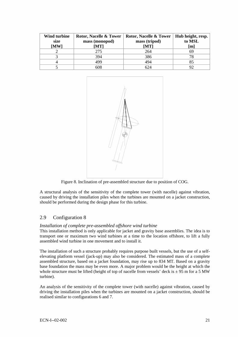
The installation of the pre-assembled tower, nacelle and rotor presents also some difficulties: thehandling of the assembly must be done in such a way that damage of the rotor does not takeplace. The tower-rotor assembly must be lifted from the temporary support, exposing at leastone blade of the rotor to possible damage if the assembly is spinning around its vertical axis,either by the lifting cable or by the crane boom. The control of the stability of the assemblyduring installation is difficult to achieve.
Moreover, when the assembly is lifted up it would tend to lean over in such a way that thecentre of gravity hangs exactly under the lifting point. Because the centre of gravity (COG) islocated rather high, the assembled structure should be held in position by auxiliary lines in orderto enable its installation.
ECN-I--02-002 21
Wind turbinesize
[MW]
Rotor, Nacelle & Towermass (monopod)
[MT]
Rotor, Nacelle & Towermass (tripod)
[MT]
Hub height, resp.to MSL
[m]2 275 264 693 394 386 784 499 494 855 608 624 92
Figure 8. Inclination of pre-assembled structure due to position of COG.
A structural analysis of the sensitivity of the complete tower (with nacelle) against vibration,caused by driving the installation piles when the turbines are mounted on a jacket construction,should be performed during the design phase for this turbine.
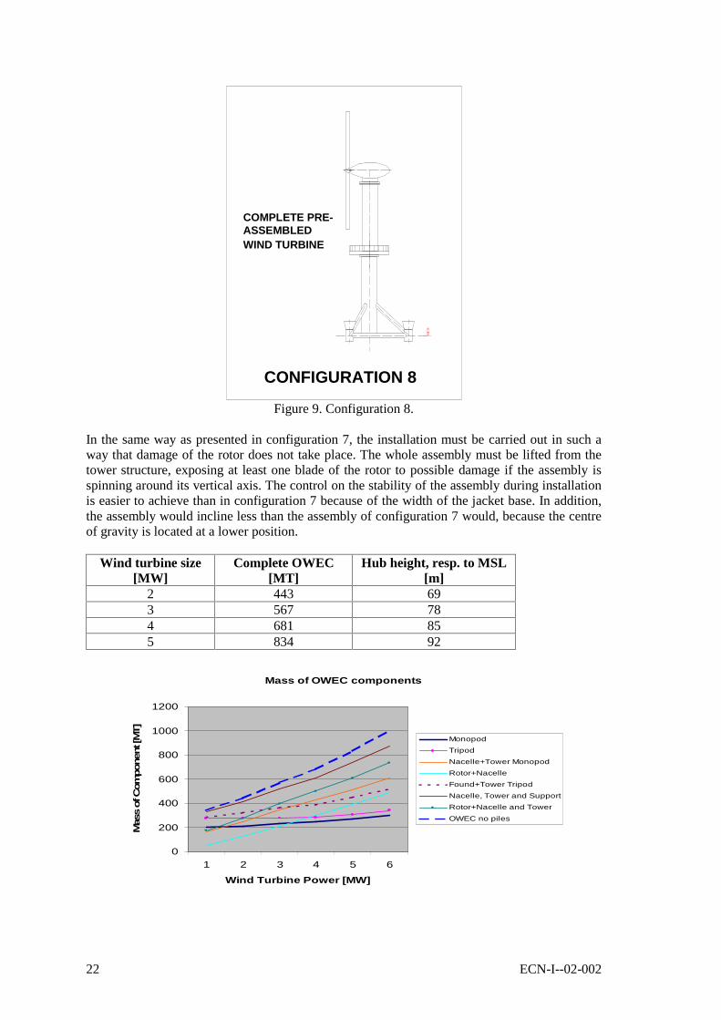
2.9 Configuration 8
Installation of complete pre-assembled offshore wind turbineThis installation method is only applicable for jacket and gravity base assemblies. The idea is totransport one or maximum two wind turbines at a time to the location offshore, to lift a fullyassembled wind turbine in one movement and to install it.
The installation of such a structure probably requires purpose built vessels, but the use of a self-elevating platform vessel (jack-up) may also be considered. The estimated mass of a completeassembled structure, based on a jacket foundation, may rise up to 834 MT. Based on a gravitybase foundation the mass may be even more. A major problem would be the height at which thewhole structure must be lifted (height of top of nacelle from vessels’ deck is ± 95 m for a 5 MWturbine).
An analysis of the sensitivity of the complete tower (with nacelle) against vibration, caused bydriving the installation piles when the turbines are mounted on a jacket construction, should berealised similar to configurations 6 and 7.
22 ECN-I--02-002
CONFIGURATION 8
WIND TURBINEASSEMBLEDCOMPLETE PRE-
Figure 9. Configuration 8.
In the same way as presented in configuration 7, the installation must be carried out in such away that damage of the rotor does not take place. The whole assembly must be lifted from thetower structure, exposing at least one blade of the rotor to possible damage if the assembly isspinning around its vertical axis. The control on the stability of the assembly during installationis easier to achieve than in configuration 7 because of the width of the jacket base. In addition,the assembly would incline less than the assembly of configuration 7 would, because the centreof gravity is located at a lower position.
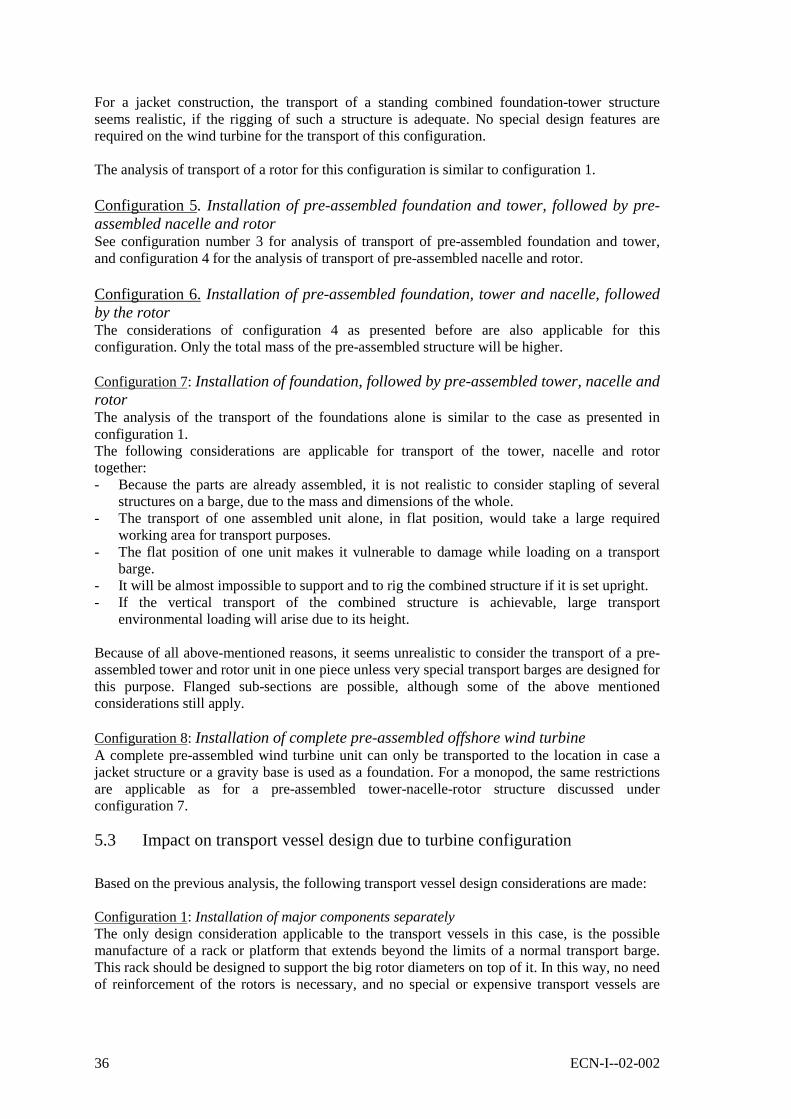
Wind turbine size[MW]
Complete OWEC[MT]
Hub height, resp. to MSL[m]
2 443 693 567 784 681 855 834 92
Mass of OWEC components
0
200
400
600
800
1000
1200
1 2 3 4 5 6
Wind Turbine Power [MW]
Mas
s of C
om
ponen
t [M
T]
Monopod
Tripod
Nacelle+Tower Monopod
Rotor+Nacelle
Found+Tower Tripod
Nacelle, Tower and Support
Rotor+Nacelle and Tower
OWEC no piles

ECN-I--02-002 23
2.10 Pro’s and Con’s of the Presented Configurations
The following summary is based on a 5 MW offshore wind turbine. The estimated dimensionsand masses are based on results from a spreadsheet based on the formulas of Appendix A. Aschematic drawing of this OWEC is given in Figure 10. Here a tripod foundation is illustrated,but the dimensions are also valid for a monopod foundation.
~20
m~2
0 m
~20
m~9
0 m
~120
m
~3 m
~10
m(M
in. l
ifti
ng
hei
gh
t)
~110
m
SEA BOTTOM
LEVELHUB HEIGHT
MSL
LEVEL
Figure 10.
Configuration 1. Installation of major components separatelyPro’s- Installation of monopods can be achieved within short intervals.- Relatively low mass of components (up to 300 MT approximately) to be lifted up to a
height of approximately 105 metres from MSL (height of lifting hook).- More rotors could be transported on one vessel.- Short transport time if more components of the same type are transported together.- The use of smaller installation vessels if installed separately.Con’s- Large installation time.- High personnel risk during installation of rotor and nacelle components.- Difficult handling / mounting of tower, nacelle and rotor components.- Vulnerability of rotor during installation offshore.- Several (small) installation vessels required or a short number of vessels leaving from and
to the site frequently.
Configuration 2. Installation of the foundation followed by pre-assembled tower andnacelle, rotor separatelyPro’s- Installation of monopods can be achieved within short intervals.- More rotors could be transported on one vessel.- No offshore installation time required for the nacelles.
Con’s- High personnel risk during installation of rotor.

24 ECN-I--02-002
- Difficult handling / mounting of rotor components.- Vulnerability of rotor during installation offshore.- Relatively high mass of components (up to 510 MT approximately for a monopod) to be
lifted up to a height of 105 metres from MSL (height of lifting hook).- Several installation vessels required or a short number of vessels leaving from and to the
site frequently.- Larger installation vessels required when compared with configuration 1 (size and lifting
capacity of pre-assembled tower-nacelle structure).
Configuration 3. Installation of the foundation followed by the tower and finally thepre-assembled nacelle and rotorPro’s- Installation of monopods can be achieved within short intervals.- No offshore installation time required for the rotor.- Less difficulty in handling and mounting of nacelle-rotor assembly when compared with
configurations 1 and 2.- Relatively low mass of components (up to 390 MT) to be lifted up to a height of 105 metres
from MSL (height of lifting hook).Con’s- High personnel risk during installation of nacelle-rotor assembly.- Most probably only one nacelle-rotor assembly can be transported at time.- Large installation time for junctions of tower and nacelle.
Configuration 4. Installation of pre-assembled foundation and tower, followed bynacelle and rotorPro’s- Integrated design of foundation and tower possible if jacket design is chosen.- Transportation of pre-assembled foundation and tower can be achieved vertically (standing)
diminishing the required transport space on a vessel and using less number of transportvessels.
Con’s- Monopod foundation is not possible in this configuration.- Relatively high mass of components (up to 450 MT approximately) to be lifted up to a
height of 100 metres from MSL (height of lifting hook).
Configuration 5. Installation of pre-assembled foundation and tower, followed by pre-assembled nacelle and rotorPro’s- No offshore installation time required for the rotor.- Less difficulty in handling and mounting of nacelle-rotor assembly when compared with
configurations 1 and 2.- Integrated design of foundation and tower possible if jacket design is chosen.- Transportation of pre-assembled foundation and tower can be achieved vertically (standing)
diminishing the required transport space on a vessel and using less number of transportvessels.
Con’s- Monopod foundation is not possible in this configuration.- Relatively high mass of components (up to 450 MT approximately) to be lifted up to a
height of 100 metres from MSL (height of lifting hook).
Configuration 6. Installation of pre-assembled foundation, tower and nacelle, followedby the rotorPro’s

ECN-I--02-002 25
- No offshore installation time required for the nacelle or for the turbine tower.
Con’s- Monopod foundation is not possible in this configuration.- High personnel risk during installation of rotor.- Relatively very high mass of components (up to 730 MT approximately) to be lifted up to a
height of 105 metres from MSL (height of lifting hook).- Extra load case for the nacelle due to installation vibrations.
Configuration 7. Installation of foundation, followed by pre-assembled tower, nacelleand rotorPro’s- Installation of monopods can be achieved within short intervals.- No high personnel risk.- No difficulty in handling and mounting of rotor components.
Con’s- Purpose built (or adapted) large transport / installation vessel(s) required.- Relatively very high mass of components (up to 625 MT approximately) to be lifted up to a
height of 105 metres from MSL.- Extra load cases for transport of pre-assembled tower, nacelle and rotor of turbines.- Vulnerability of rotor to damage during installation.
Configuration 8. Installation of complete pre-assembled offshore wind turbinePro’s- Very short installation time.- Small chance of damage to the construction due to handling.- No high personnel risk.- No difficulty in handling and mounting of rotor components.- Low vulnerability of rotor during installation offshore.- Construction availability of wind turbine maybe to the same level as required installation
time (one assembly every week).Con’s- Monopod foundation is not possible in this configuration.- Only one (maximum two) assemblies can be transported at a time to the site.- Large transport and installation vessel(s) required (maybe purpose built or adapted vessels).- High mass of assemblies, about 835 MT, to be lifted over a large height (105 m height of
lifting hook), i.e. big strong cranes required.- Extra load case analysis due to installation vibrations.


ECN-I--02-002 27
3. OFFSHORE TURBINE TYPES, IMPACT ON DESIGN
3.1 Impact on Turbine Design due to Transport
Each of the configurations presented in the previous chapter will affect the wind turbine design.The way of transport shall influence for instance the number of lifting eyes and requiredreinforcements in the construction. The same applies to transport by means of towedconstruction instead of normal barge transport. Temporary (removable) construction parts mustbe taken into account during the design phase.Another consideration would be the parking of blades when transporting the tower together withits rotor or the use of retractable rotor blades to minimise the physical transport space.
All these considerations will have an impact on the design costs of offshore wind turbines andwill affect the transport costs as well. A cost estimation difference is made in chapter 5 of thisreport when considering these issues.
3.2 Impact on Turbine Design due to Installation
Besides the transport, considerations presented above, the way of installing the wind turbineoffshore shall have an impact on the design of the structure. Some examples are:- The parking of blades when installing the pre-assembled tower and rotor;- Bolted connections with their fatigue problems;- The choice of flanged connections;- The choice of the location of the working platform connected to the structure.
All these considerations will have an impact on the design costs of offshore wind turbines andcould influence the installation costs as well. A cost estimation difference is made in chapter 6of this report when considering these issues.
3.3 Impact on Turbine Design due to Offshore Location
The location of the wind turbines offshore affects the choice of the material quality, corrosionprotection and lightening protection. These choices will have an impact on transport andinstallation costs only through a change in the total mass of the construction and through achange in the sensibility of the construction during handling. Therefore, they will not beconsidered in this report.
Some examples of the impacts on turbine design have already been analysed in [1].
3.4 Impact on Turbine Design due to Maintenance
There are two aspects to be considered regarding the impact on design in regard to maintenance:- Impact on design of the offshore construction in order to minimise maintenance.- Safety of personnel during maintenance.
To analyse the impact on design it is necessary to establish a difference between heavy and lightmaintenance, based on the mass of the components to be replaced if necessary.For light maintenance, no design changes are expected that would affect the transport or theinstallation.For heavy maintenance, internal lifting equipment could be considered to lift turbine parts upand to lay them down on a platform at the lower end of the turbine tower. Another possibility isthe use of helicopters to lift these heavy parts, where a helicopter platform should then benecessary.

28 ECN-I--02-002
Even though the turbines for an offshore location are specifically designed not to require muchmaintenance, they must be designed to receive personnel during calm / harsh weather conditionssafely.Due to the size of the expected offshore wind farms and due to the expected number of windturbines in a farm, it is supposed that spare components will be off-the-shelves and thereforethere will be no delay in the manufacturing process of spare components.
The access to (each) wind turbine may be realised in one of the following three ways:- By maintenance vessels.- By helicopter.- Using both alternatives, maintenance vessels and helicopter.All three possibilities are restricted by their operational conditions: the maximum sea state orwind speed/visibility conditions.
The impact on the wind turbine design related to maintenance, may be resumed by thefollowing requirements:- A lay-down platform for heavy maintenance equipment.- A mooring platform to accept the maintenance vessels.- Internal railing and platforms for climbing of maintenance personnel.- Internal platform in conditioned nacelle for maintenance purposes.- An external helicopter platform including ladders, railing and ancillaries in order to enter
the nacelle.
All above-mentioned items will increase design costs, slightly increase construction mass (andthus transport and installation costs) and slightly increase the sensitivity of the constructionduring handling. An exception forms a helicopter platform. If installed separately, it may resultin a substantial increase of transport and installation costs.All these factors are taken into account in the calculation of transport and installation costs.
3.5 Impact on Turbine Foundation due to Vibration Induced by Waves
The impact of vibration induced by waves on the turbine foundation, like the avoiding of wavefrequency in the range of natural frequency of the foundation, is not accounted for.

ECN-I--02-002 29
4. OFFSHORE WIND TURBINE DIMENSIONS AND MASS
4.1 General
To estimate the mass and dimensions of the tower and foundation of the OWEC a roughanalysis of the stresses present in the structure is carried out.The loads considered for the analysis are the result of a correlation between quasi-static wind,wave and current loads. For each load case considered, this correlation is analysed in chapter4.2.
It must be noticed that this calculation is done with the only purpose to estimate the mass andthe dimensions of such a construction in order to facilitate an estimation of the transport andinstallation costs. The real dimensions of an offshore wind turbine follow from a much moreelaborated load analysis.
The following considerations must be taken into account when calculating the stresses in thesteel structure:- The maximum allowable stress in the material is given as a factor of the yield stress. This
factor is defined for operational (a) and temporary (b) conditions respectively as 0.6 and 0.8,see reference [2], part 3, chapter 1, chapter 6 (C 200).
- For elastic design, a material coefficient must be used for steel structures. The coefficientused equals 1.15, see reference [2], part 3, chapter 1, chapter 6 (B 200).
- The stress used for calculation is the equivalent stress as formulated by Von Mises inEquation 1:
221
22
21 *3* τσσσσσ +−+=e
see reference [2], part 3, chapter 1, chapter 6 (D 103).- The structural members must also be designed against buckling. The criterion used to avoid
buckling on the tower is given by D/wt > 175. As an alternative, the critical momentworking on the construction may be considered using a formula for combinations of verticalload and bending moment (see ref. [4]).
- The yield stress of a material varies with the plate thickness. The considered material in thisanalysis is S355J2G3 (Euronorm) with a minimum yield stress of 335 N/mm2 for wallthickness below 63 mm. In appendix B, three typical steel materials with their properties arepresented, namely: S235J2G3, S275J2G3 and S355J2G3.
4.2 Choice of Foundation Type
Some basic foundation types are considered for offshore wind turbine applications:- Gravity bases (concrete plates and grouted caissons)- Guyed turbine towers- Monopods (driven pile, drilled pile, suction pile)- Jackets (tripods, lattice towers, or similar designs)- Suction caissons- Floated foundations
Gravity bases have been used already in several wind farms in the Danish waters. These farmsinclude relative small offshore wind turbines in relatively shallow waters. The installation timefor these farms was not very critical due to the limited number of turbines and the purpose of

30 ECN-I--02-002
the farm (gain experience). For these reasons they are of limited relevance when consideringlarge wind farms in deeper waters as in the North Sea.Gravity bases could be either transported on transport barges or be self-floating (hollow)structures that may be grouted once installed. In most cases, gravity bases need a sea bottompreparation before being put into place.
Monopods have been used very frequently for onshore and offshore wind farms. Due to theirrelative low mass and small dimensions, they are considered as the most cost effectivefoundation solution at this moment. Stability problems appear when water depths increase.Driven piles are mostly used in sandy sea bottoms. To prevent that the monopod foundationloses clamping load at its base, scouring of the seabed must be prevented. As an alternative, themonopod foundation is driven deeper.Hard sea bottoms as rock and clay may need the use of drilled instead of driven piles. Suctionpiles are considered an option, although they have not been applied up to now.
Jackets (tripods and lattice towers) are considered necessary for deeper waters. Both type ofstructures make use of smaller driven (or drilled) piles than monopods, three as a minimum, andneed sea bottom preparation or another aligning technique to ensure tower verticality whenfinally installed. Lattice towers may be lighter than jackets, but requires much more weldingwork. An optimum has not yet been found, although it is claimed by KEMA that their latticetower design leads to minimum costs [5].
Instead of using driven or drilled piles, the use of suction piles is possible. Suction piles may beremoved after use by inverting the installation procedure. Besides, instead of consideringseparate suction piles, a suction caisson may be used. A suction caisson is a large diametersuction pile that could be used as a base for monopods. The transportation to location of suctionpiles or a caisson could simply be self-floating.At the time of this writing, no technical information about suction caissons and their respectivedesign loads is known, reason why they won’t be considered here.
In this report only monopod, tripod and gravity base foundation types will be considered. Otherfoundation types are not further investigated.
The mass of monopod, tripod and gravity base structures is analysed. The costs of transport,installation operation and maintenance of wind turbines placed on any type of foundation arewell analysed. If in the future a different type of foundation becomes realistic, it could beanalysed on the same terms.
4.3 Load Cases
Two different load cases are considered in the analysis of the offshore structure of a windturbine: operational loads and extreme wind loading. Fatigue loading, frequency analysis due todynamic loading or accidental loads due to, for instance, a barge collision are not included intothis analysis.
Operational LoadsOperational loads are the maximum loads acting on the wind turbine structure when the turbineis working. As a basis of design, the cutout wind speed (25 m/s at hub) is considered to yield thedimensioning operational loading.The cutout wind speed is considered a steady wind speed, which implies that the wind loads willinduce wave loading. For the estimation of the wave loads, a wave height equal to thesignificant wave height at a determined location with a 1-year return period is used.The third load component in the analysis is the sea current. Compared with the wind and thewave loads the loading from current is very low, but it will not be neglected.

ECN-I--02-002 31
In the case of operational loads, waves and wind directions may be assumed parallel because thewaves considered are induced by the steady wind condition. The current will be assumed to bein the same direction as the wind and waves. This conservative assumption means that the fullcurrent load will act in addition to the other two.
The distributed loads considered and the stresses found in the structure are presented in thefigures. Note that both tower diameter and wall thickness of the tower vary linearly from the top(hub height) up to the connection point between the tower and the foundation.
No dynamic amplification factor has been used in the analysis because the loads considered arescaled up values that were derived from a dynamic analysis for an existing wind turbine [6].
Load distribution over turbine - Monopile
-40.0
-20.0
0.0
20.0
40.0
60.0
80.0
100.0
0 50 100 150 200
Total load [kN]
Tu
rbin
e co
ord
inat
e [m
]
Operational Conditions
Extreme w ind conditions
Stress distribution over turbine height - Monopile
-40.0
-20.0
0.0
20.0
40.0
60.0
80.0
100.0
0 100 200 300
Equivalent stress [N/mm2]
Tu
rbin
e co
ord
inat
e [m
]
Operational conditions
Extreme w ind conditions
Figure 11 Figure 12
Extreme Wind LoadingExtreme loading refers here to the extreme wind speed having a probabilistic 50-year returnperiod. In this case, for each 10 minutes average speed above 25 m/s, the wind turbine isdisconnected (idle). The horizontal load acting on the rotor is related to the horizontal load of areference turbine.
For the considered turbine for a mean wind speed of 56 m/s (3 seconds average peak wind speedof 70 m/s), the axial load is 84 kN. This load is up-scaled for the considered turbine accordingto Equation 2:
2___ )
_
_(*
refrefrotorwindrotorwind rotorD
rotorDFF =
The corresponding wind speed acting on the tower is described as follows:- At hub height a wind speed of 70 m/s is present (=Ve50).- The wind profile acting on the tower diameter is given by the extreme wind model (EWM),
according to [7], Equation 3:
11.0)(*)(hub
hub z
zVzV =

32 ECN-I--02-002
The correlation between wind speed and wave loading is taken to be parallel. The used heightfor the waves is the maximum wave height of the spectrum, determined for a given scatterdiagram according to the JONSWAP formula, Equation 4:
sHH *8.1max =
The current speed is assumed to deviate by 30 degrees from the direction of wind and waves. Abrief analysis shows that the current speed is not relevant for the determination of the stressesand may as well be disregarded.Other extreme load cases have not been investigated.
4.4 Estimation of Mass and Dimensions of Offshore Wind Turbines
In the following summary, two offshore wind turbines are considered: a 3 MW and a 5 MWturbine. It is not the intention of this study to do an in depth analysis of mass and lengths ofturbines, but to present a breakdown of mass and dimensions as a help tool for doing costsanalysis. A breakdown of the mass and dimension of the wind turbine, as used in this report, isanalysed in Appendix A.
The following parameters are used as a base for the estimation:- The water depth in which the OWEC is installed is 20 metres;- A minimum clearance between the tip of the blades and sea water level (MSL) is 20 metres;- The wind turbines have a specific power of 400 W/m2 rotor area;- The rotors of the OWECs have 3 blades;- The mass of the blades is estimated using the up-scaling of blade mass as presented in
reference [8], M=0.10x(D_rotor)2.63, D_rotor in [m] and M in [kg];- The mass of the nacelles is estimated with the following empirical formula derived in
reference [8], M=2.6x(D_rotor)2.4, D_rotor in [m] and M in [kg]. The gross of the data usedto derive this formula is based on small turbines (diameter of rotor under 40 m), so itsvalidity is still doubtful.
The results derived are presented in the following table:
Turbine type Turbine part Dimensions[m]
Mass[MT]
Monopod foundation Length 49.3 ~230Tripod foundation Base x h (15x15) x 28.7 ~279Tower D_tower x h 4 x 72.5 ~185Nacelle D x L unknown ~155Rotor (3 blades) D_rotor 98 ~50
3 MW turbine
Total MonopodTotal Tripod
~625~665
Monopod foundation Length 50.3 ~270Tripod foundation Base x h (15x15) x 28.7 ~310Tower D_tower x h 4.5 x 86.7 ~230Nacelle D x L unknown ~290Rotor (3 blades) D_rotor 126 ~100
5 MW turbine
Total MonopodTotal Tripod
~875~930
Table 1. Mass and dimensions of a 3 MW and a 5 MW OWEC.
Despite the fact that the dimensions and mass of the wind turbine are known, they are notfurther used in the estimation of the transport and or installation costs. The dimensions and massare calculated to get an idea of the structures to be transported/installed. Based on thisinformation, the transport and installation vessels are determined.

ECN-I--02-002 33
5. ANALYSIS OF TRANSPORT COSTS
5.1 General
The costs of transport of (sub-)structures related to wind energy converters and associated itemsoffshore depend on several factors. Some of the factors are:- Cost of hired equipment for transport- Number of items to be transported, short and long term- Dimension of substructure to be transported- Sensitivity of substructure for damage during transport- Delays due to weather conditions- Costs of insurance
All above-mentioned factors are interrelated. In this section, each considered factor is treatedindependently from the others and is considered a lump sum.
The types of structural components to be considered are:- Foundation- Turbine tower- Nacelle- Turbine rotor
Besides, combinations of the components may also be considered:- Transport of previously pre-assembled tower and nacelle (Configuration 2)- Transport of previously pre-assembled nacelle and rotor (Configurations 3 and 5)- Transport of previously pre-assembled foundation and tower (Configurations 4 and 5)- Transport of previously pre-assembled foundation, tower and nacelle (Configuration 6)- Transport of previously pre-assembled tower, nacelle and rotor (Configuration 7)- Transport of the turbine as a whole (Configuration 8)
In addition, there are also different options for the foundation:- Gravity base- Guyed turbine tower- Monopod- Jacket, tripod design- Jacket, lattice design
Finally, the way of anchoring a foundation to the sea bottom may be achieved by the mass ofthe foundation itself or by the use of drilled, grouted, driven or suction piles.
When considering the involved transport costs many combinations of constructions, assemblymethods and anchoring methods are possible. Vessel capacity and costs are estimated, based onexpertise of senior engineers in the offshore industry.
In the following paragraphs, the impact of the turbine design on the transport costs is discussedfirst. Secondly, the impact on transport vessels due to a chosen turbine design is presented.Thirdly, the transport costs for the configurations are discussed. Finally, the impact on the costsdue to bad-weather delays is analysed. Costs of insurance have not been included in this report.
All derived costs have been deducted for the year 2001.

34 ECN-I--02-002
5.2 Impact of Turbine Design on Transport (Costs)
In all configurations, flanged sub-sections are mentioned. In chapter 6.2 of this report, theimpact of this design on installation is discussed.
The turbine design could have a major influence on the transport costs to the offshore location.Examples of this are the choice for two or three blades for a rotor, or the design of a retractableblade for transport purposes.For the analysis of the transport (costs) of the presented configurations, the following generalassumptions are made:1 The rotor of the wind turbine consists of three (non-retractable) blades.2 The boat landing (platform) is located at mean sea level.3 The foundation of the turbine ends at a certain height above mean sea level.4 The required maintenance platform is a part of the foundation (at the upper end) or it is a
part of the turbine tower (at the lower end).5 The foundation of the turbine does not include any other external maintenance platform.6 The offshore turbine does not include a helicopter platform on top. If such a platform is
required, it is transported (and installed) separately. The necessity of a helicopter platformand cost is not analysed.
In addition to these assumptions each configuration as presented in chapter 2 is analysed:
Configuration 1: Installation of major components separatelyBecause all parts of the wind turbine are installed separately, all foundation(s) may be installedfirst. The foundations include a boat landing (platform) at the upper end, or at least a protectionagainst vessel collision and a maintenance platform, just below the possible connection flangelevel. This part must be protected during transport.
The transport to location of the monopods may be done using a transport barge or they may betowed (floating).If transported on a barge, the lengths of the monopod may be inconveniently large (about 50metres in one piece). It seems improbable that this pile will be cut in pieces for transport and bewelded together before installation. This means that a transport area on a barge will be neededof at least 50 metres long if the pile is made out of one piece. Even if the pile is transportedinclined by an angle of 15 degrees, the needed length will be still 48 metres. The pile designmust include lifting points able to carry a load that varies between 200 and 300 MT. Flangedsub-sections could be an option, provided that the flange remains above sea bottom level afterinstallation of the pile.If the piles are towed to location, their design must include watertight compartments orattachment points to external compartments. Probably two towing tugs will be needed for self-floated transport. The transport of more than one pile at a time by this method is notunthinkable.The transport to location of jacket foundations will be slightly different: they may betransported upright. The minimum transporting areas of one unit will be limited by its base size,i.e. for a configuration of three piles at a radius of 8 metres, a triangular area of about 14 metrestriangle size is needed (approx. 40 m2) or by the size of the maintenance platforms. This meansthat no special design of a jacket is needed to satisfy the transport limitations.The transport of gravity base foundations may be achieved in two ways: self-floated or on atransport barge. If self-floated, grout is needed on the basement of the gravity base after itspositioning on the location. This grout must be transported separately. The transport of a gravitybase on a barge is similar to the transport of a jacket.The foundation of a guyed turbine tower will probably be a slender monopod.
The following points need to be considered for the transport of the towers for this configuration:- The mass of the towers varies between 120 and 220 MT for the 1 MW – 5 MW range

ECN-I--02-002 35
- The length of the towers is also considerable, being between 52 and 87 metres long.- The towers may include a maintenance platform, located at the lower end.
It is expected that the towers will be transported horizontally, supported in order to avoiddamage, on barges with at least 90 metres long transport area. Another option is to subdivide thetower into flanged sub-sections. The tower design must include lifting points. No other specialfeatures are expected for the design of the wind turbine towers.
The rotor diameter may be as much as 126 metres, for the 1 MW – 5 MW range. This meansthat very large and/or wide barges should be used to transport a three-bladed rotor, unless theblades are retractable or the blades may protrude from the transport barge. In the latter casepossible loading during transport must be investigated at forehand. Two bladed rotors do notneed any special design consideration, if there is a transport barge long enough to support a 126meters rotor diameter.
Another option is to transport the blades of a rotor separately and to connect them to the hubprior to installation. In this case, the transport barge will not constitute any restriction, but theconnection of the blades to the hub must be such that a straightforward installation in offshoreenvironment can take place.
Configuration 2. Installation of the foundation followed by pre-assembled tower andnacelle, rotor separatelyThe considerations for this configuration are similar to configuration 1. The differences are:- The tower-nacelle assemblies have a mass varying between 160 and 520 MT for 1 MW to 5
MW respectively.- The length of the tower-nacelle assemblies is also considerable (approximately between 60
and 95 metres, including nacelle).
It is expected that the assemblies will be transported horizontally, supported in order to avoiddamage, on barges with at least 100 metres long transport area. Protruding of assemblies frombarges is an option. Towers subdivided into flanged sections, like the case of the foundationdiscussed previously, are possibly but then special measures would be needed for the electriccables.
Configuration 3. Installation of the foundation followed by the tower and finally the pre-assembled nacelle and rotorThis configuration is very similar to configuration 1. The only difference is the pre-assemblednacelle and rotor structure. It seems unlikely that the pre-assembled nacelle-rotor structures maybe stapled for transport. This means that one transport vessel must be used for each pre-assembly.
Configuration 4. Installation of pre-assembled foundation and tower, followed bynacelle and rotorIf only the transport aspects are considered, it seems unrealistic to choose for transport of pre-assembled foundation-tower structures for monopod configurations. If this is the case, thetransport barges for a 5 MW turbine should have a working area with a length of at least 140metres, unless the combined pile-tower structure may protrude from the barge or it is made outof flanged sub-sections. The construction also includes a boat landing and a maintenanceplatform that must be protected during transport. This means that the whole structure must besupported on several points (because it may not be placed on the working area). Forconfiguration 4, it seems more logical to transport the foundation and tower separately (maybeon the same barge) and to connect the parts before installation.
36 ECN-I--02-002
For a jacket construction, the transport of a standing combined foundation-tower structureseems realistic, if the rigging of such a structure is adequate. No special design features arerequired on the wind turbine for the transport of this configuration.
The analysis of transport of a rotor for this configuration is similar to configuration 1.
Configuration 5. Installation of pre-assembled foundation and tower, followed by pre-assembled nacelle and rotorSee configuration number 3 for analysis of transport of pre-assembled foundation and tower,and configuration 4 for the analysis of transport of pre-assembled nacelle and rotor.
Configuration 6. Installation of pre-assembled foundation, tower and nacelle, followedby the rotorThe considerations of configuration 4 as presented before are also applicable for thisconfiguration. Only the total mass of the pre-assembled structure will be higher.
Configuration 7: Installation of foundation, followed by pre-assembled tower, nacelle androtorThe analysis of the transport of the foundations alone is similar to the case as presented inconfiguration 1.The following considerations are applicable for transport of the tower, nacelle and rotortogether:- Because the parts are already assembled, it is not realistic to consider stapling of several
structures on a barge, due to the mass and dimensions of the whole.- The transport of one assembled unit alone, in flat position, would take a large required
working area for transport purposes.- The flat position of one unit makes it vulnerable to damage while loading on a transport
barge.- It will be almost impossible to support and to rig the combined structure if it is set upright.- If the vertical transport of the combined structure is achievable, large transport
environmental loading will arise due to its height.
Because of all above-mentioned reasons, it seems unrealistic to consider the transport of a pre-assembled tower and rotor unit in one piece unless very special transport barges are designed forthis purpose. Flanged sub-sections are possible, although some of the above mentionedconsiderations still apply.
Configuration 8: Installation of complete pre-assembled offshore wind turbineA complete pre-assembled wind turbine unit can only be transported to the location in case ajacket structure or a gravity base is used as a foundation. For a monopod, the same restrictionsare applicable as for a pre-assembled tower-nacelle-rotor structure discussed underconfiguration 7.
5.3 Impact on transport vessel design due to turbine configuration
Based on the previous analysis, the following transport vessel design considerations are made:
Configuration 1: Installation of major components separatelyThe only design consideration applicable to the transport vessels in this case, is the possiblemanufacture of a rack or platform that extends beyond the limits of a normal transport barge.This rack should be designed to support the big rotor diameters on top of it. In this way, no needof reinforcement of the rotors is necessary, and no special or expensive transport vessels are

ECN-I--02-002 37
required. This possibility would be subjected to local legislation because of the extended lateraldimensions during transport.If more rotors are to be transported simultaneously, these platforms must also include thepossibility of being piled up.
Configuration 2. Installation of the foundation followed by pre-assembled tower andnacelle, rotor separatelyThe difference with configuration 1 is the difficulty to transport a nacelle that is assembled tothe turbine tower.If the pre-assembly is to be transported horizontally, special supports are needed in order tokeep the nacelle free form interaction with the deck of the transport vessel. Probably no morethan one pre-assembled tower and nacelle structure would be transported simultaneously in onevessel.If the pre-assembly is to be transported vertically, transport vessels with special features arerequired in order to keep the pre-assemblies safe in vertical position under the action of thetransport loads. Special transport vessels are not considered into this cost model.
Configuration 3. Installation of the foundation followed by the tower and finally the pre-assembled nacelle and rotorThis configuration differs from configuration 1 in the space on the transport vessel that the pre-assembly requires for its transport. The transport of this pre-assembly is possible, but it seemsthat a space frame would be required therefor. Moreover, the pre-assembly is very sensitive todamage during (de-) embarkation. If these technical issues were solved, probably no more thantwo pre-assemblies would be transported simultaneously in one vessel.
Configuration 4. Installation of pre-assembled foundation and tower, followed bynacelle and rotorThis configuration is considered only when the support structure is not a monopod. If that’s notthe case, its transport will be similar as discussed under configuration 1, only the height will bemore and thus an adapted rigging method would be needed.
Configuration 5. Installation of pre-assembled foundation and tower, followed by pre-assembled nacelle and rotorThis configuration is a hybrid variant of configurations 3 and 4. All considerations presentedthere are valid. No other special requirements are necessary.
Configuration 6. Installation of pre-assembled foundation, tower and nacelle, followedby the rotorNo special vessel designs are required for this configuration. The transport of the rotor(s) mayoccur in the same way as for configuration 1.
Configuration 7: Installation of foundation, followed by pre-assembled tower, nacelle androtorThe transport of the foundations may occur similarly to configuration 1. The transport of thecombined tower, nacelle and rotor seems impossible without adapting an existent transportvessel or even without a new vessel design.If transported horizontally, similar considerations as presented under configurations 2 and 3 areapplicable. In this case, the pre-assembly will be even more sensitive to damage than whencompared with configuration 3. Besides, only one pre-assembly could be transported in onevessel.If the pre-assembly is to be transported vertically, transport vessels with special features arerequired in order to keep the structure safe in a vertical position under the action of the transportloads. More than one pre-assembly could then be transported simultaneously in one barge.Special transport vessels are not considered into this cost model.
38 ECN-I--02-002
Configuration 8: Installation of complete pre-assembled offshore wind turbineThe transportation of pre-assembled wind turbines (in one piece) is only possible in case of theuse of a jacket structure or a gravity base as foundation. In these cases, a special transport bargeis expected to be required.
The aspects that are important for determination of an adequate transport barge are:- Maximum working area of an erected wind turbine.- Maximum external loading acting on the structure during transport.- Minimum required rigging for transport and available space to realise this rigging.
Special designed transport vessels are not considered in this report.
5.4 Way of Transport to Location
The transport of the wind turbine (parts) to the location offshore can be realised by means oftugs towing the floated structure or by transport on a transport barge.
Floating transport may only be applied for turbine parts that comply with the followingrequirements:- They are not sensible for damage due to water ingress; this applies only for foundation parts
and turbine tower parts without nacelle,- They have sufficient buoyancy; applying extra buoyancy to the structure is not considered
an economic option. This implies that, if towed, these parts must include watertightcompartments (additional steel), using for instance removable covers.
Based on the considerations as stated above, only the support structures of the offshore windturbines are considered adequate for floated transport. Floated transport of combinations offoundation with other components or even floated transport of a complete wind turbine could beachievable, but it is not included as an option in the cost model.
Another problem that arises when considering towable structural parts is their installation oncethe offshore location is reached: the structures must include facilities to position them on theirbases. This particularly applies to tower parts.
For towed transport, two towing tugs would be needed to transport the structure to its locationoffshore. In case of barge transport, the required equipment depends on the combination oftransport and installation by the same barges. The following equipment is identified fortransport purposes:
Separated transport and installation- 1x towing tug- 1x cargo barge- 1x assistance tug (optional)Or- 1x crane barge with enough cargo area- 1x assistance tug (optional)
Combined transport and installation- 1x self-elevating work vessel (jack-up)Or- 1x construction vessel

ECN-I--02-002 39
(Sub)structure Self-floatedtransportation
Bargetransportation
Configuration 1:Monopod foundation YES YESJacket foundation, tripod design NO YESJacket foundation, lattice design NO YESGravity base foundation YES YESGuyed turbine foundation YES YESTurbine tower NO YESNacelle NO YESRotor NO YESGuyed turbine tower YES YESConfiguration 2:Turbine tower and nacelle NO YESFor other components see Configuration 1Configuration 3:Rotor and Nacelle NO YESFor other components see Configuration 1Configuration 4:Monopod foundation and tower NO 1 NOJacket foundation and tower NO YESGravity base foundation and tower YES 2 YESGuyed turbine foundation and tower NO NOFor other components see Configuration 1Configuration 5: see configurations 3 and 4Configuration 6:Monopod foundation, turbine tower and nacelle NO YESJacket foundation, turbine tower and nacelle NO YESGravity base foundation, turbine tower and nacelle NO YESGuyed turbine foundation, turbine tower and nacelle NO YESConfiguration 7:Turbine tower, Nacelle and Rotor NO YESFor other components see Configuration 1Configuration 8:Complete pre-assembled wind turbine NO YESTable 2. Overview of transportation means for the different substructures.
5.5 Transport Steps
For each of the steps in the process of transportation to the site, a lump sum is estimated whenapplicable.
For transport of towed structures, the following procedure is applicable:- Transport of structure from fabrication hall to quay ±0 k 3
- Rent of quayside ±200 k 4
- Lift the structure from quayside into the water ±0 k- Connect the structure to a towing tug ±0 k
1 A pre-assembled monopod support structure - turbine tower does not satisfy the requirements mentioned above.2 This floated option should be investigated. It is assumed here to be possible.3 The transport cost of the substructure to the quayside is mostly a part of the substructure’s price.4 Estimated price for a three months period.

40 ECN-I--02-002
- Transport to offshore location see specification
For transport on a transport barge the steps are:- Transport of structure from fabrication hall to quay ±0 k- Rent of quayside ±200 k- Loading of structure from quayside on transport barge ±0 k- Transport to offshore location see specification
5.6 Cost of Transport Equipment
In the cost model 6 types of vessels are considered for transport and installation. The author ofthis report does not know some of these costs and therefore they have been estimated. Anoverview of the costs of these vessels is given in the next table:
Equipment (De-)mobilisation Costs 5 Operational Costs 6
(day-rate)Towing tugCargo bargeJack-upConstruction vesselCrane barge (sheer leg)Crane barge (derrick)
Table 3, Cost of transport equipment
5.7 Estimation of Transport Time
The transport time can be subdivided into the following steps:- Mobilisation of transport barges to the transport quay ± 3 days- Loading of structures from the quay onto the vessel ±0.5 day- Transport time to site ±0.25 day- Time for anchoring on site (if applicable) 0 7
- Time for unloading of structure ±0.5 day- Mobilisation time back to the quay ±0.25 day
For the calculation of transport costs, the mobilisation time is not considered because mostcompanies charge a lump sum for the mobilisation of their equipment. The other times are alltogether equal to 1.5 day. This ‘fixed’ time multiplied by the day-rate of the vessel is added intothe cost calculation formula.In the list above, the time needed by the transport barges to moor, in order to remain stableduring unloading of the transported structures, is neglected. This will differ depending on thetransport vessel used, especially when the use of one vessel for a combination of transport andinstallation is preferred.
The costs of transporting the wind turbines are estimated based on the in chapter 2 presentedconfigurations. Depending on the vessel used, transport of all turbine substructures separatedmay be less expensive than a whole wind turbine at once. Based on these configurations, twentydifferent turbine substructures may be identified.Two parameters are defined to quantify the costs of transporting the turbine substructures:Nsim_tr and Nday_tr.
5 Prices are not given here, see Ref [3]. Mobilisation costs are also given as a number of days (preparation time)multiplied by the day-rate.6 Prices are not given here, see Ref [3].7 Time for anchoring is neglected. From discussions with offshore experts, it seems that this time will be less than 3hours for a large vessel. Anchoring is then done by assistance tugs.

ECN-I--02-002 41
Nsim_tr represents the maximum number of substructures that can be transportedsimultaneously on a vessel. Nday_tr represents the maximum number of substructures that canbe delivered to their final location within one day by a vessel. These two parameters are furtherexplained in section 5.11.As an example, the value of these parameters is presented in the next table for three of theidentified 20 turbine substructures. The dimensions of the substructures and their mass have notbeen taken into account. Special transport vessels are also not considered.The mentioned transport times do not include delays because of bad weather conditions. Thetransport capacity (number of units that can be transported with one vessel) have been estimatedbased on the considerations given in chapter 5.3.
Transport equipment Simultaneoustransport
capacity (units)
Transportcapacity 8
per day
Substructure
Cost model parameter Í Nsim_tr Nday_tr2x towing tugs 2 21x cargo barge & 1x tug 4 2Jack-up 10 1Construction vessel 8 1Sheer leg 0 0
Monopod foundation
Crane barge 0 02x towing tugs 0 01x cargo barge & 1x tug 1 1Jack-up 4 1Construction vessel 2 1Sheer leg 0 0
Jacket foundation,tripod or latticedesign
Crane barge 1 12x towing tugs 0 01x cargo barge & 1x tug 1 1Jack-up 1 1Construction vessel 1 1Sheer leg 0 0
Complete pre-assembled windturbine (jacketfoundation)
Crane barge 0 0Table 4, Transport of turbine substructures
Example:The transport of 20 monopods with one cargo barge and tug, takes 20/4 = 5 travels from shoreto site because this transport combination can transport 4 units simultaneously (Nsim_tr = 4).The number of days working at sea will be 20/2 = 10, because this transport combination is ableto transport 2 units to the site in one day (Nday_tr = 2). The total working time is then 10 +5*1.5 = 17.5 days.
5.8 Definition of Maximum Sea State Conditions for Transport
To analyse the availability of transport barges, it is possible to distinguish two types ofmaximum sea states:- a maximum sea state for travelling to location and- a maximum sea state for stable floating condition on the site, i.e. during the transhipment of
the structures from the transport to the installation vessel.
8 This parameter represents the number of turbine substructures that can be transported from the quay to the offshorelocation, or from one location to another, in good weather conditions. It is estimated to be valid up to 40 km from theshore. It has been estimated independently from the substructure’s dimensions and mass.
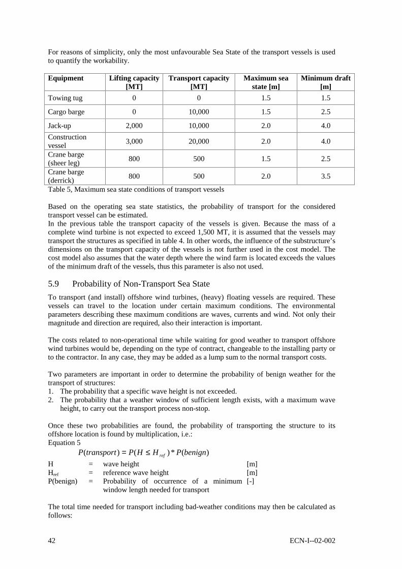
42 ECN-I--02-002
For reasons of simplicity, only the most unfavourable Sea State of the transport vessels is usedto quantify the workability.
Equipment Lifting capacity[MT]
Transport capacity[MT]
Maximum seastate [m]
Minimum draft[m]
Towing tug 0 0 1.5 1.5
Cargo barge 0 10,000 1.5 2.5
Jack-up 2,000 10,000 2.0 4.0
Constructionvessel
3,000 20,000 2.0 4.0
Crane barge(sheer leg)
800 500 1.5 2.5
Crane barge(derrick)
800 500 2.0 3.5
Table 5, Maximum sea state conditions of transport vessels
Based on the operating sea state statistics, the probability of transport for the consideredtransport vessel can be estimated.In the previous table the transport capacity of the vessels is given. Because the mass of acomplete wind turbine is not expected to exceed 1,500 MT, it is assumed that the vessels maytransport the structures as specified in table 4. In other words, the influence of the substructure’sdimensions on the transport capacity of the vessels is not further used in the cost model. Thecost model also assumes that the water depth where the wind farm is located exceeds the valuesof the minimum draft of the vessels, thus this parameter is also not used.
5.9 Probability of Non-Transport Sea State
To transport (and install) offshore wind turbines, (heavy) floating vessels are required. Thesevessels can travel to the location under certain maximum conditions. The environmentalparameters describing these maximum conditions are waves, currents and wind. Not only theirmagnitude and direction are required, also their interaction is important.
The costs related to non-operational time while waiting for good weather to transport offshorewind turbines would be, depending on the type of contract, changeable to the installing party orto the contractor. In any case, they may be added as a lump sum to the normal transport costs.
Two parameters are important in order to determine the probability of benign weather for thetransport of structures:1. The probability that a specific wave height is not exceeded.2. The probability that a weather window of sufficient length exists, with a maximum wave
height, to carry out the transport process non-stop.
Once these two probabilities are found, the probability of transporting the structure to itsoffshore location is found by multiplication, i.e.:Equation 5
)(*)()( benignPHHPtransportP ref≤=H = wave height [m]Href = reference wave height [m]P(benign) = Probability of occurrence of a minimum
window length needed for transport[-]
The total time needed for transport including bad-weather conditions may then be calculated asfollows:

ECN-I--02-002 43
Equation 6
delaywork tt +=totalt
For transport vessels, the only parameter that counts in the decision of travelling or not is theSea State, i.e. the probability that a specific wave height is exceeded. Neither the wavedirection, nor the influence of wind and current (load or direction) are relevant. Very strongwinds are always correlated to high waves.
The probability of exceeding a wave height at a given location and the probability of occurrenceof good-weather windows is further explained in 0. For simplicity, in the cost model it isassumed that the probability of occurrence of a good-weather window is equal for any case to70%, P(benign)=0.7. Using the formulas derived in 0, the cost model may be expanded in thefuture.
It is important to notice that the probability distribution may be taken for the whole year or onlyfor the summer period. Figure 13 shows an example of (median) wave height distribution for aregion in the EEZ of the Netherlands for the whole year [9]:
Mean wave height - monthly distribution
0
0.5
1
1.5
2
2.5
3
1 2 3 4 5 6 7 8 9 10 11 12
Month
wav
e h
eig
ht
Series1
Figure 13
It is clear that in some months (in this case those between April and September) the mean waveswill be smaller than for the winter months period. In the cost model, the Shape parameter (k)and the Scale parameter (c) of a Weibull distribution are used as input.
5.10 Estimation of Transport Costs
The transport costs of one substructure, are given by the next formula.Equation 7
QtMobCost total *1 +=
Bad weather will cause a delay in transport time. The extra costs involved are a directconsequence of this waiting time. If the day-rate for using a particular equipment is given by theparameter Q, the total cost per day of ‘twork’ days plus ‘tdelay’ days delay due to bad weatherconditions is (twork + tdelay)*Q. The cost of using the equipment becomes:Equation 8
QttMobCost delaywork *)(1 ++=
The delay time can be related to the working time and their probability of occurrence as follows:

44 ECN-I--02-002
Equation 9
)(
1*
1)(
11*
)(
)(11*
)(
)(1*)1(*
workPtt
workPtt
workP
workPt
workP
delayPt
t
ttt
worktotal
worktotal
workworkwork
delayworktotal
=⇒
−+=⇒
−+=
+=+=
The estimated costs are then given by:Equation 10
QtworkP
tMobCost FIXED
work *])(
[1 ++=
For transport cost analysis purposes, in the equation above P(work) must be substituted byP(transport). In the equation above, the parameter twork represents the time (in days) required totransport one structure using one vessel. Note that in the equation the fixed time tFIXED is addedin accordance to section 5.7. This extra time accounts for the transport vessel to load thestructure onto the vessel, to position / moor along the wind turbine to be installed and tomobilise to the harbour or to the next location.
5.11 Estimation of Savings Using Simultaneous Transport
Good-weather conditionsThe table presented in chapter 5.7 includes the costs of transport of one foundation at a time(1x). When considering a wind farm however, the simultaneous transport of more foundationsmay reduce the overall transport costs of foundations. This cost reduction is estimated,considering the maximum number of structures of each type that can be transportedsimultaneously (Nsim, units [-]) and the maximum number of structures that can be delivered totheir final destination per day (Nday, units [1/day]).
The algorithm used to estimate the transport cost of 100 structures using only one vessel, is thengiven by:Equation 11
MobQtN
N
NCost FIXED
day
sim
sim
++= *)(*100
100
In this algorithm, the factor 100/Nsim represents the number of travels of the vessel. Thisnumber is rounded up to the next integer. Besides, the ‘fixed’ time, as explained before insection 5.7, is included every time the transport barge comes back to the departure harbour orquay for transport of more structures. This extra time is chosen independently from the distanceof the wind farm to the shore, because it is supposed that the wind farms will all be located notfurther than approximately 30 km from the coast.
Example.A barge can transport 4 structures at a time (Nsim=4) and can transport 2 of these 4 structures inone day to their final location (Nday=2). The cost of transporting these 4 structures to theirlocation takes (4/2+1.5) days. Transporting 100 turbines, it will take (100/4)*(4/2+1.5) days.The total costs involved amounts then (100/4)*(4/2+1.5)*Q + Mob = 87.5Q + Mob. This meansthat almost 88 days are required to transport 100 turbines with one vessel to their locationoffshore, if assuming good-weather conditions continuously.
Bad-weather conditionsWhen including the bad weather conditions to the formulas above, it is found that:

ECN-I--02-002 45
Equation 12
MobQtN
N
PNCost FIXED
day
sim
sim
++= *]*1
[*100
100
being P = P(transport) the probability of transport due to unfavourable weather conditions (seechapter 5.9). In the cost model the number (100/Nsim) is rounded up to the next upper integer.
5.12 The Use of Several Transport Vessels Simultaneously
When several transport vessels are used simultaneously, the derived formula must be modifiedwith the number of times that each vessel must travel. The number of turbines that must betransported is divided by the number of vessels used (Nvess). The number of transport daysrequired by each vessel remains unchanged, but the costs per day must be multiplied by thenumber of vessels used. The mobilisation costs must also be multiplied by the number of usedvessels.The equation then becomes:Equation 13
MobNQNtN
N
PNNCost vessvessFIXED
day
sim
simvess
***]*1
[**
100100 ++=
Moreover, after simplification, it becomes:.Equation 14, transport costs.
MobNQtN
N
PNCost vessFIXED
day
sim
sim
**]*1
[*100
100 ++=
On the same way as in the formula derived before, the number (100/Nsim) is rounded up to thenext upper integer.
5.13 Reparation of Paint Damages
During the transportation of offshore constructions, the paint of parts of the structure may bedamaged. In principle, the costs involved are insured. For the analysis of the transport costs aspresented here, it should be necessary to consider the repair time of the structure beforeinstallation as a percentage of extra time, allowing a repair team to work on the vessel. Thisestimation of extra time due to paint damage is not accounted for.


ECN-I--02-002 47
6. ANALYSIS OF INSTALLATION COSTS
6.1 General
The analysis of installation costs is realised similar to the transport costs analysis. Vesselcapacity and costs have been estimated, based on the expert opinions of senior engineers in theoffshore industry.In the following paragraphs, the installation strategy will be discussed followed by the impact ofthe turbine design on the installation costs and by applicable on installation vessels. Theanalysis continues with the installation steps and costs, specified for the different structures andavailable vessel in a similar way as in chapter 5. Finally, the extra costs due to bad-weatherdelays and savings due to the use of several vessels simultaneously are analysed. Costs ofinsurance are not included.
6.2 Analysis of Installation Strategy
Capacity of Installation Vessels
When considering the installation of a wind farm, one may expect that the cheapest installationstrategy is to embark as many substructures as possible at the same time and go to location toinstall them. In this way, time and costs for going back and forth to the location would be saved.When considering this, it must not be forgotten that in order to install as many structures aspossible at the same time, the structures must be available.The following aspects play a role:- The manufacturers must construct and assemble as many wind turbine parts as possible in a
short time and maintain them on stock.- There must be enough space available at the quayside of the harbour to maintain the
optimum stock required for installation. Space at the quayside is expensive.- The stock at the quayside of the harbour must be filled with new components when they
have been taken away by the transport barges.- At the time of departure from the harbour, there should be a good-weather window expected
long enough to install several units next after each other. If a good-weather window is notpresent, extra costs for rented installation equipment and costs forthcoming from the rent ofthe quayside will be present.
All these considerations are included into the model in order to derive an optimum, i.e.:- A continuous process takes place during installation;- There is enough stock of turbine parts available for installation;- The maximum capacity of the transport and installation barges is accounted for.
The extra time due to the probability of equipment not being operational is taken into account.This extra time is the result of a particular sea-state. Examples of delay time that are notaccounted for are the non-availability of vessels, damage of vessels, lack of personnel, etc.
Pre-Installation of Electric Cables
Another aspect that must be considered in the installation strategy is the installation of theelectric cables between the wind turbines, between wind turbines and the farm power collectionfacility and between the farm power collection facility and the shore.
If the electric cables are pre-installed, before the wind turbine foundations are placed, they willbe sensible to damage. Examples are:
48 ECN-I--02-002
- The cables may be damaged by the foundation itself during their installation.- The mooring lines of the installation (or transport) vessels may damage the cables.- The movement of the water (and thus the soil) by the installation vessels may expose the
pre-installed cables. Later they may be damaged due to this exposure.
If the electric cables are not pre-installed, then the possibility of damaging the installed windturbines during cable installation exists. The installation of the cables may require soilpreparation, cable laying and erosion protection. These aspects force the barges used for cablelay, to operate very carefully between the installed turbines and if necessary deploying theirmooring lines manoeuvring between the units.
Despite all these considerations, the cost model supposes that the installation of the electriccables takes place after the foundations (or the complete turbines) have been installed, withoutextra delay for manoeuvring or anchor deploying.
The Use of Flanged Sub-Sections for Installation
As discussed previously in chapter 5, the transport of large wind turbine sections may constitutea logistic problem. As an option, the division of the large turbine components (like for instancethe tower) into flanged sub-sections may facilitate their transport. When considering this optionthe following aspects are of importance:- Flanged sub-sections are only applicable for foundation parts located above the sea bottom
level or for the tower of the wind turbine. Although theoretically an internal connectingflange for a pile is possible, a flanged pile is not considered as an option.
- The flanged sub-sections, once transported to location, should be connected to each otherbefore installation to minimise the installation time.
- The connecting time of bolted flanges is large. Because the magnitude of the flanges, theloads involved and the probably large number of bolts involved, a special bolt installationsequence must be realised. This installation sequence comprises:
• The hydraulic pre-tensioning of three bolts at the time (separated 120 degrees fromeach other) to 30% of the final pretension.
• The subsequently pre-tensioning of the other bolts of the flange to 30% of the finaltension.
• The repetition of the first two steps for tensioning loads up to 60%, 90% and finally100% of the final tension.
For reasons of simplicity, the time required for the connection of the flanges is neglected.This assumption is based on the fact that once the components are bolt-connected to eachother (not yet pretensioned) the installation vessel leaves the location and continues itswork on the next location. The pretension procedure continues without the presence of thevessel holding the structure.
- The costs of offshore tensioning of bolts may be large due to the time that the personnel isinvolved.
- The environmental conditions offshore for connecting the flanged sub-sections to each othermay be unfavourable.
- The installation of the electric cables going through the tower (and possible through thefoundation part) may be difficult to achieve, for instance due to minimum curvature of thecables and sensitivity to damage.
- The continuity of internal ancillary components in the turbine tower such as ladders andhand railing.
If it is supposed that the technical aspects mentioned above are overcome, the extra installationtime due to the existence of a flanged connection may be estimated to be 0.5 days for eachflanged connection. This time includes the positioning of flanged structures respect to eachother.
ECN-I--02-002 49
In the cost model, it is assumed that no flanged connections are present. The extra costs ofconnecting the flanges to each other before installation of the structure is assumed to becompensated by the use of larger transport vessels to the offshore location.
6.3 Impact of Turbine Design on Installation Costs
Similar to the analysis as presented in chapter 5.2, the following paragraphs present an analysisof the impact of the turbine design on installation costs.
For the analysis of the installation costs of the presented configurations, the general assumptionssimilar to chapter 5.2 are valid:1 The rotor of the wind turbine consists of three (non-retractable) blades.2 The boat landing (platform) is located at mean sea level.3 The foundation of the turbine ends at a certain height above mean sea level.4 The required maintenance platform is a part of the foundation (at the upper end) or it is a
part of the turbine tower (at the lower end).5 The foundation of the turbine does not include any other external maintenance platform.6 The offshore turbine does not include a helicopter platform on top. If such a platform is
required, it is transported (and installed) separately. The necessity of a helicopter platformwith its cost impact is analysed separately.
In addition to the assumptions made above every configuration as presented in chapter 2 isanalysed:
Configuration 1: Installation of major components separately
Monopod Foundation
A monopod foundation with a diameter up to approximately 4 metres may be driven or drilledinto the sea bottom. Monopod foundations of larger diameters for use in the oil and gas industryhave been installed using other techniques in waters of the North Sea [10], but costs of suchways of installation are unknown to the author of this report.
If the pile is manufactured including flanged subsections, an extra installation step must beincluded, i.e. connecting the flanges. Handling of larger and/or heavier constructions is ingeneral more time consuming than the time needed for shorter and/or lighter substructures. Inthe cost model, the installation time is independent of dimensions or mass of the consideredmonopod.
An engineering problem is present when considering the location of the maintenance platformof a monopod wind turbine.- If the maintenance platform is part of the foundation, the flange that connects the foundation
with the turbine tower is located higher than 15 metres above mean sea level. The platformmust then be located at a water-splash free zone. This makes the foundation very large.
- During the driving process of the pile in the ground, if the platform is a part of thefoundation, then it will be subjected to heavy vibrating loading, which need to be accountedfor.
The reason of considering the maintenance platform as a part of the foundation, is that thisplatform may serve during installation as a working platform, facilitating the installationpersonnel to connect the foundation and the tower of the wind turbine to each other. When noworking platform is present as a part of the foundation, the connection of the flange must takeplace using an offshore working crane, making the installation time and the installation costshigher. As an option, a temporary working platform may be considered as part of thefoundation. This last named platform will be relatively small, making it less vulnerable to

50 ECN-I--02-002
vibration loads during installation of the foundation. The platform can also be attached to thefoundation after installation.
In the offshore wind farm of Horns Rev, Denmark, the design of the foundation includes atransition piece between the pile and the connecting flange in order not to damage this platformwhile piling. For more details see reference [11].
Figure 14. Transition piece between the pile and the platform at Horns Rev, Denmark.
In the cost model, the engineering solution considered is that the flange between foundation andtower is bolted using an offshore crane or temporary working platform. The flange can be asclose to the water level as five metres above MSL. The permanent maintenance platform formsa part of the turbine tower.
Another important engineering consideration is the design of the flange that connects thefoundation with the turbine tower with an extension on top of it. In this way, the flange is notdamaged during the driving process of the pile into the bottom. In the cost model, thisinstallation problem is supposed to be solved by an adequate flange design.
Once the foundation of the offshore wind turbine is installed, the installation barge maycontinue installing other foundations or other components of the same unit. At the end of themonopod foundation installation, a cylindrical tower piece, about five metres above of sea level,will wait for installation of the other components. On top of the foundation, a flange connection(to connect the tower) is visible. The installation of the electric cables is analysed in chapter6.18.
Guyed Turbine
The foundation of a guyed turbine will probably be a slender monopod. Its installation isdescribed before. In addition to the considerations for the foundation, the anchoring points of aguyed turbine must be considered.At least three anchoring points are necessary for the guys. These points must withstand all loadsacting on the turbine. The anchoring point will probably be similar to the foundation: a smallmonopod driven into the seabed, probably not so deep as the foundation self. Other technicalfeasible solutions are also possible: suction piles, gravity bases, etc.
In the cost model three anchoring points are considered. The foundation of each anchoring pointis thought to be a monopod. The installation time required to install all anchoring points isestimated to be equal to the installation time of a (small) monopod, because the operation cantake place sequentially.
Jacket Foundation

ECN-I--02-002 51
The installation of a jacket foundation requires the following installation steps:1 Prepare seabed. The levelling of seabed under the three piles to achieve straight wind
turbine could be necessary. Instead of levelling the seabed, the jacket may be levelledafterwards (step 7).
2 Lift the foundation from its transport barge (may be the same vessel used for installation).3 Position the foundation on its location.4 Lift a foundation pile, hold it on position and drive it to a certain depth (less than the
maximum) into the ground.5 Repeat the last step for the other two piles6 Drive all three piles subsequently to their final depth.7 Level the jacket foundation to obtain verticality according to required tolerances. If this step
is present in the installation sequence, then the preparation of the seabed (step 1) is notnecessary.
8 Fix the jacket to the piles by overpressure or welding techniques.
If suction piles are used instead of driven/drilled piles, the installation sequence is similar.
It is not likely that a jacket foundation will be manufactured including flanged subsections, sothis is not considered here.A temporary platform during installation is not necessary for a jacket foundation. Because thefoundation is not driven into the ground a maintenance platform is also not submitted to heavyvibrations and may be used as a working platform during installation.
Once the jacket foundation of the offshore wind turbine is installed, the installation barge maycontinue installing other foundations or other components for the same unit. When theinstallation of the foundation is finished a cylindrical tower piece (in case of a tripod design) ora lattice construction, about 20 metres above sea level, will wait for installation of the othercomponents. On top of the foundation, a flange connection (to connect the tower) is visible. Justunder this flange, a maintenance platform is located. The installation of the electric cables isanalysed in chapter 6.18.In case that the verticality of the foundation is not yet satisfactory, the verticality of thecomplete turbine may still be achieved using filling material between the tower-foundationconnection flanges.
Gravity Base Foundation
The installation of a gravity base foundation requires the following installation steps:1 Prepare seabed. The levelling of seabed under the complete gravity base is indispensable.2 Lift the foundation from its transport barge (may be the same vessel used for installation).3 Position the foundation on its location.4 Grout the base using grout material like sand, gravel or most probably concrete. For
grouting purposes, a special barge is required.
The installation of a massive pre-fabricated concrete gravity base has been used as foundationfor wind farms in the Baltic Sea. These wind farms are located in very shallow waters and theturbines of the farm are relatively small compared to today’s standards. For larger sizes windturbines and deeper waters, a gravity base is not considered a feasible option. The transport andinstallation of a pre-fabricated concrete gravity base would mean the handling of a very largeand heavy construction. In the cost model, gravity bases as foundation are considered forcomparison purposes only. The gravity bases are grouted after the foundation is on its position.
Wind Turbine Tower
The installation of the wind turbine tower requires the following installation steps:

52 ECN-I--02-002
- Lift the wind turbine tower from its transport barge (may be the same vessel that is used forinstallation).
- Position the tower on top of the foundation. Use guiding pins to position the connectingflanges properly.
- Connect the flanges using pre-tensioning bolts.
In favourable weather conditions, this operation would take a couple of days depending on thesize of the tower structure and depending on the installation vessel considered.
The electric cables of each turbine are assumed already present in the inside of the tower forfuture connection. The only difference between the wind turbine tower of a configuration usinga monopod or a jacket foundation, is the position of the maintenance platform on the tower.
Installation of the Rotor
The rotor (blades + hub) may be installed using one of the following three options:- The rotor arrives at the location in one piece and is installed in one piece.- The rotor blades and the hub arrive at the location separately. Before installation on the hub
of the turbine tower, they are connected to each other. The rotor is then installed in onepiece.
- The rotor blades and the hub arrive to the offshore location separately. They are alsoinstalled to the turbine tower separately.
Installation of the rotor in one piece requires that a working platform is made available at hubheight during installation. This platform may be a part of the crane boom. The rotor is thenconnected to the nacelle using several (special) bolts. Bolt pre-tensioning is also required.Access to the connection point is realised from inside the nacelle.
For the offshore installation of the rotor in one piece, it must be realised that it must beconnected under great precision at a large altitude. Even in the case of benign wind conditions,the suspended rotor will tend to move at a certain frequency. To avoid these movements therotor must be held on position by additional supports. The realisation of such precise workoffshore is difficult and time consuming.
In order to optimise transport space, the blades could be transported separately from the hub tothe offshore location. Once on the location, the blades are connected to the hub and finally thecomplete rotor is installed onto the nacelle.If this is the case, extra time and great precision is needed to install the rotor to the nacelleoffshore. Precisely supporting and turning of large turbine blades is difficult and timeconsuming, especially offshore.
The last mentioned option implies separate installation of the blades onto the hub at greatheight. The installation of the rotor in this way would take very long compared with installationof the complete rotor at once.
For the purpose of cost modelling, the installation of the rotor to the nacelle is considered totake place in one piece (first option), by means of a crane boom of an installation vessel. Fromthe same installation vessel, the rotor is supposed to be prevented from spinning.
Configuration 2. Installation of the foundation followed by pre-assembled tower andnacelle, rotor separatelyThe installation of this configuration is similar to the installation of configuration 1 as describedabove. The connection of the nacelle to the tower structure before its installation will diminishthe total installation time of the wind turbine.

ECN-I--02-002 53
Configuration 3. Installation of the foundation followed by the tower and finally the pre-assembled nacelle and rotorSimilarly to configuration 2, the installation of this configuration is comparable to theinstallation of configuration 1. The connection of the rotor to the nacelle structure before itsinstallation will diminish the total installation time of the wind turbine. The stability of theassembly and the lock of the rotor while installing must be considered in order not to damagethe rotor blades.The installation of this configuration will depend on the crane capacity of the installationvessels.
Configuration 4. Installation of pre-assembled foundation and tower, followed bynacelle and rotorThe installation of this configuration is also similar to the installation of configuration 1. Theconnection of the tower structure to the foundation before its installation will diminish the totalinstallation time of the wind turbine.
For a wind turbine with a monopod foundation, a combined installation of foundation andturbine tower is not possible.The installation of a combined foundation and tower of an offshore wind turbine with a jacketfoundation may be realised similarly to the installation of a jacket foundation alone. The massand the height of the tower-foundation assembly are larger than the mass and height of thefoundation under configuration 1. This means that larger installation vessels are required.Gravity bases combined with the turbine tower have the extra complication of verticalityproblems. The verticality must be achieved during sea bottom levelling, because correctionsafterwards are very difficult.
The verticality of the tower-foundation assembly must be achieved during the installation. Thereare no simple means of correcting an unachieved tolerance afterwards.
Configuration 5. Installation of pre-assembled foundation and tower, followed by pre-assembled nacelle and rotorFor this configuration, all considerations described for configurations 3 and 4 are applicable.
Configuration 6. Installation of pre-assembled foundation, tower and nacelle, followedby the rotorThe installation of this configuration is similar to the installation of configuration 4 describedabove. The connection of the nacelle to the tower structure and foundation before its installationwill diminish the total installation time of the wind turbine.This configuration requires installation vessels with even larger crane capacities thanconfiguration 4. This applies for the load to be lifted as well as for the height to be lifted to.
The installation of the rotor is similar to that presented under configuration 1.
Configuration 7: Installation of foundation, followed by pre-assembled tower, nacelle androtor
The installation of the foundation is similar to that presented for configuration 1.
The installation of a pre-assembled turbine tower, nacelle and rotor is unlikely because oftransport limitations. Besides, its dimensions combined with its mass are very large.Nevertheless, this possibility is considered here because a pre-assembly of tower and rotor justbefore installation of the combination is optional.

54 ECN-I--02-002
To install the tower, the nacelle and the rotor together a large installation vessel is required. Themass of such a pre-assembled structure may be up to 625 MT for a 5 MW wind turbine. Therequired lifting height may be as much as 105 meters above MSL (crane hook).If the transport of a pre-assembled tower-rotor combination is not possible, but the installationof the pre-assembly is desired, the time involved in assembling the rotor to the tower offshoreneeds to be accounted for. The installation steps may then be resumed as follows:- Lift the rotor from its seating and connect it to the nacelle- Lift pre-assembled nacelle-rotor combination and connect it to the
tower- Lift pre-assembled tower, nacelle and rotor combination and
connect it to the foundation
1 day minimum
1 day minimum
1 day minimum
Installation times depend on vessel used. Bad weather and other time delays are not considered.
Configuration 8: Installation of complete pre-assembled offshore wind turbine
The installation of a complete pre-assembled wind turbine may only be achieved if thefoundation is a jacket or a gravity base type.The installation steps for a wind turbine with a jacket foundation type are similar to the onesdescribed under configurations A and B, only the mass and dimensions are larger. A mass of835 MT for a complete wind turbine assembly is conceivable for a 5 MW turbine. Onceinstalled, the verticality of the wind turbine cannot be corrected anymore.
The installation steps for a wind turbine with a gravity base foundation type are also similar tothose described in configurations A and B. A difference is though that the wind turbine must beheld in place during the grouting process. The verticality of the final assembly is then verydifficult to correct if the sea bottom is not levelled properly. In case of a jacket, for instance, theturbine could be pulled from different sides with dynamic positioned (DP) steered tugs.
6.4 Impact on Installation Vessel Design due to Turbine Configuration
The installation analysis is made on the assumption that standard vessels are used for thispurpose. Nevertheless, adjustments to the installation barges may be necessary. Other specialbuilt installation vessels, were being developed for installation purposes at the time of thiswriting. An example of this is the Mayflower installation barge, to be used for the wind farmHorns Rev in Denmark [12], see also Appendix D, figure 10.
In order to do their work properly, installation vessels must be safely moored. Deploying of themooring lines is a time consuming task, especially if offshore constructions are already present.Examples of this could be the presence of the foundations of the wind turbines offshore, withinstallation vessels manoeuvring around them in order to subsequently install the towers and therotors.A way of reducing the time needed for mooring purposes, installation barges could moor insuch a way that at least two turbine locations can be reached with one anchor deploying (seeFigure 15). This reduced mooring time is not considered in the cost estimation.
In the following paragraphs, some other considerations are discussed.

ECN-I--02-002 55
INSTALLATION BARGEPOSITION 1
MOORING LINESPOSITION 1
WIND TURBINE nr 1
WIND TURBINE nr 2
WIND TURBINE nr 1
WIND TURBINE nr 2
INSTALLATION BARGEPOSITION 2
MOORING LINESPOSITION 2
Figure 15. Installation vessel consecutively near turbine 1 and 2without changing the mooring points.
Configuration 1: Installation of major components separatelyNo special features for the installation barges are required. In the case of installation of the rotorseparately, care must be taken to hold the rotor in position without spinning in order to avoiddamage. The minimum lifting height required for installation of the rotor in combination withits expected mass is achievable with state-of-the-art installation vessels.
Configuration 2. Installation of the foundation followed by pre-assembled tower andnacelle, rotor separatelyNo special features on installation barges are required. For the rotor, similar considerations asdescribed in configuration 1 are valid.
The minimum lifting height required to install a pre-assembled tower and nacelle structure incombination with its expected mass, could be a limiting factor for installation vessels.
Configuration 3. Installation of the foundation followed by the tower and finally the pre-assembled nacelle and rotorNo special features for the installation barges are required. For the rotor, similar considerationsas described in configuration 1 are valid.The minimum lifting height required to install a pre-assembled nacelle and rotor structure incombination with its expected mass, could be a limiting factor for installation vessels.
Configuration 4. Installation of pre-assembled foundation and tower, followed bynacelle and rotorThis configuration is similar to configuration 1, except that for monopod foundationsinstallation of pre-assembled foundation and tower is not achievable.
The minimum lifting height required to install a pre-assembled foundation and tower structurein combination with its expected mass, could be a limiting factor for installation vessels.
Configuration 5. Installation of pre-assembled foundation and tower, followed by pre-assembled nacelle and rotor

56 ECN-I--02-002
All considerations as described in configurations 3 and 4 are valid. No other special features oninstallation barges are required.
Configuration 6. Installation of pre-assembled foundation, tower and nacelle, followedby the rotorThe installation of the rotor is similar to that presented under configuration 1. Compared toconfigurations 4 and 5, this configuration requires even more lifting capacity (combination oflifting height and related mass of structure). Monopod foundations are not possible to install forthis configuration.
The installation of a pre-assembled foundation, tower and nacelle combination of a large windturbine will probably present installation difficulties when sheer legs are considered as possibleinstallation vessels. The largest sheer leg can lift up to 1400 MT but only to about 80 metresheight. The corresponding outreach is then about 10 metres from the side of the vessel.
This means that this minimum required lifting capacity could be a serious limiting factor forinstallation vessels. One of the vessels that could realise this installation operation for largeoffshore wind turbines under this configuration is the ‘Svanen’. This vessel is presented inAppendix D. Larger assemblies may also be installed with construction vessels and jack-ups.Construction vessels as the semi-submersible construction vessel ‘Balder’[11], can lift 900 MTup to 84 m or 600 MT up to 95 m above MSL. This vessel, however, has a minimum draft of 11to 27 metres depending on the loading. The water depth limits the use of this vessel. Besides, itis a very expensive unit due to its unique design. Finally, availability of this vessel is uncertain.
Configuration 7: Installation of foundation, followed by pre-assembled tower, nacelle androtorThe installation of the foundation is similar as explained in configuration 1. No special featureson installation barges are required in this case.The installation of a pre-assembled tower, nacelle and rotor combination of a large wind turbinewill probably present the same installation difficulties as described for configuration 6. The onlydifference is the sensitivity of the structure (blades) against damage. The same vesselsmentioned above could perform the installation of these structures.
Configuration 8: Installation of complete pre-assembled offshore wind turbineDue to the possible mass and dimensions of large wind turbines, it may be possible that with theexistent installation vessels, the installation of these turbines is not achievable. In this case,special installation vessels may be required.
6.5 Installation Steps
The installation of an offshore wind turbine includes the following steps:- Possible adaptation of vessel for specific installation procedure- Mobilisation of equipment and personnel- Installation of structure- Mobilise scour protection equipment- Apply scour protection- Mobilise cable laying equipment- Install electric cables- Possible scour protection of (parts of) the electric cabling- Demobilisation of equipment
The installation equipment will be different to the equipment needed for application of scouringand to the equipment needed for cable laying. Each installation equipment requires its own

ECN-I--02-002 57
mobilisation and demobilisation. Mobilisation of scouring and cable lay equipment can takeplace simultaneously with other activities.The cost of each of these steps is analysed in the following paragraphs, depending on thestructure to be installed and the installation equipment used.
6.6 Cost of Installation Equipment
The mobilisation costs and day-rates of the equipment used in the model have been alreadygiven in section 5.6.
6.7 Estimation of Installation Time
The installation time can be subdivided into the following steps:- Mobilisation of installation equipment to the offshore location ± 7 days- Anchoring time ± 1 day- Loading of structures from the transport vessel ±0.5 day- Installation time see specification- Mobilisation time to move to the next location ±0.5 day- Application of scour protection see specification- Installation of electric cables see specification
For the calculation of installation costs, the mobilisation time is not considered because mostcompanies charge a lump sum for the mobilisation of their equipment. The other times alltogether equal 2.0 days. This ‘fixed’ time multiplied by the day-rate of the vessel is added intothe cost calculation formula.
Similar to section 5.7, the time involved for the installation process is given for the turbinesubstructures for each of the considered vessels. For simplicity, only two substructures of the 20identified are presented here below.
Transport equipment Simultaneoustransport
capacity (units)
Installationcapacity 9
per day
Substructure
Cost model parameter Í Nsim_tr Nday_inst2x towing tugs 2 01x cargo barge & 1x tug 4 0Jack-up 10 1Construction vessel 8 1Sheer leg 0 2
Monopod foundation
Crane barge 0 22x towing tugs 0 01x cargo barge & 1x tug 4 0Jack-up 6 1Construction vessel 4 1Sheer leg 0 0.5
Jacket foundation,turbine tower andnacelle
Crane barge 1 0.5Table 6, Installation of turbine substructures
9 This parameter represents the number of substructures that can be installed in one day using the correspondinginstallation vessel. It is considered to be independent from the substructure’s dimensions and mass.
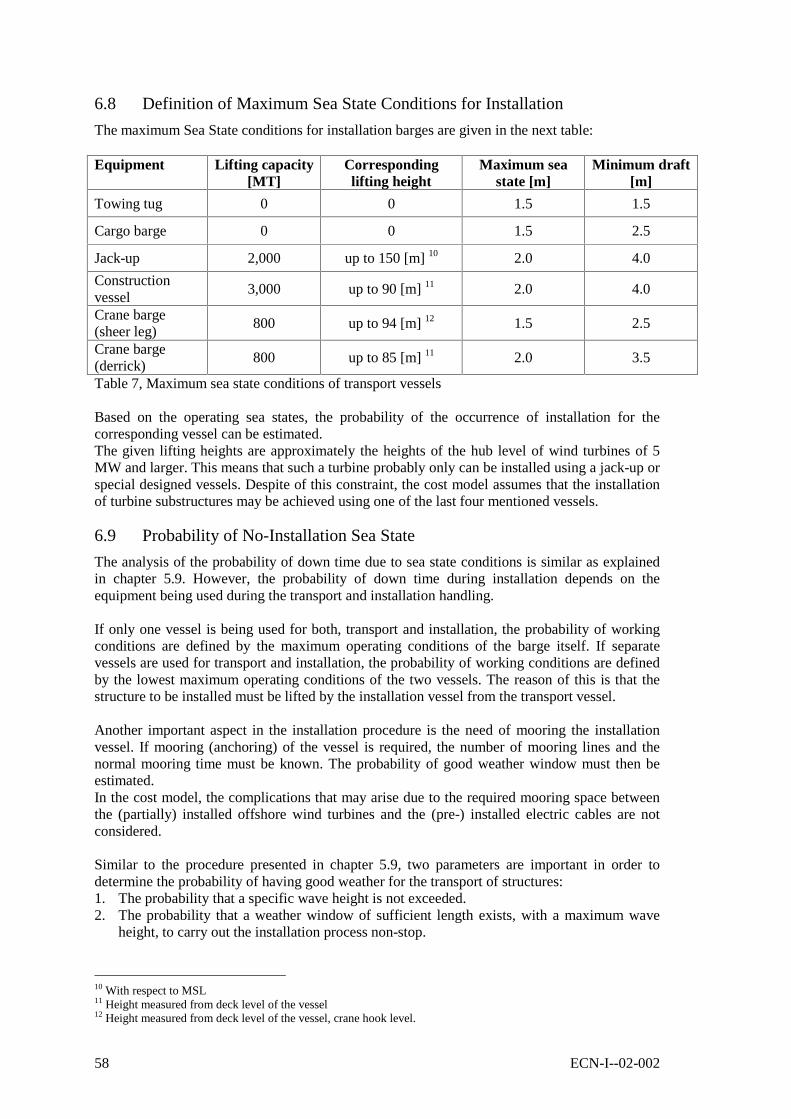
58 ECN-I--02-002
6.8 Definition of Maximum Sea State Conditions for Installation
The maximum Sea State conditions for installation barges are given in the next table:
Equipment Lifting capacity[MT]
Correspondinglifting height
Maximum seastate [m]
Minimum draft[m]
Towing tug 0 0 1.5 1.5
Cargo barge 0 0 1.5 2.5
Jack-up 2,000 up to 150 [m] 10 2.0 4.0
Constructionvessel
3,000 up to 90 [m] 11 2.0 4.0
Crane barge(sheer leg)
800 up to 94 [m] 12 1.5 2.5
Crane barge(derrick)
800 up to 85 [m] 11 2.0 3.5
Table 7, Maximum sea state conditions of transport vessels
Based on the operating sea states, the probability of the occurrence of installation for thecorresponding vessel can be estimated.The given lifting heights are approximately the heights of the hub level of wind turbines of 5MW and larger. This means that such a turbine probably only can be installed using a jack-up orspecial designed vessels. Despite of this constraint, the cost model assumes that the installationof turbine substructures may be achieved using one of the last four mentioned vessels.
6.9 Probability of No-Installation Sea State
The analysis of the probability of down time due to sea state conditions is similar as explainedin chapter 5.9. However, the probability of down time during installation depends on theequipment being used during the transport and installation handling.
If only one vessel is being used for both, transport and installation, the probability of workingconditions are defined by the maximum operating conditions of the barge itself. If separatevessels are used for transport and installation, the probability of working conditions are definedby the lowest maximum operating conditions of the two vessels. The reason of this is that thestructure to be installed must be lifted by the installation vessel from the transport vessel.
Another important aspect in the installation procedure is the need of mooring the installationvessel. If mooring (anchoring) of the vessel is required, the number of mooring lines and thenormal mooring time must be known. The probability of good weather window must then beestimated.In the cost model, the complications that may arise due to the required mooring space betweenthe (partially) installed offshore wind turbines and the (pre-) installed electric cables are notconsidered.
Similar to the procedure presented in chapter 5.9, two parameters are important in order todetermine the probability of having good weather for the transport of structures:1. The probability that a specific wave height is not exceeded.2. The probability that a weather window of sufficient length exists, with a maximum wave
height, to carry out the installation process non-stop.
10 With respect to MSL11 Height measured from deck level of the vessel12 Height measured from deck level of the vessel, crane hook level.

ECN-I--02-002 59
Once these two probabilities are found, the probability of installing the structure at its offshorelocation is found by multiplication, i.e.:Equation 15
)(*)()( benignPHHPinstallP ref≤=
H = wave height [m]Href = reference wave height [m]P(benign) = probability of occurrence of a minimum window
length needed for installation[-]
The total installation time due to bad-weather may then be calculated as follows:Equation 16
)(t total workP
ttt work
delaywork =+=
For installation vessels, the only parameter that counts in the decision of travelling or not is theSea State, i.e. the probability that a specific wave height is exceeded. Neither the wavedirection, nor the influence of wind and current (load or direction) are relevant. Very strongwinds always are correlated to high waves.
The probability of exceeding a wave height at a given location and the probability of occurrenceof a good-weather window are derived in 0. For simplicity, in the cost model it is assumed thatthe probability of occurrence of a good-weather window is equal for any case to 70%. With theformulas derived in 0, the cost model may be improved in the future.
6.10 Estimation of Installation Costs
The analysis of the transport costs including bad weather conditions, has been presented alreadyin section 5.10. Similar to these results, the installation costs are given by the next equation:Equation 17
QtworkP
tMobCost FIXED
work *])(
[1 ++=
For installation cost analysis purposes, in the equation above P(work) must be substituted byP(install). In the equation above, the parameter twork represents the time (in days) required toinstall one structure using one vessel. Note that in the equation the fixed time tFIXED is addedcompared with Equation 10 of section 5.10 and in accordance to section 6.7. This extra time isneeded to load the structure onto the vessel, to position / moor along the wind turbine to beinstalled and to mobilise to the harbour or to the next location. Barges that uses the DP principle(DP = Dynamic Positioning), do not need to moor and therefore they would use less time forinstallation. It is not known to the author of this report if large installation barges have thispositioning system. This possibility is therefore not included into the cost model.
If we now consider the maximum number of structures of the same type to be installed in oneday by the same vessel (Nday, units [1/day]), and the maximum number of structures to betransported at once (Nsim, units [-]), the installation costs of 100 structures becomes:Equation 18
MobQtN
N
PNCost FIXED
day
sim
sim
++= *]*1
[*100
100
Note that if 3 days are required to install one structure and two structures may be transported inone embarkation, the parameter Nsim/Nday = 2/3 [units/day]. The probability P = P(install) isrelated to the number of days required to achieve the installation.

60 ECN-I--02-002
6.11 Combined Transport and Installation
Installation barges could also be used to transport the structures to the site. If that is the case, themobilisation cost of the installation equipment is avoided. The time required to install astructure is however independent from the transport time, even if more structures are transportedat the same time. In this way, the installation costs based on the time required for installationmay be estimated independently.
In this case, the algorithm used to estimate the installation cost of 100 structures is given by:Equation 19
MobQtN
Nt
PNCost instFIXED
combday
simtrFIXED
sim
+
++= **
1*
100_
__100
The mobilisation costs remain unchanged with respect to the previous equation because no extravessels must be mobilised.
The parameter Nday_comb equals to the minimum between Nday_tr and Nday_inst because one vesselmay not transport more structures to their final location without installing them.
In the above equation is P = P(work), the probability that the vessel may realise its operation,transport or installation. In the cost model the lowest probability P, P(transport) or P(install), ischosen. Note that not any vessel is adequate for transport and installation of offshore windturbines.
6.12 The Use of Several Installation Vessels Simultaneously
If several installation vessels are used simultaneously, the derived algorithm must be modifiedwith the number of vessels used. The use of several installation vessels implies the use ofseveral transport vessels as well. Optimised combination of number of transport and number ofinstallation vessels are not included in the cost model.
In the case that the vessel are used only for installation purposes, the cost of installing 100structures using several vessels (Nvess, units [-]) is given by:Equation 20, installation costs.
MobNQtN
N
PNCost
MobNQNtN
N
PNNCost
instvessinstFIXEDinstday
sim
sim
vessvessinstFIXEDinstday
sim
vesssim
**]*1
[*100
***]*1
[**
100
___
100
__
100
++=⇒
++=
It can be seen, that the number of vessels used only influences the mobilisation costs.
In the case of using the same vessel for the transport and for the installation, the equationbecomes:Equation 21, combined costs of transport and installation.
MobNQttN
N
PNCost vessinstFIXEDtrFIXED
combday
sim
sim
**][*1
*100
___
100 +++=
For combined transport and installation the parameters Nvess and Nday_comb are defined as follows:Nvess = Nvess_tr = Nvess_inst
Nday_comb = min(Nday_inst ; Nday_tr)
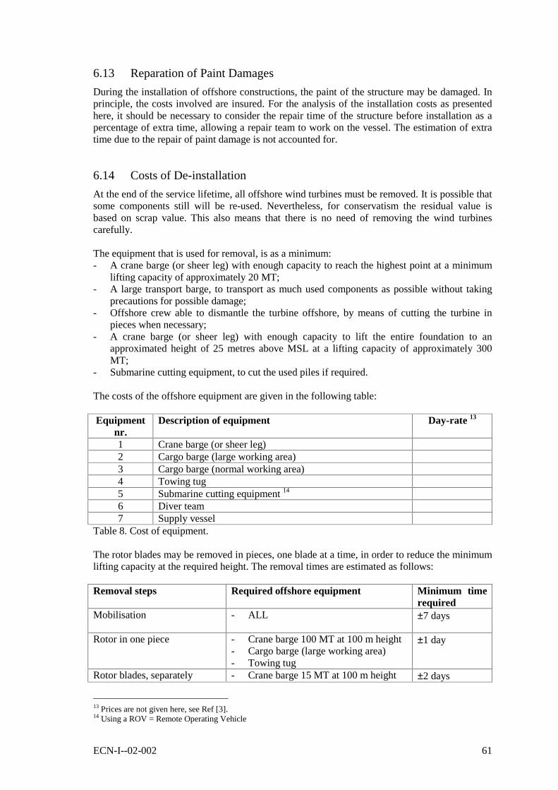
ECN-I--02-002 61
6.13 Reparation of Paint Damages
During the installation of offshore constructions, the paint of the structure may be damaged. Inprinciple, the costs involved are insured. For the analysis of the installation costs as presentedhere, it should be necessary to consider the repair time of the structure before installation as apercentage of extra time, allowing a repair team to work on the vessel. The estimation of extratime due to the repair of paint damage is not accounted for.
6.14 Costs of De-installation
At the end of the service lifetime, all offshore wind turbines must be removed. It is possible thatsome components still will be re-used. Nevertheless, for conservatism the residual value isbased on scrap value. This also means that there is no need of removing the wind turbinescarefully.
The equipment that is used for removal, is as a minimum:- A crane barge (or sheer leg) with enough capacity to reach the highest point at a minimum
lifting capacity of approximately 20 MT;- A large transport barge, to transport as much used components as possible without taking
precautions for possible damage;- Offshore crew able to dismantle the turbine offshore, by means of cutting the turbine in
pieces when necessary;- A crane barge (or sheer leg) with enough capacity to lift the entire foundation to an
approximated height of 25 metres above MSL at a lifting capacity of approximately 300MT;
- Submarine cutting equipment, to cut the used piles if required.
The costs of the offshore equipment are given in the following table:
Equipmentnr.
Description of equipment Day-rate 13
1 Crane barge (or sheer leg)2 Cargo barge (large working area)3 Cargo barge (normal working area)4 Towing tug5 Submarine cutting equipment 14
6 Diver team7 Supply vessel
Table 8. Cost of equipment.
The rotor blades may be removed in pieces, one blade at a time, in order to reduce the minimumlifting capacity at the required height. The removal times are estimated as follows:
Removal steps Required offshore equipment Minimum timerequired
Mobilisation - ALL ±7 days
Rotor in one piece - Crane barge 100 MT at 100 m height- Cargo barge (large working area)- Towing tug
±1 day
Rotor blades, separately - Crane barge 15 MT at 100 m height ±2 days
13 Prices are not given here, see Ref [3].14 Using a ROV = Remote Operating Vehicle

62 ECN-I--02-002
Removal steps Required offshore equipment Minimum timerequired
- Cargo barge- Towing tug
Nacelle in one piece - Crane barge 300 MT at 100 m height- Cargo barge- Towing tug
±1 day
Nacelle in components - Crane barge 50 MT at 100 m height- Cargo barge- Towing tug
±7 days
Tower in one piece - Crane barge 250 MT at 100 m height- Cargo barge- Towing tug
±1 day
Tower in pieces - Crane barge (250 MT divided bynumber of pieces) at 100 m height
- Cargo barge- Towing tug
±1 day/piece
Foundation piles (includesmonopod foundation)
- Submarine cutting equipment- Supply vessel + crew- Diver team- Cargo barge- Towing tug
±2 days/pile
Foundation (jackets or gravitybase)
- Crane barge 300 MT at 25 m height- Cargo barge- Towing tug
±1 day
Demobilisation - ALL ±7 days
Table 9. De-installation of structures.
The costs of the removal of one offshore wind turbine are derived here below, based on thefollowing assumptions:- There is a crane barge with capacity of 300 MT at 100 m height;- The wind turbine has a monopod as foundation;- The rotor, nacelle, tower and foundation are removed separately, but each of them in one
piece;- There are no delays in time due to bad weather conditions.
Removal steps Required equipment Required time 15
Mobilisation - ALL ±7 days
Removal of rotor - Crane barge- Cargo barge (large working area)- Towing tug
±1 day
Removal of nacelle - Crane barge- Cargo barge (normal working area)- Towing tug
±1 day
Removal of tower inone piece
- Crane barge- Cargo barge (normal working area)- Towing tug
±1 day
Cutting-off monopodfoundation
- Submarine cutting equipment 16
- Diver team±2 days
15 Mobilisation not included.16 Using a ROV = Remote Operating Vehicle

ECN-I--02-002 63
- Supply vesselRemoval of foundation - Crane barge
- Cargo barge (normal working area)- Towing tug
±1 day
Demobilisation - ALL ±7 days
It is assumed that all turbine components are loaded onto a cargo barge and when the wholeturbine is removed, the cargo barge travels to the shore. When the use of several offshoreequipment simultaneously is preferred, the cargo barges may be loaded more effectively.
Based on above day-rates and time of operation, the demobilisation costs are calculated. In thiscalculation, the probability of benign weather condition has already been included. Thisprobability is related to a weather window of two days, because the shortest activity takes atleast one day to be realised.If bad weather does not allow continuing with the removal works, the vessel just has to waituntil it can continue its work. This delay has not been taken into account.
6.15 Costs of Installation of a Helicopter Platform
The costs of installation of a helicopter platform are not considered separately. In the cost modelis assumed that these costs are included into the installation costs of a nacelle.
6.16 Cost of Soil Research
The costs of soil research should be added to the overall installation costs or they should beconsidered in the pre-design phase.Soil research includes an investigation of the soil type up to penetration depth and the chance ofearly refusal. This research requires sound analysis. The offshore companies will need theseresults to estimate their installation time, required equipment and thus estimating their overallcosts.
The costs depend on the number of points to be researched. For a squared area of say 100 km2,one measurement at each corner of the area plus one in the middle would satisfy. In this report,7 measurement points are considered. This applies for an area of any shape, but it is restricted toapproximately 100 km2. The time and costs involved into soil research are approximated by theformulas:Equation 22
][*
][*32
kEurospQMobCost
dayspTime
+=+=
In the above formulas is Mob = XXX 17 [k @4 ;;;18 [k @DQGS QXPEHURISRLQWVWREHinvestigated. The estimate for seven points where soil research is needed gives 23 days durationat 400 k WRWDO
6.17 Cost of Scour Protection
A scour hole will develop at the base of the pile foundation, if a threshold current speed at thatlevel is locally exceeded. The threshold current speed depends on the seabed material. While thescour hole deepens, the current speed decreases. An equilibrium point is reached at a certainmaximum depth. If the threshold current speed is exceeded globally, the scour hole will bepartially filled by seabed particles that are in suspension at that level.
17 Prices are not given here, see Ref [3].18 Prices are not given here, see Ref [3].

64 ECN-I--02-002
For a jacket structure like a tripod, there are two types of scour holes that will develop inabsence of protection:a) A local scour hole around each leg of the structure;b) A global scour deepness around the whole structure. This global deepness will be relatively
less severe than the local scour hole.
Based on a case study for the DOWEC project (reference [14]), a maximum scour hole may bedetermined given a pile diameter, current speed and seabed material. The results show that ascour hole with a depth of approximately two times the pile diameter would develop if no scourprotection were used.For the scour protection of a gravity base or of a jacket, there is no rule of thumb that can beused. For this reason the dimensions of the scour protection of these structures is based on thetower diameter of the turbine in a similar way as for a monopod foundation.
For the cost model as presented here, a scour protection is included, based on the assumptionthat otherwise a scour hole will develop without the protection. The estimation of the costs isbased on that derived in the DOWEC project, and it is resumed here.
Scour protection characteristics (reference [14]):- Protection on top of seabed, no dredging required.- Radius of scour protection equals 6x pile diameter in every direction excluding slope
extension- Slope at the end of scour protection is 3:1 (extension equals to 3x depth total layer)- 3 rock layers
- top layer: rock diameter, Dn,50 = 0.45 m, 0.9 m layer thickness- filter layer 1: rock diameter, Dn,50 = 0.08 m, 0.3 m layer thickness- filter layer 2: rock diameter, Dn,50 = 0.01 m, 0.3 m layer thickness
- Total rock quantity 6500 MT for each unit for 25 m diameter of scour protection- A side stone dumping vessel is used for the operation with a loading capacity of 980 MT.
Based on the referred scour protection characteristics, the following correspondingcharacteristics are considered in the cost model:- Protection on top of seabed, no dredging required.- Radius of scour protection equals 6x pile diameter plus 3x depth total layer- 3 rock layers, total layer depth equals 1.5 metres- Required scour protection rock quantity 10.5 MT/m2
- A side stone dumping vessel is used for the operation
The realisation of scour protection is assumed to be applied immediately after the installation ofthe pile foundation is achieved, giving no time to the seabed to develop a scour hole.
Scour protection costs are sub-divided into mobilisation and demobilisation costs of offshoreequipment and material costs. Mobilisation and demobilisation costs are appointed every timethe scour protection may not be realised in a continuous operation. These costs are presented inreference [14] as follows (prices referred to year 2000):
Mobilisation and demobilisation costs: Mob = XXX per occurrence 19
Operational day-rate of stone vessel: Q = XXX per day 20
Costs of rock material rocksprice = XXX [ 07@21
In the cost model the costs for scour protection, using one vessel, are estimated by:
19 Prices are not given here, see Ref [3].20 Prices are not given here, see Ref [3].21 Prices are not given here, see Ref [3].

ECN-I--02-002 65
Equation 23
workrocksscour tQMobCostCost *++=In this formula Costrock represents the material costs. The parameter twork represents the totaltime in days, that the stone dumping vessel must be operational.Equation 24
][24
1*_
_
*2
__
daystimeloadingspeedvessel
Dshoret
timeloadingtimetravelt
work
work
+=⇒
+=
The parameter Dshore represents the distance between the farm and the harbour on the shorewhere the stones are loaded onto the vessel. The loading_time parameter is vessel specific. Inthe cost model, this parameter is set to 3.5 hours.
The material costs are given by:Equation 25
( ) pricerocksrocksrocks rocksVCost ** ρ=
In the above formula, the density of the rock material is approximated by ρrocks §>07P3]
Finally, the volume of rocks needed is approximated by the next formula:Equation 26
( ) layerpilelayerrocksrocks tLtRV *)35tan(****202 ππ ≈=
Lpile [m] = length of the pile in the seabedtlayer [m] = thickness of scour protection layer, §>P@
Because the scour protection work may be realised while other wind turbines are installed atother locations within the wind farm, the overall time involved in the application of the scourprotection is not considered in the model.For planning considerations it must be observed that, during the application time of scourprotection, no other installation operation may be realised to the same unit, i.e. the installationsequence is supposed to be:- install foundation (if applicable);- apply scour protection;- install other components of wind turbine (not applicable for configuration 8);- install cabling.
6.18 Cost of Cable Installation
The number of submarine cables present in the wind farm depends on the type of current to bedelivered at the connection point on the shore.
The number of electric cables present between the transformer station and the shore when ACcurrent is considered (3-phase HVAC) needs to be input by the user of the cost model. Further itis assumed that the cables do not lay together to avoid electromagnetic interference and tominimise the risk of damage by anchors of vessels. This means that the installation of threeelectric cables will take three times longer than the installation of one cable and that theinstallation costs will be about three times higher.
In addition, it is assumed that for DC current only one cable is required between the transformerstation and the shore. No redundancy is assumed.
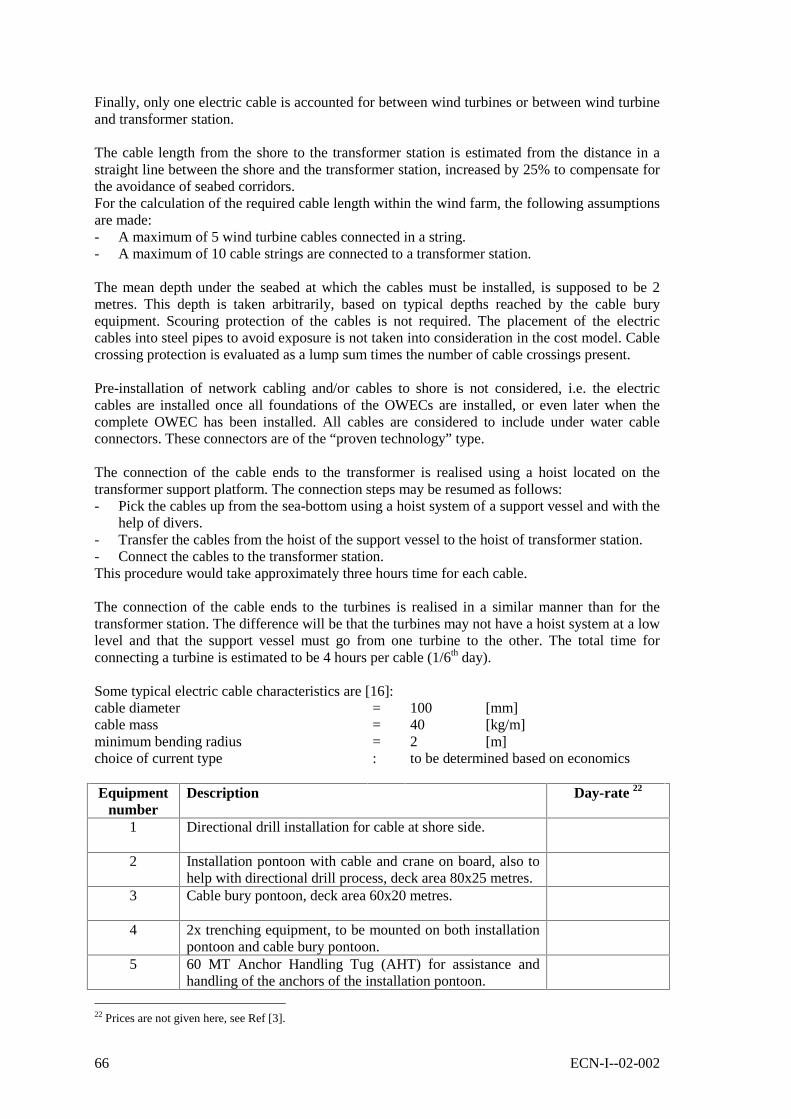
66 ECN-I--02-002
Finally, only one electric cable is accounted for between wind turbines or between wind turbineand transformer station.
The cable length from the shore to the transformer station is estimated from the distance in astraight line between the shore and the transformer station, increased by 25% to compensate forthe avoidance of seabed corridors.For the calculation of the required cable length within the wind farm, the following assumptionsare made:- A maximum of 5 wind turbine cables connected in a string.- A maximum of 10 cable strings are connected to a transformer station.
The mean depth under the seabed at which the cables must be installed, is supposed to be 2metres. This depth is taken arbitrarily, based on typical depths reached by the cable buryequipment. Scouring protection of the cables is not required. The placement of the electriccables into steel pipes to avoid exposure is not taken into consideration in the cost model. Cablecrossing protection is evaluated as a lump sum times the number of cable crossings present.
Pre-installation of network cabling and/or cables to shore is not considered, i.e. the electriccables are installed once all foundations of the OWECs are installed, or even later when thecomplete OWEC has been installed. All cables are considered to include under water cableconnectors. These connectors are of the “proven technology” type.
The connection of the cable ends to the transformer is realised using a hoist located on thetransformer support platform. The connection steps may be resumed as follows:- Pick the cables up from the sea-bottom using a hoist system of a support vessel and with the
help of divers.- Transfer the cables from the hoist of the support vessel to the hoist of transformer station.- Connect the cables to the transformer station.This procedure would take approximately three hours time for each cable.
The connection of the cable ends to the turbines is realised in a similar manner than for thetransformer station. The difference will be that the turbines may not have a hoist system at a lowlevel and that the support vessel must go from one turbine to the other. The total time forconnecting a turbine is estimated to be 4 hours per cable (1/6th day).
Some typical electric cable characteristics are [16]:cable diameter = 100 [mm]cable mass = 40 [kg/m]minimum bending radius = 2 [m]choice of current type : to be determined based on economics
Equipmentnumber
Description Day-rate 22
1 Directional drill installation for cable at shore side.
2 Installation pontoon with cable and crane on board, also tohelp with directional drill process, deck area 80x25 metres.
3 Cable bury pontoon, deck area 60x20 metres.
4 2x trenching equipment, to be mounted on both installationpontoon and cable bury pontoon.
5 60 MT Anchor Handling Tug (AHT) for assistance andhandling of the anchors of the installation pontoon.
22 Prices are not given here, see Ref [3].
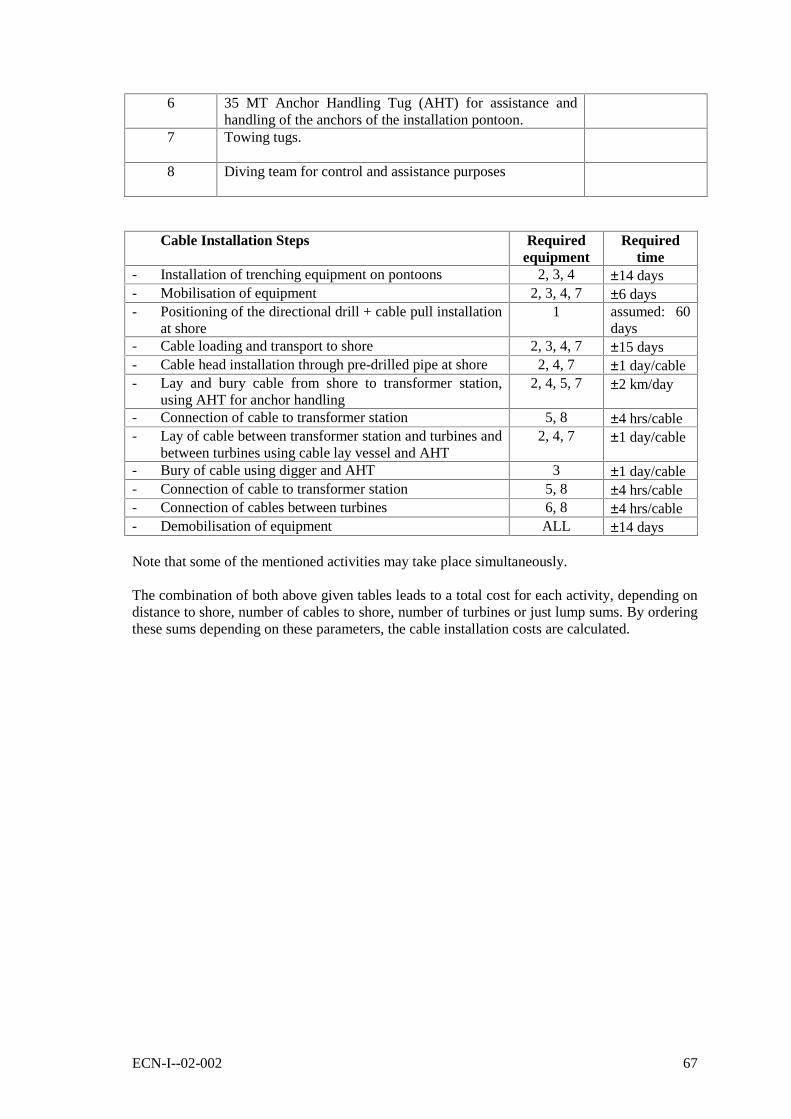
ECN-I--02-002 67
6 35 MT Anchor Handling Tug (AHT) for assistance andhandling of the anchors of the installation pontoon.
7 Towing tugs.
8 Diving team for control and assistance purposes
Cable Installation Steps Requiredequipment
Requiredtime
- Installation of trenching equipment on pontoons 2, 3, 4 ±14 days- Mobilisation of equipment 2, 3, 4, 7 ±6 days- Positioning of the directional drill + cable pull installation
at shore1 assumed: 60
days- Cable loading and transport to shore 2, 3, 4, 7 ±15 days- Cable head installation through pre-drilled pipe at shore 2, 4, 7 ±1 day/cable- Lay and bury cable from shore to transformer station,
using AHT for anchor handling2, 4, 5, 7 ±2 km/day
- Connection of cable to transformer station 5, 8 ±4 hrs/cable- Lay of cable between transformer station and turbines and
between turbines using cable lay vessel and AHT2, 4, 7 ±1 day/cable
- Bury of cable using digger and AHT 3 ±1 day/cable- Connection of cable to transformer station 5, 8 ±4 hrs/cable- Connection of cables between turbines 6, 8 ±4 hrs/cable- Demobilisation of equipment ALL ±14 days
Note that some of the mentioned activities may take place simultaneously.
The combination of both above given tables leads to a total cost for each activity, depending ondistance to shore, number of cables to shore, number of turbines or just lump sums. By orderingthese sums depending on these parameters, the cable installation costs are calculated.

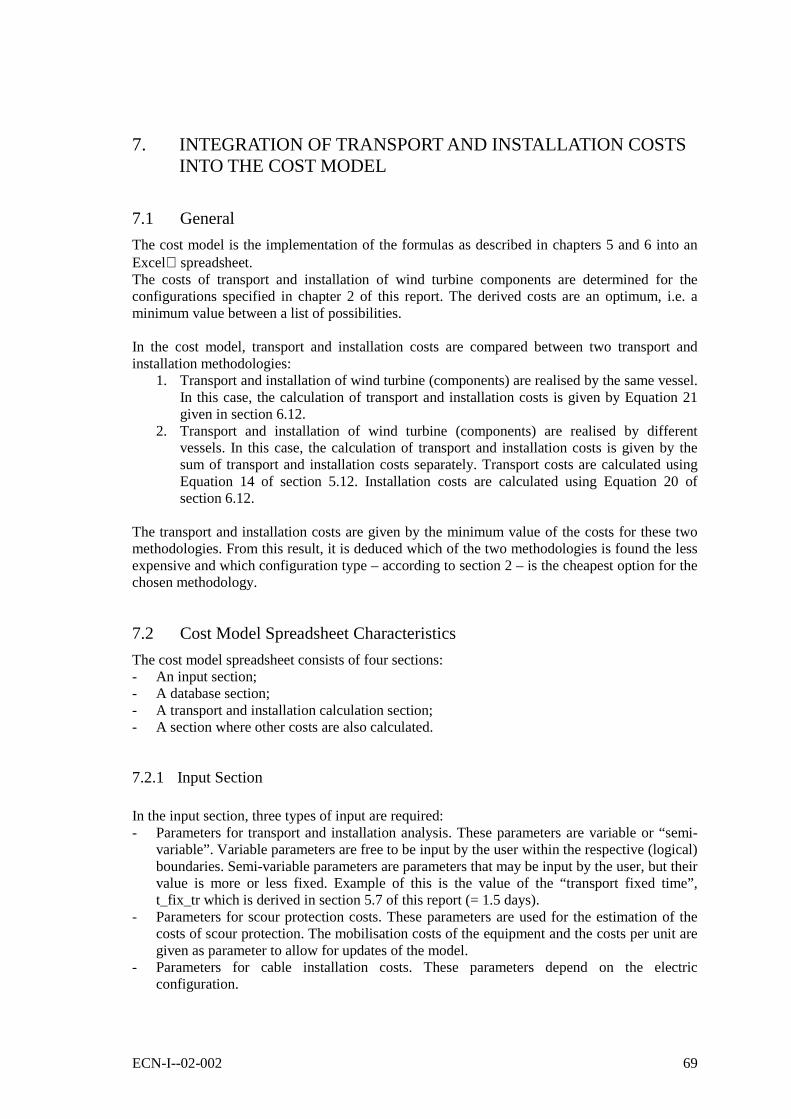
ECN-I--02-002 69
7. INTEGRATION OF TRANSPORT AND INSTALLATION COSTSINTO THE COST MODEL
7.1 General
The cost model is the implementation of the formulas as described in chapters 5 and 6 into anExcel spreadsheet.The costs of transport and installation of wind turbine components are determined for theconfigurations specified in chapter 2 of this report. The derived costs are an optimum, i.e. aminimum value between a list of possibilities.
In the cost model, transport and installation costs are compared between two transport andinstallation methodologies:
1. Transport and installation of wind turbine (components) are realised by the same vessel.In this case, the calculation of transport and installation costs is given by Equation 21given in section 6.12.
2. Transport and installation of wind turbine (components) are realised by differentvessels. In this case, the calculation of transport and installation costs is given by thesum of transport and installation costs separately. Transport costs are calculated usingEquation 14 of section 5.12. Installation costs are calculated using Equation 20 ofsection 6.12.
The transport and installation costs are given by the minimum value of the costs for these twomethodologies. From this result, it is deduced which of the two methodologies is found the lessexpensive and which configuration type – according to section 2 – is the cheapest option for thechosen methodology.
7.2 Cost Model Spreadsheet Characteristics
The cost model spreadsheet consists of four sections:- An input section;- A database section;- A transport and installation calculation section;- A section where other costs are also calculated.
7.2.1 Input Section
In the input section, three types of input are required:- Parameters for transport and installation analysis. These parameters are variable or “semi-
variable”. Variable parameters are free to be input by the user within the respective (logical)boundaries. Semi-variable parameters are parameters that may be input by the user, but theirvalue is more or less fixed. Example of this is the value of the “transport fixed time”,t_fix_tr which is derived in section 5.7 of this report (= 1.5 days).
- Parameters for scour protection costs. These parameters are used for the estimation of thecosts of scour protection. The mobilisation costs of the equipment and the costs per unit aregiven as parameter to allow for updates of the model.
- Parameters for cable installation costs. These parameters depend on the electricconfiguration.
70 ECN-I--02-002
The input section of the spreadsheet is shown in the next figure:
Probability of good weather for transport P(benign)_tr 0.7 [-]Probability of good weather for installation P(benign)_inst 0.75 [-]Number of turbines in wind farm Nowec 100 [-]Number of vessels used for transport Nvess_tr 1 [-]Number of vessels used for installation Nvess_inst 1 [-]Weibull shape factor for wave height Kweibull 2 [-]Weibull scale factor for wave height Cweibull 1.6 [-]Transport "fixed" time between turbines t_fix_tr 1.5 [days]Installation "fixed" time between turbines t_fix_inst 2 [days]
Fundatie type Monopod 4
Diameter of turbine tower d_tower 4.5 [m]Mob en demob costs of equipment Mob_scour 165,000 [ ]Installation costs per unit (per 6500 MT) Q_scour 375,000 [ ]
Number of electric cables to shore Ncable 1 [-]Number of turbines in a cluster Ncluster 10 [-]Distance of Wind Farm to shore Dshore 40 [km]Number of cable crossings (cable to shore) Ncross 3 [-]
PARAMETERS FOR TRANSPORT AND INSTALLATION ANALYSIS
PARAMETERS FOR SCOUR PROTECTION COSTS
PARAMETERS FOR CABLE INSTALLATION COSTS
Figure 16
7.2.2 Database Section
The database section of the spreadsheet is a compilation of the following tables:- Table 3, Cost of transport equipment (section 5.6);- Table 4, Transport of turbine substructures (section 5.7);- Table 5, Maximum sea state conditions of transport vessels (section 5.8 - only the given
maximum sea state where the vessels are operational);- Table 6, Installation of turbine substructures;- Table 7, Maximum sea state conditions of transport vessels (only the given maximum sea
state where the vessels are operational).
7.2.3 Transport and Installation Calculation Section
In the transport and installation section, the costs for transport and installation as presented inchapters 5 and 6 are calculated. The costs are the minimum costs of the two methodologies asexplained before. Four calculations are made:- Calculation of transport costs alone, according to Equation 14 of section 5.12;- Calculation of installation costs alone, according to Equation 20 of section 6.12;- Calculation of transport and installation costs together when using vessels for the combined
operation, according to Equation 21 of section 6.12;- Calculation of transport and installation costs separately, when using different vessels for
each operation. These costs are equal to the sum of the first two mentioned calculations.

ECN-I--02-002 71
The overall calculation of Transport and Installation costs is explained using the followingdiagram:
Calculationof
combinedTransport
andInstallation
Calculationof
Transportcosts
separately
Calculationof
Installationcosts
separately
Component nr 1
Component nr 3
Component nr 2
Component nr N
TRANSPORT INSTALLATION COMBINED T&I
Config nr 1Config nr 2
Config nr 8
Configurationprice
Configurationprice
Configurationprice
Price of separatedTransport and Installation
for each configuration
Minimum pricefor
Transport and Installation
Config nr 1Config nr 2
Config nr 8
Price of Transportand Installation
Configurationnumber / type
Figure 17. Diagram of calculation of overall Transport and Installation costs.
Given the presented configurations of section 2, the following wind turbine components /assemblies are defined:- Wind turbine foundation- Wind turbine tower- Wind turbine nacelle

72 ECN-I--02-002
- Wind turbine rotor- Guyed turbine (it assumes small monopod foundation)- Tower and nacelle assembly- Rotor and nacelle assembly- Foundation and tower assembly- Foundation, tower and nacelle assembly- Tower, nacelle and rotor assembly- Complete OWEC
For each of these components, the transport costs, installation costs and combined costs oftransport and installation using the same vessels are calculated considering the available vessels.
Based on the calculated costs of transport and installation of the components, the transport andinstallation costs of the configurations are determined. The costs of separated transport andinstallation (using different vessels) are found by adding these costs to each other.
From the obtained costs, a minimum is obtained by comparison. The result allows also todetermine which configuration type is the most cost effective.
Transport Costs
The calculation of the transport costs alone is explained using the diagram of Figure 18.From the input sheet three parameters are taken: Pbenign_tr and the shape and scale factors ofthe Weibull distribution of waves: kweibull and cweibull. With these three parameters, theprobability of transport is calculated.For each wind turbine component / assembly, the transport costs are calculated consideringevery vessel available. The parameters Nsim_tr and Nday_tr give an indication if the transportusing those vessels is possible or not (Nsim_tr = 0 means that the vessel cannot transport acomponent of this type and Nday_tr = 0 means that no component of that type can betransported to the location in one day).If the parameters Nsim_tr or Nday_tr are equal to zero, a very large transport cost value (faultvalue) is obtained. This fault value is needed because the optimisation procedure searches forthe minimum costs of transport between a number of possibilities.
The last step in the calculation is to verify if the foundation type as specified by the user equalsto the foundation of the database from which the transport costs are derived. If that’s not thecase an extra parameter gets the value zero. From the analysis of the multiplication of thisparameter and the value of transport costs for the determined vessel and turbine component, theactual costs of transport or a fault value is determined.
The optimum is found by comparison of transport costs for all configurations.
Installation Costs
The diagram of Figure 19 illustrates the calculation of the installation costs alone. Thiscalculation is similar to the one for the transport costs.From the input sheet, the wave parameters are taken. With these parameters, the probability ofinstallation is calculated.For each wind turbine component / assembly, the installation costs are calculated consideringevery vessel available, on a similar way as presented at the transport costs calculation: theparameters Nsim_tr and Nday_inst give an indication if the installation using those vessels ispossible or not.If the parameters Nsim_tr or Nday_inst are equal to zero, the ‘provisory’ installation costs arezero. The difference with the transport costs calculation is that the combined costs of transportand installation are derived partially from this result.

ECN-I--02-002 73
The last step in the calculation is to verify if the foundation type as specified by the user equalsto the foundation of the database from which the installation costs are derived. If that’s not thecase an extra parameter gets the value zero. From the analysis of the multiplication of thisparameter and the value of installation costs for the determined vessel and turbine component,the actual costs of installation or a fault value is determined. This fault value is needed becausethe optimisation procedure searches for the minimum costs of transport between a number ofpossibilities.
The optimum is found by comparison of transport costs for all configurations.
Provisional transport Costs
Nsim_tr & Nday_tr ≠ 0 ?
Fault valueTransport Costs
=Eq.14 of §5.13
P(transport),Eq.5 of §5.10
INPUT
DATABASE
YES NO
Pbenign,Cweibull,Kweibull
Nowec,t_fix_tr,
Nvess_tr
TRANSPORT COSTS
Foundation considered =foundation type of the
database?
value=1 value=0
yes no
(Transport costs)*(value) ≠ 0 ?
TRANSPORT COSTS Fault value
YES NO
transportcosts
value
Foundation_type
Hs_vessel
Nsim_tr,Nday_tr,Mob, Q
Figure 18. Transport costs diagram.

74 ECN-I--02-002
Provisory installation Costs
Nsim_tr & Nday_tr ≠ 0 ?
costs = 0Installation costs
=Eq.21 of §6.12
P(installation),Eq.15 of §6.9
INPUT
DATABASE
YES NO
Pbenign,Cweibull,Kweibull
Nowec,t_fix_inst,
Nvess_inst
INSTALLATION COSTS
Foundation considered =foundation type of the
database?
value=1 value=0
yes no
(Installation cost)*(value) ≠ 0 ?
INSTALLATION COSTS Fault value
YES
value
Foundation_type
Hs_vessel
Nsim_tr,Nday_inst,
Mob, Q
installationcosts
NO
Figure 19. Installation costs diagram.
Costs of Combined Transport and Installation
The calculation of the costs of combined transport and installation are very similar to theprocedures as explained above. The diagram is almost identical (see Figure 20), only thedifferences will be explained here.- The parameter Nday_comb represents the number of structures that the vessel may transport
or install in one day. Because the same vessel is used for both operations, the value of thisparameter is obtained from the minimum of these values for transport and installationseparately.
- The probability of install / transport a turbine component is also determined as the minimumof these values for transport and installation separately, because the probability parametergives an indication of the workability of the vessel independent of the use of the vessel.

ECN-I--02-002 75
Provisional combined Costs
Nsim_tr & Nday_comb ≠ 0 ?
costs = 0combined costs
=Eq.22 of §6.12
P(work)=MIN(Pinst;Ptr)
INPUT
DATABASE
YESNday_comb
NO
CweibullKweibull
Nowec,t_fix_inst,
MIN(Nvess_inst;Nvess_tr)
TRANSPORT and INSTALLATION COSTS USING THE SAME VESSELS
Foundation considered =foundation type of the
database?
value=1 value=0
yes no
(combined costs)*(value) ≠ 0 ?
COMBINED COSTSof T&I
Fault value
YES NO
combinedcosts
oftransport
andinstallation
value
Foundation_type
Hs_vessel
Nsim_tr,Mob, Q
Nday_comb = MIN(Nday_tr ; Nday_inst)
Nday_inst’Nday_tr
Figure 20. Diagram of the calculation of combined transport and installation.
7.2.4 Other Calculations SectionIn the last section of the cost model, other calculations are realised. These are:- Calculation of the scour protection costs. This calculation is done by means of an empirical
formula derived from data of an offshore company specialised in this area. The formulaused is given by Equation 23 of section 6.17.
- Calculation of costs of soil research. This calculation is done by means of an empiricalformula derived from data of an offshore consultant. The formula used is given by Equation22 of section 6.16.

76 ECN-I--02-002
- Calculation of cable installation costs. This calculation is done by means of a matrixcombination of steps and installation equipment against equipment costs. The procedureused has been explained in section 6.18.
- Calculation of de-installation costs. This calculation is done by means of a matrixcombination of removal steps and required offshore equipment against equipment costs.The procedure used has been explained in section 6.14.

ECN-I--02-002 77
8. EVALUATION OF RESULTS
8.1 General
In this section, some results obtained with the model costs are presented. The analysis is dividedinto the following:- Costs of transport and installation- Type of transport and installation strategy- Analysis of optimum found configuration- Influence of used parameters into the found transport and installation costs- Influence of used parameters into the found scour protection costs- Influence of used parameters into the found cable installation costs
The results obtained with the cost model have not been verified against existent wind farmconfigurations.
8.2 Transport and Installation Costs
The overall transport and installation costs of OWECs are presented in the next figure:
OWEC Installation - Monopod
0
20
40
60
80
100
120
140
160
180
1 2 5 10 20 50 100 250
Number of Turbines
Inst
alla
tio
n c
ost
s [M
Eu
ros]
Monopod
Tripod
Figure 21. Overall transport and installation costs.
It can be seen that there is no big difference in overall transport and installation costs when amonopod type of foundation is compared with a tripod. The above graph is based on the nexttable of results:
Number of OWECs to be installedCOSTS[M @ 1 2 5 10 20 50 100 250
Monopod basedOWECs
1.3 2.0 4.0 7.1 13.5 32.8 65.0 161.5
Jacket basedOWECs
1.2 1.8 3.5 6.4 12.2 29.7 58.8 146.0

78 ECN-I--02-002
By doubling the number of OWECs to be installed, the overall transport and installation costsare not twice as much. In fact if comparing the above costs on a linear horizontal scale, it can beseen that the overall transport and installation costs increases linearly, see Figure 22:
Installation costs of OWECs
0
20
40
60
80
100
120
50 75 100 125 150
Number of OWECs
Inst
alla
tio
n c
ost
s [M
Eu
ros]
Monopod
Figure 22. Overall transport and installation costs plotted on a linear scale.
Another interesting result, is that the overall transport and installation costs also increaseslinearly with increasing number of transport and installation vessels used, see Figure 23.
Installation costs of 100 OWECs
63.0
64.0
65.0
66.0
67.0
68.0
69.0
70.0
1 2 3 4 5
Number of vessels used
Inst
alla
tion
cost
s[M
Eur
os]
Monopod based OWEC
Figure 23. Cost of transport and installation of 100 wind turbines.
In the above graph, the number of transport vessels used equals the number of installationvessels used. The cost model allows however a distinction between the number of transport andthe number of installation vessels to be given in order to optimise the costs involved.

ECN-I--02-002 79
The distance to the shore has not been taken into effect for the overall transport and installationcosts of the cost model. For reasons of simplicity, it is assumed in the cost model that thetravelling time for transport and installation vessels will not differ significantly if the wind farmis located between 10 and 50 km from shore.
The weather influence on the overall transport and installation costs is given by the Weibullshape and scale parameters (kweibull and cweibull) and by the user-specified probability of benignweather for transport and installation (Pbenign_tr and Pbenign_inst).
The following table presents the influence of the Weibull parameters. They are obtained for awind farm with 100 wind turbines using a monopod as foundation:
WEATHER PARAMETERSCosts in [M @
P(benign)_tr 0.7 0.7 0.7 0.7 0.7 0.7P(benign)_inst 0.75 0.75 0.75 0.75 0.75 0.75Kweibull 1.8 1.9 2 2.1 2.2 2.3Cweibull 1.6 1.6 1.6 1.6 1.6 1.6Overall Costs 66.34 65.99 65.66 65.34 65.03 64.73Variation 1.0% 0.5% 0% -0.5% -1.0% -1.4%P(benign)_tr 0.7 0.7 0.7 0.7 0.7 0.7P(benign)_inst 0.75 0.75 0.75 0.75 0.75 0.75Kweibull 2 2 2 2 2 2Cweibull 1.4 1.5 1.6 1.7 1.8 1.9Overall Costs 61.31 63.35 65.66 68.23 71.04 74.08Variation -6.6% -3.5% 0% 3.9% 8.2% 12.8%
From the table above, it can be noticed that variation of the scale parameter of the Weibulldistribution hardly influences the overall transport and installation costs, while the shapeparameter has a large influence.
In a similar way, the influence of the parameters that represent the probability of a benignweather window for transport and installation vessels, is presented in the next table. Thesevalues are also obtained for a wind farm with 100 wind turbines using a monopod as foundation.
WEATHER PARAMETERSCosts in [M @
P(benign)_tr 0.5 0.6 0.7 0.8 0.9 0.99P(benign)_inst 0.75 0.75 0.75 0.75 0.75 0.75Kweibull 2 2 2 2 2 2Cweibull 1.6 1.6 1.6 1.6 1.6 1.6Overall Costs 67.43 66.00 64.99 64.22 63.63 63.20Variation 4% 2% 0% -1% -2% -3%P(benign)_tr 0.7 0.7 0.7 0.7 0.7 0.7P(benign)_inst 0.50 0.60 0.70 0.80 0.90 0.99Kweibull 2 2 2 2 2 2Cweibull 1.6 1.6 1.6 1.6 1.6 1.6Overall Costs 83.97 74.48 67.70 62.62 58.66 55.77Variation 24% 10% 0% -8% -13% -18%
It can be noticed that a variation of the probability of benign weather window for transportvessels has a minor influence on the overall costs, while the same variation of the probability forthe installation vessels has a very significant influence into these costs. This may be explainedby the fact that installation vessels generally need a relative long time to realise their job, so a

80 ECN-I--02-002
low probability of benign weather window will affect the total number of days necessary toinstall the wind turbine components/assemblies considerably.Note that the probability of transport / installation is not given only to the above parameters, butit is also related to the probability of exceedance of a determined wave height (see for referencealso Equation 5).
8.3 Scour Protection Costs
The scour protection costs obtained with the cost model are plotted in Figure 24, Figure 25 and :
Scour Protection Costs
-
10.0
20.0
30.0
40.0
50.0
1 2 5 10 20 50 100 250
Number of OWECs
Pro
tect
ion
co
sts
[M E
uro
s]
Scour
Figure 24. Scour protection costs.
Scour Protection Costs(linear scale)
-
5.0
10.0
15.0
20.0
25.0
30.0
50 75 100 125 150
Number of OWECs
Pro
tect
ion
co
sts
[M E
uro
s]
Scour
Figure 25. Scour protection costs (linear scale).

ECN-I--02-002 81
Scour Protection Costs(price per OWEC)
-
0.05
0.10
0.15
0.20
0.25
0.30
0.35
0.40
1 2 5 10 20 50 100 250
Number of OWECs
Pro
tect
ion
co
sts
[M E
uro
s]Scour
Figure 26. Scour protection costs, price per OWEC.
The scour protection costs are linear for a fixed diameter of monopod foundation (centralcolumn if tripod). For a variable diameter of monopod, the costs vary quadratically.
Scour Protection Costs(price per OWEC)
0.00
0.10
0.20
0.30
0.40
2 2.5 3 3.5 4 4.5 5
Monopod diameter [m]
Pro
tect
ion
co
sts
[M E
uro
s]
Scour
Figure 27. Scour protection costs, OWECs with variable diameter , price per OWEC

82 ECN-I--02-002
8.4 Cable Installation Costs
The costs of electric cable installation in a wind farm depend heavily on the number of windturbines in the farm. The number of electric cables for electric connection to the grid onshorehas a minor influence on these costs. The following two figures show these relations:
Cable installation costs
-
5.0
10.0
15.0
20.0
25.0
50 75 100 125 150
Number of OWECs
Inst
alla
tio
n c
ost
s [M
Eu
ros]
overall costs
Figure 28. Overall cable installation costs, as function ofthe number of wind turbines present in the farm.
Cable installation costs
15.00
15.50
16.00
16.50
17.00
17.50
18.00
1 2 3 4
Number of cables to shore
Inst
alla
tio
n c
ost
s [M
Eu
ros]
cables to shore
Figure 29. Overall cable installation costs, as function ofthe number of cable connections to shore.
The influence of the number of wind turbines connected in a cluster (Ncluster) and the influenceof the distance between a central point of the wind farm and the shore (Dshore), is presented inthe next table. These results are derived for a wind farm of 100 wind turbines and 1 electriccable for connection to the grid onshore:

ECN-I--02-002 83
Cable Installation CostsNcluster [-] 5 8 10 15 25Dshore [km] 40 40 40 40 40
total costs [M @ 16.79 16.76 16.74 16.73 16.72Variation [-] 0.2% 0.1% 0.0% -0.1% -0.1%Ncluster [-] 10 10 10 10 10Dshore [km] 10 20 30 40 50
total costs [M @ 15.69 16.04 16.39 16.74 17.09Variation [-] -4.3% -2.1% 0.0% 2.1% 4.3%
The influence of these two parameters is considered relatively low.
Finally, the variation in cable installation costs related to the number of cable crossings isneglected. The costs due to these crossings are incorporated into the cost model as a linearfunction depending on the number of crossings to be realised.
8.5 De-Installation Costs
The costs of removal of wind turbine structures after the end of their lifetime, but expressed inactual values, varies approximately linear with the number of wind turbines present in the windfarm. Only when the number of OWECs in the farm are low, the (de-)mobilisation costs play arelatively more important role into the overall de-installation costs.
The results found with the model are presented in the next figure:
0
10
20
30
40
50
60
Costs[M Euros]
10 20 30 40 50 60 70 80 90 100
Number of OWECs
De-installation Costs
De-installation
Figure 30. Costs of removal of OWECs after lifetime.


ECN-I--02-002 85
9. CONCLUSIONS AND RECOMMENDATIONS
9.1 Conclusions
1. The following costs items have been detailed in the OWECOP cost model:- Transport and Installation costs;- Scour protection costs;- Cable lying costs;- Costs of soil research;- Costs of removal of wind turbine (components).
2. For the implementation of transport and installation costs into the model, eight wind turbineinstallation configurations are investigated. These configurations are the result of combiningfour identified main parts of a wind turbine: rotor, nacelle, tower and support structure.For each configuration, the transport and installation costs, using separated vessels or usingone vessel for both activities, are investigated. The cost model searches for an economicoptimum between these configurations. For the activities to be performed during transportand installation, some known offshore equipment is used into the database of the model.
3. The calculation of the transport and installation costs include an estimation of the delay intransport and installation time due to high waves, at which some vessels cannot performtheir activities. The estimation of these delays is based on a Weibull probability distributionof the wave height coupled to the maximum wave height at which the considered vesselmay operate. For the estimation of the time delay, the Weibull variables of the probabilitydistribution are user’s input. Some known values of these variables for the Dutch EEZ arepresented in one of the appendices of this report.
In section 8, some results obtained with the cost model have been presented. Based on theseresults, the following conclusions are drawn:
4. The overall transport and installation costs are assumed not to be influenced by the size ofthe wind turbine components / assemblies. This assumption is of course not entirely correct.In some cases, it is conceivable that the size of the components has almost no influence onthe transport costs.Examples of this are:- The number of monopod foundations to be transported on a barge. When thinking about
the diameters of the foundations, it is possible to transport more foundations on a bargewhen the diameters are relatively smaller. The differences will however be marginal.The length of the monopod foundations could have a strong influence on the chosencargo vessel. However, if it is considered that the foundation will extend beyond thelength limits of the barge, then no big differences in transport prices are to be expected.
- The number of jacket foundations to be transported on a barge. Since it is assumed thatthe jacket foundations would be transported standing, small differences in the numberof structures possible to be transported are expected. Nevertheless, cargo barges wouldtransport one or two jacket foundations more or less independent of their sizes, becausethey would not differ too much from each other for the given megawatt size of the windturbines.
5. The overall transport and installation costs are assumed not to be influenced by the mass ofthe wind turbine components / assemblies. This assumption is of course not correct. Cranecapacity and crane capacity related to the height to be lifted, have a large impact in thechoice of an offshore installation vessel. Nevertheless, it may be assumed that up to a

86 ECN-I--02-002
certain offshore wind turbine size, a standard lifting equipment would be hired at mean day-rate costs. The exact turbine size limit is not known. Based on existent offshore equipmentlike, sheer-leg vessels, the limit would be up to 4 to 5 MW turbine range.
6. The distance to the shore is considered not to be of influence on the overall transport andinstallation costs of the model. For reasons of simplicity, it is assumed in the cost model thatthe travelling time for transport and installation vessels will not differ much if the windfarm is located between 10 and 50 km from shore.If 6 knots (11.11 km/h) is considered as an average travelling speed of a vessel, the actualtravelling time will vary between 1 and 4.5 hours. The time that an offshore company willconsider their vessel ‘travelling’ will probably be taken as 0.5 day. For wind farms with alarge number of wind turbines, the travelling time could play a role in the overall transportand/or installation time.
7. The use of more transport and/or installation vessels increases the overall transport andinstallation costs of the wind farm. However, the economic profit of using several vesselssimultaneously, will be visible when analysing the overall costs and revenues of the windfarm over its lifetime. The use of several vessels will mean that the wind farm will besooner in operation. Therefore, the incomes of such a wind farm will also start earlier. Itmust be noticed that the use of more vessels simultaneously for one operation (transport orinstallation) only will probably not be an optimum. Nevertheless, the cost model allows thisdistinction.
8. The combined transport and installation of a wind turbine (done by the same vessel,avoiding double mobilisation costs) considers the transport and installation of allcomponents of a wind turbine only. Transport and installation of some of the wind turbinecomponents / assemblies by the same vessel are slightly overestimated: in this case, themobilisation costs of the equipment are counted twice.
9. Prices used in the cost model are related to the year 2001. If other future years must beconsidered, an inflation rate for the years in between should be added. This feature has notbeen added to the cost model.The cost model is build up in such a way, that by changing the mobilisation costs (Mob)and the day-rates (Q) to actual values, all costs get actualised.
9.2 Recommendations
Based on the results presented in section 8 and the conclusions presented here above, thefollowing recommendations are given:- Improve the estimation of probabilistic parameters Pbenign_tr and Pbenign_inst in such a way that
there are not needed to be input by the user anymore. These parameters should be read orderived from known data of offshore sites.
- Improve the estimation of the Weibull shape and scale parameters kweibull and cweibull in sucha way, that there is no need of input by the user anymore. These parameters should be reador derived from known data of offshore sites.
- Relate the size and weight of the wind turbine components / assemblies to the cargo andlifting capacity of vessels. By doing so, under- and overestimation of transport andinstallation costs would be avoided.
- Update cost parameters regularly, or, implement a feature to consider a yearly inflation rateinstead of updating costs parameters.
- Update vessel properties regularly. The addition of (near) future vessels is alsorecommended, in order to investigate if such a vessel could be competitive in the market.

ECN-I--02-002 87
10. REFERENCES
In the following list of references, all references from the appendices have been included aswell.1. Heijdra, J.J. and Hendriks, H.B.; DOWEC Concept Study Task 11: Selection of feasible
concepts. ECN-CX—00-040 / DOWEC-F0-T11-JH-00-10010/00-P. Petten, March 2000.2. Kooijman, H.J.T. & Hagg, F.; OWECOP I: Modellering van Kosten en Potentieel van
Offshore Wind energie in de Nederlandse Exclusieve Economische Zone van de Noordzee(NEEZ). ECN-Wind Memo-01-035. Petten, May 2001.
3. Herman, S.A.; Offshore Wind Farms, Transport and Installation Costs – Cost Tables. ECN-Wind Memo-02-007. Petten, february 2002.
4. Young, W.C.; Roark’s – Formulas for Stress & Strain, 6th edition. ISBN 0-07-100373-8.Singapore 1989.
5. Rikken, J.F. & Klop, J.. Studie naar goedkopere concepten voor de ondersteuning van eenoffshore windturbine. KEMA Power Generation & Sustainables. Ref. nr. 99560396-KPS/SEN 00-3035. November 2000.
6. Kooijman, H.J.T.; LW-C 1.5 MW wind turbine - Load set calculations and performance.ECN-CX--00-120. Petten, December 2000.
7. International Electrotechnical Commission. Wind turbine generator systems – Part 1: Safetyrequirements. IEC 61400-1; Second edition 1999-02.
8. European Wind Energy Association; Wind Energy – The Facts. London, 1999.9. Coelingh, J.P. (editor); Long term wind speed climate & Temporary characterisation of
wind and wave coupling – State of the art – general overview; DOWEC-T56-JC-99-R01_D4-C. Petten, February 2000.
10. Genius Vos B.V./ DNS Dutch Northsea Services; The Single Pile Platform. Leaflet 1998.11. Horns Rev, website of the first offshore windfarm in Denmark;
http://www.hornsrev.dk/Foundation.12. Mayflower Energy Ltd. Turbine Installation Vessel TIV-1. Website of Mayflower Energy
Ltd: http://www.mayflower-energy.com.13. Heerema Marine Contractors; BALDER. Leaflet.14. Halfschepel, R.; Concept study bottom protection around pile foundation of 3MW turbine.
Document number DOWEC-F1W1-RH-01-023/02. November 2001.15. Pierik, J.T.G.; Damen, M.E.C.; Bauer, P.; de Haan, S.W.H.; Electrical and Control Aspects
of Offshore Wind Farms. ECN-CX—01-083. Petten, June 2001.16. Van der Stoel Cable, Submarine Cable Installation Contractors; CD-Rom with company
profile, version 01-08-2000.17. Det Norske Veritas; Rules for the Classification of Fixed Offshore Installations; July 1995.18. Department of Energy – Offshore Installations; Guidance on design, construction and
certification.19. Verruijt, A.; Laterally Loaded Pile. Appendix of report “Waterdiepte begrenzingen aan de
toepassing van een monopaal voor het Near Shore Windpark voor de Nederlandse kust”.TU Delft, March 1999.
20. Nederlands Normalisatie-instituut; Richtlijnen voor de kathodische bescherming van stalenconstructies buitengaats (inclusief pijpleidingen); Dutch norm, NPR 2727. February 1990.
21. Concerted Action on Offshore Wind Energy in Europe – Final Report CA-OWEE.December 2001.
22. de Swart, H.E.; Windgolven. Instituut voor Marien en Atmosferisch Onderzoek Utrecht,report nr. D97-9. Utrecht 1999.
23. Ministerie van Verkeer en Waterstaat; www.golfklimaat.nl. Water data.


ECN-I--02-002 89
APPENDIX A
Breakdown of Mass
and
Dimension Estimation
of an Offshore Wind Turbine

90 ECN-I--02-002

ECN-I--02-002 91
APPENDIX A. BREAKDOWN OF MASS AND DIMENSIONESTIMATION OF AN OFFSHORE WIND TURBINE
A.1 Introduction
In this section, an estimation of the mass and dimensions of a wind turbine offshore is made.The calculation of the diameters and wall thicknesses resulting in the mass of the structure aredone based on simplified quasi-static analysis of all environmental loads acting on the structure.The definition of the names used is presented inFigure 31. For simplicity only a monopod foundation has been drawn. The dimensions in thisfigure are not to scale.
Dtower_xz = xwt
Fwind_rotortop
z = ~15 [m]
Foun
datio
n
WD
tow
er
D_r
otor
Wav
e H
eigh
t
Sea bottom, z = -WD
MSL, z = 0
d_pilez =
x
Figure 31. Schematic representation of a wind turbine offshore.
A.2 Tower
To calculate the mass of the tower the following external loads are considered for each load case(see chapter 4.):
1. Wind load acting on the rotor. This load is scaled from known data, based on a fatigue loadanalysis for a reference rotor. This load is scaled to the actual turbine diameter as follows:
Equation 27
2___ )
_
_(*
refrefrotorwindrotorwind rotorD
rotorDFF =
2. Wind acting on the cylindrical tower. This load is the drag load calculated considering awind speed, including wind shear, acting along the structure. The drag load is given by Equation28:
xprojectedwindairDxtower AVCF _2
_ ***2/1* ρ=

92 ECN-I--02-002
CD = 1.2 [-] drag coefficient for a cylinderρair = 1.225 [kg/m3] air densityAprojected_x = Dmean * Lx [m2] projected area for wind force from top
to section xDmean = 0.5 * (Dtower_top + Dtower_x) [m] mean tower diameter at considered
heightLx = Htop – Hx [m] length of tower between top and
section considered
The wind speed is according to the following table:Load Case Component Wind speed
Rotor V = 25 m/s1, OperationalTower Normal wind profile, according to IEC 61400 [7]Rotor V = 56 m/s2, ExtremeTower Normal wind profile, according to IEC 61400 [7]
For design purposes in the Ultimate Limit State (ULS) for design according to the AllowableStress Method, DNV rules [Ref.17, Pt.3 Ch.1 Sec.5 G200] prescribe two load combinations asfollows:a) 1.0 P + 1.0 L + 1.0 Db) 1.0 P + 1.0 L + 1.0 D + 1.0 E
Here are P = Permanent loads (like mass), L = Living loads (variable functional loads), D =Deformation loads and E = environmental loads (wind , waves, etc.).
With above mentioned external loads, the shear stress and the bending stress acting at eachsection are determined. Using these two stresses, the equivalent stress according “Von Mises” isthen determined.Equation 29
22 *3 τσσ += beq
σeq [N/mm2] equivalent stress (Von Mises)σb [N/mm2] bending stressτ [N/mm2] shear stress
Note that the only principal stress present is the bending stress σb.The bending stress is given by Equation 30:
8
**;
2**)(;
)(2
___
wtDW
LxFLxFxM
W
xM xtowerxxtowerrotorwind
xb
πσ =+==
and the shear stress by Equation 31:
wtDAFFFA
Fxtowerx
top
xxtowerrotorwindtotal
x
totalx **;; ___ πτ ≈∫+==
The calculated equivalent stress (Von Mises) is then compared against the allowable stress. Theallowable stress is equal to the yield stress of the material multiplied by the allowable factor.For the material S355J2G3 (high tensile steel), plate thickness less or equal to 63 mm, is theyield stress equal to 335 N/mm2. The material factor according to DNV is fmat = 1.15 [Ref.17,

ECN-I--02-002 93
Pt.3 Ch.1 Sec.6 B200] and the usage factor for the given load combinations as described beforeare [Ref.17, Pt.3 Ch.1 Sec.6 C200]:a) η = 0.6 not including environmental loadsb) η = 0.8 including environmental loads
The maximum allowable stress for load combination (b) is then given by Equation 32:
22338.0*
15.1
1*335*
1*
mm
N
fmatyieldallowable === ησσ
For the check of the design against local buckling, the failure modes that is used is that the ratioof diameter / thickness of the cylinder for each section must be at least 175, i.e. Dtower_x/wt > 175[no reference].The obtained maximum stress is compared against the allowable stress of the material. Fromthis comparison, the diameter and the wall thickness of the tower are obtained at the optimumvalue.The mass of the tower construction is then estimated by the volume of steel used multiplied bythe density of steel (=7850 kg/m3). The mass of ladders and platforms inside the tower, a boatlanding platform and a maintenance platform are also added to the mass of the tower.
A.3 Foundation
The foundation of the turbine is loaded by three different loads: wind load (from towercalculation), wave loads and current loads.
At the intersection point between tower and foundation, the bending moment and the shear forceat that point are continuous and thus known from tower calculations. The wave and currentloading are then superimposed.
The wave loads are calculated according to Morison, Equation 33:
wavexfoundation
waterminertia
wavewaterDdrag
inertiadrag
aD
CF
VCF
FFF
*4
***
;**5.0*
;
2_
2
πρ
ρ
=
=
+=
CD = 1.25 [-] drag coefficient of a cylinderCm = 2.0 [-] inertia coefficient of a cylinderThe maximum wave speed and acceleration are given by Equation 34 and Equation 35:
)*sinh(
))(*cosh(*
2*
)*sinh(
))(*cosh(*
2*
2
WDk
WDzkHa
WDk
WDzkHV
swave
swave
+=
+=
ω
ω
ω [rad/s] radial frequency of the waveHs [m] significant wave heightk [-] wave numberz [m] considered z-co-ordinate (z=0 at MSL, positive upwards)WD [m] water depth
The radial frequency of the wave is a representative value for the known wave scatter diagram.For operational conditions, its value is determined from the representative zero up-crossingperiod Tz (ω = 2π/Tz). Tz is respectively the corresponding Tz for the maximum significant

94 ECN-I--02-002
wave Hs obtained from the scatter. For extreme conditions the peak period Tp and themaximum wave height Hmax are used instead according to a JONSWAP distribution withparameter γ = 3.3 (Hmax=1.8 * Hs and Tp = 1.286*Tz).
The value of the wave number k is found from the dispersion theory for linear gravity waves[22], Equation 36:
)*tanh(*)*
*(3
2 WDkk
kgwater
cap
ρτ
ω +=
g = 9.81 [m/s2] gravity constantτcap = 0.08 [N/m] capillary stress of waterρwater = 1025 [kg/m3] water density
The current load is determined using a drag component caused by the current speed, Equation37:
xprojectedcurrentwaterDcurrent AVCF _2 ***2/1* ρ=
CD = 1.2 [-] drag coefficient for a cylinderVcurrent = 1.0 [m/s] obtained from reference [18], section 11
From the obtained wave and current forces, superimposed to the wind forces, an equivalentstress can be obtained in the same manner as explained before in section A.2 (towercalculation). In the case of the tripod structure, the Morison equation has only been used on thecentral column and not on the braces of the structure. This means that these loads are expectedto be negligible because of the small diameter of the members and low position with respect tothe water depth. For shallow waters, these loads should however be taken into account.
Analogue to the calculation of the mass of the tower, the mass of the foundation is obtained byoptimising the stress in the material when compared to the allowable stress. From here, thediameter and the wall thickness of the monopod (or central column if a tripod is considered) arederived.The mass of the foundation is obtained from the volume of steel used multiplied by the steeldensity.
A.3.1 MonopodThe estimation of stresses and required diameter, wall thickness and thus mass of the monopodconstruction are determined with the above calculation procedure, considering the following:- The required clamping depth of the monopod in the sea bed is calculated using a procedure
as described in reference [19], and presented here shortly, see section A.3.3.- The wall thickness between top of foundation and seabed varies linearly. The wall thickness
at seabed level is determined under the condition that the allowable stress is not exceeded.The mass estimation includes a corrosion allowance of 3 mm extra wall thickness.
- The maximum pile diameter is taken to be 4.5 metres. Larger diameters are not possible todrive into the seabed using the state-of-the-art pile driving techniques. Therefore, thediameter of the construction between the connection point and the seabed (and beyond) isconstant and equal to a maximum of 4.5 metres. Other installation techniques for monopodswith diameters larger than 4.5 metres are known [10], but installation costs are not known tothe author of this report.
- Just above the connection point between tower and foundation, the tower diameter mayexceed 4.5 metres. In this case, a special interface between tower and foundation should bemanufactured.

ECN-I--02-002 95
- The wall thickness of the pile under the seabed is assumed constant and equal to thethickness at seabed level. The mass estimation includes a corrosion allowance of 3 mmextra wall thickness.
- No extra calculations are made to prevent scouring at the monopod base. The assumption ismade that scour protection is always applied.
A.3.2 Tripod ConstructionThe estimation of stresses, required diameter, wall thickness and mass of the tripod constructionis determined with the above calculation procedure. The central column is considered to resistthese loads up to the node under water where the braces of the tripod are connected to thecentral column, see Figure 32.For the foundation below this point, an analysis is made considering the loads acting on thebraces and on the pile supports.
Tower and Tripod
α
F0M0
MSL
Under water node level
Wat
er D
epth
Hno
de
Figure 32: Tripod foundation.
The determination of the node position depends on the water depth (WD) according thefollowing Equation 38:
=→>
=→≤≤
=→<
nnoderef
noderefref
nnoderef
HHWDWD
betweeninLinearHWDWDWD
HHWDWD
max_max_
max_min_
min_min_
WDref_min = 15 [m] Hmin = 5 [m]WDref_max = 50 [m] Hmax = 20 [m]
The node location obtained in this way is shown in Figure 33

96 ECN-I--02-002
Node height in Tripod
0.0
5.0
10.0
15.0
20.0
25.0
0.0 20.0 40.0 60.0 80.0 100.0
Water depth [m]
Hei
ght f
rom
sea
bed
[m]
Height distribution
Chosen height
WDref_maxHmax_n
Hmin_nWDref_min
Figure 33
The tripod structure is considered to be loaded in the most unfavourable way, i.e. only one braceis being loaded under tension and the other two are being loaded in compression mode.
F0 and M0 are the load and the moment acting on the central column at the node location asresult of all external loads working on the structure, i.e. wind, wave and current loads.
The load Fm is the result of translating the moment M0 to a couple acting between the tripodnode and the sea bottom, Equation 39:
nodem HFM *0 =
Hnode is the height between sea bottom and node location.
Radiusb
Figure 34: Tripod upper view.
For a symmetric tripod, the angle β defined in the figure equals 60 degrees.

ECN-I--02-002 97
The calculation of the loads in the members under this node is determined as follows:Equation 40
∑ −=+⇒= αβα sincos2sin0 210 FFFFF mh
Equation 41
∑ =+⇒= *21 cos2cos0 WFFFv αα
Equation 42
gVolBBWW watertrtrtripodtripod **;* ρ=−=
F1, F2 and F3 represent the forces acting on the three braces. The equations assume that thebrace nr.1 is in tension and the other two in compression mode. Because of symmetry, F2 = F3= 2*F2 (see also Figure 34).
Wtripod is the mass of the turbine including rotor, nacelle, tower and the central column of thetripod construction. B is the buoyancy of the construction part that is submerged. The buoyancydepends on the volume of the construction under water, which for simplicity will be consideredequal to the volume of the water tight central column under water.
From Equation 40 and Equation 41 presented above, the following relation is obtained for theforce F2, Equation 43:
)sin*cos(sin*2
sin*cos
*
0
2 αβα
αα
+
−+=
tripodm
WFF
F
The angle b is as shown in Figure 34: Tripod upper view. Using equation (1), the followingrelation is obtained for the force F1, Equation 44:
ααβα
αα
cos)sin*cos(sin
sin*cos
*
*
0
1tripod
tripodm W
WFF
F ++
−+=
This load is further used to determine the wall thickness of the braces when their diameter isconsidered to be 0.5x the diameter of the central column. The other braces present in the designwill be assumed to have a diameter equal to 0.375x the diameter of the central column (equal to1.5 [m], when the central column has a diameter of 4 [m]).
To determine the loads acting on the horizontal braces at the sea bottom, the following equationof equilibrium of forces is used:Equation 45
∑ +=⇒= βcos*20 21 HHFF mh
where H1 is the force of the horizontal brace in tension and H2 (=H3) is the force of thehorizontal brace in compression. Both forces are considered to act along the members.An extra equation is found when considering that the shortening of the brace 1 due to H1 equalsthe shortening of both braces 2 and 3 together due to the forces H2, Equation 46:
21
2122
211
1
cos*
;cos
1*
*
*;
*
*
HH
andEA
lH
EA
lH
=⇒
===
β
δδβ
δδ

98 ECN-I--02-002
Equation 47
=
=
2
1
2
cos
1*
3
cos
1*
3
β
β
m
m
FH
FH
Because H1 then bigger is than H2 by a factor 1/cos(β), the horizontal braces are analysed forthis force.
A.3.3 Depth of Piles in the Seabed
The calculation of the depth of the piles in the sea bottom is based on the theory as presented inreference [19].
The minimum depth hmin is determined using the following Equation 48:
min
0min02min0
)*(*6*
h
MhFh
+=σ
F0 and M0 are respectively the lateral force and the moment force at sea bottom levelσ0 is the reference stress of the sea bottom soil, given by Equation 49a, b and c:
)sin(1
)sin(1;
)sin(1
)sin(1;***)(0 φ
φφφρσ
+−=
−+=−= appilewaterap KKdgKK
Figure 35: Pile loading
- Kp and Ka are respectively the passive and active pressure coefficients of the soil
φ = friction angle of the soil [rad]ρwater = water density [kg/m3]g = gravity constant [m/s2]dpile = pile diameter [m]
Connection point between Tower and Tripod
Sea bottomF0M0W
ater
Dep
thM
inim
um
dept
h h m
in

ECN-I--02-002 99
If the friction angle of the soil (φ) is not known, the value of (Kp-Ka) as in the formula may betaken as to be 6.0. With this choice, the three-dimensional effect of the stresses on the soil hasbeen taken into account.
The depth of the pile into the sea bottom must be increased by say 30% above the value foundwith the presented equation, in order to ensure that enough clamping of the pile is achieved.An important consideration when calculating the required pile depth is the deflection that willoccur at two loading points: the sea bottom level and the maximum height of the tower. Thedeflection may be found by considering the elastic deflection of the pile due to the loading andsubtracting the effects of damping of the rotor and tower itself. This effect has not beenconsidered in this report.
In the case of a monopod, it has been found that for a 5 MW turbine with 4 m pile diameter, apile depth penetration into the soil of 22 metres is required. In the case of a tripod, the analysishas not been done, but the depth is estimated to be 15 metres.
The diameter and wall thickness of the pile is, in the case the foundation is a monopod, taken tobe equal to the diameter and wall thickness at sea bottom level. In the case of a tripodconstruction, the diameter has been set to 1.5 metres, while the wall thickness is set to be 40mm. These values must be verified.
A.3.4 Cathodic protection
A brief analysis of the cathodic protection is included here, in order to estimate the costs relatedto it. These costs will probably be a part of the overall engineering costs (construction) of thestructure, like painting or similar. Therefore are not implemented into the cost model.
The wall thickness of any structure part that is submerged, must include cathodic protectionwith sacrificial anodes, see ref. [17], Pt.3, Ch.1, Sec.10 (B 103). The quantity of anodes dependson the lifetime and the number of squared metres to be protected [20]. For any structure part thatis located in the splash zone a minimum corrosion allowance of 0.15 mm material wallthickness per year (3 mm in 20 years) must be added, see ref. [17], Pt.3, Ch.1, Sec.10 (B 104).
The calculation of quantity, mass and costs of anodes is given by Equation 50:
][
][;
*03.0*13.0
Ω=
+=
R
VPdelivery
delivery
AAn ELbottomsubm
anodes
The parameter nanodes is the number required of anodes in the construction depending on to thecorrosion exposed zones.Asubm = Submerged area of construction to be protected (includes splash
zone)[m2]
Abottom = Area of construction to be protected in the sea bottom [m2]delivery = current delivery of the anode [A]PEL = Electric potential, equals 200 mV for zinc and aluminium and 400
mV for magnesium[V]
R = Electric resistance of the anode > @
The electric resistance of the anode R depends on the dimensions of the same, and it iscalculated as follows, Equation 51:
ππρ anodeanode
anode
el Ar
r
l
lR =−= ;1)
*4ln(*
**2

100 ECN-I--02-002
el = specific resistance > P@
lanode = length of anode [m]Aanode = cross section of anode [m2]
The mass of anode material required to protect the construction for a number of years, is givenby Equation 52:
][2.1*8760**
kgc
deliverytMass
anode
life=
tlife = required lifetime [years]8760 = number of hours in one year (=365*24) [h]canode = anode capacity; Zn = 820, Al = 950-2800 & Mg = 1100 [A*h / kg]1.2 = safety factor
A.4 Rotor
According to reference [8] (figure 4.5.2), the mass of a rotor blade can be estimated using thescaling formula as follows, Equation 53:
][*10.0 63.2 kgDMass rotor=
Above calculated mass must be multiplied by the number of blades present in the rotor design.There is no approximation made for the mass of the hub.
A.5 Nacelle
According to reference [21], the mass of a wind turbine nacelle may be approximated byEquation 54:
9054.1*017.0 rotorDMass =
where Drotor in [m] and m in [kg]. This is an empirical formula, derived from known data(onshore turbines), and must be verified for large offshore wind systems convertors.

ECN-I--02-002 101
APPENDIX B
Material properties
of steel type S235J2G3, S275J2G3
and S355J2G3

102 ECN-I--02-002


104 ECN-I--02-002
APPENDIX B. MATERIAL PROPERTIES OF STEEL TYPE S235J2G3,S275J2G3 AND S355J2G3

ECN-I--02-002 105

106 ECN-I--02-002
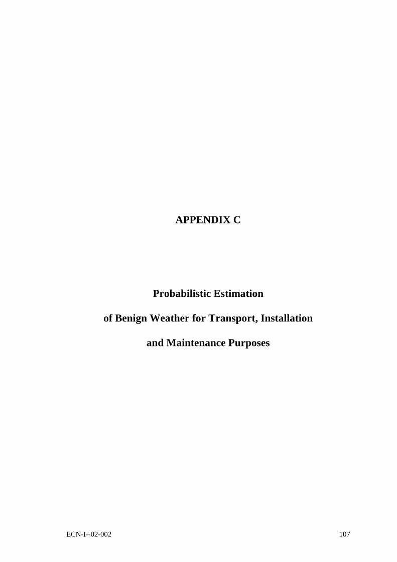
ECN-I--02-002 107
APPENDIX C
Probabilistic Estimation
of Benign Weather for Transport, Installation
and Maintenance Purposes


ECN-I--02-002 109
APPENDIX C. PROBABILISTIC ESTIMATION OF BENIGNWEATHER FOR TRANSPORT, INSTALLATIONAND MAINTENANCE PURPOSES
C.1 Introduction
In order to estimate the benign conditions for transport, installation and maintenance purposes,two probabilistic calculations are needed:1. The probability of non-exceedance of a specific wave height, and2. The probability of a benign weather window, within the previous condition.
Besides, if for maintenance purposes a helicopter is considered, the probability of exceeding aspecific wind speed must be analysed in a similar way as the probability of exceeding a specificwave height.
C.2 Probability of Exceeding a Wave Height
This probability is estimated using a Weibull approximation of a known scatter diagram. Somescatter diagrams of the Exclusive Economic Zone of the Netherlands (Dutch EEZ) have beenderived from [23].
The available data is a compilation of measurements of environmental parameters of ninelocations in the Dutch EEZ, see also Figure 36:.
Name Code Co-ordinates Geographical co-ordinates
Waterdepth
x y NB OL [m]K13a platform K13 10,176 583,334 53º13’04" 3º13’13" 30SchiermonnikoogNoord
SON 206,527 623,483 53º35’44" 6º10’00" 19
Eierlandse Gat ELD 106,514 587,985 53º16’37" 4º39’42" 26IJmuidenmunitiestortplaats
YM6 64,779 507,673 52º33’00" 4º03’30" 21
Noordwijk meetpost MPN 80,443 476,683 52º16’26" 4º17’46" 18Euro platform EUR 9,963 447,601 51º59’55" 3º16’35" 32Lichteiland Goeree LEG 36,779 438,793 51º55’33" 3º40’11" 21Schouwenbank SWB 11,244 419,519 51º44’48" 3º18’24" 20Scheur west SCW 7,797 380,645 51º23’32" 3º02’57" 15

110 ECN-I--02-002
Figure 36: Location of the nine measuring points in the Dutch EEZ.
Voids in the data sets have been filled up by Rijkswaterstaat with measurements andextrapolations from other data sources. Wind and wave data are compiled simultaneously.
From the scatter diagram of each location, a Weibull approximation of the probability densityfunction (PDF) is derived. This procedure is as follows:
The probability of exceeding a wave height at a given location, may be approximated by aWeibull distribution, Equation 55:
]k)c
H([
ref e1)HP(H−
−=≤
k and c are respectively the shape and the scale parameter of the Weibull distribution. The PDFis approximated by a linear equation as follows, Equation 56:
]k)c
H([]k)
c
H([
e)1(e1P−−
=−⇒−= P
kk )c
H()1ln()
c
H()1ln( =−−⇒−=−⇒ PP
)ln(*))1ln(ln(c
HkP =−−⇒
)ln(*)ln(*))1ln(ln( ckHkP −=−−⇒
Thus the Weibull distribution is approximated by the equation Y = A*X + B ifX = ln(H)Y = ln(-ln(1-P))k = AB = -k*ln(c) Å c = exp(-B/k)
An example of fitting the data with a Weibull distribution is shown in Figure 37: Weibullfitting.

ECN-I--02-002 111
Weibull fitting
y = 1.5089x - 0.0081
-4.00000
-3.00000
-2.00000
-1.00000
0.00000
1.00000
2.00000
3.00000
-3.0000 -2.0000 -1.0000 0.0000 1.0000 2.0000
K13 Summer Linear (K13 Summer)
Figure 37: Weibull fitting.
This procedure has been repeated for all nine offshore locations. The results are presented in thetable below:
Co-ordinates Weibull parametersNB OL Summer Whole year
Offshore location Code
deg min sec deg min sec k c k cEierlandse Gat ELD 53 16 37 4 39 42 1.4792 0.9552 1.3969 1.2948IjmuidenMunitiestortplaats
YM6 52 33 0 4 3 30 1.4273 0.8910 1.3585 1.2083
Meetpunt Noordwijk MPN 52 16 26 4 17 46 1.4232 0.7674 1.2840 0.9743K13a platform K13 53 13 4 3 13 13 1.5089 1.0054 1.4825 1.4229Euro platform EUR 51 59 55 3 16 35 1.5892 0.9293 1.5244 1.2232SchiermonnikoogNoord
SON 53 35 44 6 10 0 1.4360 0.4920 1.3369 0.5984
Lichteiland Goeree LEG 51 55 33 3 40 11 1.6047 0.9743 1.3769 1.1209Schouwenbank SWB 51 44 48 3 18 24 1.4587 0.8408 1.4372 1.0381Scheur West SCW 51 23 32 3 2 57 1.4690 0.7072 1.4329 0.8355
Figure 38 shows an example of a Weibull fitting for the wave heights of the K13 platform in thesummer period.
Cummulative probability distribution
0.00000
0.20000
0.40000
0.60000
0.80000
1.00000
1.20000
0.12
50.
625
1.12
51.
625
2.12
52.
625
3.12
53.
625
4.12
54.
625 5
Wave height
K13 Summer
Weibull
Figure 38

112 ECN-I--02-002
Probability of benign weather window
A benign weather window is a window of time where the considered vessel is able to work. Iffor instance a minimum of 3 days is required for a certain activity, every weather window largerthan 3 days is accounted.
This probability is given by Equation 57:
ii
N
ki
effectivePWLPbenignP )(*)()( ∑=
=
P(WL)i is the probability of a particular weather window length. This probability depends on thewave height considered. P(WL) actually means “the probability that a certain weather windowoccurs given a particular wave height”. In the above formula, k represents the weather windownumber that is equal or longer than the minimum weather window required to realise theoperation.
P(effective)i represents the probability of effective time of operation. The probability ofrealising the operation depends on which moment the decision is taken to start with theoperation.To illustrate this, let’s assume that a weather window has a length of 5 hours wherein it isneeded to realise an operation that takes 3 hours time. If the decision of starting the operationtakes place during the 1st or 2nd hour, the activity may be realised. But if the decision of startingthe operation takes place during the 3rd, 4th or 5th hour, it will not possible to realise theoperation because lack of time.The probability of realising an operation of 3 hours within a window length of 5 hours is givenby 1-3/5.
In general terms, the probability of carrying out an activity of length X within a weatherwindow of length WLi is given by Equation 58:
ii WL
XeffectiveP −= 1)(
The probability of a benign weather window, where an operation may take place is then givenby Equation 59:
)1(*)()(ii
i WL
XWLPbenignP −= ∑
Example:WL_ref = 2 [h]
Length Occurrences Probability P(effective) P(benign)i
WL [h] Qi P(WL) Pi P(WL)*Pi1 19 0.2088 0.0000 0.002 25 0.2747 0.0000 0.003 20 0.2198 0.3333 0.074 15 0.1648 0.5000 0.085 12 0.1319 0.6000 0.08
91 1 0.23 = P(benign)

ECN-I--02-002 113
APPENDIX D
Typical Transport and Installation Vessels

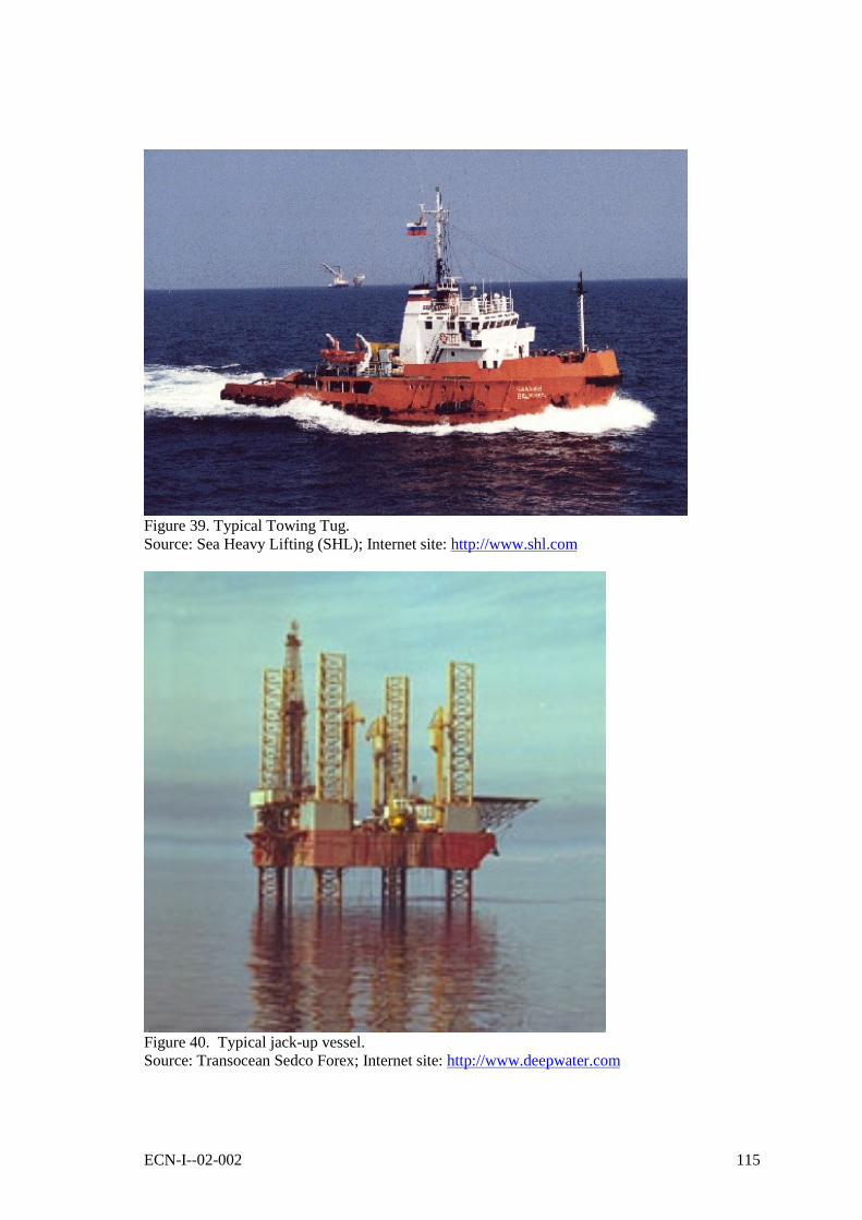
ECN-I--02-002 115
Figure 39. Typical Towing Tug.Source: Sea Heavy Lifting (SHL); Internet site: http://www.shl.com
Figure 40. Typical jack-up vessel.Source: Transocean Sedco Forex; Internet site: http://www.deepwater.com

116 ECN-I--02-002
Figure 41. Derrick barge.Source: Global Industries Ltd.; Internet site: http://www.globalind.com
Figure 42. Typical Construction vessel.Source: Saipem S.p.A.; Internet site: http://www.saipem.it
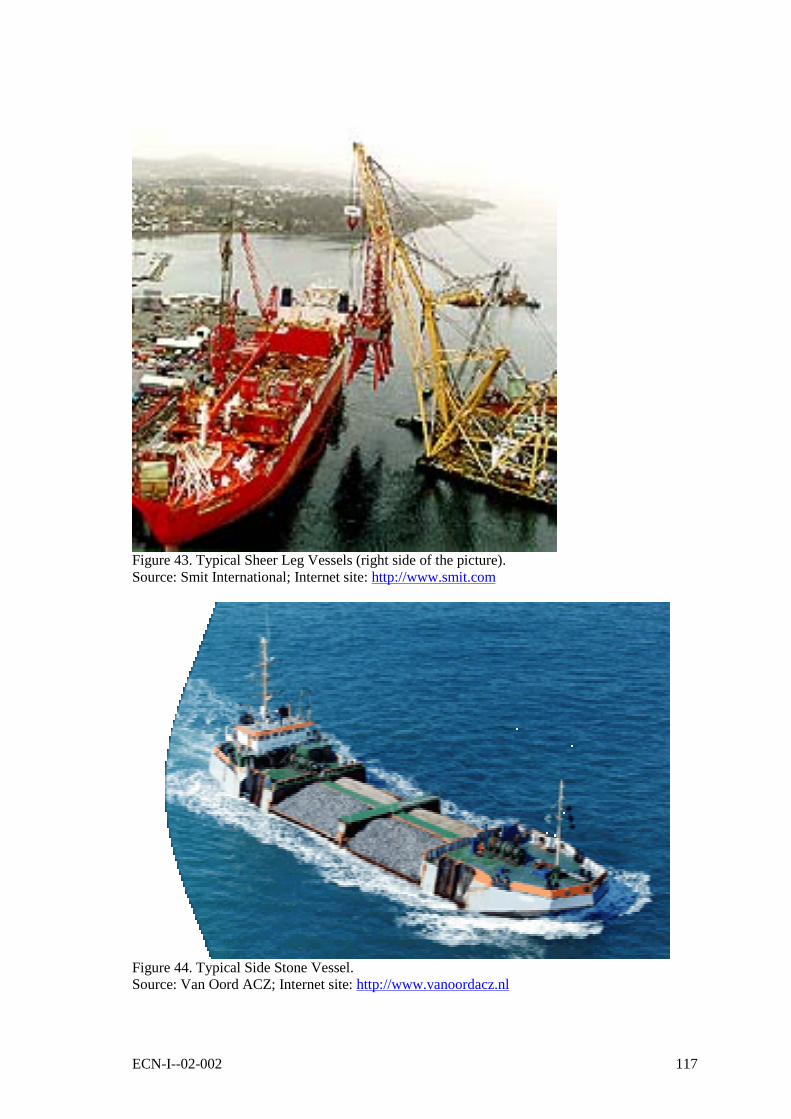
ECN-I--02-002 117
Figure 43. Typical Sheer Leg Vessels (right side of the picture).Source: Smit International; Internet site: http://www.smit.com
Figure 44. Typical Side Stone Vessel.Source: Van Oord ACZ; Internet site: http://www.vanoordacz.nl

118 ECN-I--02-002
Figure 45. Typical Remote Operating Vehicle (ROV).Source: Van der Stoel Cable, Submarine Cable Installation Contractors;
CD-Rom with company profile, version 01-08-2000
Figure 46. Installation of rotor at Middelgrunden wind farm.Wings and hub are raised horizontally until they can be tilted into vertical position. Then theyare elevated to a height of 75 meters before they are mounted onto the nacelle.Source: Middelgrunden Internet site: http://www.middelgrunden.dk

ECN-I--02-002 119
Figure 47. Special Installation barge for the gravity base support structure at Middelgrunden.When the barge is in place by Middelgrunden, several anchors are layed out, they are used tomanouvre the barge so the turbine is in the right spot, it must be within 25 cm of the calculatedposition.Source: Middelgrunden Internet site: http://www.middelgrunden.dk
Figure 48. Typical Cable Trencher Vehicle.Source: Van der Stoel Cable, Submarine Cable Installation Contractors; CD-Rom withcompany profile, version 01-08-2000

120 ECN-I--02-002
11. SPECIAL INSTALLATION BARGES
Figure 49. Turbine Installation Vessel TIV-1.The vessel will have the following characteristics:1. GENERAL- Class: DNV +1A1, Self-elevating Unit, EO DYNAPOS-AUT, Crane- Number of Jackup Legs : 6- Flag State: Isle of Man- Operating Area: Unrestricted- Range 25 Days - Full Crew / Deck Load- Length: 130.50 metres; Breadth: 38.00 metres; Depth: 8.00 metres2. CARGO & ACCOMMODATION CAPACITY- Type / Number: Offshore Wind Turbines / 10- Maximum Payload: 3,000 Te Jacking- MAIN Crane - Max Capacity
- 300 Te @ 25.5 metres- 250 Te @ 29.5 metres- 240 Te @ 30.5 metres- 200 Te @ 35.0 metres- 50 Te @ 80.0 metres
- Auxiliary Crane 50 e @ 35.00 metre radius- Accommodation: 50 Single Berths 2.6 Utilities: Hospital-Recreation3. OPERATING CONDITIONS- Service: Unrestricted (as per DNV Rules)- Jacking Operations: 3.0 metre maximum wave- Jacked Survival 100 Year Storm (Force 12 Beaufort Scale) 50 year wave 14.0 metres- Minimum Operating Depth 10% Cargo: 2.25 metres- Minimum Operating Depth 100% Cargo: 3.25 metres- Max Operating Depth: 35.00 metres (increase possible)4. PERFORMANCE- Transit Speed: 10.5 Knots +- Jacking Capacity: 2500 Te per leg; Holding Capacity: 3500 Te per leg- Jacking Speed: 1m/min- Maximum Draught Loaded: 3.0 metres- Maximum Draught Lightship: 2.4 metresSource: Website of Mayflower Energy Ltd: http://www.mayflower-energy.com.

ECN-I--02-002 121
Figure 50. Very Heavy Lifting Vessel, The Svanen.Artist impression of the Svanen while loading wind turbine components for transport offshore.Courtesy: Ballast Nedam; http://www.ballast-nedam.nl.
Figure 51. Very Heavy Lifting Vessel, The Svanen.Artist impression of the Svanen while installing a tower-nacelle-rotor assembly of a windturbine on its support structure offshore. Courtesy: Ballast Nedam; http://www.ballast-nedam.nl.

122 ECN-I--02-002
Figure 52. Very Heavy Lifting Vessel, The Svanen.The Svanen in action during the transport of a bridge piece. Courtesy: Ballast Nedam;http://www.ballast-nedam.nl.