Embed Size (px)
Citation preview
Offline Simultaneous Localization and Offline Simultaneous Localization and Mapping (SLAM) using Miniature Robots Mapping (SLAM) using Miniature Robots
• Objectives• SLAM approaches• SLAM for ALICE
– EKF for Navigation– Mapping and Network Modeling
• Test results
Philipp Schaer and Adrian WaegliJune 29, 2007
ALICE ALICE --ROBOTROBOT
• Alice As cheap and small as possible– 2 SWATCH motors with wheels and tires (max speed: 40mm/s) – 4 active IR proximity sensors (reflection measurement)– Microcontroller with 8Kwords Flash program memory – Radio communication module
22mm
20m
m
60°4cm
Obj
ectiv
es
1/2
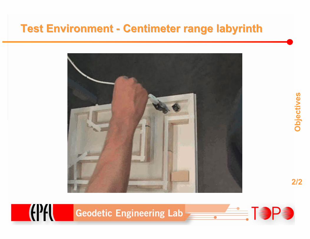
Test Environment Test Environment -- Centimeter range labyrinthCentimeter range labyrinth
Obj
ectiv
es
2/2
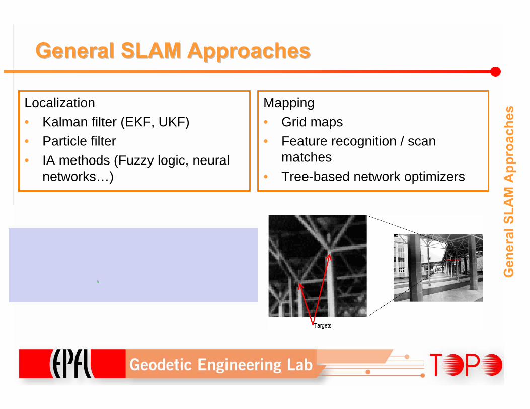
General SLAM ApproachesGeneral SLAM Approaches
Localization• Kalman filter (EKF, UKF)• Particle filter• IA methods (Fuzzy logic, neural
networks…)
Gen
eral
SLA
M A
ppro
ache
sMapping• Grid maps• Feature recognition / scan
matches• Tree-based network optimizers
SLAM for ALICESLAM for ALICE
• EKF for navigation• 3 approaches for mapping:
– Grid mapping– Boundary detection based on range measurements– Network reconstruction
SLA
M fo
r ALI
CE
1/7
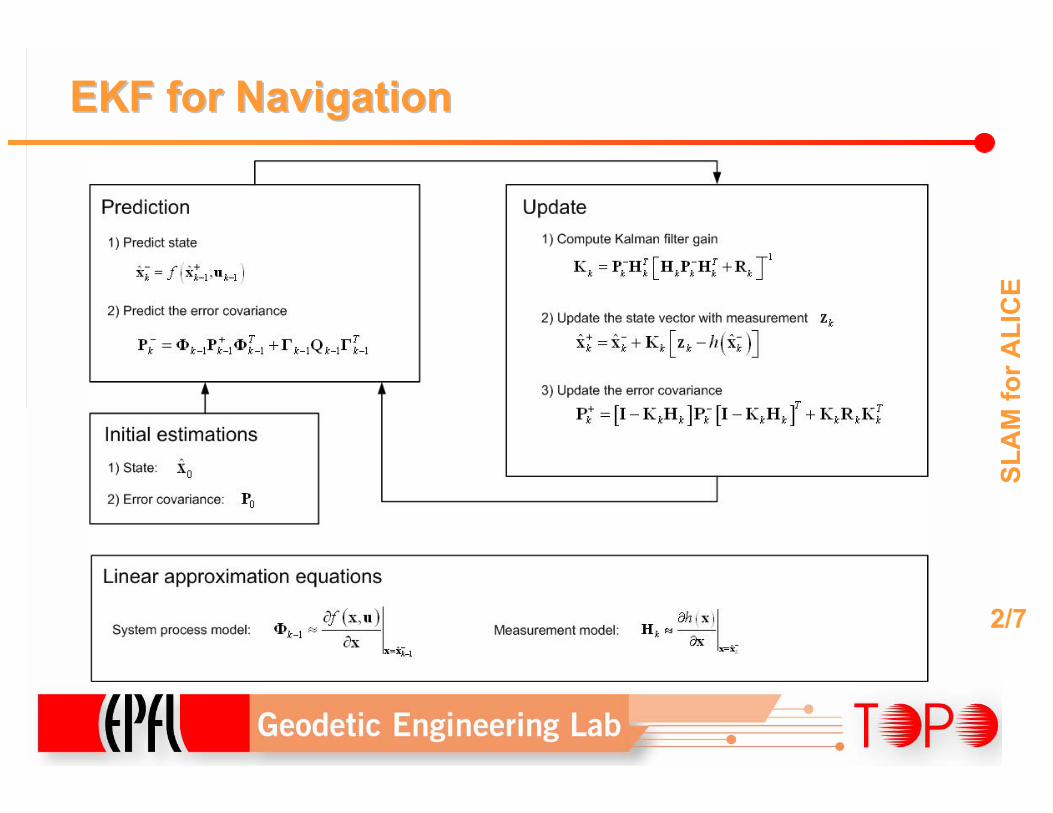
EKF for NavigationEKF for Navigation
SLA
M fo
r ALI
CE
2/7
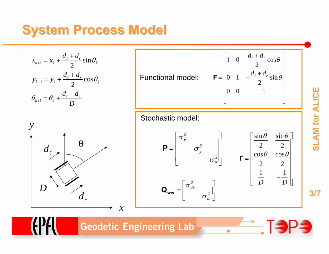
System Process Model System Process Model
1
1
1
sin2
cos2
rk k k
rk k k
rk k
d dx x
d dy y
d dD
θ
θ
θ θ
+
+
+
+= +
+= +
−= +
l
l
l
1 0 cos2
0 1 sin2
0 0 1
r
r
d d
d d
θ
θ
+⎡ ⎤⎢ ⎥⎢ ⎥
+⎢ ⎥= −⎢ ⎥⎢ ⎥⎢ ⎥⎢ ⎥⎣ ⎦
F
l
l
2
2
2
x
y
θ
σσ
σ
⎡ ⎤⎢ ⎥= ⎢ ⎥⎢ ⎥⎣ ⎦
P
2
2d
dr
σσ
⎡ ⎤= ⎢ ⎥⎣ ⎦
wwQ l
sin sin2 2
cos cos2 21 1D D
θ θ
θ θ
⎡ ⎤⎢ ⎥⎢ ⎥⎢ ⎥= ⎢ ⎥⎢ ⎥⎢ ⎥−⎢ ⎥⎣ ⎦
Γ
Functional model:
Stochastic model:
x
y
θdl
rdD
SLA
M fo
r ALI
CE
3/7
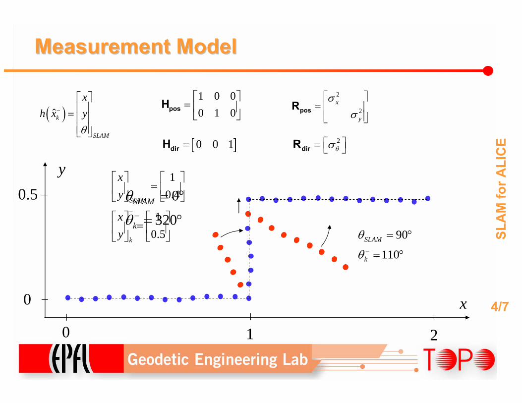
Measurement Model Measurement Model
0
320SLAM
k
θ
θ −
= °
= °
10.4
10.5
SLAM
k
xy
xy
−
⎡ ⎤ ⎡ ⎤=⎢ ⎥ ⎢ ⎥
⎣ ⎦ ⎣ ⎦
⎡ ⎤ ⎡ ⎤=⎢ ⎥ ⎢ ⎥
⎣ ⎦ ⎣ ⎦
1 0 00 1 0⎡ ⎤
= ⎢ ⎥⎣ ⎦
posH
[ ]0 0 1=dirH
( )ˆk
SLAM
xh x y
θ
−
⎡ ⎤⎢ ⎥= ⎢ ⎥⎢ ⎥⎣ ⎦
2
2x
y
σσ
⎡ ⎤= ⎢ ⎥⎢ ⎥⎣ ⎦
posR
2θσ⎡ ⎤= ⎣ ⎦dirR
90
110SLAM
k
θ
θ −
= °
= °
x
y0.5
0
0 1 2
SLA
M fo
r ALI
CE
4/7
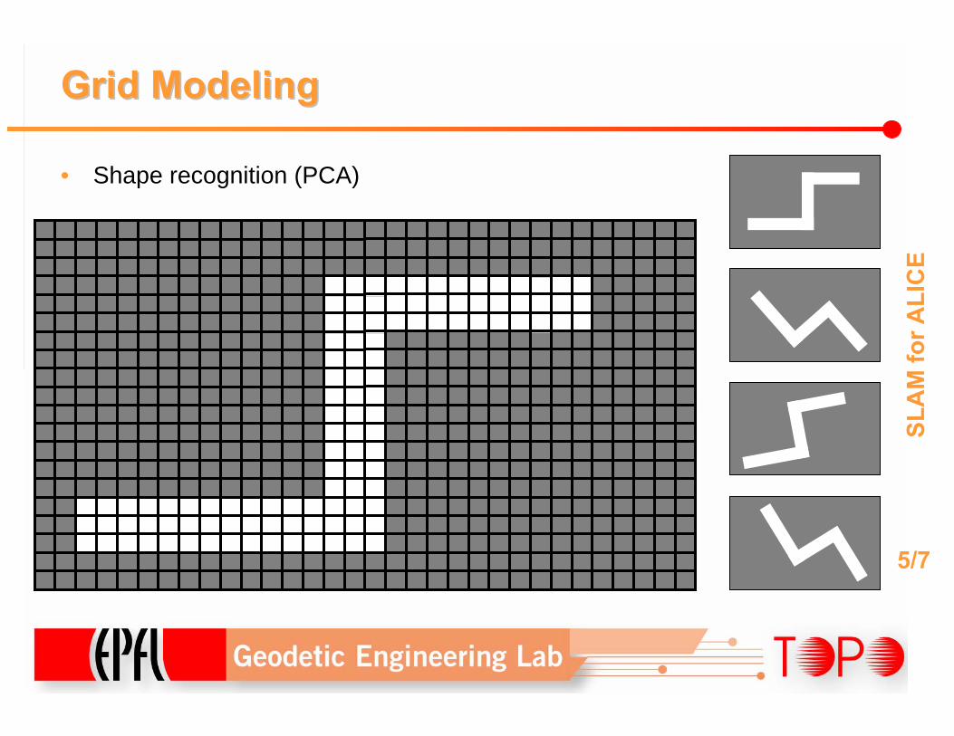
Grid ModelingGrid Modeling
• Shape recognition (PCA)
SLA
M fo
r ALI
CE
5/7
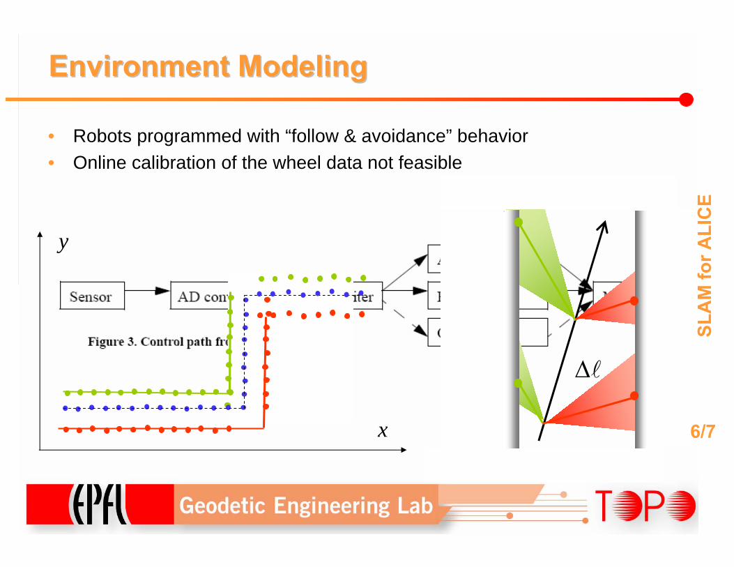
∆l
Environment ModelingEnvironment Modeling
• Robots programmed with “follow & avoidance” behavior• Online calibration of the wheel data not feasible
SLA
M fo
r ALI
CE
6/7x
y
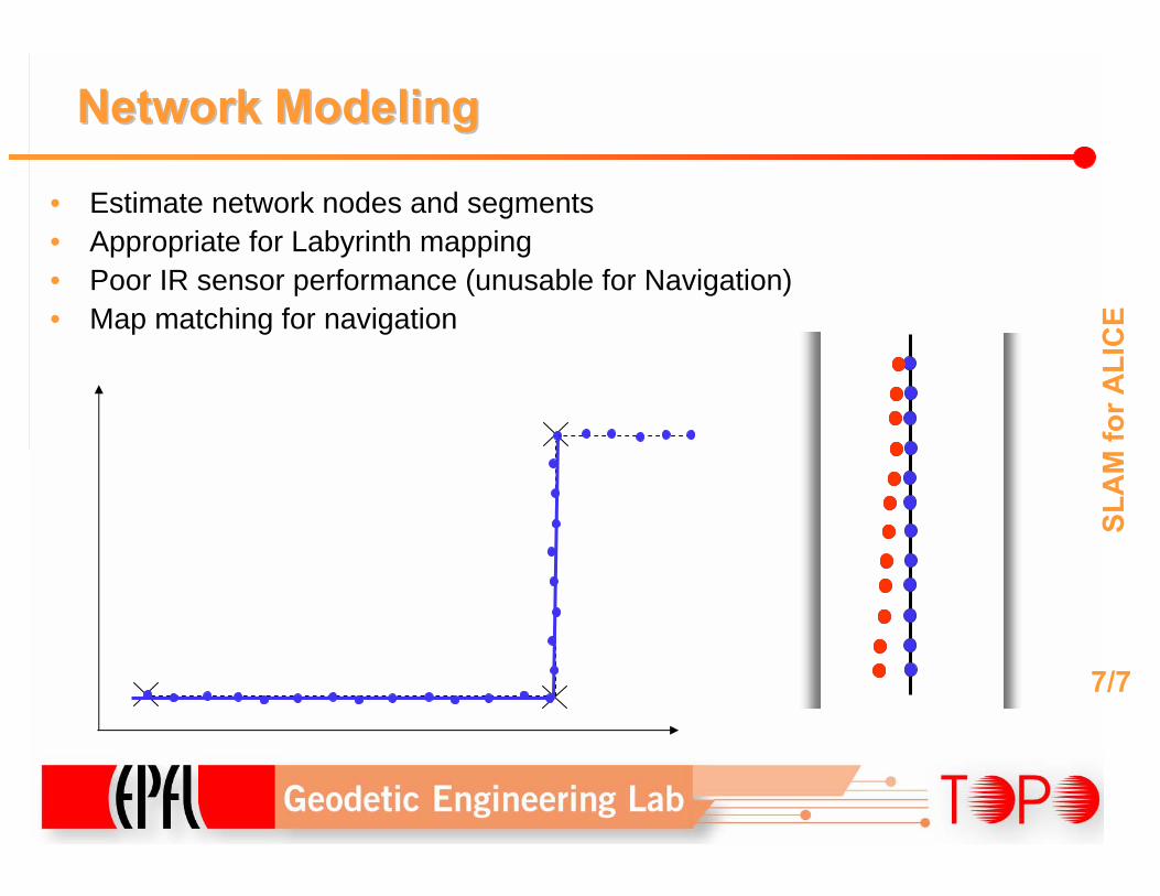
• Estimate network nodes and segments• Appropriate for Labyrinth mapping• Poor IR sensor performance (unusable for Navigation)• Map matching for navigation
Network ModelingNetwork Modeling
SLA
M fo
r ALI
CE
7/7
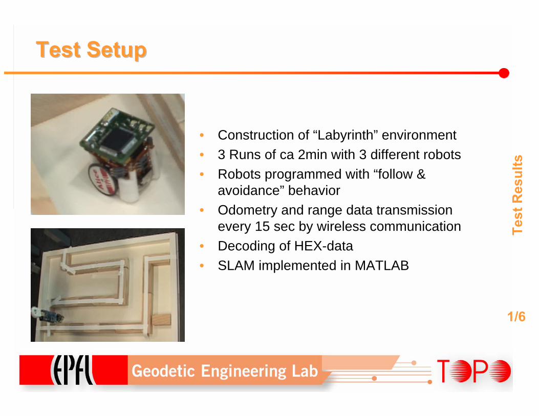
Test SetupTest Setup
Test
Res
ults
• Construction of “Labyrinth” environment • 3 Runs of ca 2min with 3 different robots• Robots programmed with “follow &
avoidance” behavior• Odometry and range data transmission
every 15 sec by wireless communication• Decoding of HEX-data• SLAM implemented in MATLAB
1/6
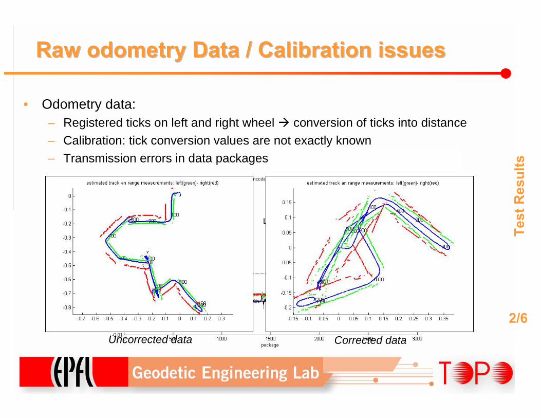
RawRaw odometryodometry Data / Calibration issuesData / Calibration issues
Test
Res
ults
• Odometry data: – Registered ticks on left and right wheel conversion of ticks into distance– Calibration: tick conversion values are not exactly known– Transmission errors in data packages need to “correct” and “cut” data
2/6Left tick = right tick Left tick = 0.98* right tick
Max
. pos
sibl
e sp
eed
(40m
m/s
Length of one data block
Uncorrected data Corrected data
x
y
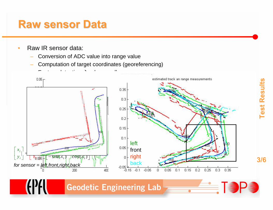
RawRaw sensorsensor DataData
• Raw IR sensor data: – Conversion of ADC value into range value– Computation of target coordinates (georeferencing)– Feature detection edges, walls
Test
Res
ults
3/6
xc(i),yc(i)
αsensor
γ(i)
xt(i),yt(i)
asensor
cos( ) sin( ) sin( )*
sin( ) cos( ) cos( )i i sensor
ii i se
sensoi
orr
i n
i
i s
xa
Xr
Yyλ λ αλ λ α
⎛ ⎞⎡ ⎤ ⎡ ⎤= + +⎜ ⎟⎢ ⎥ ⎢ ⎥⎜ ⎟−⎣ ⎦ ⎣
⎡ ⎤
⎦⎝⎢
⎡ ⎤⎢⎣
⎥⎦ ⎦⎣ ⎠
⎥r
for sensor = left,front,right,back
r(i)
leftfront rightback
GridGrid ModellingModelling ((OccupancyOccupancy GridGrid MapMap))
Test
Res
ults
4/6
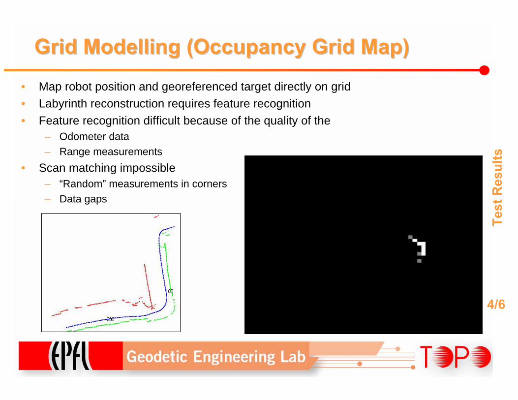
• Map robot position and georeferenced target directly on grid• Labyrinth reconstruction requires feature recognition• Feature recognition difficult because of the quality of the
– Odometer data– Range measurements
• Scan matching impossible– “Random” measurements in corners– Data gaps
BoundaryBoundary DetectionDetection
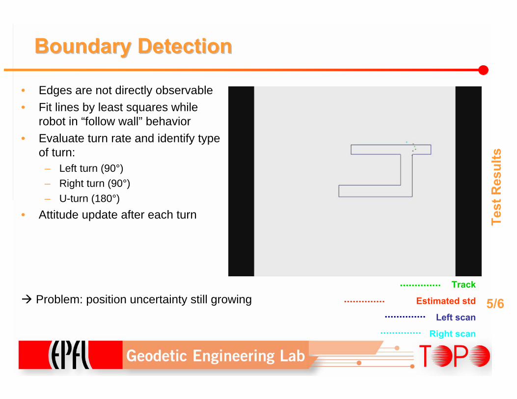
• Edges are not directly observable• Fit lines by least squares while
robot in “follow wall” behavior• Evaluate turn rate and identify type
of turn:– Left turn (90°)– Right turn (90°)– U-turn (180°)
• Attitude update after each turn Test
Res
ults
5/6Problem: position uncertainty still growingTrack
Estimated std
Left scan
Right scan
Network Network ModellingModelling ApproachApproach
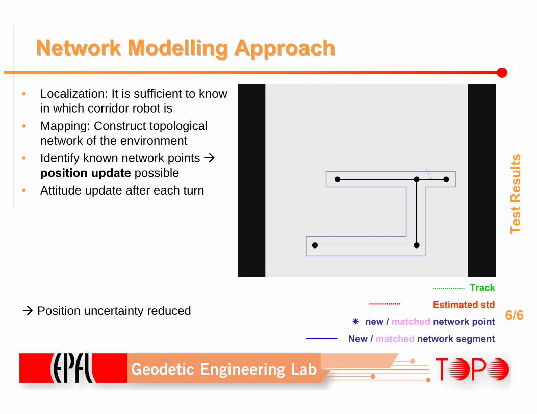
• Localization: It is sufficient to know in which corridor robot is
• Mapping: Construct topological network of the environment
• Identify known network points position update possible
• Attitude update after each turn
Test
Res
ults
6/6Position uncertainty reduced
Track
Estimated std
new / matched network point
New / matched network segment
ConclusionConclusion
• Grid estimation approach not applicable:– Feature recognition and scan matching almost impossible
• Boundary detection possible, but cumbersome:– Implicit boundary detection by “follow wall” behavior (robots runs on straight
line)– Poor quality of georeferencing in turns – Difficult to implement position updates
• Network estimation seems to be the most appropriate method for labyrinth mapping for the given sensors:– More robust in turns– Easier topology recognition– Loop closure at every matched network point– Map matching along line segments
Con
clus
ion
1/2
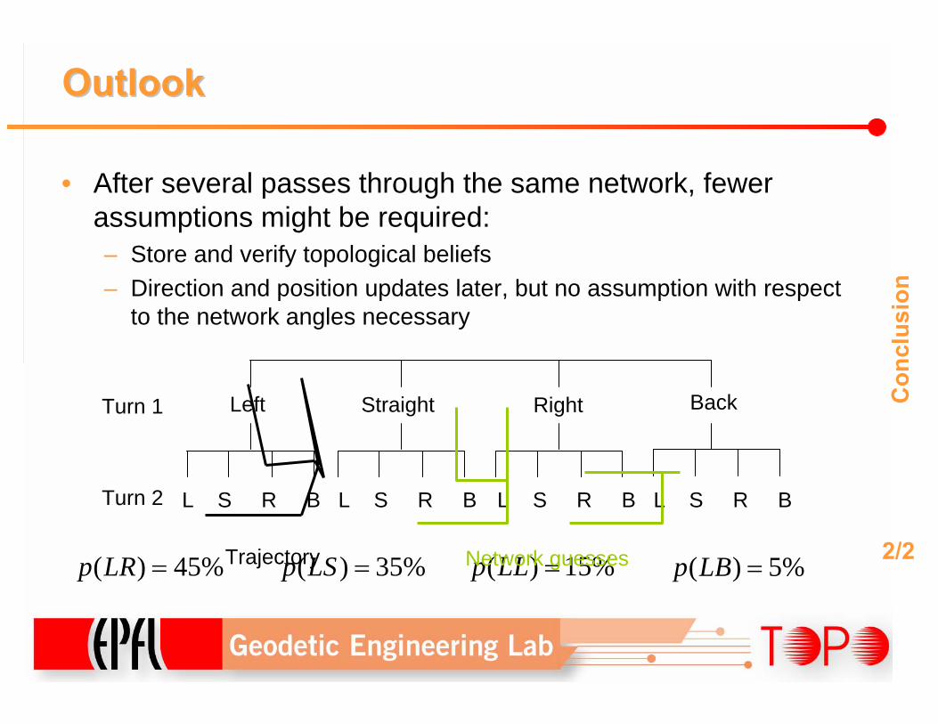
OutlookOutlook
• After several passes through the same network, fewer assumptions might be required:– Store and verify topological beliefs– Direction and position updates later, but no assumption with respect
to the network angles necessary
Con
clus
ion
2/2( ) 45%p LR =
Left Straight Right BackTurn 1
Turn 2 L S R B L S R B L S R B L S R B
( ) 15%p LL =( ) 35%p LS = ( ) 5%p LB =Trajectory Network guesses