Embed Size (px)
Citation preview

Ofcom
Digital Dividend Study
International
Interference Assessment
Mason Communications Ltd
5 Exchange Quay
Manchester M5 3EF
United Kingdom
Tel: +44 (0)161 877 7808
Fax: +44 (0)161 877 7810
e-mail: [email protected] www.mason.biz
August 2007

Ofcom
Digital Dividend Study
International Interference Assessment
Copyright © 2007
The information contained herein is the property of Mason Communications Ltd and is
provided on condition that it will not be reproduced, copied, lent or disclosed, directly or
indirectly, nor used for any purpose other than that for which it was specifically furnished.
C Ofcom Comments Included
SIGNATURE
NAME Adrian Dain Janette Dobson Alex Sowerby Janette Dobson 21 August 2007
B Ofcom Comments Included
SIGNATURE
NAME Lucky Zhang /
Adrian Dain Janette Dobson Alex Sowerby Janette Dobson 25 July 2007
A Channels 38, 60, 61 and 62 added
SIGNATURE
NAME Lucky Zhang / Adrian Dain
Janette Dobson Alex Sowerby Janette Dobson 6 June 2007
PREPARED BY REVIEWED BY CHECKED BY APPROVED BY DATE
REV DOCUMENT REFERENCE NUMBER
9XHA001C
Page 1 of 11

9XHA001C | 1
CONTENTS
1. Introduction.................................................................................................................... 2
1.1 Scope of D1.1 (b) .................................................................................................. 2
1.2 Released Spectrum ................................................................................................ 4
2. Methodology.................................................................................................................. 4
2.1 Planning tool configuration.................................................................................... 4
2.2 Detail of Propagation Model Settings..................................................................... 5
2.3 Process .................................................................................................................. 6
3. Coordination Requirement Modelling Examples ............................................................ 8
3.1 Interference from UK assignment G–10104/37 to France....................................... 8
3.2 Interference from Holland to UK example ........................................................... 10
APPENDICES
Appendix A UK Exported Interference Plots
Appendix B Holland Exported Interference Plots
Appendix C Belgium Exported Interference Plots
Appendix D France Exported Interference Plots
Appendix E Ireland Exported Interference Plots
Appendix F Belgium, Ireland, France and Holland Exported Interference Plots
Appendix G UK Service Areas and BEL, IRL, F, HOL Allotment areas
9XHA001C | 2
1. Introduction
This report forms deliverable D1.1 (b) of ‘Digital Dividend – Study on
Compatibility/Technical Usage Conditions’.
1.1 Released Spectrum
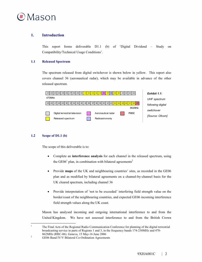
The spectrum released from digital switchover is shown below in yellow. This report also
covers channel 36 (aeronautical radar), which may be available in advance of the other
released spectrum.
21 22 23 24 25 26 27 28 29 30 31 32 33 34 35 36 37 38 39 40 41 42 43 44
470MHz
45 46 47 48 49 50 51 52 53 54 55 56 57 58 59 60 61 62 63 64 65 66 67 68 69
862MHz
Digital terrestrial television Aeronautical radar PMSE
Released spectrum Radioastronomy
Exhibit 1.1:
UHF spectrum
following digital
switchover
[Source: Ofcom]
1.2 Scope of D1.1 (b)
The scope of this deliverable is to:
• Complete an interference analysis for each channel in the released spectrum, using
the GE061 plan, in combination with bilateral agreements2
• Provide maps of the UK and neighbouring countries’ sites, as recorded in the GE06
plan and as modified by bilateral agreements on a channel-by-channel basis for the
UK cleared spectrum, including channel 36
• Provide interpretation of ‘not to be exceeded’ interfering field strength value on the
border/coast of the neighbouring countries, and expected GE06 incoming interference
field strength values along the UK coast.
Mason has analysed incoming and outgoing international interference to and from the
United Kingdom. We have not assessed interference to and from the British Crown
1 The Final Acts of the Regional Radio Communication Conference for planning of the digital terrestrial
broadcasting service in parts of Regions 1 and 3, in the frequency bands 174-230MHz and 470-
862MHz (RRC-06). Geneva, 15 May-16 June 2006 2 GE06 Band IV/V Bilateral Co-Ordination Agreements

9XHA001C | 3
Dependencies (Channel Islands and the Isle of Man) or the British Overseas Territories that
are party to the GE06 plan (e.g. Gibraltar).3
In addition to the released spectrum, this issue of this report also includes information on
channels . 60, . 61 . and . 62. . .
1.3 The Coordination Process
The GE06 plan includes both channel assignments and channel allotments. Channel
assignments are specific transmitter locations with a stated transition channel transmit power
and antenna height. The assignments are usually entered into the plan as Omni directional
antennas (as in the case of the UK). However, in practice many digital-terrestrial television
(DTT) main sites will employ carefully tailored antenna patterns to meet the target coverage
area. So, the level of international interference may be less than that suggested within the
GE06 plan.
Where administrations were not ready to apply for transmitter assignments at the Regional
Radiocommunication Conference (RRC06) – perhaps because transmitter locations were not
known – they were granted channel allotments. An allotment is a ‘place holder’ that reserves
a channel for a specific geographical area without necessarily detailing all transmitter
locations.
Before a channel allotment can be used for broadcast it needs to be converted to one or more
transmitter assignments. These assignments will be entered into the GE06 plan and, if
necessary, amendments to the bilateral coordination agreements will be made to mitigate
interference prior to the assignment being entered into the frequency plan.
At the time of writing, several channel allocations in France and the Netherlands are still at
the allotment stage. Thus the level of interference once these are converted to assignments
may be different from the interference shown in the appendices of this report.
3 Ofcom represents the UK in the ITU. Ofcom also represents the British Overseas Territories, the
Channel Islands, and the Isle of Man under informal arrangements agreed between the respective
governments.

9XHA001C | 4
2. Methodology
2.1 Planning Tool Configuration
Radio planning tool ICS Telecom 8.2.3 was used to predict imported and exported
interference with the following parameters:
• Digital terrain model (DTM): 500m horizontal, 1m vertical resolution (see Figure 2.1)
• Propagation model: ITU-R P.1546-2
• Transmitter location, height and ERP: as per GE06 assignments or allotments
adjusted to comply with international bilateral agreements between the UK and the
following neighbouring countries:
o Belgium
o France
o The Netherlands
o The Republic of Ireland
• Receiver antenna height: 10m above ground level
• Calculation distance limit: 1000km
• Field strength displayed using the ‘Power Sum Coverage Display’.

9XHA001C | 5
Figure 2.1: Digital Terrain Model used for Interference Analysis
2.2 Detail of Propagation Model Settings
The propagation parameters used for coverage predictions are:
• Variability – 50% of locations, 1% of time
• Sea path – cold
• Terrain clearance angle selected, to make best use of the DTM
• Emission – digital broadcast selected.

9XHA001C | 6
Figure 2.2: Propagation Model ITU-R P.1546-2 Specific Settings
2.3 Process
Initially coverage was predicted using the assignment transmitter parameters detailed in the
GE06 agreement.
Where no assignments were included within the GE06 agreement, but instead allotments are
recorded, Mason has done the following, in order of preference:
• Where reference assignments have been included in the bilateral agreements for the
purpose of coordination, these have been used
• Where actual candidate transmitter sites are known these have been used, as in the
case of the Netherlands
• Failing this, Mason has modelled transmitter characteristics within the allotment in
accordance with the GE06 reference network stated within the GE06 allotment entry.
Each coordination requirement in each bilateral agreement was then analysed and restrictions
were applied to transmitters as per the agreement. The coordination requirements are worded
in one of the following ways:
• A revised transmit power between two specific Tx azimuth bearings (e.g. 43dbW,
80-90deg)
• A power reduction between two specific Tx azimuth bearings (e.g. –7dB, 80-90deg)
• A requirement to reduce interference to a specific level at the coastline (e.g.
29dBµV/m on the coast of France)

9XHA001C | 7
• A requirement to reduce interference to a specific level at the boundary of an
allotment (e.g. 45dBµV/m at allotment boundary HOL0502-64)
• A requirement to reduce interference to a specific level at the boundary of a UK
service area.
In each case the change was achieved by altering the antenna pattern. In order to take
measurements at the boundaries of UK service areas and continental allotment areas it was
necessary to construct a MapInfo Interchange File (.MIF) for each allotment and each service
area. These are shown in Appendix G.

9XHA001C | 8
3. Coordination Requirement Modelling Examples
3.1 Interference from UK assignment G–10104/37 to France
This section details an example of how the UK assignment G–10104/37 (Royal Tunbridge
Wells channel 37) was adjusted to meet the stated coordination requirement in the bilateral
agreement between France and the UK. The same process has been followed throughout the
analysis.
The coordination requirement in this case was stated as ‘Agreed subject to 29dBµV/m co-
polar and 45dBuV/M cross-polar on the French coast’. In cases such as this where
interference limits are quoted as both cross-polar and co-polar we have modelled the most
limiting case, that of co-polar interference. Thus operators who can comply with the
polarization stated in the GE06 plan, which does vary from site to site, will be permitted to
generate more interference than indicated in this analysis. The location of UK assignment G–
10104/37 is shown below in Figure 3.1.
Figure 3.1: UK Assignment G–10104/37
The GE06 plan details for this site state an ERP 36dBW (4kW) and a mast height of 50m. An
interference prediction using these parameters is shown below, in Figure 3.2.

9XHA001C | 9
Figure 3.2: UK Assignment G–10104/37 – Interference Plot
From this prediction we note that the 29dBµV/m interfering field strength stated in the
bilateral agreement for the French coast has been exceeded over a considerable area. To meet
the coordination requirement the UK transmitter power was reduced by 7dB from 90 to 190
degrees and 2dB from 195 to 225 degrees, as shown in Figure 3.3.
Figure 3.3: UK assignment G–10104/37 – Transmitter Adjustments
The revised interference prediction is shown in Figure 3.4.
9XHA001C | 10
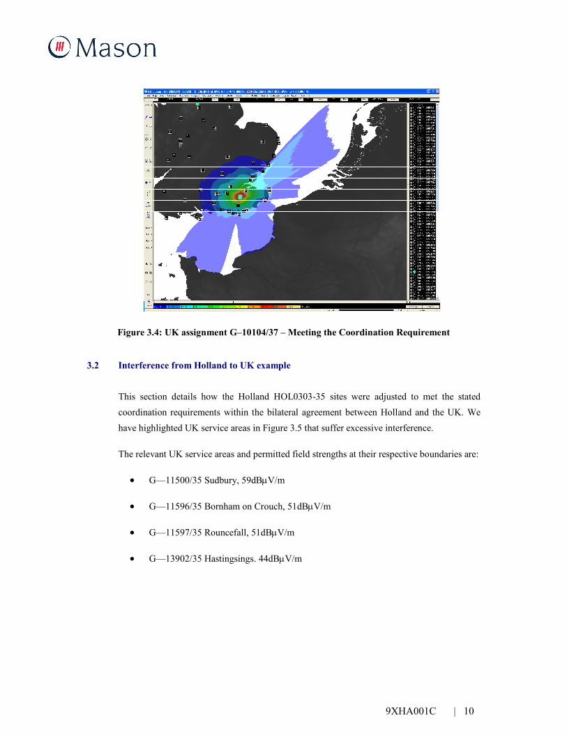
Figure 3.4: UK assignment G–10104/37 – Meeting the Coordination Requirement
3.2 Interference from Holland to UK example
This section details how the Holland HOL0303-35 sites were adjusted to met the stated
coordination requirements within the bilateral agreement between Holland and the UK. We
have highlighted UK service areas in Figure 3.5 that suffer excessive interference.
The relevant UK service areas and permitted field strengths at their respective boundaries are:
• G—11500/35 Sudbury, 59dBµV/m
• G—11596/35 Bornham on Crouch, 51dBµV/m
• G—11597/35 Rouncefall, 51dBµV/m
• G—13902/35 Hastingsings. 44dBµV/m

9XHA001C | 11
Figure 3.5: Holland HOL0303-35 – Interference Plot
To meet the coordination requirement the transmitter power was reduced by 9dB from 230 to
240 degrees, and by 12dB from 245 to 260 degrees. The revised interference prediction is
shown in Figure 3.6.
Figure 3.6: Holland HOL0303-35 – Meeting the Coordination Requirement
Appendix A 9XHA001C | 1
Appendix A
UK Exported Interference Plots

Appendix A 9XHA001C | 1
's-Gravenhage's-Gravenhage's-Gravenhage's-Gravenhage's-Gravenhage's-Gravenhage's-Gravenhage's-Gravenhage's-Gravenhage
ANDORRA LA VELLAANDORRA LA VELLAANDORRA LA VELLAANDORRA LA VELLAANDORRA LA VELLAANDORRA LA VELLAANDORRA LA VELLAANDORRA LA VELLAANDORRA LA VELLA
AntwerpenAntwerpenAntwerpenAntwerpenAntwerpenAntwerpenAntwerpenAntwerpenAntwerpen
BelfastBelfastBelfastBelfastBelfastBelfastBelfastBelfastBelfast
BERNBERNBERNBERNBERNBERNBERNBERNBERN
BirminghamBirminghamBirminghamBirminghamBirminghamBirminghamBirminghamBirminghamBirmingham
BordeauxBordeauxBordeauxBordeauxBordeauxBordeauxBordeauxBordeauxBordeaux
BremenBremenBremenBremenBremenBremenBremenBremenBremen
BRUXELLESBRUXELLESBRUXELLESBRUXELLESBRUXELLESBRUXELLESBRUXELLESBRUXELLESBRUXELLES
DortmundDortmundDortmundDortmundDortmundDortmundDortmundDortmundDortmund
DUBLINDUBLINDUBLINDUBLINDUBLINDUBLINDUBLINDUBLINDUBLIN
Frankfurt am MainFrankfurt am MainFrankfurt am MainFrankfurt am MainFrankfurt am MainFrankfurt am MainFrankfurt am MainFrankfurt am MainFrankfurt am Main
HamburgHamburgHamburgHamburgHamburgHamburgHamburgHamburgHamburg
HannoverHannoverHannoverHannoverHannoverHannoverHannoverHannoverHannover
K_BENHAVNK_BENHAVNK_BENHAVNK_BENHAVNK_BENHAVNK_BENHAVNK_BENHAVNK_BENHAVNK_BENHAVN
K_lnK_lnK_lnK_lnK_lnK_lnK_lnK_lnK_ln
LeedsLeedsLeedsLeedsLeedsLeedsLeedsLeedsLeeds
LONDONLONDONLONDONLONDONLONDONLONDONLONDONLONDONLONDON
LUXEMBOURGLUXEMBOURGLUXEMBOURGLUXEMBOURGLUXEMBOURGLUXEMBOURGLUXEMBOURGLUXEMBOURGLUXEMBOURG
LyonLyonLyonLyonLyonLyonLyonLyonLyon
MarseilleMarseilleMarseilleMarseilleMarseilleMarseilleMarseilleMarseilleMarseille
MilanoMilanoMilanoMilanoMilanoMilanoMilanoMilanoMilano
MONACOMONACOMONACOMONACOMONACOMONACOMONACOMONACOMONACO
M_nchenM_nchenM_nchenM_nchenM_nchenM_nchen
N_rnbergN_rnbergN_rnbergN_rnbergN_rnbergN_rnbergN_rnbergN_rnbergN_rnberg
OSLOOSLOOSLOOSLOOSLOOSLOOSLOOSLOOSLO
PARISPARISPARISPARISPARISPARISPARISPARISPARIS
REYKJAVIKREYKJAVIKREYKJAVIKREYKJAVIKREYKJAVIKREYKJAVIKREYKJAVIKREYKJAVIKREYKJAVIK
SheffieldSheffieldSheffieldSheffieldSheffieldSheffieldSheffieldSheffieldSheffield
StrasbourgStrasbourgStrasbourgStrasbourgStrasbourgStrasbourgStrasbourgStrasbourgStrasbourg
TorinoTorinoTorinoTorinoTorinoTorinoTorinoTorinoTorino
T_RSHAVNT_RSHAVNT_RSHAVNT_RSHAVNT_RSHAVNT_RSHAVNT_RSHAVNT_RSHAVNT_RSHAVN
VADUZVADUZVADUZVADUZVADUZVADUZVADUZVADUZVADUZ
Channel 31
Field Strength
dBuV/m
29
35
40
45
50
55
60
65
70
75
80
Figure A.1: Channel 31 Coordinated UK Exported Interference