Embed Size (px)
Citation preview
rDesign Of an
A normal by-product of scientific investigation is the continual refinement of the measuring instruments involved. The Navy's navigational satellite system under development
at AP L is a f airly important case in point. The accuracy of a pos,£tion location is highly dependent on the frequency
stabil1'ty that the oscillator in the satellite exhibits .
ULTRASTABLE OSCILLATOR J. B. Oakes, W. J. Billerbeck, K. F. Read
for Satellites
The accuracy of the Navy navigational satellite system is greatly dependent on the stability
and predictability of the quartz crystal oscillator that drives the satellite transmitters. The oscillator, as it had evolved by the time of the successful4B satellite launch in November of last year, is the subject of this article.
Five elements are responsible for frequency drift in crystal oscillators of the type used. These are: (1) temperature of the frequency-controlling elements; (2) power supply voltage; (3) crystal drive power; (4) load impedance; and (5) crystal aging. Every oscillator in the navigational satellite program has been designed to minimize frequency variations arising from these causes.
Early satellites employed a quartz crystal oscillator of the Colpitts type, enclosed in a multiple Dewar flask for thermal isolation.! The crystal itself was in a cylindrical slug of Monel metal at the center of the flask. This slug was supported on low-conductivity plastic spiders inside a larger Monel cylinder. The oscillator circuitry was mounted on a printed circuit board located at one end of this intermediate container, and foampotted to add mechanical rigidity. The resulting assembly was supported on plastic spiders in an outer Monel cylinder. Provision was made for flask evacuation in the vacuum of outer space; the structure thus possessed a reasonably long thermal time constant to reduce orbit-to-orbit temperature variations. Voltage regulation in the power supply was employed. In addition, a silicon diode limiter was used in the oscillator tank circuit to stabilize the crystal drive level. Load effects were reduced by employing a two-stage feedbackstabilized isolation amplifier between the oscillator
I J. W. Hamblen and J. B. Oakes, "Instrumentation and Telemetry of TRANSIT Navigation Satellites", Electronic8, 34, Aug. 11, 1961, 148-153.
10
transistor and the output point. As the APL space program progressed, it be
came apparent that additional improvement was desirable in the relatively long-term stability of the oscillator. By making the Dewar flask thermal time constant several days, the extraction of geodetic information from doppler data was facilitated. Further, the 8-lb Monel flask became an unacceptable fraction of the allowable payload weight. A lightweight flask having a thermal time constant greater than that of the original Monel flask was designed. The outstanding feature of this new flask was that the intermediate container of the lightweight unit was so designed that its temperature could be controlled. Appropriate choice of thermal time constants was made so that the presence of a temperature-controlling element would not degrade the short-term stability of the oscillator. On the other hand, the long-term stability with active temperature control now became a function of the stability of the temperature-controlling element.
Both single thermostatic and single proportional ovens have been investigated as part of our search for improved long-term oscillator stability. The result was selection of the single thermostatic oven for use in the Model 4B satellite.
Therlllal Design of a Satellite-Borne Crystal Oven
The goals established for development of the improved crystal oven were as follows: Improved short-term thermal stability-The need was for minimization of the crystal frequency drift, and therefore minimization of crystal temperature changes, during the time of signal reception by a ground or shipboard station. Temperature variation must be less than O.005°F over any I5-min period.
APL T echnical Digest
Improved long-term thermal stability-Smaller longterm temperature changes due to variations of satellite attitude and percent sunlight exposure were necessary for minimizing long-term crystal frequency changes. This simplifies geodetic calculations and allows more rapid signal acquisition at tracking stations. The desired maximum longterm (seasonal) temperature variation is about 0.20 F. Reduced weight-Reduction in total weight of the 4B satellite was essential. Thermal isolation-It is important that the crystal frequency, and therefore its temperature, be independent of heat dissipation levels in the various satellite packages. It is also important that the crystal temperature be independent of variations in voltage supplied to the crystal oven.
Design Development The achievement of a design to meet the goals
outlined above has required several separate investigations. First, it was planned that the crystal and the oscillator circuit be surrounded by a thermally massive metal slug and that structural weight in the outer portion of the oven be minimized. Second, the crystal slug was to be enclosed in a layer of the best available vacuum insulation. Third, it was considered essential from both the thermal and the electronic points of view that the electrical power dissipated by the elements in the oscillator circuit be as nearly constant as possible; this could be attained by precision input voltage regulation.
The foremost consideration in selecting the insulation is the requirement for the lowest possible thermal conductivity per unit weight. Second, the material must maintain its physical integrity while supporting the crystal slug during boost phase vibration and acceleration. It must also be a material that can be evacuated rapidly without damage during boost into orbit.
I t has been shown in numerous environmental tests that multi-layer reflective-type insulation2 is adaptable to the satellite oscillator package and will satisfy the thermal, structural, vibration, and rapid evacuation requirements discussed above. Two arrangements of reflective shielding have been used on the oscillator packages fabricated by APL. These include alternating layers of aluminized Mylar and fiber glass paper, and layers of aluminum foil and fiber glass paper.
For thermal capacitance surrounding the quartz crystal and its oscillator circuit, it might appear
2 M. P . Hnilicka, "Engineering Aspects of Heat Transfer in Multilayer Reflective Insulation and Performance of NRC Insulation", 1959 Cryogenic Engineering Conference, Berkeley, Calif.
September-October 1962
at first that one should simply select the material having the largest thermal capacity per unit weight, i.e., the largest value of specific heat; from data on metals, ceramics, and plastics, this would clearly indicate the selection of a nylon slug. However, comparative design studies have shown that there is a "growth factor" associated with the size of the crystal slug; if a specific product of slug thermal capacity and insulation thermal resistance is desired, decreasing slug density results in rapid and nonlinear increases in the total size and weight of the crystal oven. Therefore, the thermal design criterion for selection of this slug material in the satellite oscillator packages of recent design has been maximum thermal capacity per unit volume, rather than per unit weight. This led to the choice of Monel.
Thermal Analysis of the System
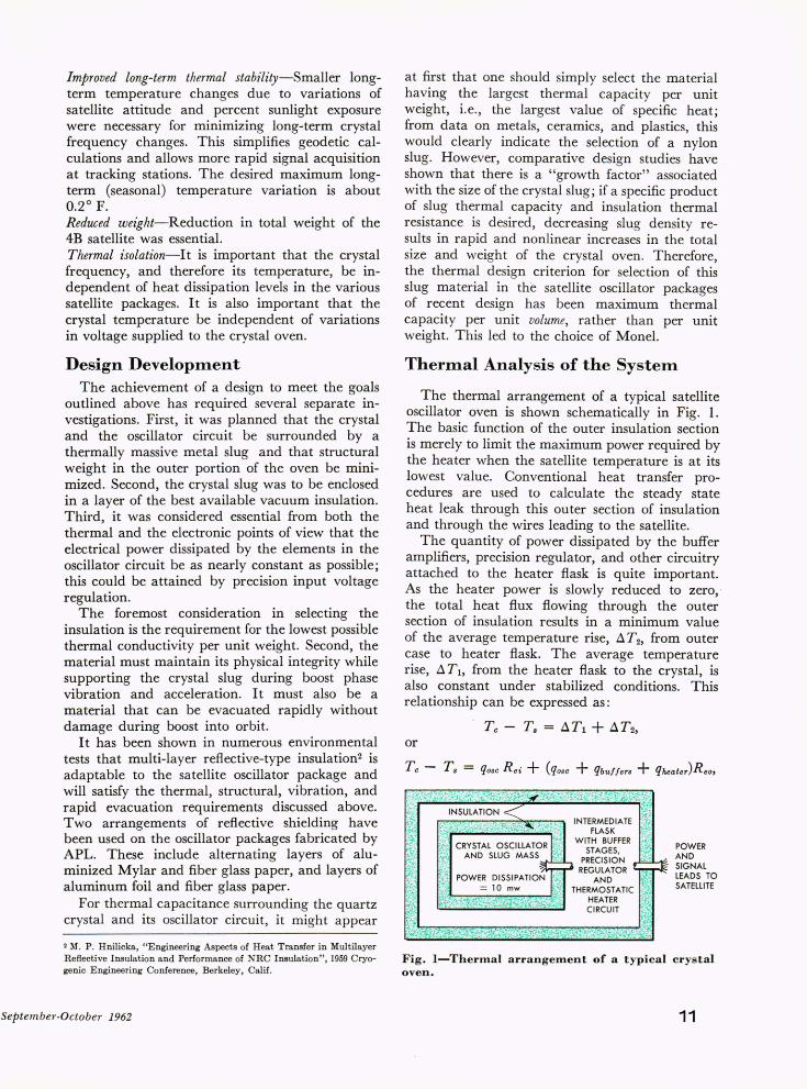
The thermal arrangement of a typical satellite oscillator oven is shown schematically in Fig. 1. The basic function of the outer insulation section is merely to limit the maximum power required by the heater when the satellite temperature is at its lowest value. Conventional heat transfer procedures are used to calculate the steady state heat leak through this outer section of insulation and through the wires leading to the satellite.
The quantity of power dissipated by the buffer amplifiers, precision regulator, and other circuitry attached to the heater flask is quite important. As the heater power is slowly reduced to zero,the total heat flux flowing through the outer section of insulation results in a minimum value of the average temperature rise, AT2, from outer case to heater flask. The average temperature rise, AT!, from the heater flask to the crystal, is also constant under stabilized conditions. This relationship can be expressed as:
Tc - Ts = AT! + AT2,
or
POWER AND SIGNAL LEADS TO SATelLITE
Fig. I-Thermal arrangement of a typical crystal oven.
11
HIGH SATELLITE STRUCTURE TEMPERATURE
LOW SATELLITE STRUCTURE TEMPERATURE
~XIMUM I ---- nn ____ 1 __ 1 __ 1_
THERMOSTAT " MAKE" TEMP.
THERMOSTAT " BREAK" TEMP.
TIME TIME
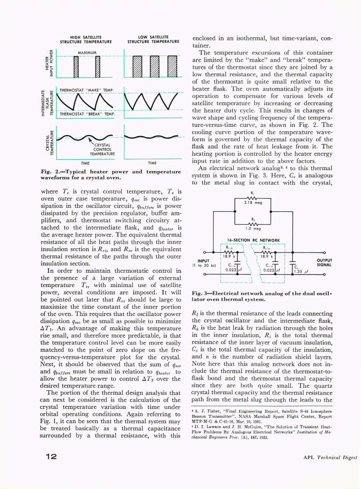
Fig. 2.-Typical heater power and temperature waveforms for a crystal oven.
where Tc is crystal control temperature, T s is oven outer case temperature, q 08C is power dissipation in the oscillator circuit, qbu ffers is power dissipated by the precision regulator, buffer amplifiers, and thermostat switching circuitry attached to the intermediate flask, and q heater is the average heater power. The equivalent thermal resistance of all the heat paths through the inner insulation section is R ei , and R eo is the equivalent thermal resistance of the paths through the outer insulation section.
In order to maintain thermostatic control in the presence of a large variation of external temperature Ts, with minimal use of satellite power, several conditions are imposed. It will be pointed out later that R ei should be large to maximize the time constant of the inner portion of the oven. This requires that the oscillator power dissipation q08C be as small as possible to minimize .6 T 1. An advantage of making this temperature rise small, and therefore more predictable, is that the temperature control level can be more easily matched to the point of zero slope on the frequency-versus-temperature plot for the crystal. Next, it should be observed that the sum of q osc
and qbu ffers must be small in relation to q heater to allow the heater power to control .6 T2 over the desired temperature range.
The portion of the thermal design analysis that can next be considered is the calculation of the crystal temperature variation with time under orbital operating conditions. Again referring to Fig. 1, it can be seen that the thermal system may be treated basically as a thermal capacitance surrounded by a thermal resistance, with this
12
enclosed in an isothermal, but time-variant, container.
The temperature excursions of this container are limited by the " make" and "break" temperatures of the thermostat since they are joined by a low thermal resistance, and the thermal capacity of the thermostat is quite small relative to the heater flask. The oven automatically adjusts its operation to compensate for various levels of satellite temperature by increasing or decreasing the heater duty cycle. This results in changes of wave shape and cycling frequency of the temperature-versus-time curve, as shown in Fig. 2. The cooling curve portion of the temperature waveform is governed by the thermal capacity of the flask and the rate of heat leakage from it. The heating portion is controlled by the heater energy input rate in addition to the above factors.
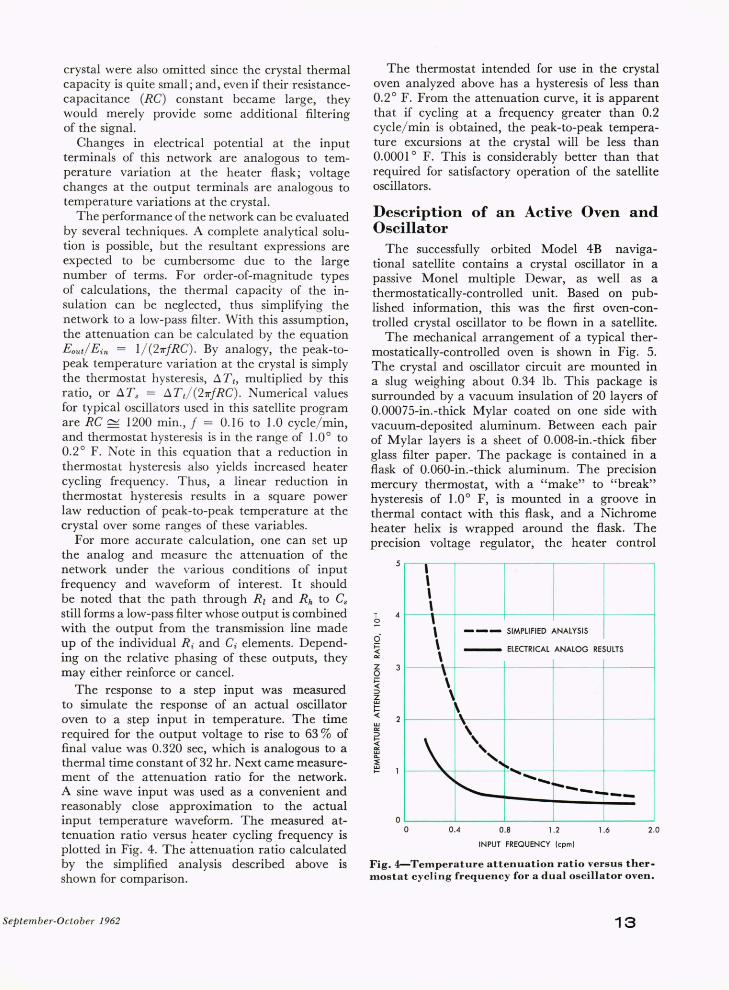
An electrical network analog3, 4 to this thermal system is shown in Fig. 3. Here, Cs is analogous to the metal slug III contact with the crystal,
INPUT (1 to 20 kc)
o
3.18 meg
1.0 meg
16-SECTION RC NETWORK
i "R;;n---', \\-- R;/~ ---' I \ \~~~'-~I~~--------O 1 18.9 k \ ~ 18 .9 k I
I I \ I OUTPUT SIGNAL
I C i /~f \ \ C I /~ I TI' I 0.D2~ \ } 0 .02~f I ~.35 p.f I -- I ~\ --~--~~I~--~--~----O L _____ J L ___ .J
Fig. 3-Electrical network analog of the dual oscill ator oven thermal system.
Rz is the thermal resistance of the leads connecting the crystal oscillator and the intermediate flask, Rh is the heat leak by radiation through the holes in the inner insulation, R i is the total thermal resistance of the inner layer of vacuum insulation, Ci is the total thermal capacity of the insulation, and n is the number of radiation shield layers. Note here that this analog network does not include the thermal resistance of the thermostat-toflask bond and the thermostat thermal capacity since they are both quite small. The quartz crystal thermal capacity and the thermal resistance path from the metal slug through the leads to the
3 A. J . Fisher, "Final E ngineering Report, Satellite S-45 Ionosphere Beacon Transmitter", NASA Marshall Space Flight Center, Report MTP-M-G & C-61-16, Mar. 10, 1961. 4 D. 1. Lawson and J . H. McGuire, "The Solution of Transient HeatFlow Problems By Analogous Electrical Networks" Institution 0/ Mechanical Engineers Proc. (A), 167, 1953.
APL Technical Digest
crystal were also omitted since the crystal thermal capacity is quite small; and, even if their resistancecapacitance (RG) constant became large, they would merely provide some additional filtering of the signal.
Changes in electrical potential at the input terminals of this network are analogous to temperature variation at the heater flask; voltage changes at the output terminals are analogous to temperature variations at the crystal.
The performance of the network can be evaluated by several techniques. A complete analytical solution is possible, but the resultant expressions are expected to be cumbersome due to the large number of terms. For order-of-magnitude types of calculations, the thermal capacity of the insulation can be neglected, thus simplifying the network to a low-pass filter. With this assumption, the attenuation can be calculated by the equation Eout/ Ein = 1/ (27TfRG). By analogy, the peak-topeak temperature variation at the crystal is simply the thermostat hysteresis, ~ T t, multiplied by this ratio, or ~ T s = ~ T t/ (27TfRG). Numerical values for typical oscillators used in this satellite program are RG r-v 1200 min., f = 0.16 to 1.0 cycle/ min, and thermostat hysteresis is in the range of 1.00 to 0.20 F. Note in this equation that a reduction in thermostat hysteresis also yields increased heater cycling frequency. Thus, a linear reduction in thermostat hysteresis results in a square power law reduction of peak-to-peak temperature at the crystal over some ranges of these variables.
For more accurate calculation, one can set up the analog and measure the attenuation of the network under the various conditions of input frequency and waveform of interest. It should be noted that the path through Rl and Rh to Gs
still forms a low-pass filter whose output is combined with the output from the transmission line made up of the individual R i and Gi elements. Depending on the relative phasing of these outputs, they may either reinforce or cancel.
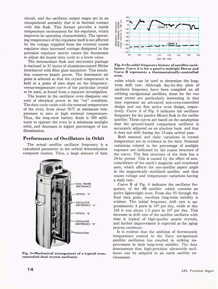
The response to a step input was measured to simulate the response of an actual oscillator oven to a step input in temperature. The time required for the output voltage to rise to 63 % of final value was 0.320 sec, which is analogous to a thermal time constant of 32 hr. Next came measurement of the attenuation ratio for the network. A sine wave input was used as a convenient and reasonably close approximation to the actual input temperature waveform. The measured attenuation ratio versus heater cycling frequency is plotted in Fig. 4. The ~ttenuation ratio calculated by the simplified analysis described above is shown for comparison.
September-October 1962
The thermostat intended for use in the crystal oven analyzed above has a hysteresis of less than 0.20 F. From the attenuation curve, it is apparent that if cycling at a frequency greater than 0.2 cycle/ min is obtained, the peak-to-peak temperature excursions at the crystal will be less than 0.00010 F. This is considerably better than that required for satisfactory operation of the satellite oscillators.
Description of an Active Oven and Oscillator
The successfully orbited Model 4B navigational satellite contains a crystal oscillator in a passive Monel multiple Dewar, as well as a thermostatically-controlled unit. Based on published information, this was the first oven-controlled crystal oscillator to be flown in a satellite.
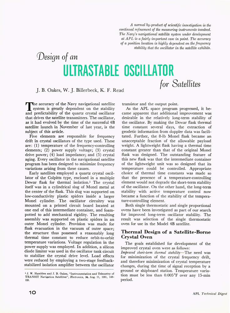
The mechanical arrangement of a typical thermostatically-controlled oven is shown in Fig. 5. The crystal and oscillator circuit are mounted in a slug weighing about 0.34 lb. This package is surrounded by a vacuum insulation of 20 layers of 0.00075-in.-thick Mylar coated on one side with vacuum-deposited aluminum. Between each pair of Mylar layers is a sheet of 0.008-in.-thick fiber glass filter paper. The package is contained in a flask of 0.060-in.-thick aluminum. The precision mercury thermostat, with a "make" to "break" hysteresis of 1.00 F, is mounted in a groove in thermal contact with this flask, and a Nichrome heater helix is wrapped around the flask. The precision voltage regulator, the heater control
5 , , , \
I 4 0
6 i= ~ Z 0 i= 4:
\ --- SIMPLIFIED ANALYSIS
\ - ElECTRICAL ANALOG RESULTS
\ I
\ I ::> Z
~ 4:
l I I \ w
'" ::> .....
ffi ~
\ I I
\ " ' ... "
" ~ .. , ......
~----!---o
o 0.4 0.8 1.2 1.6 2.0
INPUT FREQUENCY (cpm)
Fig. 4-Temperature attenuation ratio versus thermostat cycling frequency for a dual oscillator oven.
13
circuit, and the oscillator output stages are in an encapsulated assembly that is in thermal contact with this flask. This feature provides a stable temperature environment for the regulator, which improves its operating characteristics. The operating temperature of the regulator itself is not affected by the voltage supplied from the external coarse regulator since increased wattage dissipated in the precision regulator merely causes the thermostat to adjust the heater duty cycle to a lower value.
The intermediate flask and electronics package is enclosed in 31 layers of aluminum-coated Mylar interleaved with fiber glass insulation. This insulation conserves heater power. The thermostat set point is selected so that the crystal temperature is held at a point of zero slope on the frequencyversus-temperature curve of the particular crystal to be used, as found from a separate investigation.
The heater in the oscillator oven dissipates one watt of electrical power in the "on" condition. The duty cycle varies with the external temperature of the oven, from about 50 % at minimum temperature to zero at high external temperature. Thus, the long-term battery drain is 500 milliwatts to operate the oven in a minimum sunlight orbit, and decreases in higher percentages of sun illumination.
PerforInance of Oscillators in Orbit The actual satellite oscillator frequency is a
calculated parameter in the orbital determination computer routine. Thus, a large amount of data
"'JIII!!~- DUAL HEATER ELECTRONICS
CRYSTAL "A"
OSCILLATOR ELECTRONICS "A"
CRYSTAL " B"
OSCILLATOR ELECTRONICS- "B"
INSULATION
Fig. 5-Mechanical arrangement of a typical ovencontrolled dual crystal oscillator.
14
40
U 20 Zt1:iE Q:2co o-u.o <0- - 20 >-Jo ~ ~.:; - 40
ti ~ ~ - 60 ~z~ 5~: - 80
i' l
J'''''' J ~
.. -II ~ ~--.
,,'I CURVE A 1"- J Iv\"
CURVE B ~ ~ ~ - 100 u. ~ - 120 .- - --r--.... ~ -·I-~- 1--
- 140 95 105 115
I
125 135
DAY OF 1962
-1 I _1
145 155 165
Fig. 6-In-orbit frequency history of satellite oscillators. Curve A is for a passive multiple Dewar and Curve B represents a thermostatically-controlled oven.
exists which can be used to determine the longterm drift rate. Although day-by-day plots of oscillator frequency have been compiled on all orbiting navigational satellites, those for the two most recent are particularly interesting in that they represent an advanced non-oven-controlled design and our first active oven design, respectively. Curve A of Fig. 6 indicates the oscillator frequency for the passive Monel flask in the earlier satellite. These curves are based on the assumption that the ground-based comparison oscillator is accurately adjusted on an absolute basis and that it does not drift during the IS-min orbital pass.
Both seasonal and daily variations in crystal temperature are in evidence in the data. Seasonal variations related to the percentage of sunlight exposure are indicated by the coarse structure of the curve. The fine structure of the data has a 24-hr period. This is caused by the effect of noncoincidence of the earth's magnetic and rotational axes which affects the sun-satellite aspect angle in the magnetically stabilized satellite and thus causes voltage and temperature variations having a daily rate.
Curve B of Fig. 6 indicates the oscillator frequency of the 4B satellite which contains an active lightweight oven. From day 95 through the final data point, excellent long-term stability is evident. The initial frequency drift rate is approximately 4 parts in 10 9 per day, while at day 163 it was about 1.3 parts in 10 9 per day. This decrease in drift rate of the satellite oscillator with time is typical of high-quality quartz crystals, and further improvement is expected as the aging process continues.
It is evident that the addition of thermostatic temperature control to the Navy navigational satellite oscillators has resulted in striking improvement in their long-term stability. The da~a demonstrate that high-precision ultrastable oSClllators can be adapted to an earth satellite environment.
APL Technical Digest