Embed Size (px)
Citation preview

RD-A154 768 TEST EVALUATION OF THE HONEYWELL GG111± 1/1..SINGLE-DEGREE-OF-FREEDOM (SDF) STRAPDOWN GYROSCOPE(U)DEFENCE RESEARCH ESTABLISHMENT OTTAWA (ONTARIO)
UNCLASSIFIED N F VINNINS ET AL. OCT 84 DREO-TN-85-2 F/G 7/7 NL
EEEEEEE/h/hhhEIEEE.'.

. .1.0 .8.
*II1111 '. II112216, 136 2
I ii1.5 ~
MICROCOPY RESOLUTION TEST CHARTNATIONAL BUREAU OF STANDARDS-1963-A
............... ..... .. ... .. . --................. - . . . --. . . . . . .- . . . .. ' "" " .. . .*--' -.- '... . . . . . . . . . .. '"' "' " ""
I gl t I I (,(I , I Itjl\£!I(J t ,if t,
- -. 4. -4L',N&* Nional Defense
Defence natonale
TEST EVALUATION OF THE HONEYWELL GG 111SINGLE-DEGREE-OF-FREEDOM ISOF)
00 STRAPDOWN GYROSCOPE
by
If) M.F. Vinnins and R. Apps
<DTIC
, JUN 10 1985
BLIJ
DEFENCE RESEARCH ESTABLISHMENT OTTAWATECHNICAL NOTE 85-2
Canad "CaaaOttawa°
Ditnhbuka UnimiMft.Approw - 85 5 13 112
.. -- .. . . . . . . . . . . . . . ..
, National DtenseDefence ainl .... =,oo, O0,o~e -'--.':
":-. 'S
TEST EVALUATION OF THE HONEYWELL GGl11 '-ISINGLE-DEGREE-OF-FREEDOM (SDF"
STRAPOOWN GYROSCOPE
by
M.F. Vinnins and R. AppsElectromagnetics Section
Electronics Division
DTICLELECTE!ID - -l
B
DEFENCE RESEARCH ESTABLISHMENT OTTAWATECHNICAL NOTE 85-2
PCN October 198432G0I OttawaI s R B T O ST T M N A)
7 - r- , - o in u- -Distribu~Um,-: t.
,_ .r . ._ :_..'. , "'. '"''""' .' -'""".-' "" ." .""" ."". "7 " "• •", - , ,","--' " " " " " , , . . ., " •-.- •.. .. * S'" -
5. - ---,.' -. --. C " ,? . ," . ." . "' . ' - . ,- . " . " " o . .. . " ,
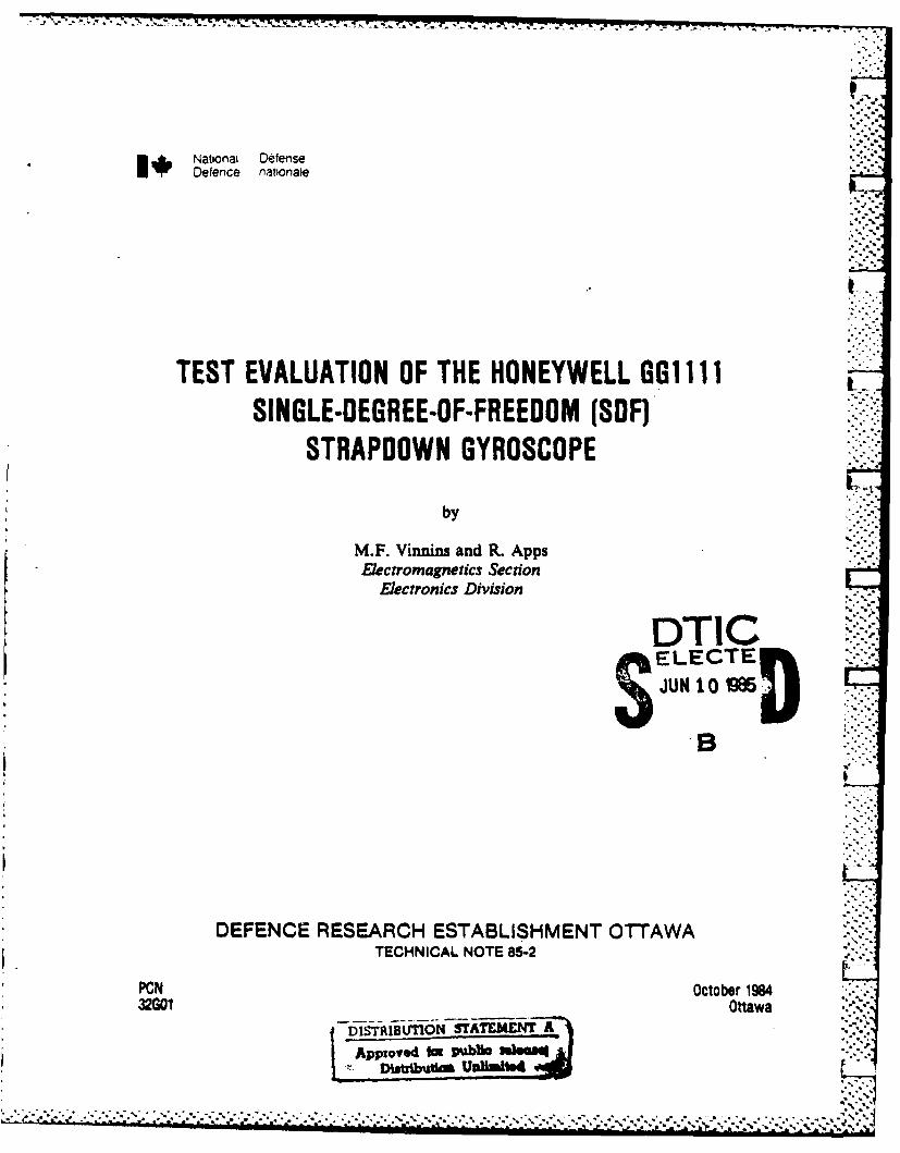
Abstract
Test results from the evaluation of a Honeywell GG1111single-degree-of-freedom strapdown gyroscope are presented. Testsinclude both static and constant-rate tests in servo and inanalog-torque-to-ba lance modes. Results of multi-position drift tests,drift stability, cool-down sensitivity, temperature sensitivity, torquegenerator linearity, scale factor stability and torque generatorsensitivity to input axis rate changes are presented, described anddiscussed.
R~sumd
On prisente lea r~sultats de l'Avaluation d'un gyroscope sansplate-forme stabilisae Honeywell GG11ll un seul degrg de libert4. On aeffectu4 des essais statiques et des essais k vitesse constante en moded'asservissement et par utilisation d'un signal analogique pour6quilibrer le couple. On prdsente, d~crit et Studie lea rdsultatsd'essais de ddrive I positions multiples, la stabilitf de ddrive, lasensibiliti au refroidissement, la sensibilitd thermique, la lindaritA dug~n~rateur de couple, la stabilitf du facteur d'6chelle et la sensibilitddu gndrateur de couple aux variations de la vitesse d'acchs en entrde.
STI
VkTIS Th'A
%S%
&To
, o A 'or.....
Unrii ea ' .
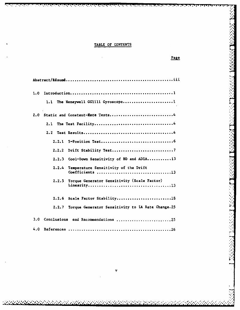
TABLE OF CONTENTS
Page
Abstract/Rhsumi ................................................. ii
1.0 Introduction .................... ......................... 1
1.1 The Honeywell GGllll Gyroscope ....................... 1 V
2.0 Static and Constant-Rate Tests ............................. 4
2.1 The Test Facility .................................... 4
2.2 Test Results .............................. .... 4
2.2.1 5-Position Test .......................... 6
2.2.2 Drift Stability Test ....................... 7
2.2.3 Cool-Down Sensitivity of BD and ADIA ........... 13
2.2.4 Temperature Sensitivity of the DriftCoefficients .................................. 13
2.2.5 Torque Generator Sensitivity (Scale Factor)Linearity ...................................... 13
2.2.6 Scale Factor Stability ............... .... 18
2.2.7 Torque Generator Sensitivity to IA Rate Change.25
3.0 Conclusions and Recommendations ......................... 25
4.0 References ............................................... 26
-,...--
. . . . . .. . .

-I.A LA1Z-V "1 7, - -. i a- . _ ~ *
I1
Test Evaluation of the Honeywell GGlli 44SDF Strapdown Gyroscope
1.0 INTRODUCTION
This report presents the results of an extensive series of testsevaluating the Honeywell GGllll, Single-Degree-of-Freedom (SDF) strapdowngyroscope. Tests were performed in both static and constant rateenvironments (see DREO TN 83-18) to measure drift coefficients, driftstabilities, torquer scale factor, scale factor linearity as well asthermal sensitivities. Scale factor linearity and stability underconstant rate inputs were evaluated using a Honeywell analog rebalanceloop.
Although gyroscopes of such quality are not usually employed asvehicle inertial navigators, it is felt that with proper characterizationof the error terms of the instruments, many of the errors can be modelledand compensated for in navigation software resulting in substantialimprovements in system performance. This is particularly applicable inintegrated systems where aiding sensors are available and low cost ishighly desirable.
This report will describe the Honeywell GGllll gyro, the test .-
facilities and the test results. All testing was performed within theDUEO Inertial Navigation Laboratory, a description of which can be foundin DUEO Report #895, The DUEO Inertial Navigation Laboratory:Development and Test Capabilities [A].
1.1. THE HONEYWELL GGlll1 GYROSCOPE
The Honeywell GGlll is a SDF, rate-integrating, floated gyro.Figure 1-1 shows the basic elements of a SDF gyro. The gyro depicted isof the rate-integrating type; that is, the deflection of the gyro elementrelative to the case is a measure of the integral of the angular velocityof the gyro about its sensitive (input) axis (i.e. change of angularattitude of the instrument). The 'damper' in the figure provides theprimary restraining torque on the instrument.
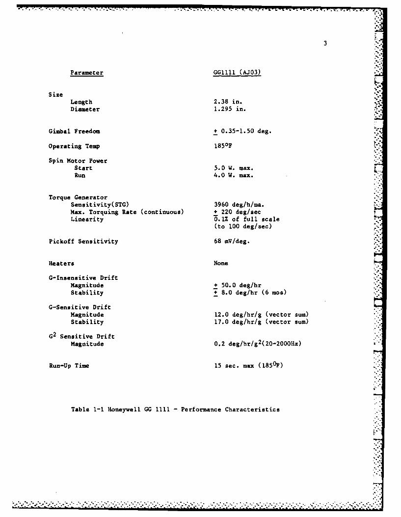
The performance specifications of the Honeywell model GGllll gyro
are given in Table 1-1. Note that this is a floated-type low gradeinertial instrument with very high bias and acceleration-sensitive driftsand relatively poor stability. Other instruments in this class includethe Lear Siegler model 1903 and Northrop model GI-G6. Typical
applications for this grade of gyroscope include short range missileguidance, attitude and heading reference systems and other forms oflow-cost inertial guidance.

2
GYRO ELEMENT
DAMPER
SIGAL
Figure 1-1 Essential Elements of a Rate Integrating Single-degree-of-freedom (SDF) Gyroscope
-_7 _7 L_ I7 9- Q A_ W. 1 X-T -T
3
Parameter GG1111 (AJO3)
SizeLength 2.38 in.Diameter 1.295 in.
Gimbal Freedom + 0.35-1.50 deg.
Operating Temp 1850F
Spin Motor PowerStart 5.0 W. max.LiRun 4.0 W. max.
Torque GeneratorSensitivity(STG) 3960 deglh/ma.Max. Torquing Rate (continuous) + 220 deg/sec 6Linearity 0.1% of full scale
(to 100 deg/sec)
Pickoff Sensitivity 68 mV/deg.
Heaters None
G-Insensitive DriftMagnitude + 50.0 deg/hrStability -8.0 deg/hr (6 mos)
G-Sensitive DriftMagnitude 12.0 deg/hr/g (vector sum)Stability 17.0 deg/hr/g (vector sum)
G2 Sensitive DriftMagnitude 0.2 deg/hr/g2(20-2000Hz)
Run-Up Time 15 sec. max (1850F)
Table 1-1 Honeywell GG 1111 -Performance Characteristics
* - -. .. . . . . .

4
2.0 STATIC AND CONSTANT-RATE TESTS
The major error terms investigated during these tests include bothG-sensitive and G-insensitive terms; bias drift (BD) andacceleration-sensitive drift about each instrument axis (ADIA, ADSRA andADOA, where IA - input axis, SRA- spin reference axis and OA - outputaxis). In addition, torque generator sensitivity (scale factor) and.temperature effects are also evaluated.
For all error terms, not only is the magnitude of interest but alsostability, repeatability, sensitivity to temperature or rate changes anddynamic effects such as linearity and transients.
The gyro was tested in two modes; inertial reference servo modewhere the motion table servo loop is used to drive the table to opposeearth rate and gyroscopic drift and torque -to-balance mode whereby the -
gyro float is nulled by the application of current to the gyro torquercoil by means of an electronic sensing and feedback circuit.
2.1 THE TEST FACILITY
The DREO Inertial Navigation Laboratory was designed to be a highlyversatile and flexible test facility for inertial components andsystems. The core of the facility is a Contravs-Goerz 2-axis motionsimulator (model 57CD) capable of aximuth rates from 0-1000 deg/sec.System support equipment includes variable frequency wheel and signalgenerator supplies controlled by a highly stable frequency source. Dataacquisition is accomplished automatically through an LSI-11microprocessor connected to all test equipment by way of an IEEE-488bus. Data reduction is performed on other site computers providinganalysis and plotting capabilities. A photograph of the laboratory isshown in Figure 2-1.
2.2 TEST RESULTS
The tests performed on the Honeywell GGll1 gyro include:
1. 5-position drift test (drift coefficients BD, ADIA, ADSRA, ADOA)
2. Drift stability test - IA vertical up- IA horizontal north
• I I . . . .. ... . . . .

5
0
U2 -
0.0 -.
U,0 -
-4

6
3. Cool-down sensitivity of BD and ADIA
4. Temperature sensitivity of BD, AD/A, ADSRA, ADOA
5. Torque Generator Sensitivity (Linearity) . -
6. Scale Factor Stability
7. Sensitivity to an IA Rate Change
All tests were performed in both inertial reference servo mode andanalog-torque-to-balance (ATBL) mode.
2.2.1 5-Position Test
The drift coefficients BD, ADIA, ADSRA and ADOA were extracted fromthe results of a 5-position test employing the following gyroorientations:
a) IA vertical up, OA vestb) IA horizontal north, SRA verticalc) IA horizontal north, SRA vertical downd) IA horizontal north, OA vertical upe) IA horizontal north, OA vertical down
The sign convention adopted (DREO TN 83-18) [B] assumes that instrumentdrift causes clockwise (CW) rotation of the inertial table top and thisis defined as positive drift.
For IA vertical up, we define
DRIFT - BD + ADIA
and for IA horizontal north, '
SRA up: DRIFT + BD + ADSRASRA down: DRIFT BD-ADSRAOA up: DRIFT - BD + ADOAOA down: DRIFT - BD - ADOA
r
-. .

4.~~~~~" t77 7.%-"-7- 7 L
7
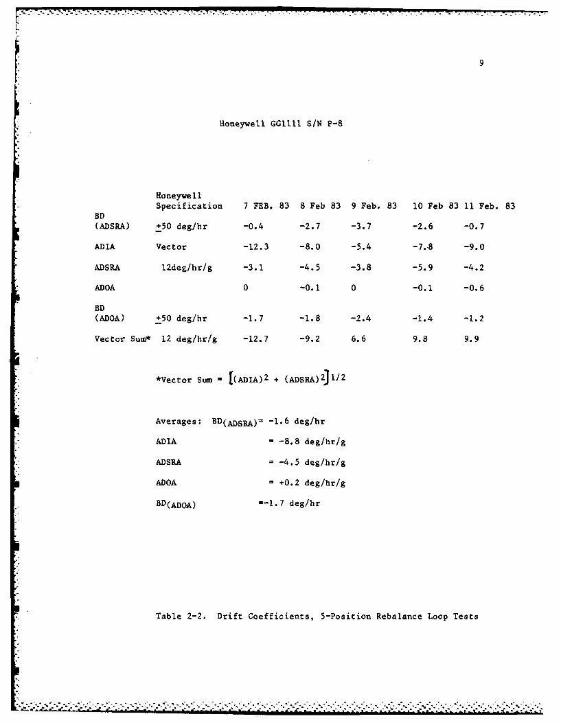
Table 2-1 lists the results of the 5-position test in servo mode
and Table 2-2 in analog-torque-to-balance loop mode. Results agree
favourably between the two modes although ADIA is different. This is
most probably due to the cool-down sensitivity of ADIA in this type of
instrument and is illustrated in section 2.2.3. Note that all drift
coefficients are well within the denoted Honeywell specifications but
that it is not, in fact, the magnitude of the coefficients that is so
important but rather repeatability and long-term stability.
2.2.2. Drift Stability Test
Drift stability tests were performed with the instrument stabilized
at its operating temperature. In servo mode, the table rate is sampled
over a 24 hour period for both IA vertical up and IA horizontal northorientations. In ATBL mode, the current to the rebalance loop is sampled
over a 24 hour period while the motion table is locked into each of the
previously mentioned axes orientations. It should be noted that the
results of the ATBL mode tests actually include the stability of the
rebalance loop electronics itself from the viewpoint of temperature
stability etc.
Figure 2-2 shows the results of a stability test in servo mode, IA - -
vertical up. The average drift over the 24-hour period is + 16.50 deg/hrwith a drift stability of 2.53 deg/hr.
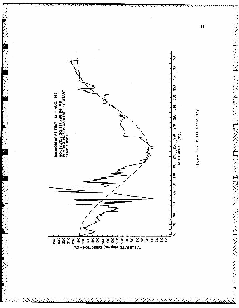
Figure 2-3 is the same test performed with IA horizontal north.
Note the 'cosine' outline to the drift; this is a result of instrument
misalignment on the table top resulting in a slight coning motion of the
input axis as the table top rotates in this orientation. The indicated
drift stability is worse than in Figure 2-2, approximately 6.0 deg/hr
except in the 110 to 170 degree table positions; the wild fluctuations in
instrument drift seem unreasonable and are, most likely, the effect of
external influences such as a problem in the motion table.
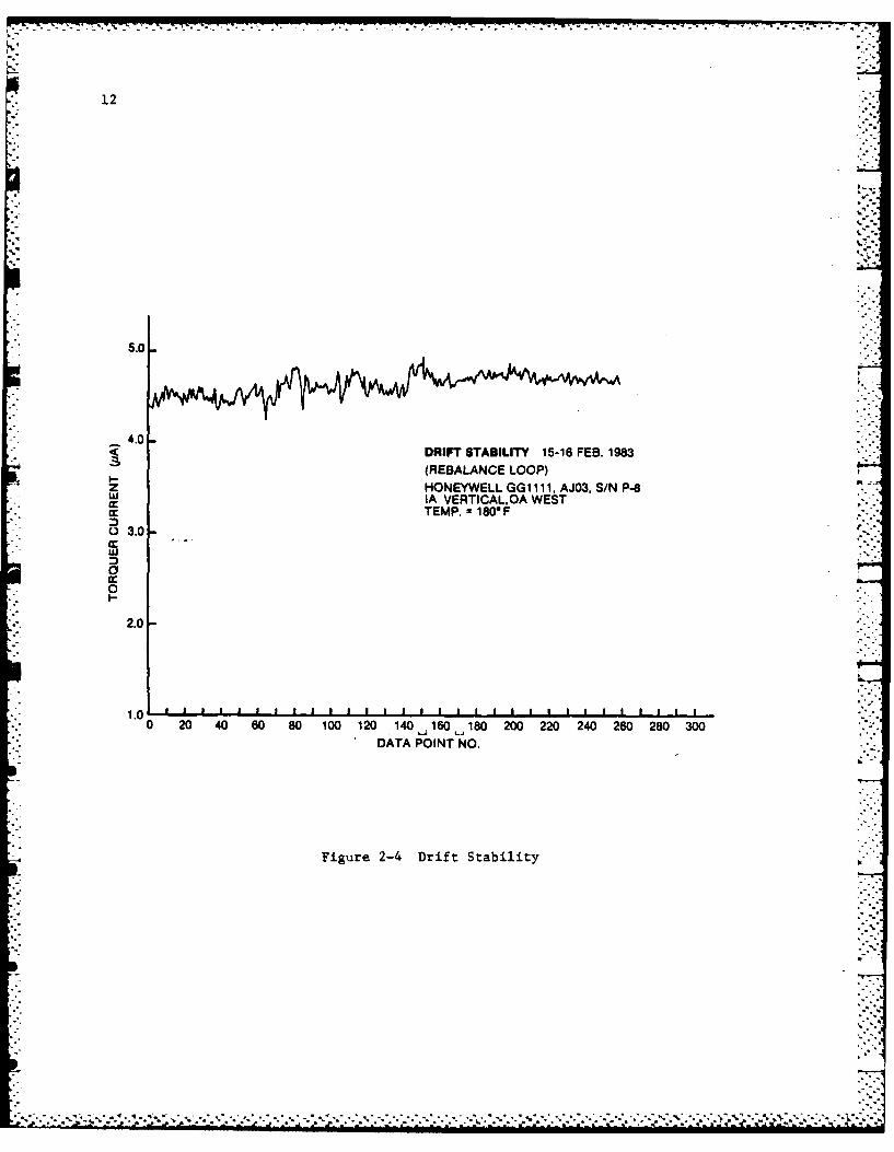
Results are similar when using the rebalance loop. Figure 2-4 show
the drift stability over 18 hours. From the figure:
IDC max - 4.926 pAmp
IDC min 4.248 i Amp L
IDC 0.678 x 10⁻⁶ Amp.
STG = 4024.7 deg/hr/ma (nominal)
Drift Stability - 2.73 deg/hr
.............................-..-..... .... ...

Honeywell GG1111 SIN P-8
HoneywellSpecification 11 Aug 82 18 Aug. 82 20 Aug. 82 24 Aug. 82
kDSRA) +50 deg/hr -1.3 -3.2 -7.0 -4.6
DIA Vector -2.2 -6.5 -2.7 -2.9
DSRA 12deg/hr/g -5.3 -5.0 -7.0 -.
DOA -+0.8 +0.7 +1.8
D
ADOA) +50 deg/hr -- 4.3 -3.7 -5.1
ector Sum* 12 deg/hr/g +5.7 +8.2 +7.5 +5.6
*Vector Sum =(ADtA)2 + (ADSRA)2)l/2
Averages: BD(A]D5 A)- -4.0 deg/hr
ADIA = -3.6 deg/hr/g
ADSRA -- 5.5 deg/hr/g
ADOA +1.1 deg/hr/g
BDQ&IDOA) =-4.3 deg/hr
Table 2-1. Drift Coefficients, 5-Position Servo Tests

U-U- a CO
m. LU - 4
0:)CA 0 CL-
0 (.Oh0 ~--u.
.C Z W( P0
E M4Z:;Z
U, 0
0
U,,
om
PU,
(VLU IN~didn uanuo0
. . .. . . . . . . .
21.
-1
00

20
U
z
I- &0
oil4
*-J<
Z>~
CJI
C.,7
IFI
is9
W Z§
I ~ i
CiC
-j a
LM xj z ca
cc CoLU UO
-- 4
w 0
x C0
00
O0
- C
18
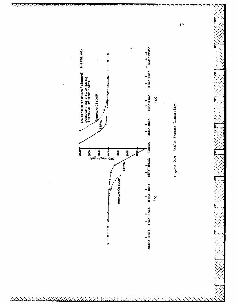
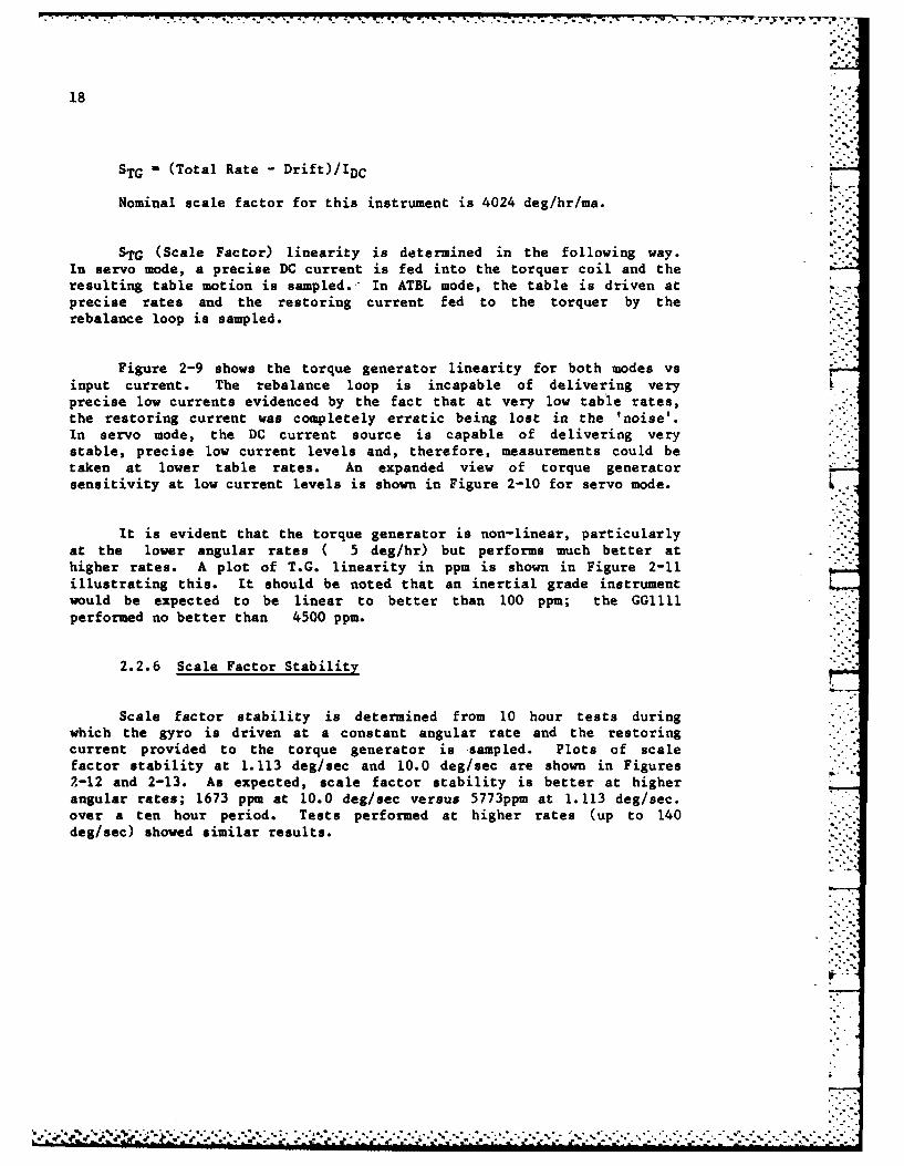
STG (Total Rate - Drift)/IDC
Nominal scale factor for this instrument is 4024 deg/hr/ma.
STG (Scale Factor) linearity is determined in the following way.In servo mode, a precise DC current is fed into the torquer coil and theresulting table motion is sampled.- In ATBL mode, the table is driven atprecise rates and the restoring current fed to the torquer by therebalance loop is sampled. -.
Figure 2-9 shows the torque generator linearity for both modes vsinput current. The rebalance loop is incapable of delivering veryprecise low currents evidenced by the fact that at very low table rates,the restoring current was completely erratic being lost in the 'noise'.In servo mode, the DC current source is capable of delivering verystable, precise low current levels and, therefore, measurements could betaken at lower table rates. An expanded view of torque generatorsensitivity at low current levels is shown in Figure 2-10 for servo mode.
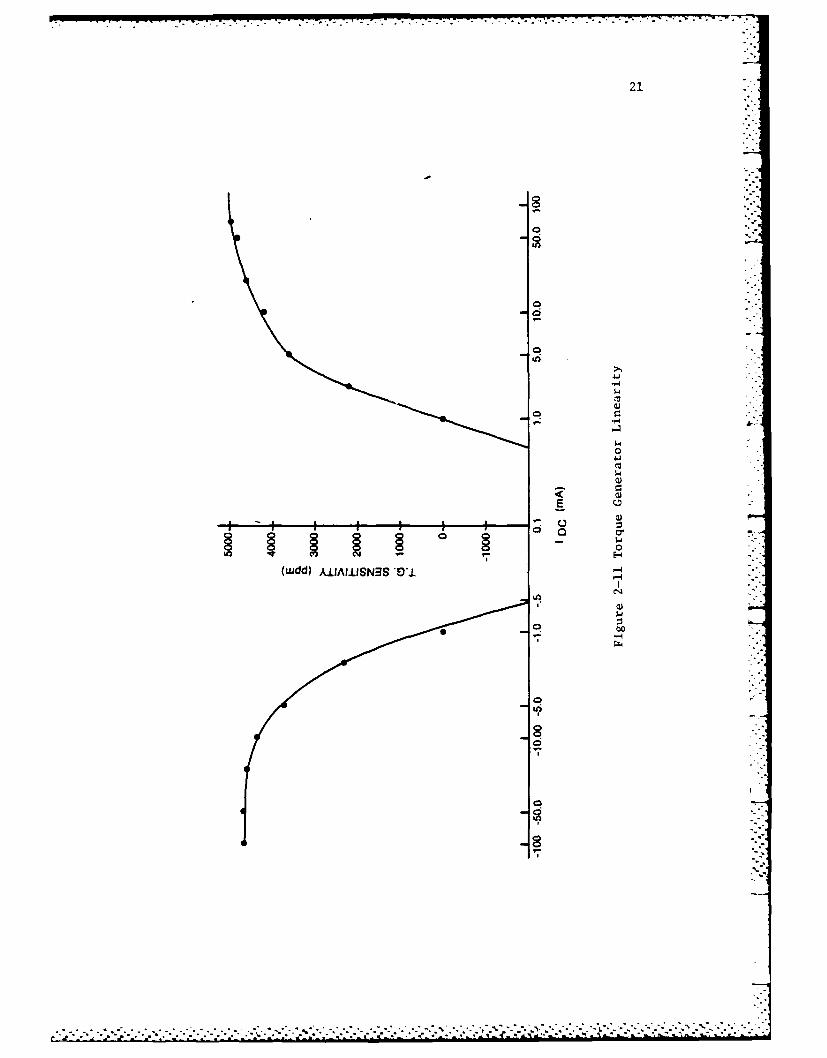
It is evident that the torque generator is non-linear, particularlyat the lower angular rates ( 5 deg/hr) but performs much better athigher rates. A plot of T.G. linearity in ppm is shown in Figure 2-11illustrating this. It should be noted that an inertial grade instrumentwould be expected to be linear to better than 100 ppm; the GG1111performed no better than 4500 ppm.
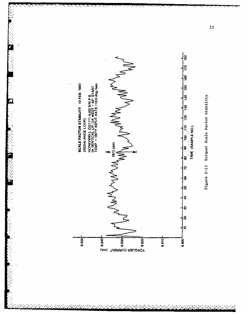
2.2.6 Scale Factor Stability
Scale factor stability is determined from 10 hour tests duringwhich the gyro is driven at a constant angular rate and the restoringcurrent provided to the torque generator is -sampled. Plots of scalefactor stability at 1.113 deg/sec and 10.0 deg/sec are shown in Figures2-12 and 2-13. As expected, scale factor stability is better at higherangular rates; 1673 ppm at 10.0 deg/sec versus 5773ppm at 1.113 deg/sec.over a ten hour period. Tests performed at higher rates (up to 140deg/sec) showed similar results.
............................

17...
2.HONEYWELL GG1111, AJO3, S/N P-8
1 SERVO MODE
0- 80
-2- -
-4
h.
- - 2....
O%"ADSRA
7 / ADIA
-10
-11
18 160 170 180 190
TEMPERATURE (°F)
Figure 2-8 Temperature Sensitivity of BD, ADIA, ADSRA
p p p . * p p.. * . ...- - . '--pp p. . -".p.o'. .'-'
* ~ P***'P',*PPP'*'*~P*S .p--':*-'p. -.. '.-.'-.- .- -- p. ...

16
HONEYWELL GGI 111. AJ03. S/N P-80-
-2 s
3.2 dog/hr
ca -77.7 deg/hr/g
-11
-12 IAUG 82 JUN 83 MAR 83 MAR 83 MAR 83 MAR 83 MAR 83 MAR 83
TIME
Figure 2-7 Cool Down Sensitivity of BD, ADIA

15
DRIFT STABILITY 16-17 FEB. 19834.20-
(REBALANCE LOOP)
HONEYWELL GG1111 S/N P-84.00- IA HORIZ. NORTH, SRA VERTICAL UP,
450 START( 380TEMP. 1 180 F
.80
u3.60-
~3.40O
~3.20-0
3.00
2.80
2.60
45 65 85 105 125 145 165 185 205 225 245 265 285 305
TIME (SAMPLE*NO.)
Figure 2-6 Drift Stability

14
5.0DRIFT STABILITY 17-18 FEB. 1983(REBALANCE LOOP)HONEYWELL GG1111, AJ03. S/N P-8IA HORIZ. NORTH, OA VERTICAL
4.0 TEMP. =180* F
w
0
2.0
0 20 40 60 80 100 120 140 180 180 200 220 240 260 280 300
DATA POINT NO.
Figure 2-5 Drift Stability
:2r

13
Similar results are shown in Figures 2-5 and 2-6 where the driftstabilities are 1.747 deg/hr and 4.93 deg/hr respectively although inFigure 2-6, a sudden shift is evident. The reason for this sudden changeis not clear although the drift seems to reassume a similar pattern afterthe disturbance indicating that the effect is likely external to theinstrument.
In summary, a drift stability of less than 6.0 deg/hr would seem to
be indicated for this instrument. This also is within Honeywellspecifications.
2.2.3 Cool-Down Sensitivity of BD and ADIA
Both BD and ADIA are, in general, sensitive to temperature changesand cool-down. The 5-position test was repeated several times betweenwhich the gyro was turned off, cooled to room temperature and thenreheated. A plot of cool-down sensitivity is shown in Figure 2-7. Thebias drift changes by as much as 3.2 deg/hr and ADIA by 7.7 deg/hr/gbetween cool-downs. This unfortunately implies very poor instrumentrepeatability.
2.2.4 Temperature Sensitivity of the Drift Coefficients
Not only are several of the drift coefficients sensitive tocool-down but also to changes in operating temperature. The operatingtemperature as supplied by the manufacturer is usually the optimumtemperature for the instrument with respect to minimizing driftcoefficients.
The Honeywell gyro was run at three different temperatures,1700R, 180OF and 190F without cool down between changes. Figure2-8 shows plots of BD, ADIA and ADSRA with respect to operatingtemperature. As shown in 2.2.3 BD and ADIA are most sensitive totemperature; ADIA changes by 11.2 deg/hr/g and BD by 2.5 deg/hr. Ingeneral ADOA is unaffected by cool down or temperature change.
2.2.5 Torque Generator Sensitivity (Scale Factor)Linearity
From the random drift tests, one can calculate the Torque GeneratorSensitivity (STG), sometimes referred to as DC scale factor. In the IAvertical up orientation, Random Drift - BD+ADIA. The average randomdrift from the tests performed was +16.626 deg/hr and, by definition,
12
4.0*
DRIFT STABILITY 15-16 FEB. 1983(REBALANCE LOOP)
z HONEYWELL GG1111, AJ03, S/N P-8LU IA VERTICALICA WEST
cc TEMP. =1800 F
0 30
I-
2.0
0 20 40 60 80 100 120 14091609180 200 220 240 260 280 300DATA POINT NO.
Figure 2-4 Drift Stability
0-04
OU- jCDv
a4 -Lu
Ca0
CM -4
N' CI- N4.1 - -
MO NOLOM~a ('4/*BP) 3l~ldTISV

u .*i I * 'ii 1111. II I* * II j~iqJILU LEU'LIUU~I~IWU~EL~UJI ~ -.-. .- ~..-
10
0J
CM,
-00
cLL.,
2* CI-Y
0 L0
C',
'U -o
-H
oN CY -4N
MO NLLOSIC (Jt4/OGP)3.LVd 3-1IV-
Honeywell GGIIII S/N P-8
HoneywellSpecification 7 FEB. 83 8 Feb 83 9 Feb. 83 10 Feb 83 11 Feb. 83
BD(ADSRA) +50 deg/hr -0.4 -2.7 -3.7 -2.6 -0.7
ADIA Vector -12.3 -8.0 -5.4 -7.8 -9.0
ADSRA 12deg/hr/g -3.1 -4.5 -3.8 -5.9 -4.2
ADOA 0 -0.1 0 -0.1 -0.6
BD(ADOA) +50 deg/hr -1.7 -1.8 -2.4 -1.4 -1.2
Vector Sum* 12 deg/hr/g -12.7 -9.2 6.6 9.8 9.9
*Vector Sum [(ADIA)2 + (ADSRA)2JL/2
Averages: BD(ADSRA) f -1.6 deg/hr
ADIA - -8.8 deg/hr/g
ADSRA = -4.5 deg/hr/g
ADOA = +0.2 deg/hr/g
BD(ADOA) --1.7 deg/hr
Table 2-2. Drift Coefficients, 5-Position Rebalance Loop Tests
23
La
.0 o . J.Ho ~ - 9-4
00
0 -1 o
Sw z ~0J<Q
-w
- 0.- i
w luxa: 0
-4
00
0c
02r-4
Q0 0 0 0m
*. . . . . .. .. CR C*
24
30-
29-
28-
27.-" 26
V -0.5 mA for 5 min.
30 mA for 5 min.
+ 24
Z 23-
S22-
'21 -
20-
il 19 -
0 2 4 6 8 10 12, 14 16 18 20 22 24 26 28 30
TIME (min.)
Figure 2-14 Effect of an IA Rate Change
25
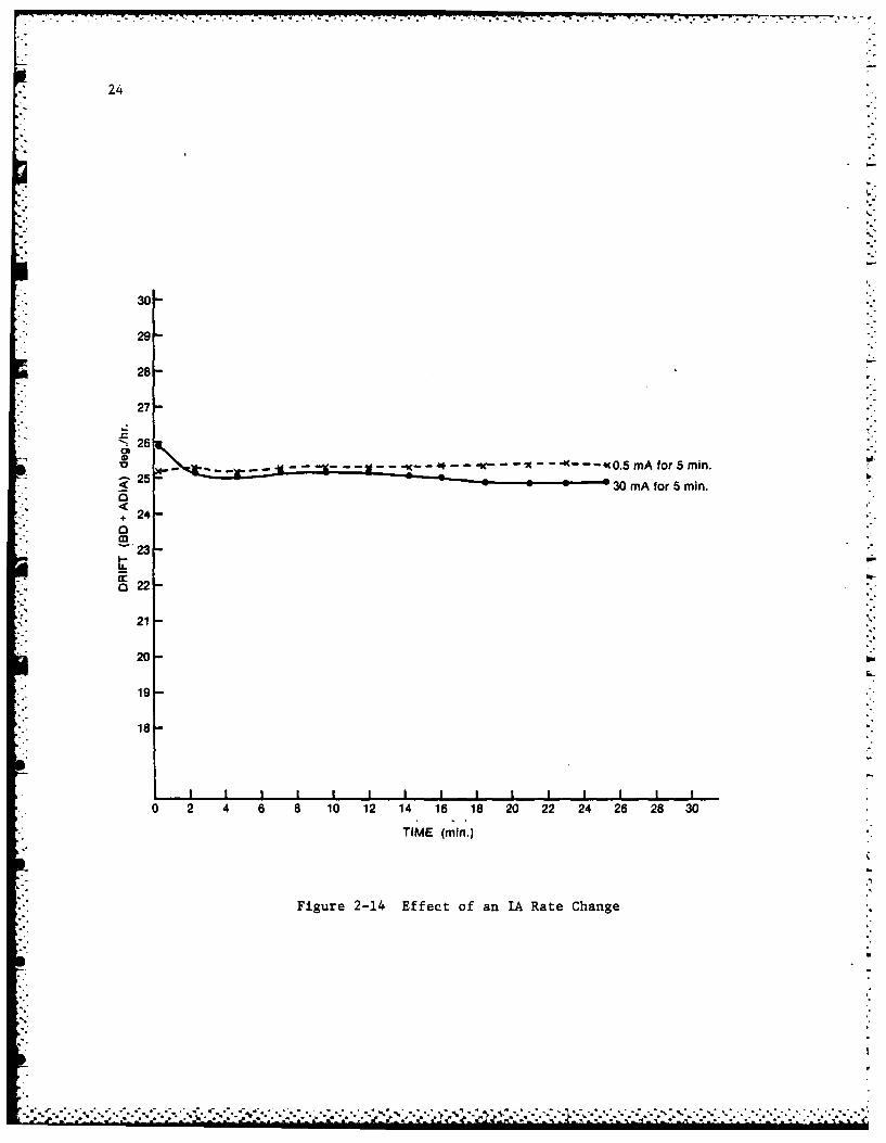
2.2.7. Torque Generator Sensitivity to IA Rate Change
In a strapdown instrument, sudden changes in dynamics (angularrates) cause large changes in restoring current to the torquer coil.These changes cannot be instantaneous and it is likely that sometransient effect due to torquer coil heating or hysteresis will occur.To investigate the effect of sudden rate changes on instrument drift aseries of tests was performed. With the gyro in the IA vertical uporientation, the table was driven at a constant rate (30 deg/sec) for 5minutes and then stopped. The instrument drift was then measured for 30minutes to detect any transient effects. Figure 2-4 shows the long term(30 minute) effect of rate change and it is evident that there is nosignificant effect. In fact, the transient disappeared in all caseswithin one minute of each change and very often within a few seconds.Unfortunately, the data recording system was not capable of samplingquickly enough to obtain the transient data. It should be noted htateven seemingly short transients in instrument drift will result insubstantial system errors, particularly under severe dynamics.
* 3.0 CONCLUSIONS AND RECOMMENDATIONS
The Honeywell GGI11 gyroscope performed within the statedspecifications in a static environment:
a. Drift stability was determined to be 6.0 deg/hr.
b. Bias and g-sensitive drift coefficient amplitides were less than4.5 deg/hr and 12 deg/hr/g respectively.
c. Both BD and ADIA showed high sensitivity to cool down andoperating temperature changes.
The torque generator was found to be non linear, particularly at lowangular rates (45 deg/sec). At higher rates (5 deg/sec to 140 deg/sec),performance improved. Scale Factor stability was also poor at low ratesbut, again, improved at higher rates; typically to less than 2000 ppm.The torque generators showed no long term shift in sensitivity due to IArate changes but did demonstrate a short transient, typically less than10 seconds.
In conclusion, the instrument qualifies as a low grade gyroscopeuseable in such strapdown applications as short range missile guidance.Due to its high sensitivity to temperature and cool-down, it is unlikelythat this gyro could be used in AHRS or navigation applications.
'.............., .-j .- --.......................................,................°...-............ ............... . ...... ......... ,......... ..
26
4.0 REFERENCES
A) 'The DREO Inertial Navigation Laboratory: Development and TestCapabilities', M. Vinnins, DREO Report # 895, June 1984.
B) 'Procedures for Static and Constant-Rate Tests on aSingle-Degree-of-Freedom (SDF) Strapdown Gyroscope' R. Apps andM. Vinnins, DREO TN 83-18, October 1983.
V..

27
A'IS',- 768UNCLASSIFIEDDOCUMENT CONTROL DATA -R & 0
' a I~~Seci-t~ly classiliation of title. body of abstract and indexuing annotation mnust hie entered w.iteii the overail ilowmiem s% classified)
1 ORIGINATING ACTIVITY 2a. DOCUMENT SECURITY CLASSIFICATIONDefence Research Establishment Ottawa UCASF~
2b GROUP
a. DOCUMENT TITLES Test Evaluation of the Honeywell GG11ll Single-Degree-of-Freedom (SDF) StrapdowGyroscope
4. DESCRIPTIVE NOTES [Type of report and inclusive dates)l
Tech Note5. AUTHORISI 11-ast name. first name, middle initial)
Vinnins, Michael F. and Apps, R.G.
6. DOCUMENT DATE Oc 947a. TOTAL NO. OF PAGES 7b. NO OF REFS
8a. PROJECT OR GRANT NO. 9a. ORIGINATOR'S DOCUMENT NUMBERISI
32G01
Bb. CONTRACT NO. 9b. OTHER DOCUMENT NO.(S) (Any other numbers that may beassigned this documentl
10. DISTRIBUTION STATEMENT
Unlimited Distribution
11 SPPLEENTRY NTES12. SPONSORING ACTIVITY
13. ABSTRACT
iTest results from the evaluation of a Honeywell GG1111 Single-Degree-of-FreedoIStrapdown Gyroscope are presented. Tests include both static and constant-rate tests in servo and in analog-torque-to-balance modes. Results of multi-position drift tests, drift stability, cool-down sensitivity, temperaturesensitivity, torque generator linearity, scale factor stability and torquegenerator sensitivity to IA rate changes are presented, described and discusse.
'7- 16

*~~~~~~7 _ w 7-7 ~ .--- ...
28
UNCLASS IFIED
KEY WVORDS
s-'GYROSCOPE&
STRAPDONHONEYWELL GG1111
INSTR UCT IONS
IORIGINATING ACTIVITY Enter the name and address of Che 9b. OTHER DOCUMENT NUMBERISI If the document has boonorganization issuing the document, assigned any other document numbers eoithejr by the originator
or by the soorl. also enter this numberls).2a. DOCUMENT SECURITY CLASSIFICATION Enter the overall
iecurty classif~cation of the document including special warning 10. DISTRIBUTION STATEMENT Enter any limitations on.rswhenever applicable. further dissemination of the document. other than those imposed
by security classification, using standard statements such as.2b. GROUP Enter security reclassification group number. The three
groups are ceained in Appendix 'Mof the ORB Security Regulations. III "Qualified requesters may obtain copies of this
3. DOCUMENT TITLE Enter the complete document title in ail document from their defence documentation centercaptitletters. Titls n all cases should be unclassified. Ifs a(21 "Announcement and dissemination 0f this documentgulf iciently descriptive title cannot be selected without classifi- is not authorized without prior approval fromcation, show title classification with me usudi one-cakital- letter originating activity30breviation inl parentheses rnmediately roilowing the title.
11. SUPPLEMENTARY NOTES Use for additional explanatory4. DESCRIPTIVE NOTES. Enter the category of document. e.g. notes.
ecnclreplort, technical note or technical letter. if appropri-ate, enter the type of document. e.g. interim, progress. 12. SPONSORING ACTIVITY Enter the name of the departmentalsummary, annual or final. Give the inclusive dates when a project office or laboratory sponsoring the research andsoecilic reborting period is covered, development. Include address.
5. AUTHORISI: Enter the namelsl af aulhortsf s shown on or 13. ABSTRACT Enter an abstract giving a brief and factuaiin the document. Enter last name, first name, middle nital. summary of 'the document, even though 't may also appearIt moiinary. showy rank. The name of the orincipal author is an elsewhere in the body of the document itself. It is highlyaisdute minimum requirement. desirable that the abstract of classified documents be uflclassi-
fled. Each paragraph of the abstract shall end with an6. DOCUMENT DATE. Enter the date (month. year) of indication of the security classification ol the information
Esfafmishmer approval for publication of the document. in the paragraph (unless the document itself sn uinclassified) 3represented as ITS). ISI. IC). (RI, or (U).
7a. rOTAL NUMB8ER OF PAGES The total age count shouldfollow normal pagination procedures. i'a.. enter the number The lenlgth of the abstract should be limited to 20 single-spacedof pages containing information, standard typewritten irnes. 71 z ncmes long
7b. NUMBER OF REFERENCES. Enter the totai number of 14. KEY WORDS. Key words are technically meaningful terms orreferences Cited in tho document, short phrases that characterize a documenit and Could be helpful
in cataloging the document. Key words should be selected soBa PRO.IECT OR GRANT NUMBER It appropriate. enter the that no security classification ins required. Identifiers. such as
aactlicabie reseatch and Jeveloomont project or grant number eQuboment model designation. trade name, military project codeu.nder iNsich (he document was written, name, geographic location. may be u"ed as key words but will
be followed by an indication of technical contest.3b. CONTRACT N4UMBER It aporooriate. enter the aiplicable
numbter under wnich the dlocurment Was wr It ten.
9a. ORIGINATOR'S DOCUMENr NUMBERISI Enitr theofticimi Iocumtnt number by which the document wil oeijoitiiswd sncl controlled-t by the oigiiiaiing activinty This
number nust be unique to This docuiment.
.........................

- - - - - - -.. . ,
FILMED
7-85
DTIC
[[ a>~ ~ .*. ~ * * r*. .. .. * * * * - - - - - - - - - . .* . I "