Embed Size (px)
Citation preview

STATION WORKING RULESOF
BARUVA STATIONTO SUIT SI PLAN No. 21020 ALT “D”
KHURDA ROAD DIVISION
EAST COAST RAILWAY

(T.LAHIRI) (D.NAYAK)DSTE/KUR DOM/KUR
EAST COAST RAILWAYKHURDA ROAD DIVISION
NO. 31STATION WORKING RULES OF BARUVA STATION
BG Station.Date of Issue: 08.07.10
Date brought in force: 09.07.10NOTE: -The Station Working Rules must be read in conjunction with General & Subsidiaryrules, Operating Manual and Block Working Manual. These rules do not in any waysupersede any rules in the above books.
1. STATION WORKING RULE DIAGRAM:The Station Working Rule diagram No. SI/WRD/21020 based on CSTE/East CoastRailway and Signal Interlocking Plan No. SI/21020 ALT “D” shows the completelayout of the yard, siding, normal position of points, the Signalling and Interlockingarrangements, Gradients and Level Crossings within the station limits. This must bereferred to for giving details of the point numbers and signals when reportingaccidents.
2. DESCRIPTION OF STATION2.1. LOCATION
BARUVA (Code: BAV) is a ‘B’ class four lined station on the Howrah –Visakhapatnam Main line Double line electrified (BG) section of East Coast Railway.It is situated at Km.653.734 from Howrah. The station is provided with standard IIIInterlocking and equipped with Central Panel/VDU and Multiple Aspect Colour Lightsignals. The station is worked under Absolute Block System of GR & SRs.[Refer GR. 8.01(1)a, b, 2(b), 8.03(1), a, b, c(ii), 8.05(2)(3) & 8.06, 8.14, 8.15, 8.16]
2.2. BLOCK STATIONS, IBH, IBS ON EITHER SIDE AND THEIR DISTANCE ANDOUTLAYING SIDINGS:
2.2.i. BLOCK STATIONS ON EITHER SIDE AND THEIR DISTANCES:-BARUVA (Code: BAV) station is situated between SOMPETA (code-SPT) in theNorth side at a distance of 9.3KM and MANDASA ROAD (code-MMS) in the Southside at a distance of 9.3KM.
2.2.ii. IBH/IBS/OUT LYING SIDING/DK STATION:-NIL.
2.2.iii PASSENGER HALT:-NIL.
2.3.a. BLOCK SECTION LIMITS ON EITHER SIDE OF THE STATION ON DIFFERENTDIRECTIONS :
Between Stations The Point from which the‘Block Section’ Commences
The Point at which the‘Block Section’ end
BAV-MMS Up Direction Up Advanced starter signalNo.11 of BAV station
Up BSLB on Up line ofMMS
MMS-BAV DN Direction Down Advanced Startersignal No.14 of MMS station.
The outer most facingpoint 18A of BAV.
SPT-BAV UP Direction Up Advanced starter signalNo.13 of SPT station
UP BSLB on UP line ofBAV.
BAV-SPT DN Direction Down Advanced Startersignal No.12 of BAV Station
Outer most point no. PointNo.22A of SPT.
b. STATION SECTION:-

SWR of BAV Page No. 2
(T.LAHIRI) (D.NAYAK)DSTE/KUR DOM/KUR
Station Section The Point from which the‘Station Section’ Commences
The Point at which the‘Station Section’ end
Up Line Up Block Section Limit Board onUp line of BARUVA
Up advanced starter no.11of BARUVA
Dn Line Outer facing point No.18A onDown line at VSKP end ofBARUVA
Down advanced starterno.12 of BARUVA.
c. STATION LIMITi. UP LINE
Up Distant signal to UP Advanced starter signal No.11.
ii. DOWN LINEDN gate signal of L.C at Km. 655/27-29 cum DN distant signal of BAV to DownAdvanced starter signal No.12.
2.4 a) GRADIENTS WITHIN STATION LIMITS:i) TOWARDS HWH END (UP LINE)
From To GradientCSB CH: 474.0 M LevelCH: 474.0 M CH: 784.0M 1 in 437 FCH: 784.0M CH: 1214 M LevelCH: 1214 M CH: 2674.0M 1 in 1200 ‘F’CH: 2674.0M Towards Block Section 1 In 150 F
ii) TOWARDS HWH END: (DOWN LINE)From To GradientCSB CH: 377.51 M LEVELCH: 377.51 M CH: 786.546 M 1 in 881.54 ‘F’CH: 786.546 M CH: 947.55 M 1 in 242 ‘F’CH: 947.55 M CH: 1004.0 M LEVELCH: 1004.0 M CH: 1214.0 M 1 in 200 ‘F’CH: 1214.0 M CH: 1684. 0M 1 in 1200 ‘F’CH: 1684. 0M Towards Block Section 1 in 500 ‘F’
b) TOWARDS VSKP END: (UP LINE)From To GradientCSB CH: 1116.0 M LEVELCH: 1116.0 M CH: 2066.0M 1 in 770 ‘R’CH: 2066.0M CH: 2526.0 M 1 in 277 ‘R’CH: 2526.0 M CH: 3066.0 M LEVELCH: 3066.0 M Towards Block Section 1 in 777 ‘R’
TOWARDS VSKP END: ( IN DOWN LINE)From To GradientCSB CH: 1386 M LEVELCH: 1386 M CH: 2936.0 M 1 in 1776 ‘R’CH: 2936.0M CH: 3066.0 M LEVELCH: 3066.0 M CH: 3246.0 M 1 in 200‘R’CH: 3246.0 M Towards Block Section LEVEL

SWR of BAV Page No. 3
(T.LAHIRI) (D.NAYAK)DSTE/KUR DOM/KUR
2.5. LAYOUT:The station is provided with four running lines in the Main yard (namely Down LoopLine, Down Main Line, Up Main Line, Common Loop Line), and Two non running linei.e Goods siding & Hot Axle siding.
a.i. GOODS SIDING:The Goods siding at VSKP end of the yard with both side entry is taking off fromCommon Loop (Line No.4). The entrance point and corresponding derailing switchare coupled and operated by an arc lever at site. Both the entrance points are fittedwith hand plunger locks. These hand plunger locks are unlocked by Goods sidingkeys P1 & P2 & released by pressing the button No.24 and common group transbutton provided on panel/VDU at SM’s office. Reception signals (i.e. 1A. C1A.in Updirection and 2C. C2C. in Down direction) and shunt signal Nos.SH3A, SH4B andsignal No.5 & 8 are electrically interlocked in such a way that these signals cannot betaken ‘OFF’ if the Goods siding key is taken ‘OUT’ from the RKT provided at Goodssiding location at site.
ii. HOT AXLE SIDINGThe hot Axle siding at HWH end of the yard is taken off from line No.1( DN loop). Theentrance point & corresponding derailing switch are coupled & operated by an arclever at site. The entrance point is fitted with hand plunger locks. The hand plungerlock is unlocked by Hot Axle siding key ‘Q1’ & released by pressing the button No.25 & common group trans button provided on panel/VDU at SM’s office. Receptionsignals ( i.e. 2A, C2A in DN direction) & shunt signal No.3D & signal No. 6 areelectrically interlocked in such a way that these signals can not be taken ‘off’ if theHot Axle siding key is taken ‘OUT’ from the RKT provided at Hot Axle siding locationat site.
b. PLAT FORMSi) Line No. 1 (Down Loop) : H.L.P.F.ii) Line No. 2(Dn Main) : H.L.P.F.iii) Line No. 3 (Up Main) : R.L.P.F.iv) Line No. 4(Common Loop) : R.L.P.F
2.5.1. RUNNING LINES, DIRECTION OF MOVEMENT & HOLDING CAPACITY IN CSL:DIRECTION OF TRAFFIC:The trains coming from SPT end are Up trains and the trains coming from MMS endare Down trains.
2.5.2. HOLDING CAPACITIES IN CSL:Line No.1 Down Loop 692.6 M (Electrified). From starter to SBLine No.2 Down. Main 725.3 M (Electrified). From starter to SBLine No.3 Up Main 753.3 M (Electrified). From starter to SBLine No.4 Common Loop 725.5 M (Electrified). From starter to starter
2.5.3. NON RUNNING LINES:1. Goods Siding 81.5 M (CSL) (Electrified). From AC to AC2. Hot Axle siding 32.25 M (CAL) (Electrified). (AC to DE )
(a) ANY SPECIAL FEATURES IN THE LAYOUTNIL
(b) SPECIAL RESTRICTIONS:i) Shunting in the face of an approaching train is prohibited.ii) Hand shunting/fly shunting is prohibited at both ends of the yard.iii) The over run line must not be used for stabling of vehicle or harboring an engine with
or without vehicle.

SWR of BAV Page No. 4
(T.LAHIRI) (D.NAYAK)DSTE/KUR DOM/KUR
iv) Down Trains running through over common loop at this Station is strictly prohibited.In case, it is unavoidable to pass through the train admitted over common loop, itshould be brought to a stop at the Starter Signal before the same is taken “OFF”.
v) Shunting is not permitted unless the engine is leading towards the falling gradient.
[c] SPECIAL INSTRUCTIONS:i. Up & Down Mainlines are track circuited whereas Down Loop & Common Loop are
Axle countered. In case of failure of track circuit/Axle Counter, the clearance of theconcerned line should be ensured physically before a train is piloted.
ii. For receiving Up and Down trains on Common loop (Line No.4), the SM on duty shallensure that the over run line is clear of all obstructions even though the over run linefalls in trailing direction.
iii. Whenever a non signal movement has taken place over a point operated by motorwhether facing or trailing direction the SM on duty shall operate the points to normaland reverse setting for the purpose of setting the point. After the indication iscorrectly available, the facing and trailing points shall be clamp further movementmay be permitted over the points.
iv. Movement of non-insulated push trolley is prohibited between BAV-SPT and BAV-MMS section vide SR 15.25.04(c).
v. In case of failure of Digital Axle Counters provided for monitoring Block Section atboth end, the resetting should only be initiated for normalising the Block Instrumentafter ensuring complete arrival of the train by physical verification of Last Vehicle bySM on duty.
vi. Speed over turn outs on UP loop line No-1 (common loop) and DN loop i.e line No-4is 30 KMPH as per CRS sanction No-694 Dtd. 24/09/2009.
2.6 LEVEL CROSSINGS:i) There is a mid section ‘A’ class interlocked level crossing gate situated at Km.
657/27-29 (UP) and Km. 657/30-28 (DN) at VSKP end of the Station yard & directlyoperated by means of a winch from Gate Lodge. Telephone communication isprovided between the Gate lodge and the SM’s office of BAV.
ii) There is a ‘SPL’ class interlocked level crossing gate situated at Km. 655/27-29 (UP)and Km. 655/30-28 (DN) between Down Distant Signal-Cum-Dn Gate Signal and UpGate signal of L.C. gate at KM. 655/27-29 at VSKP end of the Station yard & directlyoperated by means of a winch from Gate Lodge. Telephone communication isprovided between the Gate lodge and the SM’s office of BAV.
iii) There is a ‘C’ class interlocked level crossing gate situated at Km 654/11-13(UP) andKm 654/14-12(DN), between UP Starter Signal and UP Advanced starter Signal atVSKP end of the Station yard & directly operated by means of a winch from GateLodge. Telephone communication is provided between the Gate lodge and the SM’soffice of BAV.
iv) There is a ‘SPL’ class interlocked level crossing gate situated at Km 653/9-11 (UpLine) and Km 653/12-10 (Dn Line), between Down starter Signal & DN Adv.Starter Signal at HWH end of the Station yard & directly operated by means of awinch from Gate Lodge. Telephone communication is provided between the Gatelodge and the SM’s office of BAV.
v) There is mid-section ‘C’ class non-interlocked L.C. gate situated at in 649/13-15 (UP)& 649/16-14 (DN) between BAV-SPT. Telephone communication is providedbetween the gate lodge & the SM’s office of BAV.
vi) There is mid-section ‘C’ class non-interlocked L.C. gate situated at in 660/9-11 (UP)& 660/12-10 (DN) between BAV-MMS. Telephone communication is providedbetween the gate lodge & the SM’s office of MMS.
vii) There is mid-section ‘B’ class interlocked L.C. gate situated at in 661/19-21 (UP) &661/22-20 (DN) between BAV-MMS. Telephone communication is provided betweenthe gate lodge & the SM’s office of MMS.

SWR of BAV Page No. 5
(T.LAHIRI) (D.NAYAK)DSTE/KUR DOM/KUR
viii) There is mid-section ‘B2’ class interlocked L.C. gate situated at in 662/9-11 (UP) &662/12-10 (DN) between BAV-MMS. Telephone communication is provided betweenthe gate lodge & the SM’s office of MMS.
3. SYSTEM AND MEANS OF WORKING:Trains are worked under Absolute Block System by means of SGE type Double LineLock and Block Instrument for SPT-BAV & BAV-MMS sections. The BlockInstruments shall be operated by Station Master on duty and keys of the BlockInstruments shall remain under personal custody of SM on duty. The authority forthe Loco Pilot to proceed is taking ‘OFF’ of the last stop signal. The BlockInstruments are of non co-operative. [Refer Chapter XIV of GR & SRs, Chapter –V ofBlock Working Manual and GR 14.08(a)]
4. SYSTEM OF SIGNALLING AND INTERLOCKING:4.1 This Station is provided with Standard-III interlocking with Multiple Aspect Colour
Light Signalling having maximum equipment of signals. The aspects and indicationsof the MACLS is governed by GR.3.08 (4)(b).
The Station is provided with central panel (EI) interlocking and having no end cabins.All signals and points are electrically operated from the central panel/VDU providedat SM’s Office. Operation of EI from Visual Display Unit (VDU) is available as standby option. Calling-on signals are provided below Home signals (i.e. in both Up &Down directions) as per GR.3.13 (1)(b), (2)(3)(4) & (6) (b). Central panel withminiature push buttons or VDU are provided in the Station Master’s office toelectrically control all signals, points, siding key, Gate key, etc., The control panel isprovided with SM’s key which shall always remain in the personal custody of theStation Master on duty in terms of SR 3.36.03(a).
A two-position switch is provided on the control panel through which SM on duty canselect the mode of operation (i.e. from panel or VDU)(The details of stand by operation from VDU is given under APPENDIX-‘B-1’)
[a] CRANK HANDLEWhen any point fails to operate normally by the Route Setting operation throughpanel/VDU it is inevitable to operate the points with crank handle. The SM on dutyshall personally ensure clamping and padlocking of all facing and trailing points onthe route. Crank handles are interlocked with signals and interlocking system. Whenpoints become defective, the signals controlling these points shall be considereddefective and vice-versa and the procedure for use of crank handle for motoroperated points shall be followed as per operating manual para-20.06.
CRANK HANDLE CONTROL POINTSCH-1 - - - - - - - - - - - - - - - - - - - - - 17CH-2 - - - - - - - - - - - - - - - - - - - - - 18CH-3 - - - - - - - - - - - - - - - - - - - - - 19,20CH-4 - - - - - - - - - - - - - - - - - - - - - 21,22
These crank handles are interlocked with the signaling and interlocking system at thisstation and normally locked inside the RKT instrument at the respective CrankHandles Locations. Crank handle keys can be taken out only when all signals are nottaken ‘OFF’ and the route is not locked for whatever reasons. Crank Handle can bereleased by pressing common ‘TRANS’ push button and concerned Crank Handlecontrol push button simultaneously. When the keys are taken out no signal can betaken “OFF” over the particular route on the points nominated by that Crank Handle.This key can be electrically transmitted at both ends locations of the yard for manualoperation of the defective points.

SWR of BAV Page No. 6
(T.LAHIRI) (D.NAYAK)DSTE/KUR DOM/KUR
SM on duty shall personally ensure the clamping and padlocking of all facing andtrailing points. An emergency Crank handle register shall be maintained by the SMon duty at the station as per Para 20.06(d) of the Operating Manual. Correct setting,clamping and padlocking of the points devolve on the SM on duty. (Details of use ofCrank Handle as per Appendix-‘B’).
The cases of failure of motor point, it should be promptly reported to the concernedsignal maintainer/signal inspector for immediate rectification.
[b] TAKING OFF CALLING-ON SIGNAL:Miniature colour light Calling-on signal is provided below the Home signals in termsof GR.3.13(6)(b). A Calling-on signal shows no light in the ‘ON’ position and Yellowlight when taken “OFF”. A calling-on signal, will be taken ‘OFF’ for reception of atrain when the Home signal above it cannot be taken ‘OFF’ due to failure or any otherreason or for admission of train on blocked line.
To take “OFF” Calling-on signal the train must come to a stop at the foot of the Homesignal, occupying the track circuit in rear of the signal. When a train occupies thetrack circuit a RED light strip will appear on the panel. The particular route on whichtrain is intended to be received shall be set by operating the point push button andgroup button individually or by signal and route button pressing or by crank handlingin the event of failure of operation of points through panel/VDU. After the route is set,the Calling-on signal switch ‘C1A/B’ – ‘C2A/B/C’ (Red with White dot) ( as the casemay be), shall be pressed simultaneously along with the concerned route button for2-3 seconds and released. After a lapse of 120 seconds, the Calling-on signal clearsi.e., a Yellow light glows at the concerned calling-on signal on the panel. Every suchoperation has to be recorded by the on duty SM along with the reasons to do so. Thecalling-on signal route can be released after the signal cancellation button is pressedafter complete arrival of the train.
NOTE:SM on duty to ensure that no through signals are given while receiving a train onCalling-on.
[c] SHUNT SIGNALSBack shunt signals 3A/B/C/D and 4A/B are provided at HWH and VSKP endrespectively for shunting purpose.
[d] EMERGENCY CROSS OVEREmergency cross over is provided at either end of the yard.
[e] L.C. GATE OPERATIONDetails described in Appendix-‘A’.
[f] EMERGENCY POINT OPERATION (BLACK WITH RED DOT):Emergency point operation facility is provided to operate the point from the panel incase of failure of point controlling track circuit/Axle Counter. A push button (Blackwith Red dot) is provided on the top of the panel. If such operation is necessary, theSM on duty, after ensuring that SM’s emergency point key is ‘IN’ and no vehicle isstanding on the concerned point, shall press the emergency point operation buttonalong with relevant point button simultaneously. Then retaining point button pressedemergency point button to be released and the point group normal button or pointgroup reverse button is to be pressed for operating the point to ‘NORMAL’ or‘REVERSE’. All such operations will be registered in the emergency point operationcounter Register. Each operation of emergency point operation shall be recorded inthe station diary and in the register meant for this purpose.

SWR of BAV Page No. 7
(T.LAHIRI) (D.NAYAK)DSTE/KUR DOM/KUR
[g] EMERGENCY ROUTE RELEASE COUNTER:This counter is provided to register the number of operations made for emergencycancellation of route. The Station Master must record the last number registered onthe counter while taking over/handing over duty.
[h] EMERGENCY ROUTE RELEASE INDICATION (WHITE) EMERGENCY ROUTERELEASE BUTTON (WHITE WITH RED DOT):The panel interlocking is based on the principle of ‘DEAD APPROACH LOCKING’.As such when a route is set and signal is taken ‘OFF’ on the route, the route getslocked. Normally the route is released by the passage of the train over the route.
When it becomes necessary to alter the route after the signal has been taken ‘OFF’vide SR 3.36.02(a), the concerned signal must be put back to Danger bysimultaneously pressing the signal cancellation button and the concerned signalbutton. After this first the emergency route release button (white with red dot)positioned in the top of panel to be pressed and subsequently the concerned signalbutton is to be pressed releasing the emergency route release button. A White lightwill flash indicating that the timer is working. After 120 seconds, the White light alongwith the White strip of light will disappear suggesting the route has been released. Incase the route illumination (white strip lights) does not disappear, it suggests that theroute is not released/cancelled. In such case the concerned S&T staff should beadvised immediately to release the route and seal the emergency route releasebutton.
Each operation of emergency cancellation of route is recorded in the emergencyroute release counter register by registering the next higher number. All suchoperations and the new number should be recorded in the station diary and in thetrain signal register.
[i] TRACK CIRCUITS:Both Up and Down main Lines are track circuited where as berthing portion of DownLoop and Common Loop are monitored by axle counters.
In addition there are short length track circuits in advance of Advanced StarterSignals and Home signal in both the directions are also provided. For Calling-onsignals (91M Rail length) track circuits are also provided in rear of the Home signalsin both directions. From last trailing point/fouling mark in either side of Yard toAdvanced Starter Signals are also track circuited (i.e. 11AT and 12AT in Up andDown directions respectively). Indications for the above track circuits/Axle Countersare available on panel/VDU at SM’s office. Yellow on panel indicates track clear andRed light indicates track occupied condition.
1.15. AXLE COUNTER:(i) Analog Axle Counters are provided on berthing portion for Down Loop, Common
Loop line, Hot axle siding and goods siding in the yard for counting Axles ‘IN’ andcounting axles ‘OUT’ which indicate whether the concerned point zone/berthing trackmonitored by axle counters is clear or occupied.
(ii) Entire Block Section between SPT- BAV and BAV - MMS are provided with Digitalaxle counter.
FOR SEC: SPT- BAV. A pair of Digital axle counter is provided between SPT - BAVon Up line one just beyond Up advanced starter SPT and another in 1T2 track circuitbeyond the Up home signal of BAV. Similarly a pair of Digital axle counter is providedbetween BAV - SPT on down line one beyond Down Advanced starter of BAV andanother in 2T2 track circuit beyond Dn Home signal of SPT.

SWR of BAV Page No. 8
(T.LAHIRI) (D.NAYAK)DSTE/KUR DOM/KUR
FOR SEC: BAV - MMS. A pair of Digital axle counter is provided between BAV -MMS on Up line one just beyond Up advanced starter of BAV and another in 1T2track circuit beyond the Up home signal of MMS. Similarly a pair of Digital axlecounter is provided between MMS - BAV on down line one just beyond DownAdvanced starter of MMS and another in 2T2 track circuit beyond Dn Home signal ofBAV.
The position of the Block section whether cleared or occupied are reflected in thepanel diagram provided in the Station Master’s office which shows ‘GREEN’ whenthe Block Section is clear and ‘RED’ when occupied. Whenever a train enters in tothe Block Section, “Block Section Clear” indication ‘GREEN’ for the particular blocksection disappears and ‘RED’ indication appears.
After complete arrival of the train the ‘RED’ indication will disappear and ‘GREEN’indication will appear. If after the complete arrival of the train the ’RED’ indicationdoes not change to ‘GREEN’ it should be assumed as Block Instrument failure for theparticular section and necessary action as per GR.14.13 is to be followed. The axlecounters are interlocked with the respective block instruments for that section. If axlecounter fails, Advanced Starter signal shall not come to OFF and the concernedinstrument shall remain locked in last operated position.
A resetting arrangement for resumption of the system in case of failure of axlecounter has been provided in the SM office of the adjacent Block stations after beingassured by both the SM that the last vehicle has arrived complete at the receivingstation by exchanging Private Number then resetting to be complied with. (Details ofresetting procedure given in APPENDIX-‘B’ of this SWR)
In case of failure of analog Axle Counter the re-setting of axle counter must be doneas per the procedure given in Appendix-“B” of this SWR. In the event of failure ofAxle Counter/ Track circuit the clearance of loop lines and concerned point zone andmain lines will be ensured by physical check by the SM on duty and train shall beadmitted as per GR.3.69 and SR there to.
NOTE:Before taking off reception and dispatch signals for Up and Down directions the SMon duty should ensure that the entire route including overlap and berthing portion isclear of all obstructions by observing the Track indication/Axle counter indication.The indication of track Axle counter will exhibit Red Light when track is occupied andWhite light when track is clear. There will be no track indication when any route is notset.
4.2 CUSTODY OF RELAY ROOM KEY AND PROCEDURE FOR ITS HANDING OVERAND TAKING OVER BETWEEN STATION MASTER AND S&T MAINTENANCESTAFF.The relay room should be kept locked with two separate locks. The arrangementshould be such that one key is kept with on duty SM and other key with Maintainer.Whenever required, the SM shall hand over the key to Maintainer with properacknowledgement in basement/relay room register. The maintainer on receipt of keyfrom SM may use the same and key in his custody to open the basement/relay roomby inserting key one after another separately into earmarked locks. After completionof the work, the basement/relay room is to be locked using both the keys separatelyand designated key to be handed over to the SM. The details of the transaction is tobe properly recorded in basement/relay room register maintained at the station andduly signed by the SM and Maintainer respectively.

SWR of BAV Page No. 9
(T.LAHIRI) (D.NAYAK)DSTE/KUR DOM/KUR
4.3 POWER SUPPLY :1. A changeover switch is provided in the Station Master’s Office with the three power
supplies viz., Up AT, Down. AT and Local, for changing the switch to the requiredsupply position. A luminous indicator above the circuit breaker for each supplyindicates the availability of the supply.
2. Normally the switch will be kept towards Up AT or Dn AT position. Whenever powerblock is to be given on the line, the on duty SM must ascertain that power is availableon the other AT.Eg: If power block is to be given on the Up line, Down. AT must be available and
vice-versa.
3. In case of failure of one of the AT supply without any power block, the on duty SM.has to check whether the circuit breaker has tripped. (Three circuit breakers areprovided in the changeover switch board, one for each supply and their normalposition is down and when tripped it goes up.) In case of failure of both AT supplies,the Local supply shall be utilized by operating the switch.
If the circuit breaker is tripping even after resetting, no attempt shall be made to holdit by any other mean and a message shall be given to the AEE and CTFO/PSI forprompt rectification.
4. Whenever there is a failure of power supply in one AT the SM shall take promptaction to inform to all concerned for the rectification. The SM himself, during his dailychecks, shall test the availability of power supply on both ATs and make an entry inthe Station Diary duly initiating action for rectification of failure, if any.
5. IPS (Integrated Power Supply) arrangement has been provided at the station totake care of the signalling system as well as to avoid blanking of signals in caseof power failure.In case of AT/GRIDCO Power failure the IPS takes care of the signaling systemapproximate for 6 to 8hrs.One Indication panel for monitoring of IPS voltage has been provided in SMRoom. The Indication panel shall display the voltage of IPS as well as health ofthe IPS provided to operate signaling gears. Audio Visual alarm has beenprovided in the panel to guide on duty SM to take action in case of low voltageor no voltage or any defect in IPS is shown in the SM panel. Details indicationsand alarm have been described below:
SM INDICATION PANEL FOR IPS. Call S&T – Red indication Signal system shut down - Red indication Emergency start DG - Red indication Start DG - Red indication Stop DG - Green indication
To acknowledge the indication on panel two push buttons are provided. Besides thisthe panel also has digital display of IPS battery voltage.
When ever alarm appears on the SM panel due to any fault in the IPS system or dueto low battery voltage on duty shall acknowledge the alarm by pressing the pushbutton provided on the panel. Pressing on the push button shall mute the buzzer butrelevant indication will continue to show till the fault is rectified by S&T staff. Afteracknowledgement of the alarm on duty SM shall immediately inform S&T staff atstation regarding the alarm.
5 TELECOMMUNICATIONS:

SWR of BAV Page No. 10
(T.LAHIRI) (D.NAYAK)DSTE/KUR DOM/KUR
a) The Station is connected to BALU-PSA Control Circuit.b) Telephone attached to SGE type Lock and Block Instruments for sections SPT-BAV
and BAV-MMS.c) Railway Auto telephone is provided at the station.d) Telephone communication is provided between Station Master on duty to Goods
Siding Location & H.A.Siding Location.e) Telephone communication is provided between Station Master on duty to Up CH
locations and to Dn CH Locations.f) Telephone attached to L.C.Gate at Km. 657/27-29 (UP) and Km 657/30-28 (DN),
655/27-29 (UP) and Km 655/30-28 (DN), Km 654/11-13(UP) and Km 654/14-12(DN), Km 653/9-11 (Up Line) and Km 653/12-10 (Dn Line) and 649/13-15 (UP)649/16-14 (DN).
g) The station is connected to KUR-PSA traction power control circuit.h) VHF set is provided at this station.i) BSNL phone is provided at this station.
NOTEa. For obtaining line clear VHF should be used as a last alternative and not as a sole
means of communication.b. VHF & Walkie-Talkie sets should not be used for unnecessary discussion with Loco
Pilot/Guards and any other staff.
6 SYSTEM OF TRAIN WORKING:The movement of trains is controlled by section controller on duty whose orders shallbe complied with provided they do not contravene any provisions of General Rules,Subsidiary Rules, Station Working Rules, Block working manual, Operating Manualand any other safe working instructions issued from time to time.
In the event of suspension of control working the Station Master on duty shall workindependently in conjunction with the Station Master of adjoining Block Stations andshall be responsible to ensure that there is no undue delay to train operation ingeneral.
6.1 DUTIES OF TRAIN WORKING STAFF IN EACH SHIFT:The following is the complement of operating staff provided at the station in each shiftfor train passing duty.
In each shiftSS 1 (One) in each day shiftDy.SS 1 (One) in each Night shiftTraffic points man 2 (Two) 1 in each shiftTraffic Gateman 1 (One) in each shift.
The above staff shall work as per roster issued from time to time by DivisionalRailway Manager (P) and these rosters shall be conspicuously displayed in theStation Supdt’s office and in Gate lodge for traffic gate man (details duties are givenin APPENDIX-‘D’).
i. RESPONSIBILITY FOR ASCERTAINING CLEARANCE OF LINES AND ZONESOF RESPONSIBILITY.The SM on duty is responsible to ascertain the clearance of the nominated linebetween BSLB/first facing point and advanced starter signal in each direction.
ii. ASSURANCE OF THE STAFF IN THE ASSURANCE REGISTERAll staff before taking up independent charge of their duties at this station shall makea written declaration in the Assurance Register that they have read the SWRthoroughly and understood the system of working in force at the station and mustsign such declaration.

SWR of BAV Page No. 11
(T.LAHIRI) (D.NAYAK)DSTE/KUR DOM/KUR
No Railway servant shall be entrusted with any duty involving the safety of the publicunless the SS is satisfied that the concerned staff is competent for the post. NoRailway servant unless duly examined and certified shall be allowed to work thepoints and signals. The SS responsible to see that all the staff are well conversantwith the Station Working Rules of the Station and their signature obtained in theAssurance Register after he is satisfied that they have thoroughly understood theWorking Rules of the Station. In case of class-IV staff, their signature/thumbimpression must be obtained after explaining full about their duties and responsibility.
The SS is personally responsible for maintaining the Assurance Register and forobtaining declaration from the staff working under him. The Assurance Registermust be maintained in two parts one for Group-‘C’ staff and other for Group-‘D’ staff& duplicate copy of the Assurance Register must be maintained and kept in thepersonal custody by the Station Supdt.
The declarations are to be renewed in the following cases:(i) Whenever there is any change in the Station Working Rules,(ii) For any staff who have not worked at the station or were away from the station for a
period of 15 days and over
iii. USE OF PRIVATE NUMBER BOOKS AND IDENTIFICATION NUMBER SHEETS:Sufficient private number books and identification number sheets in sealed coversshall always be kept in stock by SS under lock key by maintaining register for thispurpose.
6.2. CONDITIONS FOR GRANTING LINE CLEAR:Before granting a line clear for a train the SM on duty shall ensure that:
(i) The whole of the last preceding train has arrived.(ii) All necessary signals have been put back to ‘ON’ behind the said train.(iii) The line is clear upto BSLB on Up Line for Up Trains and up to the outermost facing
point No. 18 on Down Line for Down trains.(iv) The LC gate at Km. 649/13-15 (UP), 649/16-14(DN) is closed against road traffic for
UP trains.(v) All signal lights pertaining to the train are burning properly.
NOTE:i) If the light of the reception signal is found not burning, line clear shall not be granted
for train till such time it is ensured that the concerned Loco Pilot is notified of the factin writing by the Station Master of the station to which such line clear is to be granted.
ii) Before granting line clear to an UP train, the SM on duty shall ensure the closure ofthe L.C.Gate at Km 649/13-15 (UP), 649/16-14 (DN) from the gate man on dutysupported by a private number.
6.2.1 ANY SPECIAL CONDITIONS TO BE OBSERVED WHILE RECEIVING ORDESPACTHING A TRAIN:NIL
6.2.1.1 SETTING OF POINTS AGAINST BLOCK LINEWhen a running line is blocked by stabled load wagon, vehicle or by a train which isto cross or give precedence to another train or immediately after the arrival of a train,the points in rear shall be set against the blocked line except when shunting or anyother movement is required to be done on-that line. [Refer SR 3.51.06(a)].
If all the lines at a station happen to be blocked, when line clear has been granted toa train, the point should be set for the line occupied by a stabled load or a Goodstrain. [Refer SR. 3.51.06 (b)].The above precautions shall be taken in addition to the observance of otherprecautions. [Refer SR 5.04.01 & SR 5.23.01].
6.2.1.2 RECEPTION OF A TRAIN ON BLOCKED LINE
SWR of BAV Page No. 12
(T.LAHIRI) (D.NAYAK)DSTE/KUR DOM/KUR
Whenever trains are to be admitted on an blocked line, calling on signal may betaken off. If calling on signals failed then the SM on duty shall authorize on duty TPMwith form T/509, indicating reasons for such admission the line number and nature ofobstruction on that line. Before handing over the authority the SM on duty shallensure the correct setting, clamping, and padlocking of both the facing and trailingend of the concerned route vide SR 3.69.03. A stop hand signal shall be exhibited bySM on duty at a distance of not less than 45M from the point of obstruction toindicate the loco pilot as to where the train shall be brought to stand.
6.2.1.3 RECEPTION OF TRAIN ON NON-SIGNALLED LINEBefore receiving a train on non-signalled line, the SM shall ensure that-
a) The train is brought to a stand at the first stop signal.b) The line on which it is intended to receive the train is clear up to the trailing points or
up to the place at which the train is required to come to a stand.c) All points over which the train has to pass are correctly set, the facing and trailing
points are clamped and padlocked andd) The Loco Pilot is authorized to pass the approach stop signals at ‘ON’ through a
written authority i.e T/369 (3b). [Refer GR 5.10].
6.2.1.4DESPATCH OF TRAIN FROM NON-SIGNALLED LINE.When ever a train is to be dispatched from a non-signalled line, a Starting Order onform T-511 shall be given to the Loco Pilot to start from the non-signalled line. [ReferSR.5.11.1]
6.2.1.5 DESPATCH OF TRAIN FROM LINE PROVIDED WITH COMMON STARTERSIGNAL.NIL.
6.2.1.6.a)For receiving Up & Down trains on Common Loop, the clearance of the over runline should be ensured.
b) Up Main and Down lines are track circuited. In case of failure of track circuits, theclearance of the nominated line has to be ensured physically before piloting ‘IN’ atrain.
c) Down Loop and Common Loop lies are axle countered. In case of failure of axlecounter the clearance of the nominated line has to be ensured physically beforepiloting ‘IN’ a train.
6.2 CONDITIONS FOR TAKING “OFF” APPROACH SIGNALS:-The SM on duty shall nominate a clear line not only up to the starter but also for anadequate distance beyond it for reception of trains. [Refer GR 3.36, 3.38, 3,40, 4.17and SR 3.36. 01, 3.36.02, 3.36.04, 3.40.01, 3.40.02, 3.47.01, 4.17.02, and BlockWorking Manual].
6.3 RESPONSIBILITY OF STATION MASTER FOR RESTORATION OF SIGNALS TO“ON”If a signal once taken ‘OFF” for reception/dispatch of a train, has to be, in anemergency put back to ‘ON’ In case of reception signal, the route over which the trainwould pass shall not be altered until after the train has come to stand unless theroute has to be altered to avert an accident. In case of departure signal, beforechanging the points or allowing any other movements the “Authority to Proceed” ifany, handed over to the Loco Pilot must be with drawn and the Loco Pilot of the trainconcerned shall be advised of the change in writing and his acknowledgement will beobtained in a memo. [Refer SR 3.36.02 (a) & (b)]
SWR of BAV Page No. 13
(T.LAHIRI) (D.NAYAK)DSTE/KUR DOM/KUR
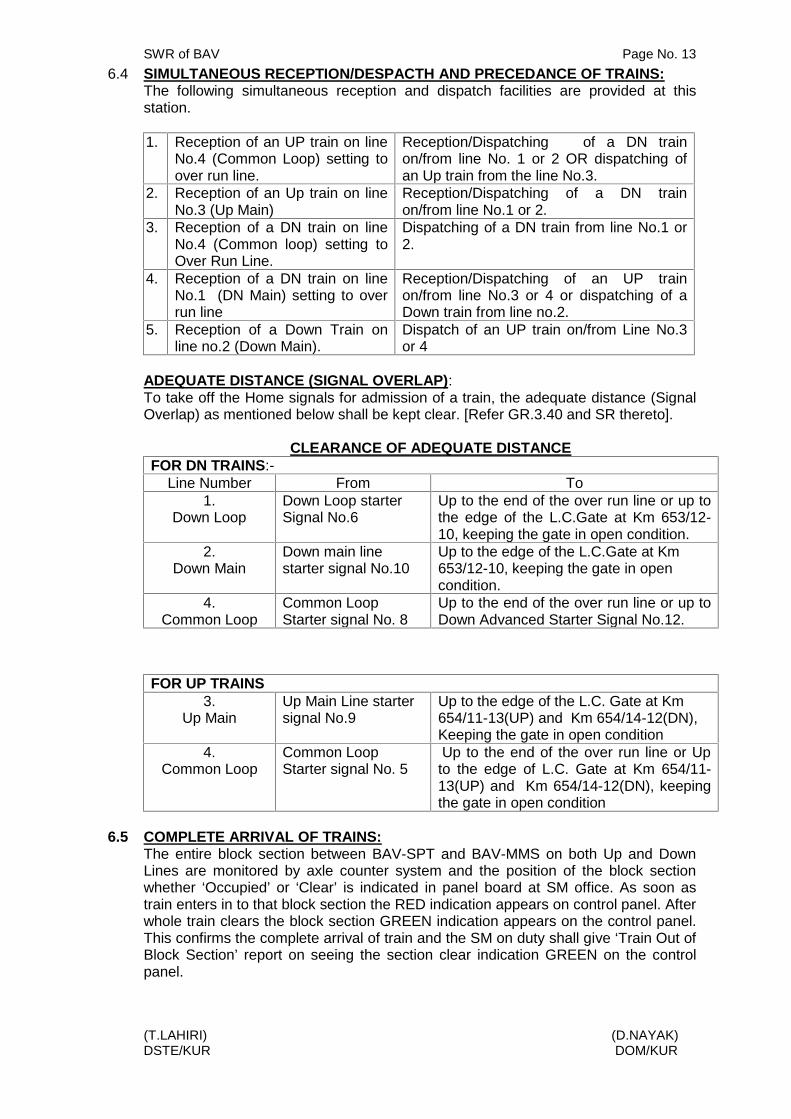
6.4 SIMULTANEOUS RECEPTION/DESPACTH AND PRECEDANCE OF TRAINS:The following simultaneous reception and dispatch facilities are provided at thisstation.
1. Reception of an UP train on lineNo.4 (Common Loop) setting toover run line.
Reception/Dispatching of a DN trainon/from line No. 1 or 2 OR dispatching ofan Up train from the line No.3.
2. Reception of an Up train on lineNo.3 (Up Main)
Reception/Dispatching of a DN trainon/from line No.1 or 2.
3. Reception of a DN train on lineNo.4 (Common loop) setting toOver Run Line.
Dispatching of a DN train from line No.1 or2.
4. Reception of a DN train on lineNo.1 (DN Main) setting to overrun line
Reception/Dispatching of an UP trainon/from line No.3 or 4 or dispatching of aDown train from line no.2.
5. Reception of a Down Train online no.2 (Down Main).
Dispatch of an UP train on/from Line No.3or 4
ADEQUATE DISTANCE (SIGNAL OVERLAP):To take off the Home signals for admission of a train, the adequate distance (SignalOverlap) as mentioned below shall be kept clear. [Refer GR.3.40 and SR thereto].
CLEARANCE OF ADEQUATE DISTANCEFOR DN TRAINS:-
Line Number From To1.
Down LoopDown Loop starterSignal No.6
Up to the end of the over run line or up tothe edge of the L.C.Gate at Km 653/12-10, keeping the gate in open condition.
2.Down Main
Down main linestarter signal No.10
Up to the edge of the L.C.Gate at Km653/12-10, keeping the gate in opencondition.
4.Common Loop
Common LoopStarter signal No. 8
Up to the end of the over run line or up toDown Advanced Starter Signal No.12.
FOR UP TRAINS3.
Up MainUp Main Line startersignal No.9
Up to the edge of the L.C. Gate at Km654/11-13(UP) and Km 654/14-12(DN),Keeping the gate in open condition
4.Common Loop
Common LoopStarter signal No. 5
Up to the end of the over run line or Upto the edge of L.C. Gate at Km 654/11-13(UP) and Km 654/14-12(DN), keepingthe gate in open condition
6.5 COMPLETE ARRIVAL OF TRAINS:The entire block section between BAV-SPT and BAV-MMS on both Up and DownLines are monitored by axle counter system and the position of the block sectionwhether ‘Occupied’ or ‘Clear’ is indicated in panel board at SM office. As soon astrain enters in to that block section the RED indication appears on control panel. Afterwhole train clears the block section GREEN indication appears on the control panel.This confirms the complete arrival of train and the SM on duty shall give ‘Train Out ofBlock Section’ report on seeing the section clear indication GREEN on the controlpanel.

SWR of BAV Page No. 14
(T.LAHIRI) (D.NAYAK)DSTE/KUR DOM/KUR
If a train passes the station without confirming the Last Vehicle Indicator, the SM onduty shall advise the Station in advance to stop the train for last vehicle verificationand he need not to withhold closing of block section in rear for the concerned section.Then he shall obtain confirmation under exchange of Private Number about thecomplete arrival of the train with its last vehicle from the station in advance andsubstance train may be dispatched.
In case of failure of Axle counter the SM on duty shall obtain Complete ArrivalCertificate from the guard of the train in the Complete Arrival Register (T/1410)maintained at the station for stopping train. For through passing train the SM on dutyshall satisfy himself the complete arrival of the train by verification of the Last VehicleIndicator vide SR 4.16.05 that the train arrived complete.
In case a train passes incomplete, action shall be taken as per SR.4.17.02, he “Trainout of Block Section” report shall be withheld to the station in rear until CompleteArrival Certificate is received from the station in advance supported by a privatenumber. Train passing on adjacent line shall be stopped and Guard and Loco Pilotshall be issued with caution Order to proceed cautiously and stop short of anyobstruction as per SR. 4.17.03. On occasions when motor trolley follows a train thepoints shall not be operated until the following motor trolley is admitted on the sameline. In the event of motor trolley is delayed in the section the SM on duty shall takeaction in terms of SR.15.25.03(b)(vi).
6.6 DESPATCH OF TRAINS:To dispatch a train, the Station master on duty having obtained line clear for thattrain, shall set the route for the outgoing train correctly and satisfy himself byobserving the visual indication on the panel board. He shall suspend all non-isolatedshunting and the Station Master will ensure that the Level crossing Gate is closedagainst road traffic and then shall take “OFF” the concerned route starter andadvanced starter signal. The ‘OFF’ aspect of the route starter and advanced starteris the authority to proceed into the block section. [Refer GR 3.38, 3.42, SR3.36.04(b), 3.42.04 and BWM 2.07.5(a)]
The Station Master on duty shall watch the safe passage of the train with its lastvehicle indicator. After the train passes the advanced starter complete, he shall sendthe train entering block section signal to the station in advance. If a train workedwithout Guard or Brake Van the instruction laid down in Subsidiary Rule shall befollowed. The interlocked level crossing gate shall remain closed against road trafficfor dispatch of trains. [ReferSR.4.23.02 & 4.25.02].
NOTEi) Before dispatching a DN train into BAV-SPT block section, the SM on duty shall
ensure the closure of the L.C. gate at 649/13-15 (UP) 649/16-14 (DN) from the gateman on duty supported by a private number.
ii) Before dispatching an UP train into BAV-MMS block section, the SM on duty shallensure the closure of the L.C. gate at 660/9-11 (UP) 660/12-10 (DN) from SM/MMSsupported by a private number
6.7 TRAINS RUNNING THROUGH:The procedure detailed in Para 6.4, 6.5 shall be observed. The Station Master isresponsible to observe/watch the condition of the vehicles on a passing train andshall wave green hand signal horizontally until any thing wrong is noticed on train.For this purpose the Station Master on duty shall stand in such a position that hesees a clear view of the passing train and that his hand signals can clearly be seenby the Loco Pilot and Guard of the train.

SWR of BAV Page No. 15
(T.LAHIRI) (D.NAYAK)DSTE/KUR DOM/KUR
He shall also depute the TPM on duty to the other side, for passing the train. TheTPM on duty shall wave Green hand signal horizontally. He shall show danger handsignal if he notices anything is wrong and reports the same to the SM on duty.
The Station Master on duty is responsible to see that a train passes complete with itslast vehicle indicator. If a train passes without last vehicle indicator or its authorizedsubstitute, action shall be taken as per General and Subsidiary Rule. [Ref GR3.42,4.17 4.42,& SR 4.42.02 (b) (i) ,(ii), (iii),c & (d) ]
6.8 WORKING IN CASE OF FAILURE:PROCEDURE TO BE FOLLOWED FOR WORKING OF TRAINS DURINGFAILURE /SUSPENSION OF INTERLOCKING /SIGNALS/ POINTS:
A. TRACK CIRCUITS:In case of failure of track circuits, the clearance of the concerned line should beensured physically before a train is piloted.
B. AXLE COUNTER:In case of failure of axle counter in the station yard, the clearance of the concernedline should be ensured physically before a train is piloted.
If the axle counter fails between the block section, resetting procedure will beadopted as elaborated in Appendix-B of this SWR. If the axle counter indication doesnot appear ‘Green & continues to show ‘RED’ condition after resetting, the concernedblock section shall be suspended & failure intimation to be given to sectional signalMaintainer /JE/SE (signal ) for rectification.
C. BLOCK INSTRUMENTSIn the event of partial/total failure of block instrument the concerned block instrumentshall be suspended till its rectification and trains shall work as per GR. [Refer SR6.02.03 & 6.02.06)
During this period of time the authority will be T/369(3b) with identification numberand Private Number issued from the station in advance written both in figure andwords.
D RECEPTION OF TRAIN ON OBSTRUCTED LINE:Whenever trains are to be admitted on an blocked line, calling on signal may betaken off. If calling on signals failed then the SM on duty shall authorize on duty TPMwith form T/509, indicating reasons for such admission the line number and nature ofobstruction on that line. Before handing over the authority the SM on duty shallensure the correct setting, clamping, and padlocking of both the facing and trailingend of the concerned route vide SR 3.69.03. A stop hand signal shall be exhibited bySM on duty at a distance of not less than 45M from the point of obstruction toindicate the loco pilot as to where the train shall be brought to stand.
E. RECEIPTION OF A TRAIN ON NON-SIGNALLED LINEBefore receiving a train on non-signalled line, the SM shall ensure that
a. The train is brought to a stand at the first stop signal.b. The line on which it is intended to receive the train is clear up to the trailing points or
up to the place at which the train is required to come to a stand.c. All points over which the train has to pass are correctly set & both, the facing and
trailing points are clamped and padlocked.d. The Loco Pilot is authorized to pass the approach stop signals at ‘ON’ through a
written authority T/369 (3b). [Refer GR 5.10].

SWR of BAV Page No. 16
(T.LAHIRI) (D.NAYAK)DSTE/KUR DOM/KUR
F. DEFECTIVE SIGNALS:When signals become defective, the procedure laid down in GR & SR shall befollowed. A signal in the OFF position is the final indication that the points arecorrectly set for the route for which it applies and if it is found impossible to take OFFa signal, the setting of points on the route to which it applies shall be inspected by theStation Master on duty before the signal is declared as defective irrespective of whatis indicated by the position of the route, [Refer GR 3.68 to 3.71, 3.80 and SR 3.68.01(c)].
In case of disconnection of signal and interlocking for repairs and maintenance,procedure laid down in GR and relevant SRs shall be followed. In the event of signalshowing no lights, Station Master on duty shall before giving line clear initiate actionin accordance with the procedure prescribed in GR and the relevant SRs. [Refer GR3.51, 3.69, 3.49 (4), 3.68 to 3.77]
G. INSPECTION OF POINTS BEFORE DECLARING THEM DEFECTIVE:However, before declaring a signal is defective, the setting of the point on the routeto which it applies shall be inspected by the Station Master irrespective of theposition of the switches point laid down in GR with relevant SRs shall be followed.[Refer GR 3.68, 3.70 & SR 3.77.01(b)]
Initiate action in accordance with the procedure prescribed in GR and relevantSubsidiary Rules there to. [Refer GR 3.49(4) and 3.68, 3.77]
H. DEFECTIVE INTERLOCKINGWhen interlocking becomes defective the SM on duty shall be responsible for correctsetting, clamping and padlocking of points for admission of train. [Refer SR3.69.03(b) (i)].
I. DEFECTIVE/DAMAGED POINTSWhen any point fails to operate normally by the route setting operation throughpanel/VDU it is inevitable to operate the points with crank handle. The SM on dutyshall personally ensure clamping and padlocking of all facing and trailing points onthe route. Crank handles are interlocked with signals and interlocking system. Whenpoints become defective, the signals controlling these points shall be considereddefective and vice-versa and the procedure for use of crank handle. For motoroperated points shall be followed as per operating manual para-20.06.
CRANK HANDLE CONTROL POINTSCH-1 - - - - - - - - - - - - - - - - - - - - - 17CH-2 - - - - - - - - - - - - - - - - - - - - - 18CH-3 - - - - - - - - - - - - - - - - - - - - - 19, 20CH-4 - - - - - - - - - - - - - - - - - - - - - 21, 22
These crank handles are interlocked with the signaling and interlocking system at thisstation and normally locked inside the RKT instrument at the respective CrankHandles Locations. Crank handle keys can be taken out only when all signals are inNormal Position and the route is not locked for whatever reasons. Crank Handle canbe released by pressing common ‘TRANS’ push button and concerned Crank Handlecontrol push button simultaneously. When the keys are taken out no signal can betaken “OFF” over the particular route on the points nominated by that Crank Handle.This key can be electrically transmitted at both locations of the yard for manualoperation of the defective points.

SWR of BAV Page No. 17
(T.LAHIRI) (D.NAYAK)DSTE/KUR DOM/KUR
SM on duty shall personally ensure the clamping and padlocking of all facing andtrailing points. An emergency Crank handle register shall be maintained by the SMon duty at the station as per Para 20.06(d) of the Operating Manual. Correct settingclamping and padlocking of the points devolve on the SM on duty. (Details of use ofCrank Handle as per Appendix-‘B’).
The cases of the motor point should be promptly reported to the concerned signalmaintainer/signal inspector for immediate rectification.
6.9 PROVISIONS FOR WORKING OF TROLLIES/ MOTOR TROLLIES/MATERIALLORRIES ETC”Motor trolleys are to run in accordance with rules laid down in SRs. Material Lorrieswill work in accordance with SR. [Rules laid down in BWM. Refer SR 15.25.03 to15.25.07, 5.11(2), 5.12, 5.13 of BWM]
i) Trolleys, Motor Trolleys ,Lorries which are not insulated ,shall not be allowed to runexcept on Line clear .
ii) Motor Trolleys/Tower Wagon/material Lorries are not likely to actuate the AxleCounter correctly.
iii) In all other respects the Working of a light motor trolley shall conform to the rules laiddown for ordinary trolleys while running without block protection and to those laiddown for motor trolleys while running under block protection or following another lightmotor trolley.
7.0 BLOCKING OF THE LINES:Whenever a running line is blocked either by loose vehicles or by stabling train or by a trainwhich is to cross or give precedence to another train, the points at either end shouldimmediately be set against the blocked line except during shunting movement. Remindercollars shall be placed on the concerned point push button controlling the blocked line. Aclear remark in ‘RED’ ink shall be made immediately in the train signal register and a recordshall be made in the Station Master’s diary also. Stable load register is also to bemaintained. The stable load or loose vehicles are to be secured to prevent rolling down ofvehicles. [Refer SR 3.36.3(b), GR 5.23 and SR 5.23.01]
A. SECURING OF VEHICLES: -As far as practicable. Loose vehicle shall not be allowed to stand on the running line.However under unavoidable circumstances, if it is necessary to detach vehicle from a train orto stable a train and leave them standing on the running line, the SM on duty shall beresponsible to secure the vehicle/stable loads to prevent rolling down of vehicles and arrestobstruction and fouling.
NOTESpecial care should be taken to secure special type vehicles fitted with roller bearingwhile standing in siding or in running lines. [Refer GR 5.23 & SR 5.23.01]
B. USE OF REMINDER BLOCK COLLARS :-Whenever any running line is blocked or when a train is stopped to cross anothertrain or detained for any other reason, even for a short while or during shuntingoperations, the reminder collars shall be used by the SM on duty on the push buttonconcerned. [Refer SR 3.36.03 (b)]
C. ALTERATION OF A POINTS TO A CLEAR LINE WHENEVER A RUNNING LINEIS BLOCKED:
(a) When a running line is blocked by stable load, wagon, vehicles or by a train, which isto cross or to give precedence to another train or immediately after the arrival of atrain at the station etc, the points at either end should immediately be set against theblocked line except when any shunting or any other movement is required to be doneimmediately in that direction on that line.

SWR of BAV Page No. 18
(T.LAHIRI) (D.NAYAK)DSTE/KUR DOM/KUR
(b) If all the lines at a station happen to be blocked, when “Line Clear” has been grantedto a train, the points should be set for the line occupied by a stable load or a goodstrain in that order, so that in case of any mishap, the chances of causalities areminimized. In case all the lines are occupied by passenger carrying trains, pointsshould be set for a loop line to negotiate of which the speed of the incoming trainwould be reduced, which in turn would minimize the consequences/causalities. Whiledoing so, points may be set for a loop occupied by a train, if any, whose engine isfacing the direction of approach of the incoming train rather than for a loop occupiedby a train whose passenger coach will incase, of collision, receive the impact.
D. LOADING AND UNLOADING OF VEHICLES ON RUNNING LINESExcept smalls loading and unloading of vehicles on running line is prohibited unlesspermitted by DOM vide SR 5.19.01.
8. SHUNTING :8.1. GENERAL PRECAUTIONS
Shunting will be carried out at the station in accordance with General Rule andrelevant Subsidiary Rules and Block working Manual. [Refer GR 3.46, 3.52 to 3.56,5.13, 5.14, 5.16, 5.19, 5.20 to 5.23, 8.09, to 8.15]
The Guard/SM on duty is authorised to supervise shunting operation. Normally backshunt signals and caution aspect of starter signals shall be used for shuntingoperations. The official supervising shunting shall ensure the correct setting,clamping and padlocking of points incase of non-signaling movements.
The SM on duty and the official supervising shunting shall co-operate with each otherregarding shunting operations. Neither reception signals nor departure signals shallbe taken ‘OFF’ unless the shunting is isolated and the path of incoming/outgoing trainis free from obstructions. The over-run line may be used as shunting neck.
NOTEFor any signal movement physical verification of the clearance of the cross overpoints shall be ensured by the Guard/SM on duty for supervising shunting operation.
8.2 SHUNTING IN THE FACE OF AN APPROACHING TRAIN :(i) Shunting in the face of an approaching train is prohibited.(ii) No shunting beyond the outermost point should be allowed unless a locomotive is
attached at the lower end of the load from the point of view of gradient.
8.3 PROHIBITION OF SHUNTING (SPECIAL FEATURE IF ANY):Hand/Fly shunting is prohibited at both ends of the yard. Shunting in the face of anapproaching train is prohibited. Shunting is not permitted in the HWH end of the yardunless the engine is leading to wards the falling gradient
8.5 SHUNTING ON DOUBLE LINE-A] SHUNTING OUTSIDE THE STATION SECTIONa) When line clear has been given, no shunting shall be permitted in the Block section
in rear.b) Shunting or obstruction for any other purpose shall not be permitted in the Block
section in rear unless it is clear and is Blocked back.c) Shunting or obstruction for any other purpose shall not be permitted in the Block
section in advance unless it is clear and is blocked forward vide. GR 8.06.(3)

SWR of BAV Page No. 19
(T.LAHIRI) (D.NAYAK)DSTE/KUR DOM/KUR
B] SHUNTING WITHIN STATION SECTIONIf necessary signals are kept at ‘ON’ shunting may be carried on within the stationsection but this shall be done only when there is no approaching train since shuntingin face of an approaching train is prohibited at this station.
8.6 SHUNTING IN THE SIDINGa. GOODS SIDING:
(a) Goods siding at VSKP end of the yard with both side entry is taking off fromCommon Loop (Line No.4). The entrance point and corresponding derailing switchare coupled and operated by an arc lever at site. Both the entrance points are fittedwith hand plunger locks. These hand plunger locks are unlocked by Goods sidingkeys P1 & P2 released by pressing the button No.24 and common group trans buttonprovided on panel/VDU at SM’s office. Reception signals (i.e. 1A. C1A. in Updirection and 2C. C2C. in Down direction) and shunt signal Nos.SH3A, SH4B, andsignal No.5 & 8 are electrically interlocked in such a way that these signals cannot betaken ‘OFF’ if the Goods siding key is taken ‘OUT’ from the RKT provided at Goodssiding location at site.
b) HOT AXLE SIDINGThe hot Axle siding at HWH end of the yard is taken off from line No.1 (DN loop). Theentrance point & corresponding derailing switch are coupled & operated by an arclever at site. The entrance point is fitted with hand plunger locks. The hand plungerlock is unlocked by Hot Axle siding key ‘Q1’. & released by pressing the button No.25 & common group trans button provided on panel/VDU at SM’s office.
Reception signals ( i.e. 2A, C2A in DN direction) & shunt signal No.3D & signal No. 6are electrically interlocked in such a way that these signals can not be taken ‘off’ ifthe Hot Axle siding key is taken ‘OUT’ from the RKT provided at Hot Axle sidinglocation at site.
9.0 ABNORMAL CONDITION: -(i) PARTIAL FAILURE: -
In the event of suspension of Lock and Block Instrument and during partial failure of otheravailable means of communication, the procedures detailed below shall be followed forworking of trains in different situations.
a) Failure/Suspension of Block Instrument or Track Circuit or Axle counters-Line Clear shall be obtained on the Telephone attached to the Block Instrument or stationtelephone exchanged ID number and supported by Private Number.
b) Failure/Suspension of Block Instrument or Track Circuit or Axle Counters or telephoneattached to the Block Instruments or station fixed telephones-‘Line clear’ shall be obtained on Railway auto phone or BSNL phone by exchangingIdentification Number supported by a Private Number.
c) Failure/Suspension of Block Instrument or Track Circuit or Axle counters or telephoneattached to the Block Instruments or station to station fixed telephone or Railway auto phoneor BSNL phone.‘Line Clear’ shall be obtained on control phone by exchanging Identification Numbersupported by a Private Number.
d) Failure/Suspension of Block Instrument or Track Circuit or Axle counters or Telephoneattached to the Block Instruments or Station to station fixed telephone or Railway auto phoneor BSNL phone or control phone.‘Line Clear’ shall be obtained on the VHF sets by exchanging identification Number supportedby a Private Number.
The authority to proceed for the Loco Pilot is T/369(3b) bearing identification Number andPrivate Number received from the station in advance written both in figure and words. [ReferSR 6.02.06 & Chapter –V of BWM]

SWR of BAV Page No. 20
(T.LAHIRI) (D.NAYAK)DSTE/KUR DOM/KUR
ii. THE AUTHORITY TO PROCEED IN OCCUPIED BLOCK SECTION IN CASE OFOBSTRUCTION OF LINE OR ACCIDENT.Rules and regulations for working trains on an obstructed line in case of obstructionor accident on the authority of block ticket (T/A-602) when communications areavailable shall be followed in accordance with the provision which is summarized asfollows. [Refer SR 6.02.05]
After sending a train on Block ticket, a following train shall not be dispatched in thesame direction unless:
i) The previous block ticket is collected & cancelled, orii) Necessary endorsement is given on the previous block ticket with the advise to wait
at the site for a next train to follow, oriii) The previous train has met with an accident or has been disabled, oriv) The block ticket has been collected from the Loco Pilot of the previous train by the
official in-charge at the site & kept in the personal custody & shall be kept until thearrival of the next train & such assurance is given over the telephone installed at thesite quoting the serial number of the Block Ticket so collected.
(a) SM will suspend the absolute block system of working and both SM’s concernedshould arrange for running of trains on the authority of Block Ticket.
(b) SM at the dispatching end will hand over to the Loco Pilot the BLOCK TICKET as theauthority which shall include.
(c) Caution order: Existing speed restriction shall be indicated in the Caution Orderportion. The speed restriction to 15Kmph during clear visibility and 10Kmph whenvisibility is obstructed shall be clearly indicated.
(d) An authority to pass the stop signals at ‘ON’ position.(e) Before resumption of normal working a message between the SM’s of the concerned
station shall be exchanged with private number. [Refer SR 6.02.05(d) (VI)].The block ticket so issued must be collected by SM of either end with a certificateabout the complete arrival of the train with its time and the section is clear of allobstructions from the Loco Pilot/Guard of the train and cancels it.
iii. TRAINS DELAYED IN BLOCK SECTIONSIf a train carrying passenger does not arrive with in 10 minutes OR if a goods traindoes not arrive within 20 minutes after allowing for its normal running time from thestation in rear, the SM at the station in advance shall immediately advise the stationin rear and the control this fact. There after SMs at either end of the Block sectionshall immediately stop all trains proceeding in to the block section on adjacent line ineither direction and warn the Loco Pilots and Guards of such trains by issue ofsuitable Caution Orders. [Refer GR 6.04 & SRs thereto].
iv. Failure of Axle Counter Block/BPAC – Procedure to be followed as detailedv. Procedure for emergency operation of points by Crank Handle.-(a) The detailed Procedure for emergency operation of points by Crank Handle of motor
operated points are given in Para No.6.8. I (Main body).(b) Procedure for emergency operation of points with point zone axle counter/Track
circuits failure and emergency route release.[GR 3.39 and GR 3.77](c ) Certification of clearance of track before Calling –On Signal operation in initiated-
Before taking off Calling –On signal during failure of track circuit/axle counter, theroute and the clearance of the track over which train would pass to be verified by SMon duty.
(d) Reporting of failure of points, Track circuits/axle counter and interlocking-Whenever there is a failure of points, Track circuits/axle counter or any interlockinggear at station , the failure should be reported by SM on duty to the concernedSignaling Maintenance Staff on duty responsible for attending to the failure and onlyafter receipt of the written memo from the Signalling Maintainer for rectification of thefault ,SM should restore the normal working.The entries in failure registers to be done with message to the section controller.
9.1 TOTAL FAILURE OF COMMUNICATION: -
SWR of BAV Page No. 21
(T.LAHIRI) (D.NAYAK)DSTE/KUR DOM/KUR
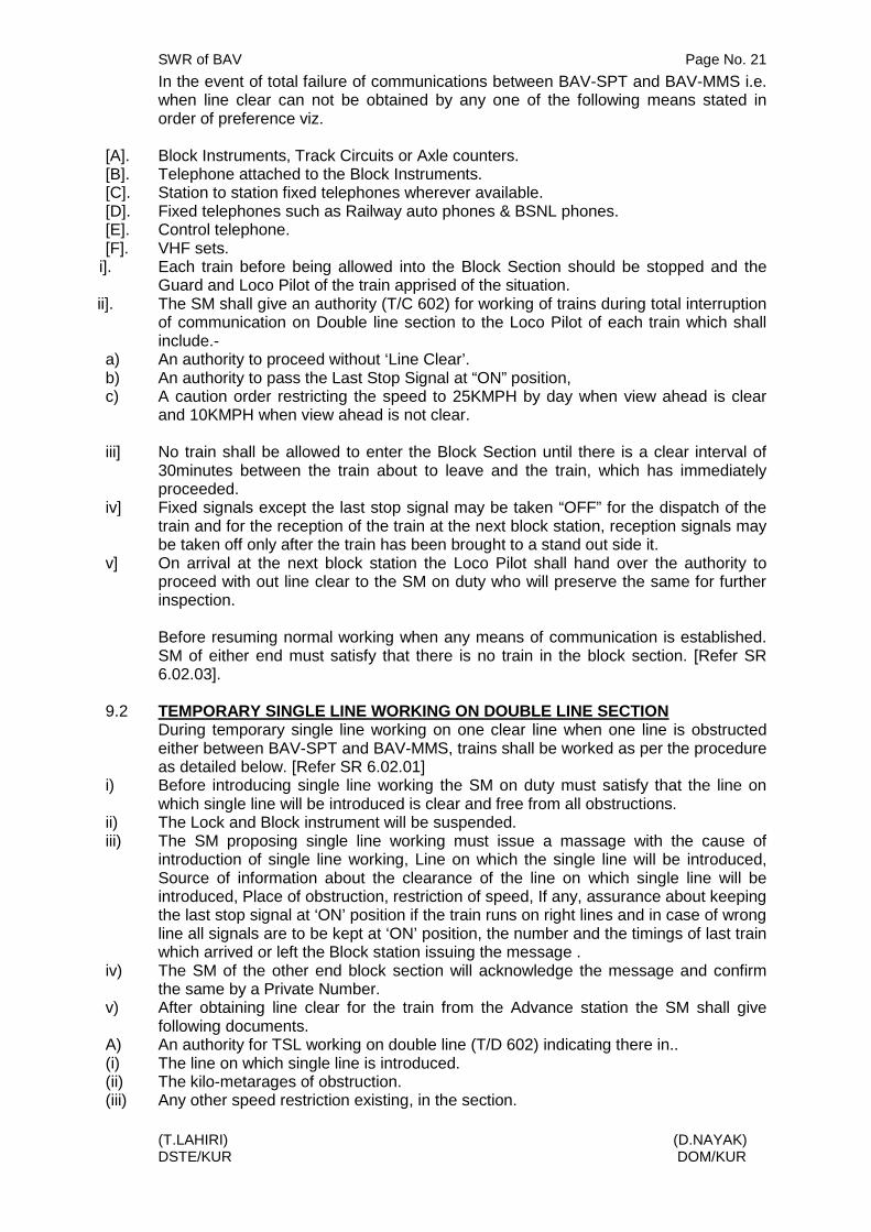
In the event of total failure of communications between BAV-SPT and BAV-MMS i.e.when line clear can not be obtained by any one of the following means stated inorder of preference viz.
[A]. Block Instruments, Track Circuits or Axle counters.[B]. Telephone attached to the Block Instruments.[C]. Station to station fixed telephones wherever available.[D]. Fixed telephones such as Railway auto phones & BSNL phones.[E]. Control telephone.[F]. VHF sets.
i]. Each train before being allowed into the Block Section should be stopped and theGuard and Loco Pilot of the train apprised of the situation.
ii]. The SM shall give an authority (T/C 602) for working of trains during total interruptionof communication on Double line section to the Loco Pilot of each train which shallinclude.-
a) An authority to proceed without ‘Line Clear’.b) An authority to pass the Last Stop Signal at “ON” position,c) A caution order restricting the speed to 25KMPH by day when view ahead is clear
and 10KMPH when view ahead is not clear.
iii] No train shall be allowed to enter the Block Section until there is a clear interval of30minutes between the train about to leave and the train, which has immediatelyproceeded.
iv] Fixed signals except the last stop signal may be taken “OFF” for the dispatch of thetrain and for the reception of the train at the next block station, reception signals maybe taken off only after the train has been brought to a stand out side it.
v] On arrival at the next block station the Loco Pilot shall hand over the authority toproceed with out line clear to the SM on duty who will preserve the same for furtherinspection.
Before resuming normal working when any means of communication is established.SM of either end must satisfy that there is no train in the block section. [Refer SR6.02.03].
9.2 TEMPORARY SINGLE LINE WORKING ON DOUBLE LINE SECTIONDuring temporary single line working on one clear line when one line is obstructedeither between BAV-SPT and BAV-MMS, trains shall be worked as per the procedureas detailed below. [Refer SR 6.02.01]
i) Before introducing single line working the SM on duty must satisfy that the line onwhich single line will be introduced is clear and free from all obstructions.
ii) The Lock and Block instrument will be suspended.iii) The SM proposing single line working must issue a massage with the cause of
introduction of single line working, Line on which the single line will be introduced,Source of information about the clearance of the line on which single line will beintroduced, Place of obstruction, restriction of speed, If any, assurance about keepingthe last stop signal at ‘ON’ position if the train runs on right lines and in case of wrongline all signals are to be kept at ‘ON’ position, the number and the timings of last trainwhich arrived or left the Block station issuing the message .
iv) The SM of the other end block section will acknowledge the message and confirmthe same by a Private Number.
v) After obtaining line clear for the train from the Advance station the SM shall givefollowing documents.
A) An authority for TSL working on double line (T/D 602) indicating there in..(i) The line on which single line is introduced.(ii) The kilo-metarages of obstruction.(iii) Any other speed restriction existing, in the section.

SWR of BAV Page No. 22
(T.LAHIRI) (D.NAYAK)DSTE/KUR DOM/KUR
(iv) Endorsement to inform all Gang man and Gateman about the single line working (forthe first train only).
(v) The speed of the first train to be restricted to 25 KMPH subject to other speedrestriction.
(vi) An authority to pass the last stop signal at its ‘ON’ position. The approach stopsignals at the station in advance may be taken “OFF”. In case a train proceeding onwrong line, the train shall be piloted out and at the receiving station, the train shall bepiloted ‘IN’, on the authority of T/369(3b).
On being ensured that the obstructed line is clear of all obstructions. SM will resumenormal working after exchanging message with the SM of the other concerned endsupported by private number in consultation with the SCR on duty.
A goods train or an engine may be allowed on wrong line by blocking back thesection without introducing single line working. [Refer SR. 6.02.05(g)(i)]
Whenever total interruption of all communication occurs during single line working ondouble line. The procedure detailed in GR should be followed. [Refer SR 6.02.01]
9.3 DESPATCH OF TRAINS UNDER AUTHORITY TO PROCEED WITHOUT LINECLEAR OR TO ASSIST THE CRIPPLED TRAIN:Rules and regulations for working trains on an obstructed line in case of obstructionor accident on the authority of block ticket (T/A-602) when communications areavailable shall be followed in accordance with the provisions which is summarized asfollows. [Refer SR 6.02.05]
After sending a train on Block ticket, a following train shall not be dispatched in thesame direction unless:
i) The previous block ticket is collected & cancelled, orii) Necessary endorsement is given on the previous block ticket with the advice to wait
at the site for a next train to follow ,oriii) The previous train has met with an accident or has been disabled, oriv) The block ticket has been collected from the Loco Pilot of the previous train by the
official in-charge at the site & kept in the personal custody & shall be kept until thearrival of the next train & such assurance is given over the telephone installed at thesite quoting the serial number of the Block Ticket so collected.
a) SM will suspend the absolute block system of working and both SM’s concernedshould arrange for running of trains on the authority of Block Ticket.
b) SM at the dispatching end will hand over to the Loco Pilot the BLOCK TICKET as theauthority which shall include.
c) Caution order: Existing speed restriction shall be indicated in the Caution Orderportion. The speed restriction to 15Kmph during clear visibility and 10Kmph whenvisibility is obstructed shall be clearly indicated.
d) An authority to pass the stop signals at ‘ON’ position.
e) Before resumption of normal working a message between the SM’s of the concernedstation shall be exchanged with private number. [Refer SR 6.02.05(d) (VI)].The block ticket so issued must be collected by SM of either end with a certificateabout the complete arrival of the train with its time and the section is clear of allobstructions from the Loco Pilot/Guard of the train and cancels it.

SWR of BAV Page No. 23
(T.LAHIRI) (D.NAYAK)DSTE/KUR DOM/KUR
10. VISIBILITY TEST OBJECT:The signal lights of common loop starter signal No.5 & 8 during day and night are thevisibility test object vide GR 3.61.2(b)(iii)
11. ESSENTIAL EQUJPIENT AT THE STATION:(Details are given in Appendix-‘E’)
12. FOG SIGNAL MEN NOMINATED TO BE CALLED IN CASE OF FOG.FOG SIGNALLING:-In case of thick, foggy or tempestuous weather impairing visibility, whenever it isnecessary to indicate to the Loco Pilot of an approaching train the locality of a signal,the SM on duty at station shall arrange for signaling in terms of General Rules 3.61and Subsidiary Rules thereto. The assurance of the staff shall be obtained in themonth of OCTOBER every year in the Fog Signal Register vide SR.3.61 as a tokenof their acknowledgement in fog signaling Rules.
Fog signalmen shall be detailed for duty at stations being recruited partly from thestation traffic staff and partly from Engineering Gang man and must not besubstitutes or casual labour but regular employees of the railway.
STATION DETONATOR REGISTER (OPT/124)A Register regarding detonator is maintained at the station.
INSTRUCTIONS:This register contains the following parts.Part. - I: Particulars of fog signal men posted at the station from time to time.
Part – II: Particulars of receipt and stock of detonating (fog) signals at thestation to be filled in whenever detonators are used or received.
Part – III: Periods of fogs, fog signalmen on duty and details of detonators used.
Part – IV: Particulars of issue and testing of fog signals at the station.
b. In charge of the station shall ensure that the information maintained in the register iskept upto date and is accurate in all respects.
c. Transportation inspectors shall check the registers and also the stock of detonatorson hand each time they visit the station and initial with date as an indication havingdone so.

SWR of BAV Page No. 24
(T.LAHIRI) (D.NAYAK)DSTE/KUR DOM/KUR
APPENDICES
APPENDIX-A : WORKING OF LEVEL CROSSING GATES
APPENDIX-B : SYSTEM OF SIGNALLING AND INTERLOCKING ANDCOMMUNICATION ARRANGEMENTS AT THE STATION.
APPENDIX-B1 : STAND BY OPERATION OF SIGNALS, POINTS, L.C.GATES, CRANKHANDLES, SIDING POINTS BY VDU (P.C)
APPENDIX-C : ANTI COLLISION DEVICE ( RAKSHA KAVACH)
APPENDIX-D : DUTIES OF TRAIN PASSING STAFF AND STAFF IN EACHSHIFT
APPENDIX-E : LIST OF ESSENTIAL EQUPMENTS PROVIDED AT THE STATION
APPENDIX-F : RULES OF WORKING OF DK STATION, HALTS, IBH, IBS ANDOUTLYING SIDINGS
APPENDIX-G : RULES FOR WOKING OF TRAINS IN ELECTRIFIED SECTIONS
(T.LAHIRI) (D.NAYAK)DSTE/KUR DOM/KUR

(T.LAHIRI) (P.NAGAR) (D.NAYAK)DSTE/KUR DEN(S)/KUR DOM/KUR
APPENDIX ‘A’ TO STATION WORKING RULES OF BARUVA STATION
1.0 WORKING OF ‘C’ CLASS LEVEL CROSSING BETWEEN STATIONS BARUVA-SOMPETA AT Km. 649/13-15(UP) & 649/16-14 (DN)(L.C.No.348)
1.1 BRIEF DESCRIPTION:1. No. of Level Crossing Gate 3482. Engineering or Traffic gate Engineering.3. Under control of station master or
permanent way inspector.SE/P.Way/SPT
4. Location at Km. 649/13-15(UP) & 649/16-14 (DN)5. At station ---6. In between station BAV-SPT7. BG/MG/NG BG8. Single line/double line/multiple line Double Line9. Normal position Closed10. Interlocked/ Non-Interlocked Non-Interlocked.11. Means of Interlocking ---12. Provision of gate signal at Km. ---13. Signaling arrangement ---14. Means of communication Telephone. Telephone with SS/BAV15. Width of the level crossing gate 4.8m16. Type of road others17. Name of road Buragram.18. Metalled /Non-Metalled Non-Metalled19. Approach road moorum20. Width of the road 7.5m21. Angle of road crossing (in case of the
SKEW gates)---
22. Road gradients (if any) [a]North East Side. Level[b] South West Side. Level
23. Road alignment (straight/Curve) [a] North East Side : straight[b] South West Side : straight
24. Provision of height gauges Yes25. Type of barriers Lifting barrier.26. Length of check rails 9m27. Road surface in between level crossing
gates.---
28. Length of rumble strip/ speed breakers. 4.829. Road signs Yes30. Speed breakers indication board Yes31. TVU 10032 on Nov 200932. Census next due on Nov 201233. Demarcation for placement of detonators. Yes34. No. of gateman working Two35. Nearest Railway Medical Assistance Palasa.36. Nearest Private Medical Assistance
available (if any)SOMPETA
37. List of equipment available (Yes/No) Available.

SWR BAV = A = Page No. 2
(T.LAHIRI) (P.NAGAR) (D.R.PAUL)DSTE/KUR Sr.DEN(S)/KUR DOM/KUR
1.2 EQUIPEMENT TO BE AVAILABLE AT THE GATE:1. Battery Operated LED based flashing lamp 32. Hand Signal Flag Green 1 mounted on sticks3. Hand Signal Flag Red 34. Banner Flag Red 35. Posts for exhibiting red banner flag 26. Spare Chains with Padlocks 2 with stop mark7. Detonators 10 in tin case8. Gate lamps 29. Tommy Bar 110 Mortar Pan 111. Spade/ Fowrah 112. Hammer 113. Pick Axe 114. Tin Case for Flags 115. Cane for oil 116 Water pot/Bucket 117 Canister for Muster roll 118 Set of spare spectacles of gateman wearing glasses 119 Board demarcating protection of level crossing gate
diagram in case of obstruction on gate1
20 Basket 121 Whistle 122 Wall clock 123 Small chain with pad lock 2
1.3 RECORDS TO BE KEPT AT GATE LODGEIn addition to the above equipment, following records shall also be kept at the GateLodge.
i) Gate Working Instructions in Hindi/English.ii) Gate Working, Instructions in local vernacular language.iii) Gateman Rule Book in local vernacular language.iv) List for tools and books.v) Duty Roster.vi) Certificate for working as gateman.vii) Bio-data particulars of Gatemen, including date of passing vision test, initial/refresher
course, safety camp, etc.viii) Accident Register.ix) Record of last census of road traffic at Level Crossing gate.x) Public Complaint Book.xi) Inspection Book.
1.4. NORMAL WORKING OF THE LEVEL CROSSING GATE(NON-INTERLOCKED)The level crossing gate is normally kept closed against road traffic and is opened forpassage of road traffic only when it is necessary and safe to do so. The Gate man onduty shall obtain permission from the Station Master on duty before opening it and shallclose the level crossing gate after passing the road traffic. The Gateman on duty shall bealert entirely depending on the information of the Station Master to open the levelcrossing for the passage of road traffic.

SWR BAV = A = Page No. 3
(T.LAHIRI) (P.NAGAR) (D.R.PAUL)DSTE/KUR Sr.DEN(S)/KUR DOM/KUR
1.5 DUTIES OF GATEMAN:(1) ALERTNESS: The gateman shall be alert and be prepared to take immediate action,
should danger be apprehended. Keys of the gate shall be in his personal custody.
(2) POSITION DURING PASSAGE OF TRAINS:During passage of trains, gateman will stand in the manner indicated below:
(i) Gateman will stand attentively in front of the gate lodge facing the approaching train.(ii) In day time, gateman shall hold red and green flags furled up on separate sticks in right
and left hands respectively.(iii) In night time, gateman shall hold lighted hand signal lamp with white light facing the
track.(iv) He shall keep the whistle slung around his neck from a cord.
(3) ROUTINE DUTIES OF GATEMAN:(i) Gateman shall ensure that red banner flag is placed across the track whenever the gate
is kept in open condition for passage of road vehicles.(ii) Gateman shall ensure that gate lamps and lamps of all gate signals are lighted and kept
burning continuously from sunset to sunrise.(iii) Gateman shall perform his duties strictly according to the duty roster and shall not leave
the gate unless reliever arrives and takes charge of it. However, if it is necessary toleave the gate in an emergency, he must close and lock the gates against road traffic,before leaving the gate.
(iv) Except where otherwise prescribed under special instructions, he shall observe allpassing trains and be prepared to take such action as may be necessary to ensuresafety of trains.
(v) Gateman shall watch all passing trains and keep sharp look out for any unusual like hotaxle, hanging chains, hanging battery, any vehicle / wagons / train / battery box on fire,shifted load, falling material like brake blocks, brake beams, safety bracket, vaccumcylinder or any other situation endangering safe running of trains.
(vi) Gateman shall also be prepared to repeat any signal which guard may give to Loco Piloton walkie – talkie or in any other way.
(vii) If lifting barriers / leaf gates get damaged or becomes out of order, the gateman shalluse the spare chain with disc and padlocks for securing the gate against road traffic.
(viii) Gateman shall report to the nearest SM, Gangmate or Permanent Way Inspector anydefect in his gate or apparatus pertaining to it, as soon as possible.
(ix) In the event of gate signal becoming defective the gateman shall maintain the signal inthe ‘ON’ position even by disconnecting the signal or the wire if necessary.
(x) At the gate whose signal have become defective, the gateman shall close and lock andlifting barriers / leaf gates on sighting a train and hand signal or pilot the train past thedefective signal. In such case he should inform the Loco Pilot to report the defect at thenext station.
(xi) Gateman shall wear badge and prescribed uniform while on duty at level crossing gate.(xii) Gateman shall ensure that he is having competency certificate in his possession while
on duty.(xiii) Gateman shall work the gate as per Gate Working Instructions and remain well
conversant with these instructions.(xiv) Gateman shall ensure that equipment supplied at the gate is in good order and ready for
immediate use.(xv) Gateman shall see that the channel for the flange of the wheel is kept clear.

SWR BAV = A = Page No. 4
(T.LAHIRI) (P.NAGAR) (D.R.PAUL)DSTE/KUR Sr.DEN(S)/KUR DOM/KUR
(xvi) Gateman shall keep the road surface well watered and rammed in case of unmetalledroads.
(xvii) Gateman must be vigilant to see that inconvenience to road users due to closure ofgates should be to the minimum possible extent.
(xviii) Gateman on electrified section shall watch that road vehicles / animals passing fromgate are within the height loading gauge provided on either side of the level crossinggate.
(xix) Gateman shall prevent trespassing by persons or cattle to the maximum extent.
(4) ACTION IN CASE OF UNUSUAL OCCURRENCE ON TRAIN :In case gateman observes anything unusual with a passing train, he shall take followingaction.
(i) He shall take prompt action to warn the Loco Pilot / guard of the passing train byshowing red flag by day and red light by night.
(ii) He shall simultaneously try to draw the attention of the Loco Pilot / guard by whistlingcontinuously, shouting, gesticulating, throwing ballast on the brake van or by any othermeans.
(iii) If Loco Pilot/guard fails to take notice, gateman shall immediately inform the StationMaster,if connected on telephone, to take appropriate action, under exchange of privatenumber.
(iv) In case of train parting, gateman shall not show stop hand signal but shall showprescribed signal for train parting.
(v) He shall endeavor to attract the attention of the Loco Pilot/guard by whistlingcontinuously, shouting, gesticulating and by raising both hands vertically above, quicklyparting them and bringing them together in repeated Up and Down motion as high andas low as possible.
(vi) In case the train does not stop, gateman shall immediately inform the Station Master, ifconnected on telephone, to take appropriate action, under exchange of private number.
(5) ACTION IN AN EMERGENCY AT THE LEVEL CROSSING:i) In case of an obstruction at the level crossing gate, gateman shall maintain the gate
signals, if any, in the ‘ON’ position.ii) Thereafter, if he is unable to remove the obstruction, gateman shall immediately advise
the Station Master on duty, if connecting by telephone, regarding thedefects/obstructions at the gate, under exchange of private number.
iii) If there is no response from the Station Master after two or three attempts, he shall firstprotect the gate and then inform on phone.
The gateman shall protect the line as under:-(a) ON DOUBLE LINE SECTION:i) If both lines are obstructed the gateman shall plant a red banner flag by day and a red
light by night 5 meters away on posts duly provided for the purpose. He shall firstprotect the line on which a train is expected to arrive first.
ii) The he will similarly plant the other red banner flag by day and red light by night on theother line 5 meters away from the site of obstruction.
iii) Gateman shall then proceed to protect the gate along with detonators, Battery operatedLED based flashing lamps and red flag by day and red hand signal lamp by night.
iv) Gateman shall proceed exhibiting red flag by day and red hand signal lamp by night onthe line on which a train is excepted to arrive first, to a point 600 meters on BG andplace one detonator on the line. Thereafter he shall proceed to a distance 1200 on BGfrom the level crossing gate and place 3 detonators on the track 10 meters apart. Having

SWR BAV = A = Page No. 5
(T.LAHIRI) (P.NAGAR) (D.R.PAUL)DSTE/KUR Sr.DEN(S)/KUR DOM/KUR
thus protected the line he shall return to the level crossing gate picking up theintermediate detonator on his way back.
v) Thereafter, he shall proceed on the other line, showing red hand signal, similarly placedetonators as described in para (iv) above and return to the site of obstruction, pickingup the intermediate detonator on his way back.
vi) Having returned to the gate, he must then take steps to remove the obstruction and warnthe Loco Pilot of the approaching train.
vii) In case the gateman observes or hears a train approaching when he is still on his way toprotect and before he reaches the stipulated distance to place detonators, he shall placedetonators on the line at a distance as far away as he can go.
viii) Thereafter, he shall light up and fix the Battery operated LED based flashing lamp towarn the Loco Pilot and stop the approaching train by waving his red flag by day redhand signal lamp by night repeatedly.
(b) OTHER ACTION TO BE TAKEN BY GATEMAN:i) At night gateman shall light two hand signal lamps and take action to exhibit red light
and protect the lines as described in sub paras (a) and (b) above.ii) If the gate is broken by a road vehicle which is fouling the track, or if lifting barriers / leaf
gates or any other part of the gate foul the track, or if there is any other obstruction at thegate, the gateman shall take immediate action.
iii) He shall note down the particulars of the road vehicle, vehicle number, name of the LocoPilot, owner and relay these details to the nearest Station Master or Permanent WayInspector regarding the particulars and obstructions at the level crossing gate, throughmessenger or other means available.
1.6 EXCHANGE OF PRIVATE NUMBER:(i) Gateman must seek permission from station master for opening of the gate.(ii) If the gate is required to be opened to pass the road traffic, the gateman shall exchange
private number with the SM, and confirm that the train has passed completely from hisgate, there after the SM may allow the gate man to open the gate. In such a situation theSM before dispatching or giving line clear for any other train in the Block Section inquestion shall ensure that the level crossing gate is closed for road traffic and assuranceof the gate man is taken through exchange of private number. In addition, the gatemanbefore opening the gate shall do so only if the SM has not advised the gateman to keepthe gate closed for any other train from the same direction or from the other directionunder exchange of Private Number.
(iii) Suitable entries shall be made by the station master in the TSR & Private no book in redink.
(iv) After passage of road traffic, the gateman shall close the gate and confirm this to StationMaster under exchange of private number.
(v) Before any train is allowed to enter the block section again, the Station Master mustensure that private number from gateman has been received in token of his havingclosed the gate.
(vi) Gate once closed for the road traffic must on no account be opened unless this isauthorized by the Station Master, under exchange of private number.
1.7 FAILURE OF TELEPHONIC COMMUNICATIONWhen telephonic communication fails or it does not get any response from gatemandespite 2 or 3 attempts, the following procedure should be adopted:

SWR BAV = A = Page No. 6
(T.LAHIRI) (P.NAGAR) (D.R.PAUL)DSTE/KUR Sr.DEN(S)/KUR DOM/KUR
(i) Station Master at dispatching end shall issue caution order to the Loco Pilot of thedeparting train.
(ii) The caution order shall advice the Loco Pilot to whistle continuously and approach thegate cautiously.
(iii) The Loco Pilot shall be instructed to pass the gate cautiously, on being hand signaled bythe gate man. If hand signal is not seen, the Loco Pilot should prepare to stop short ofthe gate and depute his assistant Loco Pilot to see the condition of the gate. If gate isclosed, the assistant Loco Pilot will give all right signal and if the gate is not closed theassistant Loco Pilot must close the gate and then give all right signal. In the absence ofthe assistant Loco Pilot, the Loco Pilot may take the assistance of assistant guard/guard.
(iv) In case of an approaching train, the station master shall advise the station master at thedispatching end, under exchange of private number that the telephone at the gate hasfailed.
(v) The Station Master at the dispatching end shall then issue a caution order to the LocoPilot before dispatching a train in the block section from his end.
(vi) The Station Master shall advise the gateman through gangman/patrol man or the LocoPilot of the first train that the telephone has become defective.
(vii) He should also advise S&T staff responsible for maintenance of the telephone to rectifythe same at the earliest.
(viii) Normal working will be resumed only after S&T staff rectifies the telephone and issuereconnection/fit memo for the same.
1.8 FAILURE OF LIFTING BARRIERS OR LEAF GATES:(i) When the gate cannot be closed due to failure of lifting barriers or leaf gates, the
gateman will immediately inform the Station Master on duty, under exchange of privatenumber, and ensure that lifting barriers or leaf gates do not foul the track.
(ii) He shall immediately fix red banner flag by day and red light by night on the post at thatend first from which the train is approaching and then at the other end.
(iii) Gateman shall secure the gate against road traffic by means of safety chains andpadlocks.
(iv) After securing the gate against road traffic, gateman shall show green hand signal flagby day and green light at night to the Loco Pilot of the approaching train.
(v) Station Master on duty shall issue caution order to the Loco Pilot of departing train.(vi) He shall also advise the Station Master at the dispatching end, under exchange of
private number, to similarly issue a caution order to the Loco Pilot before dispatching atrain in the block section from his end.
(vii) Station Master shall advise maintenance staff responsible for maintenance of liftingbarriers/ leaf gates to rectify the defect at the earliest.
(viii) Normal working will resumed only after maintenance staff rectify the lifting barrier/ leafgates and issue reconnection/ fit memo for the same.
1.9 OBSTRUCTION AT THE GATE:(i) If the gate is broken by a road vehicle which is fouling the track or if lifting barriers/ leaf
gates or any other part of the gate foul the track, or if there is any other obstruction at thegate, the gateman shall immediately fix red banner flag by day and red lamp by night onposts provided at both ends of the gate, for this purpose.
(ii) Immediately after this, the gateman shall advise the Station Master on duty, regardingthe defects / obstructions at the gate, under exchange of private number.
(iii) Station Master on duty shall be advised to put the reception/departure signals back to‘ON’ position, if taken ‘OFF’ for a train.

SWR BAV = A = Page No. 7
(T.LAHIRI) (P.NAGAR) (D.R.PAUL)DSTE/KUR Sr.DEN(S)/KUR DOM/KUR
(iv) If there is no response from the Station Master after two or three attempts, he shall firstprotect the gate and then inform on phone.
(v) Gateman shall then rush with detonators, Battery operated LED based flashing lamp,and red flag by day and red hand signal lamp by night in the direction of the approachingtrain and protect the gate vide GR.16.07.
(vi) Thereafter he shall protect the gate from the other direction also.(vii) He shall note down the particulars of the road vehicle, name of the Loco Pilot, owner and
relay these details to the Station Master who shall not start the train unless he has beenensured by the gateman that the road vehicle or the lifting barriers/ leaf gates are notfouling the track.
(viii) The Station Master shall also inform the Station Master at the dispatching end, underexchange of private number, asking him not to dispatch any train in the block sectionfrom his end, until the track has been cleared of all obstruction.
(ix) After the track has been cleared of all obstructions the gateman shall inform the StationMaster accordingly, under exchange of private number.
(x) Station Master shall then issue a caution order to Loco Pilots of all trains to proceedcautiously, and pass the gate on green hand signal of the gateman, if the gate is broken,but clear of any obstruction.
(xi) Gateman shall secure the gate against road traffic by means of safety chains andpadlocks and there after exhibit green hand signal, if the gate is not obstructed.
(xii) Station Master shall advise maintenance staff responsible for maintaining the liftingbarriers/leaf gate to repair the same at the earliest.
(xiii) Normal working will be resumed only after maintenance staff rectify the defective liftingbarriers/ leaf gates and issue reconnection/ fit memo for the same.
1.10 OBSTRUCTION ON THE TRACK NEAR LEVEL CROSSING GATE:If there is a rail fracture or obstruction on the track due to falling of a tree, fouling by roadvehicle or derailment which is visible to the gateman, the gateman and Station Masterwill adopt the procedure given under item No.1.9 above. If the obstruction fouls the LevelCrossing Gate, gate man must keep the gates closed against road traffic till the track iscleared of the obstruction.

SWR BAV = A = Page No. 8
(T.LAHIRI) (P.NAGAR) (D.R.PAUL)DSTE/KUR Sr.DEN(S)/KUR DOM/KUR
2.0 WORKING OF ‘Spl’ CLASS LEVEL CROSSING AT BARUVA STATION AT KM.653/9-11(UP) & 653/12-10(DN), (L.C.No.351).
2.1 BRIEF DESCRIPTION:1 No. of Level Crossing Gate 3512 Engineering or Traffic gate Traffic3 Under control of station master or permanent
way inspector.SM/BAV
4 Location at Km. 653/9-11(UP) & 653/12-10(DN)5 At station ---6 In between station SPT-BAV7 BG/MG/NG BG8 Single line/double line/multiple line Double line9 Normal position Open10 Interlocked/ Non-Interlocked Interlocked11 Means of Interlocking EKT12 Provision of gate signal at Km. ---13 Signaling arrangement Station Stop Signal14 Means of communication Telephone. Telephone with SM/BAV15 Width of the level crossing gate 5.5m16 Type of road Other17 Name of road Baruva18 Metalled /Non-Metalled Metalled.19 Approach road Black Top20 Width of the road 5.5m21 Angle of road crossing
(in case of the SKEW gates)---
22 Road gradients (if any) [a]North East Side. Level[b] South West Side. Level
23 Road alignment (straight/Curve) [a] North East Side Straight[b] South West Side Straight
24 Provision of height gauges Yes25 Type of barriers Lifting26 Length of check rails 7.30m27 Road surface in between level crossing gates. Black Top28 Length of rumble strip/ speed breakers. 5.5m29 Road signs Yes30 Speed breakers indication board Yes31 TVU 34839 Nov 200932 Census next due on Nov 201233 Demarcation for placement of detonators. Available34 No. of gateman working 03 (Three)35 Nearest Railway Medical Assistance Palasa.36 Nearest Private Medical Assistance available (if
any)Baruva.
37 List of equipment available (Yes/No) Yes

SWR BAV = A = Page No. 9
(T.LAHIRI) (P.NAGAR) (D.R.PAUL)DSTE/KUR Sr.DEN(S)/KUR DOM/KUR
2.2.A. EQUIPEMENT TO BE AVAILABLE AT THE GATE :
1. Battery Operated LED based flashing lamp 32. Hand Signal Flag Green 1 mounted on sticks3. Hand Signal Flag Red 34. Banner Flag Red 35. Posts for exhibiting red banner flag 26. Spare Chains with Padlocks 2 with stop mark7. Detonators 10 in tin case8. Gate lamps 29. Tommy Bar 110 Mortar Pan 111. Spade/ Fowrah 112. Pick Axe 113. Tin Case for Flags 114. Cane for oil 115. Water pot/Bucket 116. Canister for Muster roll 117. Set of spare spectacles of gateman wearing glasses 118. Board demarcating protection of level crossing gate
diagram in case of obstruction on gate1
19. Basket 120. Whistle 121. Wall clock 122. Small chain with padlock 2
B. RECORDS TO BE KEPT AT GATE LODGEIn addition to the above equipment, following records shall also be kept at the Gate Loge.
1. Gate Working Instructions in Hindi/English.2. Gate Working, Instructions in local vernacular language.3. Gateman Rule Book in local vernacular language.4. List for tools and books.5. Duty Roster.6. Certificate for working as gateman.7. Bio-data particulars of Gatemen, including date of passing vision test, initial/refresher
course, safety camp, etc.8. Accident Register.9. Record of last census of road traffic at Level Crossing gate.10. Public Complaint Book.11. Inspection Book.
2.3. INTERLOCKING AND NORMAL WORKING:This gate is interlocked with all UP reception signals and DN dispatch signals. Theinterlocking is achieved by means of Electrical Key Transmission System. The normalposition of the gate is open. A two-lever ground frame is provided at the gate lodge.The key of the L.C.Gate remains in the winch when the gate is opened. When it isnecessary to close the gate for taking off signals or for shunting operation the StationMaster on duty shall inform the Gateman to close and lock the gate.

SWR BAV = A = Page No. 10
(T.LAHIRI) (P.NAGAR) (D.R.PAUL)DSTE/KUR Sr.DEN(S)/KUR DOM/KUR
The Gateman on duty shall then close the barriers of the L.C.Gate by operating winch.The key ‘M’ is to be extracted from the winch, which will be inserted in the lever of GF-2.When GF-2 reversed locks the booms of the gates and Key ‘N’ and GF-1’ releases. Thiskey ‘N’ will be inserted in the EKT and turned and lever No.1GF will be reversed fortaking “OFF” UP Home/Calling-on Signals (1A/B, C-1A/B), DN Starter Signal No.6,8,10and shunt signal no SH-3A/B/C/D. Station Master on duty will press level crossingcontrol button No.23 (Chocolate) and group button (release), L.C.Gate closed indicationwill appear in the panel and concerned signals automatically get released.
After the passage of train or completion of shunting the Station Master on duty shallinform the Gateman and press L.C.Gate controlling button No.23 and Common groupbutton (Trans) and keep it pressed till such time the Gateman extracts the gate controlkey ‘N’ from the EKT instrument. After getting the Key ‘M’ the Gateman will open theL.C.Gate by normalising the levers.
Emergency gate release operation facility is provided in the panel when the route getslocked due to some failure. For emergency release of gate, the SM on duty shall presssignal cancellation button and then emergency gate release button and gate buttonNo.23. A red flashing (Gate lock) indication will appear and after a lapse of 120sec. Gatelock indication will disappear and a white light will glow over the emergency gate releasebutton indicating that the operation is matured. The SM on duty shall then operate pushbutton for gate 23 and group Trans button to release the key from EKT in gate Lodge.All such operation will be registered in the emergency gate operation counter. All suchemergency operation shall be recorded in the station diary and in the register meant forit.
Lever No 1 is provided at the gate lodge to put back the any concerned signal to dangerin case of emergency by pulling the lever No 1 to normal position.
2.4. DUTIES OF GATEMAN:(1) ALERTNESS: The gateman shall be alert and be prepared to take immediate action,
should danger be apprehended. Keys of the gate shall be in his personal custody.
(2) POSITION DURING PASSAGE OF TRAINS:During passage of trains, gateman will stand in the manner indicated below:
(i) Gateman will stand attentively in front of the gate lodge facing the approaching train.(ii) In day time, gateman shall hold red and green flags furled up on separate sticks in right
and left hands respectively.(iii) In night time, gateman shall hold lighted hand signal lamp with white light facing the
track.(iv) He shall keep the whistle slung around his neck from a cord.
(3) ROUTINE DUTIES OF GATEMAN:(i) Gateman shall place red banner flag during emergencies and obstruction on the track.(ii) Gateman shall ensure that gate lamps and lamps of all gate signals are lighted and kept
burning continuously from sunset to sunrise.(iii) Gateman shall perform his duties strictly according to the duty roster and shall not leave
the gate unless reliever arrives and takes charge of it. However, if it is necessary toleave the gate in an emergency, he must close and lock the gates against road traffic,before leaving the gate.

SWR BAV = A = Page No. 11
(T.LAHIRI) (P.NAGAR) (D.R.PAUL)DSTE/KUR Sr.DEN(S)/KUR DOM/KUR
(iv) Except where otherwise prescribed under special instructions, he shall observe allpassing trains and be prepared to take such action as may be necessary to ensuresafety of trains.
(v) Gateman shall watch all passing trains and keep sharp look out for any unusual like hotaxle, hanging chains, hanging battery, any vehicle / wagons / train / battery box on fire,shifted load, falling material like brake blocks, brake beams, safety bracket, vacuumcylinder or any other situation endangering safe running of trains.
(vi) Gateman shall also be prepared to repeat any signal which guard may give to Loco Piloton walkie – talkie or in any other way.
(vii) If lifting barriers / leaf gates get damaged or becomes out of order, the gateman shalluse the spare chain with disc and padlocks for securing the gate against road traffic.
(viii) Gateman shall report to the nearest SM, Gangmate or Permanent Way Inspector anydefect in his gate or apparatus pertaining to it, as soon as possible.
(ix) In the event of gate signal becoming defective the gateman shall maintain the signal inthe ‘ON’ position even by disconnecting the signal or the wire if necessary.
(x) At the gate whose signal have become defective, the gateman shall close and lock andlifting barriers / leaf gates on sighting a train and hand signal or pilot the train past thedefective signal. In such case he should inform the Loco Pilot to report the defect at thenext station.
(xi) Gateman shall wear badge and prescribed uniform while on duty at level crossing gate.(xii) Gateman shall ensure that he is having competency certificate in his possession while
on duty.(xiii) Gateman shall work the gate as per Gate Working Instructions and remain well
conversant with these instructions.(xiv) Gateman shall ensure that equipment supplied at the gate is in good order and ready for
immediate use.(xv) Gateman shall see that the channel for the flange of the wheel is kept clear.(xvi) Gateman shall keep the road surface well watered and rammed in case of unmetalled
roads.(xvii) Gateman must be vigilant to see that inconvenience to road users due to closure of
gates should be to the minimum possible extent.(xviii) Gateman on electrified section shall watch that road vehicles / animals passing from
gate are within the height loading gauge provided on either side of the level crossinggate.
(xix) Gateman shall prevent trespassing by persons or cattle to the maximum extent.
(4) ACTION IN CASE OF UNUSUAL OCCURRENCE ON TRAIN :In case gateman observes anything unusual with a passing train, he shall take followingaction.
(i) He shall take prompt action to warn the Loco Pilot / guard of the passing train byshowing red flag by day and red light by night.
(ii) He shall simultaneously try to draw the attention of the Loco Pilot / guard by whistlingcontinuously, shouting, gesticulating, throwing ballast on the brake van or by any othermeans.
(iii) If Loco Pilot/guard fails to take notice, gateman shall immediately inform the StationMaster, to take appropriate action, under exchange of private number.
(iv) In case of train parting, gateman shall not show stop hand signal but shall showprescribed signal for train parting.
(v) He shall endeavor to attract the attention of the Loco Pilot/guard by whistlingcontinuously, shouting, gesticulating and by raising both hands vertically above, quickly

SWR BAV = A = Page No. 12
(T.LAHIRI) (P.NAGAR) (D.R.PAUL)DSTE/KUR Sr.DEN(S)/KUR DOM/KUR
parting them and bringing them together in repeated Up and Down motion as high andas low as possible.
(vi) In case the train does not stop, gateman shall immediately inform the Station Master, ifconnected on telephone, to take appropriate action, under exchange of private number.
(5) ACTION IN AN EMERGENCY AT THE LEVEL CROSSING:(i) In case of an obstruction at the level crossing gate, gateman shall maintain the gate
signals, in the ‘ON’ position.(ii) Thereafter, if he is unable to remove the obstruction, gateman shall immediately advise
the Station Master on duty, regarding the defects/obstructions at the gate, underexchange of private number.
(iii) If there is no response from the Station Master after two or three attempts, he shall firstprotect the gate and then inform on phone.The gateman shall protect the line as under:-
(a) ON DOUBLE LINE SECTION:(i) If both lines are obstructed the gateman shall plant a red banner flag by day and a red
light by night 5 meters away on posts duly provided for the purpose. He shall firstprotect the line on which a train is expected to arrive first.
(ii) The he will similarly plant the other red banner flag by day and red light by night on theother line 5 meters away from the site of obstruction.
(iii) Gateman shall then proceed to protect the gate along with detonators, Battery operatedLED based flashing lamps and red flag by day and red hand signal lamp by night.
(iv) Gateman shall proceed exhibiting red flag by day and red hand signal lamp by night onthe line on which a train is excepted to arrive first, to a point 600 meters on BG andplace one detonator on the line. Thereafter he shall proceed to a distance 1200 on BGfrom the level crossing gate and place 3 detonators on the track 10 meters apart. Havingthus protected the line he shall return to the level crossing gate picking up theintermediate detonator on his way back.
(v) Thereafter, he shall proceed on the other line, showing red hand signal, similarly placedetonators as described in para (iv) above and return to the site of obstruction, pickingup the intermediate detonator on his way back.
(vi) Having returned to the gate, he must then take steps to remove the obstruction and warnthe Loco Pilot of the approaching train.
(vii) In case the gateman observes or hears a train approaching when he is still on his way toprotect and before he reaches the stipulated distance to place detonators, he shall placedetonators on the line at a distance as far away as he can go.
(viii) Thereafter, he shall light up and fix the Battery operated LED based flashing lamp towarn the Loco Pilot and stop the approaching train by waving his red flag by day redhand signal lamp by night repeatedly.
(b) OTHER ACTION TO BE TAKEN BY GATEMAN:(i) At night gateman shall light two hand signal lamps and take action to exhibit red light
and protect the lines as described in sub paras (a) above.(ii) If the gate is broken by a road vehicle which is fouling the track, or if lifting barriers or
any other part of the gate foul the track, or if there is any other obstruction at the gate,the gateman shall take immediate action.
(iii) He shall note down the particulars of the road vehicle, vehicle number, name of the LocoPilot, owner and relay these details to the nearest Station Master or Permanent WayInspector regarding the particulars and obstructions at the level crossing gate, throughmessenger or other means available.

SWR BAV = A = Page No. 13
(T.LAHIRI) (P.NAGAR) (D.R.PAUL)DSTE/KUR Sr.DEN(S)/KUR DOM/KUR
2.5 INTIMATION TO GATEMANi) Before taking off reception/departure/shunt signals, Station Master shall inform the
gateman , the number, description and direction of the train.ii) The gateman shall close the gate and transfer the key to the station master.iii) The reception/departure /shunt signals will be taken “OFF”.iv) In order to ensure that road traffic is not held up for a long time, the station master must
ensure that the train is ready for arrival/departure/shunting in all respects before headvises the gateman for closing the gate.
v) When a train has to be piloted to and from the station yard or any shunting movement isto be done, the staff deputed to pilot the trains or to perform the shunting across the gateshall be personally responsible to ensure that the gate is closed against road trafficbefore allowing any movement across the gate.
2.6 FAILURE OF TELEPHONE COMMUNICATION:When Telephonic Communication fails or it does not get any response from theGateman despite 2 or 3 attempts, the following procedure should be adopted:
I) Station Master on duty shall send written advice to the gateman through the porter withfull details of number, description and direction of the train.
II) Gateman on receipt of such advice shall close the gate and transmit the key to theStation Master which will enable them to take “OFF” reception/ departure signals.
III) When sufficient time is not available because of greater frequency of train service,Station Master will issue written authority to the train Loco Pilot to pass the signal at“ON” position.
IV) In addition Station Master shall also issue a caution order advising the Loco Pilot towhistle continuously and approach the gate cautiously.
V) The train Loco Pilot shall be instructed to pass the gate cautiously, on being handsignaled by the gateman. If hand signal is not seen, Loco Pilot should be prepared tostop short of the gate and ensure that gate is closed following GR 3.73 (2) (b).
VI) In case of an approaching train, the Station Master shall advise the Station Master at thedispatching end, under exchange of private number that the telephone at the gate hasfailed.
VII) The Station Master at the dispatching end shall then issue a caution order to the LocoPilot before dispatching a train in the block section from his end.
VIII) He should also advise S & T staff responsible for maintenance of the telephone to rectifythe defect at the earliest.
IX) Normal working will be resumed only after S & T staff rectify the telephone and issuereconnection/ fit memo for the same.
2.7 FAILURE OF LIFTING BARRIERS(i) When the gate cannot be closed due to failure of lifting barriers , the gateman will
immediately inform the Station Master on duty, under exchange of private number, andensure the lifting barriers or leaf gates do not foul the track.
(ii) He shall immediately fix red banner flag by day and red light by night on the post at thatend first from which the train is approaching and then at the other end.
(iii) Gateman shall secure the gate against road traffic by means of safety chains andpadlocks.
(iv) After securing the gate against road traffic, gateman shall show green hand signal flagby day and green light to the Loco Pilot of the approaching train.
(v) Station Master on duty shall issue caution order to the Loco Pilot of departing trains.
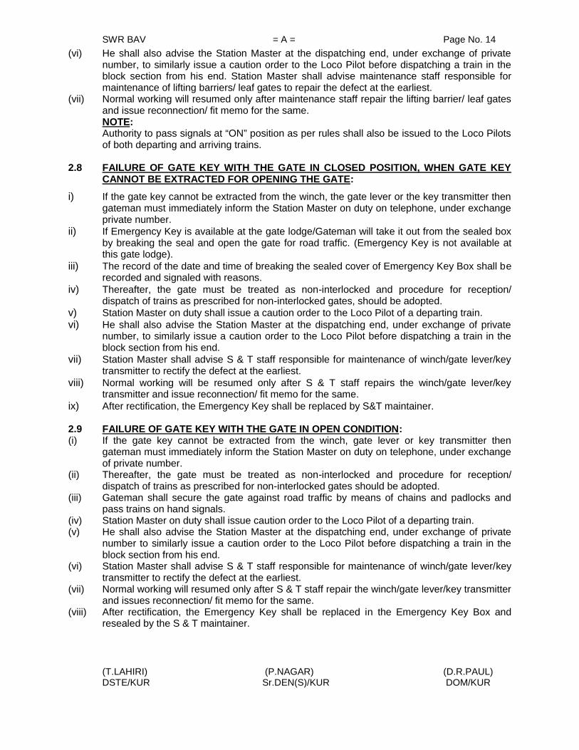
SWR BAV = A = Page No. 14
(T.LAHIRI) (P.NAGAR) (D.R.PAUL)DSTE/KUR Sr.DEN(S)/KUR DOM/KUR
(vi) He shall also advise the Station Master at the dispatching end, under exchange of privatenumber, to similarly issue a caution order to the Loco Pilot before dispatching a train in theblock section from his end. Station Master shall advise maintenance staff responsible formaintenance of lifting barriers/ leaf gates to repair the defect at the earliest.
(vii) Normal working will resumed only after maintenance staff repair the lifting barrier/ leaf gatesand issue reconnection/ fit memo for the same.NOTE:Authority to pass signals at “ON” position as per rules shall also be issued to the Loco Pilotsof both departing and arriving trains.
2.8 FAILURE OF GATE KEY WITH THE GATE IN CLOSED POSITION, WHEN GATE KEYCANNOT BE EXTRACTED FOR OPENING THE GATE:
i) If the gate key cannot be extracted from the winch, the gate lever or the key transmitter thengateman must immediately inform the Station Master on duty on telephone, under exchangeprivate number.
ii) If Emergency Key is available at the gate lodge/Gateman will take it out from the sealed boxby breaking the seal and open the gate for road traffic. (Emergency Key is not available atthis gate lodge).
iii) The record of the date and time of breaking the sealed cover of Emergency Key Box shall berecorded and signaled with reasons.
iv) Thereafter, the gate must be treated as non-interlocked and procedure for reception/dispatch of trains as prescribed for non-interlocked gates, should be adopted.
v) Station Master on duty shall issue a caution order to the Loco Pilot of a departing train.vi) He shall also advise the Station Master at the dispatching end, under exchange of private
number, to similarly issue a caution order to the Loco Pilot before dispatching a train in theblock section from his end.
vii) Station Master shall advise S & T staff responsible for maintenance of winch/gate lever/keytransmitter to rectify the defect at the earliest.
viii) Normal working will be resumed only after S & T staff repairs the winch/gate lever/keytransmitter and issue reconnection/ fit memo for the same.
ix) After rectification, the Emergency Key shall be replaced by S&T maintainer.
2.9 FAILURE OF GATE KEY WITH THE GATE IN OPEN CONDITION:(i) If the gate key cannot be extracted from the winch, gate lever or key transmitter then
gateman must immediately inform the Station Master on duty on telephone, under exchangeof private number.
(ii) Thereafter, the gate must be treated as non-interlocked and procedure for reception/dispatch of trains as prescribed for non-interlocked gates should be adopted.
(iii) Gateman shall secure the gate against road traffic by means of chains and padlocks andpass trains on hand signals.
(iv) Station Master on duty shall issue caution order to the Loco Pilot of a departing train.(v) He shall also advise the Station Master at the dispatching end, under exchange of private
number to similarly issue a caution order to the Loco Pilot before dispatching a train in theblock section from his end.
(vi) Station Master shall advise S & T staff responsible for maintenance of winch/gate lever/keytransmitter to rectify the defect at the earliest.
(vii) Normal working will resumed only after S & T staff repair the winch/gate lever/key transmitterand issues reconnection/ fit memo for the same.
(viii) After rectification, the Emergency Key shall be replaced in the Emergency Key Box andresealed by the S & T maintainer.

SWR BAV = A = Page No. 15
(T.LAHIRI) (P.NAGAR) (D.R.PAUL)DSTE/KUR Sr.DEN(S)/KUR DOM/KUR
2.10 OBSTRUCTION AT THE GATE:a. If the gate is broken by a road vehicle which is fouling the track or if lifting barriers/ leaf
gates or any other part of the gate foul the track, or if there is any other obstruction at thegate, the gateman shall immediately fix red banner flag by day and red lamp by night onposts provided at both ends of the gate, for this purpose.
b. Immediately after this, the gateman shall advise the Station Master on duty, regardingthe defects / obstructions at the gate, under exchange of private number.
c. Station Master on duty shall be advised to put the reception/departure signals back to‘ON’ position, if taken ‘OFF’ for a train.
d. If there is no response from the Station Master after two or three attempts, he shall firstprotect the gate and then inform on phone.
e. Gateman shall then rush with detonators, Battery operated LED based flashing lamp,and red flag by day and red hand signal lamp by night in the direction of the approachingtrain and protect gate vide GR.16.07.
f. Thereafter he shall protect the gate from the other direction also.g. He shall note down the particulars of the road vehicle, name of the Loco Pilot, owner and
relay these details to the Station Master who shall not start the train unless he has beenassured by the gateman that the road vehicle or the lifting barriers/ leaf gates are notfouling the track.
h. The Station Master shall also inform the Station Master at the dispatching end, underexchange of private number, asking him not to dispatch any train in the block sectionfrom his end, until the track has been cleared of all obstruction.
i. After the track has been cleared of all obstructions the gateman shall inform the StationMaster accordingly, under exchange of private number.
j. Station Master shall then issue a caution order to Loco Pilot of all trains to proceedcautiously, and pass the reception/departure signal at “ON” position on green handsignal of the gateman, if the gate is broken, but is clear of any obstruction.
k. Gateman shall secure the gate against road traffic by means of safety chains andpadlocks and there after exhibit green hand signal, if the gate is not obstructed.
l. Station Master shall advise maintenance staff responsible fir maintaining the liftingbarriers/leaf gate to repair the same at the earliest.
m. Normal working will be resumed only after maintenance staffs rectify the defective liftingbarriers/ leaf gates and issue reconnection/ fit memo for the same.
2.11 OBSTRUCTION ON THE TRACK NEAR LEVEL CROSSING GATE:If there is a rail fracture or obstruction on the track due to falling of a tree, fouling by roadvehicle or derailment which is visible to the gateman, the gateman and Station Masterwill adopt the procedure given under item No.2.10 above. If the obstruction fouls theLevel Crossing Gate, gate man must keep the gates closed against road traffic till thetrack is cleared of the obstruction.
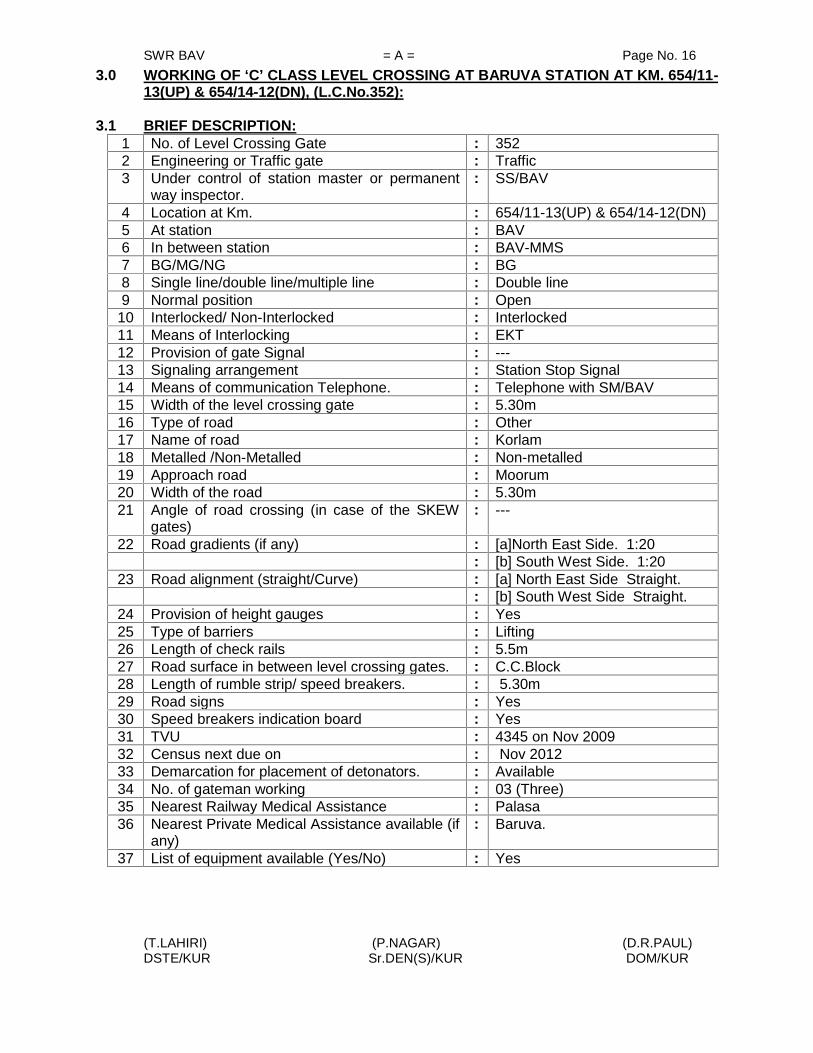
SWR BAV = A = Page No. 16
(T.LAHIRI) (P.NAGAR) (D.R.PAUL)DSTE/KUR Sr.DEN(S)/KUR DOM/KUR
3.0 WORKING OF ‘C’ CLASS LEVEL CROSSING AT BARUVA STATION AT KM. 654/11-13(UP) & 654/14-12(DN), (L.C.No.352):
3.1 BRIEF DESCRIPTION:1 No. of Level Crossing Gate : 3522 Engineering or Traffic gate : Traffic3 Under control of station master or permanent
way inspector.: SS/BAV
4 Location at Km. : 654/11-13(UP) & 654/14-12(DN)5 At station : BAV6 In between station : BAV-MMS7 BG/MG/NG : BG8 Single line/double line/multiple line : Double line9 Normal position : Open
10 Interlocked/ Non-Interlocked : Interlocked11 Means of Interlocking : EKT12 Provision of gate Signal : ---13 Signaling arrangement : Station Stop Signal14 Means of communication Telephone. : Telephone with SM/BAV15 Width of the level crossing gate : 5.30m16 Type of road : Other17 Name of road : Korlam18 Metalled /Non-Metalled : Non-metalled19 Approach road : Moorum20 Width of the road : 5.30m21 Angle of road crossing (in case of the SKEW
gates): ---
22 Road gradients (if any) : [a]North East Side. 1:20: [b] South West Side. 1:20
23 Road alignment (straight/Curve) : [a] North East Side Straight.: [b] South West Side Straight.
24 Provision of height gauges : Yes25 Type of barriers : Lifting26 Length of check rails : 5.5m27 Road surface in between level crossing gates. : C.C.Block28 Length of rumble strip/ speed breakers. : 5.30m29 Road signs : Yes30 Speed breakers indication board : Yes31 TVU : 4345 on Nov 200932 Census next due on : Nov 201233 Demarcation for placement of detonators. : Available34 No. of gateman working : 03 (Three)35 Nearest Railway Medical Assistance : Palasa36 Nearest Private Medical Assistance available (if
any): Baruva.
37 List of equipment available (Yes/No) : Yes

SWR BAV = A = Page No. 17
(T.LAHIRI) (P.NAGAR) (D.R.PAUL)DSTE/KUR Sr.DEN(S)/KUR DOM/KUR
3.2.A. EQUIPEMENT TO BE AVAILABLE AT THE GATE :
1. Battery Operated LED based flashing lamp 32. Hand Signal Flag Green 1 mounted on sticks3. Hand Signal Flag Red 34. Banner Flag Red 35. Posts for exhibiting red banner flag 26. Spare Chains with Padlocks 2 with stop mark7. Detonators 10 in tin case8. Gate lamps 29. Tommy Bar 110 Mortar Pan 111. Spade/ Fowrah 112. Pick Axe 113. Tin Case for Flags 114. Cane for oil 115. Water pot/Bucket 116. Canister for Muster roll 117. Set of spare spectacles of gateman wearing glasses 118. Board demarcating protection of level crossing gate
diagram in case of obstruction on gate1
19. Basket 120. Whistle 121. Wall clock 122. Small chain with pad lock 2
B. RECORDS TO BE KEPT AT GATE LODGEIn addition to the above equipment, following records shall also be kept at the GateLoge.
1. Gate Working Instructions in Hindi/English.2. Gate Working, Instructions in local vernacular language.3. Gateman Rule Book in local vernacular language.4. List for tools and books.5. Duty Roster.6. Certificate for working as gateman.7. Bio-data particulars of Gatemen, including date of passing vision test, initial/refresher
course, safety camp, etc.8. Accident Register.9. Record of last census of road traffic at Level Crossing gate.10. Public Complaint Book.11. Inspection Book.
3.3. INTERLOCKING AND NORMAL WORKING:This gate is interlocked with all DN reception signals and UP dispatch signals. Theinterlocking is achieved by means of Electrical Key Transmission System. The normalposition of the gate is open. A two-lever ground frame is provided at the gate lodge.The key of the L.C.Gate remains in the winch when the gate is opened. When it isnecessary to close the gate for taking off signals or for shunting operation the StationMaster on duty shall inform the Gateman to close and lock the gate.

SWR BAV = A = Page No. 18
(T.LAHIRI) (P.NAGAR) (D.R.PAUL)DSTE/KUR Sr.DEN(S)/KUR DOM/KUR
The Gateman on duty shall then close the barriers of the L.C.Gate by operating winch.The key ‘G’ is to be extracted from the winch, which will be inserted in the lever of GF-2.When GF-2 reversed locks the booms of the gates and Key ‘H’ and GF-1’ releases. Thiskey ‘H’ will be inserted in the EKT and turned and lever No.1GF will be reversed fortaking “OFF” DN Home/Calling-on Signals (2A/B/C, C-2A/B/C), UP Starter Signal No.5,9and shunt signal No-SH 4A/B. Station Master on duty will press level crossing controlbutton No.26 (Chocolate) and group button (release), L.C.Gate closed indication willappear in the panel and concerned signals automatically get released.
After the passage of train or completion of shunting the Station Master on duty shallinform the Gateman and press L.C.Gate controlling button No.26 and Common groupbutton (Trans) and keep it pressed till such time the Gateman extracts the gate controlkey ‘H’ from the EKT instrument. After getting the Key ‘G’ the Gateman will open theL.C.Gate by normalising the levers.
Emergency gate release operation facility is provided in the panel when the route getslocked due to some failure. For emergency release of gate, the SM on duty shall presssignal cancellation button and then emergency gate release button and gate buttonNo.26. A red flashing (Gate lock) indication will appear and after a lapse of 120sec. Gatelock indication will disappear and a white light will glow over the emergency gate releasebutton indicating that the operation is matured. The SM on duty shall then operate pushbutton for gate 26 and group Trans button to release the key from EKT in gate Lodge.All such operation will be registered in the emergency gate operation counter. All suchemergency operation shall be recorded in the station diary and in the register meant forit.
Lever No 1 is provided at the gate lodge to put back the any concerned signal to dangerin case of emergency by pulling the lever No 1 to normal position.
3.4. DUTIES OF GATEMAN:(1) ALERTNESS: The gateman shall be alert and be prepared to take immediate action,
should danger be apprehended. Keys of the gate shall be in his personal custody.
(2) POSITION DURING PASSAGE OF TRAINS:During passage of trains, gateman will stand in the manner indicated below:
(i) Gateman will stand attentively in front of the gate lodge facing the approaching train.(ii) In day time, gateman shall hold red and green flags furled up on separate sticks in right
and left hands respectively.(iii) In night time, gateman shall hold lighted hand signal lamp with white light facing the
track.(iv) He shall keep the whistle slung around his neck from a cord.
(3) ROUTINE DUTIES OF GATEMAN:i) Gateman shall place red banner flag during emergencies and obstruction on the track.ii) Gateman shall ensure that gate lamps and lamps of all gate signals are lighted and kept
burning continuously from sunset to sunrise.iii) Gateman shall perform his duties strictly according to the duty roster and shall not leave
the gate unless reliever arrives and takes charge of it. However, if it is necessary toleave the gate in an emergency, he must close and lock the gates against road traffic,before leaving the gate.

SWR BAV = A = Page No. 19
(T.LAHIRI) (P.NAGAR) (D.R.PAUL)DSTE/KUR Sr.DEN(S)/KUR DOM/KUR
iv) Except where otherwise prescribed under special instructions, he shall observe allpassing trains and be prepared to take such action as may be necessary to ensuresafety of trains.
v) Gateman shall watch all passing trains and keep sharp look out for any unusual like hotaxle, hanging chains, hanging battery, any vehicle / wagons / train / battery box on fire,shifted load, falling material like brake blocks, brake beams, safety bracket, vacuumcylinder or any other situation endangering safe running of trains.
vi) Gateman shall also be prepared to repeat any signal which guard may give to Loco Piloton walkie – talkie or in any other way.
vii) If lifting barriers / leaf gates get damaged or becomes out of order, the gateman shalluse the spare chain with disc and padlocks for securing the gate against road traffic.
viii) Gateman shall report to the nearest SM, Gangmate or Permanent Way Inspector anydefect in his gate or apparatus pertaining to it, as soon as possible.
ix) In the event of gate signal becoming defective the gateman shall maintain the signal inthe ‘ON’ position even by disconnecting the signal or the wire if necessary.
x) At the gate whose signal have become defective, the gateman shall close and lock andlifting barriers / leaf gates on sighting a train and hand signal or pilot the train past thedefective signal. In such case he should inform the Loco Pilot to report the defect at thenext station.
xi) Gateman shall wear badge and prescribed uniform while on duty at level crossing gate.xii) Gateman shall ensure that he is having competency certificate in his possession while
on duty.xiii) Gateman shall work the gate as per Gate Working Instructions and remain well
conversant with these instructions.xiv) Gateman shall ensure that equipment supplied at the gate is in good order and ready for
immediate use.xv) Gateman shall see that the channel for the flange of the wheel is kept clear.xvi) Gateman shall keep the road surface well watered and rammed in case of unmetalled
roads.xvii) Gateman must be vigilant to see that inconvenience to road users due to closure of
gates should be to the minimum possible extent.xviii) Gateman on electrified section shall watch that road vehicles / animals passing from
gate are within the height loading gauge provided on either side of the level crossinggate.
xix) Gateman shall prevent trespassing by persons or cattle to the maximum extent.
(4) ACTION IN CASE OF UNUSUAL OCCURRENCE ON TRAIN :In case gateman observes anything unusual with a passing train, he shall take followingaction.
(i) He shall take prompt action to warn the Loco Pilot / guard of the passing train byshowing red flag by day and red light by night.
(ii) He shall simultaneously try to draw the attention of the Loco Pilot / guard by whistlingcontinuously, shouting, gesticulating, throwing ballast on the brake van or by any othermeans.
(iii) If Loco Pilot/guard fails to take notice, gateman shall immediately inform the StationMaster, to take appropriate action, under exchange of private number.
(iv) In case of train parting, gateman shall not show stop hand signal but shall showprescribed signal for train parting.
(v) He shall endeavor to attract the attention of the Loco Pilot/guard by whistlingcontinuously, shouting, gesticulating and by raising both hands vertically above, quickly

SWR BAV = A = Page No. 20
(T.LAHIRI) (P.NAGAR) (D.R.PAUL)DSTE/KUR Sr.DEN(S)/KUR DOM/KUR
parting them and bringing them together in repeated Up and Down motion as high andas low as possible.
(vi) In case the train does not stop, gateman shall immediately inform the Station Master, ifconnected on telephone, to take appropriate action, under exchange of private number.
(5) ACTION IN AN EMERGENCY AT THE LEVEL CROSSING:i) In case of an obstruction at the level crossing gate, gateman shall maintain the gate
signals, in the ‘ON’ position.ii) Thereafter, if he is unable to remove the obstruction, gateman shall immediately advise
the Station Master on duty, regarding the defects/obstructions at the gate, underexchange of private number.
iii) If there is no response from the Station Master after two or three attempts, he shall firstprotect the gate and then inform on phone.The gateman shall protect the line as under:-
(c) ON DOUBLE LINE SECTION:i) If both lines are obstructed the gateman shall plant a red banner flag by day and a red
light by night 5 meters away on posts duly provided for the purpose. He shall firstprotect the line on which a train is expected to arrive first.
ii) The he will similarly plant the other red banner flag by day and red light by night on theother line 5 meters away from the site of obstruction.
iii) Gateman shall then proceed to protect the gate along with detonators, Battery operatedLED based flashing lamps and red flag by day and red hand signal lamp by night.
iv) Gateman shall proceed exhibiting red flag by day and red hand signal lamp by night onthe line on which a train is excepted to arrive first, to a point 600 meters on BG andplace one detonator on the line. Thereafter he shall proceed to a distance 1200 on BGfrom the level crossing gate and place 3 detonators on the track 10 meters apart. Havingthus protected the line he shall return to the level crossing gate picking up theintermediate detonator on his way back.
v) Thereafter, he shall proceed on the other line, showing red hand signal, similarly placedetonators as described in para (iv) above and return to the site of obstruction, pickingup the intermediate detonator on his way back.
vi) Having returned to the gate, he must then take steps to remove the obstruction and warnthe Loco Pilot of the approaching train.
vii) In case the gateman observes or hears a train approaching when he is still on his way toprotect and before he reaches the stipulated distance to place detonators, he shall placedetonators on the line at a distance as far away as he can go.
viii) Thereafter, he shall light up and fix the Battery operated LED based flashing lamp towarn the Loco Pilot and stop the approaching train by waving his red flag by day redhand signal lamp by night repeatedly.
(d) OTHER ACTION TO BE TAKEN BY GATEMAN:i) At night gateman shall light two hand signal lamps and take action to exhibit red light
and protect the lines as described in sub paras (a) above.ii) If the gate is broken by a road vehicle which is fouling the track, or if lifting barriers or
any other part of the gate foul the track, or if there is any other obstruction at the gate,the gateman shall take immediate action.
iii) He shall note down the particulars of the road vehicle, vehicle number, name of the LocoPilot, owner and relay these details to the nearest Station Master or Permanent WayInspector regarding the particulars and obstructions at the level crossing gate, throughmessenger or other means available.

SWR BAV = A = Page No. 21
(T.LAHIRI) (P.NAGAR) (D.R.PAUL)DSTE/KUR Sr.DEN(S)/KUR DOM/KUR
3.5 INTIMATION TO GATEMANi) Before taking off reception/departure/shunt signals, Station Master shall inform the
gateman , the number, description and direction of the train.ii) The gateman shall close the gate and transfer the key to the station master.iii) The reception/departure /shunt signals will be taken “OFF”.iv) In order to ensure that road traffic is not held up for a long time, the station master must
ensure that the train is ready for arrival/departure/shunting in all respects before headvises the gateman for closing the gate.
v) When a train has to be piloted to and from the station yard or any shunting movement isto be done, the staff deputed to pilot the trains or to perform the shunting across the gateshall be personally responsible to ensure that the gate is closed against road trafficbefore allowing any movement across the gate.
3.6 FAILURE OF TELEPHONE COMMUNICATION:When Telephonic Communication fails or it does not get any response from theGateman despite 2 or 3 attempts, the following procedure should be adopted:
i) Station Master on duty shall send written advice to the gateman through the porter withfull details of number, description and direction of the train.
ii) Gateman on receipt of such advice shall close the gate and transmit the key to theStation Master which will enable them to take “OFF” reception/ departure signals.
iii) When sufficient time is not available because of greater frequency of train service,Station Master will issue written authority to the train Loco Pilot to pass the signal at“ON” position.
iv) In addition Station Master shall also issue a caution order advising the Loco Pilot towhistle continuously and approach the gate cautiously.
v) The train Loco Pilot shall be instructed to pass the gate cautiously, on being handsignaled by the gateman. If hand signal is not seen, Loco Pilot should be prepared tostop short of the gate and ensure that gate is closed following GR 3.73 (2) (b).
vi) In case of an approaching train, the Station Master shall advise the Station Master at thedispatching end, under exchange of private number that the telephone at the gate hasfailed.
vii) The Station Master at the dispatching end shall then issue a caution order to the LocoPilot before dispatching a train in the block section from his end.
viii) He should also advise S & T staff responsible for maintenance of the telephone to rectifythe defect at the earliest.
ix) Normal working will be resumed only after S & T staff rectify the telephone and issuereconnection/ fit memo for the same.
3.7 FAILURE OF LIFTING BARRIERSi) When the gate cannot be closed due to failure of lifting barriers , the gateman will
immediately inform the Station Master on duty, under exchange of private number, andensure the lifting barriers or leaf gates do not foul the track.
ii) He shall immediately fix red banner flag by day and red light by night on the post at thatend first from which the train is approaching and then at the other end.
iii) Gateman shall secure the gate against road traffic by means of safety chains andpadlocks.
iv) After securing the gate against road traffic, gateman shall show green hand signal flagby day and green light to the Loco Pilot of the approaching train.
v) Station Master on duty shall issue caution order to the Loco Pilot of departing trains.

SWR BAV = A = Page No. 22
(T.LAHIRI) (P.NAGAR) (D.R.PAUL)DSTE/KUR Sr.DEN(S)/KUR DOM/KUR
vi) He shall also advise the Station Master at the dispatching end, under exchange of privatenumber, to similarly issue a caution order to the Loco Pilot before dispatching a train in theblock section from his end. Station Master shall advise maintenance staff responsible formaintenance of lifting barriers/ leaf gates to repair the defect at the earliest.
vii) Normal working will resumed only after maintenance staff repair the lifting barrier/ leaf gatesand issue reconnection/ fit memo for the same.
NOTE:Authority to pass signals at “ON” position as per rules shall also be issued to the Loco Pilotsof both departing and arriving trains.
3.8 FAILURE OF GATE KEY WITH THE GATE IN CLOSED POSITION, WHEN GATE KEYCANNOT BE EXTRACTED FOR OPENING THE GATE:
i) If the gate key cannot be extracted from the winch, the gate lever or the key transmitter thengateman must immediately inform the Station Master on duty on telephone, under exchangeprivate number.
ii) If Emergency Key is available at the gate lodge/Gateman will take it out from the sealed boxby breaking the seal and open the gate for road traffic. (Emergency key is not available atthis gate lodge).
iii) The record of the date and time of breaking the sealed cover of Emergency Key Box shall berecorded and signaled with reasons.
iv) Thereafter, the gate must be treated as non-interlocked and procedure for reception/dispatch of trains as prescribed for non-interlocked gates, should be adopted.
v) Station Master on duty shall issue a caution order to the Loco Pilot of a departing train.vi) He shall also advise the Station Master at the dispatching end, under exchange of private
number, to similarly issue a caution order to the Loco Pilot before dispatching a train in theblock section from his end.
vii) Station Master shall advise S & T staff responsible for maintenance of winch/gate lever/keytransmitter to rectify the defect at the earliest.
viii) Normal working will be resumed only after S & T staff repairs the winch/gate lever/keytransmitter and issue reconnection/ fit memo for the same.
ix) After rectification, the Emergency Key shall be replaced by S&T maintainer.
3.9 FAILURE OF GATE KEY WITH THE GATE IN OPEN CONDITION:i) If the gate key cannot be extracted from the winch, gate lever or key transmitter then
gateman must immediately inform the Station Master on duty on telephone, under exchangeof private number.
ii) Thereafter, the gate must be treated as non-interlocked and procedure for reception/dispatch of trains as prescribed for non-interlocked gates should be adopted.
iii) Gateman shall secure the gate against road traffic by means of chains and padlocks andpass trains on hand signals.
iv) Station Master on duty shall issue caution order to the Loco Pilot of a departing train.v) He shall also advise the Station Master at the dispatching end, under exchange of private
number to similarly issue a caution order to the Loco Pilot before dispatching a train in theblock section from his end.
vi) Station Master shall advise S & T staff responsible for maintenance of winch/gate lever/keytransmitter to rectify the defect at the earliest
vii) Normal working will resumed only after S & T staff repair the winch/gate lever/key transmitterand issues reconnection/ fit memo for the same.
viii) After rectification, the Emergency Key shall be replaced in the Emergency Key Box andresealed by the S & T maintainer.

SWR BAV = A = Page No. 23
(T.LAHIRI) (P.NAGAR) (D.R.PAUL)DSTE/KUR Sr.DEN(S)/KUR DOM/KUR
3.10 OBSTRUCTION AT THE GATE:i) If the gate is broken by a road vehicle which is fouling the track or if lifting barriers/ leaf
gates or any other part of the gate foul the track, or if there is any other obstruction at thegate, the gateman shall immediately fix red banner flag by day and red lamp by night onposts provided at both ends of the gate, for this purpose.
ii) Immediately after this, the gateman shall advise the Station Master on duty, regardingthe defects / obstructions at the gate, under exchange of private number.
iii) Station Master on duty shall be advised to put the reception/departure signals back to‘ON’ position, if taken ‘OFF’ for a train.
iv) If there is no response from the Station Master after two or three attempts, he shall firstprotect the gate and then inform on phone.
v) Gateman shall then rush with detonators, Battery operated LED based flashing lamp,and red flag by day and red hand signal lamp by night in the direction of the approachingtrain and protect gate vide GR.16.07.
vi) Thereafter he shall protect the gate from the other direction also.vii) He shall note down the particulars of the road vehicle, name of the Loco Pilot, owner and
relay these details to the Station Master who shall not start the train unless he has beenassured by the gateman that the road vehicle or the lifting barriers/ leaf gates are notfouling the track.
viii) The Station Master shall also inform the Station Master at the dispatching end, underexchange of private number, asking him not to dispatch any train in the block sectionfrom his end, until the track has been cleared of all obstruction.
ix) After the track has been cleared of all obstructions the gateman shall inform the StationMaster accordingly, under exchange of private number.
x) Station Master shall then issue a caution order to Loco Pilot of all trains to proceedcautiously, and pass the reception/departure signal at “ON” position on green handsignal of the gateman, if the gate is broken, but is clear of any obstruction.
xi) Gateman shall secure the gate against road traffic by means of safety chains andpadlocks and there after exhibit green hand signal, if the gate is not obstructed.
xii) Station Master shall advise maintenance staff responsible fir maintaining the liftingbarriers/leaf gate to repair the same at the earliest.
xiii) Normal working will be resumed only after maintenance staffs rectify the defective liftingbarriers/ leaf gates and issue reconnection/ fit memo for the same.
3.11 OBSTRUCTION ON THE TRACK NEAR LEVEL CROSSING GATE:If there is a rail fracture or obstruction on the track due to falling of a tree, fouling by roadvehicle or derailment which is visible to the gateman, the gateman and Station Masterwill adopt the procedure given under item No.3.10 above. If the obstruction fouls theLevel Crossing Gate, gate man must keep the gates closed against road traffic till thetrack is cleared of the obstruction.

SWR BAV = A = Page No. 24
(T.LAHIRI) (P.NAGAR) (D.R.PAUL)DSTE/KUR Sr.DEN(S)/KUR DOM/KUR
4.0 WORKING OF ‘SPL’ CLASS LEVEL CROSSING GATE AT BARUVA STATION ATKM. 655/27-29(UP) & 655/30-28(DN), (L.C.No.353)
4.1 BRIEF DESCRIPTION:1. No. of Level Crossing Gate 3532. Engineering or Traffic gate Engineering.3. Under control of station master or permanent
way inspector.SE/P.Way/SPT
4. Location at Km. 655/27-29(UP) & 655/30-28(DN)5. At station ---6. In between station BAV-MMS7. BG/MG/NG BG8. Single line/double line/multiple line Double line9. Normal position Open10. Interlocked/ Non-Interlocked Interlocked11. Means of Interlocking Gate Stop Signal12. Provision of gate signal at Km. Gate Stop Signal in both UP & DN
direction13. Signaling arrangement Gate Stop Signal in both UP & DN
direction14. Means of communication Telephone. Telephone with SS/BAV15. Width of the level crossing gate 8.22m16. Type of road NH17. Name of road Palasa18. Metalled /Non-Metalled Metaled19. Approach road Black Top20. Width of the road 8.22m21. Angle of road crossing (in case of the SKEW
gates)---
22. Road gradients (if any) [a]North/ East Side. Level[b] South/ West Side. Level
23. Road alignment (straight/Curve) [a] North /East Side Straight[b] South /West Side Straight
24. Provision of height gauges Yes25. Type of barriers Lifting26. Length of check rails 12.80m27. Road surface in between level crossing gates. Black Top28. Length of rumble strip/ speed breakers. 8.22m29. Road signs Yes30. Speed breakers indication board Yes31. TVU 53625 Nov 200932. Census next due on Nov 201233. Demarcation for placement of detonators. Available34. No. of gateman working Three35. Nearest Railway Medical Assistance Palasa36. Nearest Private Medical Assistance available (if
any)Baruva.
37. List of equipment available (Yes/No) YES

SWR BAV = A = Page No. 25
(T.LAHIRI) (P.NAGAR) (D.R.PAUL)DSTE/KUR Sr.DEN(S)/KUR DOM/KUR
4.2. A. EQUIPEMENT TO BE AVAILABLE AT THE GATE :1. Battery Operated LED based flashing lamp 32. Hand Signal Flag Green 1 mounted on sticks3. Hand Signal Flag Red 34. Banner Flag Red 35. Posts for exhibiting red banner flag 26. Spare Chains with Padlocks 2 with stop mark7. Detonators 10 in tin case8. Gate lamps 29. Tommy Bar 110 Mortar Pan 111. Spade/ Fowrah 112. Hammer 113. Pick Axe 114. Tin Case for Flags 115. Cane for oil 116. Water pot/Bucket 117. Canister for Muster roll 118. Set of spare spectacles of gateman wearing glasses 119. Board demarcating protection of level crossing gate
diagram in case of obstruction on gate1
20. Basket 121. Whistle 122. Wall clock 123. Small Chain with padlock 2
B. RECORDS TO BE KEPT AT GATE LODGEIn addition to the above equipment, following records shall also be kept at the GateLoge.
i) Gate Working Instructions in Hindi/English.ii) Gate Working, Instructions in local vernacular language.iii) Gateman Rule Book in local vernacular language.iv) List for tools and books.v) Duty Roster.vi) Certificate for working as gateman.vii) Bio-data particulars of Gatemen, including date of passing vision test, initial/refresher
course, safety camp, etc.viii) Accident Register.ix) Record of last census of road traffic at Level Crossing gate.x) Public Complaint Book.xi) Inspection Book.xii) S&T register.
4.3. INTERLOCKING AND NORMAL WORKING:This gate is interlocked with independent Gate Stop signals. The interlocking is achievedby mechanically Ground lever frame & closure of the L.C.Gate Boom. The normalposition of the gate is open. A five-lever ground frame is provided at the gate lodge.When it is necessary to close the gate for passage of a train, the SM on duty shall informthe Gateman to close and lock the gate. The function of the lever frames are illustratedbelow:

SWR BAV = A = Page No. 26
(T.LAHIRI) (P.NAGAR) (D.R.PAUL)DSTE/KUR Sr.DEN(S)/KUR DOM/KUR
Lever No.1 SpareLever No.2 Boom locking leverLever No.3 Up Gate Stop SignalLever No.4 Down Gate Stop SignalLever No.5 Spare
The Gateman on duty shall then close the barriers of the L.C.Gate by operating winch.The key ‘P’ is to be extracted from the winch, which will be inserted in the lever of GF-2.When GF-2 reversed locks the booms of the gates and releases UP and Down GateStop signals GF-3 & GF-4 respectively. After passage of the train this signal levers to benormalized and this lock lever to be made normal. This will be inserted in the winch andunlock to open the gate by operating the winch.
To avoid the detention to the road traffic at the Level crossing gate, the gate signalsshould not be taken off too early in advance and LC gate should not be kept closed formore than 10minutes at a stretch.
4.4. INTIMATION TO GATEMAN:i) Immediately after departure of the train, SM shall advise the gateman through telephone
connected at his end, the number, description, direction and expected time of thepassage of the train at the gate.
ii) If the actually running time of the train from either end of the section is less than 10minutes, SM will convey this advise to the gateman before obtaining /granting line clear.
iii) It should be the duty of the gateman to ensure that the gate is closed in time, so thatthere is no detention to the train or excessive detention to road traffic.
4.5 DUTIES OF GATEMAN:
1) ALERTNESS:The gateman shall be alert and be prepared to take immediate action, should danger beapprehended. Keys of the gate shall be in his personal custody.
2) POSITION DURING PASSAGE OF TRAINS:During passage of trains, gateman will stand in the manner indicated below:
i) Gateman will stand attentively in front of the gate lodge facing the approaching train.ii) In day time, gateman shall hold red and green flags furled up on separate sticks in right
and left hands respectively.iii) In night time, gateman shall hold lighted hand signal lamp with white light facing the
track.iv) He shall keep the whistle slung around his neck from a cord.
3) ROUTINE DUTIES OF GATEMAN:i) Gateman shall place red banner flag during emergencies and obstruction on the track.ii) Gateman shall ensure that gate lamps and lamps of all gate signals are lighted and kept
burning continuously from sunset to sunrise.

SWR BAV = A = Page No. 27
(T.LAHIRI) (P.NAGAR) (D.R.PAUL)DSTE/KUR Sr.DEN(S)/KUR DOM/KUR
iii) Gateman shall perform his duties strictly according to the duty roster and shall not leavethe gate unless reliever arrives and takes charge of it. However, if it is necessary toleave the gate in an emergency, he must close and lock the gates against road traffic,before leaving the gate.
iv) Except where otherwise prescribed under special instructions, he shall observe allpassing trains and be prepared to take such action as may be necessary to ensuresafety of trains.
v) Gateman shall watch all passing trains and keep sharp look out for any unusual like hotaxle, hanging chains, hanging battery, any vehicle / wagons / train / battery box on fire,shifted load, falling material like brake blocks, brake beams, safety bracket, vacuumcylinder or any other situation endangering safe running of trains.
vi) Gateman shall also be prepared to repeat any signal which guard may give to Loco Piloton walkie – talkie or in any other way.
vii) If lifting barriers / leaf gates get damaged or becomes out of order, the gateman shalluse the spare chain with disc and padlocks for securing the gate against road traffic.
viii) Gateman shall report to the nearest SM, Gangmate or Permanent Way Inspector anydefect in his gate or apparatus pertaining to it, as soon as possible.
ix) In the event of gate signal becoming defective the gateman shall maintain the signal inthe ‘ON’ position even by disconnecting the signal or the wire if necessary.
x) At the gate whose signal have become defective, the gateman shall close and lock andlifting barriers / leaf gates on sighting a train and hand signal or pilot the train past thedefective signal. In such case he should inform the Loco Pilot to report the defect at thenext station.
xi) Gateman shall wear badge and prescribed uniform while on duty at level crossing gate.xii) Gateman shall ensure that he is having competency certificate in his possession while
on duty.xiii) Gateman shall work the gate as per Gate Working Instructions and remain well
conversant with these instructions.xiv) Gateman shall ensure that equipment supplied at the gate is in good order and ready for
immediate use.xv) Gateman shall see that the channel for the flange of the wheel is kept clear.xvi) Gateman shall keep the road surface well watered and rammed in case of unmetalled
roads.xvii) Gateman must be vigilant to see that inconvenience to road users due to closure of
gates should be to the minimum possible extent.xviii) Gateman on electrified section shall watch that road vehicles / animals passing from
gate are within the height loading gauge provided on either side of the level crossinggate.
xix) Gateman shall prevent trespassing by persons or cattle to the maximum extent.
4) ACTION IN CASE OF UNUSUAL OCCURRENCE ON TRAIN :In case gateman observes anything unusual with a passing train, he shall take followingaction.
i) He shall take prompt action to warn the Loco Pilot / guard of the passing train byshowing red flag by day and red light by night.
ii) He shall simultaneously try to draw the attention of the Loco Pilot / guard by whistlingcontinuously, shouting, gesticulating, throwing ballast on the brake van or by any othermeans.

SWR BAV = A = Page No. 28
(T.LAHIRI) (P.NAGAR) (D.R.PAUL)DSTE/KUR Sr.DEN(S)/KUR DOM/KUR
iii) If Loco Pilot/guard fails to take notice, gateman shall immediately inform the StationMaster, if connected on telephone, to take appropriate action, under exchange of privatenumber.
iv) In case of train parting, gateman shall not show stop hand signal but shall showprescribed signal for train parting.
v) He shall endeavor to attract the attention of the Loco Pilot/guard by whistlingcontinuously, shouting, gesticulating and by raising both hands vertically above, quicklyparting them and bringing them together in repeated Up and Down motion as high andas low as possible.
vi) In case the train does not stop, gateman shall immediately inform the Station Master, ifconnected on telephone, to take appropriate action, under exchange of private number.
5) ACTION IN AN EMERGENCY AT THE LEVEL CROSSING:i) In case of an obstruction at the level crossing gate, gateman shall maintain the gate
signals, if any, in the ‘ON’ position.ii) Thereafter, if he is unable to remove the obstruction, gateman shall immediately advise
the Station Master on duty, if connecting by telephone, regarding thedefects/obstructions at the gate, under exchange of private number.
iii) If there is no response from the Station Master after two or three attempts, he shall firstprotect the gate and then inform on phone.
a) The gateman shall protect the line as under:-i) If both lines are obstructed the gateman shall plant a red banner flag by day and a red
light by night 5 meters away on posts duly provided for the purpose. He shall firstprotect the line on which a train is expected to arrive first.
ii) Then he will similarly plant the other red banner flag by day and red light by night on theother line 5 meters away from the site of obstruction.
iii) Gateman shall then proceed to protect the gate along with detonators, Battery OperatedLED based flashing lamps and red flag by day and red hand signal lamp by night.
iv) Gateman shall proceed exhibiting red flag by day and red hand signal lamp by night onthe line on which a train is expected to arrive first, to a point 600 meters on BG andplace one detonator on the line. Thereafter he shall proceed to a distance 1200 on BGfrom the level crossing gate and place 3 detonators on the track 10 meters apart. Havingthus protected the line he shall return to the level crossing gate picking up theintermediate detonator on his way back.
v) Thereafter, he shall proceed on the other line, showing red hand signal, similarly placedetonators as described in para (iv) above and return to the site of obstruction, pickingup the intermediate detonator on his way back.
vi) Having returned to the gate, he must then take steps to remove the obstruction and warnthe Loco Pilot of the approaching train.
vii) In case the gateman observes or hears a train approaching when he is still on his way toprotect and before he reaches the stipulated distance to place detonators, he shall placedetonators on the line at a distance as far away as he can go.
viii) Thereafter, he shall light up and fix the Battery Operated LED based flashing lamp towarn the Loco Pilot and stop the approaching train by waving his red flag by day redhand signal lamp by night repeatedly.
(b) OTHER ACTION TO BE TAKEN BY GATEMAN:i) At night gateman shall light two hand signal lamps and take action to exhibit red light
and protect the lines as described in sub paras (a) and (b) above.

SWR BAV = A = Page No. 29
(T.LAHIRI) (P.NAGAR) (D.R.PAUL)DSTE/KUR Sr.DEN(S)/KUR DOM/KUR
ii) If the gate is broken by a road vehicle which is fouling the track, or if lifting barriers / leafgates or any other part of the gate foul the track, or if there is any other obstruction at thegate, the gateman shall take immediate action.
iii) He shall note down the particulars of the road vehicle, vehicle number, name of the LocoPilot, owner and relay these details to the nearest Station Master or Permanent WayInspector regarding the particulars and obstructions at the level crossing gate, throughmessenger or other means available.
4.6 FAILURE OF TELEPHONIC COMMUNICATION:When Telephonic Communication fails or it does not get any response from theGateman despite 2 or 3 attempts, the following procedure should be adopted:
i) If the telephone fails at the gate connected with the Station at the dispatching end,station master shall then issue a caution order to the Loco Pilot of the departing train.
ii) Station master shall advise the Loco Pilot to whistle continuously and proceed cautiouslywhile approaching the gate.
iii) In case the gate signal is ON he should stop short of gate signal and follow theprocedure laid under GR 3.73.
iv) In case of an approaching train, the Station Master shall advise the Station Master at thedispatching end, under exchange of private number that the telephone at the gate hasfailed.
v) The Station Master at the dispatching end shall then issue a caution order to the LocoPilot before dispatching a train in the block section from his end.
vi) Station master will also advise the gateman through gang man/patrolman/Loco Pilot ofthe first train that the telephone has become defective.
vii) Station master should also advise S & T staff responsible for maintenance of thetelephone to rectify the defect at the earliest.
viii) Normal working will be resumed only after S & T staff rectify the telephone and issuereconnection/ fit memo for the same.
4.7 FAILURE OF LIFTING BARRIERS OR LEAF GATES:i) When the gate cannot be closed due to failure of lifting barriers or leaf gates, the
gateman will immediately inform the Station Master on duty, under exchange of privatenumber, and ensure the lifting barriers or leaf gates do not foul the track.
ii) He shall immediately fix red banner flag by day and red light by night on the post at thatend first from which the train is approaching and then at the other end.
iii) Gateman shall secure the gate against road traffic by means of safety chains andpadlocks.
iv) After securing the gate against road traffic, gateman shall show green hand signal flagby day and green light to the Loco Pilot of the approaching train.
v) Station Master on duty shall issue caution order to the Loco Pilot of departing trains.vi) He shall also advise the Station Master at the dispatching end, under exchange of
private number, to similarly issue a caution order to the Loco Pilot before dispatching atrain in the block section from his end.
vii) Station Master shall advise maintenance staff responsible for maintenance of liftingbarriers/ leaf gates to repair the defect at the earliest.
viii) Normal working will resumed only after maintenance staff repair the lifting barrier/ leafgates and issue reconnection/ fit memo for the same.
NOTE:Authority to pass signals at “ON” position as per rules shall also be issued to the LocoPilots of both departing and arriving trains.

SWR BAV = A = Page No. 30
(T.LAHIRI) (P.NAGAR) (D.R.PAUL)DSTE/KUR Sr.DEN(S)/KUR DOM/KUR
4.8 FAILURE OF GATE KEY WITH THE GATE IN CLOSED POSITION, WHEN GATEKEY CANNOT BE EXTRACTED FOR OPENING THE GATE:
i) If the gate key cannot be extracted from the winch, the gate leaves or the key transmitterthen gateman must immediately inform the Station Master on duty on telephone, underexchange private number.
ii) If Emergency Key is available at the gate lodge/Gateman will take it out from the sealedbox by breaking the seal and open the gate for road traffic. ( In this gate the emergencykey is not available)
iii) Thereafter, the gate must be treated as non-interlocked and procedure for reception/dispatch of trains as prescribed for non-interlocked gates, should be adopted.
iv) Station Master on duty shall issue a caution order to the Loco Pilot of a departing train.v) He shall also advise the Station Master at the dispatching end, under exchange of
private number, to similarly issue a caution order to the Loco Pilot before dispatching atrain in the block section from his end.
vi) Station Master shall advise S & T staff responsible for maintenance of winch/gateleaves/key transmitter to rectify the defect at the earliest.
vii) Normal working will be resumed only after S & T staff repairs the winch/gate leaves/keytransmitter and issue reconnection/ fit memo for the same.
4.9 FAILURE OF GATE KEY WITH THE GATE IN OPEN CONDITION:i) If the gate key cannot be extracted from the winch, gate lever or key transmitter then
gateman must immediately inform the Station Master on duty on telephone, underexchange of private number.
ii) Thereafter, the gate must be treated as non-interlocked and procedure for reception/dispatch of trains as prescribed for non-interlocked gates should be adopted.
iii) Gateman shall secure the gate against road traffic by means of chains and padlocks andpass trains on hand signals.
iv) Station Master on duty shall issue caution order to the Loco Pilot of a departing train.v) He shall also advise the Station Master at the dispatching end, under exchange of
private number to similarly issue a caution order to the Loco Pilot before dispatching atrain in the block section from his end.
vi) Station Master shall advise S & T staff responsible for maintenance of winch/gateleaves/key transmitter to rectify the defect at the earliest
vii) Normal working will resumed only after S & T staff repair the winch/gate leaves/keytransmitter and issues reconnection/ fit memo for the same.
4.10 DEFECTIVE GATE SIGNALS:i) The gateman shall treat the gate signal as defective and must not lower them under
following circumstances:ii) If gate signals can be taken “OFF” without closing the gate, oriii) The key can be extracted from the operating winch when the gate is in open condition,
oriv) If the Gate or the Gate Signal or Distant Signal becomes defective in “OFF” position, the
gateman will make all efforts to put it at “ON” position even by cutting signal wires, ifnecessary.
v) The gateman will immediately advise the Station Master on duty, under exchange ofprivate number, regarding defective gate signals.
vi) Thereafter, the gate must be treated as non interlocked and procedure for reception/dispatch of trains as prescribed for non-interlocked gates should be adopted.

SWR BAV = A = Page No. 31
(T.LAHIRI) (P.NAGAR) (D.R.PAUL)DSTE/KUR Sr.DEN(S)/KUR DOM/KUR
vii) He shall show green hand signal flag by day and green light by night to the passing trainafter closing the gate.
viii) Station Master on duty will issue caution order to the Loco Pilot of a departing train.ix) He shall also advise the Station Master at the dispatching end, under exchange of
private number; to similarly issue a caution order to the Loco Pilot before dispatching atrain in the block section from his end.
x) Station Master shall advise S & T staff responsible for maintaining the gate signal torepair the same at the earliest
xi) Normal working will be resumed after S & T staff rectifies the defective gate signal andissue reconnection/ fit memo for the same.
4.11 OBSTRUCTION AT THE GATE:i) If the gate is broken by a road vehicle which is fouling the track or if lifting barriers/ leaf
gates or any other part of the gate foul the track, or if there is any other obstruction at thegate, the gateman shall immediately fix red banner flag by day and red lamp by night onposts provided at both ends of the gate, for this purpose.
ii) Immediately after this, the gateman shall advise the Station Master on duty, regardingthe defects / obstructions at the gate, under exchange of private number.
iii) Station Master on duty shall be advised to put the reception/departure signals back to‘ON’ position, if taken ‘OFF’ for a train.
iv) If there is no response from the Station Master after two or three attempts, he shall firstprotect the gate and then inform on phone.
v) Gateman shall then rush with detonators, Battery Operated LED based flashing lamp,and red flag by day and red hand signal lamp by night in the direction of the approachingtrain and protect gate vide GR.16.07.
vi) Thereafter he shall protect the gate from the other direction also.vii) He shall note down the particulars of the road vehicle, name of the Loco Pilot, owner and
relay these details to the Station Master who shall not start the train unless he has beenassured by the gateman that the road vehicle or the lifting barriers/ leaf gates are notfouling the track.
viii) The Station Master shall also inform the Station Master at the dispatching end, underexchange of private number, asking him not to dispatch any train in the block sectionfrom his end, until the track has been cleared of all obstruction.
ix) After the track has been cleared of all obstructions the gateman shall inform the StationMaster accordingly, under exchange of private number.
x) Station Master shall then issue a caution order to Loco Pilot of all trains to proceedcautiously, and pass the reception/departure signal at “ON” position on green handsignal of the gateman, if the gate is broken, but is clear of any obstruction.
xi) Gateman shall secure the gate against road traffic by means of safety chains andpadlocks and there after exhibit green hand signal, if the gate is not obstructed.
xii) Station Master shall advise maintenance staff responsible fir maintaining the liftingbarriers/leaf gate to repair the same at the earliest.
xiii) Normal working will be resumed only after maintenance staffs rectify the defective liftingbarriers/ leaf gates and issue reconnection/ fit memo for the same.
4.12 OBSTRUCTION ON THE TRACK NEAR LEVEL CROSSING GATE:If there is a rail fracture or obstruction on the track due to falling of a tree, fouling by roadvehicle or derailment which is visible to the gateman, the gateman and Station Masterwill adopt the procedure given under item No.4.11 above. If the obstruction fouls theLevel Crossing Gate, gate man must keep the gates closed against road traffic till thetrack is cleared of the obstruction.

SWR BAV = A = Page No. 32
(T.LAHIRI) (P.NAGAR) (D.R.PAUL)DSTE/KUR Sr.DEN(S)/KUR DOM/KUR
5.0 WORKING OF ‘A’ CLASS LEVEL CROSSING GATE AT BARUVA STATION AT KM.657/27-29(UP) & 657/30-28(DN), (L.C.No.354).
5.1 BRIEF DESCRIPTION:1. No. of Level Crossing Gate : 3542. Engineering or Traffic gate : Engineering.3. Under control of station master or permanent
way inspector.: SE/P.Way/SPT
4. Location at Km. : KM. 657/27-29(UP) & 657/30-28(DN)5. At station : ---6. In between station : BAV-MMS7. BG/MG/NG : BG8. Single line/double line/multiple line : Double line9. Normal position : Open10. Interlocked/ Non-Interlocked : Interlocked11. Means of Interlocking : Gate Stop Signal12. Provision of gate signal at Km. : UP Gate Stop Signals in both UP and
DN directions.13. Signaling arrangement : UP Gate Stop Signals in both UP and
DN directions.14. Means of communication Telephone. : Telephone with SS/BAV15. Width of the level crossing gate : 4.55m16. Type of road : Others17. Name of road : Kathapalli18. Metalled /Non-Metalled : Metalled19. Approach road : Black Top20. Width of the road : 4.55m21. Angle of road crossing (in case of the SKEW
gates): ---
22. Road gradients (if any) : [a]North/ East Side. 1:30: [b] South/ West Side. 1:25
23. Road alignment (straight/Curve) : [a] North /East Side Straight: [b] South /West Side Straight
24. Provision of height gauges : Yes25. Type of barriers : Lifting26. Length of check rails : 7.50m27. Road surface in between level crossing gates. : Black Top28. Length of rumble strip/ speed breakers. : 4.55m29. Road signs : Yes30. Speed breakers indication board : Yes31. TVU : 9900 Nov 200932. Census next due on : Nov 201233. Demarcation for placement of detonators. : Available34. No. of gateman working : Three35. Nearest Railway Medical Assistance : Palasa36. Nearest Private Medical Assistance available (if
any): Mandasa Road.
37. List of equipment available (Yes/No) : YES

SWR BAV = A = Page No. 33
(T.LAHIRI) (P.NAGAR) (D.R.PAUL)DSTE/KUR Sr.DEN(S)/KUR DOM/KUR
5.2. A. EQUIPEMENT TO BE AVAILABLE AT THE GATE :1. Battery Operated LED based flashing lamp 32. Hand Signal Flag Green 1 mounted on sticks3. Hand Signal Flag Red 34. Banner Flag Red 35. Posts for exhibiting red banner flag 26. Spare Chains with Padlocks 2 with stop mark7. Detonators 10 in tin case8. Gate lamps 29. Tommy Bar 110 Mortar Pan 111. Spade/ Fowrah 112. Rammer 113. Pick Axe 114. Tin Case for Flags 115. Cane for oil 116. Water pot/Bucket 117. Canister for Muster roll 118. Set of spare spectacles of gateman wearing glasses 119. Board demarcating protection of level crossing gate
diagram in case of obstruction on gate1
20. Basket 121. Whistle 122. Wall clock 123. Small chain with padlock
B. RECORDS TO BE KEPT AT GATE LODGEIn addition to the above equipment, following records shall also be kept at the GateLoge.
i) Gate Working Instructions in Hindi/English.ii) Gate Working, Instructions in local vernacular language.iii) Gateman Rule Book in local vernacular language.iv) List for tools and books.v) Duty Roster.vi) Certificate for working as gateman.vii) Bio-data particulars of Gatemen, including date of passing vision test, initial/refresher
course, safety camp, etc.viii) Accident Register.ix) Record of last census of road traffic at Level Crossing gate.x) Public Complaint Book.xi) Inspection Book.xii) S&T register.
5.3. INTERLOCKING AND NORMAL WORKING:This gate is interlocked with independent Gate Home signals. The interlocking isachieved by mechanically Ground lever frame & closure of the L.C.Gate Boom. Thenormal position of the gate is open. A four-lever ground frame is provided at the gatelodge. When it is necessary to close the gate for passage of a train, the SM on dutyshall inform the Gateman to close and lock the gate.
SWR BAV = A = Page No. 34
(T.LAHIRI) (P.NAGAR) (D.R.PAUL)DSTE/KUR Sr.DEN(S)/KUR DOM/KUR
The Gateman on duty shall then close the barriers of the L.C.Gate by operating winch.The key ‘G’ is to be extracted from the winch, which will be inserted in the lever of GF-2.When GF-2 reversed locks the booms of the gates and releases UP and Down GateHome signals GF-3 & GF-4 respectively. After passage of the train this signal levers tobe normalized and this lock lever to be made normal. This will be inserted in the winchand unlock to open the gate by operating the winch.
To avoid the detention to the road traffic at the Level crossing gate, the gate signalsshould not be taken off too early in advance and LC gate should not be kept closed formore than 10minutes at a stretch.
5.4. INTIMATION TO GATEMANi) Immediately after departure of the train, SM shall advise the gateman through telephone
connected at his end, the number, description, direction and expected time of thepassage of the train at the gate.
ii) If the actually running time of the train from either end of the section is less than 10minutes, SM will convey this advise to the gateman before obtaining /granting line clear.
iii) It should be the duty of the gateman to ensure that the gate is closed in time, so thatthere is no detention to the train or excessive detention to road traffic.
5.5 DUTIES OF GATEMAN:
1) ALERTNESS:The gateman shall be alert and be prepared to take immediate action, should danger beapprehended. Keys of the gate shall be in his personal custody.
2) POSITION DURING PASSAGE OF TRAINS:During passage of trains, gateman will stand in the manner indicated below:
i) Gateman will stand attentively in front of the gate lodge facing the approaching train.ii) In day time, gateman shall hold red and green flags furled up on separate sticks in right
and left hands respectively.iii) In night time, gateman shall hold lighted hand signal lamp with white light facing the
track.iv) He shall keep the whistle slung around his neck from a cord.
3) ROUTINE DUTIES OF GATEMAN:i) Gateman shall place red banner flag during emergencies and obstruction on the track.ii) Gateman shall ensure that gate lamps and lamps of all gate signals are lighted and kept
burning continuously from sunset to sunrise.iii) Gateman shall perform his duties strictly according to the duty roster and shall not leave
the gate unless reliever arrives and takes charge of it. However, if it is necessary toleave the gate in an emergency, he must close and lock the gates against road traffic,before leaving the gate.
iv) Except where otherwise prescribed under special instructions, he shall observe allpassing trains and be prepared to take such action as may be necessary to ensuresafety of trains.
v) Gateman shall watch all passing trains and keep sharp look out for any unusual like hotaxle, hanging chains, hanging battery, any vehicle / wagons / train / battery box on fire,shifted load, falling material like brake blocks, brake beams, safety bracket, vacuumcylinder or any other situation endangering safe running of trains.

SWR BAV = A = Page No. 35
(T.LAHIRI) (P.NAGAR) (D.R.PAUL)DSTE/KUR Sr.DEN(S)/KUR DOM/KUR
vi) Gateman shall also be prepared to repeat any signal which guard may give to Loco Piloton walkie – talkie or in any other way.
vii) If lifting barriers / leaf gates get damaged or becomes out of order, the gateman shalluse the spare chain with disc and padlocks for securing the gate against road traffic.
viii) Gateman shall report to the nearest SM, Gangmate or Permanent Way Inspector anydefect in his gate or apparatus pertaining to it, as soon as possible.
ix) In the event of gate signal becoming defective the gateman shall maintain the signal inthe ‘ON’ position even by disconnecting the signal or the wire if necessary.
x) At the gate whose signal have become defective, the gateman shall close and lock andlifting barriers / leaf gates on sighting a train and hand signal or pilot the train past thedefective signal. In such case he should inform the Loco Pilot to report the defect at thenext station.
xi) Gateman shall wear badge and prescribed uniform while on duty at level crossing gate.xii) Gateman shall ensure that he is having competency certificate in his possession while
on duty.xiii) Gateman shall work the gate as per Gate Working Instructions and remain well
conversant with these instructions.xiv) Gateman shall ensure that equipment supplied at the gate is in good order and ready for
immediate use.xv) Gateman shall see that the channel for the flange of the wheel is kept clear.xvi) Gateman shall keep the road surface well watered and rammed in case of unmetalled
roads.xvii) Gateman must be vigilant to see that inconvenience to road users due to closure of
gates should be to the minimum possible extent.xviii) Gateman on electrified section shall watch that road vehicles / animals passing from
gate are within the height loading gauge provided on either side of the level crossinggate.
xix) Gateman shall prevent trespassing by persons or cattle to the maximum extent.
4) ACTION IN CASE OF UNUSUAL OCCURRENCE ON TRAIN :In case gateman observes anything unusual with a passing train, he shall take followingaction.
i) He shall take prompt action to warn the Loco Pilot / guard of the passing train byshowing red flag by day and red light by night.
ii) He shall simultaneously try to draw the attention of the Loco Pilot / guard by whistlingcontinuously, shouting, gesticulating, throwing ballast on the brake van or by any othermeans.
iii) If Loco Pilot/guard fails to take notice, gateman shall immediately inform the StationMaster, if connected on telephone, to take appropriate action, under exchange of privatenumber.
iv) In case of train parting, gateman shall not show stop hand signal but shall showprescribed signal for train parting.
v) He shall endeavor to attract the attention of the Loco Pilot/guard by whistlingcontinuously, shouting, gesticulating and by raising both hands vertically above, quicklyparting them and bringing them together in repeated Up and Down motion as high andas low as possible.
vi) In case the train does not stop, gateman shall immediately inform the Station Master, ifconnected on telephone, to take appropriate action, under exchange of private number.

SWR BAV = A = Page No. 36
(T.LAHIRI) (P.NAGAR) (D.R.PAUL)DSTE/KUR Sr.DEN(S)/KUR DOM/KUR
5) ACTION IN AN EMERGENCY AT THE LEVEL CROSSING:i) In case of an obstruction at the level crossing gate, gateman shall maintain the gate
signals, if any, in the ‘ON’ position.ii) Thereafter, if he is unable to remove the obstruction, gateman shall immediately advise
the Station Master on duty, if connecting by telephone, regarding thedefects/obstructions at the gate, under exchange of private number.
iii) If there is no response from the Station Master after two or three attempts, he shall firstprotect the gate and then inform on phone.
a) The gateman shall protect the line as under:-i) If both lines are obstructed the gateman shall plant a red banner flag by day and a red
light by night 5 meters away on posts duly provided for the purpose. He shall firstprotect the line on which a train is expected to arrive first.
ii) Then he will similarly plant the other red banner flag by day and red light by night on theother line 5 meters away from the site of obstruction.
iii) Gateman shall then proceed to protect the gate along with detonators, Battery OperatedLED based flashing lamps and red flag by day and red hand signal lamp by night.
iv) Gateman shall proceed exhibiting red flag by day and red hand signal lamp by night onthe line on which a train is expected to arrive first, to a point 600 meters on BG andplace one detonator on the line. Thereafter he shall proceed to a distance 1200 on BGfrom the level crossing gate and place 3 detonators on the track 10 meters apart. Havingthus protected the line he shall return to the level crossing gate picking up theintermediate detonator on his way back.
v) Thereafter, he shall proceed on the other line, showing red hand signal, similarly placedetonators as described in para (iv) above and return to the site of obstruction, pickingup the intermediate detonator on his way back.
vi) Having returned to the gate, he must then take steps to remove the obstruction and warnthe Loco Pilot of the approaching train.
vii) In case the gateman observes or hears a train approaching when he is still on his way toprotect and before he reaches the stipulated distance to place detonators, he shall placedetonators on the line at a distance as far away as he can go.
viii) Thereafter, he shall light up and fix the Battery Operated LED based flashing lamp towarn the Loco Pilot and stop the approaching train by waving his red flag by day redhand signal lamp by night repeatedly.
(b) Other action to be taken by Gateman:i) At night gateman shall light two hand signal lamps and take action to exhibit red light
and protect the lines as described in sub paras (a) and (b) above.ii) If the gate is broken by a road vehicle which is fouling the track, or if lifting barriers / leaf
gates or any other part of the gate foul the track, or if there is any other obstruction at thegate, the gateman shall take immediate action.

SWR BAV = A = Page No. 37
(T.LAHIRI) (P.NAGAR) (D.R.PAUL)DSTE/KUR Sr.DEN(S)/KUR DOM/KUR
iii) He shall note down the particulars of the road vehicle, vehicle number, name of the LocoPilot, owner and relay these details to the nearest Station Master or Permanent WayInspector regarding the particulars and obstructions at the level crossing gate, throughmessenger or other means available.
5.6 FAILURE OF TELEPHONIC COMMUNICATION:When Telephonic Communication fails or it does not get any response from theGateman despite 2 or 3 attempts, the following procedure should be adopted:
i) If the telephone fails at the gate connected with the Station at the dispatching end,station master shall then issue a caution order to the Loco Pilot of the departing train.
ii) Station master shall advise the Loco Pilot to whistle continuously and proceed cautiouslywhile approaching the gate.
iii) In case the gate signal is ON he should stop short of gate signal and follow theprocedure laid under GR 3.73.
iv) In case of an approaching train, the Station Master shall advise the Station Master at thedispatching end, under exchange of private number that the telephone at the gate hasfailed.
v) The Station Master at the dispatching end shall then issue a caution order to the LocoPilot before dispatching a train in the block section from his end.
vi) Station master will also advise the gateman through gang man/patrolman/Loco Pilot ofthe first train that the telephone has become defective.
vii) Station master should also advise S & T staff responsible for maintenance of thetelephone to rectify the defect at the earliest.
viii) Normal working will be resumed only after S & T staff rectify the telephone and issuereconnection/ fit memo for the same.
5.7 FAILURE OF LIFTING BARRIERS OR LEAF GATES:i) When the gate cannot be closed due to failure of lifting barriers or leaf gates, the
gateman will immediately inform the Station Master on duty, under exchange of privatenumber, and ensure the lifting barriers or leaf gates do not foul the track.
ii) He shall immediately fix red banner flag by day and red light by night on the post at thatend first from which the train is approaching and then at the other end.
iii) Gateman shall secure the gate against road traffic by means of safety chains andpadlocks.
iv) After securing the gate against road traffic, gateman shall show green hand signal flagby day and green light to the Loco Pilot of the approaching train.
v) Station Master on duty shall issue caution order to the Loco Pilot of departing trains.vi) He shall also advise the Station Master at the dispatching end, under exchange of
private number, to similarly issue a caution order to the Loco Pilot before dispatching atrain in the block section from his end.
vii) Station Master shall advise maintenance staff responsible for maintenance of liftingbarriers/ leaf gates to repair the defect at the earliest.
viii) Normal working will resumed only after maintenance staff repair the lifting barrier/ leafgates and issue reconnection/ fit memo for the same.
NOTE:Authority to pass signals at “ON” position as per rules shall also be issued to the LocoPilots of both departing and arriving trains.

SWR BAV = A = Page No. 38
(T.LAHIRI) (P.NAGAR) (D.R.PAUL)DSTE/KUR Sr.DEN(S)/KUR DOM/KUR
5.8 FAILURE OF GATE KEY WITH THE GATE IN CLOSED POSITION, WHEN GATEKEY CANNOT BE EXTRACTED FOR OPENING THE GATE:
i) If the gate key cannot be extracted from the winch, the gate leaves or the key transmitterthen gateman must immediately inform the Station Master on duty on telephone, underexchange private number.
ii) If Emergency Key is available at the gate lodge/Gateman will take it out from the sealedbox by breaking the seal and open the gate for road traffic. ( In this gate the emergencykey is not available)
iii) Thereafter, the gate must be treated as non-interlocked and procedure for reception/dispatch of trains as prescribed for non-interlocked gates, should be adopted.
iv) Station Master on duty shall issue a caution order to the Loco Pilot of a departing train.v) He shall also advise the Station Master at the dispatching end, under exchange of
private number, to similarly issue a caution order to the Loco Pilot before dispatching atrain in the block section from his end.
vi) Station Master shall advise S & T staff responsible for maintenance of winch/gateleaves/key transmitter to rectify the defect at the earliest.
vii) Normal working will be resumed only after S & T staff repairs the winch/gate leaves/keytransmitter and issue reconnection/ fit memo for the same.
5.9 FAILURE OF GATE KEY WITH THE GATE IN OPEN CONDITION:i) If the gate key cannot be extracted from the winch, gate lever or key transmitter then
gateman must immediately inform the Station Master on duty on telephone, underexchange of private number.
ii) Thereafter, the gate must be treated as non-interlocked and procedure for reception/dispatch of trains as prescribed for non-interlocked gates should be adopted.
iii) Gateman shall secure the gate against road traffic by means of chains and padlocks andpass trains on hand signals.
iv) Station Master on duty shall issue caution order to the Loco Pilot of a departing train.v) He shall also advise the Station Master at the dispatching end, under exchange of
private number to similarly issue a caution order to the Loco Pilot before dispatching atrain in the block section from his end.
vi) Station Master shall advise S & T staff responsible for maintenance of winch/gateleaves/key transmitter to rectify the defect at the earliest
vii) Normal working will resumed only after S & T staff repair the winch/gate leaves/keytransmitter and issues reconnection/ fit memo for the same.
5.10 DEFECTIVE GATE SIGNALS:i) The gateman shall treat the gate signal as defective and must not lower them under
following circumstances:ii) If gate signals can be taken “OFF” without closing the gate, oriii) The key can be extracted from the operating winch when the gate is in open condition,
oriv) If the Gate or the Gate Signal or Distant Signal becomes defective in “OFF” position, the
gateman will make all efforts to put it at “ON” position even by cutting signal wires, ifnecessary.
v) The gateman will immediately advise the Station Master on duty, under exchange ofprivate number, regarding defective gate signals.
vi) Thereafter, the gate must be treated as non interlocked and procedure for reception/dispatch of trains as prescribed for non-interlocked gates should be adopted.
vii) He shall show green hand signal flag by day and green light by night to the passing trainafter closing the gate.

SWR BAV = A = Page No. 39
(T.LAHIRI) (P.NAGAR) (D.R.PAUL)DSTE/KUR Sr.DEN(S)/KUR DOM/KUR
viii) Station Master on duty will issue caution order to the Loco Pilot of a departing train.ix) He shall also advise the Station Master at the dispatching end, under exchange of
private number; to similarly issue a caution order to the Loco Pilot before dispatching atrain in the block section from his end.
x) Station Master shall advise S & T staff responsible for maintaining the gate signal torepair the same at the earliest
xi) Normal working will be resumed after S & T staff rectifies the defective gate signal andissue reconnection/ fit memo for the same.
5.11 OBSTRUCTION AT THE GATE:i) If the gate is broken by a road vehicle which is fouling the track or if lifting barriers/ leaf
gates or any other part of the gate foul the track, or if there is any other obstruction at thegate, the gateman shall immediately fix red banner flag by day and red lamp by night onposts provided at both ends of the gate, for this purpose.
ii) Immediately after this, the gateman shall advise the Station Master on duty, regardingthe defects / obstructions at the gate, under exchange of private number.
iii) Station Master on duty shall be advised to put the reception/departure signals back to‘ON’ position, if taken ‘OFF’ for a train.
iv) If there is no response from the Station Master after two or three attempts, he shall firstprotect the gate and then inform on phone.
v) Gateman shall then rush with detonators, Battery Operated LED based flashing lamp,and red flag by day and red hand signal lamp by night in the direction of the approachingtrain and protect gate vide GR.16.07.
vi) Thereafter he shall protect the gate from the other direction also.vii) He shall note down the particulars of the road vehicle, name of the Loco Pilot, owner and
relay these details to the Station Master who shall not start the train unless he has beenassured by the gateman that the road vehicle or the lifting barriers/ leaf gates are notfouling the track.
viii) The Station Master shall also inform the Station Master at the dispatching end, underexchange of private number, asking him not to dispatch any train in the block sectionfrom his end, until the track has been cleared of all obstruction.
ix) After the track has been cleared of all obstructions the gateman shall inform the StationMaster accordingly, under exchange of private number.
x) Station Master shall then issue a caution order to Loco Pilot of all trains to proceedcautiously, and pass the reception/departure signal at “ON” position on green handsignal of the gateman, if the gate is broken, but is clear of any obstruction.
xi) Gateman shall secure the gate against road traffic by means of safety chains andpadlocks and there after exhibit green hand signal, if the gate is not obstructed.
xii) Station Master shall advise maintenance staff responsible fir maintaining the liftingbarriers/leaf gate to repair the same at the earliest.
xiii) Normal working will be resumed only after maintenance staffs rectify the defective liftingbarriers/ leaf gates and issue reconnection/ fit memo for the same.
5.12 OBSTRUCTION ON THE TRACK NEAR LEVEL CROSSING GATE:If there is a rail fracture or obstruction on the track due to falling of a tree, fouling by roadvehicle or derailment which is visible to the gateman, the gateman and Station Masterwill adopt the procedure given under item No.5.11 above. If the obstruction fouls theLevel Crossing Gate, gate man must keep the gates closed against road traffic till thetrack is cleared of the obstruction.

(T.LAHIRI) (P.NAGAR) (D.NAYAK)DSTE/KUR DEN(S)/KUR DOM/KUR
APPENDIX ‘A’ TO STATION WORKING RULES OF BARUVA STATION
1.0 WORKING OF ‘C’ CLASS LEVEL CROSSING BETWEEN STATIONS BARUVA-SOMPETA AT Km. 649/13-15(UP) & 649/16-14 (DN)(L.C.No.348)
1.1 BRIEF DESCRIPTION:1. No. of Level Crossing Gate 3482. Engineering or Traffic gate Engineering.3. Under control of station master or
permanent way inspector.SE/P.Way/SPT
4. Location at Km. 649/13-15(UP) & 649/16-14 (DN)5. At station ---6. In between station BAV-SPT7. BG/MG/NG BG8. Single line/double line/multiple line Double Line9. Normal position Closed10. Interlocked/ Non-Interlocked Non-Interlocked.11. Means of Interlocking ---12. Provision of gate signal at Km. ---13. Signaling arrangement ---14. Means of communication Telephone. Telephone with SS/BAV15. Width of the level crossing gate 4.8m16. Type of road others17. Name of road Buragram.18. Metalled /Non-Metalled Non-Metalled19. Approach road moorum20. Width of the road 7.5m21. Angle of road crossing (in case of the
SKEW gates)---
22. Road gradients (if any) [a]North East Side. Level[b] South West Side. Level
23. Road alignment (straight/Curve) [a] North East Side : straight[b] South West Side : straight
24. Provision of height gauges Yes25. Type of barriers Lifting barrier.26. Length of check rails 9m27. Road surface in between level crossing
gates.---
28. Length of rumble strip/ speed breakers. 4.829. Road signs Yes30. Speed breakers indication board Yes31. TVU 10032 on Nov 200932. Census next due on Nov 201233. Demarcation for placement of detonators. Yes34. No. of gateman working Two35. Nearest Railway Medical Assistance Palasa.36. Nearest Private Medical Assistance
available (if any)SOMPETA
37. List of equipment available (Yes/No) Available.

SWR BAV = A = Page No. 2
(T.LAHIRI) (P.NAGAR) (D.NAYAK)DSTE/KUR DEN(S)/KUR DOM/KUR
1.2 EQUIPEMENT TO BE AVAILABLE AT THE GATE:1. Battery Operated LED based flashing lamp 32. Hand Signal Flag Green 1 mounted on sticks3. Hand Signal Flag Red 34. Banner Flag Red 35. Posts for exhibiting red banner flag 26. Spare Chains with Padlocks 2 with stop mark7. Detonators 10 in tin case8. Gate lamps 29. Tommy Bar 110 Mortar Pan 111. Spade/ Fowrah 112. Hammer 113. Pick Axe 114. Tin Case for Flags 115. Cane for oil 116 Water pot/Bucket 117 Canister for Muster roll 118 Set of spare spectacles of gateman wearing glasses 119 Board demarcating protection of level crossing gate
diagram in case of obstruction on gate1
20 Basket 121 Whistle 122 Wall clock 123 Small chain with pad lock 2
1.3 RECORDS TO BE KEPT AT GATE LODGEIn addition to the above equipment, following records shall also be kept at the GateLodge.
i) Gate Working Instructions in Hindi/English.ii) Gate Working, Instructions in local vernacular language.iii) Gateman Rule Book in local vernacular language.iv) List for tools and books.v) Duty Roster.vi) Certificate for working as gateman.vii) Bio-data particulars of Gatemen, including date of passing vision test, initial/refresher
course, safety camp, etc.viii) Accident Register.ix) Record of last census of road traffic at Level Crossing gate.x) Public Complaint Book.xi) Inspection Book.
1.4. NORMAL WORKING OF THE LEVEL CROSSING GATE(NON-INTERLOCKED)The level crossing gate is normally kept close against road traffic and is opened forpassage of road traffic only when it is necessary and safe to do so. The Gate man onduty shall obtain permission from the Station Master on duty before opening it and shallclose the level crossing gate after passing the road traffic. The Gateman on duty shall bealert entirely depending on the information of the Station Master to open the levelcrossing for the passage of road traffic.

SWR BAV = A = Page No. 3
(T.LAHIRI) (P.NAGAR) (D.NAYAK)DSTE/KUR DEN(S)/KUR DOM/KUR
1.5 DUTIES OF GATEMAN:(1) ALERTNESS: The gateman shall be alert and be prepared to take immediate action,
should danger be apprehended. Keys of the gate shall be in his personal custody.
(2) POSITION DURING PASSAGE OF TRAINS:During passage of trains, gateman will stand in the manner indicated below:
(i) Gateman will stand attentively in front of the gate lodge facing the approaching train.(ii) In day time, gateman shall hold red and green flags furled up on separate sticks in right
and left hands respectively.(iii) In night time, gateman shall hold lighted hand signal lamp with white light facing the
track.(iv) He shall keep the whistle slung around his neck from a cord.
(3) ROUTINE DUTIES OF GATEMAN:(i) Gateman shall ensure that red banner flag is placed across the track whenever the gate
is kept in open condition for passage of road vehicles.(ii) Gateman shall ensure that gate lamps and lamps of all gate signals are lighted and kept
burning continuously from sunset to sunrise.(iii) Gateman shall perform his duties strictly according to the duty roster and shall not leave
the gate unless reliever arrives and takes charge of it. However, if it is necessary toleave the gate in an emergency, he must close and lock the gates against road traffic,before leaving the gate.
(iv) Except where otherwise prescribed under special instructions, he shall observe allpassing trains and be prepared to take such action as may be necessary to ensuresafety of trains.
(v) Gateman shall watch all passing trains and keep sharp look out for any unusual like hotaxle, hanging chains, hanging battery, any vehicle / wagons / train / battery box on fire,shifted load, falling material like brake blocks, brake beams, safety bracket, vaccumcylinder or any other situation endangering safe running of trains.
(vi) Gateman shall also be prepared to repeat any signal which guard may give to Loco Piloton walkie – talkie or in any other way.
(vii) If lifting barriers / leaf gates get damaged or becomes out of order, the gateman shalluse the spare chain with disc and padlocks for securing the gate against road traffic.
(viii) Gateman shall report to the nearest SM, Gangmate or Permanent Way Inspector anydefect in his gate or apparatus pertaining to it, as soon as possible.
(ix) In the event of gate signal becoming defective the gateman shall maintain the signal inthe ‘ON’ position even by disconnecting the signal or the wire if necessary.
(x) At the gate whose signal have become defective, the gateman shall close and lock andlifting barriers / leaf gates on sighting a train and hand signal or pilot the train past thedefective signal. In such case he should inform the Loco Pilot to report the defect at thenext station.
(xi) Gateman shall wear badge and prescribed uniform while on duty at level crossing gate.(xii) Gateman shall ensure that he is having competency certificate in his possession while
on duty.(xiii) Gateman shall work the gate as per Gate Working Instructions and remain well
conversant with these instructions.(xiv) Gateman shall ensure that equipment supplied at the gate is in good order and ready for
immediate use.(xv) Gateman shall see that the channel for the flange of the wheel is kept clear.

SWR BAV = A = Page No. 4
(T.LAHIRI) (P.NAGAR) (D.NAYAK)DSTE/KUR DEN(S)/KUR DOM/KUR
(xvi) Gateman shall keep the road surface well watered and rammed in case of unmetalledroads.
(xvii) Gateman must be vigilant to see that inconvenience to road users due to closure ofgates should be to the minimum possible extent.
(xviii) Gateman on electrified section shall watch that road vehicles / animals passing fromgate are within the height loading gauge provided on either side of the level crossinggate.
(xix) Gateman shall prevent trespassing by persons or cattle to the maximum extent.
(4) ACTION IN CASE OF UNUSUAL OCCURRENCE ON TRAIN :In case gateman observes anything unusual with a passing train, he shall take followingaction.
(i) He shall take prompt action to warn the Loco Pilot / guard of the passing train byshowing red flag by day and red light by night.
(ii) He shall simultaneously try to draw the attention of the Loco Pilot / guard by whistlingcontinuously, shouting, gesticulating, throwing ballast on the brake van or by any othermeans.
(iii) If Loco Pilot/guard fails to take notice, gateman shall immediately inform the StationMaster,if connected on telephone, to take appropriate action, under exchange of privatenumber.
(iv) In case of train parting, gateman shall not show stop hand signal but shall showprescribed signal for train parting.
(v) He shall endeavor to attract the attention of the Loco Pilot/guard by whistlingcontinuously, shouting, gesticulating and by raising both hands vertically above, quicklyparting them and bringing them together in repeated Up and Down motion as high andas low as possible.
(vi) In case the train does not stop, gateman shall immediately inform the Station Master, ifconnected on telephone, to take appropriate action, under exchange of private number.
(5) ACTION IN AN EMERGENCY AT THE LEVEL CROSSING:i) In case of an obstruction at the level crossing gate, gateman shall maintain the gate
signals, if any, in the ‘ON’ position.ii) Thereafter, if he is unable to remove the obstruction, gateman shall immediately advise
the Station Master on duty, if connecting by telephone, regarding thedefects/obstructions at the gate, under exchange of private number.
iii) If there is no response from the Station Master after two or three attempts, he shall firstprotect the gate and then inform on phone.
The gateman shall protect the line as under:-(a) ON DOUBLE LINE SECTION:i) If both lines are obstructed the gateman shall plant a red banner flag by day and a red
light by night 5 meters away on posts duly provided for the purpose. He shall firstprotect the line on which a train is expected to arrive first.
ii) The he will similarly plant the other red banner flag by day and red light by night on theother line 5 meters away from the site of obstruction.
iii) Gateman shall then proceed to protect the gate along with detonators, Battery operatedLED based flashing lamps and red flag by day and red hand signal lamp by night.
iv) Gateman shall proceed exhibiting red flag by day and red hand signal lamp by night onthe line on which a train is excepted to arrive first, to a point 600 meters on BG andplace one detonator on the line. Thereafter he shall proceed to a distance 1200 on BGfrom the level crossing gate and place 3 detonators on the track 10 meters apart. Having

SWR BAV = A = Page No. 5
(T.LAHIRI) (P.NAGAR) (D.NAYAK)DSTE/KUR DEN(S)/KUR DOM/KUR
thus protected the line he shall return to the level crossing gate picking up theintermediate detonator on his way back.
v) Thereafter, he shall proceed on the other line, showing red hand signal, similarly placedetonators as described in para (iv) above and return to the site of obstruction, pickingup the intermediate detonator on his way back.
vi) Having returned to the gate, he must then take steps to remove the obstruction and warnthe Loco Pilot of the approaching train.
vii) In case the gateman observes or hears a train approaching when he is still on his way toprotect and before he reaches the stipulated distance to place detonators, he shall placedetonators on the line at a distance as far away as he can go.
viii) Thereafter, he shall light up and fix the Battery operated LED based flashing lamp towarn the Loco Pilot and stop the approaching train by waving his red flag by day redhand signal lamp by night repeatedly.
(b) OTHER ACTION TO BE TAKEN BY GATEMAN:i) At night gateman shall light two hand signal lamps and take action to exhibit red light
and protect the lines as described in sub paras (a) and (b) above.ii) If the gate is broken by a road vehicle which is fouling the track, or if lifting barriers / leaf
gates or any other part of the gate foul the track, or if there is any other obstruction at thegate, the gateman shall take immediate action.
iii) He shall note down the particulars of the road vehicle, vehicle number, name of the LocoPilot, owner and relay these details to the nearest Station Master or Permanent WayInspector regarding the particulars and obstructions at the level crossing gate, throughmessenger or other means available.
1.6 EXCHANGE OF PRIVATE NUMBER:WHEN GATE IS CONNECTED WITH THE STATION AT THE DISPATCHING END
(i) Gateman must seek permission from station master for opening of the gate.(ii) If the gate is required to be opened to pass the road traffic, the gateman shall exchange
private number with the SM, and confirm that the train has passed completely from hisgate, there after the SM may allow the gate man to open the gate. In such a situation theSM before dispatching or giving line clear for any other train in the Block Section inquestion shall ensure that the level crossing gate is closed for road traffic and assuranceof the gate man is taken through exchange of private number. In addition, the gatemanbefore opening the gate shall do so only f the SM has not advised the gateman to keepthe gate closed for any other train from the same direction or from the other directionunder exchange of Private Number.
(iii) Suitable entries shall be made by the station master in the TSR, Private no book and logbook in the red ink.
(iv) After passage of road traffic, the gateman shall close the gate and confirm this to StationMaster under exchange of private number.
(v) Before any train is allowed to enter the block section again, the Station Master mustensure that private number from gateman has been received in token of his havingclosed the gate.
(vi) Gate once closed for the road traffic must on no account be opened unless this isauthorized by the Station Master, under exchange of private number.
1.7 FAILURE OF TELEPHONIC COMMUNICATIONWhen telephonic communication fails or it does not get any response from gatemandespite 2 or 3 attempts, the following procedure should be adopted:

SWR BAV = A = Page No. 6
(T.LAHIRI) (P.NAGAR) (D.NAYAK)DSTE/KUR DEN(S)/KUR DOM/KUR
(i) Station Master at dispatching end shall issue caution order to the Loco Pilot of thedeparting train.
(ii) The caution order shall advice the Loco Pilot to whistle continuously and approach thegate cautiously.
(iii) The Loco Pilot shall be instructed to pass the gate cautiously, on being hand signaled bythe gate man. If hand signal is not seen, the Loco Pilot should prepare to stop short ofthe gate and depute his assistant Loco Pilot to see the condition of the gate. If gate isclosed, the assistant Loco Pilot will give all right signal and if the gate is not closed theassistant Loco Pilot must close the gate and then give all right signal. In the absence ofthe assistant Loco Pilot, the Loco Pilot may take the assistance of assistant guard/guard.
(iv) In case of an approaching train, the station master shall advise the station master at thedispatching end, under exchange of private number that the telephone at the gate hasfailed.
(v) The Station Master at the dispatching end shall then issue a caution order to the LocoPilot before dispatching a train in the block section from his end.
(vi) The Station Master shall advise the gateman through gangman/patrol man or the LocoPilot of the first train that the telephone has become defective.
(vii) He should also advise S&T staff responsible for maintenance of the telephone to rectifythe same at the earliest.
(viii) Normal working will be resumed only after S&T staff rectifies the telephone and issuereconnection/fit memo for the same.
1.8 FAILURE OF LIFTING BARRIERS OR LEAF GATES:(i) When the gate cannot be closed due to failure of lifting barriers or leaf gates, the
gateman will immediately inform the Station Master on duty, under exchange of privatenumber, and ensure that lifting barriers or leaf gates do not foul the track.
(ii) He shall immediately fix red banner flag by day and red light by night on the post at thatend first from which the train is approaching and then at the other end.
(iii) Gateman shall secure the gate against road traffic by means of safety chains andpadlocks.
(iv) After securing the gate against road traffic, gateman shall show green hand signal flagby day and green light at night to the Loco Pilot of the approaching train.
(v) Station Master on duty shall issue caution order to the Loco Pilot of departing train.(vi) He shall also advise the Station Master at the dispatching end, under exchange of
private number, to similarly issue a caution order to the Loco Pilot before dispatching atrain in the block section from his end.
(vii) Station Master shall advise maintenance staff responsible for maintenance of liftingbarriers/ leaf gates to rectify the defect at the earliest.
(viii) Normal working will resumed only after maintenance staff rectify the lifting barrier/ leafgates and issue reconnection/ fit memo for the same.
1.9 OBSTRUCTION AT THE GATE:(i) If the gate is broken by a road vehicle which is fouling the track or if lifting barriers/ leaf
gates or any other part of the gate foul the track, or if there is any other obstruction at thegate, the gateman shall immediately fix red banner flag by day and red lamp by night onposts provided at both ends of the gate, for this purpose.
(ii) Immediately after this, the gateman shall advise the Station Master on duty, regardingthe defects / obstructions at the gate, under exchange of private number.
(iii) Station Master on duty shall be advised to put the reception/departure signals back to‘ON’ position, if taken ‘OFF’ for a train.

SWR BAV = A = Page No. 7
(T.LAHIRI) (P.NAGAR) (D.NAYAK)DSTE/KUR DEN(S)/KUR DOM/KUR
(iv) If there is no response from the Station Master after two or three attempts, he shall firstprotect the gate and then inform on phone.
(v) Gateman shall then rush with detonators, Battery operated LED based flashing lamp,and red flag by day and red hand signal lamp by night in the direction of the approachingtrain and protect the gate vide GR.16.07.
(vi) Thereafter he shall protect the gate from the other direction also.(vii) He shall note down the particulars of the road vehicle, name of the Loco Pilot, owner and
relay these details to the Station Master who shall not start the train unless he has beenensured by the gateman that the road vehicle or the lifting barriers/ leaf gates are notfouling the track.
(viii) The Station Master shall also inform the Station Master at the dispatching end, underexchange of private number, asking him not to dispatch any train in the block sectionfrom his end, until the track has been cleared of all obstruction.
(ix) After the track has been cleared of all obstructions the gateman shall inform the StationMaster accordingly, under exchange of private number.
(x) Station Master shall then issue a caution order to Loco Pilots of all trains to proceedcautiously, and pass the gate on green hand signal of the gateman, if the gate is broken,but clear of any obstruction.
(xi) Gateman shall secure the gate against road traffic by means of safety chains andpadlocks and there after exhibit green hand signal, if the gate is not obstructed.
(xii) Station Master shall advise maintenance staff responsible for maintaining the liftingbarriers/leaf gate to repair the same at the earliest.
(xiii) Normal working will be resumed only after maintenance staff rectify the defective liftingbarriers/ leaf gates and issue reconnection/ fit memo for the same.
1.10 OBSTRUCTION ON THE TRACK NEAR LEVEL CROSSING GATE:If there is a rail fracture or obstruction on the track due to falling of a tree, fouling by roadvehicle or derailment which is visible to the gateman, the gateman and Station Masterwill adopt the procedure given under item No.1.9 above. If the obstruction fouls the LevelCrossing Gate, gate man must keep the gates closed against road traffic till the track iscleared of the obstruction.

SWR BAV = A = Page No. 8
(T.LAHIRI) (P.NAGAR) (D.NAYAK)DSTE/KUR DEN(S)/KUR DOM/KUR
2.0 WORKING OF ‘Spl’ CLASS LEVEL CROSSING AT BARUVA STATION AT KM.653/9-11(UP) & 653/12-10(DN), (L.C.No.351).
2.1 BRIEF DESCRIPTION:1 No. of Level Crossing Gate 3512 Engineering or Traffic gate Traffic3 Under control of station master or permanent
way inspector.SM/BAV
4 Location at Km. 653/9-11(UP) & 653/12-10(DN)5 At station ---6 In between station SPT-BAV7 BG/MG/NG BG8 Single line/double line/multiple line Double line9 Normal position Open10 Interlocked/ Non-Interlocked Interlocked11 Means of Interlocking Station stop signal12 Provision of gate signal at Km. ---13 Signaling arrangement ---14 Means of communication Telephone. Telephone with SM/BAV15 Width of the level crossing gate 5.5m16 Type of road Other17 Name of road Baruva18 Metalled /Non-Metalled Metalled.19 Approach road Black Top20 Width of the road 5.5m21 Angle of road crossing
(in case of the SKEW gates)---
22 Road gradients (if any) [a]North East Side. Level[b] South West Side. Level
23 Road alignment (straight/Curve) [a] North East Side Straight[b] South West Side Straight
24 Provision of height gauges Yes25 Type of barriers Lifting26 Length of check rails 7.30m27 Road surface in between level crossing gates. Black Top28 Length of rumble strip/ speed breakers. 5.5m29 Road signs Yes30 Speed breakers indication board Yes31 TVU 34839 Nov 200932 Census next due on Nov 201233 Demarcation for placement of detonators. Available34 No. of gateman working 03 (Three)35 Nearest Railway Medical Assistance Palasa.36 Nearest Private Medical Assistance available (if
any)Baruva.
37 List of equipment available (Yes/No) Yes

SWR BAV = A = Page No. 9
(T.LAHIRI) (P.NAGAR) (D.NAYAK)DSTE/KUR DEN(S)/KUR DOM/KUR
2.2.A. EQUIPEMENT TO BE AVAILABLE AT THE GATE :
1. Battery Operated LED based flashing lamp 32. Hand Signal Flag Green 1 mounted on sticks3. Hand Signal Flag Red 34. Banner Flag Red 35. Posts for exhibiting red banner flag 26. Spare Chains with Padlocks 2 with stop mark7. Detonators 10 in tin case8. Gate lamps 29. Tommy Bar 110 Mortar Pan 111. Spade/ Fowrah 112. Pick Axe 113. Tin Case for Flags 114. Cane for oil 115. Water pot/Bucket 116. Canister for Muster roll 117. Set of spare spectacles of gateman wearing glasses 118. Board demarcating protection of level crossing gate
diagram in case of obstruction on gate1
19. Basket 120. Whistle 121. Wall clock 122. Small chain with padlock 2
B. RECORDS TO BE KEPT AT GATE LODGEIn addition to the above equipment, following records shall also be kept at the Gate Loge.
1. Gate Working Instructions in Hindi/English.2. Gate Working, Instructions in local vernacular language.3. Gateman Rule Book in local vernacular language.4. List for tools and books.5. Duty Roster.6. Certificate for working as gateman.7. Bio-data particulars of Gatemen, including date of passing vision test, initial/refresher
course, safety camp, etc.8. Accident Register.9. Record of last census of road traffic at Level Crossing gate.10. Public Complaint Book.11. Inspection Book.
2.3. INTERLOCKING AND NORMAL WORKING:This gate is interlocked with all UP reception signals and DN dispatch signals. Theinterlocking is achieved by means of Electrical Key Transmission System. The normalposition of the gate is open. A two-lever ground frame is provided at the gate lodge.The key of the L.C.Gate remains in the winch when the gate is opened. When it isnecessary to close the gate for taking off signals or for shunting operation the StationMaster on duty shall inform the Gateman to close and lock the gate.

SWR BAV = A = Page No. 10
(T.LAHIRI) (P.NAGAR) (D.NAYAK)DSTE/KUR DEN(S)/KUR DOM/KUR
The Gateman on duty shall then close the barriers of the L.C.Gate by operating winch.The key ‘M’ is to be extracted from the winch, which will be inserted in the lever of GF-2.When GF-2 reversed locks the booms of the gates and Key ‘N’ and GF-1’ releases. Thiskey ‘N’ will be inserted in the EKT and turned and lever No.1GF will be reversed fortaking “OFF” UP Home/Calling-on Signals (1A/B, C-1A/B), DN Starter Signal No.6,8,10and shunt signal no SH-3A/B/C/D. Station Master on duty will press level crossingcontrol button No.23 (Chocolate) and group button (release), L.C.Gate closed indicationwill appear in the panel and concerned signals automatically get released.
After the passage of train or completion of shunting the Station Master on duty shallinform the Gateman and press L.C.Gate controlling button No.23 and Common groupbutton (Trans) and keep it pressed till such time the Gateman extracts the gate controlkey ‘N’ from the EKT instrument. After getting the Key ‘M’ the Gateman will open theL.C.Gate by normalising the levers.
Emergency gate release operation facility is provided in the panel when the route getslocked due to some failure. For emergency release of gate, the SM on duty shall presssignal cancellation button and then emergency gate release button and gate buttonNo.23. A red flashing (Gate lock) indication will appear and after a lapse of 120sec. Gatelock indication will disappear and a white light will glow over the emergency gate releasebutton indicating that the operation is matured. The SM on duty shall then operate pushbutton for gate 23 and group Trans button to release the key from EKT in gate Lodge.All such operation will be registered in the emergency gate operation counter. All suchemergency operation shall be recorded in the station diary and in the register meant forit.
Lever No 1 is provided at the gate lodge to put back the any concerned signal to dangerin case of emergency by pulling the lever No 1 to normal position.
2.4. DUTIES OF GATEMAN:(1) ALERTNESS: The gateman shall be alert and be prepared to take immediate action,
should danger be apprehended. Keys of the gate shall be in his personal custody.
(2) POSITION DURING PASSAGE OF TRAINS:During passage of trains, gateman will stand in the manner indicated below:
(i) Gateman will stand attentively in front of the gate lodge facing the approaching train.(ii) In day time, gateman shall hold red and green flags furled up on separate sticks in right
and left hands respectively.(iii) In night time, gateman shall hold lighted hand signal lamp with white light facing the
track.(iv) He shall keep the whistle slung around his neck from a cord.
(3) ROUTINE DUTIES OF GATEMAN:(i) Gateman shall ensure that red banner flag is placed across the track whenever the gate
is kept in open condition for passage of road vehicles.(ii) Gateman shall ensure that gate lamps and lamps of all gate signals are lighted and kept
burning continuously from sunset to sunrise.(iii) Gateman shall perform his duties strictly according to the duty roster and shall not leave
the gate unless reliever arrives and takes charge of it. However, if it is necessary toleave the gate in an emergency, he must close and lock the gates against road traffic,before leaving the gate.

SWR BAV = A = Page No. 11
(T.LAHIRI) (P.NAGAR) (D.NAYAK)DSTE/KUR DEN(S)/KUR DOM/KUR
(iv) Except where otherwise prescribed under special instructions, he shall observe allpassing trains and be prepared to take such action as may be necessary to ensuresafety of trains.
(v) Gateman shall watch all passing trains and keep sharp look out for any unusual like hotaxle, hanging chains, hanging battery, any vehicle / wagons / train / battery box on fire,shifted load, falling material like brake blocks, brake beams, safety bracket, vacuumcylinder or any other situation endangering safe running of trains.
(vi) Gateman shall also be prepared to repeat any signal which guard may give to Loco Piloton walkie – talkie or in any other way.
(vii) If lifting barriers / leaf gates get damaged or becomes out of order, the gateman shalluse the spare chain with disc and padlocks for securing the gate against road traffic.
(viii) Gateman shall report to the nearest SM, Gangmate or Permanent Way Inspector anydefect in his gate or apparatus pertaining to it, as soon as possible.
(ix) In the event of gate signal becoming defective the gateman shall maintain the signal inthe ‘ON’ position even by disconnecting the signal or the wire if necessary.
(x) At the gate whose signal have become defective, the gateman shall close and lock andlifting barriers / leaf gates on sighting a train and hand signal or pilot the train past thedefective signal. In such case he should inform the Loco Pilot to report the defect at thenext station.
(xi) Gateman shall wear badge and prescribed uniform while on duty at level crossing gate.(xii) Gateman shall ensure that he is having competency certificate in his possession while
on duty.(xiii) Gateman shall work the gate as per Gate Working Instructions and remain well
conversant with these instructions.(xiv) Gateman shall ensure that equipment supplied at the gate is in good order and ready for
immediate use.(xv) Gateman shall see that the channel for the flange of the wheel is kept clear.(xvi) Gateman shall keep the road surface well watered and rammed in case of unmetalled
roads.(xvii) Gateman must be vigilant to see that inconvenience to road users due to closure of
gates should be to the minimum possible extent.(xviii) Gateman on electrified section shall watch that road vehicles / animals passing from
gate are within the height loading gauge provided on either side of the level crossinggate.
(xix) Gateman shall prevent trespassing by persons or cattle to the maximum extent.
(4) ACTION IN CASE OF UNUSUAL OCCURRENCE ON TRAIN :In case gateman observes anything unusual with a passing train, he shall take followingaction.
(i) He shall take prompt action to warn the Loco Pilot / guard of the passing train byshowing red flag by day and red light by night.
(ii) He shall simultaneously try to draw the attention of the Loco Pilot / guard by whistlingcontinuously, shouting, gesticulating, throwing ballast on the brake van or by any othermeans.
(iii) If Loco Pilot/guard fails to take notice, gateman shall immediately inform the StationMaster, to take appropriate action, under exchange of private number.
(iv) In case of train parting, gateman shall not show stop hand signal but shall showprescribed signal for train parting.
(v) He shall endeavor to attract the attention of the Loco Pilot/guard by whistlingcontinuously, shouting, gesticulating and by raising both hands vertically above, quickly

SWR BAV = A = Page No. 12
(T.LAHIRI) (P.NAGAR) (D.NAYAK)DSTE/KUR DEN(S)/KUR DOM/KUR
parting them and bringing them together in repeated Up and Down motion as high andas low as possible.
(vi) In case the train does not stop, gateman shall immediately inform the Station Master, ifconnected on telephone, to take appropriate action, under exchange of private number.
(5) ACTION IN AN EMERGENCY AT THE LEVEL CROSSING:(i) In case of an obstruction at the level crossing gate, gateman shall maintain the gate
signals, in the ‘ON’ position.(ii) Thereafter, if he is unable to remove the obstruction, gateman shall immediately advise
the Station Master on duty, regarding the defects/obstructions at the gate, underexchange of private number.
(iii) If there is no response from the Station Master after two or three attempts, he shall firstprotect the gate and then inform on phone.The gateman shall protect the line as under:-
(a) ON DOUBLE LINE SECTION:(i) If both lines are obstructed the gateman shall plant a red banner flag by day and a red
light by night 5 meters away on posts duly provided for the purpose. He shall firstprotect the line on which a train is expected to arrive first.
(ii) The he will similarly plant the other red banner flag by day and red light by night on theother line 5 meters away from the site of obstruction.
(iii) Gateman shall then proceed to protect the gate along with detonators, Battery operatedLED based flashing lamps and red flag by day and red hand signal lamp by night.
(iv) Gateman shall proceed exhibiting red flag by day and red hand signal lamp by night onthe line on which a train is excepted to arrive first, to a point 600 meters on BG andplace one detonator on the line. Thereafter he shall proceed to a distance 1200 on BGfrom the level crossing gate and place 3 detonators on the track 10 meters apart. Havingthus protected the line he shall return to the level crossing gate picking up theintermediate detonator on his way back.
(v) Thereafter, he shall proceed on the other line, showing red hand signal, similarly placedetonators as described in para (iv) above and return to the site of obstruction, pickingup the intermediate detonator on his way back.
(vi) Having returned to the gate, he must then take steps to remove the obstruction and warnthe Loco Pilot of the approaching train.
(vii) In case the gateman observes or hears a train approaching when he is still on his way toprotect and before he reaches the stipulated distance to place detonators, he shall placedetonators on the line at a distance as far away as he can go.
(viii) Thereafter, he shall light up and fix the Battery operated LED based flashing lamp towarn the Loco Pilot and stop the approaching train by waving his red flag by day redhand signal lamp by night repeatedly.
(b) OTHER ACTION TO BE TAKEN BY GATEMAN:(i) At night gateman shall light two hand signal lamps and take action to exhibit red light
and protect the lines as described in sub paras (a) above.(ii) If the gate is broken by a road vehicle which is fouling the track, or if lifting barriers or
any other part of the gate foul the track, or if there is any other obstruction at the gate,the gateman shall take immediate action.
(iii) He shall note down the particulars of the road vehicle, vehicle number, name of the LocoPilot, owner and relay these details to the nearest Station Master or Permanent WayInspector regarding the particulars and obstructions at the level crossing gate, throughmessenger or other means available.

SWR BAV = A = Page No. 13
(T.LAHIRI) (P.NAGAR) (D.NAYAK)DSTE/KUR DEN(S)/KUR DOM/KUR
2.5 INTIMATION TO GATEMANi) Before taking off reception/departure/shunt signals, Station Master shall inform the
gateman , the number, description and direction of the train.ii) The gateman shall close the gate and transfer the key to the station master.iii) The reception/departure /shunt signals will be taken “OFF”.iv) In order to ensure that road traffic is not held up for a long time, the station master must
ensure that the train is ready for arrival/departure/shunting in all respects before headvises the gateman for closing the gate.
v) When a train has to be piloted to and from the station yard or any shunting movement isto be done, the staff deputed to pilot the trains or to perform the shunting across the gateshall be personally responsible to ensure that the gate is closed against road trafficbefore allowing any movement across the gate.
2.6 FAILURE OF TELEPHONE COMMUNICATION:When Telephonic Communication fails or it does not get any response from theGateman despite 2 or 3 attempts, the following procedure should be adopted:
I) Station Master on duty shall send written advice to the gateman through the porter withfull details of number, description and direction of the train.
II) Gateman on receipt of such advice shall close the gate and transmit the key to theStation Master which will enable them to take “OFF” reception/ departure signals.
III) When sufficient time is not available because of greater frequency of train service,Station Master will issue written authority to the train Loco Pilot to pass the signal at“ON” position.
IV) In addition Station Master shall also issue a caution order advising the Loco Pilot towhistle continuously and approach the gate cautiously.
V) The train Loco Pilot shall be instructed to pass the gate cautiously, on being handsignaled by the gateman. If hand signal is not seen, Loco Pilot should be prepared tostop short of the gate and ensure that gate is closed following GR 3.73 (2) (b).
VI) In case of an approaching train, the Station Master shall advise the Station Master at thedispatching end, under exchange of private number that the telephone at the gate hasfailed.
VII) The Station Master at the dispatching end shall then issue a caution order to the LocoPilot before dispatching a train in the block section from his end.
VIII) He should also advise S & T staff responsible for maintenance of the telephone to rectifythe defect at the earliest.
IX) Normal working will be resumed only after S & T staff rectify the telephone and issuereconnection/ fit memo for the same.
2.7 FAILURE OF LIFTING BARRIERS(i) When the gate cannot be closed due to failure of lifting barriers , the gateman will
immediately inform the Station Master on duty, under exchange of private number, andensure the lifting barriers or leaf gates do not foul the track.
(ii) He shall immediately fix red banner flag by day and red light by night on the post at thatend first from which the train is approaching and then at the other end.
(iii) Gateman shall secure the gate against road traffic by means of safety chains andpadlocks.
(iv) After securing the gate against road traffic, gateman shall show green hand signal flagby day and green light to the Loco Pilot of the approaching train.
(v) Station Master on duty shall issue caution order to the Loco Pilot of departing trains.

SWR BAV = A = Page No. 14
(T.LAHIRI) (P.NAGAR) (D.NAYAK)DSTE/KUR DEN(S)/KUR DOM/KUR
(vi) He shall also advise the Station Master at the dispatching end, under exchange ofprivate number, to similarly issue a caution order to the Loco Pilot before dispatching atrain in the block section from his end. Station Master shall advise maintenance staffresponsible for maintenance of lifting barriers/ leaf gates to repair the defect at theearliest.
(vii) Normal working will resumed only after maintenance staff repair the lifting barrier/ leafgates and issue reconnection/ fit memo for the same.NOTE:Authority to pass signals at “ON” position as per rules shall also be issued to the LocoPilots of both departing and arriving trains.
2.8 FAILURE OF GATE KEY WITH THE GATE IN CLOSED POSITION, WHEN GATEKEY CANNOT BE EXTRACTED FOR OPENING THE GATE:
i) If the gate key cannot be extracted from the winch, the gate lever or the key transmitterthen gateman must immediately inform the Station Master on duty on telephone, underexchange private number.
ii) If Emergency Key is available at the gate lodge/Gateman will take it out from the sealedbox by breaking the seal and open the gate for road traffic.
iii) The record of the date and time of breaking the sealed cover of Emergency Key Boxshall be recorded and signaled with reasons.
iv) Thereafter, the gate must be treated as non-interlocked and procedure for reception/dispatch of trains as prescribed for non-interlocked gates, should be adopted.
v) Station Master on duty shall issue a caution order to the Loco Pilot of a departing train.vi) He shall also advise the Station Master at the dispatching end, under exchange of
private number, to similarly issue a caution order to the Loco Pilot before dispatching atrain in the block section from his end.
vii) Station Master shall advise S & T staff responsible for maintenance of winch/gatelever/key transmitter to rectify the defect at the earliest.
viii) Normal working will be resumed only after S & T staff repairs the winch/gate lever/keytransmitter and issue reconnection/ fit memo for the same.
ix) After rectification, the Emergency Key shall be replaced by S&T maintainer.
2.9 FAILURE OF GATE KEY WITH THE GATE IN OPEN CONDITION:(i) If the gate key cannot be extracted from the winch, gate lever or key transmitter then
gateman must immediately inform the Station Master on duty on telephone, underexchange of private number.
(ii) Thereafter, the gate must be treated as non-interlocked and procedure for reception/dispatch of trains as prescribed for non-interlocked gates should be adopted.
(iii) Gateman shall secure the gate against road traffic by means of chains and padlocks andpass trains on hand signals.
(iv) Station Master on duty shall issue caution order to the Loco Pilot of a departing train.(v) He shall also advise the Station Master at the dispatching end, under exchange of
private number to similarly issue a caution order to the Loco Pilot before dispatching atrain in the block section from his end.
(vi) Station Master shall advise S & T staff responsible for maintenance of winch/gatelever/key transmitter to rectify the defect at the earliest.
(vii) Normal working will resumed only after S & T staff repair the winch/gate lever/keytransmitter and issues reconnection/ fit memo for the same.
(viii) After rectification, the Emergency Key shall be replaced in the Emergency Key Box andresealed by the S & T maintainer.

SWR BAV = A = Page No. 15
(T.LAHIRI) (P.NAGAR) (D.NAYAK)DSTE/KUR DEN(S)/KUR DOM/KUR
2.10 OBSTRUCTION AT THE GATE:a. If the gate is broken by a road vehicle which is fouling the track or if lifting barriers/ leaf
gates or any other part of the gate foul the track, or if there is any other obstruction at thegate, the gateman shall immediately fix red banner flag by day and red lamp by night onposts provided at both ends of the gate, for this purpose.
b. Immediately after this, the gateman shall advise the Station Master on duty, regardingthe defects / obstructions at the gate, under exchange of private number.
c. Station Master on duty shall be advised to put the reception/departure signals back to‘ON’ position, if taken ‘OFF’ for a train.
d. If there is no response from the Station Master after two or three attempts, he shall firstprotect the gate and then inform on phone.
e. Gateman shall then rush with detonators, Battery operated LED based flashing lamp,and red flag by day and red hand signal lamp by night in the direction of the approachingtrain and protect gate vide GR.16.07.
f. Thereafter he shall protect the gate from the other direction also.g. He shall note down the particulars of the road vehicle, name of the Loco Pilot, owner and
relay these details to the Station Master who shall not start the train unless he has beenassured by the gateman that the road vehicle or the lifting barriers/ leaf gates are notfouling the track.
h. The Station Master shall also inform the Station Master at the dispatching end, underexchange of private number, asking him not to dispatch any train in the block sectionfrom his end, until the track has been cleared of all obstruction.
i. After the track has been cleared of all obstructions the gateman shall inform the StationMaster accordingly, under exchange of private number.
j. Station Master shall then issue a caution order to Loco Pilot of all trains to proceedcautiously, and pass the reception/departure signal at “ON” position on green handsignal of the gateman, if the gate is broken, but is clear of any obstruction.
k. Gateman shall secure the gate against road traffic by means of safety chains andpadlocks and there after exhibit green hand signal, if the gate is not obstructed.
l. Station Master shall advise maintenance staff responsible fir maintaining the liftingbarriers/leaf gate to repair the same at the earliest.
m. Normal working will be resumed only after maintenance staffs rectify the defective liftingbarriers/ leaf gates and issue reconnection/ fit memo for the same.
2.11 OBSTRUCTION ON THE TRACK NEAR LEVEL CROSSING GATE:If there is a rail fracture or obstruction on the track due to falling of a tree, fouling by roadvehicle or derailment which is visible to the gateman, the gateman and Station Masterwill adopt the procedure given under item No.2.10 above. If the obstruction fouls theLevel Crossing Gate, gate man must keep the gates closed against road traffic till thetrack is cleared of the obstruction.

SWR BAV = A = Page No. 16
(T.LAHIRI) (P.NAGAR) (D.NAYAK)DSTE/KUR DEN(S)/KUR DOM/KUR
3.0 WORKING OF ‘C’ CLASS LEVEL CROSSING AT BARUVA STATION AT KM. 654/11-13(UP) & 654/14-12(DN), (L.C.No.352):
3.1 BRIEF DESCRIPTION:1 No. of Level Crossing Gate : 3522 Engineering or Traffic gate : Traffic3 Under control of station master or permanent
way inspector.: SS/BAV
4 Location at Km. : 654/11-13(UP) & 654/14-12(DN)5 At station : BAV6 In between station : BAV-MMS7 BG/MG/NG : BG8 Single line/double line/multiple line : Double line9 Normal position : Open
10 Interlocked/ Non-Interlocked : Interlocked11 Means of Interlocking : Station stop signal12 Provision of gate Signal : ---13 Signaling arrangement : ---14 Means of communication Telephone. : Telephone with SM/BAV15 Width of the level crossing gate : 5.30m16 Type of road : Other17 Name of road : Korlam18 Metalled /Non-Metalled : Non-metalled19 Approach road : Moorum20 Width of the road : 5.30m21 Angle of road crossing (in case of the SKEW
gates): ---
22 Road gradients (if any) : [a]North East Side. 1:20: [b] South West Side. 1:20
23 Road alignment (straight/Curve) : [a] North East Side Straight.: [b] South West Side Straight.
24 Provision of height gauges : Yes25 Type of barriers : Lifting26 Length of check rails : 5.5m27 Road surface in between level crossing gates. : C.C.Block28 Length of rumble strip/ speed breakers. : 5.30m29 Road signs : Yes30 Speed breakers indication board : Yes31 TVU : 4345 on Nov 200932 Census next due on : Nov 201233 Demarcation for placement of detonators. : Available34 No. of gateman working : 03 (Three)35 Nearest Railway Medical Assistance : Palasa36 Nearest Private Medical Assistance available (if
any): Baruva.
37 List of equipment available (Yes/No) : Yes

SWR BAV = A = Page No. 17
(T.LAHIRI) (P.NAGAR) (D.NAYAK)DSTE/KUR DEN(S)/KUR DOM/KUR
3.2.A. EQUIPEMENT TO BE AVAILABLE AT THE GATE :
1. Battery Operated LED based flashing lamp 32. Hand Signal Flag Green 1 mounted on sticks3. Hand Signal Flag Red 34. Banner Flag Red 35. Posts for exhibiting red banner flag 26. Spare Chains with Padlocks 2 with stop mark7. Detonators 10 in tin case8. Gate lamps 29. Tommy Bar 110 Mortar Pan 111. Spade/ Fowrah 112. Pick Axe 113. Tin Case for Flags 114. Cane for oil 115. Water pot/Bucket 116. Canister for Muster roll 117. Set of spare spectacles of gateman wearing glasses 118. Board demarcating protection of level crossing gate
diagram in case of obstruction on gate1
19. Basket 120. Whistle 121. Wall clock 122. Small chain with pad lock 2
B. RECORDS TO BE KEPT AT GATE LODGEIn addition to the above equipment, following records shall also be kept at the GateLoge.
1. Gate Working Instructions in Hindi/English.2. Gate Working, Instructions in local vernacular language.3. Gateman Rule Book in local vernacular language.4. List for tools and books.5. Duty Roster.6. Certificate for working as gateman.7. Bio-data particulars of Gatemen, including date of passing vision test, initial/refresher
course, safety camp, etc.8. Accident Register.9. Record of last census of road traffic at Level Crossing gate.10. Public Complaint Book.11. Inspection Book.
3.3. INTERLOCKING AND NORMAL WORKING:This gate is interlocked with all DN reception signals and UP dispatch signals. Theinterlocking is achieved by means of Electrical Key Transmission System. The normalposition of the gate is open. A two-lever ground frame is provided at the gate lodge.The key of the L.C.Gate remains in the winch when the gate is opened. When it isnecessary to close the gate for taking off signals or for shunting operation the StationMaster on duty shall inform the Gateman to close and lock the gate.

SWR BAV = A = Page No. 18
(T.LAHIRI) (P.NAGAR) (D.NAYAK)DSTE/KUR DEN(S)/KUR DOM/KUR
The Gateman on duty shall then close the barriers of the L.C.Gate by operating winch.The key ‘G’ is to be extracted from the winch, which will be inserted in the lever of GF-2.When GF-2 reversed locks the booms of the gates and Key ‘H’ and GF-1’ releases. Thiskey ‘H’ will be inserted in the EKT and turned and lever No.1GF will be reversed fortaking “OFF” DN Home/Calling-on Signals (2A/B/C, C-2A/B/C), UP Starter Signal No.5,9and shunt signal No-SH 4A/B. Station Master on duty will press level crossing controlbutton No.26 (Chocolate) and group button (release), L.C.Gate closed indication willappear in the panel and concerned signals automatically get released.
After the passage of train or completion of shunting the Station Master on duty shallinform the Gateman and press L.C.Gate controlling button No.26 and Common groupbutton (Trans) and keep it pressed till such time the Gateman extracts the gate controlkey ‘H’ from the EKT instrument. After getting the Key ‘G’ the Gateman will open theL.C.Gate by normalising the levers.
Emergency gate release operation facility is provided in the panel when the route getslocked due to some failure. For emergency release of gate, the SM on duty shall presssignal cancellation button and then emergency gate release button and gate buttonNo.26. A red flashing (Gate lock) indication will appear and after a lapse of 120sec. Gatelock indication will disappear and a white light will glow over the emergency gate releasebutton indicating that the operation is matured. The SM on duty shall then operate pushbutton for gate 26 and group Trans button to release the key from EKT in gate Lodge.All such operation will be registered in the emergency gate operation counter. All suchemergency operation shall be recorded in the station diary and in the register meant forit.
Lever No 1 is provided at the gate lodge to put back the any concerned signal to dangerin case of emergency by pulling the lever No 1 to normal position.
3.4. DUTIES OF GATEMAN:(1) ALERTNESS: The gateman shall be alert and be prepared to take immediate action,
should danger be apprehended. Keys of the gate shall be in his personal custody.
(2) POSITION DURING PASSAGE OF TRAINS:During passage of trains, gateman will stand in the manner indicated below:
(i) Gateman will stand attentively in front of the gate lodge facing the approaching train.(ii) In day time, gateman shall hold red and green flags furled up on separate sticks in right
and left hands respectively.(iii) In night time, gateman shall hold lighted hand signal lamp with white light facing the
track.(iv) He shall keep the whistle slung around his neck from a cord.
(3) ROUTINE DUTIES OF GATEMAN:i) Gateman shall ensure that red banner flag is placed across the track whenever the gate
is kept in open condition for passage of road vehicles.ii) Gateman shall ensure that gate lamps and lamps of all gate signals are lighted and kept
burning continuously from sunset to sunrise.iii) Gateman shall perform his duties strictly according to the duty roster and shall not leave
the gate unless reliever arrives and takes charge of it. However, if it is necessary toleave the gate in an emergency, he must close and lock the gates against road traffic,before leaving the gate.

SWR BAV = A = Page No. 19
(T.LAHIRI) (P.NAGAR) (D.NAYAK)DSTE/KUR DEN(S)/KUR DOM/KUR
iv) Except where otherwise prescribed under special instructions, he shall observe allpassing trains and be prepared to take such action as may be necessary to ensuresafety of trains.
v) Gateman shall watch all passing trains and keep sharp look out for any unusual like hotaxle, hanging chains, hanging battery, any vehicle / wagons / train / battery box on fire,shifted load, falling material like brake blocks, brake beams, safety bracket, vacuumcylinder or any other situation endangering safe running of trains.
vi) Gateman shall also be prepared to repeat any signal which guard may give to Loco Piloton walkie – talkie or in any other way.
vii) If lifting barriers / leaf gates get damaged or becomes out of order, the gateman shalluse the spare chain with disc and padlocks for securing the gate against road traffic.
viii) Gateman shall report to the nearest SM, Gangmate or Permanent Way Inspector anydefect in his gate or apparatus pertaining to it, as soon as possible.
ix) In the event of gate signal becoming defective the gateman shall maintain the signal inthe ‘ON’ position even by disconnecting the signal or the wire if necessary.
x) At the gate whose signal have become defective, the gateman shall close and lock andlifting barriers / leaf gates on sighting a train and hand signal or pilot the train past thedefective signal. In such case he should inform the Loco Pilot to report the defect at thenext station.
xi) Gateman shall wear badge and prescribed uniform while on duty at level crossing gate.xii) Gateman shall ensure that he is having competency certificate in his possession while
on duty.xiii) Gateman shall work the gate as per Gate Working Instructions and remain well
conversant with these instructions.xiv) Gateman shall ensure that equipment supplied at the gate is in good order and ready for
immediate use.xv) Gateman shall see that the channel for the flange of the wheel is kept clear.xvi) Gateman shall keep the road surface well watered and rammed in case of unmetalled
roads.xvii) Gateman must be vigilant to see that inconvenience to road users due to closure of
gates should be to the minimum possible extent.xviii) Gateman on electrified section shall watch that road vehicles / animals passing from
gate are within the height loading gauge provided on either side of the level crossinggate.
xix) Gateman shall prevent trespassing by persons or cattle to the maximum extent.
(4) ACTION IN CASE OF UNUSUAL OCCURRENCE ON TRAIN :In case gateman observes anything unusual with a passing train, he shall take followingaction.
(i) He shall take prompt action to warn the Loco Pilot / guard of the passing train byshowing red flag by day and red light by night.
(ii) He shall simultaneously try to draw the attention of the Loco Pilot / guard by whistlingcontinuously, shouting, gesticulating, throwing ballast on the brake van or by any othermeans.
(iii) If Loco Pilot/guard fails to take notice, gateman shall immediately inform the StationMaster, to take appropriate action, under exchange of private number.
(iv) In case of train parting, gateman shall not show stop hand signal but shall showprescribed signal for train parting.
(v) He shall endeavor to attract the attention of the Loco Pilot/guard by whistlingcontinuously, shouting, gesticulating and by raising both hands vertically above, quickly

SWR BAV = A = Page No. 20
(T.LAHIRI) (P.NAGAR) (D.NAYAK)DSTE/KUR DEN(S)/KUR DOM/KUR
parting them and bringing them together in repeated Up and Down motion as high andas low as possible.
(vi) In case the train does not stop, gateman shall immediately inform the Station Master, ifconnected on telephone, to take appropriate action, under exchange of private number.
(5) ACTION IN AN EMERGENCY AT THE LEVEL CROSSING:i) In case of an obstruction at the level crossing gate, gateman shall maintain the gate
signals, in the ‘ON’ position.ii) Thereafter, if he is unable to remove the obstruction, gateman shall immediately advise
the Station Master on duty, regarding the defects/obstructions at the gate, underexchange of private number.
iii) If there is no response from the Station Master after two or three attempts, he shall firstprotect the gate and then inform on phone.The gateman shall protect the line as under:-
(c) ON DOUBLE LINE SECTION:i) If both lines are obstructed the gateman shall plant a red banner flag by day and a red
light by night 5 meters away on posts duly provided for the purpose. He shall firstprotect the line on which a train is expected to arrive first.
ii) The he will similarly plant the other red banner flag by day and red light by night on theother line 5 meters away from the site of obstruction.
iii) Gateman shall then proceed to protect the gate along with detonators, Battery operatedLED based flashing lamps and red flag by day and red hand signal lamp by night.
iv) Gateman shall proceed exhibiting red flag by day and red hand signal lamp by night onthe line on which a train is excepted to arrive first, to a point 600 meters on BG andplace one detonator on the line. Thereafter he shall proceed to a distance 1200 on BGfrom the level crossing gate and place 3 detonators on the track 10 meters apart. Havingthus protected the line he shall return to the level crossing gate picking up theintermediate detonator on his way back.
v) Thereafter, he shall proceed on the other line, showing red hand signal, similarly placedetonators as described in para (iv) above and return to the site of obstruction, pickingup the intermediate detonator on his way back.
vi) Having returned to the gate, he must then take steps to remove the obstruction and warnthe Loco Pilot of the approaching train.
vii) In case the gateman observes or hears a train approaching when he is still on his way toprotect and before he reaches the stipulated distance to place detonators, he shall placedetonators on the line at a distance as far away as he can go.
viii) Thereafter, he shall light up and fix the Battery operated LED based flashing lamp towarn the Loco Pilot and stop the approaching train by waving his red flag by day redhand signal lamp by night repeatedly.
(d) OTHER ACTION TO BE TAKEN BY GATEMAN:i) At night gateman shall light two hand signal lamps and take action to exhibit red light
and protect the lines as described in sub paras (a) above.ii) If the gate is broken by a road vehicle which is fouling the track, or if lifting barriers or
any other part of the gate foul the track, or if there is any other obstruction at the gate,the gateman shall take immediate action.
iii) He shall note down the particulars of the road vehicle, vehicle number, name of the LocoPilot, owner and relay these details to the nearest Station Master or Permanent WayInspector regarding the particulars and obstructions at the level crossing gate, throughmessenger or other means available.

SWR BAV = A = Page No. 21
(T.LAHIRI) (P.NAGAR) (D.NAYAK)DSTE/KUR DEN(S)/KUR DOM/KUR
3.5 INTIMATION TO GATEMANi) Before taking off reception/departure/shunt signals, Station Master shall inform the
gateman , the number, description and direction of the train.ii) The gateman shall close the gate and transfer the key to the station master.iii) The reception/departure /shunt signals will be taken “OFF”.iv) In order to ensure that road traffic is not held up for a long time, the station master must
ensure that the train is ready for arrival/departure/shunting in all respects before headvises the gateman for closing the gate.
v) When a train has to be piloted to and from the station yard or any shunting movement isto be done, the staff deputed to pilot the trains or to perform the shunting across the gateshall be personally responsible to ensure that the gate is closed against road trafficbefore allowing any movement across the gate.
3.6 FAILURE OF TELEPHONE COMMUNICATION:When Telephonic Communication fails or it does not get any response from theGateman despite 2 or 3 attempts, the following procedure should be adopted:
i) Station Master on duty shall send written advice to the gateman through the porter withfull details of number, description and direction of the train.
ii) Gateman on receipt of such advice shall close the gate and transmit the key to theStation Master which will enable them to take “OFF” reception/ departure signals.
iii) When sufficient time is not available because of greater frequency of train service,Station Master will issue written authority to the train Loco Pilot to pass the signal at“ON” position.
iv) In addition Station Master shall also issue a caution order advising the Loco Pilot towhistle continuously and approach the gate cautiously.
v) The train Loco Pilot shall be instructed to pass the gate cautiously, on being handsignaled by the gateman. If hand signal is not seen, Loco Pilot should be prepared tostop short of the gate and ensure that gate is closed following GR 3.73 (2) (b).
vi) In case of an approaching train, the Station Master shall advise the Station Master at thedispatching end, under exchange of private number that the telephone at the gate hasfailed.
vii) The Station Master at the dispatching end shall then issue a caution order to the LocoPilot before dispatching a train in the block section from his end.
viii) He should also advise S & T staff responsible for maintenance of the telephone to rectifythe defect at the earliest.
ix) Normal working will be resumed only after S & T staff rectify the telephone and issuereconnection/ fit memo for the same.
3.7 FAILURE OF LIFTING BARRIERSi) When the gate cannot be closed due to failure of lifting barriers , the gateman will
immediately inform the Station Master on duty, under exchange of private number, andensure the lifting barriers or leaf gates do not foul the track.
ii) He shall immediately fix red banner flag by day and red light by night on the post at thatend first from which the train is approaching and then at the other end.
iii) Gateman shall secure the gate against road traffic by means of safety chains andpadlocks.
iv) After securing the gate against road traffic, gateman shall show green hand signal flagby day and green light to the Loco Pilot of the approaching train.
v) Station Master on duty shall issue caution order to the Loco Pilot of departing trains.

SWR BAV = A = Page No. 22
(T.LAHIRI) (P.NAGAR) (D.NAYAK)DSTE/KUR DEN(S)/KUR DOM/KUR
vi) He shall also advise the Station Master at the dispatching end, under exchange ofprivate number, to similarly issue a caution order to the Loco Pilot before dispatching atrain in the block section from his end. Station Master shall advise maintenance staffresponsible for maintenance of lifting barriers/ leaf gates to repair the defect at theearliest.
vii) Normal working will resumed only after maintenance staff repair the lifting barrier/ leafgates and issue reconnection/ fit memo for the same.NOTE:Authority to pass signals at “ON” position as per rules shall also be issued to the LocoPilots of both departing and arriving trains.
3.8 FAILURE OF GATE KEY WITH THE GATE IN CLOSED POSITION, WHEN GATEKEY CANNOT BE EXTRACTED FOR OPENING THE GATE:
i) If the gate key cannot be extracted from the winch, the gate lever or the key transmitterthen gateman must immediately inform the Station Master on duty on telephone, underexchange private number.
ii) If Emergency Key is available at the gate lodge/Gateman will take it out from the sealedbox by breaking the seal and open the gate for road traffic.
iii) The record of the date and time of breaking the sealed cover of Emergency Key Boxshall be recorded and signaled with reasons.
iv) Thereafter, the gate must be treated as non-interlocked and procedure for reception/dispatch of trains as prescribed for non-interlocked gates, should be adopted.
v) Station Master on duty shall issue a caution order to the Loco Pilot of a departing train.vi) He shall also advise the Station Master at the dispatching end, under exchange of
private number, to similarly issue a caution order to the Loco Pilot before dispatching atrain in the block section from his end.
vii) Station Master shall advise S & T staff responsible for maintenance of winch/gatelever/key transmitter to rectify the defect at the earliest.
viii) Normal working will be resumed only after S & T staff repairs the winch/gate lever/keytransmitter and issue reconnection/ fit memo for the same.
ix) After rectification, the Emergency Key shall be replaced by S&T maintainer.
3.9 FAILURE OF GATE KEY WITH THE GATE IN OPEN CONDITION:i) If the gate key cannot be extracted from the winch, gate lever or key transmitter then
gateman must immediately inform the Station Master on duty on telephone, underexchange of private number.
ii) Thereafter, the gate must be treated as non-interlocked and procedure for reception/dispatch of trains as prescribed for non-interlocked gates should be adopted.
iii) Gateman shall secure the gate against road traffic by means of chains and padlocks andpass trains on hand signals.
iv) Station Master on duty shall issue caution order to the Loco Pilot of a departing train.v) He shall also advise the Station Master at the dispatching end, under exchange of
private number to similarly issue a caution order to the Loco Pilot before dispatching atrain in the block section from his end.
vi) Station Master shall advise S & T staff responsible for maintenance of winch/gatelever/key transmitter to rectify the defect at the earliest
vii) Normal working will resumed only after S & T staff repair the winch/gate lever/keytransmitter and issues reconnection/ fit memo for the same.
viii) After rectification, the Emergency Key shall be replaced in the Emergency Key Box andresealed by the S & T maintainer.

SWR BAV = A = Page No. 23
(T.LAHIRI) (P.NAGAR) (D.NAYAK)DSTE/KUR DEN(S)/KUR DOM/KUR
3.10 OBSTRUCTION AT THE GATE:i) If the gate is broken by a road vehicle which is fouling the track or if lifting barriers/ leaf
gates or any other part of the gate foul the track, or if there is any other obstruction at thegate, the gateman shall immediately fix red banner flag by day and red lamp by night onposts provided at both ends of the gate, for this purpose.
ii) Immediately after this, the gateman shall advise the Station Master on duty, regardingthe defects / obstructions at the gate, under exchange of private number.
iii) Station Master on duty shall be advised to put the reception/departure signals back to‘ON’ position, if taken ‘OFF’ for a train.
iv) If there is no response from the Station Master after two or three attempts, he shall firstprotect the gate and then inform on phone.
v) Gateman shall then rush with detonators, Battery operated LED based flashing lamp,and red flag by day and red hand signal lamp by night in the direction of the approachingtrain and protect gate vide GR.16.07.
vi) Thereafter he shall protect the gate from the other direction also.vii) He shall note down the particulars of the road vehicle, name of the Loco Pilot, owner and
relay these details to the Station Master who shall not start the train unless he has beenassured by the gateman that the road vehicle or the lifting barriers/ leaf gates are notfouling the track.
viii) The Station Master shall also inform the Station Master at the dispatching end, underexchange of private number, asking him not to dispatch any train in the block sectionfrom his end, until the track has been cleared of all obstruction.
ix) After the track has been cleared of all obstructions the gateman shall inform the StationMaster accordingly, under exchange of private number.
x) Station Master shall then issue a caution order to Loco Pilot of all trains to proceedcautiously, and pass the reception/departure signal at “ON” position on green handsignal of the gateman, if the gate is broken, but is clear of any obstruction.
xi) Gateman shall secure the gate against road traffic by means of safety chains andpadlocks and there after exhibit green hand signal, if the gate is not obstructed.
xii) Station Master shall advise maintenance staff responsible fir maintaining the liftingbarriers/leaf gate to repair the same at the earliest.
xiii) Normal working will be resumed only after maintenance staffs rectify the defective liftingbarriers/ leaf gates and issue reconnection/ fit memo for the same.
3.11 OBSTRUCTION ON THE TRACK NEAR LEVEL CROSSING GATE:If there is a rail fracture or obstruction on the track due to falling of a tree, fouling by roadvehicle or derailment which is visible to the gateman, the gateman and Station Masterwill adopt the procedure given under item No.3.10 above. If the obstruction fouls theLevel Crossing Gate, gate man must keep the gates closed against road traffic till thetrack is cleared of the obstruction.

SWR BAV = A = Page No. 24
(T.LAHIRI) (P.NAGAR) (D.NAYAK)DSTE/KUR DEN(S)/KUR DOM/KUR
4.0 WORKING OF ‘SPL’ CLASS LEVEL CROSSING GATE AT BARUVA STATION ATKM. 655/27-29(UP) & 655/30-28(DN), (L.C.No.353)
4.1 BRIEF DESCRIPTION:1. No. of Level Crossing Gate 3532. Engineering or Traffic gate Engineering.3. Under control of station master or permanent
way inspector.SE/P.Way/SPT
4. Location at Km. 655/27-29(UP) & 655/30-28(DN)5. At station ---6. In between station BAV-MMS7. BG/MG/NG BG8. Single line/double line/multiple line Double line9. Normal position Open10. Interlocked/ Non-Interlocked Interlocked11. Means of Interlocking Gate Stop Signal12. Provision of gate signal at Km. Gate Stop Signal in both UP & DN
direction13. Signaling arrangement Gate Stop Signal in both UP & DN
direction14. Means of communication Telephone. Telephone with SS/BAV15. Width of the level crossing gate 8.22m16. Type of road NH17. Name of road Palasa18. Metalled /Non-Metalled Metaled19. Approach road Black Top20. Width of the road 8.22m21. Angle of road crossing (in case of the SKEW
gates)---
22. Road gradients (if any) [a]North/ East Side. Level[b] South/ West Side. Level
23. Road alignment (straight/Curve) [a] North /East Side Straight[b] South /West Side Straight
24. Provision of height gauges Yes25. Type of barriers Lifting26. Length of check rails 12.80m27. Road surface in between level crossing gates. Black Top28. Length of rumble strip/ speed breakers. 8.22m29. Road signs Yes30. Speed breakers indication board Yes31. TVU 53625 Nov 200932. Census next due on Nov 201233. Demarcation for placement of detonators. Available34. No. of gateman working Three35. Nearest Railway Medical Assistance Palasa36. Nearest Private Medical Assistance available (if
any)Baruva.
37. List of equipment available (Yes/No) YES

SWR BAV = A = Page No. 25
(T.LAHIRI) (P.NAGAR) (D.NAYAK)DSTE/KUR DEN(S)/KUR DOM/KUR
4.2. A. EQUIPEMENT TO BE AVAILABLE AT THE GATE :1. Battery Operated LED based flashing lamp 32. Hand Signal Flag Green 1 mounted on sticks3. Hand Signal Flag Red 34. Banner Flag Red 35. Posts for exhibiting red banner flag 26. Spare Chains with Padlocks 2 with stop mark7. Detonators 10 in tin case8. Gate lamps 29. Tommy Bar 110 Mortar Pan 111. Spade/ Fowrah 112. Hammer 113. Pick Axe 114. Tin Case for Flags 115. Cane for oil 116. Water pot/Bucket 117. Canister for Muster roll 118. Set of spare spectacles of gateman wearing glasses 119. Board demarcating protection of level crossing gate
diagram in case of obstruction on gate1
20. Basket 121. Whistle 122. Wall clock 123. Small Chain with padlock 2
B. RECORDS TO BE KEPT AT GATE LODGEIn addition to the above equipment, following records shall also be kept at the GateLoge.
i) Gate Working Instructions in Hindi/English.ii) Gate Working, Instructions in local vernacular language.iii) Gateman Rule Book in local vernacular language.iv) List for tools and books.v) Duty Roster.vi) Certificate for working as gateman.vii) Bio-data particulars of Gatemen, including date of passing vision test, initial/refresher
course, safety camp, etc.viii) Accident Register.ix) Record of last census of road traffic at Level Crossing gate.x) Public Complaint Book.xi) Inspection Book.xii) S&T register.
4.3. INTERLOCKING AND NORMAL WORKING:This gate is interlocked with independent Gate Stop signals. The interlocking is achievedby mechanically Ground lever frame & closure of the L.C.Gate Boom. The normalposition of the gate is open. A five-lever ground frame is provided at the gate lodge.When it is necessary to close the gate for passage of a train, the SM on duty shall informthe Gateman to close and lock the gate. The function of the lever frames are illustratedbelow:

SWR BAV = A = Page No. 26
(T.LAHIRI) (P.NAGAR) (D.NAYAK)DSTE/KUR DEN(S)/KUR DOM/KUR
Lever No.1 SpareLever No.2 Boom locking leverLever No.3 Up Gate Stop SignalLever No.4 Down Gate Stop SignalLever No.5 Spare
The Gateman on duty shall then close the barriers of the L.C.Gate by operating winch.The key ‘P’ is to be extracted from the winch, which will be inserted in the lever of GF-2.When GF-2 reversed locks the booms of the gates and releases UP and Down GateStop signals GF-3 & GF-4 respectively. After passage of the train this signal levers to benormalized and this lock lever to be made normal. This will be inserted in the winch andunlock to open the gate by operating the winch.
Once the gate is closed and locked against road traffic and the signal is taken off thesignal should not be put back to danger and gate barriers should not be opened for theroad traffic unless the said train passes safely over the LC or unless the Station Masterpermitted to do so for passing the road traffic.
To avoid the detention to the road traffic at the Level crossing gate, the gate signalsshould not be taken off too early in advance and LC gate should not be kept closed formore than 10minutes at a stretch.
4.4. INTIMATION TO GATEMAN:i) Immediately after departure of the train, SM shall advise the gateman through telephone
connected at his end, the number, description, direction and expected time of thepassage of the train at the gate.
ii) If the actually running time of the train from either end of the section is less than 10minutes, SM will convey this advise to the gateman before obtaining /granting line clear.
iii) It should be the duty of the gateman to ensure that the gate is closed in time, so thatthere is no detention to the train or excessive detention to road traffic.
4.5 DUTIES OF GATEMAN:
1) ALERTNESS:The gateman shall be alert and be prepared to take immediate action, should danger beapprehended. Keys of the gate shall be in his personal custody.
2) POSITION DURING PASSAGE OF TRAINS:During passage of trains, gateman will stand in the manner indicated below:
i) Gateman will stand attentively in front of the gate lodge facing the approaching train.ii) In day time, gateman shall hold red and green flags furled up on separate sticks in right
and left hands respectively.iii) In night time, gateman shall hold lighted hand signal lamp with white light facing the
track.iv) He shall keep the whistle slung around his neck from a cord.
3) ROUTINE DUTIES OF GATEMAN:i) Gateman shall ensure that red banner flag is placed across the track whenever the gate
is kept in open condition for passage of road vehicles.ii) Gateman shall ensure that gate lamps and lamps of all gate signals are lighted and kept
burning continuously from sunset to sunrise.

SWR BAV = A = Page No. 27
(T.LAHIRI) (P.NAGAR) (D.NAYAK)DSTE/KUR DEN(S)/KUR DOM/KUR
iii) Gateman shall perform his duties strictly according to the duty roster and shall not leavethe gate unless reliever arrives and takes charge of it. However, if it is necessary toleave the gate in an emergency, he must close and lock the gates against road traffic,before leaving the gate.
iv) Except where otherwise prescribed under special instructions, he shall observe allpassing trains and be prepared to take such action as may be necessary to ensuresafety of trains.
v) Gateman shall watch all passing trains and keep sharp look out for any unusual like hotaxle, hanging chains, hanging battery, any vehicle / wagons / train / battery box on fire,shifted load, falling material like brake blocks, brake beams, safety bracket, vacuumcylinder or any other situation endangering safe running of trains.
vi) Gateman shall also be prepared to repeat any signal which guard may give to Loco Piloton walkie – talkie or in any other way.
vii) If lifting barriers / leaf gates get damaged or becomes out of order, the gateman shalluse the spare chain with disc and padlocks for securing the gate against road traffic.
viii) Gateman shall report to the nearest SM, Gangmate or Permanent Way Inspector anydefect in his gate or apparatus pertaining to it, as soon as possible.
ix) In the event of gate signal becoming defective the gateman shall maintain the signal inthe ‘ON’ position even by disconnecting the signal or the wire if necessary.
x) At the gate whose signal have become defective, the gateman shall close and lock andlifting barriers / leaf gates on sighting a train and hand signal or pilot the train past thedefective signal. In such case he should inform the Loco Pilot to report the defect at thenext station.
xi) Gateman shall wear badge and prescribed uniform while on duty at level crossing gate.xii) Gateman shall ensure that he is having competency certificate in his possession while
on duty.xiii) Gateman shall work the gate as per Gate Working Instructions and remain well
conversant with these instructions.xiv) Gateman shall ensure that equipment supplied at the gate is in good order and ready for
immediate use.xv) Gateman shall see that the channel for the flange of the wheel is kept clear.xvi) Gateman shall keep the road surface well watered and rammed in case of unmetalled
roads.xvii) Gateman must be vigilant to see that inconvenience to road users due to closure of
gates should be to the minimum possible extent.xviii) Gateman on electrified section shall watch that road vehicles / animals passing from
gate are within the height loading gauge provided on either side of the level crossinggate.
xix) Gateman shall prevent trespassing by persons or cattle to the maximum extent.
4) ACTION IN CASE OF UNUSUAL OCCURRENCE ON TRAIN :In case gateman observes anything unusual with a passing train, he shall take followingaction.
i) He shall take prompt action to warn the Loco Pilot / guard of the passing train byshowing red flag by day and red light by night.
ii) He shall simultaneously try to draw the attention of the Loco Pilot / guard by whistlingcontinuously, shouting, gesticulating, throwing ballast on the brake van or by any othermeans.

SWR BAV = A = Page No. 28
(T.LAHIRI) (P.NAGAR) (D.NAYAK)DSTE/KUR DEN(S)/KUR DOM/KUR
iii) If Loco Pilot/guard fails to take notice, gateman shall immediately inform the StationMaster, if connected on telephone, to take appropriate action, under exchange of privatenumber.
iv) In case of train parting, gateman shall not show stop hand signal but shall showprescribed signal for train parting.
v) He shall endeavor to attract the attention of the Loco Pilot/guard by whistlingcontinuously, shouting, gesticulating and by raising both hands vertically above, quicklyparting them and bringing them together in repeated Up and Down motion as high andas low as possible.
vi) In case the train does not stop, gateman shall immediately inform the Station Master, ifconnected on telephone, to take appropriate action, under exchange of private number.
5) ACTION IN AN EMERGENCY AT THE LEVEL CROSSING:i) In case of an obstruction at the level crossing gate, gateman shall maintain the gate
signals, if any, in the ‘ON’ position.ii) Thereafter, if he is unable to remove the obstruction, gateman shall immediately advise
the Station Master on duty, if connecting by telephone, regarding thedefects/obstructions at the gate, under exchange of private number.
iii) If there is no response from the Station Master after two or three attempts, he shall firstprotect the gate and then inform on phone.
a) The gateman shall protect the line as under:-i) If both lines are obstructed the gateman shall plant a red banner flag by day and a red
light by night 5 meters away on posts duly provided for the purpose. He shall firstprotect the line on which a train is expected to arrive first.
ii) Then he will similarly plant the other red banner flag by day and red light by night on theother line 5 meters away from the site of obstruction.
iii) Gateman shall then proceed to protect the gate along with detonators, Battery OperatedLED based flashing lamps and red flag by day and red hand signal lamp by night.
iv) Gateman shall proceed exhibiting red flag by day and red hand signal lamp by night onthe line on which a train is expected to arrive first, to a point 600 meters on BG andplace one detonator on the line. Thereafter he shall proceed to a distance 1200 on BGfrom the level crossing gate and place 3 detonators on the track 10 meters apart. Havingthus protected the line he shall return to the level crossing gate picking up theintermediate detonator on his way back.
v) Thereafter, he shall proceed on the other line, showing red hand signal, similarly placedetonators as described in para (iv) above and return to the site of obstruction, pickingup the intermediate detonator on his way back.
vi) Having returned to the gate, he must then take steps to remove the obstruction and warnthe Loco Pilot of the approaching train.
vii) In case the gateman observes or hears a train approaching when he is still on his way toprotect and before he reaches the stipulated distance to place detonators, he shall placedetonators on the line at a distance as far away as he can go.
viii) Thereafter, he shall light up and fix the Battery Operated LED based flashing lamp towarn the Loco Pilot and stop the approaching train by waving his red flag by day redhand signal lamp by night repeatedly.
(b) OTHER ACTION TO BE TAKEN BY GATEMAN:i) At night gateman shall light two hand signal lamps and take action to exhibit red light
and protect the lines as described in sub paras (a) and (b) above.

SWR BAV = A = Page No. 29
(T.LAHIRI) (P.NAGAR) (D.NAYAK)DSTE/KUR DEN(S)/KUR DOM/KUR
ii) If the gate is broken by a road vehicle which is fouling the track, or if lifting barriers / leafgates or any other part of the gate foul the track, or if there is any other obstruction at thegate, the gateman shall take immediate action.
iii) He shall note down the particulars of the road vehicle, vehicle number, name of the LocoPilot, owner and relay these details to the nearest Station Master or Permanent WayInspector regarding the particulars and obstructions at the level crossing gate, throughmessenger or other means available.
4.6 FAILURE OF TELEPHONIC COMMUNICATION:When Telephonic Communication fails or it does not get any response from theGateman despite 2 or 3 attempts, the following procedure should be adopted:
i) If the telephone fails at the gate connected with the Station at the dispatching end,station master shall then issue a caution order to the Loco Pilot of the departing train.
ii) Station master shall advise the Loco Pilot to whistle continuously and proceed cautiouslywhile approaching the gate.
iii) In case the gate signal is ON he should stop short of gate signal and follow theprocedure laid under GR 3.73.
iv) In case of an approaching train, the Station Master shall advise the Station Master at thedispatching end, under exchange of private number that the telephone at the gate hasfailed.
v) The Station Master at the dispatching end shall then issue a caution order to the LocoPilot before dispatching a train in the block section from his end.
vi) Station master will also advise the gateman through gang man/patrolman/Loco Pilot ofthe first train that the telephone has become defective.
vii) Station master should also advise S & T staff responsible for maintenance of thetelephone to rectify the defect at the earliest.
viii) Normal working will be resumed only after S & T staff rectify the telephone and issuereconnection/ fit memo for the same.
4.7 FAILURE OF LIFTING BARRIERS OR LEAF GATES:i) When the gate cannot be closed due to failure of lifting barriers or leaf gates, the
gateman will immediately inform the Station Master on duty, under exchange of privatenumber, and ensure the lifting barriers or leaf gates do not foul the track.
ii) He shall immediately fix red banner flag by day and red light by night on the post at thatend first from which the train is approaching and then at the other end.
iii) Gateman shall secure the gate against road traffic by means of safety chains andpadlocks.
iv) After securing the gate against road traffic, gateman shall show green hand signal flagby day and green light to the Loco Pilot of the approaching train.
v) Station Master on duty shall issue caution order to the Loco Pilot of departing trains.vi) He shall also advise the Station Master at the dispatching end, under exchange of
private number, to similarly issue a caution order to the Loco Pilot before dispatching atrain in the block section from his end.
vii) Station Master shall advise maintenance staff responsible for maintenance of liftingbarriers/ leaf gates to repair the defect at the earliest.
viii) Normal working will resumed only after maintenance staff repair the lifting barrier/ leafgates and issue reconnection/ fit memo for the same.
NOTE:Authority to pass signals at “ON” position as per rules shall also be issued to the LocoPilots of both departing and arriving trains.

SWR BAV = A = Page No. 30
(T.LAHIRI) (P.NAGAR) (D.NAYAK)DSTE/KUR DEN(S)/KUR DOM/KUR
4.8 FAILURE OF GATE KEY WITH THE GATE IN CLOSED POSITION, WHEN GATEKEY CANNOT BE EXTRACTED FOR OPENING THE GATE:
i) If the gate key cannot be extracted from the winch, the gate leaves or the key transmitterthen gateman must immediately inform the Station Master on duty on telephone, underexchange private number.
ii) If Emergency Key is available at the gate lodge/Gateman will take it out from the sealedbox by breaking the seal and open the gate for road traffic. ( In this gate the emergencykey is not available)
iii) Thereafter, the gate must be treated as non-interlocked and procedure for reception/dispatch of trains as prescribed for non-interlocked gates, should be adopted.
iv) Station Master on duty shall issue a caution order to the Loco Pilot of a departing train.v) He shall also advise the Station Master at the dispatching end, under exchange of
private number, to similarly issue a caution order to the Loco Pilot before dispatching atrain in the block section from his end.
vi) Station Master shall advise S & T staff responsible for maintenance of winch/gateleaves/key transmitter to rectify the defect at the earliest.
vii) Normal working will be resumed only after S & T staff repairs the winch/gate leaves/keytransmitter and issue reconnection/ fit memo for the same.
4.9 FAILURE OF GATE KEY WITH THE GATE IN OPEN CONDITION:i) If the gate key cannot be extracted from the winch, gate lever or key transmitter then
gateman must immediately inform the Station Master on duty on telephone, underexchange of private number.
ii) Thereafter, the gate must be treated as non-interlocked and procedure for reception/dispatch of trains as prescribed for non-interlocked gates should be adopted.
iii) Gateman shall secure the gate against road traffic by means of chains and padlocks andpass trains on hand signals.
iv) Station Master on duty shall issue caution order to the Loco Pilot of a departing train.v) He shall also advise the Station Master at the dispatching end, under exchange of
private number to similarly issue a caution order to the Loco Pilot before dispatching atrain in the block section from his end.
vi) Station Master shall advise S & T staff responsible for maintenance of winch/gateleaves/key transmitter to rectify the defect at the earliest
vii) Normal working will resumed only after S & T staff repair the winch/gate leaves/keytransmitter and issues reconnection/ fit memo for the same.
4.10 DEFECTIVE GATE SIGNALS:i) The gateman shall treat the gate signal as defective and must not lower them under
following circumstances:ii) If gate signals can be taken “OFF” without closing the gate, oriii) The key can be extracted from the operating winch when the gate is in open condition,
oriv) If the Gate or the Gate Signal or Distant Signal becomes defective in “OFF” position, the
gateman will make all efforts to put it at “ON” position even by cutting signal wires, ifnecessary.
v) The gateman will immediately advise the Station Master on duty, under exchange ofprivate number, regarding defective gate signals.
vi) Thereafter, the gate must be treated as non interlocked and procedure for reception/dispatch of trains as prescribed for non-interlocked gates should be adopted.

SWR BAV = A = Page No. 31
(T.LAHIRI) (P.NAGAR) (D.NAYAK)DSTE/KUR DEN(S)/KUR DOM/KUR
vii) He shall show green hand signal flag by day and green light by night to the passing trainafter closing the gate.
viii) Station Master on duty will issue caution order to the Loco Pilot of a departing train.ix) He shall also advise the Station Master at the dispatching end, under exchange of
private number; to similarly issue a caution order to the Loco Pilot before dispatching atrain in the block section from his end.
x) Station Master shall advise S & T staff responsible for maintaining the gate signal torepair the same at the earliest
xi) Normal working will be resumed after S & T staff rectifies the defective gate signal andissue reconnection/ fit memo for the same.
4.11 OBSTRUCTION AT THE GATE:i) If the gate is broken by a road vehicle which is fouling the track or if lifting barriers/ leaf
gates or any other part of the gate foul the track, or if there is any other obstruction at thegate, the gateman shall immediately fix red banner flag by day and red lamp by night onposts provided at both ends of the gate, for this purpose.
ii) Immediately after this, the gateman shall advise the Station Master on duty, regardingthe defects / obstructions at the gate, under exchange of private number.
iii) Station Master on duty shall be advised to put the reception/departure signals back to‘ON’ position, if taken ‘OFF’ for a train.
iv) If there is no response from the Station Master after two or three attempts, he shall firstprotect the gate and then inform on phone.
v) Gateman shall then rush with detonators, Battery Operated LED based flashing lamp,and red flag by day and red hand signal lamp by night in the direction of the approachingtrain and protect gate vide GR.16.07.
vi) Thereafter he shall protect the gate from the other direction also.vii) He shall note down the particulars of the road vehicle, name of the Loco Pilot, owner and
relay these details to the Station Master who shall not start the train unless he has beenassured by the gateman that the road vehicle or the lifting barriers/ leaf gates are notfouling the track.
viii) The Station Master shall also inform the Station Master at the dispatching end, underexchange of private number, asking him not to dispatch any train in the block sectionfrom his end, until the track has been cleared of all obstruction.
ix) After the track has been cleared of all obstructions the gateman shall inform the StationMaster accordingly, under exchange of private number.
x) Station Master shall then issue a caution order to Loco Pilot of all trains to proceedcautiously, and pass the reception/departure signal at “ON” position on green handsignal of the gateman, if the gate is broken, but is clear of any obstruction.
xi) Gateman shall secure the gate against road traffic by means of safety chains andpadlocks and there after exhibit green hand signal, if the gate is not obstructed.
xii) Station Master shall advise maintenance staff responsible fir maintaining the liftingbarriers/leaf gate to repair the same at the earliest.
xiii) Normal working will be resumed only after maintenance staffs rectify the defective liftingbarriers/ leaf gates and issue reconnection/ fit memo for the same.
4.12 OBSTRUCTION ON THE TRACK NEAR LEVEL CROSSING GATE:If there is a rail fracture or obstruction on the track due to falling of a tree, fouling by roadvehicle or derailment which is visible to the gateman, the gateman and Station Masterwill adopt the procedure given under item No.4.11 above. If the obstruction fouls theLevel Crossing Gate, gate man must keep the gates closed against road traffic till thetrack is cleared of the obstruction.

SWR BAV = A = Page No. 32
(T.LAHIRI) (P.NAGAR) (D.NAYAK)DSTE/KUR DEN(S)/KUR DOM/KUR
5.0 WORKING OF ‘A’ CLASS LEVEL CROSSING GATE AT BARUVA STATION AT KM.657/27-29(UP) & 657/30-28(DN), (L.C.No.354).
5.1 BRIEF DESCRIPTION:1. No. of Level Crossing Gate : 3542. Engineering or Traffic gate : Engineering.3. Under control of station master or permanent
way inspector.: SE/P.Way/SPT
4. Location at Km. : KM. 657/27-29(UP) & 657/30-28(DN)5. At station : ---6. In between station : BAV-MMS7. BG/MG/NG : BG8. Single line/double line/multiple line : Double line9. Normal position : Open10. Interlocked/ Non-Interlocked : Interlocked11. Means of Interlocking : Gate Stop Signal12. Provision of gate signal at Km. : UP Gate Stop Signals in both UP and
DN directions.13. Signaling arrangement : UP Gate Stop Signals in both UP and
DN directions.14. Means of communication Telephone. : Telephone with SS/BAV15. Width of the level crossing gate : 4.55m16. Type of road : Others17. Name of road : Kathapalli18. Metalled /Non-Metalled : Metalled19. Approach road : Black Top20. Width of the road : 4.55m21. Angle of road crossing (in case of the SKEW
gates): ---
22. Road gradients (if any) : [a]North/ East Side. 1:30: [b] South/ West Side. 1:25
23. Road alignment (straight/Curve) : [a] North /East Side Straight: [b] South /West Side Straight
24. Provision of height gauges : Yes25. Type of barriers : Lifting26. Length of check rails : 7.50m27. Road surface in between level crossing gates. : Black Top28. Length of rumble strip/ speed breakers. : 4.55m29. Road signs : Yes30. Speed breakers indication board : Yes31. TVU : 9900 Nov 200932. Census next due on : Nov 201233. Demarcation for placement of detonators. : Available34. No. of gateman working : Three35. Nearest Railway Medical Assistance : Palasa36. Nearest Private Medical Assistance available (if
any): Mandasa Road.
37. List of equipment available (Yes/No) : YES

SWR BAV = A = Page No. 33
(T.LAHIRI) (P.NAGAR) (D.NAYAK)DSTE/KUR DEN(S)/KUR DOM/KUR
5.2. A. EQUIPEMENT TO BE AVAILABLE AT THE GATE :1. Battery Operated LED based flashing lamp 32. Hand Signal Flag Green 1 mounted on sticks3. Hand Signal Flag Red 34. Banner Flag Red 35. Posts for exhibiting red banner flag 26. Spare Chains with Padlocks 2 with stop mark7. Detonators 10 in tin case8. Gate lamps 29. Tommy Bar 110 Mortar Pan 111. Spade/ Fowrah 112. Rammer 113. Pick Axe 114. Tin Case for Flags 115. Cane for oil 116. Water pot/Bucket 117. Canister for Muster roll 118. Set of spare spectacles of gateman wearing glasses 119. Board demarcating protection of level crossing gate
diagram in case of obstruction on gate1
20. Basket 121. Whistle 122. Wall clock 123. Small chain with padlock
B. RECORDS TO BE KEPT AT GATE LODGEIn addition to the above equipment, following records shall also be kept at the GateLoge.
i) Gate Working Instructions in Hindi/English.ii) Gate Working, Instructions in local vernacular language.iii) Gateman Rule Book in local vernacular language.iv) List for tools and books.v) Duty Roster.vi) Certificate for working as gateman.vii) Bio-data particulars of Gatemen, including date of passing vision test, initial/refresher
course, safety camp, etc.viii) Accident Register.ix) Record of last census of road traffic at Level Crossing gate.x) Public Complaint Book.xi) Inspection Book.xii) S&T register.
5.3. INTERLOCKING AND NORMAL WORKING:This gate is interlocked with independent Gate Home signals. The interlocking isachieved by mechanically Ground lever frame & closure of the L.C.Gate Boom. Thenormal position of the gate is open. A four-lever ground frame is provided at the gatelodge. When it is necessary to close the gate for passage of a train, the SM on dutyshall inform the Gateman to close and lock the gate.

SWR BAV = A = Page No. 34
(T.LAHIRI) (P.NAGAR) (D.NAYAK)DSTE/KUR DEN(S)/KUR DOM/KUR
The Gateman on duty shall then close the barriers of the L.C.Gate by operating winch.The key ‘G’ is to be extracted from the winch, which will be inserted in the lever of GF-2.When GF-2 reversed locks the booms of the gates and releases UP and Down GateHome signals GF-3 & GF-4 respectively. After passage of the train this signal levers tobe normalized and this lock lever to be made normal. This will be inserted in the winchand unlock to open the gate by operating the winch.
Once the gate is closed and locked against road traffic and the signal is taken off thesignal should not be put back to danger and gate barriers should not be opened for theroad traffic unless the said train passes safely over the LC or unless the Station Masterpermitted to do so for passing the road traffic.
To avoid the detention to the road traffic at the Level crossing gate, the gate signalsshould not be taken off too early in advance and LC gate should not be kept closed formore than 10minutes at a stretch.
5.4. INTIMATION TO GATEMANi) Immediately after departure of the train, SM shall advise the gateman through telephone
connected at his end, the number, description, direction and expected time of thepassage of the train at the gate.
ii) If the actually running time of the train from either end of the section is less than 10minutes, SM will convey this advise to the gateman before obtaining /granting line clear.
iii) It should be the duty of the gateman to ensure that the gate is closed in time, so thatthere is no detention to the train or excessive detention to road traffic.
5.5 DUTIES OF GATEMAN:
1) ALERTNESS:The gateman shall be alert and be prepared to take immediate action, should danger beapprehended. Keys of the gate shall be in his personal custody.
2) POSITION DURING PASSAGE OF TRAINS:During passage of trains, gateman will stand in the manner indicated below:
i) Gateman will stand attentively in front of the gate lodge facing the approaching train.ii) In day time, gateman shall hold red and green flags furled up on separate sticks in right
and left hands respectively.iii) In night time, gateman shall hold lighted hand signal lamp with white light facing the
track.iv) He shall keep the whistle slung around his neck from a cord.
3) ROUTINE DUTIES OF GATEMAN:i) Gateman shall ensure that red banner flag is placed across the track whenever the gate
is kept in open condition for passage of road vehicles.ii) Gateman shall ensure that gate lamps and lamps of all gate signals are lighted and kept
burning continuously from sunset to sunrise.iii) Gateman shall perform his duties strictly according to the duty roster and shall not leave
the gate unless reliever arrives and takes charge of it. However, if it is necessary toleave the gate in an emergency, he must close and lock the gates against road traffic,before leaving the gate.

SWR BAV = A = Page No. 35
(T.LAHIRI) (P.NAGAR) (D.NAYAK)DSTE/KUR DEN(S)/KUR DOM/KUR
iv) Except where otherwise prescribed under special instructions, he shall observe allpassing trains and be prepared to take such action as may be necessary to ensuresafety of trains.
v) Gateman shall watch all passing trains and keep sharp look out for any unusual like hotaxle, hanging chains, hanging battery, any vehicle / wagons / train / battery box on fire,shifted load, falling material like brake blocks, brake beams, safety bracket, vacuumcylinder or any other situation endangering safe running of trains.
vi) Gateman shall also be prepared to repeat any signal which guard may give to Loco Piloton walkie – talkie or in any other way.
vii) If lifting barriers / leaf gates get damaged or becomes out of order, the gateman shalluse the spare chain with disc and padlocks for securing the gate against road traffic.
viii) Gateman shall report to the nearest SM, Gangmate or Permanent Way Inspector anydefect in his gate or apparatus pertaining to it, as soon as possible.
ix) In the event of gate signal becoming defective the gateman shall maintain the signal inthe ‘ON’ position even by disconnecting the signal or the wire if necessary.
x) At the gate whose signal have become defective, the gateman shall close and lock andlifting barriers / leaf gates on sighting a train and hand signal or pilot the train past thedefective signal. In such case he should inform the Loco Pilot to report the defect at thenext station.
xi) Gateman shall wear badge and prescribed uniform while on duty at level crossing gate.xii) Gateman shall ensure that he is having competency certificate in his possession while
on duty.xiii) Gateman shall work the gate as per Gate Working Instructions and remain well
conversant with these instructions.xiv) Gateman shall ensure that equipment supplied at the gate is in good order and ready for
immediate use.xv) Gateman shall see that the channel for the flange of the wheel is kept clear.xvi) Gateman shall keep the road surface well watered and rammed in case of unmetalled
roads.xvii) Gateman must be vigilant to see that inconvenience to road users due to closure of
gates should be to the minimum possible extent.xviii) Gateman on electrified section shall watch that road vehicles / animals passing from
gate are within the height loading gauge provided on either side of the level crossinggate.
xix) Gateman shall prevent trespassing by persons or cattle to the maximum extent.
4) ACTION IN CASE OF UNUSUAL OCCURRENCE ON TRAIN :In case gateman observes anything unusual with a passing train, he shall take followingaction.
i) He shall take prompt action to warn the Loco Pilot / guard of the passing train byshowing red flag by day and red light by night.
ii) He shall simultaneously try to draw the attention of the Loco Pilot / guard by whistlingcontinuously, shouting, gesticulating, throwing ballast on the brake van or by any othermeans.
iii) If Loco Pilot/guard fails to take notice, gateman shall immediately inform the StationMaster, if connected on telephone, to take appropriate action, under exchange of privatenumber.
iv) In case of train parting, gateman shall not show stop hand signal but shall showprescribed signal for train parting.

SWR BAV = A = Page No. 36
(T.LAHIRI) (P.NAGAR) (D.NAYAK)DSTE/KUR DEN(S)/KUR DOM/KUR
v) He shall endeavor to attract the attention of the Loco Pilot/guard by whistlingcontinuously, shouting, gesticulating and by raising both hands vertically above, quicklyparting them and bringing them together in repeated Up and Down motion as high andas low as possible.
vi) In case the train does not stop, gateman shall immediately inform the Station Master, ifconnected on telephone, to take appropriate action, under exchange of private number.
5) ACTION IN AN EMERGENCY AT THE LEVEL CROSSING:i) In case of an obstruction at the level crossing gate, gateman shall maintain the gate
signals, if any, in the ‘ON’ position.ii) Thereafter, if he is unable to remove the obstruction, gateman shall immediately advise
the Station Master on duty, if connecting by telephone, regarding thedefects/obstructions at the gate, under exchange of private number.
iii) If there is no response from the Station Master after two or three attempts, he shall firstprotect the gate and then inform on phone.
a) The gateman shall protect the line as under:-i) If both lines are obstructed the gateman shall plant a red banner flag by day and a red
light by night 5 meters away on posts duly provided for the purpose. He shall firstprotect the line on which a train is expected to arrive first.
ii) Then he will similarly plant the other red banner flag by day and red light by night on theother line 5 meters away from the site of obstruction.
iii) Gateman shall then proceed to protect the gate along with detonators, Battery OperatedLED based flashing lamps and red flag by day and red hand signal lamp by night.
iv) Gateman shall proceed exhibiting red flag by day and red hand signal lamp by night onthe line on which a train is expected to arrive first, to a point 600 meters on BG andplace one detonator on the line. Thereafter he shall proceed to a distance 1200 on BGfrom the level crossing gate and place 3 detonators on the track 10 meters apart. Havingthus protected the line he shall return to the level crossing gate picking up theintermediate detonator on his way back.
v) Thereafter, he shall proceed on the other line, showing red hand signal, similarly placedetonators as described in para (iv) above and return to the site of obstruction, pickingup the intermediate detonator on his way back.
vi) Having returned to the gate, he must then take steps to remove the obstruction and warnthe Loco Pilot of the approaching train.
vii) In case the gateman observes or hears a train approaching when he is still on his way toprotect and before he reaches the stipulated distance to place detonators, he shall placedetonators on the line at a distance as far away as he can go.
viii) Thereafter, he shall light up and fix the Battery Operated LED based flashing lamp towarn the Loco Pilot and stop the approaching train by waving his red flag by day redhand signal lamp by night repeatedly.
(b) Other action to be taken by Gateman:i) At night gateman shall light two hand signal lamps and take action to exhibit red light
and protect the lines as described in sub paras (a) and (b) above.ii) If the gate is broken by a road vehicle which is fouling the track, or if lifting barriers / leaf
gates or any other part of the gate foul the track, or if there is any other obstruction at thegate, the gateman shall take immediate action.
SWR BAV = A = Page No. 37
(T.LAHIRI) (P.NAGAR) (D.NAYAK)DSTE/KUR DEN(S)/KUR DOM/KUR
iii) He shall note down the particulars of the road vehicle, vehicle number, name of the LocoPilot, owner and relay these details to the nearest Station Master or Permanent WayInspector regarding the particulars and obstructions at the level crossing gate, throughmessenger or other means available.
5.6 FAILURE OF TELEPHONIC COMMUNICATION:When Telephonic Communication fails or it does not get any response from theGateman despite 2 or 3 attempts, the following procedure should be adopted:
i) If the telephone fails at the gate connected with the Station at the dispatching end,station master shall then issue a caution order to the Loco Pilot of the departing train.
ii) Station master shall advise the Loco Pilot to whistle continuously and proceed cautiouslywhile approaching the gate.
iii) In case the gate signal is ON he should stop short of gate signal and follow theprocedure laid under GR 3.73.
iv) In case of an approaching train, the Station Master shall advise the Station Master at thedispatching end, under exchange of private number that the telephone at the gate hasfailed.
v) The Station Master at the dispatching end shall then issue a caution order to the LocoPilot before dispatching a train in the block section from his end.
vi) Station master will also advise the gateman through gang man/patrolman/Loco Pilot ofthe first train that the telephone has become defective.
vii) Station master should also advise S & T staff responsible for maintenance of thetelephone to rectify the defect at the earliest.
viii) Normal working will be resumed only after S & T staff rectify the telephone and issuereconnection/ fit memo for the same.
5.7 FAILURE OF LIFTING BARRIERS OR LEAF GATES:i) When the gate cannot be closed due to failure of lifting barriers or leaf gates, the
gateman will immediately inform the Station Master on duty, under exchange of privatenumber, and ensure the lifting barriers or leaf gates do not foul the track.
ii) He shall immediately fix red banner flag by day and red light by night on the post at thatend first from which the train is approaching and then at the other end.
iii) Gateman shall secure the gate against road traffic by means of safety chains andpadlocks.
iv) After securing the gate against road traffic, gateman shall show green hand signal flagby day and green light to the Loco Pilot of the approaching train.
v) Station Master on duty shall issue caution order to the Loco Pilot of departing trains.vi) He shall also advise the Station Master at the dispatching end, under exchange of
private number, to similarly issue a caution order to the Loco Pilot before dispatching atrain in the block section from his end.
vii) Station Master shall advise maintenance staff responsible for maintenance of liftingbarriers/ leaf gates to repair the defect at the earliest.
viii) Normal working will resumed only after maintenance staff repair the lifting barrier/ leafgates and issue reconnection/ fit memo for the same.
NOTE:Authority to pass signals at “ON” position as per rules shall also be issued to the LocoPilots of both departing and arriving trains.

SWR BAV = A = Page No. 38
(T.LAHIRI) (P.NAGAR) (D.NAYAK)DSTE/KUR DEN(S)/KUR DOM/KUR
5.8 FAILURE OF GATE KEY WITH THE GATE IN CLOSED POSITION, WHEN GATEKEY CANNOT BE EXTRACTED FOR OPENING THE GATE:
i) If the gate key cannot be extracted from the winch, the gate leaves or the key transmitterthen gateman must immediately inform the Station Master on duty on telephone, underexchange private number.
ii) If Emergency Key is available at the gate lodge/Gateman will take it out from the sealedbox by breaking the seal and open the gate for road traffic. ( In this gate the emergencykey is not available)
iii) Thereafter, the gate must be treated as non-interlocked and procedure for reception/dispatch of trains as prescribed for non-interlocked gates, should be adopted.
iv) Station Master on duty shall issue a caution order to the Loco Pilot of a departing train.v) He shall also advise the Station Master at the dispatching end, under exchange of
private number, to similarly issue a caution order to the Loco Pilot before dispatching atrain in the block section from his end.
vi) Station Master shall advise S & T staff responsible for maintenance of winch/gateleaves/key transmitter to rectify the defect at the earliest.
vii) Normal working will be resumed only after S & T staff repairs the winch/gate leaves/keytransmitter and issue reconnection/ fit memo for the same.
5.9 FAILURE OF GATE KEY WITH THE GATE IN OPEN CONDITION:i) If the gate key cannot be extracted from the winch, gate lever or key transmitter then
gateman must immediately inform the Station Master on duty on telephone, underexchange of private number.
ii) Thereafter, the gate must be treated as non-interlocked and procedure for reception/dispatch of trains as prescribed for non-interlocked gates should be adopted.
iii) Gateman shall secure the gate against road traffic by means of chains and padlocks andpass trains on hand signals.
iv) Station Master on duty shall issue caution order to the Loco Pilot of a departing train.v) He shall also advise the Station Master at the dispatching end, under exchange of
private number to similarly issue a caution order to the Loco Pilot before dispatching atrain in the block section from his end.
vi) Station Master shall advise S & T staff responsible for maintenance of winch/gateleaves/key transmitter to rectify the defect at the earliest
vii) Normal working will resumed only after S & T staff repair the winch/gate leaves/keytransmitter and issues reconnection/ fit memo for the same.
5.10 DEFECTIVE GATE SIGNALS:i) The gateman shall treat the gate signal as defective and must not lower them under
following circumstances:ii) If gate signals can be taken “OFF” without closing the gate, oriii) The key can be extracted from the operating winch when the gate is in open condition,
oriv) If the Gate or the Gate Signal or Distant Signal becomes defective in “OFF” position, the
gateman will make all efforts to put it at “ON” position even by cutting signal wires, ifnecessary.
v) The gateman will immediately advise the Station Master on duty, under exchange ofprivate number, regarding defective gate signals.
vi) Thereafter, the gate must be treated as non interlocked and procedure for reception/dispatch of trains as prescribed for non-interlocked gates should be adopted.
vii) He shall show green hand signal flag by day and green light by night to the passing trainafter closing the gate.
SWR BAV = A = Page No. 39
(T.LAHIRI) (P.NAGAR) (D.NAYAK)DSTE/KUR DEN(S)/KUR DOM/KUR
viii) Station Master on duty will issue caution order to the Loco Pilot of a departing train.ix) He shall also advise the Station Master at the dispatching end, under exchange of
private number; to similarly issue a caution order to the Loco Pilot before dispatching atrain in the block section from his end.
x) Station Master shall advise S & T staff responsible for maintaining the gate signal torepair the same at the earliest
xi) Normal working will be resumed after S & T staff rectifies the defective gate signal andissue reconnection/ fit memo for the same.
5.11 OBSTRUCTION AT THE GATE:i) If the gate is broken by a road vehicle which is fouling the track or if lifting barriers/ leaf
gates or any other part of the gate foul the track, or if there is any other obstruction at thegate, the gateman shall immediately fix red banner flag by day and red lamp by night onposts provided at both ends of the gate, for this purpose.
ii) Immediately after this, the gateman shall advise the Station Master on duty, regardingthe defects / obstructions at the gate, under exchange of private number.
iii) Station Master on duty shall be advised to put the reception/departure signals back to‘ON’ position, if taken ‘OFF’ for a train.
iv) If there is no response from the Station Master after two or three attempts, he shall firstprotect the gate and then inform on phone.
v) Gateman shall then rush with detonators, Battery Operated LED based flashing lamp,and red flag by day and red hand signal lamp by night in the direction of the approachingtrain and protect gate vide GR.16.07.
vi) Thereafter he shall protect the gate from the other direction also.vii) He shall note down the particulars of the road vehicle, name of the Loco Pilot, owner and
relay these details to the Station Master who shall not start the train unless he has beenassured by the gateman that the road vehicle or the lifting barriers/ leaf gates are notfouling the track.
viii) The Station Master shall also inform the Station Master at the dispatching end, underexchange of private number, asking him not to dispatch any train in the block sectionfrom his end, until the track has been cleared of all obstruction.
ix) After the track has been cleared of all obstructions the gateman shall inform the StationMaster accordingly, under exchange of private number.
x) Station Master shall then issue a caution order to Loco Pilot of all trains to proceedcautiously, and pass the reception/departure signal at “ON” position on green handsignal of the gateman, if the gate is broken, but is clear of any obstruction.
xi) Gateman shall secure the gate against road traffic by means of safety chains andpadlocks and there after exhibit green hand signal, if the gate is not obstructed.
xii) Station Master shall advise maintenance staff responsible fir maintaining the liftingbarriers/leaf gate to repair the same at the earliest.
xiii) Normal working will be resumed only after maintenance staffs rectify the defective liftingbarriers/ leaf gates and issue reconnection/ fit memo for the same.
5.12 OBSTRUCTION ON THE TRACK NEAR LEVEL CROSSING GATE:If there is a rail fracture or obstruction on the track due to falling of a tree, fouling by roadvehicle or derailment which is visible to the gateman, the gateman and Station Masterwill adopt the procedure given under item No.5.11 above. If the obstruction fouls theLevel Crossing Gate, gate man must keep the gates closed against road traffic till thetrack is cleared of the obstruction.

(T.LAHIRI) (D.NAYAK)DSTE/KUR DOM/KUR
APPENDIX ‘B’
APPENDIX ‘B’ TO STATION WORKING RULES OF BARUVA STATION
SYSTEM OF SIGNALLING, INTERLOCKING AND COMMUNICATIONARRANGEMENTS AT BARUVA STATION.
This is a ‘B’ class station Standard –III Electronic Interlocking with Route setting typepanel. The points and Signals etc. are power operated from composite miniature centralpanel or VDU installed in the Station Master’s Office. The Station is equipped withMultiple Aspect Colour Light Signaling.
1.1 DESCRIPTION OF PANEL:The yard layout is depicted on the panel and the panel is fixed parallel to the track sothat when the Station Master faces the panel, the yard drawing of the panel correspondsto the actual layout. A visual Display Unit (Computer) is provided in the SM’s office as astand by option.(The description and function of Visual Display Unit is given in APPENDIX-“B-1”)
1.2 POINT PUSH BUTTON:Points are normally operated automatically along with route setting operation. However,required points can be operated individually also. For this point push buttons, BLACK incolour are fitted over the point layout on the panel board. The individual operation of theelectric point machine is controlled by these point push buttons in conjunction with thepoint group button (black with red dot) (Normal) or (Reverse) as per requirement, fittedon the top of panel board.
1.2.1 When a point is set and locked in Normal position, a ‘Yellow’ strip light on straight lineindication appears suggesting that the point is in NORMAL position.
1.2.2 When a point is set and locked in REVERSE position, a ‘Yellow’ strip light in reverseindication appears suggesting that the point is in REVERSE position.
1.2.3 When the points of any route have been correctly set and relevant signal is taken ‘OFF’,‘RED’ indication appears near the points indicating that the concerned points are lockedeither in NORMAL or REVERSE.
When the points are neither set nor locked either in NORMAL or in REVERSE correctly,the normal and reverse indication will not be there but the indication will start flashing tillsuch time the point is housed and locked properly in one of the positions. In such casepoints are to be set both ways by crank handle and clamped and padlocked. Thisindication will flash during point operation also.
1.2.5 All points over running lines are operated by electric point machines.1.2.6 The cause for non setting of the point in the desired position shall be checked up by the
Station Master on duty according to GR and SR.3.68.01(C). If there is a defect otherthan an obstruction, this point shall be considered defective and action shall be taken forclamping and padlocking of these points in the desired position by the Station Master onduty himself for all trains according to SR.3.69.03(C). In such case both ends of thepoint shall be clamped and padlocked.

SWR of BAV = B = Page No. 2
(T.LAHIRI) (D.R.PAUL)DSTE/KUR DOM/KUR
1.2.7 DESCRIPTION OF POINT PUSH BUTTONa) HWH END POINTS:
SL.No.
Button No. Colour Description
1. 17 A/B WN BLACK Crossover point between Up and Down main lines.2. 19 A/B WN BLACK Crossover point between Down Loop and Down Main Lines.3. 21 A/B WN BLACK Crossover point between Common Loop and Up Main Lines.4. CONTROL 25 BLACK Control on Hot Axle siding.5 CONTROL
23CHOCO
LATEControl on LC gate at KM No 653/9-11(UP) &653/12 – 10 (DN).
b) VSKP END POINTSSL.No.
Button No. Colour Description
1. 18 A/B WN BLACK Crossover point between Up and Down Main Lines2. 20 A/B WN BLACK Crossover point between Down Loop and Down Main Lines.3. 22 A/B WN BLACK Crossover point between Up Main and Common Loop Lines.4 CONTROL 24 BLACK Control on Goods siding.5 CONTROL
26CHOCO
LATEControl on LC gate at KM No 654/11-13(UP) &654/12-10 (DN)
1.2.8 DESCRIPTION OF POINT GROUP BUTTON:There are two point group buttons (Black with red dot) at the top of panel one for Normaland one for Reverse operation of points. The button is operated in conjunction withpoint button to operate the concerned point to the required setting.
1.3 SIGNAL PUSH BUTTON:These are RED coloured push button on the panel near the stop signals on the panel.These are operated in conjunction with Route button (white coloured) to take ‘OFF’ thesignals.
1.3.1 DESCRIPTION OF SIGNAL BUTTONS:SL.No.
ButtonNo.
Colour Description
1. C1 A/B RED withWHITE Dot
Up Calling-on signal for Up Main and Common Loop lines.
2. 1 A/B RED Up Home signal for Up Main and Common Loop Lines..3. 2 A/B/C RED Down Home Signals for Down Main, Down Loop and
Common Loop Lines.4. C2 A/B/C RED with
White dot.Down Calling-on signal for Down Main, Down Loop andCommon Loop Lines.
5. SH3A/B/C/D
YELLOW Shunt signal for Up Main, Common Loop, Down Main andDown Loop Line.
6. SH4 A/B YELLOW Shunt signal for Up Main and Common Loop lines.8. 5 RED Up Common Loop Line Starter.9. 6 RED Down Loop Line starter
10. 8 RED Down Common Loop Line starter.12. 9 RED Up Main Line Starter.13. 10 RED Down Main Line Starter.14. 11 RED Up Advanced Starter.16. 12 RED Down Advanced starter.

SWR of BAV = B = Page No. 3
(T.LAHIRI) (D.R.PAUL)DSTE/KUR DOM/KUR
1.3.2 SIGNAL INDICATIONS:The aspects of the signals as obtained at any time are shown on the panel on the signalindication along side of the track. The On aspect inactions of stop signals are RED andoff aspect indications are GREEN on panel. The ON Aspect of distant signal is yellowand OFF Aspect is Green on the panel.
1.4 ROUTE BUTTONS:1.4.1 Route buttons are provided separately on each running line on the panel for initiation of
route. Route buttons are also provided for taking off starters. An individual route buttonis provided for taking off Advanced Starter for clearing the signals. it is necessary tooperate the signal buttons and the concerned route button simultaneously for taking“OFF” concerned signal.
1.4.2 DESCRIPTION OF ROUTE BUTTONS:SL.No.
Button No. Colour Description
1. L1-UN WHITE Route button for DN Home Signal over lap set to mainline,DN Calling-on/Shunt 3 for line no 1.
2. LI-UN1 WHITE WITHBLACK DOT
Route button for DN Home Signal over lap set to Over RunLine, DN Calling-on Signal/Shunt Signal No.3 for line No.1
3. L2-UN WHITE Route button for Down Home/Down Calling-on/shunt signalNo.3 for Down main line.
4. L3-UN WHITE Route button for UP Home/ UP Calling-on/shunt signal No.3/Shunt signal no 4 for UP main line.
5. L4-UN WHITE Route button for Up Home signal for common loop line overlap set to main line.
6. L4-UN1 WHITE WITHBLACK DOT
Route button for Up/Dn Home signal set to over run line /UP calling on /DN calling on /shunt signal SH-3, SH-4 forcommon loop line.
7. 11AT- UN WHITE Common route button for Up main starter signal No.9 andUp common loop starter signal No.5.
8. 12AT-UN WHITE Common route button for Down Main Starter Signal No.10and Down Common Loop starter signal No.8 and DownLoop starter signal No.6.
9. 11 UN WHITE Route button for Up advanced starter signal No.11.10. 12 UN WHITE Route button for Down advanced starter signal No.12.
CRANK HANDLE PUSH BUTTON1. CH-1 BLUE To be pressed to extract Crank Handle Key for operation of
Point No. 17 along with “TRANS” Push Button2. CH-2 BLUE To be pressed to extract Crank Handle Key for operation of
Point No. 18 along with “TRANS” Push Button.3. CH-3 BLUE To be pressed to extract crank handle key for operation of
point No. 19 & 20 along with “TRANS” push button.4. CH-4 BLUE To be pressed to extract crank handle key for operation of
point No. 21 & 22 along with “TRANS” push button.MISCELLANEOUS PUSH BUTTONS AND KEYS1. SM’S EMERGENCY
POINT OPERATIONKEY
This Key is to be inserted and operated in the eventof Emergency Point operation.
2. SM’S PANEL KEY. To lock the control panel to prevent unauthorizedoperation.

SWR of BAV = B = Page No. 4
(T.LAHIRI) (D.R.PAUL)DSTE/KUR DOM/KUR
3. GROUP TRANSBUTTON
WHITE WITHBLACK DOT.
To be pressed to initiate Slot of Crank HandleOr L.C. Gate operation along with concernedSlot / Crank Handle / L.C. Gate Button.
4 GROUPRELEASE PUSHBUTTON
WHITE WITHBLACK DOT.
To be pressed to withdraw / Normalise thecontrol of slot / Crank Handle/ L.C Gateoperation along with concerned Slot/ CrankHandle/L.C Gate push Button.
5 POINT GROUPNORMAL PUSHBUTTON
BLACK WITHRED DOT.
To be pressed to initiate “NORMAL” setting ofpoint along with concerned point push button.
6 POINT GROUPREVERSE PUSHBUTTON
BLACK WITHRED DOT.
To be pressed to initiate “REVERSE” settingof point along with concerned point pushbutton.
7 EMERGENCYROUTERELEASE PUSHBUTTON
WHITE WITHRED DOT.
To be pressed for emergency Route Release.
8 SIGNALCANCELLATIONPUSH BUTTON
RED To be pressed for canceling a signal which isalready taken “OFF” or to release Adv. Starterand calling on routes after passage of train.
9 SIGNAL LAMPFAILURE / POINTFAILUREACKNOWLEDGEMENT
RED WITHWHITE DOT
To be pressed for acknowledging signal lampfailure/ point failure Buzzer one for signal &another for point .
10 EMERGENCYPOINTOPERATIONBUTTON
BLACK WITHRED DOT
To be pressed to operate the point whenconcerned point zone track circuit/ axlecounter fails.
11 BUTTON HELDACKNOWLEDGEMENT PUSHBUTTON
WHITE WITHRED DOT.
To be pressed for silencing button HeldBuzzer in case of any push button remainspressed after the button is released.
12 EMERGENCYGATE RELEASEBUTTON FORL.C. GATE AT KM653/9 – 11 (UP) &653/12-10 (DN).
CHOCOLATEWITH REDDOT.
To be pressed for emergency Gate Release at653/9 – 11 (UP) & 653/12 – 10 (DN).
13 L.C. GATECONTROL 23PUSH BUTTON
CHOCOLATE To be pressed for extending Control to openL.C. Gate at 653/9 – 11 (UP) & 653/12 – 10 (DN).
14 EMERGENCYGATE RELEASEBUTTON FORL.C. GATE AT KM654/11 – 13 (UP) &654/14 - 12 (DN).
CHOCOLATEWITH REDDOT.
To be pressed for emergency Gate Release at654/11 – 13 (UP) & 654/14 - 12 (DN).
15 L.C. GATECONTROL 26PUSH BUTTON
CHOCOLATE To be pressed for extending Control to openL.C. Gate at 654/11 – 13 (UP) & 654/10 – 12 (DN).
16 GOODS SIDINGCONTROL POINTNO.24 PUSHBUTTON.
BLACK To be pressed along with TRANS button forextracting key from RKT to operate the goodssiding point.

SWR of BAV = B = Page No. 5
(T.LAHIRI) (D.R.PAUL)DSTE/KUR DOM/KUR
17 HOT AXLESIDING CONTROLPOINT NO.25PUSH BUTTON.
BLACK To be pressed along with TRANS button forextracting key from RKT to operate the hot axlesiding point.
18 RESET PUSHBUTTON FOR UPLV AT SPT END
RED To be pressed for initiating reset for axle counterfor section SPT-BAV.
19 RESET PUSHBUTTON FOR DNLV AT SPT END
RED To be pressed for initiating reset for axle counterfor section BAV - SPT.
20 RESET PUSHBUTTON FOR UPLV AT MMS END
RED To be pressed for initiating reset for axle counterfor section BAV - MMS.
21 RESET PUSHBUTTON FOR DNLV AT MMS END
RED Reset key to be inserted on the panel for resettingthe Axle counter for section MMS - BAV.
22 RESET KEY FORUP LV AT SPTEND
Reset key to be inserted on the panel for resettingthe Axle counter for section SPT-BAV.
23 RESET KEY FORDN LV AT SPTEND
Reset key to be inserted on the panel for resettingthe Axle counter for section BAV-SPT.
24 RESET KEY FORUP LV AT MMSEND
Reset key to be inserted on the panel for resettingthe Axle counter for section MMS - BAV.
25. RESET KEY FORDN LV AT MMSEND
Reset key to be inserted on the panel for resettingthe Axle counter for section SPT - BAV
26 PREP RESET Yellow indication will appear on the panel afterresetting.
27. UP BLOCKRELEASE PUSHBUTTON
CHOCOLATEWITH WHITEDOT
To be pressed for normalizing the BlockInstrument for section SPT - BAV.
28 DN BLOCKRELEASE PUSHBUTTON
CHOCOLATEWITH WHITEDOT
To be pressed for normalizing the BlockInstrument for section MMS - BAV.
29 SM’s A/C RESETKEY
Common Key to be turned for resetting the axlecounters for point zones and loop lines.
30. L14AZVBN A/CRESET BUTTON
BLUE Button to be pressed for resetting the axlecounters for Common Loop line.
31. L1AZVBN A/CRESET BUTTON
BLUE Button to be pressed for resetting the axlecounters for Down Loop line.
32. 2GFRR OF LX 23 White indication will come when lever No.2 of LCGate at 653/9 – 11 (UP) & 653/12 – 10 (DN) isreversed..
33. 2GFRR OF LX 26 White indication will come when lever No.2 of LCGate at 654/11 – 13 (UP) & 654/14 – 12 (DN) isreversed.
34. Panel/PC SWITCH Required for selection of operation from PC orPanel.
32. System failureacknowledgement
GREEN WITHRED DOT
To stop the system failure buzzer.

SWR of BAV = B = Page No. 6
(T.LAHIRI) (D.R.PAUL)DSTE/KUR DOM/KUR
1.5 MICROLOK INDICATIONA micro lok Indication is provided on the top of the panel for indicating which system ofmicro lok is working. This SSI unit consists of two Micro lok systems called system ‘A’and system ‘B’. These two systems status (ON/OF) will be indicated separately on thepanel. If the Micro lok unit is ON, ‘GREEN’ indication will appears and if OF ‘RED’indication appears. If any one of the “ON” line system fails automatically “OFF” linesystem will change to ‘ON’ line with a gap of 120 seconds. A system failure buzzer isprovided on the panel board. To stop the Micro lok unit buzzer, SS/SM on duty has topress the system failure acknowledgement button provided on the top of the panel andintimate the same to ESM/JE/SE in charge for rectification of failure. Whenever thesystem changes from A to B or B to A, SM on duty has to release all crank handles LCGate and siding controls.
1.6 POINT FAILURE INDICATION (RED) /POINT FAILURE BUZZER/POINT FAILUREACKNOWLEDGEMENT BUTTON (RED WITH WHITE DOT):Whenever there is failure of point due to non-setting, point failure indication flashing lightappears near the point button along with point failure Buzzer. The buzzer stops whenthe point failure acknowledgement button is pressed, but the flashing light above theACK button shall continue to glow. The flashing light at the concerned point zone canidentify the defective point. After the failure is rectified, the flashing light above the ACKbutton will disappear.
1.7 FAILURE OF TRIPLE POLE SIGNAL LAMP AND ACKNOWLEDGEMENT BUTTON.Triple pole double filament signal lamps have been used at this station. In case mainfilament fuses auxiliary filament will automatically lit up with same intensity. Howeverfailure of main filament will be indicated by the appearance of ‘RED’ light on panel alongwith audible buzzer, which can be stopped by pressing the acknowledgement button.But the RED light will glow until the lamp is replaced. For rectification of failure SS/SMon duty should inform the ESM/JE/SE about the group which has failed. For the purposeof giving main filament failure indication the following groups are formed on either side. Up distant. Up Home & Down Advanced starter. Down starters. Up Starters. Down Home & Up Advanced starter. Down distant.
1.8 EMERGENCY ROUTE RELEASE COUNTER:This counter is provided to register the number of operations made for emergencycancellation of route. The Station Master must record the last number registered on thecounter while taking over/handing over duty.
1.9 EMERGENCY ROUTE RELEASE INDICATION (WHITE) EMERGENCY ROUTERELEASE BUTTON (WHITE WITH RED DOT):The panel interlocking is based on the principle of ‘DEAD APPROACH LOCKING’. Assuch when a route is set and signal is taken ‘OFF’ the route gets locked. Normally theroute is released by the passage of the train over the route. When it becomesnecessary to alter the route after the signal has been taken ‘OFF’ vide SR 3.36.02(a),the concerned signal must be put back to Danger by simultaneously pressing the signalcancellation button and the concerned signal button. After this first the emergency routerelease button (white with red dot) positioned in the top of panel to be pressed andsubsequently the concerned signal button is to be pressed releasing the emergency

SWR of BAV = B = Page No. 7
(T.LAHIRI) (D.R.PAUL)DSTE/KUR DOM/KUR
route release button. A flashing white light above the emergency route release buttonwill lit indicating that the timer has started. After 120 seconds, the white light along withthe Yellow strip of light will disappear suggesting the route has been released.
In case the route illumination (Yellow strip lights) does not disappear, it suggests that theroute is not released/cancelled. In such case the concerned S&T staff should beadvised immediately to get the emergency route release button sealed after rectificationof fault if any.
Each operation of emergency cancellation of route is recorded in the emergency routerelease counter by registering the next higher number. All such operations and the newnumber should be recorded in the station diary and in the train signal register.
1.10. EMERGENCY POINT OPERATION (BLACK WITH RED DOT):Emergency point operation facility is provided to operate the point from the panel in caseof failure of point controlling track circuit/Axle Counter. If such operation is necessary,the SM on duty, after ensuring that no vehicle is standing on the concerned point trackcircuit/Axle Counter shall insert the emergency point operation key and press theemergency point operation button along with relevant point button simultaneously. Thenretaining point button pressed emergency point button to be released and the pointgroup normal button or point group reverse button is to be pressed for operating thepoint to ‘NORMAL’ or ‘REVERSE’. All such operations will be registered in theemergency point operation counter. Each operation of emergency point operation shallbe recorded in the station diary and in the register meant for this purpose.
1.11. EMERGENCY GATE RELEASE OPERATION(CHOCOLATE WITH RED DOT):Emergency gate release operation facility is provided in the panel when the route getslocked due to some failure. For emergency release of gate, the SM on duty shall presssignal cancellation button and then emergency gate release button and gate buttonNo.23 or 26. A red flashing (Gate lock) indication will appear and after a lapse of 120sec.Gate lock indication will disappear and a white light will glow over the emergency gaterelease button indicating that the operation is matured. The SM on duty shall thenoperate push button for gate and group Trans button to release the key from RKT in gateLodge. All such operation will be registered in the emergency gate operation counter.All such emergency operation shall be recorded in the station diary and in the registermeant for it.
1.12. BUTTON HELD ACKNOWLEDGE (WHITE WITH RED DOT):All push button are self-restoring type. A button held acknowledgement push buttonalong with a white light is positioned at the top of the panel. When any point, route orsignal button gets stuck in pressed condition, a buzzer will sound along with flashingwhite light indication. The Station master shall stop the buzzer by pressing the buttonheld acknowledgement button (white with Red dot). The buzzer will stop but the flashingwhite light of either point , route or signal will continue to glow until the pressed button isnormalised. SM on duty shall try to find out the pressed button for normalisation orotherwise inform the maintenance staff to rectify.
1.13. OVERLAP TIME RELEASE (WHITE LIGHT):Separate indications (White Light) for each overleap is provided near the starter signal toindicate the free or locked condition of overlap. This indication light will glow whenoverlap is locked by any Home Signal route and there will be no light when overlap isfree.

SWR of BAV = B = Page No. 8
(T.LAHIRI) (D.R.PAUL)DSTE/KUR DOM/KUR
The locked indication starts flashing when the approaching train clears the rear end pointzone track and occupies the berthing track. After a time release of 120 seconds thewhite flashing light will disappear indicating concerned overlap is free.
1.14. TRACK CIRCUITS:Both Up and Down Main Lines are track circuited whereas Down Loop & Common Loopline are axle countered in berthing portion.
In addition there are (5 Rail length) track circuits near Advanced starter Signals in boththe directions and Home signal tracks are also provided. Calling-on signal (7 Raillength) track circuits are also provided before the Home signals in both directions. Fromlast trailing point/fouling mark to Advanced Starter Signal are also track circuited in bothdirections. (i.e. 11AT and 12AT in Up and Down directions respectively). Indications forthe above track circuits are available on panel at SM’s office. Yellow light on panelindicates route set and track clear and Red light indicates track occupied condition.
1.15. AXLE COUNTER:(i) Analog Axle Counters are provided on berthing portion for Down Loop, Common Loop
line and goods siding in the yard for counting Axles ‘IN’ and counting axles ‘OUT’ whichindicate whether the concerned point zone/berthing track monitored by axle counters isclear or occupied.
(ii) Entire Block Section between SPT- BAV and BAV - MMS are provided with Digital axlecounter.
SECTION SPT-BAV: A pair of Digital axle counter is provided between SPT-BAV onUp line one just beyond Up advanced starter SPT and another in 1T2 track circuitbeyond the Up home signal of BAV. Similarly a pair of Digital axle counter is providedbetween BAV – SPT on down line one just beyond Down Advanced starter of BAV andanother in 2 T2 track circuit beyond Dn Home signal of SPT.
SECTION BAV- MMS: A pair of Digital axle counter is provided between BAV - MMS onUp line one just beyond Up advanced starter BAV and another in 1T2 track circuitbeyond the Up home signal at MMS. Similarly a pair of Digital axle counter is providedbetween MMS – BAV on down line one just beyond Down Advanced starter of MMSand another in 2T2 track circuit beyond Dn Home signal of BAV.
The position of the Block section whether cleared or occupied are reflected in the paneldiagram provided in the Station Master’s office which shows ‘GREEN’ when the BlockSection is clear and ‘RED’ when occupied. Whenever a train enters into the BlockSection, “Block Section Clear” indication ‘GREEN’ for the particular block sectiondisappears and ‘RED’ indication appears.
After complete arrival of the train the ‘RED’ indication will disappear and ‘GREEN’indication will appear. If after the complete arrival of the train the ’RED’ indication doesnot change to ‘GREEN’ it should be assumed as Block Instrument failure for theparticular section and necessary action as per GR.14.13 is to be followed. The axlecounters are interlocked with the respective block instruments for that section. If axlecounter fails, Advanced Starter signal shall not come to OFF and the concernedinstrument shall remain locked in last operated position.

SWR of BAV = B = Page No. 9
(T.LAHIRI) (D.R.PAUL)DSTE/KUR DOM/KUR
A resetting arrangement for resumption of the system in case of failure of axle counterhas been provided in the SM office of the adjacent Block stations after being assured byboth the SM that the last vehicle has arrived complete at the receiving station byexchanging Private Number then resetting to be complied with.
(Details of resetting procedure given in APPENDIX-‘B’ under para 13.8A of this SWR)
In case of failure of analog Axle Counter the re-setting of axle counter must be done asper the procedure given in Appendix-“B” under para 14.0 of this SWR. In the event offailure of Axle Counter/ Track circuit the clearance of loop lines and concerned pointzone and main lines will be ensured by physical check by the SM on duty and train shallbe admitted as per GR.3.69 and SR there to.
NOTE:Before taking off reception and dispatch signals for Up and Down directions the SM onduty should ensure that the entire route including overlap and berthing portion is clear ofall obstructions by observing the Track indication/Axle counter indication. The indicationof track circuit / Axle counter will exhibit Red Light when track is occupied and Yellowlight when track is clear. There will be no track indication When any route is not set.
2.0. STATION MASTER’s PANEL CONTROL KEY:The panel is fitted with Station Master’s lock up key to prevent any unauthorizedoperation of the panel. The Station master on duty is the only authorized person tooperate the panel and the panel key must always remain in his personal custody videSR.3.36.03 and GR.5.08. The key locks the panel board and no operations arepossible. In case of emergency, signals can be put back to danger by operatingconcerned signal button and signal cancel button without SM’s key also. However, theprovisions, of SR.3.36.02 shall be followed while replacing the signals to ‘ON’.
2.1. CRANK HANDLES:When any point fails to operate normally by the route setting operation or through theconcerned point button through panel, it is inevitable to operate the points with crankhandle. Station Master on duty shall personally ensure clamping and padlocking allfacing and trailing points enroute. Crank handles are interlocked with signals andinterlocking system. The CH push button (Blue) and group button (white with black dot)is provided at the top of the panel board. This button has two indications, viz., WHITEand RED. The WHITE indication suggests that the crank handle key is in its interlockedposition of the panel. This is called ‘Crank Handle Key’ ‘IN’ indication.
The Red indication suggests that the crank handle key is locked and not free for extractfrom RKT. This is called ‘Crank handle key locked’ indication. The Crank Handle isnormally kept in a locked box fitted in panel room and the key is with SM on duty. Thiscrank handle is Common to all points and is to be taken along with CH key for manualoperation of point.
For extracting CH key from RKT SM has to press relevant CH button and group transbutton simultaneously. The white light besides the CH button starts flashing. Afterextraction of CH key from RKT at Location box flashing white light disappears. Onextraction of CH key from RKT, the points in that particular group can not be operatedfrom the panel. After completion of point operation the CH key will be retransmitted tothe station electrically by inserting the CH key in RKT at Location box and turned, thewhite flashing indication appears on the panel board. The flashing will be stopped andsteady indication appears on pressing concerned CH button and group release button(white with black dot).

SWR of BAV = B = Page No. 10
(T.LAHIRI) (D.R.PAUL)DSTE/KUR DOM/KUR
2.2. SETTING OF ROUTE AND TAKING OFF RECEIPTION SIGNALS:For setting a route all the concerned points must be set by operation of relevant pointbutton and group button one at a time in the desired position or by operating signalbutton and route Button. As soon as the required points are set to the required position,the concerned signal for the route will clear and a Yellow strip of light will appear on theentire route confirming that the Route is set and locked. The signal ‘off’ indication willappear on the panel.
2.3. SETTING OF ROUTE AND TAKING OFF DEPARTURE SIGNALS:For setting a particular route for departure of a train, all the concerned points must be setby operation of point button and group button one at a time in the desired position or byoperating signal button and route button.
To take off advanced starter, line clear must be obtained from the concerned blockstation in advance. Then the concerned advanced starter signal button shall be pressedalong with the advanced starter route button for two to three seconds and released. Thiswill clear the advanced starter signal and a white strip of light will appear on the panel.
To take off the starter signal the concerned signal button to be pressed and at the sametime Common Route button to be pressed for two to three seconds and released. Thiswill clear starter signal and a white strip of light will appear on the route from theconcerned starter to the advanced starter.
2.4. TAKING OFF CALLING-ON SIGNAL:Miniature colour light Calling-on signal is provided below the Home signals in terms ofGR.3.13 (6)(b). A Calling-on signal shows no light in the ‘ON’ position. A Calling-onsignal is taken ‘OFF’ for reception of a train when the Home signal above it cannot betaken ‘OFF’ due to failure or any other reason or for admission of train on blocked line.
To take off Calling-on signal the train must come to stop at the foot of the home signal,occupying the track circuit (1AT, 2AT as the case may be) in rear of the Home signal.When a train occupies the track circuit, a RED light strip will appear on the panel. Theparticular route on which train is intended to be received shall be set by operating thepoint push button and group button individually or by pressing signal and route button orby crank handling in the event of failure of operation of points through panel. After theroute is set, the Calling-on signal button ‘C1’/ ‘C2’ (Red with white dot) (as the case maybe), shall be pressed simultaneously along with the concerned route button for 2-3seconds and released. After a lapse of 120 seconds, the Calling-on signal clears i.e.white light glows at the concerned Calling-on signal on the panel.
NOTE:SM on duty to ensure that no through signals are given while receiving a train on Calling-on.
2.5 RELEASE/CANCELLATION OF ROUTE:Normally when a train is received on any route and dispatched, the route illumination willdisappear automatically after passage of the train suggesting that the route is released.
NOTE:Up and Down Calling-on signals and Up and Down Advanced starters are to bemanually cancelled after the passage of the train to release the route.

SWR of BAV = B = Page No. 11
(T.LAHIRI) (D.R.PAUL)DSTE/KUR DOM/KUR
2.6. REPLACEMENT OF SIGNALS TO ‘ON’:Signals are replaced to ‘ON’ automatically by the passage of a train pass the signal. Itwill not be possible to re-clear the signal again unless the due process for clearing thesignal is repeated again. For replacement of any signal to ‘ON’ position manually, therespective signal button and the signal cancellation button (RED) to be pressedsimultaneously.
2.7 INTERLOCKING OF SIGNALS/POINTS:All running line points are fitted with facing point locks in the point machine and areelectrically detected to take off the signals.
2.7.1. Advanced starter is interlocked with respective Block Instrument in Line Clear Position.The Block Instrument cannot be made normal unless the respective Home signal is putback to ‘ON’ aspect and the respective block section monitored by axle counter is clearof trains. Signals once taken ‘OFF’ can be put back to danger in case of emergency bypressing concerned signal button and signal cancellation button even when the panel islocked up with Station Master’s key.
2.8. PILOTING OF TRAINS IN TO STATION YARD.Whenever Home signal becomes defective, trains can be admitted by taking off Calling-on signal. Whenever both Home signal and Calling-on signal failed, all trains will bepiloted in vide SR. [Refer SR 3.69.03(a) & (c)].
The SM on duty shall nominate a clear line and shall advise the TPM on duty at stationto set the nominated route with the help of crank handle if the points cannot be set fromthe panel. Then the TPM shall set the facing and trailing points and clamp and padlockthe same under the supervision of SM on duty.
The SM on duty shall then hand over the written authority (T/369(3b) to the TPM forpiloting the train. While going towards Home signal the TPM shall check the points andsatisfy him self that the route is correctly set.
After the train has brought to a dead stop at the Home signal the TPM shall hand overthe pilot memo to the Loco pilot, board the engine and display proceed hand signal topass the Home signal.
NOTE:(1) The Station Master on duty shall personally supervise the correct setting, clamping and
padlocking of the facing points, if any and ensure clearance on the nominated route videSR [Ref. SR 3.69.03(c)]
(2) The keys of padlock of the clamps put ON to the points on the route for piloting In orpiloting OUT shall be in the personally custody of the SM on duty or any other authorisedoperating officials till such time the train / engine / vehicle has utilized the route oralternatively such movement is cancelled.
(3) The SM on duty should ensure closure of the Interlocked LC gate before piloting IN thetrain under exchange of Private Number with the gateman on duty.
2.9 PILOTING OF TRAINS - OUT OF STATION YARD:When the starter signal has become defective, the Station Master shall set the pointscorrectly from the panel or advise the TPM to set the concerned points correctly for theoutgoing train with help of crank handle. The TPM on duty shall clamp and padlock boththe facing and trailing end points under the supervision of SM on duty in both cases. Heshall also advise the gateman to close the level crossing gate/gates on the rote fordispatch of a train. The SM on duty shall then authorize the TPM on duty to hand overthe pilot memo T/369(3b) along with other authorities if any t the Loco pilot of the Train.

SWR of BAV = B = Page No. 12
(T.LAHIRI) (D.R.PAUL)DSTE/KUR DOM/KUR
There after he shall display proceed hand signal at the foot of the starter signal vide SR3.70.01.
In case of Advance starter signal becomes defective such signal shall be passed on thewritten authority on the form T/369(3b). proceed hand signal shall not be displayed videSR 3.70.02. The TPM shall hand over the pilot memo in form T/369(3b) t the Loco pilotafter the train stopped.
3.0. SHUNTING:For shunting, shunt signal back shunt signals and caution aspect of starter signals shallbe used.
For back shunting individual shunt signal No.3 and 4 are provided at North and Southside of the yard respectively for shunting back to the station yard in desired direction.The particular route on which it is intended to do shunting is to be set by operating thedesired points individual from the point or by pressing the shunt signal button and therequired route button simultaneously for 2-3 seconds. When the route is set and lockedcorrectly Yellow strip of lights will appear on the route and the concerned shunt signalshall display ‘OFF’ aspect.
3.1 DESCRIPTION OF SIDING:While shunting in the Goods siding/Hot axle siding it should be authorized by issuingT/806 clearly mentioning the limits upto which shunting is permitted as also the linesoccupied in shunting. The relevant provisions in GR 5.14 and SR’s there to shall bemeticulously followed for shunting operations.
3.2 GOODS SIDING:The Goods siding at VSKP end of the yard with both side entry is taking off fromCommon Loop (Line No.4). The entrance point and corresponding derailing switch arecoupled and operated by an arc lever at site. Both the entrance points are fitted withhand plunger locks. These hand plunger locks are unlocked by Goods siding keys P1 &P2 released by pressing the button No.24 and common group trans button provided onpanel/VDU at SM’s office. Reception signals (i.e. 1A. C1A. in Up direction and 2C. C2C.in Down direction) and shunt signal Nos.SH3A, SH4B and signal No.5 are electricallyinterlocked in such a way that these signals cannot be taken ‘OFF’ if the Goods sidingkey is taken ‘OUT’ from the RKT provided at Goods siding location at site. The take offpoints from common loop line to goods siding are detected by Electrical point detector(EPD) for correct setting of the hand points.
3.3 HOT AXLE SIDINGThe hot Axle siding at HWH end of the yard is taken off from line No.1( DN loop). Theentrance point & corresponding derailing switch are coupled & operated by an arc leverat site. The entrance point is fitted with hand plunger locks. The hand plunger lock isunlocked by Hot Axle siding key ‘Q1’ & released by pressing the button No. 25 &common group trans button provided on panel/VDU at SM’s office. Reception signals (i.e. 2A, C2A in DN direction) & shunt signal No.3D & signal No. 6 are electricallyinterlocked in such a way that these signals can not be taken ‘off’ if the Hot Axle sidingkey is taken ‘OUT’ from the RKT provided at Hot Axle siding location at site.

SWR of BAV = B = Page No. 13
(T.LAHIRI) (D.R.PAUL)DSTE/KUR DOM/KUR
3.4 LEVEL CROSSINGS:i) There is a mid section ‘A’ class interlocked level crossing gate situated at Km 657/27-29
(UP) and Km 657/30-28 (DN) at VSKP end of the Station yard & directly operated bymeans of a winch from Gate Lodge. Telephone communication is provided between theGate lodge and the SM’s office of BAV.
ii) There is a ‘SPL’ class interlocked level crossing gate situated at Km 655/27-29 (UP)and Km 655/30-28 (DN), between Down Distant Signal-Cum-Dn Gate Signal and UpGate signal of L.C. gate at KM. 655/27-29 at VSKP end of the Station yard & directlyoperated by means of a winch from Gate Lodge. Telephone communication is providedbetween the Gate lodge and the SM’s office of BAV.
iii) There is a ‘C’ class interlocked level crossing gate situated at Km 654/11-13(UP) andKm 654/14-12(DN), between UP Starter Signal and UP Advanced starter Signal atVSKP end of the Station yard & directly operated by means of a winch from Gate Lodge.Telephone communication is provided between the Gate lodge and the SM’s office ofBAV.
iv) There is a ‘SPL’ class interlocked level crossing gate situated at Km 653/9-11 (Up Line)and Km 653/12-10 (Dn Line), between Down starter Signal & DN Adv. Starter Signalat HWH end of the Station yard & directly operated by means of a winch from GateLodge. Telephone communication is provided between the Gate lodge and the SM’soffice of BAV.
v) There is mid-section ‘C’ class non-interlocked L.C. gate situated at in 649/13-15 (UP) &649/16-14 (DN) between BAV-SPT. Telephone communication is provided between thegate lodge & the SM’s office of BAV.
vi) There is mid-section ‘C’ class non-interlocked L.C. gate situated at in 660/9-11 (UP) &660/12-10 (DN) between BAV-MMS. Telephone communication is provided between thegate lodge & the SM’s office of MMS.
vii) There is mid-section ‘B’ class interlocked L.C. gate situated at in 661/19-21 (UP) &661/22-20 (DN) between BAV-MMS. Telephone communication is provided between thegate lodge & the SM’s office of MMS.
viii) There is mid-section ‘B2’ class interlocked L.C. gate situated at in 662/9-11 (UP) &662/12-10 (DN) between BAV-MMS. Telephone communication is provided between thegate lodge & the SM’s office of MMS.
4.0 VERIFICATION OF LINE CLEARANCE BY STATION MASTER ON DUTY FORRECEPTION OF TRAIN INTO STATION YARD:In the Station yard, a route on the running line comprises of entrance, berthing anddispatch portion of the yard and this portion of the yard should be clear of anyobstruction for the passages of any train or for any other movements. The clearance ofthe route including overlap must be ensured by the Station master on duty personallythrough Luminous indications of track before any movement of trains are permitted onthe concerned route subject to the other conditions such as locking of the point’s etc.,
4.1. CRANK HANDLING/EMERGENCY OPERATION OF POINTS:Crank handle operation is interlocked with the Signalling and interlocking system at thisstation. Key for Crank handles are normally locked inside the RKT instrument at theLocation box, can be taken out only when all the signals leading are in the ‘normal’position and the route is not locked for whatever reasons. Crank handle can be releasedby operating Common ‘TRANS’ push button and crank handle push buttonsimultaneously. When this key is taken out, no signal to the concerned point can betaken ‘OFF’ in the yard. This key can be electrically transmitted at both ends of the yard.

SWR of BAV = B = Page No. 14
(T.LAHIRI) (D.R.PAUL)DSTE/KUR DOM/KUR
On account of the doubtful operation of any track circuit by a light vehicle including self-propelled vehicle such as motor trolley or light engine or tower wagon, indicating theoccupancy of track, it is necessary that the Station Master on duty satisfies himself thatthe said vehicle has cleared the point zone track circuits/Axle Counter by observing thetrack indications of the track on either side of the crossovers by positively checking the‘entrance’ and ‘exit’ track circuits/Axle Counter are showing occupancy and clearance inaccordance with the train movement.
4.2 INSTRUCTIONS REGARDING STABLING OF TRAINS ON RUNNING LINES:When a train is stabled on a running line for a duration exceeding ten hours, the use ofthe said running line for passing the trains ‘IN’ ‘THROUGH’ or ‘OUT’ at the station shallbe done with a lot of care and diligence. Station Master on duty shall meticulouslyobserve the proper functioning of the relevant track circuits (occupancy/clearance) whileadmitting a train. Such observance should continue for a minimum of four to five trainsthereafter. If the Station Master on duty is not satisfied with the proper functioning of thetrack circuits on which the train was earlier stabled, the signals leading on the line shallbe suspended and the S & T maintenance staff be informed to attend.
5.0. EMERGENCY OPERATIONS:The following are the instructions for emergency operations.
5.1. EMERGENCY ROUTE RELEASE BUTTON AND VEEDER COUNTER:For the purpose of emergency operations there is an emergency Route releasecancellation button. There is a ‘Veeder counter’ for counting emergency operationsinvolving operation of the emergency route cancellation button (provided at the top of thepanel). The Station Master on duty must press the emergency route cancellation buttonand the signal button in accordance with 1.9 confirming to the section for whichemergency route release is desired.
An indication will appear indicating that the timer has started operating and after a lapseof 120 seconds, the desired route will be release, provided all other conditions arefavorable for route release.
The veeder counter registers the number of such emergency cancellation operations.Station Master on duty should specify the cause for its usage giving the particulars ofcauses and the time of operation as related to a particular train etc., in the train signalregister as well as in a separate register meant for this purpose. The detailedoperational instructions are as follows:
EMERGENCY OPERATIONS – CANCELLATION OF THE LOCKING OF POINTS NOTRELEASED AFTER THE PASSAGE OF THE TRAIN FOR WHATEVER REASON:If the locking of the route does not get released for one reason or the other afterpassage of the train, it is necessary to take recourse to the following emergencyoperations. Firstly, it must be ensured that the signal is in the normal position. Operationas detailed in Para 1.9 to be followed.
6.0 LOCKING OF RELAY ROOM:The relay room should be kept locked with two separate locks. The arrangement shouldbe such that one key is kept with on duty SM and other key with Maintainer. Wheneverrequired, the SM shall hand over the key to Maintainer with proper acknowledgement inbasement/relay room register. The maintainer on receipt of key from SM may use the

SWR of BAV = B = Page No. 15
(T.LAHIRI) (D.R.PAUL)DSTE/KUR DOM/KUR
same and key in his custody to open the basement/relay room by inserting key one afteranother separately into earmarked locks. After completion of the work, thebasement/relay room is to be locked using both the keys separately and designated keyto be handed over to the SM. The details of the transaction is to be properly recorded inbasement/relay room register maintained at the station and duly signed by the SM andMaintainer respectively.
7.0 MAINTENANCE OF S & T INSTALLATION and ADHERENCE TO MAINTENANCESCHEDULES:Regular maintenance of the S&T installations, adherence to schedules of maintenancetesting of points, track circuits, level crossing gates, associated interlocking apparatuscables and the interlocking functional tests is must for safe and satisfactory working ofthese installations at this station.
The tests, checks and replacements etc., shall confirm to the schedules of maintenanceas indicated in the Signal Engineering Manual as also as per the current and extantinstructions/circulars on the subject.
8.0. PROCEDURE TO BE FOLLOWED INCASE OF FAILURE OF AN INTERLOCKINGGEAR:In case of failure of any interlocking gear at the station, the failure report should becommunicated by the Station Master to the sectional Maintainer, the signal inspector ofthe section and others through a memo as per GR and SR 3.51.04 and 3.68.04 anddocument all such transactions.
INSPECTION OF POINTS BEFORE DECLARING THEM DEFECTIVE:Before declaring a signal as defective, the setting of the point on the route to which itapplies shall be inspected by the Station Master on duty irrespective of the position ofthe buttons.
RECTIFICATION AND CHECK BEFORE RESUMING NORMAL WORKING:After receipt of this information, the sectional Maintainer shall attend to the failure aftergiving a Disconnection Memo. After rectification of the fault, the Sectional Maintainershall give Reconnection Memo detailing the rectification. Thereafter the Station Masteron duty shall personally check this defective apparatus. After satisfying himself that thegear is in good and proper working order, he shall resume the normal working of the saiddefective apparatus in terms of SR.3.68.04 (C) and (D).
9.0. PROCEDURE FOR CARRYING OUT PLANNED MAINTENANCE WORK:Whenever any normal maintenance or special works for major renewals etc., areinvolved, the Signal and Telecom department should preplan these works. Field staffand the Inspector of the section should give to the Station master in writing ‘AdvanceIntimation’ about this work in terms of G and SR.15.08.01.
10.0 EMERGENCIES:Notwithstanding, anything contained in the aforesaid paras when equipment is founddefective and unsafe for passage of trains, the Signal and Telecom staff must at once
suspend the working of the equipment and associated installations and issue‘Suspension Memo’ explaining the seriousness of the defect or damage to theinterlocking installation to the Station master and take the Station Master’sacknowledgement.

SWR of BAV = B = Page No. 16
(T.LAHIRI) (D.R.PAUL)DSTE/KUR DOM/KUR
After this, the usual practice of exchange of disconnection memo and reconnectionmemo can follow. The Station Master must act promptly on such messages and takeadequate precaution treating the S&T installation as defective and pass trains over theaffected interlocking equipment’s according to extant instructions as contained in GRand SR.3.77.
PROCEDURE TO BE FOLLOWED IN CASE OF FAILURE OF SIGNALS AND POINTSAND USE OF CRANK HANDLE:When the crank handle key is removed from RKT for operation of the defective motoroperated points, the responsibility for its safe custody rests with the Station Master onduty, till it is replaced back in RKT.
The cases of failure of motor operated points should be promptly reported to theconcerned Signal maintainer/Signal Inspector for rectification.
Whenever an Emergency Crank Handle is required to be used by a signal official formaintenance work or attending to failure, the signal official will give a disconnectionmemo to the Station master on duty and after making necessary entries in theEmergency Crank Handle Register. The Station master on duty will obtain theacknowledgement of the signal official in the Emergency Crank Handle Register andthen hand over to him the Emergency Crank Handle. The points will be treated asdefective until the Emergency Crank Handle is returned back to the Station Master onduty.
Before giving the Emergency Crank Handle either for attending failures or formaintenance work by Signal maintenance officials, the Station Master on duty willensure that the reception and departure signals are put back to ‘ON’ position. Thepoints for the affected lines should be treated as non-interlocked. The Station Master onduty is responsible for introduction of non-interlocked working and the trains will bepiloted ‘IN and ‘OUT’ duly clamping and padlocking both facing and tailing points overwhich the train is to pass, as per GR.3.69 and 3.70 with relevant SRs. The StationMaster on duty will be personally responsible for setting and locking of points forreception and despatch of all trains.
The Emergency Crank Handle Register is to be maintained vide OM 20.06 note (d) bythe Station Master on duty wherein the particulars of the usage of the Emergency CrankHandle must be recorded.
12.0 SUSPENSION OF LAST STOP SIGNALS:When the Block Instrument is suspended with its handle in ‘TRAIN GOING TO’ positionfor whatever reason, the concerned last stop signal controlled by the Block Instrumentsmust be treated as suspended and trains shall be piloted ‘OUT’.
The Station Master on duty shall not grant ‘LINE Clear’ unless he has ensured that thelamps of fixed signals which apply to the train are letting. If the signal lights can not bekept burning, the Station Master on duty before giving ‘LINE CLEAR’ shall initiate actionin accordance with the procedure prescribed in GR.3.61 to 3.72 and relevant SRs videGR.3.49(4).

SWR of BAV = B = Page No. 17
(T.LAHIRI) (D.R.PAUL)DSTE/KUR DOM/KUR
13. NORMALISATION OF THE BLOCK AXLE COUNTER AND OF BLOCK WORKING BYRESETTING FEATURE:
13.1 Digital Axle Counters are provided on both Up and Down line Block Sections betweenSPT-BAV and BAV- MMS.
13.2 The occupation and clearance of the axle counter section are indicated on the panel by‘RED’ and ‘GREEN’ light.
13.3 If any Block proving Axle Counter section fails, the Last Stop Signal at the rear stationcannot be taken ‘OFF’ and Block instrument at Advance Station cannot be turned to‘Line Closed’ position after arrival of a train and in such case, resetting of last vehicleChecking Device is to be resorted to either Section.
13.5. No train should be allowed on signal to leave a station in any particular direction unless:-Track clear indication is available for the relevant Axle Counter track circuited portionand Last Stop Signal is taken OFF.
13.6. A resetting arrangement for the resumption of the track circuit by means of Axle counterunder failure condition at either end Station of the Block section is provided, whichshould only be resorted to after the train that was lastly sent, arrives fully at the receivingstation and is certified in this respect by the ASM on duty at the receiving station throughexchange of Private Number.
13.7. Reset arrangements are provided in the operation cum indication panel in the SM’soffice for sections SPT-BAV and BAV – MMS with DLBI. The Up & Dn resetting keyalong with reset push button for either sections are provided on the resetting Panel forresetting the axle counter in case of its failure. Every such operation of the resettingbutton and shall be recorded giving details of date of use, train number, time, numberregistered on the counter and reasons for resetting and initial each such entry.
13.8.A.RESETTING OF DIGITAL AXLE COUNTER WHEN FAILED(FOR SECTION SPT-BAVand BAV - MMSAfter complete arrival of train, if the axle counter of the section does not clear or Axlecounter section free indication (G) does not appear in the panel, The receiving stationSM shall apprise of the sending station SM through telephone for resetting giving detailsof last train that has arrived complete at his station and the block section is clear.
The receiving station shall inform the sending station as to whether the last train thatentered into the section has arrived or not. And, if arrived fully shall so intimateauthenticated by exchanging Private number with the sending station.
As digital Axle counters are provided as LVCD in Block section, resetting is to be doneby both sending and receiving end individually. (No co-operation or permission isrequired from the other station).
The status of the section LVCD i.e. Clear(GREEN), occupied(RED), preparatory reset(YELLOW) and power on indications(WHITE) are provided in operating panel.
The procedure to be followed for re-setting by both of sending end and receiving endindividually is as follows:-
a. Insert SM’s LV reset key, turn rightb. press LV reset button provided on the panel.c. Release SM’s LV reset key and reset button.d. Turn left the SM’s LV reset key and remove it.e. The system obtains preparatory reset state and preparatory reset indication(Green)
glows on the panel.f. The counter reading increases by one count after a gap of 5 seconds approximately.g. The counter reading should be recorded.h. One train is to be piloted in the section to make the system normal.

SWR of BAV = B = Page No. 18
(T.LAHIRI) (D.R.PAUL)DSTE/KUR DOM/KUR
The SM on duty shall record it in the Register the resetting operation giving details oftrain number, time, Private Number exchanged with SM of sending station givingreasons for the resetting operation.
If the axle counters functioning properly now, then Block Section cleared indication‘Green’ will appear on the panel and the concerned Block working will be normalised.
If the axle counter section indication does not appear ‘Green’ and continues to show‘RED’ indication, the concerned Block section shall be suspended and failure intimationto be given to sectional signal Maintainer/JE/SE (Signal) for early rectification.
14.0 ANALOG AXLE COUNTER and DESCRIPTION OF RESETTING EQUIPMENT (WITHSTATION YARD):Common Loop(Line No.4), Down Loop(Line No.1) are provided with analog axlecounters and is grouped as L1AXT, L4AXT.
Whenever a particular Axle counter zone is occupied or failed, a visual ‘RED’ indicationappears on the panel at station and when verified for clearance and initiated forresetting, an ‘YELLOW’ indication appears in the panel and when once the resetting iscompleted, then appears ‘GREEN’ indication and the ‘YELLOW’ indication extinguishes.A panel with indications, Veeder counter for each Axle counter zone, SM’s Commonreset key along with one individual push button for loop lines for resetting is installed atstation to indicate the occupation/clearance of Axle counters of the full yard.
15.0 PROCEDURE FOR RESETTING IN THE EVENT OF FAILURE OF AXLE COUNTER(WITH IN STATION YARD):When Common Loop/ Down Loop Axle Counter fails, ‘RED’ indication will appear in theSM’s panel. The SM on duty shall then physically verify the particular section. Afterphysical verification if there is no obstructions over the line he shall advise the on dutyTPM to open the line Verification box located by the side of the track and press thebutton. One ‘YELLOW’ indication appears in the panel. SM on duty shall then press linenominated button (L1AXT-AZVBN, L4AXT-AZVBN). The ‘RED’ and ‘YELLOW’indications will disappear from the panel and ‘GREEN’ indication will appear.
The Veeder Counter provided on the panel will record next higher number indicating thenumber of such operations for the particular axle counter section. If ‘GREEN’ indicationdoes not appear on the reset panel and ‘RED’ indication continues to appear, thesectional ESM/JE(S)/SE(s), may be advised that the concerned Axle Counter has failedand to attend for rectification.
The SM on duty Shall pilot the trains if any, till the rectification.
Separate register shall be maintained in the Station to record every operation ofresetting and the number in the veeder counter in addition this should be recorded inTSR. While taking over/handing over duties the SM shall record in the TSR the numberdisplayed in the veeder counter and shall acknowledge the same.
16.0 SIGNAL LIGHTS:The Station Master on duty at 00.00 hours (2nd night shift) must also ensure from panelboard that all the signal lights are burning properly and brightly. This fact must berecorded in the Diary under a separate entry and confirm to the Section Controller onduty.

SWR of BAV = B = Page No. 19
(T.LAHIRI) (D.R.PAUL)DSTE/KUR DOM/KUR
17.0 CORRECTING TIME IN STATION CLOCK:The Station Master shall set the time in his clock according to the time signalgiven by the Section Controller on duty at 16.00 hours every day according to GRand SR.4.01.01 and 4.01.02.
18.0 SEALING OF EMERGENCY OPERATION BUTTIONS ON PANEL:The buttons for the emergency operation of points, route release and gaterelease are provided with sealing arrangement. Before resorting to theemergency operation of any point, emergency route release or emergency gaterelease the SM on duty has to break the seal on the concerned emergencyoperation button. After completion of emergency operation, on duty SM shallinform S&T staff for resealing the same. After receiving information from on dutySM, S&T staff shall reseal the button.
19.0 TELECOMMUNICATIONS:a) The Station is connected to BALU-PSA Control Circuit.b) Telephone attached to SGE type Lock and Block Instruments for sections SPT-
BAV and BAV-MMS.c) Railway Auto telephone is provided at the station.d) Telephone communication is provided between Station Master on duty to Goods
Siding Location & H.A.Siding Location.e) Telephone communication is provided between Station Master on duty to Up CH
locations and to Dn CH Locations.f) Telephone attached to L.C.Gate at Km. 657/27-29 (UP) and Km 657/30-28 (DN),
655/27-29 (UP) and Km 655/30-28 (DN), Km 654/11-13(UP) and Km 654/14-12(DN), Km 653/9-11 (Up Line) and Km 653/12-10 (Dn Line) and 649/13-15(UP) 649/16-14 (DN).
g) The station is connected to KUR-PSA traction power control circuit.h) VHF set is provided at this station.i) BSNL phone is provided at this station.
NOTEa. For obtaining line clear VHF should be used as a last alternative and not as a
sole means of communication.b. VHF & Walkie-Talkie sets should not be used for unnecessary discussion with
Loco Pilot/Guards and any other staff.

APPENDIX ‘B1’
APPENDIX ‘B1’ TO STATION WORKING RULES OF BARUVA STATIONVISUAL DISPLAY UNIT (VDU)
Note:The stand by system (VDU) has provided with the Conventional panel for theoperation of Signals, Points, L.C Gates, Crank Handles, Siding Controls and Resettingof all type of Axle counters.
1.0 SYSTEM OVERVIEW:In addition to the panel, an operator console (VDU) consists of a Pentium-4 CPU witha high resolution 21’’ colour monitor, keyboard and pointing device (mouse) areprovided. Both the serial ports (Com1 and Com2) in the CPU are connected to theMicrolok II CPU board for exchange of control and indication messages. The Softwareis installed to display the Station Yard Mimic Panel diagram on the VDU and that itallows access to all functions through pop-up menus. When a particular function isselected, an appropriate Menu will appear on the screen by selecting a requiredoperation clicking by the Left button of the pointing device (mouse) a function (Signalclear and cancellation, Route release, Point operation, Gate release etc.,) can beexecuted.
The Computer (VDU) or panel any one may be used for controlling and monitoring thestation, however indications on the Station yard mimic diagram of VDU and panel willbe dynamically updated.
1.1 SELECTION OF CONTROL:This VDU (Computer) is provided as a stand by of conventional panel for the operationof signals, points, L.C. gates, crank handles, siding controls From the Mimic paneldiagram. A Mimic panel diagram will be displayed on the VDU, which is an exactreplica of operation cum indication panel and suits the yard plan as per SI plan 21020ALT “D”
One two-position switch (Red colored) is provided on the conventional panel alongwith the SM’s Key used for selection of Panel or VDU called PANEL/ PC Change overswitch.
SM of the station can select any of the controls, for the selection of one control toanother there are certain procedures to be followed for the control transfer. Theprocedure to be followed as mentioned below.
PANEL/ PC KEY and PC CONTROL KEYTo prevent the unauthorized operation by other than on duty SM in VDU this facility isprovided on VDU. On duty SM need to track the pointer to the “PC CONTROL KEY”icon and click the KEY OUT menu by the left button of the mouse, by this a Passwordwindow will appear. ASM need to enter the password and press the OK Buttonprovided on the Password window. This will lock all the controls in VDU except theSignal cancellation of All Cleared Signal routes. The PC CONTROL Key is nothing buta SM’s KEY in the conventional panel.

APPENDIX ‘C’ TO STATION WORKING RULES OF BARUVA STATION
ANTI COLISION DIVICE (RAKSHA KAVACH)
= = = NIL = = =
(T.LAHIRI) (D.NAYAK)DSTE/KUR DOM/KUR

(D.NAYAK)DOM/KUR
APPENDIX ‘D’ TO STATION WORKING RULES OF BARUVA STATION(Operating and Commercial duty amalgamated)
1. STATION SUPERITENDENT:He is in-charge of the Station. He performs day shift duty for train passing dutiesin turn with his assistants. He is responsible for the efficient discharge of dutiesdevolving upon all the staff employed at the station according to rules, safeworking instructions issued from time to time and Station Working Rules. Heshall see that all signals, points, L.C. Gates and whole machinery at the stationare in proper working order. He shall report all defects to the concerned officials.He shall satisfy himself that the staff employed under him at this station arethoroughly conversant with Station Working Rules and perform their dutiescorrectly. It is his personal responsibility to maintain the station working rules,other rule books and the Assurance Registers up to date.. He shall see that allrecords of the station are properly maintained and due statements returns andother corresponding documents are uo-to-date. He shall see that the staff arecivil courteous and help full to all users of railway. He shall see that all stationpremises are kept neat and clean. He is responsible for booking off all group ‘C’and Group ‘D’ staff for PME and refresher course/safety camp in their due time.
His special attention is drawn to chapter II of GR and SR and GR 5.01 to 5.08with relevant SRs, Chapter XXII of operating Manual. He shall follow theinstructions laid down in SR 3.68.01(C) & (D) and SR14.07.01 Para 2.09(e) ofBlock Working Manual. He shall supervise the works of staff and conduct nightinspections. Safety Meetings and Fire Drills and report lapses of staff workingunder him. He shall also ensure that the safety equipment in the station and gatelodge as mentioned in the station working rules are supplied in full and they aregood working order with necessary relief stock.
The SS’s special attention is drawn to the GR 5.01 to 5.23 where details areindicated.
1.1.1 ASSURANCE REGISTER:All staff before taking up independent charge of their duties at this station shallmake a written declaration in the Assurance Register that they have read andthoroughly understood the system in force and must sign such declaration.
No Railway servant shall be entrusted with any duty involving the safety of thepublic unless the Station Supdt. is satisfied that the concerned staff is competentfor the post. No Railway servant unless duly examined and certified shall beallowed to work the points and signals. The SS. is responsible to see that all thestaff are well conversant with the Station Working Rules of the Station and theirsignature obtained in the Assurance Register after he is satisfied that they havethoroughly understood the working Rules of the Station. In case of class-IV staff,their signature/thumb impression must be obtained after explaining fully abouttheir duties and responsibility.
The SS., is personally responsible for maintaining the Assurance Register andfor obtaining declaration from the staff working under him. The AssuranceRegister must be maintained in two parts one for Class-III staff and other forClass-IV staff. A duplicate copy of the Assurance Register must be maintainedand kept in the personal custody by the SS Incharge.
SWR BAV Appendix-D page No. 2
(D.NAYAK)DOM/KUR
The declaration is to be renewed in the following cases:
(i) Whenever there is a change in the Station Working Rules,(ii) For any staff who have not worked at the station or were away from the
station for a period of 15 days and over
1.2 USE OF PRIVATE NUMBER BOOKS AND IDENTIFICATION NUMBERSHEETS:Sufficient private number books and identification number sheets in sealedcovers shall always be kept in stock by Station Supdt., under lock and key bymaintaining one register for this purpose.
1.3 ACCIDENTS:Accidents shall be reported and immediate action shall be taken by the StationSupdt., in accordance with the instructions laid down in the Accident Manual.Whenever the Station Supdt., receives report of an accident, he shall take allnecessary precautionary measures to protect the traffic and shall arrange earliestpossible assistance as required at the site of accident. He shall frame theaccident message and reports and follow up all safety principles without delay.
1.4 The SS shall test the working of the reception signal and emergency crossoversdaily during the day when there is no train due to arrive/leave the station andrecord the results in the SM’s diary.
2. Dy. SS:He shall work train passing duties and booking of traffic, coaching returns andother statements shall be prepared and submitted by him in time. The Dy.SS onduty shall record in the diary the condition of all the running lines, siding, thecaution orders in force at the time of handing over charge. These entries shall becountersigned by the Station Master coming on duty and taking over charge.The Station Master on duty who makes an entry in the train signal register shallcontinue till all the entries pertaining to the trains are completed videSR.14.07.01. He shall promptly bring to the notice of SS all irregularities andaccidents in course of his shift duties. During the absence of SS, the duty of SSwill devolve on him. His special attention is drawn to chapter-2 of G & SR 2000and GR5.01 to 5.08 with relevant SRs as an assistant to SS, given to him by theSS.
3. TRAFFIC POINTSMAN:He shall work under the instructions of SM on duty and follow the GR 02.05 to2.11 and other relevant rules laid down in GR and SR.
He shall remain responsible for:i). Correct setting and locking and crank handling of points for reception/dispatch
and shunting operation.ii). Coupling and un-coupling of vehicles.iii). Protection of line in an emergencyiv). Piloting and hand signalling of trains of trains when necessary and handing over
caution orders/or any other line clear authorities to the Loco Pilot and guards ofthe trains.
v). Attending off side to observe safe running of run through trains at stations andcorrect display of hand signals and ringing the station bell.
vi). Securing of vehicles, as directed, protection of vehicles of a train.

SWR BAV Appendix-D page No. 3
(D.NAYAK)DOM/KUR
vii). Being conversant with the layout of the yard and compliance of rules relating toshunting operation.
viii). Observing General Rules 5.13 to 5.21 and relevant subsidiary Rules duringshunting.
ix). Cleaning and lighting of hand signal lamps if required cleaning and oiling ofclamps and padlocks if required.
x). Loading and un-loading of parcels and luggage’s, packages goods and guardsboxes to and from the trains and watching the packages and other materials byproperly stocking in the station premises.
xi). Cleaning and Dusting of SM’s office room furniture and equipments Office.xii). Carrying messages call books etc where a separate call boy messengers are not
posted.xiii). Working as fog signal man as and when required.xiv). Filling up the fire buckets with sand/water.xv). Getting train intact arrival register (T/1410) signed by the Guard as and when
required.xvi). Any other duties entrusted to him by the SM on duty from time to time.
GENERAL1) A set of flags and Battery Operated LED based flashing lamp will be part of the
essential equipment of the staff while on duty. He shall not leave the stationexcept when required by the SM on duty or with his permission and shall complywith subsidiary rules 4.42.02(b)(i) and (d).
2) Staff working at the station must be able to distinguish Up and Down line cleartickets and educated in distinguishing other operational forms and documents,delivered to Loco Pilots and Guards and must also know how and when to ringthe station bell.

APPENDIX ‘E’ TO STATION WORKING RULES OF BARUVA STATION
A list of Essential Safety Equipment’s which should be kept readily available in goodworking order with necessary relief stock.
Sl.No. Description Station1. Detonator Signals 202. Battery operated LED based
flashing lamp6
3. Hand signal Flags 6 set (6 Red & 6 Green)4. Safety chain with Padlocks. 65. Clamps with padlocks 12 (4 at station and 4 in each
goomty)6. Skids 57. Fire and Sand Buckets. 58. Reminder Collar 89. Motor Trolley on line lable. 210. Fire extinguisher 2 (DCPT).11. First Aid Box 112. Stretcher 113. Block Suspension Board 314. Power Block Collar 2
(T.LAHIRI) (D.NAYAK)DSTE/KUR DOM/KUR

APPENDIX ‘F’ TO STATION WORKING RULES OF BARUVA STATION
RULES FOR WORKING OF DK STATIONS HALTS, IBH, IBS, AND OUTLYING SIDINGS
1.1 MID-SECTION OUTLAYING SIDING:-There is no mid-section siding on either end of block section
1.2. IBH, IBS/DK STATION:-There is no IBH or IBS or DK station on either end of block section
1.3. HALT STATION:-There is no passenger halt station on either end of block section
(T.LAHIRI) (D.NAYAK)DSTE/KUR DOM/KUR

(L.D.BEHERA) (M.K.SAHOO)DOM/KUR Sr.DEE/TRD/KUR
APPENDIX-G
STATION WORKING RULES FOR 25KV AC ELECTRIC TRACTION BARUVA STATION
GENERAL & SUBSIDIARY RULES:a) The rules applicable to electrified section have been given in chapter-XVII of the General
Rules and in the subsidiary Rules made there under for electric traction. The same shallbe kept in each station/yard office and all the staff dealing with safe working shall makethemselves thoroughly familiar with the same Gr. 17.01 SRs there under.
b) Brief reference to important rules required to be followed by Station Yard staff in their day-to-day work have been given in this Appendix. These are, however, illustrative and notexhaustive.
1. GENERAL SAFETY PRECAUTIONS:a) All staff are warned that contact with or coming close proximity of 2 meters to live portion
of the 25 KV Traction Overhead Equipment is dangerous and shall be strictly avoided.
b) No work on overhead lines or in the zones within 2 meters of any live equipment shall becarried out unless a regular ‘PERMIT TO WORK’ has been obtained from the authorizedTraction staff and the lien has been made dead and earthed as per rules (G & SR 17.04).Before any OHE or bonding is disturbed provisions of SR 17.04 shall be complied with.
2. SECTIONING DIAGRAM (Station Working Rules Diagram for Electric Traction)a) A sectioning diagrams No. TRD/SWR/BAV/06/05 indicating schematically the lines, which
have been equipped, for electric traction, is exhibited. The diagram also indicates differentelectrical sections (Sectors, Sub-Sectors and Elementary Sections). The ControllingSwitches (Isolators or interrupters), insulated overlaps and section insulators, where theoverhead equipment is electrically separated. The limits of an electrical section (Sub-Sector or Elementary section are indicated at the relevant structural location at insulatedoverlaps for the electrical section. A copy of this diagram is also enclosed with thesespecial working rules and will form part of the same.
b) For all-purpose connected with Train movements and Power Blocks, this diagram is theonly authorized document to be referred to the normal position of various switches isindicating on the diagram.
3. UNWIRED TRACKS:No electric locomotive with pantograph raised shall under any circumstances be taken toan unwired section.
4. OPERATING OF SWITCHES:All switching operations shall be carried out in accordance with the instructions of theTraction Power Controller except in respect of switching operations for local blocks, whichmay be carried out by authorized traction staff, after they have been granted local blocksby the Station Master in accordance with S.R. 17.04.09.
a) In case of emergency, authorized and trained station staff may open Isolator switchesunder specific instructions of the Traction Power Controller [S.R. 17.04 14(b)].
SWR of BAV APPENDIX-G 2
(L.D.BEHERA) (M.K.SAHOO)DOM/KUR Sr. DEE/TRD/KUR
b) Every SM shall be fully aware of the location of the isolator switches provided for thecontrol of power supply to OHE at or near the station/cabin and shall be conversant withcorrect method of operating and closing the same in an emergency (Assurance certificateby SE/OHE is kept in SMR chamber).
5. POSITION OF SWITCH HANDLES (ISOLATORS):When a switch is in the closed position, the operating handle of the switch is at the UPposition.
6. LOCATION OF KEYS OF SWITCHES:The keys for the padlocks of various isolator Switches are kept in the Station MastersOffice in a glass fronted sealed box (17.04.13). The SM shall daily check the locks ofswitches within the station limits and report any deficiency to the TPC in the event ofbraking of glass box the procedure stipulated in SR 17.04.13 (b) has to be strictlyfollowed.
7. PROCEDURE AND PRECAUTIONS FOR OPERATING ISOLATORS:The procedure for operation isolator switches has been given in G and S.R. 17.04.15 andS.R. 17.04.14 (b), isolator switches shall not be opened when carrying any load beforeopening/closing on duty SM will get confirmation from TPC. The procedure stipulated inSR. 17.04.15(c).
8. POWER BLOCK:a) The detailed procedure for obtaining power block has been given in S.R. 17.04.02,
17.03.03, 17.04.04 which must be rigidly followed in case of emergency.b) The sequence of switching operations for granting and canceling the Power Block for a
particular section, are included in the Annexure. All the staff shall strictly follow these.Failure to follow the sequence indicated is likely to lead to dangerous consequences. Theprotection of dead section is achieved by placing “POWER BLOCK COLLAR” on therelevant signal/point lever slide collars.
9. PROTECTION AT THE TIME OF POWER BLOCK:a) All sections over which the Power Block has been granted shall be protected against entry
of Electric Locomotive with pantograph raised from either end during the period of thePower Block (S.R. 17.04). If there is/are locomotive/s on the section over which the powerblock is to be given, the driver/s of such locomotive/s shall be given a memo by theStation Master on duty or authorized Traction Staff to be handed over to the Driver tolower the pantograph and not to raise the pantograph until further instructions andacknowledgement shall be obtained. The drivers shall not be given instruction to raisethe pantograph till the power block is cancelled.
b) Station Master/Guard/Operating staff conducting shunting operation with electriclocomotive shall ensure that under no circumstances, any electric locomotive approachesnear the traction structure limiting elementary sections over which the power block hasbeen granted. Limits of each electrical section at a station are shown in the StationSectioning Diagram.
c) Strict enforcement of longitudinal and transverse protection as per the appendix-Gattached shall be ensured before imposing power block.{The detailed procedure for protection during power block has been given in 17.04.16(d)}

SWR of BAV APPENDIX-G 3
(L.D.BEHERA) (M.K.SAHOO)DOM/KUR Sr. DEE/TRD/KUR
d) Before introducing single line working, the stationmaster on duty shall ensure from thetraction power controller that there is no power block on the route on which single lineworking is being introduced.
10. SECTION INSULATORS:In order to insulate main and loop lines on different grids in the yard. Crossover/Turn-outconnecting main and loop lines of different grids of the yard, are provided with sectioninsulators, so that, when one line/or grid is made electrically dead and thereby any fault onthe same, the other line/grid is not affected. When one of the two sections separated by aSection Insulator is dead, the pantograph of the electric locomotive on the live sectionshall not proceed closer than 30 Ft.(10 Meters) towards the section insulator marking theend of the dead section.
11. BREAKDOWN OF TRACTION OVERHEAD EQUIPMENT:All breakdown or defects, noted or reported on the Traction overhead equipment or anyother traction equipment including bonding, shall immediately be reported to the TractionPower controller (S.R. 17.03.02). Necessary Caution Order should be issued to the Driverconcerned as directed by the Traction Power Controller observing the existing rulesregarding issue of caution orders.
12. REGISTER OF MESSAGES:All message relating to faults on the traction Overhead equipment, operation of switchescustody of keys of out-door switches and other important communication in connectionwith the operation and maintenance of Traction Overhead equipment shall be recordedserially in a register by both the sender and the receiver indicating the time at which themessage are received or exchanged (G & S.R. 17.04.12).
13. DIESEL ENGINE:During ‘POWER BLOCK’ on duty SM should ensure SR 17.04.16.
14. CRANES:No crane shall be worked on or near Traction Overhead equipment, unless suchequipment is first made dead and earthed and an authorized representative of the OHEsection is present (S.R. 17.04.17 (a) & (b)).
15. WORK ON ROOF OF ROLLING STOCK:No person shall climb on the top of the Engine or Tenders or on the roofs of carriages, orwagons. When those vehicles are located beneath Overhead equipment except, when aregular ‘Permit to work’ has been obtained from authorized Traction Staff and theoverhead equipment has been made dead and earth (GR & SR 17.05(02)).
16. BLOCK INSTRUMENT OR ANY OTHER ELECTRICAL SIGNALLING EQUIPMENT:The Station Master on duty must always watch for any unusual working in the Blockinstrument or any other signaling equipment, which may arise due to voltage, inducedfrom traction system. The Block instrument or the signaling Equipment must besuspended whenever there are any signs of unusual working and the nearest signal andTelecom, maintenance Inspector contacted to inspect and certify the same. In the event ofa break of the centenary, the Station Master must immediately check up whether all Blockand signaling equipment are working normal before permitting any train movement.

SWR of BAV APPENDIX-G 4
(L.D.BEHERA) (M.K.SAHOO)DOM/KUR Sr. DEE/TRD/KUR
17. TELECOMMUNICATION CIRCUITS:Refer main body (para. 5.0) and Appendix “B” of this SWR.
18. ELECTRIC SHOCK:The Station Superintendent shall exhibit prominently the instructions issued regarding thetreatment to persons suffering from electric shock in the Station and shall ensure that allClass-III staff are familiar with those instructions (shock treatment) chart provided in SM’soffice.
19. FIRE:Regarding fire on or adjacent to any electrical equipment refer G & SR (6:10).
20. Nothing in these rules amends or supersedes any General subsidiary rules or instructionsincluded in AC. Traction Manual. These working rules shall be read as supplement to theaforesaid Rules Books and also to the existing Station Working Rules of the Station.
21. AMENDMENTS OR SUPPLEMENTARY CORRECTION SLIPS:Any amendment to these Working Rules or any of the Annexure will be notified by acorrection slip to the Station Working Rules. All corrections to the Station Working Rulesshall on receipt be immediately carried out in the “Recipients” copies. The correction slipswill be serially numbered and it will be responsibility of each member of the staff to whomworking rules are supplied to call for the missing correction slips and bring the contentsthereof to the notice of all staff concerned and take their acknowledgement.
22. CONTINUOUS WATCH BY INSPECTING STAFF:The Inspecting staff of Operating, telecommunication and Traction Departments shallcarry out regular checks at all points to which these special working rules are supplied toensure that the rules are corrected up-to-date and the staff concerned are fully conversantwith the rules and abide by them.
NOTE: Whenever the codes ‘G’ & ‘SR’ appear in these special working rules, please refer to theGeneral and Subsidiary Rules for working trains on electrical sections chapter XVII.

SWR of BAV APPENDIX-G 5
(L.D.BEHERA) (M.K.SAHOO)DOM/KUR Sr. DEE/TRD/KUR
SAFETY PRECAUTIONS AND ESSENTIAL INSTRUCTIONS FOR RUNNING OPERATIONSTAFF WORKING ON A.C. TRACTION AREA
DO(s) and DON’T(s)
A. FOR ALL STAFF
a) DO(s)1. In case of fire on Electric Traction Equipment of Wires.
1) Inform traction Power Controller.2) Extinguish fire by special extinguishers, if available.3) Ensure no water jet is used under any circumstances.
2. Anything unusual on Traction Wires or Electric Locomotive inform traction PowerController or nearest Station Master.
3. In any emergency-speak to Traction Power Controller on emergency telephone system.(Sockets for connecting emergency telephone are provided at intervals of approximatelyone kilometer and direction to nearest socket is indicated on OHE masts).
b) DON’T(s)1. Do not approach within a range of 2 meters (approximately 7 ft.) of any traction wires or
live equipment.2. Do not work on or near traction wires or any live equipment unless they have been
made dead, earthed and permit-to-work obtained from an authorised traction staff.3. Do not permit unauthorised persons to operate any equipment even if it were for making
it dead.4. Do not disturb any Earthing, Bonding or Traction Wires.5. Do not enter any switching station or remote control centre unless specially permitted
and accompanied by authorised traction staff.6. Do not touch a person in contact with live traction wire remove body only after power
supply has been switched off.7. Do not forget to give artificial respiration to the victim.B. FOR RUNNING STAFF:a) DO(s)1. Avoid slipping of wheels.2. Fill Diesel oil in locos, outside the electrified area only.3. Keep a state distance of 2 meters (7 feet) from traction wires while working on the
locomotives.
b) DON’T(s)1. Do not lift or raise your tools towards traction wires (keep the tools in their respective
position immediately after use).2. Do not take electric locomotive with raised pantograph to any unwired line, power block
working limit board or near the section insulators at the end of section under powerblock.
3. Do not climb on the locomotive for ANY PURPOSE under traction wires unless power ifcut off and PERMIT to work obtained.
4. Do not direct any jet or spray towards the traction wires (jets or water, if necessary, maybe used horizontally outside the safety zone of 2 meters (7 feet).

SWR of BAV APPENDIX-G 6
(L.D.BEHERA) (M.K.SAHOO)DOM/KUR Sr. DEE/TRD/KUR
C) FOR OPERATING STAFFa) DO(s)1. Ensure all staff is conversant with safety precautions.2. Ensure that no electric loco is stabling with its panto-raised position in the power block
section.3. Report defects in traction wires of any electric locomotive or electric Multiple Unit
Promptly to the traction Power controller.4. Keep sufficient number of Power Block Collars to the points and signal levers, which
give access to section under power block.5. Ensure fitting of Power Block Collars to the points and signal levers, which give access
to section under power block.6. Observe procedures given in station working rules of 25 KV ac Electric Traction while
operating isolator switches.7. Ensure safe custody of isolator switch keys.8. Suspend working of block and signals if signals of unusual working are noticed. Always
checkup block instruments at signaling equipment when any breakdown in traction wiresoccurs.
9. Instruct your lamp man to see that while he goes up the signal post he does not carryany long rod or article likely to be brought within the danger zone of 2 mtrs.(approximately 7 feet) of the traction wires.
b) DON’T(s)
1. Do not permit an electric locomotive or multiple units with raised pantograph toapproach any section under power block beyond Power Block working Limit Board ornear section insulators.
2. Do not permit any crane to work adjacent to live traction wires.3. Do not permit your staff to approach live traction wires within the danger zone of 2
meters.4. Do not permit electric locomotive with raised pantograph to enter any unwired section.5. Do not take off signals for direct reception for any electric engine or train, if there is a
power block within the adequate distance of the Signals.

(L.D.BEHERA) (M.K.SAHOO)DOM/KUR Sr.DEE/TRD/KUR
EAST COAST RAILWAY
STATION WORKING RULES FOR 25 KV ELECTRIC TRACTION FOR BARUVA STATION
1. These rules shall be read along with main working rules and appendices.2. These rules apply only to Electric trains or Electric Engines considered and such and
indicate the protection required to prevent them from entering a Sector, Sub-Sector OrElementary Section over which a Power Block exist.
Sl.No
Description ofSection
Protection required Sequence of switching OperationLongitudinal Protection Transvers
eProtection
For imposing ofPower Block
For cancellation ofPower Block
1 2 3 4 5 6A. SECTOR1. SECTOR-
Between BAV/FP– PSA SP on Upand Down Lines.
1) Movement of electrictrains/locos shall notbe permitted intosection BAV-SPT &BAV-MMS on UP &Down lines.
NIL 1. Ensure that no Electrical loco is stablingwith its pento raised position in thePower Block section.
2. Ensure BM Nos 127 & 128 are in Openposition at PSA/SP.
1. Open BM/133&134 at BAV/FP.
2. open BM 129 atPSA/SP.
1. Close BM/133&134 at BAV/FP
2. open BM 129 atPSA/SP.
II) SECTOR-between BAV/FP-SLRD/SP on up &Dn line.
1) Movement of ElectricTrains/locos shall notbe permitted intosection BVA-SPT onup & Dn lines.
2) Down dispatchsignals shall be kept at‘ON’.
NIL 1) Ensure that no Electric loco is stablingwith its panto raised position in the powerblock section.
2) Ensure that BM Nos.142 & 143 are inopen position at SLRD/SP.
1. Open BM Nos.135 & 136 atBAV/FP
2. Open BM No141 at SLRD/SP.
1. Close BM Nos.135& 136 at BAV/FP
2. Close BM Nos.141at SLRD/SP
II. SUB-SECTOR1] Down Sub-Sector
between BAV/FP& MMS/SSP onDown line.
(Es. Nos. 13402& 13404 )
1) Movement of Electrictrains/locos shall notbe permitted intosection BAV-SPT &BAV-MMS on Downlines.
2) No train shall not beadmitted/despatchedfrom/to down main &Down Loop.
3) Shunting prohibited inHOT AXLE siding.
Crossover pointNo. 18 ofVSKP endand PointNo.17 ofHWH endshall notbeoperated.
1. Ensure that no electrical locos isstabling with its pento raised position inthe section
1. Open BM/130 &132 at MMS/SSP.
2. Open BM/134 atBAV/FP.
1.Close BM/130 &132 at MMS/SSP.
2.Close BM/134 atBAV/FP
2] Down sub-sectorbetween BAV/FP-JPI/SSP
1) Movement of electrictrains/locos shall not bepermitted into sectionBAV-SPT on DN line.
NIL 1. Ensure that no electrical locos isstabling with its pento raised position inthe section

SWR of BAV APPENDIX-G 8
(L.D.BEHERA) (M.K.SAHOO)DOM/KUR Sr. DEE/TRD/KUR
(ES No. 13602,13604 & 13606 )
2) Line clear shall not beobtained from SPT fortrains on DOWN line.
3) Trains shall not bedispatched from yardon down line.
1) Open BM/138 &140 at JPI /SSP.
2) Open BM,/134 atBAV/FP.
1) Close BM/134 atBAV/FP
2) Close BM/138 &140 at JPI/SSP
3) UP Sub-sectorbetween BAV/FP-MMS/SSP on UPline.
( ES Nos.13301 &13303 ) & 13305
1) Movement of electrictrains/locos shall notbe permitted intosections BAV-SPT &BAV-MMS on UPLINE.
2) Line clear shall not begranted to SPT for UPtrains.
3) No Down trains shallbe obtained on LineNo.4 (common loop).
4) Shunting is prohibitedin Goods siding.
Crossoverpoint No.18 ofVSKP endand No.17of HWHend shallnot beoperated.
1. Ensure that no electrical locos is stablingwith its pento raised position in thesection
1. Open BM/133 atBAV/FP.
2. OpenBM/131 &130 at MMS/SSP.
1. Close BM/131&130at MMS/SSP.
2. Close BM No.133 at BAV/FP.
4) UP Sub-sectorbetween BAV/FP-JPI/SSP on UPline.ES NOS. 1350113503, 13505 &13507.
1) Movement of electrictrains/locos shall notbe permitted intosection BAV-SPT ONUP line.
NIL 1. Ensure that no electrical locos isstabling with its pento raised position inthe section
1. Open BM/139 &140 at JPI/SSP
2. Open BM/135 atBAV/FP.
1)Open BM/135 atBAV/FP.2)Close BM,/139 &140 at JPI/SSP
III. ELEMEMTARY SECTION1. Down Es
No.13404 ondown Linebetween sectionBAV-MMS and onDown loop andhot axle siding ofBAV yard.
1. Line clear shall notbe granted to MMSfor trains’ on DownLine.
2. Down train shall notbe dispatched fromDown Loop
3. Shunting prohibitedin HOT AXLE siding.
PointCrossoverNo.18 ofVSKP endshall notbeoperated.
1. Open BM/132 &130 at MMS/SSP.
2. Open SM/172 at654/7 at BAV yard.
1)Close SM/172 at654/7 of BAV yard.2)Close BM/132 &130 at MMS/SSP.
2. DN.E.s.No.13402 onDown Main(between SM/172at KM 654/7 onDn Main-BAV/FP.
1. Train shall not beadmitted on DownMain Line.
2. Dn trains shall not beadmitted on Dn loopdirectly. Trains shallbe admitted by callingon signal or piloting inthe train .
3. Dn train shall not bedispatched from BAVyard on Dn line toSPT.
Crossoverpointsno.17 ofHWH endshall notbeoperated
1) Open BM/134 atBAV/FP.
2) Open SM/172 atLoc.No.654/7 atBAV yard
1)CloseSM/172 atloc.No. 654/7 atBAV/yard2)Close BM/134 atBAV/FP.

SWR of BAV APPENDIX-G 9
(L.D.BEHERA) (M.K.SAHOO)DOM/KUR Sr. DEE/TRD/KUR
4. Necessary reception/dispatch signals shallbe kept at ‘ON’
.
3) Down EsNo.13602between BAV-SPT section. OnDN line locationbetween BAV/FPSM/174 at SPTyard at loc. No.644/36
1. Line clear shall not beobtained from SPT fortrains’ on Down Line.
2. DN trains shall not bedispatched from anyline of the yard onDown Line to SPT.
3. Down dispatch signalsshall be kept at ‘ON’.
NIL 1)Open BM No.136 atBAV/FP.2)Open SM No.174 atLoc. 644/36 SPTyard.
1)CloseSM/174 atLoc. 644/36. atSPT/yd.2)CloseBM/136 atBAV/FP
4. Up Es No.13501between BAV-SPT Section onUP line. Betweenlocation BAV/FP-SM/175 at loc.645/9 of SPTyard.
1) Line clear shall not begranted to SPT fortrains on UP line.
NIL 1) Open BM/135 atBAV/FP.
2) Open SM/175 atSPT yard Loc. No.645/19
1) Close SM/175 atSPT yard loc.No.645/19
2) Close BM/135 atBAV/FP
5. Up Es No.13301on up Main,Common loopand /good siding.[between locationSM/173 of BAVYARD at 654/17to BAV/FP].
1. Line clear shall not begranted to SPT fortrains’ on UP Line.
2. UP trains shall not bedispatched from anyline of the yard on UPline to MMS.
3. Down trains shall notbeadmitted/dispatchedfrom/to common loop.
4. Shunting prohibited inGoods siding.
Crossover pointNo.18 ofVSKP endand pointNo. 17 ofHWH endshall notbeoperated.
1) Open BM/133 atBAV/FP
2) Open SM/173 atloc 654/17 at BAVyard.
1)Close SM/173 atBAV YARD atloc.654/17.2)Close BM/133 atBAV/FP.
6. Up Es No.13303on UP Linebetween BAV-MMS (Betweenlocation No. SM/173 at 654/17 ofBAV yard toSM/171 at 662/17of MMS Yard .)
1. Line clear shall notbe obtained fromMMS for trains onUP line.
2. UP dispatch signalsshall be kept at ‘ON’
NIL 1) Open SM/173 at654/17 at BAVyard.
2) Open SM/171 atLoc. 662/17 atMMS yard .
1) Close SM/171 atloc.662/17 atMMS Yard.
2) Close SM No.173 at at Loc.654/17 at BAVyard.
NOTE :-1. Points leaing to unwired tracks shall not be used for the movement of electric loco withpantograph raised.2. Refer modified Drg. No. TRD/SWR/BAV/06/05.


![Balloon aortic valvuloplasty in elderly patients: a review ... · but were treated with BAV [21]. During the mean 3-year follow-up, 51 patients underwent repeat BAV for symptomatic](https://img.pdfslide.us/doc/110x75/60353f7073ab4702ba0aa334/balloon-aortic-valvuloplasty-in-elderly-patients-a-review-but-were-treated.jpg)