Embed Size (px)
Citation preview
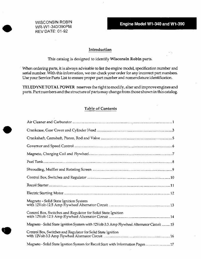
WISCONSIN ROBIN WR-WI -340/390PM REV DATE: 01-92
Introduction . ..
This catalog is designed to identify Wisconsin Robin parts.
When ordering parts, it is always advisable to list the engine model, specification number and serial number. With this information, we can check your order for any incorrect part numbers. Use your Service Parts List to ensure proper part number and nomenclature identification.
TELEDYNETOTAL POWER reserves the right to modify, alter and improve engines and parts. Part numbers and the structure of parts may change from those shown in this catalog.
Table of Contents
Air Cleaner and Carburetor ............................................................................................................. 1
Crankcase, Gear Cover and Cylinder Head ............................ ...................................................... 3
Crankshaft, Camshaft, Piston, Rod and Valve .............................................................................. 5
Governor and Speed Control ........................................................................................................... 6
Magneto, Charging Coil and Flywheel ........................................................................................... 7
Fuel Tank ............................................................................................................................................. 8
Shrouding, Muffler and Rotating Screen .. .. .. .. .. ... . . .. .. .... ..... . . .. . . ... .... .. .... . .... .. .. .. ..... .. .... .. .............,.. 9
Control Box, Switches and Regulator ........................................................................... ..... ........... 10
Recoil Starter ..................................................................................................................................... 11
Electric Starting Motor .................................................................................................................... ~2
Magneto - Solid State Ignition System with 12Volt-12.5 Amp Flywheel Alternator Circuit ................................................................... 13
Control Box, Switches and Regulator for Solid State Ignition with 12Volt-12.5 Amp Flywheel Alternator Circuit ................................................................... 14
Magneto -Solid State Igrution System with 12Volt-3.3 A m p Flywheel Alternator Circuit ......... 15
Control Box, Switches and Regulator for Solid State Igrution with 12Volt-3.3 Amp Flywheel Alternator Circuit ......................................................................... 16
Magneto - Solid State Ignition System for Recoil Start with Information Pages ........................... 17
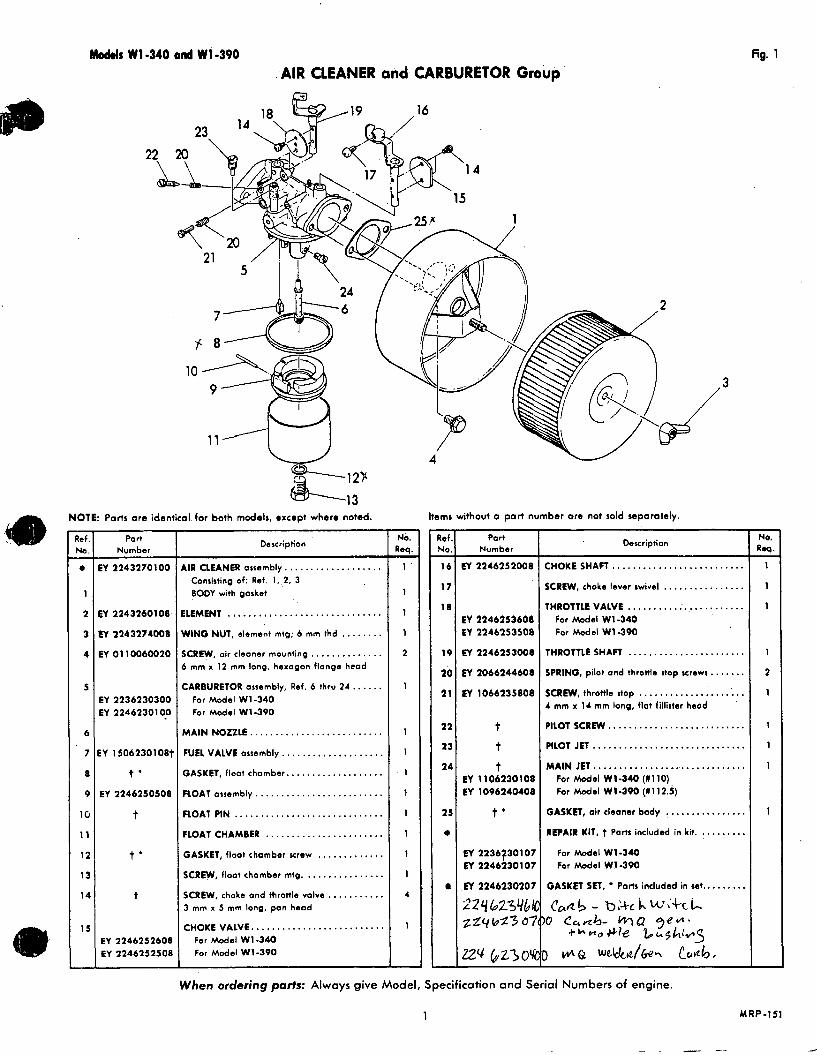
Models W1-340 a d W1-390 .AIR CLEANER and. CARBURETOR Group
- ?ef No.
e -
1
2
3
4
5
6
7
8
9
l G
11
11
13
14
1 5
-
NOTE: Ports are identicol. far both models, except where noted.
rl __
Po r l Number
EY 2243270100
EY 2243260108
Ey 2243274008
EY 0 1 1 OO6OO20
EY 2236230300 EY 22462301 00
EY 1506230108t
t ' EY 2246250508
t
t '
t
EY 2246252608 CY 1246252508
Description
AIR CLEANER assembly.. . . . . . . . . . . . . . . . . . Consisting of: Ref. 1,.2, 3 BODY with Oasket
ELEMENT .............................. WING NUT, element mtg; 6 mm thd . . . . . . . . SCREW, air cleaner mounting.. . . . . . . . . . . . . 6 mm x 12 mm long, hexogon flange head
CARBURETOR assembly, Ref. 6 thru 2 4 . , . . . . For Model W1-340 For Model W1-390
MAIN NOZZLE .......................... FUEL VALVE assembly.. . . . . . . , . . . . . . . . . . . GASKET, floot chomber.. . . . . . . . . . . . . . . . . . FlOAT assembly . . . . . . . . . . . . . . . . . . . . . . . . . FlOAT PIN . . . . . . . . . . . . . . . . . . . . . . . . . . . . . FLOAT CHAMBER . . . . . . . . . . . . . . . . . . . . . . . GASKET, floot chamber screw . . . . . . . . . . . . . SCREW, float chamber mtg. . . . . . . . . . . . . . . . SCREW, choke and throttle valve.. . . . . . . . .. 3 mm x 5 mm long, pan head
CHOKE VALVE.. , . . . . . . . . . . . . . . . . . . . . . . . For Model W1-340 For Model W1-390
- No. Req.
1 -
1
1
1
2
1
1
1
1
1
1
1
1
1
4
1
Items without a part number ore not sold separately. - tef I
*(O.
16
17
18
-
19
20
21
22
23
24
25
e
Part Number
EY 2246252008
EY 2246253608 EY 2246253508
ET 2246253008
M 2066244608
M 106623580a
t t t
EY 11 06130108 EY 1096140408
t '
EY2236i230107 ET2246130107
M2246230207
224 623%1( zZqkd3 67
ZZq 6230'4
Description
CHOKE SHAFT . . . . . . . . . . . . . . . . . . . . . . . . . . SCREW, choke lever swivel . . . . . . . . . . . . . . . . THROTTLE VALVE . . . . . . . . . . :. . . . . . . . . ,. .
For Model W1-340 For Model W1-390
THROTTLE SHAFT . . . . , . . . . . . . . . . . . . . . . . . SPRING, pilot and throftle stop screws,. . . . . . SCREW, throttle stop . . . . . . . . . . . . . . . . . ... . . 4 mm x 1 1 mm long, flat fillister head '
PILOT SCREW.. . . . . . . . . . . . . . . . . . . . . . . . . . PILOT J E T . . ............................ MAIN JET. .............................
For Model W1-340 (#110) For Model W1-390 (1112.5)
GASKET, air cleaner body !. . . . . . .. . . . . .. . REPAIR KIT, t Ports included in kit. . . . . . . . . .
For Model W1-340 For Model W1-390
GASKET SET, Parts included in set.. . . . . . . . Can6 - b;-+ck W ; k k
+ b ~ o # l e %h$h;g_Sj 10 Car~b- WQ f 3 4 M *
) 1N\Q w&kvtl&* &.4@b, When ordering parts: Always give Model, Specification and Serial Numbers of engine.
1
"
fig. 1
- NQ. 3
1
1
1
1
2
1
1
1
1
1
-
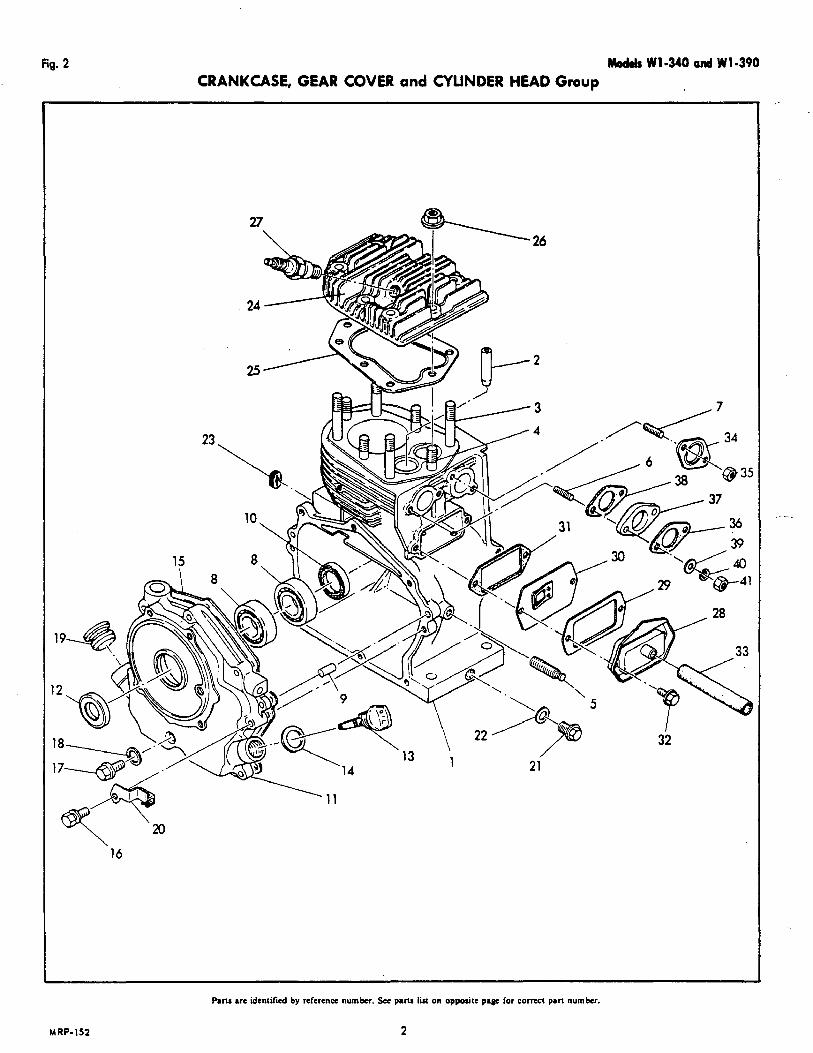
fig. 2 Mod& W1-340 and W1-390 CRANKCASE, GEAR COVER and CYLINDER HEAD Group
16
MRP-152
Pam arc identilied by reference number. Sec pans liu on opposife paw for c o m a pan number.
2

Modal$ W1-340 and W1-390 CRANKCASE, GEAR COVER and CYLINDER HEAD Group
NOTE: Ports are identical for both models, except where noted.
kems without o port number ore not sold repomtely. - kef. 40.
1 -
2
3
4
5
6
7
0
V
10
1 1
12
13
14
15
16
17
18
19
20
21
21
23
24
Part Number
W 224 1420203
W 010S100280
X 0105l00270
X 0105080031
3 00:3106351
EY OOl3l08301
EY 0600350010
EY 0052608180
EY 0440350090
EY 22411 10101
W 2246360107
MOOl l408350
€Y 011OO6OOlO
EY oo~7oo6ooa
EY 2244420101
EY 040114003a
EY 021 I 1 4 0 0 1 ~
€Y 2247550103
EY 2231300103 M 224133040!
Description
LYLINDER - CRANKCASE. . . . . . . . . . . . . . , . . IALVEOUIDE .......................... iTUD, cylinder head mounting . . . . . . . . . . . . . 0 mm x 87 mm long.
ITUD, cylinder hood mounting . . . . . . . . . . . . . 0 mm x 54 mm long.
ITUD, governor control mounting . . . . . . , . . . . JUD, corburetor mounting.. . . . . . . . . . . . . . . I mm x 35 mm long.
iTUD, muffler mounting . . . . . . . . . . . . . . . . . . I mm x 30 mm long.
IEARING, cronkshoft main.. . . ........, .. . )OWEL PIN, geor cover . . . . . . . . . . . . . . . . . . 311 H A L , crankcase.. . . . . . . . . . . . . . . . . . . . . 3EAR COVER assembly.. . . . . . . . . . . . . . . . . . EY 0440350090 011 SEAL . . . . . . . . . . . . . . . Dl1 DIP STICK . *. .. . . . . a * . . . * . . . . . * . . . . . EY 02132000lO GASKET . . . . . , . . . . . . . . , , .
Includes: bo r ing (Ref. 8)
Includes:
GASKET, geor cover . . . . . . . , . . . . . . . . . . . . . z 2 4 I S L 0 I 03
SCREW - WASHER, geor cover mounting . . . . 8 mm x 35 mm long, hexagon head
ICREW, baloncer gear ossembly . . . . . . . . . . . b mm x 8 mm long, hexagon flange head
GASKET, balancer geor ossemb. screw . . . . . I
PLUG, oil filler . . . . . . . . . . . . . . . . . . . . . . . . . . BRACKET, remote speed control.. . . . . . . . . . 011 DRAIN PLUG, (less gasket). . . . . . . . . . . . . GASKET, oil drain plug (order sop.) . ...,.., GROMMET, ignition wire.. . . . . . . . . . . . . . . . I CYLINDER. HEAD . . . . . . . . . . . . . . . . . . . . . . .
For Model W1-340 For Model WI-390
- Ho.
kL
2
4
4
1
2
2
2
2
1
1
1
1
1
8
1
1
1
1
2
2
1
1
'Included in Engine Gasket Set, (Ref. 4, Pogo 5) . - Ref
No. 25
26
27
28
29
30
31
32
33
34
35
34
3?
36
39
4a
41
Pad Number .
!Y 2231510103 X2241510103
!Y 002381 OOOO
Y 06!50140036
EY 66M1401VO
PI 2241430101 . X 2241U0101
W 01 !OO6OO30
W 085l12OO10
Y 2243510103'
EY 0021908000
* EY 2243S20103
ET 2243290103
EY 003 1006000
EY 0032006000
EY 0022706000
Illust. Fig. 2
Description
iASKET, cylinder head . . . . . . . . . . . . . . . . . . . For Model W1-340 For Model W1-300
JUT, cylinder head mounting.. . . . . . .. . . .. . 0 mm, hexagon flonge type
;PARK PLUG with gasket (Standard 1 . . . . . . . :hornpion 186. AC U F , NGK UHS.
;PARK PLUG,forS.S.Ignitlon,NGK BP-4HS
:OVER, tappet inspection.. . . . . . . . . . . . . . . . U S K E T , inspection cover . . . . . . . . . . . . . . . . . IRCATHER P U T E assembly.. . . . . . . . . . . . . . . SASKET, breather plote . . . . . . . . . . . . . . . . . . ICREW, inspection cover . . . . . . . . . . ,. . . . . . , 1 mm x 14 mm long, hexagon flonge hood
IREATHER TUBE . . . . . . . . . . . .. . . . . . . . . . . . SASKET, muffler mounting . . . . . . . . . .. . . . . . JUT, muffler mounting . . . . . . . . . . . . . . . . .. . I mm threod, henogon steel
USKET, carburetor flonge (paper). . . . . . . NSUIATOR, carburetor flange.. . . . . . . . . . . . 3ASKET, insulator to block (composition). . . . . MASHER, corburetor mounting.. . . . . . . . . . . . b.4 mm I.D. x 11. 5 O.D., plain steel
.OCKWASHER, corburetor mounting . . . . . . . . 5 mm spring lock
UUT, carburetor mounting.. . . . . . . . . . . . . . . . 5 mm threod, hexogon (teal
No. Req. -
1
8
1
1
1
1
1
2
1
1
2
1
1
1
2
2
2
-
When ordering ports: Always give Model, Specification and Serial Numbers of engine.
MRP.1591
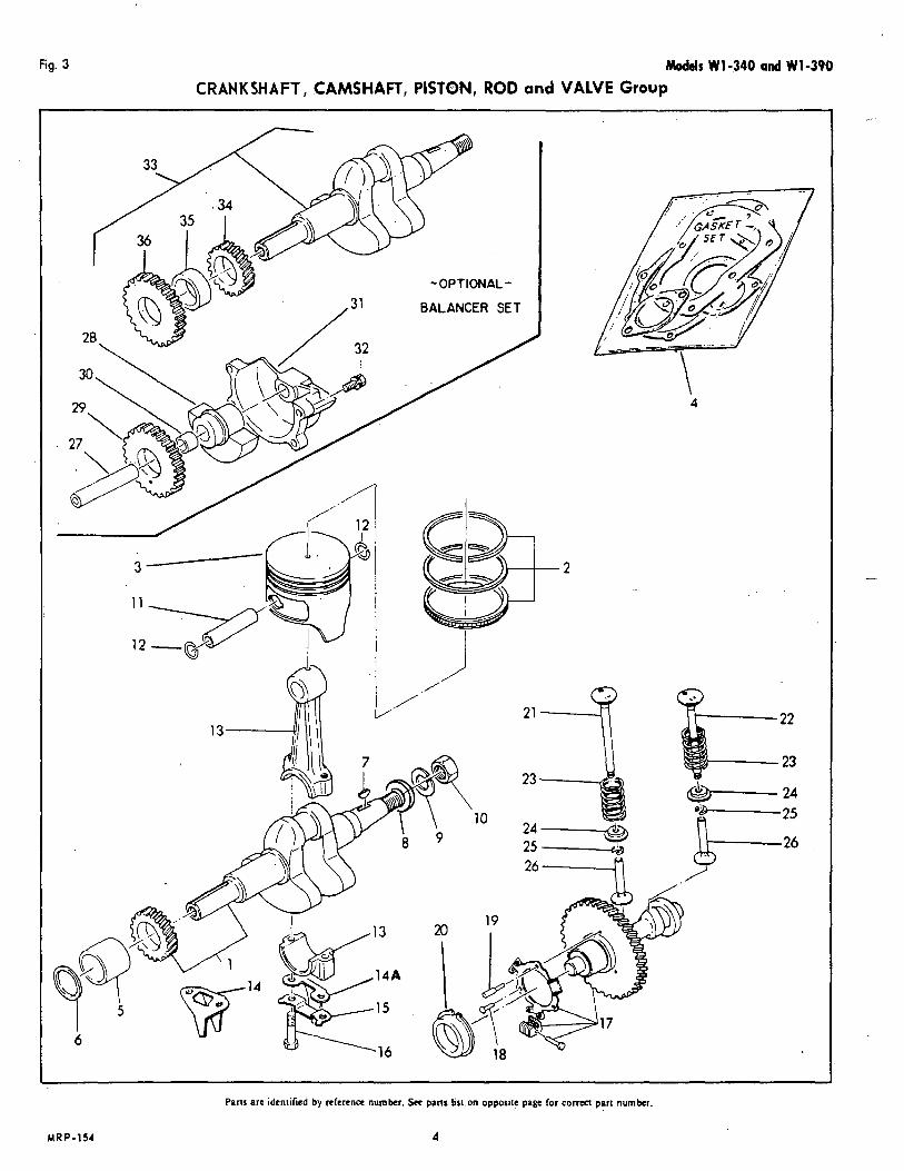
fig. 3 M o d e l s W1-340 and W1-390 CRANKSHAFT, CAMSHAFT, PISTON, ROD and VALVE Group
2
4
MRP-154
Pans are identified by reference number. See pans Lirt.on opposite page for c o r m part numkr.
4
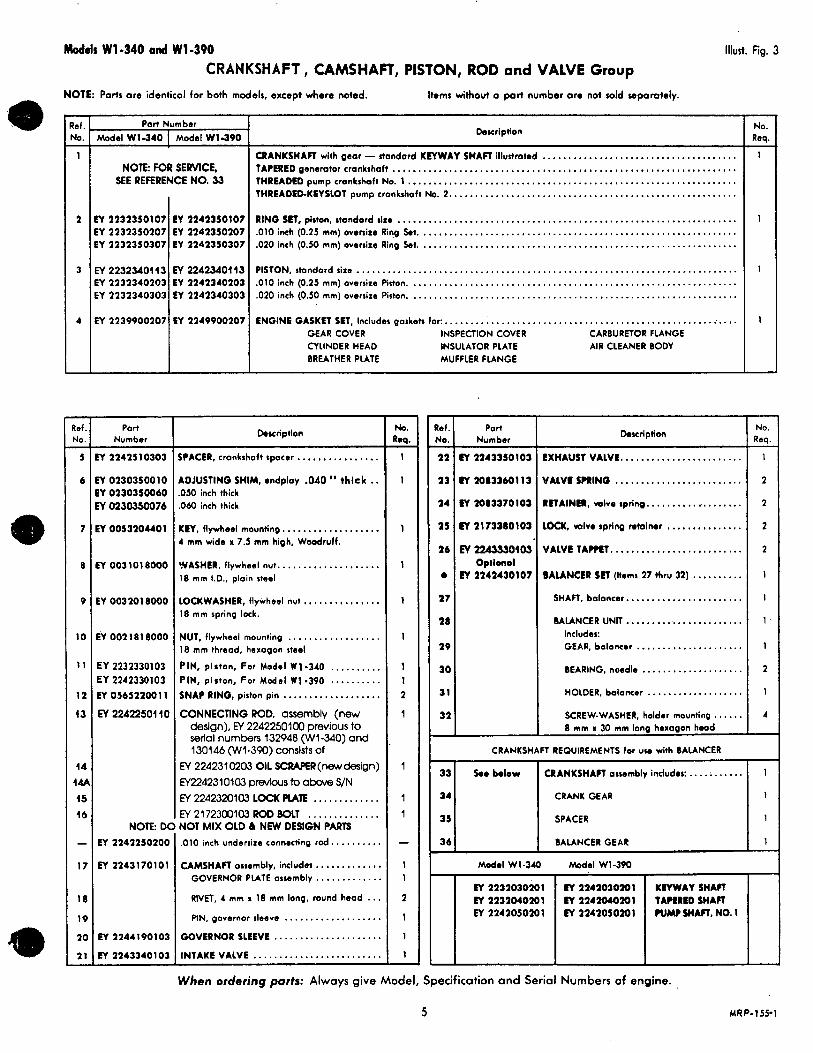
Models W1-340 and W1-390 Illud. Fig. 3 CRANKSHAFT CAMSHAFT, PISTON, ROD and VALVE Group
6
7
8
9
10
1 1
12
i 3
44 w 15 46
- 17
18
19
2a
21 -
Par, Number Model W1-340 [ Model W1-390
NOTE: FOR SERVICE, SEE REFERENCE NO. 33
EY2232350107 EY 2242350107 EY2232350207 EY 2242350207 EY2232350307 EY 2242350307
EY 22323404 13 M 2242340443 EY 2232340203 EY 2242340203 EY2232340303 EY 2242340303
EY 2239900207 EY 2249900207
I
Port Number
!Y 224251 0303
EY 0130350010 EY 0230350060 Y 02303sO76
WOO53204401
EY0031018000
EY 0032018000
EY 002 18 1 8000
EY 2232330103 EY 2242330103 EY 056522001 1
N O E DC EY 2242250200
EY 2243170101
EY2244190103
€Y1243340103
Description
CRANKSHAFT with gear - standard KEYWAY SHAFl illustrated ...................................... TAPERED generator crankshaft ................................................................... THREADED pump cmnkchoft No. 1 ................................................................ THREADEPKEYSLOT pump crankshaft No. 2.. ...................................................... RlNQ SET, piston, standard size .................................................................. .010 inch (0.25 mm) ovenixe Ring Set. ............................................................. .020 inch (0.50 mm) oversize Ring k t . ............................................................. PISTON,standardsire .......................................................................... .010inch(0.25 mm)oversire Piston. ............................................................... .020 inch (0.50 mm) oversixe Piston. ............................................................... ENGINE GASKET SET, Includes gaskets for:, .........................................................
GEAR COVER INSPECTION COVER CARBURETOR FLANGE CYLINDER HEAD INSULATOR PLATE AIR CLEANER BODY BREATHER PLATE MUFFLER FLANGE
Description
SPACER, crankshaft spacer.. .............. ADJUSTING SHIM, endplay .040 " thick . . ,050 inch thick ,060 inch thick
KEY, flywheel mounting.. ................. 4 mm wide x 7.5 mm high, Woodruff.
WASHER, flywheel nut.. .................. 18 mm I.D., plain steel
LOCKWASHER, flywheel nut ............... 18 mm spring lock.
NUT, flywheel mounting .................. 18 mm thread, hexagon steel
PIN, piston, For Model W1-340 .......... PIN, piston, For Model W1-390 .......... SNAP RING, piston pin ................... CONNECTING ROD, assembly (new
deslgn), N 22422501 00 previous to serlal numbers 132948 (WI-340) and
N 2242310203 OIL SCRAF€R(newdeslgn) Ff2242310103 PWS to above S/N EY 2242320103 L O C K PLATE ............. EY 2172300103 ROD BOLT .............. NOT MIX OLD & NEW DESIGN PARTS
130146 (Wl-390) Consists of
,010 inch undersize connecting r o d . . ........ CAMSHAFT assembly, includes .............
GOVERNOR PLATE assembly ............. RIVET, 4 mm x 18 mm long, round head . I . PIN,~overnorsieeve ...................
GOVERNOR SLEEVE ..................... INTAKE VALVE .........................
- No. Req.
1
1
1
1
1
1
1 1 2
1
1
1 1
- 1 1
2
1
1
1 -
- tef. YO.
22
23
24
1 s
26
-
e
27
20
29
3a
31
31
-
Part Number
Doscription
CY 2243350103 EXHAUST VALVE.. ...................... EY 20833601 13 WALVC SHIN0 ......................... EY 2083370103 RETAINER, w ive spring.. ........ ,. ....... CY 2173360103 L O C K , valve spring retainor ............... EY 2263350103 VALVE T A M T . . ........................
Optional EY 2242430107 BALANCER SET (Items 27 thru 32) ..........
SHAFT, balancer.. ..................... BALANCER UNIT.. .....................
Includes: GEAR, boloncw ..................... BEARING. noodle .................... HOLDER, boloncer ................... SCREW-WASHER, holder mounting ...... 8 mm x 30 mm long hexagon head
CRANKSHAFT REQUIREMENTS for u w with BALANCER
- No. Req.
1
1
1
1
-
- No. Req.
1 -
1
1
1 '
1
2
1
4
.......... CRANK GEAR
SPACER
Model W1-340 Model W1-390
When ordering parts: Always give Model, Specification and Serial Numbers of engine.
5 MRP-155- 1
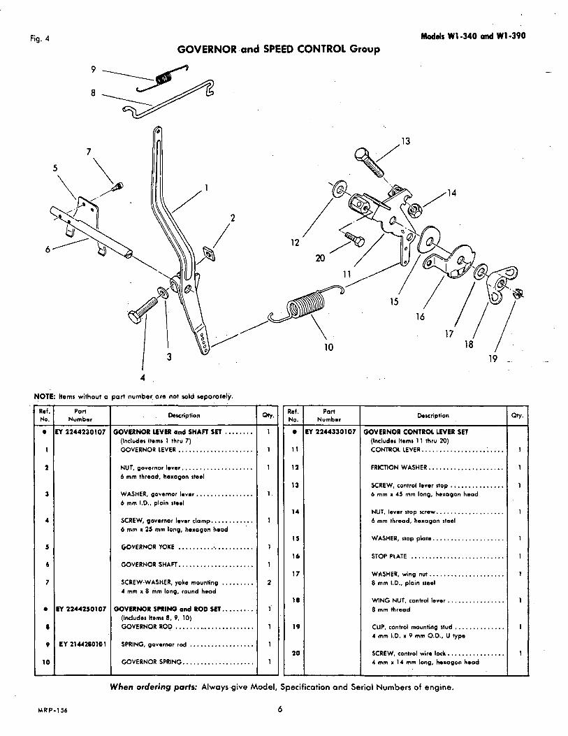
Fig. 4 Models W 1 -340 and W 1-390 GOVERNOR and SPEED CONTROL Group
4
NOTE: Items without a part number, ore not sold separately. - Ref. No. e -
1
2
3
4
5
6
7
e
I
9
10
-
Part Number
Y 2244230107
Y 2244250107
EY 21U280101
. . Description
iOVERNOR LEVER ond SHAFT SET ........ (Includes Items 1 thru 7 ) GOVERNOR LEVER., ................... NUT, governor lover.. ................... 6 mm thread. hexagon steel
WASHER, governor Ievor.. .............. 6 mm 1.0.. ploin rtoel
SCREW, govornor lover clamp.. .......... 6 mm X 25 mm long, hoxogon hood '
GOVERNOR YOKE ...................... GOVERNOR SHAFT.. ................... SCREW-WASHER, yoke mounting . , , . , , . , , 4 mm x 8 mm long. round hood
3OVERNOR SPRING ond ROD SET.. ....... (Includes Rems 8, 9, 10) GOVERNOR ROD ....................... SPRING, governor rod .................. GOVERNOR SPRING.. ..................
- Qtv. -
1
1
1
1 .
1
1
1
2
1'
1
1
1
-
- Ref. No. -
11
12
13
14
15
16
17
18
19
20
\ 10 l 8 /
Port Number
Y 2244330107
Description
iOVERNOR CONTROL EVER SET (Includes ltems 1 1 thru 20) CONTROL LEVER.. ............... .: .... FRICTION WASHER.. ................... SCREW, control lever stop ............... 6 mm K 45 mm long, hexagon head
NUT, lever stop screw.. ................. 6 mm thread. hexagon steel
WASHER, stop plate.. .................. STOP PLATE .......................... WASHER, wing nut ..................... 8 mm I.D., plain steel
WING NUT, control lever.. .............. 8 mm threod
CLIP, control mounting stud .............. 4 mm 1.D. I 9 mm O.D., U type
SCREW, control wire lock.. .............. 4 mm x 14 mm long, hexagon head
- w. -
1
1
1
1
1
1
1
1
1
1
- When ordering ports: Always give Model, Specification and Serial Numbers of engine.
MRP-156 6

Mod& Wl-340 and W1.490 MAGNETO - CHARGING COIL and FLYWHEEL Group
Fig. 5
A i NOTE hems without o port number are not sold separotely. - Ref. No.
1 -
2
3
a
4
5
5
7
0
e
Q
IO -
Part Number
Y 2247011100
EY 2247010407
EY 2247013208
EY 2247010107
M 1147010307
Description
FLYWHEEL, standard. Manual Stort.. ....... FLYWHEEL assembly. Electric Stati .......... EY 2247100203 RING GEAR ..............
Ihcludes:
IGNITION COIL, standord. Manual Start and Electric Start ...................... POINTS and CONDENSER KIT .............
Consisting of: CONDENSER .................... .:. .. CONTACT BREAKER ..................... LEAD WIRES .......................... NUT, Iwd wire.. ....................... LOCKWASHER, lead wire.. . . ............
COVER - HARDWARE KIT, for points and . . condenser mounting ' Consisting of: Ref. 9 thru 14
BREAKER COVER. ........................
O I L FELT, breoker ......................
- Ref. No.
1 1 -
12
13
14
111
14
17
l e
I F
2c
-
Part Number
M0043506250
ET 0655000050
EY1147014400
MOO43504300
M 0241090050
M 21470l7000
\ 17
hwr ipt ion
SCREW-WASHER, breoker mounting.. ..... 4 mm x 8 mm long, pon heod
SCREW-WASHER, cover mounting.. ....... 4 mm x 12 mm long, pan heod
SCREW, condenser mounting.. ........... 3 mm x 6 mm long, round hood
LOCKWASHER, condenser mounting ....... 3 mm, spring lock
SCREW-WASHER, ignition coil mtg. .......... b mm x 25 mm long, round head
CAP, spark plug terminol . . . . . . . . . . . . CHARGE COIL with cable .................
For Electric Stort engines
SCREW-WASHER assembly, chorge coil, ..... 6 mm x 30 mm long, pan heod
GROMMET, spark plug cable.. ............ LEAKAGE PASS, ignition coil.. .............
For electric start engines
When ordering parts: Always give.Model, Specification and Serial Numbers of engine.
2
1
1
2
2
7 MRP-157-1
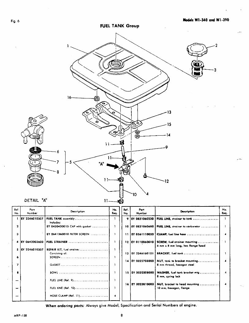
Fig. 6 Moddr W1-340 and W1-396 FUEL TANK Group
".
- 15
-14
- 5
DETAIL "A" 1 1 4
Ref. I Port No. Number
1 IEY 2246010207
2
3
4 EY 0642003600
Description
FUEL TANK orsembly.. . . . . . . . . . . . . . . . . . . . Includes:
EY 043043W 15 CAP with gorket . . . . . . . . . .
EY 0641360010 FILTER SCREEN . . . . . . . . . . . FUELSTRAINER ......................... REPAIR KIT, fuel slroiner.. . . . . . . . . . . . . . . . .
Consisting of:
SCREEN ..............................
GASKET ..............................
BOWL ............................... FUEL LINE (Ref. 9 ) . . . . . . . . , . . . . . . . . . . . , . FUEL LINE (Ref. 10). . . . . . . . . . . . . . . . . . . . . HOSE CLAMP (Ref. 1 1 ) . . . . . .. . . , , . . . . . . .
- No. Req.
1 -
1
1
1
1
1
1
1
1
1
4 -
- 1.1. .40.
9 -
1 0.
1 1
12
13
14
15
16
Port Number
EY 0851060230
EY 0851060680
EY 0561 1 1 0010
EY 0110060010
EY 2246160101
EY 0022708000
EY 0032008000
EY OO238lOOOO
Omscription
FUEL UNE, strainer to tank . . , . . . . . . . . . . . . . FUEL UNE, rtroiner ?o corburetot . . . . . . . . . . . CLAMP, fuel line hose . . . . . . . . . . . . . . . . . . . . SCREW, fuel strainer mounting . . . . . . . . . . . . . 6 mm x 8 mm long, hex flange b a d
BRACKET, fuel tank.. . . . . . . . . . . . . . . . . . . . . NUT, tank to brockot mounting.. . . . . . . . . . . . 8 mm thread, hexogon sted
WASHER, fuol tank brock.( mtg.. . , . . . . . . . . 8 mm, spring lock
NUT, brocket to head mounting . . , , , , , . , . . . 10 mm, heragon, flange
- NO. Req.
4
1
1
4
4
4
When ordering parts: Always give Model, Specification and Serial Numbers of engine.
MRP-158 8
Mod& W1-340 and W1-390
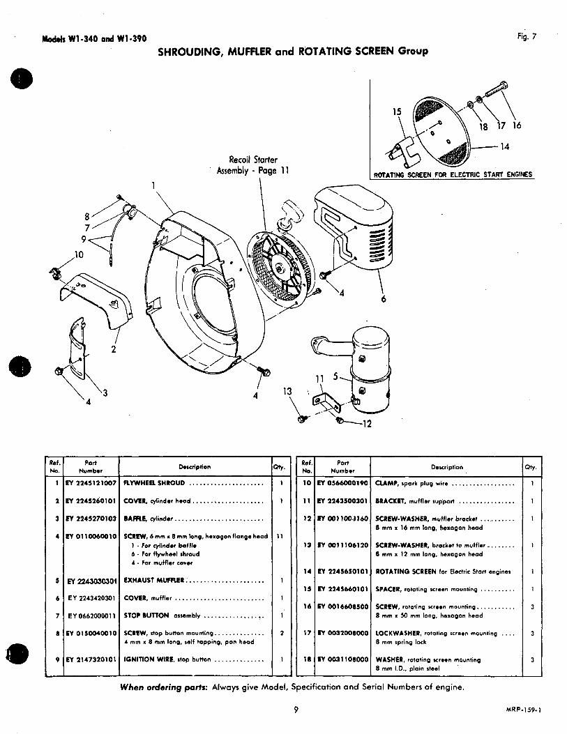
SHROUDING, MUFFLER and ROTATING SCREEN Group Fig. 7
Recoil Starter Assembly - Page 11 RaTATIflNo SCREEN FOR ELECTRIC START ENGINES
I
\ '3 '4
Porr Number
Y 2245121007
Y 2245260101
PI 2245270103
w o11moo1a
M 224303030!
EY 2243420301
EY 066200001 1
EY o1soo4oo1a
EY 2147320101
4
~
Description ~
FLYWHEEL SHROUD ..................... COVER, cyiinder hood.. .................. BAFRE, cylinder ......................... SCREW, 6 mm a 8 mm long, hexagon flange hood
1 - For cylinder baffle 6. For flywheel shroud 4 - For muffler Cover
EXHAUST MIJFR.€R : ..................... COVER, muffler ......................... STOP BUTTON assembly ................. SCREW, stop button mounting.. ............ 4 mm 'x 8 mm long. self topping. pan head
IGNITION WIRE, step button ..............
Ref.1 Port No. Number I Description
10 EY OS660001~0 CUMP, spark plug wire .................. 11 EY 2243500301 BRACKET, muffler suppod ................ 12 EY 001 1001160 SCREW-WASHER, muffler bracket ...........
0 mm x 16 mm long, hsxogon hood
13 EY 0 0 ) 1106120 SCREW-WASHER, brocket to muffler.. ...... 8 mm x 12 mm long, heaogon head
14 EY 1245650101, ROTATING SCREEN for Electric Stort engines
15 EY 2245660101 SPACER, rotating screen mounting .......... 16 EY 0016608500 SCRIW, rototing ween mounting.. .........
8 mm x 50 mm long, hexogon head
17 EY 0032008000 LOCKWASHER, rototing screen mounting .... E mm spring lock
18 EY 0031 108000 WASHER, rotating xreen mounting 8 mm I.D., ploin steel
When ordering p a r t s : Always give Model, Specification and Serial Numbers of engine.
1
1
I
3
3
-
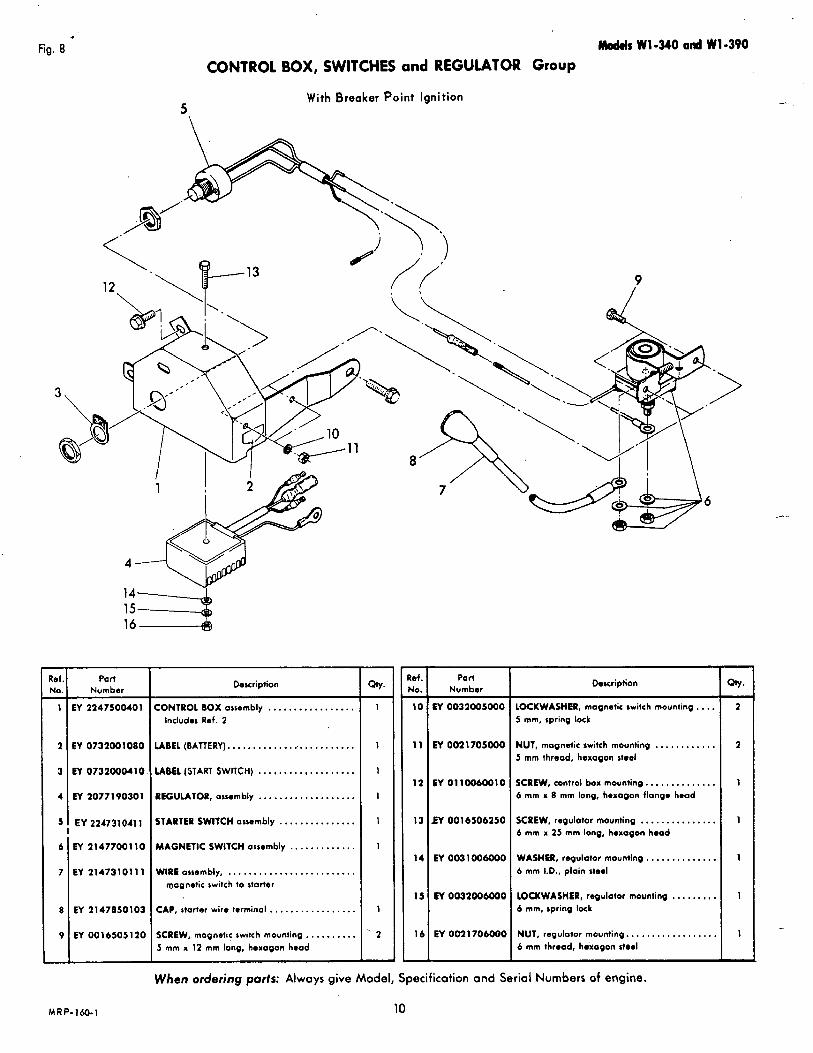
Fig. 8 Modds W1-340 and vY1-390
CONTROL BOX, SWITCHES and REGULATOR Group
5 . With Breaker Point Ignition
9
4
14 15
Part Number
EY 2247500401
EY 0732001080
EY 0732OOO4 10
EY 2077190301
EY 224731041 1
EY 21477001 10
EY 214731011 1
EY 2147850103
EY 001 6505 120
MRP-160-1
Description
CONTROL BOX assembly ................. Includes Ref. 2
LABEL (BATTERY). ......................... LABEL (START SWITCH) ................... REGULATOR, assembly ................... STARTER SWITCH orsembly ............... MAGNETIC SWITCH assembly ............. WIRE osrembly, .........................
mognetic switch to starter
CAP, storter wire terminal ................. SCREW, magnetic switch mounting .......... 5 mm x 12 mm long, hoxagon hoad
- ?et. No. 10 -
1 1
11
13
14
15
16
-
Part Number
EY 0032005000
EY 002 1705000
EY 0110060010
EY 0016506250
EY 0011006000
ET 0032006000
EY 0021 706000
Doacription
LOCKWASHER, magnetic switch mounting.. , . 5 mm, spring lock
NUT, magnetic switch mounting ............ 5 mm thread, hexagon stoel
SCREW, control box mauntino.. ............ 6 mm x 8 mm long, hexagon flange hood
SCREW, regulotor mounting ............... 6 mm x 25 rnrn long, hoxagon hoad
WASHER, regulator mounting .............. 6 mm 1.0.. plain rteol
LOCKWASHER, regulator mounting . . , . . , , . . 6 mm, spring lock
NUT, regulotor mounting.. ................ 6 mm thread, hwagon steel
When ordering parts: Always give Model, Specification and Serial Numbers of engine.
10
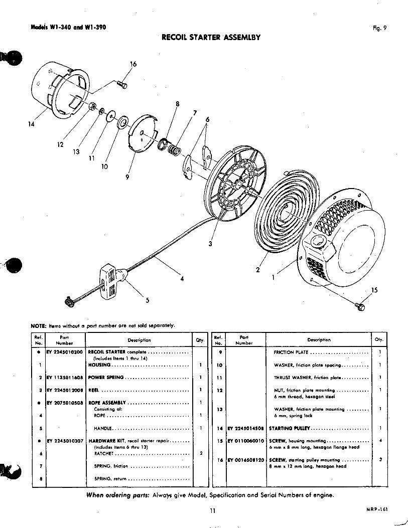
Modr js W1-340 a d W1-390 'fig. 9
RECOIL STARTER ASSEMLBY
I 3
2
NOTE: Items without o port number ore not d d mporotely. '"" Number
0 N 2245010200 I 2 EY 1135011608
3 EY 2245012008
0 N 2075010508
4
5
0 Cy 224501 0307
6
7
8
Description
RECOIL STARTER complete ................ HOUSING ..............................
(Ixludes Items 1 thru 14)
POWER SPRING.... . . . . . . . . . . . . . . . . . . . . .
REEL .................................. R O P E A S S t M B L Y . . . . . . . . . . . . . . . . . . . . . . . .
Consisting of: ROPE ................................ HANDLE.. ............................
HARDWARE KIT, recoil s?arter repoir.. ...... (Includes Items 6 thru 13) RATCHET............ ................. SPRING, friction ....................... SPRING, return ........................
- Ref. No.
V -
10
11
12
13
14
15
16
~
Par, Number
!Y 2245014501
!Y 01 10060010
W 001 6508 I20
~
Description
FRICTION PLATE ....................... WASHER, friction plote spacing.. ......... THRUST WASHER, friction plate.. ......... NUT, friction plate mouncing ............. 6 mm threod. hexagon s t d
WASHER, friction plate mounting ......... 6 mm, spring lock
STARTINQWU EY ............... :....... SCRW,housing mounting ................. 6 mm x 8 mm long. hexagon flange hood
SCREW, starting pulley mounting ........... 8 mm x 12 mm long, hexagon h w d
When ordering parts: A l w a y give Model, Specification and Serial Numbers of engine.
1
1
1
1
1
1
4
3
-
11 MRP-161
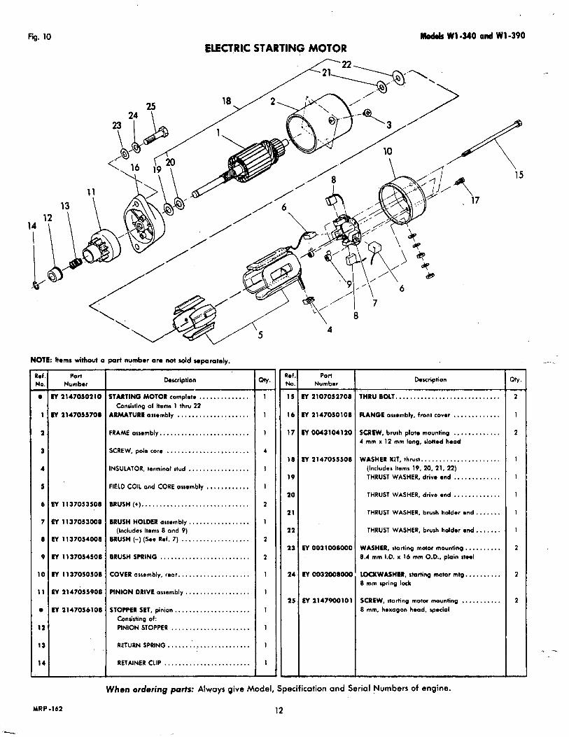
Fig. 10 ELECTRIC STARTING MOTOR
Mokb W1440 and Wl -390
NOTE: k m r without o part numbor or0 not d d wporotely. 7
Ref NO.
e -
1
2
3
4
5
6
7
8
9
IO
11
e
la
13
14 -
Part Number
iY 2147050210
fY 2147055708
N 1137053508
EY 1137053008
W 1137054008
W 1137054508
tV 1137050508
N 2147055908
tV 2147056108
Douription
STARTING MOTOR complete . . . . . . . . . . . . . . ARMATURE assembly . . . . . . . . . . . . . . . . I . . . FRAME assembly.. . . . . . . . . . . ,. . , . . . . . . . . . SCREW, pole core . . . . . . . . . . . . . . . , . . . . . . , INSULATOR, terminal stud . . . , . . . . . . . . . . . . . FIELD COIL and CORE ossembly . . , , . . . . , . , . BRUSH (+). . . . . . . . . , . . . . . . . . . . . . . . . . . . . . BRUSH HOLDER ossembly . . . . . . . . . . . . . . . . .
Consisting of ltema 1 thru 22
(Includes Items 8 and 9) BRUSH (-) ( h e Rei. 7) . . . . . . . . . . . . . . . . . . . BRUSHSPRING ......................... COVER ossembly, rear.. . . . . . . . . . . . . . . . . . . PINION DRIVE assembly . . . , . . . . . . . . , . . . . . STOPP€R SET, pinion.. , , . . . . . , . . . . . . . . . , .
Consisting of: PINION STOPPER . . . . . . . . . . . . . . . . . . . . . . RETURN SPRING.. . . . . . . . . . . . . . . . . . . . . . RETAINER CLIP . . . . . . . . . . . . , . . . . . . . . . . .
- w- -
1
1
1
4
1
1
2
1
2
2
1
1
1
1
1
1 -
- b f N o .
I5 -
16
17
18
19
20
21
22
23
1 4
25
4
Port Number
PI 2107052708
N 2147050108
EY0043104120
N 2147055508
ET 0031008000
M 0032WI000
N 2147900101
Doscription
THRU BOLT.. . . . . . . . . . , . . . . . . . . . . . . . . . . . RANGE auembly, front cover . . . . . . . . . . . . . SCREW, brush plat. mounting . . . . . . . . . . I . . 4 rnm x 12 mm long, Jotted head
WASHER KIT, thrust.. . . . , . . . . . , . . . . . . , . . . (Includes Items 19, 20, 21, 22) THRUST WASHER, drive end . . . . . . . . . . . . . THRUST WASHER, drive end . . . . . . . . . . . . . THRUST WASHER, brush holder end . . . . . . . THRUST WASHER, brush hddor end.. . . . . .
WASHER, starting motor mounting,. . , . . , . . . 8.4 mm I.D. x 16 mm O.D., plain Hool
LOCKW*SHER, starting motor mtg.. . . . . . . . . 8 mm spring loch
SCREW, Itoriing motor mounting .. . . . . . . . . . 8 mm, hexagon hood. spocia l
15
1
2
2
2
When ordering parts: Always give Model, Specification ond Serial Numbers of engine.
MRP-162
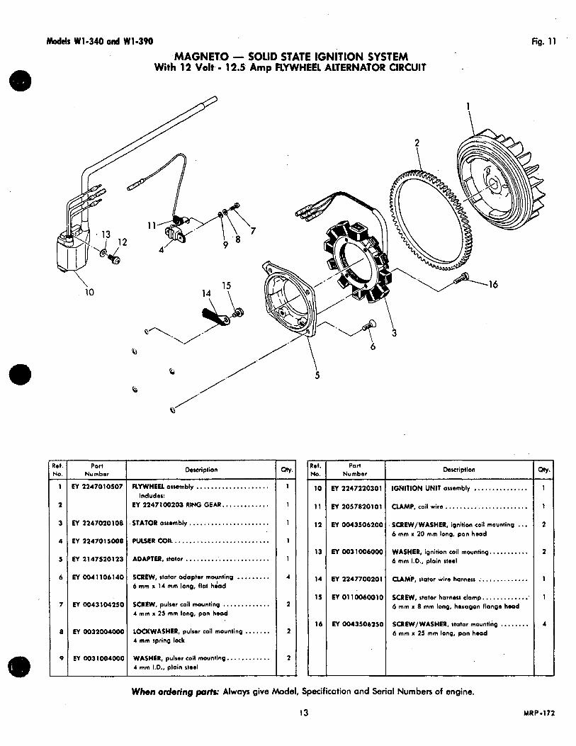
M I S W1-340 and W1-390 fig. 11
MAGNET.0 - SOLID STATE IGNITION SYSTEM With 12 Volt - 12.5 Amp RYWHEEL .ALTERNATOR CIRCUIT
- lef. 40.
1 -
2
3
4
5
6
7
8
9
-
\ i o
Port Number
EY 2247010507
M 2247020108
M 2247015008
M 2147520123
EY Oo41106140
EY 0043104250
ET 0032004OOC
EY 003100400c
15 14 \
FLYWHEEL assembly .................... EY 2247 100203 RING GEAR. ............ Includes:
STATOR osmmbly ...................... PULSLRCOlL... . . . . . .................. ADAPTER, atotor ....................... SCREW, stotor odaptor mounting ......... 6 mm x 14 mm long, flat hdod
SCREW, pulsar coil mounting ............. 4 mm x 25 mm l ong , pon head
LOCKWASHER, pulsar coil mounting ....... 4 mm spring lock
WASHER, pulser coil mounting.. .......... 4 mm 1.0.. ploin steel
” I 1
1
1
1
1
4
2
2
2
-
5
- et. 40.
10 -
11
12
13
14
15
16
-
- \ = 6
Numbar Description
EY 2247220301
CLAMP. coil w i r e . . ..................... 1 EY 2057820101
IGNITION UNIT assembly ............... 1
. SCREw/WASHER, ignition coil mounting ... 2 EY 0043506200 6 mm x 20 mm long, pon head
EY 0031006000 WASHER, ignition coil mounting.. ......... 2 6 mm I.D., ploin steel
EY 2247700201
SCREW, stator harness c lamp. . ............ 1 EY 01 10060010
CLAMP. stator wire harness .............. 1
6 mm x 8 mm long, hexagon f lange head
EY 0043506250 6 mm x 25 mm long, pon h.ad SCREW/WASHER, stator mounting ........ 4
When ordering pads Always give Model, Specification and Serial Numbers of engine.
13 MRP.172

Fig. 12 Models W1-340 and W1-390
CONTROL BOX, SWITCHES and REGULATOR Group For SOLID STATE IGNITION with 12 Volt - 12.5-Amp FLYWHEEL ALTERNATOR CIRCUIT
- lef. rl0.
1 -
2
3
4
5
6
7
8
9
10
11
-
Port Number
EY 2247510501
EY 073200 1080
EY 224731071 1
EY 0732000410
EY 2247260101
EY 0732000700
EY 2147700110
EY 21473101 11
EY 2147850103
EY 001 6505 120
EY 0032005000
MRP-I73
Description
CONTROL BOX ossembly . . . . . . . . . . . . . . . . (Includes Ref. 2)
LABEL (BATTERY) .......................
STARTER SWITCH assembly. . . . . . . . . . . . . .
LABEL (START SWITCH) . . . . . . . . . . . . . . . . . .
OFF/ON (CHARGE) SWITCH ossembly . . . . .
LABEL (OFF/ON SWITCH) . . . . . . . . . . . . . . . . MAGNETIC SWITCH assembly.. . . . . . . . . . . WIRE ossembly ........................ Magnetic switch to storting motor
CAP, storting motor terminal .............
SCREW, mognetic switch mounting ........ 5 mm x 12 mm long, hexagon head
LOCKWASHER, mognetic switch mounting . . 5 mm, spring lock
- QtY
1 -
1
I
1
1
1
1
1
1
- 2
2
- lef. r(0.
12 -
13
14
15
16
17
18
19
20
Y / /'
Number Part I Description
EY 0021705000 NUT, mognetic switch mounting.. ......... 5 mm threod, hexagon steel
EY 2247540101
BRACKET, control box (lower) ............ EY 2247540201
BRACKET, control boa (upper). ...........
EY 01 10060010 SCREW, control box brocket. ............. 6 mm x 8 mm long, hexagon flange heod
EY 0566120040 CLAMP, fuse support.. ..................
EY 01 10060010 SCREW, fuse clomp.. .................... 6 mm x 8 mm long, hex flonge hood
EY 2247610101 REGULATOR. current/voltoge ............
EY 0043506300 SCREW/ WASHER, regulotor mounting ..... 6 mm x 30 mm long, pon head
PI w q 2 i o o 7 FLYWHEEL smouo ....................
When ordering p a r t s : Always give Model, Specification and Serial Numbers of engine.
14
1
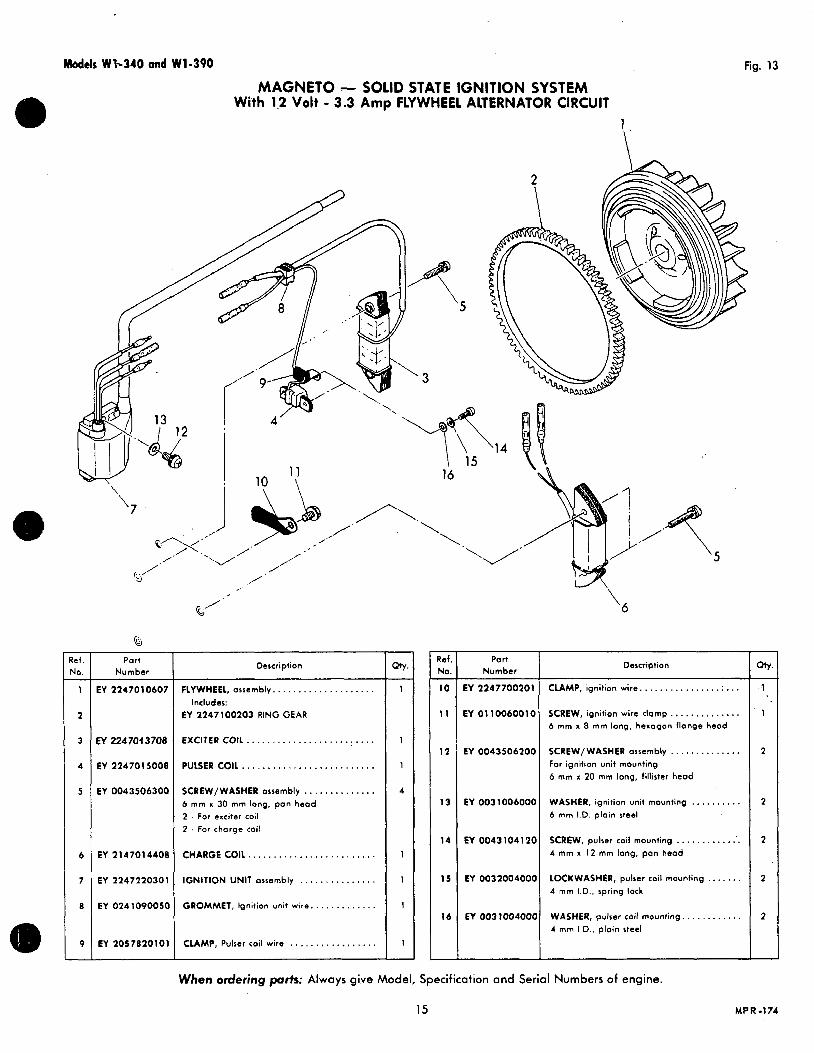
Models Wl-340 and W1-390
MAGNETO - SOLID STATE IGNITION SYSTEM With 1.2 Volt - 3.3 Amp FLYWHEEL ALTERNATOR CIRCUIT
Fig. 13
1
\
Part Number
EY 2247010607
w 2247owoa
EY 2247015008
EY 0043506300
EY 2147014408
EY 2247220301
EY 024 1090050
EY 2057820101
Description
FLYWHEEL, assembly.. . . . . . . . . . . . . . . . . . .
EY 2247100203 RING GEAR Includes:
EXCITER COIL.. .......................
PULSER COIL ..........................
SCREW/WASHER assembly . . . . . . . . . . . . . . 6 mm x 30 mm long, pan head 2 . For exciter coil 2 . For chorge coil
CHARGE COIL.. .......................
IGNITION UNIT assembly . . . . . . . . . . . . . . .
GROMMET, Ignition unit wire. . . . . . . . . .
CLAMP, Pulser coil wire . . . . . . . .
4
1 -
- Ref. No.
IO -
1 1
12
13
14
15
16
'6
Part Number
Description
EY 2247700201 CLAMP, ignition wire.. . ............ .:. ..
EY 0110060010 SCREW, ignition wire clamp., ............ 6 mm x 8 mm long. hexagon flange head
EY 0043506200 SCREW/WASHER assembly . . . . . . . . . . . . . . For ignition unit mounting 6 mm x 20 mm long, fillirtcr head
EY 0031006000 WASHER, ignition unit mounting .......... 6 rnm I.D. ploin steel
EY 0043104120 SCREW, pulser coil mounting .............. 4 m m a 12 mm long, pan head
EY 0032004000 LOCKWASHER. pulser coil mounting ....... 4 mm I.D.. spring lock
EY 003 1004000 WASHER, pulser coil mounting. . . . . . . . . . . . 4 mm I.D., plain steel
When ordering p a r t s : Always give Model, Specification and Serial Numbers of engine.
15 MPR-174
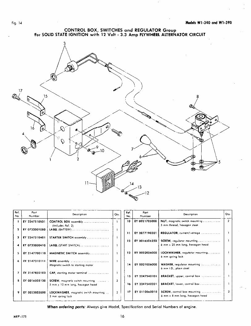
Fig. 14 Models W1-340 and W1-390
C O N T R O L BOX, SWITCHES and REGULATOR Group For SOLID STATE IGNITION with 12 Volt - 3.3 Amp FLYWHEEL ALTERNAYOR CIRCUIT
- !e(. 40.
1 -
2
3
4
5
6
7
8
9
-
Port Number
EY 2247510501
EY 0732001 080
EY 22473 1040 1
EY 0732000410
EY 2147700110
EY 214731011 1
EY 2147850103
EY 001 6505 120
EY 0032005000
Description
CONTROL BOX assembly . . . . . . . . . . . . . . . .
LABEL (BATTERY) .......................
STARTER SWITCH assembly. . . . . . . . . . . . . .
(Includes Ref. 2 )
LABEL (START SWITCH). . . . . . . . . . . . . . . . . .
MAGNETIC SWITCH assembly.. . . . . . . . . . .
WIRE assembly ........................ Magnetic switch to starting motor
CAP, starting motor terminol . . . . . . . . . . . . .
SCREW, mogneiic switch mounting . . . . . . . . 5 mm x 12 mm long, hexagon head
LOCKWASHER, magnetic switch mounting . . 5 rnm spring lock
- Ref. No.
10 -
1 1
12
13
14
1 s
16
17
Part Number
EY 002 1705000
EY 2077 19030 1
EY 0016506250
EY 0032006000
EY 003 1006000
EY 2247540101
EY 2247540201
EY 0110060010
Description
NUT, magnetic switch mounting 5 mm thread, hexagon steel
REGULATOR, curreni/voltage
SCREW, regulator mounting . . . . . . . 6 mm x 25 mm long, hexogan head
LOCKWASHER, regdator mounting. 6 mm spring lock
WASHER, regulator mounting . . . . . . . . . . . . 6 mm I.D., ploin steel
BRACKET, upper, control box . . . . . . . . . . . .
BRACKET, lower. control b o x . , . . . . . . . . . . .
SCREW, control box mounting . . . . . . . . . . . . 6 mm x 8 mm long, hexogon head
>ty.
2 -
1
1
When ordering parts: Always give Model, Specification and Serial Numbers of engine.
MRP-175 16
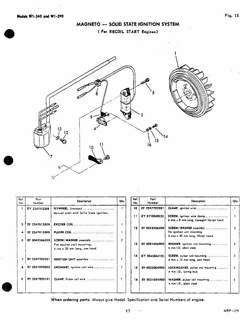
Mod& Wl-340 and W1-390 Fig. 15
"
Rei. NO.
1 -
7
8
9
'7
MAGNETO - SOLID STATE IGNITION SYSTEM ( For RECOIL START Engines)
1
Part Number
EY 2247012308
EY 224701 3508
EY z24701sooe
M 0043506300
EY 2147220301
EY 0241090050
EY 2057820101
Description
FLYWHEEL. Stondard .................... Manual start with Solid State Ignition.
EXUTER COIL.. ................
PULSER COIL .......................... SCREW/ WASHER ooembly .............. For exciter coi l mounting. 6 mm x 30 mm long, p a hood
IGNlTlON UNlT armmbly ...............
GROMMET, Ignition unit wire.. ...........
CLAMP. Pulser coil wire . ................ 1
- Ref N o . 10 -
1 1
12
13
14
15
16
\ \ '14 1s
16
Pon Number Description
EY 2247700201 QAMP, ignition wire. ...................
EY 0110060020 SCREW, ignition wire damp.. ............ 6 m m x 8 mm long, hwogan flacgr head
EY 0043506200 SCREW/WASHER orwmbly .............. For ignition unit mounting 6 mm x 20 mm long. lillirter head
ET 0031006000 WASHER, ignition unit mounting .......... 6 mm 1.0. plain steel
E Y 0043504120 S C R E W , puiser coil mounting ............. 4 mm x 12 mm long, pon hood
EY 0032004000 LOCKWASHER, pulsar coil mounting ....... 4 mm I.D., spring lock
EY 0031004000 WASHER, pulsar coil mounting.. . . . . . . . . . . 4 mm I D . , plain steel
When ordering parts: Always give Model, Specification and Serial Numbers of engine.
1
2
2
2
2
2
17 h4RP - 179
Models W1-340 and WI-390
IGNITION and ELECTRICAL SYSTEMS
Engines equipped with an electric starting motor are ale0 4: Do not polarize the alternator. provided with a built-in charging circuit (flywheel alter- nator). There are no rnalntenance or adjustment require 5. DO not ground any wires which terminate a t connectors.
ments because there are no brushes, commutator or belts. 6. Disconnect a t lea& one battery lead if a battery charger The charging coil and magnetic rotor are mounted within ie used. the flywheel. A Rectllier/Regu/ator converb the charge 7. Never use a fast battery charger to boost the battery from alternating current to directprrent.
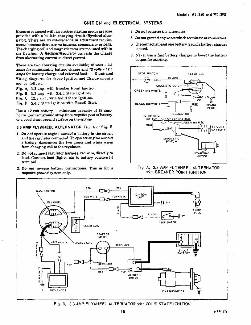
There are two charging circuits available; 72 volts - 3.3 amps for maintaining battery charge and 12 volts - 72.5 amps for battery charge and extemal load. I l lustrated Wiring diagrams for these Ignition and Charge circuits are as follows: Fig. A, 3.3 amp, with Breaker Point Ignition. Fig. 6, 3.3 amp, with .%lid State Ignition. Fig. C, 12.5 amp, with Solid State Ignition. Fig. D, s l id S t a t e Ign i t i on w i th Reco i l Start.
Use a 72 volt battery - minimum capacity of 18 amp hours. Connect ground strap h m negatlve post of battery to a g d clean ground surface on the engine.
3.3 AMP FLYWHEEL ALTERNATOR Fig. A or, Fig. B
1. DO not operate engine without a battery in the circuit and the regulator connected. To operate engine without a battery, disconnect the two green and white wires from charging coil to the regulator.
2. Do nor conned regulator harness, red wire, directly to load. Connect load (lighte, etc. to battery positive (+) terminal.
3. DO not reverse battery connections. This is for a negative ground system only.
output for starting.
STOP SWITCH FLYWHEEL
MAGNETO COIL
GREEN and WHITE
CHARGING COIL
BLACK and WHITE
STARTING REGULATOR
REO T IY
MAGNETIC swmcn
- b P MOTOR
Fig. A, 3.3 AMP FLYWHEEL ALTERNATOR with BREAKER POINT IGNITION
I
Fig. B, 3.3 AMP FLYWHEEL ALTERNATOR with SOLID STATE IGNITION
18 MRP-176