Embed Size (px)
Citation preview
Revised Draft Test Guideline – October 2007
Last saved by huet_m 05/11/2007 1
SURFACEWATERS
SOIL
Wastewater
Sewer**
DirectDischarge
PrimarySolids
Removal
Sludge Digestion**(Anaerobic)
Aerobic**BiologicalTreatment
FinalClarification
SURFACEWATERS
MIXING ZONE**Untreated (Poorly Treated)
Wastewater with Surface Water
PrimaryEffluent
DigestedSludge
SLUDGE AMENDED SOIL
MIXING ZONE**Treated Effluent with Surface Water
FinalEffluent
PrimarySludge Secondary
Sludge
WASTEWATER TREATMENTPLANT
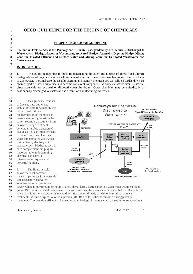
Pathways for ChemicalsDischarged to Wastewater
**Simulated inthe New Guideline
OECD GUIDELINE FOR THE TESTING OF CHEMICALS 1
2 3
PROPOSED OECD 3xx GUIDELINE 4 5 Simulation Tests to Assess the Primary and Ultimate Biodegradability of Chemicals Discharged to 6 Wastewater: Biodegradation in Wastewater, Activated Sludge, Anaerobic Digester Sludge, Mixing 7 Zone for Treated Effluent and Surface water and Mixing Zone for Untreated Wastewater and 8 Surface water 9 10 INTRODUCTION 11
1. This guideline describes methods for determining the extent and kinetics of primary and ultimate 12 biodegradation of organic chemicals whose route of entry into the environment begins with their discharge 13 to wastewater. Personal care, household cleaning and laundry chemicals are typically discarded down the 14 drain as part of their normal use and become consistent components of domestic wastewater. Likewise, 15 pharmaceuticals are excreted or disposed down the drain. Other chemicals may be episodically or 16 continuously discharged to wastewater as a result of manufacturing processes. 17
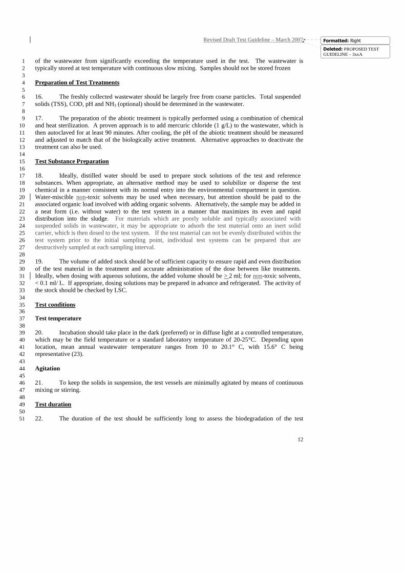
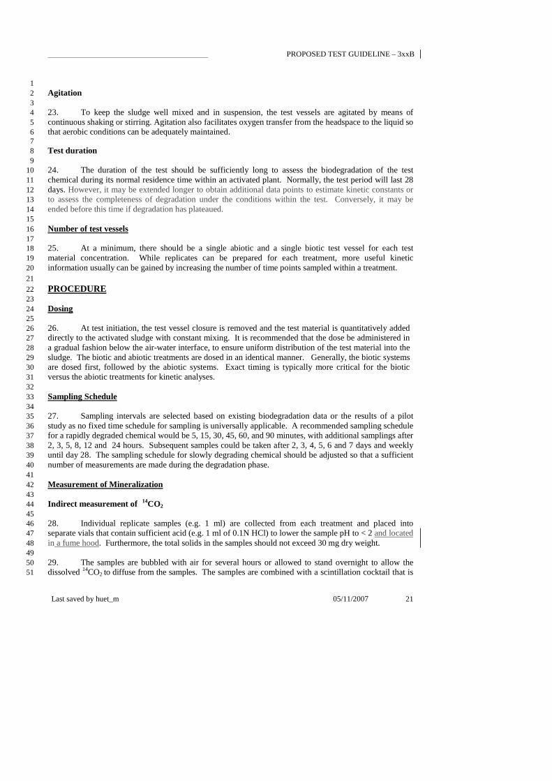
18 2. This guideline consists 20 of five separate but related 22 simulation tests for assessing the 24 primary and ultimate 26 biodegradation of chemicals in 28 wastewater during transit in the 30 sewer, secondary treatment in an 32 activated sludge treatment 34 system, anaerobic digestion of 36 sludge as well as treated effluent 38 in the mixing zone of surface 40 water and untreated wastewater 42 that is directly discharged to 44 surface water. Biodegradation in 46 each compartment can play an 48 important role in determining 50 chemical exposure in 52 interconnected aquatic and 54 terrestrial habitats. 56 58 3. The figure at right 60 shows the most common 62 transport pathways for chemicals 64 discharged to wastewater. 66 Wastewater initially enters a 68 sewer, where it may remain for hours or a few days, during its transport to a wastewater treatment plant 69 (WWTP) or environmental release site. In most situations, the wastewater is treated before release, but in 70 some situations the wastewater is released to surface water directly or with only minimal primary 71 treatment. Within a typical WWTP, a portion (40-60%) of the solids is removed during primary 72 treatment. The resulting effluent is then subjected to biological treatment and the solids are removed in a 73
Revised Draft Test Guideline – March 2007
2
Formatted: Right
final clarifier. The final effluent is subsequently released to surface water. The sludge solids removed 1 during primary treatment and final clarification are most commonly digested under anaerobic conditions if 2 the sludge disposal involves land application. 3 4 4. The fraction of the chemical released to the environment in effluent or associated with sludge 5 solids is a function of its partitioning behaviour and its biodegradation rate. Due to chemical residence 6 time and the level of biological activity, the critical opportunities for significant removal through 7 biodegradation are 1) in the sewer, 2) during aerobic secondary treatment and 3) during anaerobic digestion 8 of the sludge. Consequently, these three systems are the most important to simulate for quantifying 9 biodegradation losses during wastewater transport and treatment. Furthermore, the effects of treatment 10 processes extend into the environment at the time of release. Thus, biodegradation in the mixing zones 11 and in the water as it moves away form the point of release is key to understanding downstream dispersion 12 and exposure. 13
5. The five simulation test methods described are open batch system or closed gas flow-through 14 batch system that include elements from OECD guidelines 301 (1), 303A (2), 309 (3) 310 (4) and 311 (5). 15 The principal objectives of the methods are to 1) measure the rate of primary biodegradation, 2) measure 16 the rate of mineralization, and 3) follow the formation and decay of major transformation products when 17 appropriate. In addition, characterization and quantification of major transformation products may be 18 possible if suitable analytical methods are available. 19 20
6. These tests can be designed to assess accurately the biodegradation of both new and existing 21 chemicals (6, 7, 8, 9, 10, 11) released continuously or episodically to wastewater. In some cases, the 22 resulting kinetic constants can serve as input constants for exposure models used for risk assessment. 23 These tests are intended as higher tier tests for assessing the biodegradation of chemicals, which do not 24 biodegrade in OECD screening tests, or for refining biodegradation rates used for an exposure assessment. 25 26
GENERAL PRINCIPLES OF THE TESTS 27
7. Typically, a test chemical, radiolabelled in an appropriate position, is incubated with an 28 environmental sample, which has been freshly collected from a representative field site or maintained in 29 the laboratory under conditions realistically simulating some future environmental condition. Abiotic and 30 biotic treatments are prepared for each test chemical and condition. Biological activity is inhibited in the 31 abiotic control, which is used for estimating mineralization by difference, establishing extraction 32 efficiency, and recovery of the parent molecule and quantifying other loss processes, such as hydrolysis, 33 oxidation, volatilization or sorption to test apparatus. 34
8. If an analytical method with the required sensitivity is identified, the rate of parent degradation or 35 transformation can be determined using a non-radiolabelled test substance or by following the 36 disappearance of a chemical already in an environmental sample. However, ultimate biodegradation of 37 non-radiolabelled substances cannot be determined unless the biodegradation pathway is well understood 38 and analytical methods with required sensitivity are available for potential metabolites. 39
9. An environmentally relevant concentration of the test material is dosed to both abiotic and biotic 40 test systems. The prepared treatments are incubated at a relevant temperature with continuous mixing when 41 appropriate. Samples are periodically removed for determination of mineralization and primary 42 biodegradation. 43
10. Tests can be performed using an open batch system or a closed gas flow-through batch system 44
Deleted: PROPOSED TEST GUIDELINE – 3xxA
Revised Draft Test Guideline – October 2007
Last saved by huet_m 05/11/2007 3
where traps are used to capture evolved 14CO2 or 14CH4. The closed flow-through system is absolutely 1
mandatory for volatile test materials. It is also usually preferred for 14C-lableled test chemicals. Open 2 systems are appropriate for non-volatile 3H test chemicals and for refining the biodegradation kinetics of 3 non-volatile 14C test materials, whose ability to be mineralized has previously been established. In the 4 open system, mineralization to 14CO2 (
14CH4) can be determined indirectly by measuring the difference in 5 residual radioactivity between samples from the biotic and abiotic treatments following acidification. 6 Similarly, mineralization to 3H2O can be determined indirectly by measuring the difference in residual 7 radioactivity following drying. The open system is not appropriate for use with volatile test materials. In 8 the flow through systems, evolved 14CO2 is measured directly in the base traps. In addition, dissolved 9 14CO2 is determined by acidifying samples in a sealed vessel and measuring radioactivity in a base trap 10 contained in the vessel. Under anaerobic conditions, the evolved 14CO2 and
14CH4 are collected in tandem. 11 The 14CO2 is trapped in base and 14CH4 is combusted and converted to 14CO2, which is subsequently 12 trapped in a similar manner. The choice of test design depends on the type of radiolabel (14C or 3H), the 13 environmental compartment and the properties of the test material. 14
11. Samples from both treatments are analyzed for total radioactivity, extractable parent and 15 metabolites and radioactivity associated with the extracted solids. The level of parent and metabolites is 16 determined using chromatographic separation and radio-analytical detection methods. The solids remaining 17 from the extraction process are combusted to estimate incorporation into biomass by difference or can be 18 further fractionated to determine uptake into various components of biomass. A complete mass balance of 19 the test system is obtained from the sum total of all fractions at each sampling. 20
21 12. The level of parent remaining with time can be analyzed using various decay models to estimate 22 primary biodegradation rates. Likewise, the level of cumulative mineralization can be analyzed using 23 various production models to estimate mineralization rates. 24
APPLICABILITY OF TESTS 25
13. The various tests are designed to assess biodegradation during key phases of wastewater transit as 26 well as treatment and environmental release. The choice of tests should be based on the release scenarios 27 and anticipated properties of the chemical in question. In the case of volatile test materials, appropriate 28 modification must be made to quantify losses due to volatilization. 29 30
3xxA Biodegradation in a Sewer System Test 31
14. The purpose of this test is to evaluate biodegradation in raw wastewater under conditions 32 normally found in sewer systems. Performing this test is useful if there is sufficient time in a sewer for the 33 chemical to undergo significant biodegradation and loss. Hence, it is usually most useful for relatively 34 labile chemicals discharged to large municipal sewer systems. In addition, the test provides data that may 35 be used to determine the concentration of a chemical sorbed to primary sludge. Under the conditions of 36 this test, the level of test chemical is at its expected level in wastewater with the biomass level being that 37 normally present in a representative wastewater sample. While oxygen is present, the system is minimally 38 aerated to simulate dissolved oxygen conditions in sewers. 39
3xxB Biodegradation in Activated Sludge Test 40
15. The purpose of the activated sludge test is to evaluate biodegradation during a widely used form 41 of biological sewage treatment. It is applicable to any chemical subjected to such treatment and is key to 42 estimating final effluent concentrations. It is generally the first and most important test in the series. This 43 test is characterized by a high level of biomass and a relatively low level of test chemical under well-44
Revised Draft Test Guideline – March 2007
4
Formatted: Right
aerated conditions. The activated sludge test can compliment or be a lower cost alternative to the OECD 1 303A, a dynamic simulation of a wastewater treatment plant which can determine the removal of a test 2 chemical under a specific set of operating conditions (i.e. hydraulic retention time, solids residence time, 3 solids level etc.). The OECD 303A can generate a simple removal number or a comprehensive picture of 4 biodegradation and sorption that occur at steady state during treatment. However, as an alternative to the 5 expense and complexity of running a full scale system, the activated sludge test can generate a first order 6 rate constant for the loss of parent and mineralization that can be used as inputs into a variety of 7 wastewater simulation models to estimate removal under any set of operating conditions. 8
3xxC Biodegradation in Anaerobic Digester Sludge Test 9
16. The purpose of anaerobic digester sludge test is to evaluate biodegradation during anaerobic 10 sludge digestion. It is particularly relevant for sorptive chemicals, which partition to primary and 11 secondary sludge. This test is useful for refining the concentration of a chemical present in the sludge 12 leaving a treatment plant as well as demonstrating the potential for anaerobic biodegradation. This test is 13 characterized by reducing conditions, a high level of anaerobic biomass and a level of test chemical based 14 upon expected wastewater concentrations and partitioning behaviour. 15
3xxD Biodegradation in Treated Effluent-Surface water Mixing Zone Test 16
17. The purpose of the effluent mixing zone test is to evaluate the biodegradation of the portion of a chemical 17 that passes through treatment and is released in effluent to surface water and can be used to demonstrate that 18 biodegradation occurring in the treatment plant continues in the receiving environment. It is based upon 19 the principle that both the chemical and microbes degrading that chemical are discharged together in 20 effluent. The results of this test can be used to estimate the reduction in a chemical concentration as a 21 result of biodegradation as a volume of water moves downstream from a wastewater treatment plant. This 22 test is characterized by very low levels of both test chemical and biomass under well-aerated conditions. 23 This test differs from OECD 309 in that the surface water is amended with treated effluent and it can be 24 used to evaluate volatile materials. Also, the OECD 309 focuses largely on mineralization whereas this 25 test is designed to evaluate primary and ultimate biodegradation as well as metabolite formation and 26 disappearance of chemicals discharged to wastewater. 27
3xxE Biodegradation in Untreated Wastewater-Surface water Mixing Zone Test 28
18. The purpose of this test system is to evaluate biodegradation in untreated wastewater that is 29 directly discharged to surface water. This test is useful for determining the relative biodegradation rate for 30 a chemical compared to other organic components in wastewater. Under the conditions of this test, the 31 levels of test chemical and biomass are based upon their expected concentrations in wastewater-surface 32 water mixing zones. Oxygen is present but at reduced levels due to the high level of organic loading. 33
34 INFORMATION ON THE TEST SUBSTANCE 35 36 19. In most cases, 14C or 3H radiolabelled test substances are necessary for this test. For radiolabelled 37 materials, additional unlabelled material may be necessary to achieve the needed test concentration. For 38 substances with low specific activities, the sensitivity of the method can be improved in part by increasing 39 the volume of the analytical samples. 40 41 20. For 14C, the radiolabel should be localized in the most recalcitrant portion of the molecule to 42 monitor comprehensively metabolite formation and decay. In other cases, it may be more appropriate to 43 position the label in a portion of the molecule whose fate is poorly understood. Regardless, interpretation 44
Deleted: PROPOSED TEST GUIDELINE – 3xxA
Revised Draft Test Guideline – October 2007
Last saved by huet_m 05/11/2007 5
of the results must consider the position of the label as it relates to mineralization and the metabolites 1 observed. 2 3 21. Tritiated materials can be an alternative to 14C materials, for reasons of cost or practical 4 synthesis. Tritium labelling often results in random or uniform distribution of tritium atoms in the 5 molecule, which must be taken into account in interpreting mineralization and metabolite patterns. 6 7 22. Non-labelled test substances can be used to determine the rate of parent degradation or 8 transformation if an analytical method with the required sensitivity is identified. 9 10 23. The following information on the test substance is helpful for designing a test: 11 12 - solubility in water [OECD 105] (12); 13 - solubility in organic solvent(s) (substances applied with solvent or with low solubility in water); 14 - dissociation constant (pKa) if the substance is liable to protonation or deprotonation [OECD 112] 15
(13); 16 - vapour pressure [OECD 104] (14) and/or Henry’s law constant; 17 - chemical stability in water and in the dark (hydrolysis) [OECD 111] (15). 18 - environmental concentration, if known or estimated; 19 - toxicity of the test substance to microorganisms [OECD 209] (16); 20 - ready [OECD 301] (1) and/or inherent [OECD 302] (17, 18, 19) biodegradability 21 22
REFERENCE SUBSTANCE 23 24 24. A substance that is normally easily degraded under the test conditions may be useful as reference 25 substance. The purpose of such a reference substance is to ensure that the microbial community in the test 26 system is active. Alternatively, a substance, whose fate in the environment is well understood, may be 27 included as a standard to which the results of the test compound can be compared. While the use of a 28 reference substance is not required, it may provide useful information for the interpretation of the test 29 results. 30
31 QUALITY CRITERIA 32 33 Validity of the Tests 34 35
25. The mass balance from the abiotic treatment is used to confirm the recovery of parent from the 36 test system. It is recommended that an abbreviated pilot die-away study be conducted prior to the 37 definitive test to establish the appropriate extraction system for parent and metabolites. Target recoveries 38 from the test matrix should be 85% -110%; however, these ranges should not be used as criteria for 39 acceptance of the test. If parent recoveries from initial samples taken from the abiotic control are in the 40 targeted range, the sample preparation procedures are suitable for the recovery of the parent compound 41 from the test matrix. Lower than targeted recoveries in the abiotic treatment could be due to poor 42 extraction efficiency, sorption to glassware, or chemical degradation (see below). 43
26. Total recovery of radioactivity in both abiotic and biotic conditions should normally range from 44 75 to 115% in each individual sample, and average total recovery for all samples within a treatment should 45 normally range from 85 to 110%. However, these ranges should not be used as criteria for acceptance of 46 the test. If mass balances from the abiotic treatment are in the targeted range but those in the biotic test 47 system are significantly below this range, the lower recovery likely results from the inability to efficiently 48
Revised Draft Test Guideline – March 2007
6
Formatted: Right
trap 14CO2, recover metabolites or the loss of metabolites to glassware or volatilization. 1
27. If chemical analysis from the abiotic control samples reveals that parent remained intact 2 throughout the experiment, the biodegradation in the biotic treatment can be attributed to microbial 3 activity. If the abiotic treatment indicates degradation of parent over time, interpretation of these results 4 may include a description/explanation of the likely abiotic process that occurred. Comparison between the 5 extent of parent degradation and metabolite formation observed in the two treatments will provide an 6 estimate of the extent of biological versus chemical degradation in the biotic treatment, assuming loss is 7 not an artefact of sample preparation. 8 9 Sensitivity of analytical methods 10 11
28. The limit of detection (LOD) of the analytical method for the test substance and for the 12 transformation products should be < 1% of the initial amount added to the test system if possible. The limit 13 of quantification (LOQ) should be equal to or less than 3% of the added concentration. 14 15 Results with Reference Substance 16 17 29. When a reference substance is included, the results for the reference substance should 18 approximate those anticipated based upon the reasons for its selection. 19 20 21 DATA AND REPORTING 22 23 Plot of data 24 25
30. For each sample, the exact time of incubation including the time needed to terminate biological 26 activity if applicable is reported. Also for each sampling point, the percentage of the dosed radioactivity 27 recovered as parent, metabolites and associated with solids as well as the cumulative amount of 28 mineralization and the total mass balance are reported. These percentages are plotted against time for both 29 the biotic and abiotic treatments, when appropriate. 30 31 Kinetic Analyses (Optional) 32 33 31. It some cases, it may be desirable to fit the results from these tests to kinetic models. These 34 models could include decay models for parent and production models for mineralization (e.g. 14CO2 or 35 3H20). The most common and useful models for this purpose are first-order models. Most exposure 36 models (e.g. EUSES, SimpleTreat) utilize first-order rates as critical input parameters. 37 38 32. A first-order model assumes that the rate constants of a reaction depends solely upon the 39 concentration of the test material. True first-order conditions exist when the test material is below the 40 concentration at which the biodegradative capacity of a system becomes saturated. As the test substance 41 concentration exceeds saturation, the data may still fit a first-order function, but these quasi first-order rates 42 will be slower than a true first-order rate. Such quasi first-order kinetics may arise from a need to test a 43 higher concentration than that occurring in situ due to analytical constraints or simply reflect the actual in 44 situ situation. 45 46 33. When degradation occurs in an exponential manner and the onset of this degradation is not 47 preceded by a lag period during which little or no degradation occurs, it may be possible to fit decay or 48
Deleted: PROPOSED TEST GUIDELINE – 3xxA
Revised Draft Test Guideline – October 2007
Last saved by huet_m 05/11/2007 7
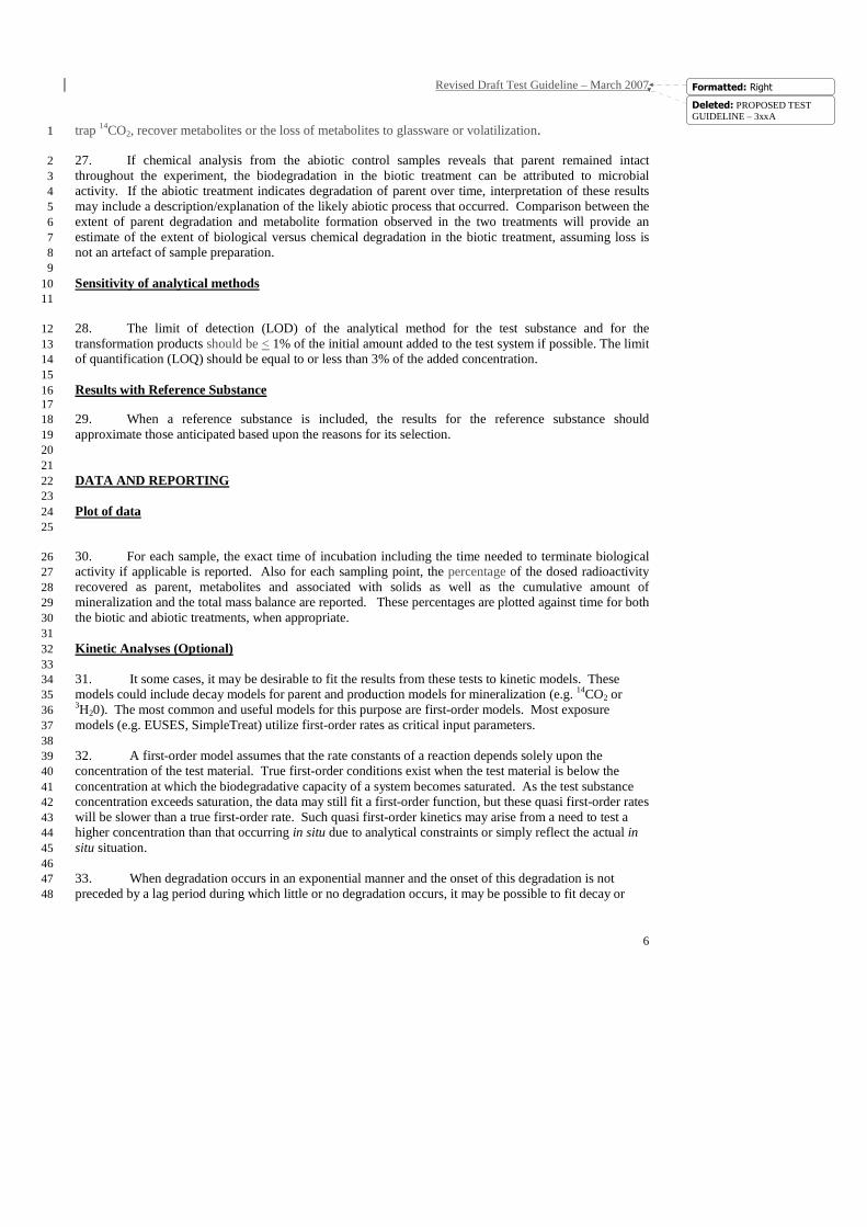
production data to a first-order model. Under such circumstances, the percentage of parent remaining as a 1 function of time may be fitted to a simple or two-compartment first order loss function using nonlinear 2 regression methods. Such equations have the form: 3
tkAey 1−= 4
))+(Be(Aey tktk 21 −−= 5
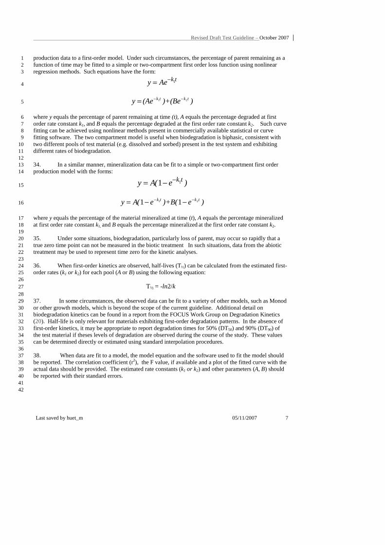
where y equals the percentage of parent remaining at time (t), A equals the percentage degraded at first 6 order rate constant k1, and B equals the percentage degraded at the first order rate constant k2. Such curve 7 fitting can be achieved using nonlinear methods present in commercially available statistical or curve 8 fitting software. The two compartment model is useful when biodegradation is biphasic, consistent with 9 two different pools of test material (e.g. dissolved and sorbed) present in the test system and exhibiting 10 different rates of biodegradation. 11 12 34. In a similar manner, mineralization data can be fit to a simple or two-compartment first order 13 production model with the forms: 14
)e(Ay tk11 −−= 15
)e()+Be(Ay tktk 21 11 −− −−= 16
where y equals the percentage of the material mineralized at time (t), A equals the percentage mineralized 17 at first order rate constant k1, and B equals the percentage mineralized at the first order rate constant k2. 18 19 35. Under some situations, biodegradation, particularly loss of parent, may occur so rapidly that a 20 true zero time point can not be measured in the biotic treatment In such situations, data from the abiotic 21 treatment may be used to represent time zero for the kinetic analyses. 22 23 36. When first-order kinetics are observed, half-lives (T½) can be calculated from the estimated first-24 order rates (k1 or k2) for each pool (A or B) using the following equation: 25 26
T½ = -ln2/k 27 28
37. In some circumstances, the observed data can be fit to a variety of other models, such as Monod 29 or other growth models, which is beyond the scope of the current guideline. Additional detail on 30 biodegradation kinetics can be found in a report from the FOCUS Work Group on Degradation Kinetics 31 (20). Half-life is only relevant for materials exhibiting first-order degradation patterns. In the absence of 32 first-order kinetics, it may be appropriate to report degradation times for 50% (DT50) and 90% (DT90) of 33 the test material if theses levels of degradation are observed during the course of the study. These values 34 can be determined directly or estimated using standard interpolation procedures. 35 36 38. When data are fit to a model, the model equation and the software used to fit the model should 37 be reported. The correlation coefficient (r2), the F value, if available and a plot of the fitted curve with the 38 actual data should be provided. The estimated rate constants (k1 or k2) and other parameters (A, B) should 39 be reported with their standard errors. 40 41 42
Revised Draft Test Guideline – March 2007
8
Formatted: Right
Test Report 1
2
39. The type of study, i.e. wastewater, activated sludge, mixing zone or anaerobic digester sludge test, 3 must be clearly stated in the test report, which shall also contain the following information, when 4 appropriate: 5 6 Test Materials: 7
− common names, chemical names, CAS numbers, structural formulas and relevant physico-8 chemical properties of test and reference substances; 9
− chemical names, CAS numbers, structural formulas and relevant physico-chemical 10 properties of substances used as standards for identification of metabolites; 11
− purities of and nature of known impurities in test and reference substances; 12 − radiochemical purity and specific activity of radiolabelled chemicals; 13 − position within the molecule of radiolabelled atoms. 14
15 Environmental Samples: 16
− source of environmental samples including geographical location and relevant data 17 regarding known prior or existing exposure to the test chemical and related materials; 18
− logic used to estimate relevant environmental concentration; 19 − time, date and field conditions relevant to collection; 20 − temperature, pH, dissolved oxygen (DO) and redox potential as needed; 21 − suspended solids level, biological oxygen demand (BOD), chemical oxygen demand 22
(COD) and Total organic carbon (TOC) as needed; 23 − time between collection and use in the laboratory test, sample storage conditions and any 24
pre-treatment of the sample prior to initiating the test; 25 26
Experimental Conditions: 27 − dates when the study was performed; 28 − amount of test substance applied, test concentration and reference substance; 29 − method of application of the test substance and associated logic for selection; 30 − incubation conditions including lighting, aeration type, temperature; 31 − information on analytical techniques and the method(s) used for radiochemical 32
measurements; 33 − number of replicates; 34
35 Results: 36
− precision and sensitivity of the analytical methods including the limit of detection (LOD) 37 and the level of quantification (LOQ); 38
− recovery for each analyte and disposition of dosed radioactivity at each sampling time and 39 treatment in tabular form; 40
− average mass balance with standard deviation across all time points for each treatment 41 − procedures and models used to estimate biodegradation rates from the data; 42 − biodegradation rates and related parameters with relevant standard errors along with 43
correlation coefficients of determination (R2) and F statistics for the selected models; 44 − additional characterization or identification of any of major metabolites, where appropriate 45
and possible; 46 − a proposed pathway of transformation (optional); 47 − discussion of results. 48
Deleted: PROPOSED TEST GUIDELINE – 3xxA
Revised Draft Test Guideline – October 2007
Last saved by huet_m 05/11/2007 9
3xxA BIODEGRADATION IN A SEWER SYSTEM 1
INTRODUCTION 2
3 1. This test is designed to provide rates of primary and ultimate biodegradation for a chemical in 4 raw wastewater during its time in a sewage conveyance system. It is based on a procedure originally 5 published in Matthijs et al (6). Wastewater contains a large number of microorganisms, capable of 6 degrading a variety of materials. The test duration is typically short term (< 96 hrs) to simulate the 7 residence time in a sewer, but it can be extended to assess the extent to which a chemical can be degraded 8 by wastewater microbes. Performing this test is useful if there is sufficient time in a sewer for the 9 chemical to undergo significant biodegradation and loss. Hence, it is most useful for relatively labile 10 chemicals discharged to large municipal sewer systems. Aeration levels within a sewer can vary widely. 11 To be conservative and simulate the more typical conditions within a sewer, the test is conducted under 12 low dissolved oxygen conditions (< 1 mg/L). In order to achieve this but avoid anoxic conditions (e .g. 13 D.O levels < 0.2 mg/L), D.O, or the corresponding oxygen concentration in the test vessel headspace, 14 should be monitored periodically. Air, oxygen, or nitrogen may be added periodically to the test vessels to 15 maintain DO in this range. 16
2. For existing chemicals consistently present in wastewater, freshly collected wastewater incubated 17 with a tracer level of radiolabelled test chemical will provide the most realistic kinetic parameters 18 regarding the current chemical load. For chemicals not consistently present in wastewater, sufficient test 19 chemical (radiolabelled and unlabelled) should be added to approximate the expected concentration in 20 wastewater during an episodic release or following commercialization of a new chemical. This 21 concentration would reflect the total mass released and the volume of wastewater in which the release is 22 diluted. Approaches for estimating wastewater concentration can be found in Holman (21) and the 23 European Technical Guidance Document (22). In most situations, the chemical and its degrader 24 populations will not be in steady state and the observed kinetics will be quasi first-order or second-order 25 Monod. 26
27
GENERAL TEST PROCEDURE 28
3. The test chemical is incubated with abiotic and biotic wastewater over a period of time under low 29 dissolved oxygen (DO) conditions. Biological activity is inhibited in the abiotic control, which is used for 30 estimating mineralization by difference, determining extraction efficiency and recovery of the parent 31 molecule and quantifying other loss processes, such as hydrolysis, oxidation, volatilization or sorption to 32 test apparatus. 33
4. If an analytical method with the required sensitivity is identified, the rate of parent degradation or 34 transformation can be determined using a non-radiolabelled test substance or by following the 35 disappearance of a chemical already in wastewater. However, ultimate biodegradation can not be 36 determined unless the biodegradation pathway is well understood and analytical methods with required 37 sensitivity are available for potential metabolites. 38
5. An environmentally relevant concentration of the test material is dosed to both abiotic and biotic 39 test systems, which are incubated with continuous slow mixing. The biotic samples are incubated in such a 40 way that dissolved oxygen levels remain at or below 1 mg/L, which are typical for sewage. Samples are 41 periodically removed for determination of mineralization and primary biodegradation. 42
6. Tests can be performed using an open batch system or a sealed, flow-through batch system where 43
Revised Draft Test Guideline – March 2007
10
Formatted: Right
traps are used to capture evolved 14CO2. The closed flow-through system is mandatory for volatile test 1 materials and usually preferred for 14C-lableled test chemicals. Open systems are appropriate for non-2 volatile 3H test chemicals and for refining the biodegradation kinetics of non-volatile 14C test materials, 3 whose ability to be mineralized has previously been established. In the open system, mineralization to 4 14CO2 can be determined indirectly by measuring the difference in residual radioactivity between samples 5 from the biotic and abiotic treatments following acidification. Similarly, mineralization to 3H2O can be 6 determined indirectly by measuring the difference in radioactivity in a sample following drying. In the 7 flow through systems, evolved 14CO2 is measured directly in the base traps. In addition, dissolved 14CO2 is 8 determined by acidifying samples in a sealed vessel and measuring radioactivity in a base trap contained in 9 the vessel. 10
7. Samples from both treatments are analyzed for total radioactivity, extractable parent and 11 metabolites and radioactivity associated with the extracted solids. The level of parent and metabolites is 12 determined using chromatographic separation and when appropriate radio-analytical detection methods. 13 The solids remaining from the extraction process are combusted to estimate incorporation into biomass by 14 difference or can be further fractionated to determine uptake into various components of biomass. A 15 complete mass balance of the test system is obtained from the sum total of all fractions at each sampling. 16 17 APPLICABILITY OF THE TEST 18 19
8. The method is readily applicable to water-soluble or poorly water-soluble materials, which are 20 non-volatile. It can also be adapted for volatile materials. Typically, 14C or 3H -radiolabelling of 21 compounds is required for the assessment of mineralization. Both radiolabelled and non-labelled 22 compound can be used for the assessment of primary biodegradation. 23 24 DESCRIPTION OF THE TEST METHOD 25 26
Test Apparatus 27 28 9. The volume of wastewater in the test treatments is determined based upon the number and 29 volume of the samples needed for the assessment. Typically, 1 to 2 litres of wastewater are placed into 2 30 or 4 litre flasks. Ideally, the wastewater is incubated under controlled DO conditions (typically 0.2-1.0 mg/ 31 L. This condition can be achieved using an oxygen probe immersed in the wastewater attached to an 32 oxygen controller connected to an actuator valve, which monitors and controls the aeration of the 33 wastewater (see Annex 1). This aeration is balanced against continuous sparging with nitrogen to achieve 34 the targeted DO level. Alternatively, the wastewater can be incubated with stirring but minimum aeration 35 to keep the DO levels low, nitrogen or air can be added periodically to maintain D.O level. In this case, 36 DO readings should be reported at regular intervals. 37 38 10. An open test is open to the atmosphere but incubated under conditions that maintain dissolved 39 oxygen levels at the desired level. Flow-through systems are sealed with an appropriate closure containing 40 a sampling port with a valve for removing wastewater samples and connections for influent and effluent 41 gas lines. This closure can be a rubber stopper, but an alternative type of closure may be necessary when 42 working with a volatile hydrophobic test material. When testing volatile compounds, it is recommend that 43 gas lines and sampling tubes consist of inert materials (e.g. Teflon, stainless steel, glass). 44 45 11. The head space of the test vessel is continuously purged with gas at a rate sufficient to maintain 46 the wastewater at the desired DO level but not too fast to prevent efficient trapping of CO2. The test vessel 47 is connected to a series of traps containing potassium hydroxide (e.g. 1.5 N) or other appropriate CO2 48 absorbent. An empty trap is usually included in the trapping train as a precaution against back-flow or 49 condensation. 50
Deleted: PROPOSED TEST GUIDELINE – 3xxA
Revised Draft Test Guideline – October 2007
Last saved by huet_m 05/11/2007 11
1 Equipment 2 3
12. The following standard laboratory equipment are used: 4 5 - miscellaneous glassware and pipettes; 6 - magnetic stirrers or shaker for continuous mixing of the test flasks; 7 - centrifuge; 8 - pH meter; 9 - solid CO2 (dry ice)/acetone or liquid nitrogen bath; 10 - freeze dryer (lyophilizer); 11 - oven or microwave oven for dry weight determinations; 12 - membrane filtration apparatus; 13 - autoclave; 14 - facilities to handle radiolabelled substances; 15 - equipment to quantify 14C and 3H in liquid samples and solid samples (e.g. liquid scintillation 16
counter LSC); 17 - equipment to quantify 14C and 3H in solid samples (e.g. sample oxidizer); 18 - equipment to trap volatilized 14C and 3H from gas trapping system (in-line activated charcoal 19
trap or equivalent); 20 - equipment for thin layer chromatography (TLC) or high performance liquid chromatography 21
(HPLC); 22 - equipment to quantify 14C and 3H for TLC (scanner) or HPLC (in-line detector); 23 - analytical equipment for the determination of the test (and reference) substance if specific 24
chemical analysis is used (e.g. gas chromatograph, high performance liquid chromatograph, 25 mass spectrometry). 26
27 13. The following laboratory equipment is not essential but useful: 28
29 - oxygen meter 30 - oxygen controller with probe and actuator valve. 31 - COD digestion vials 32 - Nitrogen ammonia reagent set 33 - Spectrophotometer 34
35
Selection of Wastewater 36
14. The source of wastewater should be consistent with the objective of the simulation test. For a site 37 specific assessment, the wastewater should be obtained from the specific sewer system in question. For a 38 generic assessment wastewater samples should be predominantly derived from domestic sources. 39 Although difficult to duplicate in practice, the European Technical Guidance Document uses 450 mg/L of 40 suspended solids and 270 mg/L of BOD (biological oxygen demand) as default levels in wastewater (22). 41 In North America, typical wastewaters contain from 100 to 350 mg/L of suspended solids and 110 to 400 42 mg/L of BOD depending upon its strength (23). 43 44 Collection, Transport and Storage of Wastewater 45 46 15. The wastewater should be collected from a sewer access point or at the head of a wastewater 47 treatment plant. The temperature of the sample should be noted at the time of collection. Collection 48 containers should allow for adequate ventilation and measures should be taken to prevent the temperature 49
Revised Draft Test Guideline – March 2007
12
Formatted: Right
of the wastewater from significantly exceeding the temperature used in the test. The wastewater is 1 typically stored at test temperature with continuous slow mixing. Samples should not be stored frozen 2 3 Preparation of Test Treatments 4 5 16. The freshly collected wastewater should be largely free from coarse particles. Total suspended 6 solids (TSS), COD, pH and NH3 (optional) should be determined in the wastewater. 7 8 17. The preparation of the abiotic treatment is typically performed using a combination of chemical 9 and heat sterilization. A proven approach is to add mercuric chloride (1 g/L) to the wastewater, which is 10 then autoclaved for at least 90 minutes. After cooling, the pH of the abiotic treatment should be measured 11 and adjusted to match that of the biologically active treatment. Alternative approaches to deactivate the 12 treatment can also be used. 13 14 Test Substance Preparation 15 16 18. Ideally, distilled water should be used to prepare stock solutions of the test and reference 17 substances. When appropriate, an alternative method may be used to solubilize or disperse the test 18 chemical in a manner consistent with its normal entry into the environmental compartment in question. 19 Water-miscible non-toxic solvents may be used when necessary, but attention should be paid to the 20 associated organic load involved with adding organic solvents. Alternatively, the sample may be added in 21 a neat form (i.e. without water) to the test system in a manner that maximizes its even and rapid 22 distribution into the sludge. For materials which are poorly soluble and typically associated with 23 suspended solids in wastewater, it may be appropriate to adsorb the test material onto an inert solid 24 carrier, which is then dosed to the test system. If the test material can not be evenly distributed within the 25 test system prior to the initial sampling point, individual test systems can be prepared that are 26 destructively sampled at each sampling interval. 27 28 19. The volume of added stock should be of sufficient capacity to ensure rapid and even distribution 29 of the test material in the treatment and accurate administration of the dose between like treatments. 30 Ideally, when dosing with aqueous solutions, the added volume should be > 2 ml; for non-toxic solvents, 31 < 0.1 ml/ L. If appropriate, dosing solutions may be prepared in advance and refrigerated. The activity of 32 the stock should be checked by LSC. 33 34 Test conditions 35 36 Test temperature 37 38 20. Incubation should take place in the dark (preferred) or in diffuse light at a controlled temperature, 39 which may be the field temperature or a standard laboratory temperature of 20-25°C. Depending upon 40 location, mean annual wastewater temperature ranges from 10 to 20.1° C, with 15.6° C being 41 representative (23). 42 43 Agitation 44 45 21. To keep the solids in suspension, the test vessels are minimally agitated by means of continuous 46 mixing or stirring. 47 48 Test duration 49 50 22. The duration of the test should be sufficiently long to assess the biodegradation of the test 51
Deleted: PROPOSED TEST GUIDELINE – 3xxA
Revised Draft Test Guideline – October 2007
Last saved by huet_m 05/11/2007 13
chemical during its normal residence time within the sewer system. However, it may be extended longer to 1 obtain additional data points to estimate kinetic constants or to assess the completeness of degradation 2 under the conditions within the test. Conversely, it may be ended before this time if degradation has 3 plateaued. 4 5 Number of test vessels 6 7 23. At a minimum, there should be a single abiotic and a single biotic test vessel for each test 8 material concentration. While replicates can be prepared for each treatment, more useful kinetic 9 information usually can be gained by increasing the number of time points sampled within a treatment. 10 11 PROCEDURE 12 13 Dosing 14 15 24. At test initiation, the test vessel closure is removed and the test material is quantitatively added 16 directly to the treatment with constant mixing. It is recommended that the dose be administered in a 17 gradual fashion below the air-water interface, to ensure uniform distribution of the test material into the 18 wastewater. The biotic and abiotic treatments are dosed in an identical manner. Generally, the biotic 19 systems are dosed first, followed by the abiotic systems. Exact timing is typically more critical for the 20 biotic versus the abiotic treatments for kinetic analyses. 21 22 Sampling Schedule 23 24 25. Sampling intervals are selected based on existing biodegradation data or the results of a pilot 25 study as no fixed time schedule for sampling is universally applicable. A recommended sampling schedule 26 for a rapidly degraded chemical would be 15, 30 and 60 minutes, with additional samplings after 2, 5, 8, 12 27 and 24 hours and day 2, 3 and 4. The sampling schedule for slowly degrading chemical should be adjusted 28 so that a sufficient number of measurements are made during the degradation phase. 29 30 Measurement of Mineralization 31 32 Indirect measurement of 14CO2 33 34 26. Individual replicate samples (e.g. 1 ml) are collected from each treatment and placed into 35 separate vials that contain sufficient acid (e.g. 1 ml of 0.1N HCl) to lower the sample pH to < 2 and located 36 in a fume hood. 37 38 27. The samples are bubbled with air for several hours or allowed to stand overnight to allow the 39 dissolved 14CO2 to diffuse from the samples. The samples are combined with a scintillation cocktail that is 40 suitable for the sample matrix and analysed by LSC. The percent of 14CO2 is calculated based upon the 41 difference between the total counts in the biotic and abiotic samples. 42 43 Direct measurement of 14CO2 44 45 28. Evolved 14CO2:
The first base trap in the series is removed and quickly capped. The remaining 46 traps are moved forward in the same order and a fresh trap placed behind the existing traps and the 47 trapping system reconnected as quickly as possible. Replicate subsamples (e.g. 1 ml) from the base trap 48 are removed and transferred to scintillation vials and combined with a scintillation cocktail that is suitable 49 for the sample matrix and analysed by LSC. 50 51
Revised Draft Test Guideline – March 2007
14
Formatted: Right
29. Dissolved 14CO2: Samples (e.g. 10 to 25 ml) are removed through the sampling port of the test 1 flask. They are then placed in vessels (e.g. Bellco Glass Biometer 2556-10250) containing a compartment 2 with an appropriate CO2 absorbent (e.g. 1.5 N KOH). The vessels are sealed and sufficient acid is added to 3 lower the pH of the samples to < 2 without opening the vessels to the atmosphere (see Annex 1). The 4 samples are allowed to sit for a sufficient length of time (e.g. overnight) to allow CO2 to diffuse from 5 solution and be trapped from the headspace by the sorbent. Samples of the sorbent are combined with a 6 scintillation cocktail that is suitable for the sample matrix and analysed by LSC. 7 8 Indirect measurement of 3H2O 9 10 30. Individual replicate samples (e.g. 1 ml) are collected from each treatment and placed into 11 separate vials that contain sufficient acid (e.g. 1 ml of 0.1N HCl) to lower the sample pH to < 2 and located 12 in a fume hood. 13 . 14 15 31. Half of the samples are immediately analysed directly by LSC for a “wet measurement”. The 16 remaining samples are allowed to dry completely to remove the 3H2O. The samples are combined with a 17 scintillation cocktail that is suitable for the sample matrix and analysed by LSC. The percent 3H2O is 18 calculated based upon the difference between the total counts in the wet and dry samples and the initial 19 level of radioactivity dosed to the samples. 20 21 22
Measurement of Total Radioactivity in Wastewater 23 24
32. Replicate small volume samples (e.g. 1 ml) are analysed directly by LSC to quantify the 25 radioactivity remaining in each treatment over time. These measurements are used to confirm that the 26 recovery of radioactivity from the extracted samples is acceptable and to monitor for volatilization. 27 28
Measurement of Parent and Metabolites 29 30 Extraction 31 32 33. A sample is collected from both the abiotic and biotic treatments. The sample volume is 33 typically > 10 ml. However, the size will depend on the test concentration, specific activity and the 34 sensitivity of the analytical procedures. 35 36 34. Various approaches can be used for concentrating and extracting the samples. A proven 37 approach for nonvolatile test chemicals involves flash freezing the samples, followed by lyophilization and 38 extraction of the dried residue with appropriate solvent(s) for parent and metabolites. Flash freezing 39 quickly stops biological activity without hydrolyzing or otherwise altering labile test materials. The dried 40 solids are extracted and the resulting extracts can be concentrated through evaporation and the total 41 radioactivity in each extract is determined by LSC. 42 43 35. For volatile test materials, the sample can be passed through a filter and solid phase extraction 44 (SPE) column or SPE disk placed in tandem, which are subsequently eluted with appropriate solvents to 45 recover parent and metabolites. Alternatively, samples can be centrifuged, and parent and metabolites can 46 be extracted from the liquor by solid phase or liquid/liquid extraction. The solids can then be extracted 47 directly or mixed with a drying agent (e.g. sodium sulfate) and allowed to dry prior to extraction with an 48 appropriate solvent system. An alternative is to extract the solids and dry the extract by running the solvent 49 through a column containing a drying agent. In some cases, it may be possible to directly extract the 50 entire aqueous sample with an appropriate solvent system and then filter it to recover biomass solids. The 51
Deleted: PROPOSED TEST GUIDELINE – 3xxA
Revised Draft Test Guideline – October 2007
Last saved by huet_m 05/11/2007 15
total radioactivity in all extracts is determined by LSC. Care must be taken in concentrating extracts 1 containing volatile test materials or metabolites. The recovery in the abiotic treatment are used to 2 3 36. Other approaches can be utilized, but with all approaches it is important to document recoveries 4 and consider the time involved in terminating biological activity and factor it into the sample times used 5 for kinetic analyses. 6 7 Analysis of Parent and Metabolites 8 9 37. The relative abundance of parent and metabolites within the extracts can be determined using thin 10 layer chromatography (TLC), high performance liquid chromatography (HPLC) or other separation 11 techniques with radioactivity detection. 12 13 38. If sensitive specific analytical methods are available, primary biodegradation can be assessed by 14 measuring the total residual concentration of test substances and metabolites instead of using radioisotope 15 techniques. 16 17 Characterization of Metabolites 18 19 39. Whenever possible, the chromatographic behaviour of unknown peaks should be compared to 20 that of predicted metabolites, if authentic standards exist. Usually, the quantity and purity of metabolites 21 generated in this test make definitive identification by other direct means impossible. Depending upon 22 chromatographic behaviour, it is usually possible to determine if a metabolite is more or less polar than the 23 parent. This information combined with known biochemical reactions along with when a metabolite 24 appears and disappears in the sequence of biodegradation can form an additional basis for inferring its 25 identity. If necessary, the Kow of major metabolites can be determined by HPLC (e.g. [OECD 117] (24)) 26 using an on-line radioactivity detector. 27 28 Measurement of Extracted Solids and Incorporation into Biomass 29 30 40. If the extracted samples are filtered, the filter will retain carbonate salts as well as 31 microorganisms from the test system. The filter containing the biosolids is placed into a scintillation vial 32 and acidified to pH <2 by submerging it in a weak acid solution (e.g. 1 ml of 0.1N HCl). The samples are 33 allowed to sit for sufficient time (e.g. overnight) for the dissolved 14CO2 to diffuse from the samples. The 34 samples are analyzed by LSC. In the case of non-filtered extracted solids, they are combusted to determine 35 the level of activity remaining with the solids. The level of radioactivity in the biotic solids above that in 36 solids from the abiotic control typically represents incorporation of radioactivity into biomass. The 37 distribution of this radioactivity among various components of biomass (i.e. nucleic acids, protein, cell 38 wall, etc.) can be determined using a modified Sutherland and Wilkinson procedure (7, 24). 39 40 Measurement of Volatilized Radioactivity 41 42 41. For volatile test materials, the volatile traps are extracted with appropriate solvents and the 43 radioactivity in the extracts is analyzed by LSC. The relative abundance of parent and metabolites in the 44 extract(s) can be determined as described above. 45
46

PROPOSED TEST GUIDELINE – 3xxB
Last saved by huet_m 05/11/2007 17
3xxB BIODEGRADATION IN ACTIVATED SLUDGE 1
INTRODUCTION 2
1. This test is designed to assess the extent to which a chemical can be degraded in activated sludge 3 and to provide rates of primary and ultimate biodegradation under the conditions of the test. It is based on 4 a procedure originally published by Federle & Itrich (7). Activated sludge in its various configurations is 5 the most common secondary wastewater treatment process. The usefulness of the measured rates for 6 accurately predicting removal in actual treatment using wastewater treatment models (e.g. SimpleTreat) 7 will be a function of the fidelity of the simulation to actual conditions within an activated sludge 8 wastewater treatment plant. 9
2. Four factors determine the test material concentration in this guideline:, 1) whether the material is 10 released continuously or episodically, 2) current presence in the environment, 3) expected presence in the 11 environment for a new chemical and 4) analytical sensitivity. 12
3. When a chemical is already present in the environment in a continuous fashion, the most 13 accurate kinetics are obtained by adding a tracer level of the radiolabelled material to freshly obtained 14 environmental samples. Under these circumstances, the normal ratio of chemical to degraders is not 15 disrupted and the observed rates reflect those occurring in situ. 16
4. When a new chemical will be released continuously at some future time, the most accurate rates 17 are obtained when the chemical and degrader populations are in a steady state balance. This situation can 18 be achieved by adding a tracer level of test chemical to activated sludge, which has been exposed to the 19 chemical under expected loading and operating conditions in a laboratory continuous activated sludge 20 system (e.g. OECD 303 A). 21
5. When an existing or new chemical enters the environment in an episodic manner, there is not a 22 normal steady state ratio of biomass to test chemical to disrupt so the test chemical is dosed to freshly 23 collected samples at its expected level in wastewater during a release event. This concentration should 24 reflect the total mass released and the volume of wastewater in which the release is diluted. Approaches 25 for estimating wastewater concentration can be found in Holman (21) and the European Technical 26 Guidance Document (22). 27
6. Superseding the previous considerations is analytical sensitivity. When it is not possible to use 28 ideal (e.g. tracer) levels of test chemical due to analytical consideration, the lowest possible concentration 29 is employed. At high test material concentrations, biodegradation may be associated with lags related to 30 second–order processes (i.e. growth), which complicate the kinetic analysis. When this standard for 31 simulation is not achieved, observed biodegradation rates may not be fully representative, which should be 32 considered in the interpretation of the results. This factor is particularly important for continuously 33 released chemicals, which often reach steady state conditions in wastewater systems. 34
GENERAL TEST PROCEDURE 35
7. The test chemical is incubated with abiotic and biotic activated sludge over a period of time. 36 Biological activity is inhibited in the abiotic control, which is used for estimating mineralization by 37 difference, establishing extraction efficiency and recovery of the parent molecule and quantifying other 38 loss processes, such as hydrolysis, oxidation, volatilization or sorption to test apparatus. 39
8. If an analytical method with the required sensitivity is identified, the rate of parent degradation or 40 transformation can be determined using a non-radiolabelled test substance or by following the 41
PROPOSED TEST GUIDELINE – 3xxB
disappearance of a chemical already in wastewater. However, ultimate biodegradation can not be 1 determined unless the biodegradation pathway is well understood and analytical methods with required 2 sensitivity are available for potential metabolites. 3
9. An environmentally relevant concentration of the test material is dosed to both abiotic and biotic 4 test systems, which are incubated at a relevant temperature with continuous mixing when appropriate. 5 Samples are periodically removed for determination of mineralization and primary biodegradation. 6
10. Tests can be performed using an open batch system or a sealed, flow-through batch system where 7 traps are used to capture evolved 14CO2. The closed flow-through system is mandatory for volatile test 8 materials and usually preferred for 14C-lableled test chemicals. Open systems are appropriate for non-9 volatile 3H test chemicals and for refining the biodegradation kinetics of non-volatile 14C test materials, 10 whose ability to be mineralized has previously been established. In the open system, mineralization to 11 14CO2 can be determined indirectly by measuring the difference in residual radioactivity between samples 12 from the biotic and abiotic treatments following acidification. Similarly, mineralization to 3H2O can be 13 determined indirectly by measuring the difference in radioactivity in a sample following drying. In the 14 flow through systems, evolved 14CO2 is measured directly in the base traps. In addition, dissolved 14CO2 is 15 determined by acidifying samples in a sealed vessel and measuring radioactivity in a base trap contained in 16 the vessel. 17
11. Samples from both treatments are analyzed for total radioactivity, extractable parent and 18 metabolites and radioactivity associated with the extracted solids. The level of parent and metabolites is 19 determined using chromatographic separation and when appropriate radio-analytical detection methods. 20 The solids remaining from the extraction process are combusted to estimate incorporation into biomass by 21 difference or can be further extracted using a modified Sutherland and Wilkinson procedure (7) to 22 determine uptake into various components of biomass. A complete mass balance of the test system is 23 obtained from the sum total of all fractions at each sampling. 24 25 APPLICABILITY OF THE TEST 26 12. The method is readily applicable to water-soluble or poorly water-soluble materials, which are 27 non-volatile. It can also be adapted for volatile materials. Typically, 14C or 3H -radiolabelling of 28 compounds is required for the assessment of mineralization. Both radiolabelled and non-labelled 29 compound can be used for the assessment of primary biodegradation. 30 31 DESCRIPTION OF THE TEST METHOD 32 33
Test Apparatus 34 35 12. The volume of activated sludge in the test treatments is determined based upon the number and 36 volume of the samples needed for the assessment. Typically, 1 to 2 litres of sludge are placed into 2 or 4 37 liter flasks. Open batch tests are generally closed with a foam or cotton stopper to minimize evaporative 38 loss of water. Flow-through systems are sealed with an appropriate closure containing a sampling port 39 with a valve for removing MLSS samples and connections for influent and effluent gas lines (see Annex 40 1). This closure can be a rubber stopper, but glass is recommended when working with a volatile 41 hydrophobic test material. When testing volatile compounds, it also is recommend that gas lines and 42 sampling tubes consist of inert materials (e.g. Teflon, stainless steel, glass). 43 44 45 46 13. The head space of the test vessel is continuously purged with air or CO2-free air at a rate 47 sufficient to maintain the activated sludge in an aerobic condition but not too fast to prevent efficient 48
PROPOSED TEST GUIDELINE – 3xxB
Last saved by huet_m 05/11/2007 19
trapping of CO2. The test vessel is connected to a series of traps containing potassium hydroxide (e.g. 1.5 1 N) or other appropriate CO2 absorbent. An empty trap is usually included in the trapping train as a 2 precaution against back-flow or condensation. 3 4 Equipment 5 6
14. The following standard laboratory equipment are used: 7 8 - miscellaneous glassware and pipettes; 9 - magnetic stirrers or shaker for continuous mixing of the test flasks; 10 - centrifuge; 11 - pH meter; 12 - solid CO2 (dry ice)/acetone or liquid nitrogen bath; 13 - freeze dryer (lyophilizer); 14 - oven or microwave oven for dry weight determinations; 15 - membrane filtration apparatus; 16 - autoclave; 17 - facilities to handle radiolabelled substances; 18 - equipment to quantify 14C and 3H in liquid samples and solid samples (e.g. liquid scintillation 19
counter LSC); 20 - equipment to quantify 14C and 3H in solid samples (e.g. sample oxidizer); 21 - equipment to trap volatilized 14C and 3H from gas trapping system (in-line activated 22
charcoal trap or equivalent); 23 - equipment for thin layer chromatography (TLC) or high performance liquid chromatography 24
(HPLC); 25 - equipment to quantify 14C and 3H for TLC (scanner) or HPLC (in-line detector); 26 - analytical equipment for the determination of the test (and reference) substance if specific 27
chemical analysis is used (e.g. gas chromatograph, high performance liquid chromatograph, 28 mass spectrometer). 29
Selection of Activated Sludge Source 30
15. The source of activated sludge should be consistent with the objective of the simulation test. For 31 a site specific assessment, the activated sludge should be obtained from the specific wastewater treatment 32 plant in question. For a generic assessment activated sludge should be obtained from a typical wastewater 33 treatment plant receiving predominantly domestic wastewater. If the chemical is currently a component of 34 wastewater entering the wastewater treatment facility or is episodically released to wastewater, freshly 35 collected activated sludge will be ideal for the test. 36
16. For a new chemical which will be continuously released to wastewater, activated sludge ideally 37 should be obtained from a laboratory scale treatment system such as a porous pot or CAS [OECD 303A] 38 (2), which has been fed wastewater amended with unlabelled test material. The source of the starting 39 sludge, wastewater (influent) and the operating conditions (influent concentration, hydraulic retention time, 40 solids retention time) for the laboratory unit should accurately reflect site specific or generic conditions. In 41 the case of the latter, the European Technical Guidance Document specifies a hydraulic retention time 42 (HRT) of 6.9 hours and a sludge retention time (SRT) of 9.2 days in its generic scenario for wastewater 43 treatment (22). The European Technical Guidance Document also provides guidance on estimating 44 wastewater concentration based upon expected usage volumes. In general, steady state will be reached 45 within 2 to 3 times the SRT after which point the sludge can be used for testing. 46 47 Collection, Transport and Storage of Activated Sludge 48
PROPOSED TEST GUIDELINE – 3xxB
1 17. The activated sludge should be collected from a well mixed region of the aeration basin. The 2 temperature of the sample should be noted at the time of collection. Collection containers should allow 3 for adequate ventilation and measures should be taken to prevent temperature of the sludge from 4 significantly exceeding the temperature used in the test. The activated sludge is typically stored at test 5 temperature with continuous aeration. Samples should not be stored frozen. 6 7 Preparation of the Test Treatments 8 9 Activated Sludge 10 11 18. The activated sludge should be sieved through a 2mm screen prior to use. The total suspended 12 solids (TSS) concentration should be measured and if necessary adjusted to the targeted concentration. 13 The European Technical Guidance Document uses a default level of 4000 mg/L in its generic scenario 14 (22). However, 2500 – 3000 mg/L may be more typical for North America (23). The sludge can be 15 diluted with liquor or tap water if the solids concentration is too high. Alternatively if the solids 16 concentration is too low, the solids can be allowed to settle and some of the liquor can be decanted. A 17 final TSS level and pH should then be determined. 18 19 19. The preparation of the abiotic sludge is typically performed using a combination of chemical and 20 heat sterilization. A proven approach is to add mercuric chloride solution (1 g/L) to the sludge, which is 21 then autoclaved for at least 90 minutes. After cooling, the pH of the abiotic sludge should be measured and 22 adjusted to match that of the biologically active sludge. Alternative approaches to deactivate the sludge 23 can also be used. 24 25 Test Substance Preparation 26 27 20. Ideally, distilled water should be used to prepare stock solutions of the test and reference 28 substances. When appropriate, an alternative method may be used to solubilize or disperse the test 29 chemical in a manner consistent with its normal entry into the environmental compartment in question. 30 Water-miscible non-toxic solvents may be used when necessary, but attention should be paid to the 31 associated organic load involved with adding organic solvents. Alternatively, the sample may be added in 32 a neat form to the test system in a manner that maximizes its even and rapid distribution into the sludge. 33 For materials which are poorly soluble and typically associated with suspended solids in wastewater, it 34 may be appropriate to adsorb the test material onto an inert solid carrier, which is then dosed to the test 35 system. If the test material can not be evenly distributed within the test system prior to the initial 36 sampling point, individual test systems can be prepared that are destructively sampled at each sampling 37 interval. 38 39 21. The volume of added stock should be of sufficient capacity to ensure rapid and even distribution 40 of the test material in the treatment and accurate administration of the dose between like treatments. 41 Ideally, when dosing with aqueous solutions, the added volume should be > 2 ml; for non-toxic solvents, 42 < 0.1 ml/ L. If appropriate, dosing solutions may be prepared in advance and refrigerated. The activity of 43 the stock should be checked by LSC. 44 45 Test conditions 46 47 Test temperature 48 49 22. Incubation should take place in the dark (preferred) or in diffuse light at a controlled temperature, 50 which may be the field temperature or a standard laboratory temperature of 20-25°C. 51
PROPOSED TEST GUIDELINE – 3xxB
Last saved by huet_m 05/11/2007 21
1 Agitation 2 3 23. To keep the sludge well mixed and in suspension, the test vessels are agitated by means of 4 continuous shaking or stirring. Agitation also facilitates oxygen transfer from the headspace to the liquid so 5 that aerobic conditions can be adequately maintained. 6 7 Test duration 8 9 24. The duration of the test should be sufficiently long to assess the biodegradation of the test 10 chemical during its normal residence time within an activated plant. Normally, the test period will last 28 11 days. However, it may be extended longer to obtain additional data points to estimate kinetic constants or 12 to assess the completeness of degradation under the conditions within the test. Conversely, it may be 13 ended before this time if degradation has plateaued. 14 15 Number of test vessels 16 17 25. At a minimum, there should be a single abiotic and a single biotic test vessel for each test 18 material concentration. While replicates can be prepared for each treatment, more useful kinetic 19 information usually can be gained by increasing the number of time points sampled within a treatment. 20 21 PROCEDURE 22 23 Dosing 24 25 26. At test initiation, the test vessel closure is removed and the test material is quantitatively added 26 directly to the activated sludge with constant mixing. It is recommended that the dose be administered in 27 a gradual fashion below the air-water interface, to ensure uniform distribution of the test material into the 28 sludge. The biotic and abiotic treatments are dosed in an identical manner. Generally, the biotic systems 29 are dosed first, followed by the abiotic systems. Exact timing is typically more critical for the biotic 30 versus the abiotic treatments for kinetic analyses. 31 32 Sampling Schedule 33 34 27. Sampling intervals are selected based on existing biodegradation data or the results of a pilot 35 study as no fixed time schedule for sampling is universally applicable. A recommended sampling schedule 36 for a rapidly degraded chemical would be 5, 15, 30, 45, 60, and 90 minutes, with additional samplings after 37 2, 3, 5, 8, 12 and 24 hours. Subsequent samples could be taken after 2, 3, 4, 5, 6 and 7 days and weekly 38 until day 28. The sampling schedule for slowly degrading chemical should be adjusted so that a sufficient 39 number of measurements are made during the degradation phase. 40 41 Measurement of Mineralization 42 43 Indirect measurement of 14CO2 44 45 28. Individual replicate samples (e.g. 1 ml) are collected from each treatment and placed into 46 separate vials that contain sufficient acid (e.g. 1 ml of 0.1N HCl) to lower the sample pH to < 2 and located 47 in a fume hood. Furthermore, the total solids in the samples should not exceed 30 mg dry weight. 48 49 29. The samples are bubbled with air for several hours or allowed to stand overnight to allow the 50 dissolved 14CO2 to diffuse from the samples. The samples are combined with a scintillation cocktail that is 51
PROPOSED TEST GUIDELINE – 3xxB
suitable for the sample matrix and analysed by LSC. The percent of 14CO2 is calculated based upon the 1 difference between the total counts in the biotic and abiotic samples. 2 3 Direct measurement of 14CO2 4 5 30. For rapidly degrading chemicals, it can be difficult to measure accurately the rate of 14CO2 evolved 6 due to the rate of the mass transfer of 14CO2 from the headspace into the base trap. Under these conditions, it is 7 recommended that indirect measurement of 14CO2 be conducted simultaneously with direct measurement. 8 9 31. Evolved 14CO2:
The first base trap in the series is removed and quickly capped. The remaining 10 traps are moved forward in the same order and a fresh trap placed behind the existing traps and the 11 trapping system reconnected as quickly as possible. Replicate subsamples (e.g. 1 ml) from the base trap 12 are removed and transferred to scintillation vials and combined with a scintillation cocktail that is suitable 13 for the sample matrix and analysed by LSC. 14 15 32. Dissolved 14CO2: Samples (e.g. 10 to 25 ml) are removed through the sampling port of the test 16 flask. They are then placed in vessels (e.g. Bellco Glass Biometer 2556-10250) containing a compartment 17 with an appropriate CO2 absorbent (e.g. 1.5 N KOH). The vessels are sealed and sufficient acid is added to 18 lower the pH of the samples to < 2 without opening the vessels to the atmosphere (see Annex 1). The 19 samples are allowed to sit for a sufficient length of time (e.g. overnight) to allow CO2 to diffuse from 20 solution and be trapped from the headspace by the sorbent. Samples of the sorbent are combined with a 21 scintillation cocktail that is suitable for the sample matrix and analysed by LSC. 22 23 Indirect measurement of 3H2O 24 25 33. Individual replicate samples (e.g. 1 ml) are collected from each treatment and placed into 26 separate vials that contain sufficient acid (e.g. 1 ml of 0.1N HCl) to lower the sample pH to < 2 and located 27 to a fume hood. Furthermore, the total solids in the samples should not exceed 30 mg dry weight. 28 29 34. Half of the samples are immediately analysed directly by LSC for a “wet measurement”. The 30 remaining samples are allowed to dry completely to remove the 3H2O. The samples are combined with a 31 scintillation cocktail that is suitable for the sample matrix and analysed by LSC. The percent 3H2O is 32 calculated based upon the difference between the total counts in the wet and dry samples and the initial 33 level of radioactivity dosed to the samples. 34 35 Measurement of Radioactivity in Mixed-Liquor Suspended Solids (MLSS) 36 37
35. Small volume samples of MLSS (e.g. 1 ml) are analysed directly by LSC to quantify the 38 radioactivity remaining in each treatment over time. These measurements are used to confirm that the 39 recovery of radioactivity from the extracted samples is acceptable and to monitor for volatilization. The 40 total solids in these samples should not exceed 30 mg dry weight to avoid counting efficiency problems. 41 42
Measurement of Parent and Metabolites 43 44 Extraction 45 46 36. A sample of MLSS is collected from both the abiotic and biotic treatments. The sample volume 47 is typically > 10 ml. However, the size will depend on the test concentration, specific activity and the 48 sensitivity of the analytical procedures. 49 50 37. Various approaches can be used for concentrating and extracting the samples. A proven 51
PROPOSED TEST GUIDELINE – 3xxB
Last saved by huet_m 05/11/2007 23
approach for nonvolatile test chemicals involves flash freezing the samples, followed by lyophilization and 1 extraction of the dried residue with appropriate solvent(s) for parent and metabolites. Flash freezing 2 quickly stops biological activity without hydrolyzing or otherwise altering labile test materials. The 3 resulting extracts can be concentrated through evaporation and the total radioactivity in each extract is 4 determined by LSC. 5 6 38. For volatile test materials, MLSS can be passed through a filter and solid phase extraction (SPE) 7 column or SPE disk placed in tandem, which are subsequently eluted with appropriate solvents to recover 8 parent and metabolites. Alternatively, samples can be centrifuged, and parent and metabolites can be 9 extracted from the liquor by solid phase or liquid/liquid extraction. The solids can then be extracted 10 directly or mixed with a drying agent (e.g. sodium sulfate) and allowed to dry prior to extraction with an 11 appropriate solvent system. An alternative is to extract the solids and then remove the water from the 12 solvent by running it through a column containing a drying agent. In most cases, it is not efficient to use 13 liquid/liquid extraction to recover parent and metabolites from MLSS. The total radioactivity in all 14 extracts is determined by LSC. Care must be taken in concentrating extracts containing volatile test 15 materials or metabolites. 16 17 39. Other approaches can be utilized, but with all approaches it is important to document recoveries 18 and consider the time involved in terminating biological activity and factor it into the sample times used 19 for kinetic analyses. 20 21 Analysis of Parent and Metabolites 22 23 40. The relative abundance of parent and metabolites within the extracts can be determined using thin 24 layer chromatography (TLC), high performance liquid chromatography (HPLC) or other separation 25 techniques with radioactivity detection. 26 27 41. If sensitive specific analytical methods are available, primary biodegradation can be assessed by 28 measuring the total residual concentration of test substances and metabolites instead of using radioisotope 29 techniques. 30 31 Characterization of Metabolites 32 33 42. Whenever possible, the chromatographic behaviour of unknown peaks should be compared to 34 that of predicted metabolites, if authentic standards exist. Usually, the quantity and purity of metabolites 35 generated in this test make definitive identification by other direct means impossible. Depending upon 36 chromatographic behaviour, it is usually possible to determine if a metabolite is more or less polar than the 37 parent. This information combined with known biochemical reactions along with when a metabolite 38 appears and disappears in the sequence of biodegradation can form an additional basis for inferring its 39 identity. If necessary, the Kow of major metabolites can be determined by HPLC (e.g. OECD 117 (24)) 40 using an on-line radioactivity detector. 41 42 Measurement of Extracted Solids and Incorporation into Biomass 43 44 43. The extracted solids are combusted to determine the level of activity remaining with the solids. 45 The level of radioactivity in the biotic solids above that in solids from the abiotic control typically 46 represents incorporation of radioactivity into biomass. The distribution of this radioactivity among various 47 components of biomass (i.e. nucleic acids, protein, cell wall, etc.) can be determined using a modified 48 Sutherland and Wilkinson procedure (7, 24). 49 50 Measurement of Volatilized Radioactivity 51

PROPOSED TEST GUIDELINE – 3xxB
1 44. For volatile test materials, the volatile traps are extracted with appropriate solvents and the 2 radioactivity in the extracts is analyzed by LSC. The relative abundance of parent and metabolites in the 3 extract(s) can be determined as described above. 4
5
PROPOSED TEST GUIDELINE – 3xxC
Last saved by huet_m 05/11/2007 25
3xxC MINERALIZATION AND TRANSFORMATION IN ANAEROBIC DIGESTER 1 SLUDGE 2
INTRODUCTION 3
4 1. This test is designed to assess the extent to which a chemical can be degraded during anaerobic 5 digestion. It also provides rates of primary and ultimate biodegradation under the conditions within a 6 digester. Anaerobic digestion is commonly used to stabilize and reduce the mass of sludge generated by 7 wastewater treatment plants. Biodegradation during anaerobic digestion is particularly relevant for 8 chemicals with a high tendency to partition to primary and secondary sludge. Removal during anaerobic 9 digestion can significantly decrease the level of a chemical present in sludge used as a soil amendment. 10 The test is also easily adaptable for septage to evaluate anaerobic biodegradation in septic tanks. 11
2. Given that many digesters are operated as batch or plug-flow systems, which have long residence 12 times (30 – 60 days), it is not essential that the chemical and its degrader populations be in steady state at 13 the initiation of a test to generate useful rates for exposure assessments. 14
3. To simulate conditions associated with episodic release of a chemical, freshly collected digester 15 sludge can be incubated with the maximum concentration of test chemical expected to occur in sludge as a 16 result of periodic releases. Approaches for estimating expected sludge concentrations can be found in 17 Holman (21) and the European Technical Guidance Document (22). For existing chemicals continuously 18 discharged to wastewater, freshly collected digester sludge can be incubated with a tracer level of 19 radiolabelled test chemical or the expected concentration to occur in digester sludge. Usually, sufficient 20 time is available for acclimating new chemicals within the time frame of the test. However, a laboratory 21 anaerobic reactor operated in a draw and fill mode amended with the chemical at its expected concentration 22 in sludge can be considered as an option for generating acclimated sludge. This type of sludge should 23 yield the most accurate kinetic data for a new chemical that will be continuously exposed to wastewater. 24 25
GENERAL TEST PROCEDURE 26
4. The test chemical is incubated with abiotic and biotic digester sludge over a period of time. 27 Biological activity is inhibited in the abiotic control, which is used for estimating mineralization by 28 difference, establishing extraction efficiency and recovery of the parent molecule and quantifying other 29 loss processes, such as hydrolysis, oxidation, volatilization or sorption to test apparatus. 30
5. If an analytical method with the required sensitivity is identified, the rate of parent degradation or 31 transformation can be determined using a non-radiolabelled test substance or by following the 32 disappearance of a chemical already in wastewater. However, ultimate biodegradation of non-33 radiolabelled substancescan not be determined unless the biodegradation pathway is well understood and 34 analytical methods with required sensitivity are available for potential metabolites. 35
6. An environmentally relevant concentration of the test material is dosed to both abiotic and biotic 36 test systems, which are incubated at a relevant temperature under static conditions with only occasional 37 mixing. Samples are periodically removed for determination of mineralization and primary 38 biodegradation. 39
7. Tests can be performed using an open batch system or a sealed, flow-through batch system where 40 traps are used to capture evolved 14CO2 and 14CH4. The closed flow-through system is mandatory for 41 volatile test materials and usually preferred for 14C-lableled test chemicals. Open systems are appropriate 42 for non-volatile 3H test chemicals and for refining the biodegradation kinetics of non-volatile 14C test 43
PROPOSED TEST GUIDELINE – 3xxC
materials, whose ability to be mineralized has previously been established. In the open system, 1 mineralization to 14CO2 and 14CH4 can be determined indirectly by measuring the difference in residual 2 radioactivity between samples from the biotic and abiotic treatments following acidification. Similarly, 3 mineralization to 3H2O can be determined indirectly by measuring the difference in residual radioactivity 4 between samples following drying. In the flow through systems, evolved 14CO2 is measured directly in the 5 base traps, and 14CH4 is combusted into 14CO2 which is measured directly in a second set of base traps. As 6 an option, dissolved 14CO2 can be determined by acidifying samples in a sealed vessel and measuring 7 radioactivity in a base trap contained in the vessel. 8
8. Samples from both treatments are analyzed for total radioactivity, extractable parent and 9 metabolites and radioactivity associated with the extracted solids. The level of parent and metabolites is 10 determined using chromatographic separation and when appropriate radio-analytical detection methods. 11 The solids remaining from the extraction process are combusted to estimate incorporation into biomass by 12 difference or can be further fractionated to determine uptake into various components of biomass. A 13 complete mass balance of the test system is obtained from the sum total of all fractions at each sampling. 14
15 APPLICABILITY OF THE TEST 16 8. The method is readily applicable to water-soluble or poorly water-soluble materials, which are 17 non-volatile. It can also be adapted for volatile materials. Typically, 14C or 3H -radiolabelling of 18 compounds is required for the assessment of mineralization. Both radiolabelled and non-labelled 19 compound can be used for the assessment of primary biodegradation. 20 21 22 DESCRIPTION OF THE TEST METHOD 23 24
Test Apparatus 25 26 9. The volume of digester sludge in the test treatments is determined based upon the number and 27 volume of the samples needed for the assessment. Typically, 0.25 to 1 litres of digester sludge, diluted 28 with an anaerobic salts medium, is placed into 0.5 to 2 litre containers. The sludge is diluted to facilitate 29 quantitative removal of sub-samples during the study. Anaerobic sludge must be protected from oxygen at 30 all times including set-up and sampling. 31 32 10. Open batch systems are generally closed with a foam or cotton stopper to minimize evaporative 33 loss of water and are incubated inside an anaerobic chamber under a reducing atmosphere. Flow-through 34 test vessels are sealed with an appropriate closure containing a sampling port with a valve for removing 35 sludge samples and connections for influent and effluent gas lines. This closure can be a rubber stopper, 36 but glass is recommended when working with a volatile hydrophobic test material. When testing volatile 37 compounds, it also is recommend that gas lines and sampling tubes consist of inert materials (e.g. Teflon, 38 stainless steel, glass). 39
11. The flow-through system is a modification of that originally described by Steber and Wierich 40 (10) and later refined by Nuck and Federle (11). An example of a typical system is shown in Annex 1. 41 The test vessels are continuously purged with a flow of nitrogen and connected to a series of traps 42 containing potassium hydroxide solution (1.5 N) or other appropriate CO2 absorbent. An empty trap is 43 usually included in the trapping train as a precaution against back-flow or condensation. The effluent 44 gases from these traps are mixed with oxygen and passed through a quartz column packed with cupric 45 oxide and maintained at approximately 800°C in a tube furnace to combust methane to CO2. The gas 46 exiting the combustion column is then passed through another series of base traps. 47
PROPOSED TEST GUIDELINE – 3xxC
Last saved by huet_m 05/11/2007 27
Equipment 1 2 12. The following standard laboratory equipment are used: 3
4 - miscellaneous glassware and pipettes; 5 - magnetic stirrers or shaker for continuous mixing of the test flasks; 6 - centrifuge; 7 - pH meter; 8 - solid CO2 (dry ice)/acetone or liquid nitrogen bath; 9 - freeze dryer (lyophilizer); 10 - oven or microwave oven for dry weight determinations; 11 - membrane filtration apparatus; 12 - autoclave; 13 - facilities to handle radiolabelled substances; 14 - equipment to quantify 14C and 3H in liquid samples and solid samples (e.g. liquid scintillation 15
counter LSC); 16 - equipment to quantify 14C and 3H in solid samples (e.g. sample oxidizer); 17 - equipment to trap volatilized 14C and 3H from gas trapping system (in-line activated 18
charcoal trap or equivalent); 19 - equipment for thin layer chromatography (TLC) or high performance liquid chromatography 20
(HPLC); 21 - equipment to quantify 14C and 3H for TLC (scanner) or HPLC (in-line detector); 22 - analytical equipment for the determination of the test (and reference) substance if specific 23
chemical analysis is used (e.g. gas chromatograph, high performance liquid chromatograph, 24 mass spectrometer). 25
26 13. The following specialized equipment may be used: 27 28
- anaerobic chamber; 29 - tube furnaces; 30 - redox probe and mV meter; 31
Selection of Digester Sludge Source 32
14. The source of digester sludge should be consistent with the objective of the simulation test. For a 33 site specific assessment, the sludge should be obtained from the specific digester system in question. For a 34 generic assessment digester sludge should be obtained from a typical single stage or first stage digester 35 receiving primary and secondary sludge from a wastewater treatment plant, receiving predominantly 36 domestic wastewater. If the chemical is currently a component of the wastewater entering the treatment 37 facility or is episodically released to wastewater, freshly collected digester sludge will be ideal for the test. 38 For a new chemical which will be continuously released to wastewater, acclimated sludge from a 39 laboratory anaerobic reactor, may be more appropriate. For a generic assessment, this reactor should 40 simulate the operation of a single stage anaerobic digester, and be semi-continuously fed sludge that 41 consists of combined primary and secondary sludge solids from a wastewater treatment plant receiving 42 predominantly domestic wastewater, which has been amended with test chemical at its expected sludge 43 concentration for approximately 60 days. 44 45 Collection, Transport and Storage of Digester Sludge 46 47 15. The digester sludge should be collected from the digester in a manner that protects it from 48 oxygen. The use of wide mouth bottles constructed from high-density polyethylene or a similar material, 49
PROPOSED TEST GUIDELINE – 3xxC
that can expand, is recommended for the collected of digester sludge. The temperature of the sample 1 should be noted at collection. Sample containers should be tightly sealed. During transport, the 2 temperature of the sample should not significantly exceed the temperature used in the test. The digested 3 sludge is typically stored under the exclusion of oxygen at test temperature. Storage containers should be 4 vented in a manner that releases excess biogas but does not allow ambient air into the container 5 6 7 Preparation of the Test Treatments 8 9 Dilution Medium 10 11 16. An appropriate volume of the following mineral salts solution should be prepared prior to the test 12 initiation. This solution is autoclaved for 30 minutes with slow exhaust, and allowed to cool overnight in 13 an anaerobic chamber or under an anaerobic atmosphere. 14 15
16 Material Amount 17 Potassium phosphate monobasic, KH2PO4 8.5 mg/L 18 Potassium phosphate dibasic, K2HPO4 21.8 mg/L 19 Sodium phosphate dibasic heptahydrate, Na2HPO4•7H2O 50.3 mg/L 20 Ammonium chloride, NH4Cl 20.0 mg/L 21 Magnesium sulfate heptahydrate, MgSO4•7H2O 2.2 mg/L 22 Calcium chloride anhydrous, CaCl2 2.8 mg/L 23 Ferrous chloride, FeCl2•4H2O 0.25 mg/L 24 Deionized water To volume 25
26 Digester Sludge 27 28 17. The digester sludge ideally should be stored and manipulated inside of an anaerobic chamber. 29 However, other approaches may be utilized to protect the sludge from exposure to oxygen. The digester 30 sludge should be sieved through a 2mm screen. The total solids concentration should be measured. 31 32 33 18. A workable solids level that can be sampled during the study is approximately 25,000 mg/L. If 34 the solids are too high, they can be diluted with the dilution media. Alternatively, if the solids 35 concentration is too low, they can be allowed to settle, the liquor decanted and the sludge can be re-36 suspended in the dilution media. A final solids level and pH should then be determined. 37 38 39 19. The preparation of the abiotic sludge is typically performed using a combination of chemical and 40 heat sterilization. A proven approach is to add mercuric chloride solution (1 g/L) to the sludge, which is 41 then autoclaved for at least 90 minutes. After cooling, the pH of the abiotic sludge should be measured and 42 adjusted to match that of the biologically active sludge. Alternative approaches to deactivate the sludge 43 can also be used. When preparing the abiotic sludge it should be stored and manipulated in an anaerobic 44 chamber or other another approaches utilized to protect it from exposure to oxygen. 45 46 Test Substance Preparation 47 48 20. Ideally, distilled water should be used to prepare stock solutions of the test and reference 49 substances. When appropriate, an alternative method may be used to solubilize or disperse the test 50 chemical in a manner consistent with its normal entry into digester sludge. When practical, the dosing 51
PROPOSED TEST GUIDELINE – 3xxC
Last saved by huet_m 05/11/2007 29
solutions should be equilibrated overnight in a reducing atmosphere to remove dissolved oxygen prior to 1 use. The volume of added stock should be of sufficient capacity to ensure rapid and even distribution of 2 the test material in the treatment and accurate administration of the dose between like treatments. Ideally, 3 when dosing with aqueous solutions, the added volume should be > 1 ml; for non-toxic solvents, 4 < 0.1 ml/ L. The activity of the stock should be checked by LSC. For materials which are poorly soluble 5 and typically associated with sludge solids, it may be appropriate to adsorb the test material onto an inert 6 solid carrier, which is then dosed to the test system. If the test material can not be evenly distributed 7 within the test system prior to the initial sampling point, individual test systems can be prepared that are 8 destructively sampled at each sampling interval. 9 10 21. As an alternative, the test chemical can be applied to dried inactive sludge solids, which can be 11 mixed into the test system. Water-miscible non-toxic solvents may be used when necessary, but attention 12 should be paid to the associated organic load involved with adding organic solvents. In addition, the test 13 material may be added in a neat form in a manner that maximizes its even and rapid distribution into the 14 sludge. 15 16 Test conditions 17 18 Test temperature 19 20 22. Incubation should take place in the dark (preferred) or in diffuse light at a controlled temperature, 21 which may be the typical operating temperature for an anaerobic digester (35°C), a field temperature or a 22 standard laboratory temperature of 20-25°C. 23 24 Agitation 25 26 23. To simulate the static conditions which occur within a digester, the test vessels are not usually 27 continuously mixed. During sampling, they should be well mixed to ensure a representative sample. 28 Additionally, they can be gently agitated for a few minutes 2 to 3 times per week. 29 30 Test duration 31 32 24. The duration of the test should be sufficiently long to assess the biodegradation of the test 33 chemical during its normal residence time within an anaerobic sludge. Normally, the test period will last 34 60 days. However, it may be extended longer to obtain additional data points to estimate kinetic constants 35 or to assess the completeness of degradation under the conditions within the test. Conversely, it may be 36 ended before this time if degradation has plateaued. 37 38 Number of test vessels 39 40 25. At a minimum, there should be a single abiotic and a single biotic test vessel for each test 41 material concentration. Additional replicates can be prepared for specific chemical analysis. The 42 additional replicates are maintained under anaerobic conditions but typically not connected to the 43 mineralization apparatus and can be subsampled or sacrificed at a particular sampling point. 44 45
46 PROCEDURE 47 48 Dosing 49 50
PROPOSED TEST GUIDELINE – 3xxC
26. At test initiation, the test material is quantitatively added directly to the digester sludge with 1 constant mixing. Dosing must be done in such a manner that the test system is protected from exposure to 2 oxygen. It is recommended that the dose be administered in a gradual fashion below the air-water 3 interface, to ensure uniform distribution of the test material into the sludge. The biotic and abiotic 4 treatments are dosed in an identical manner. 5 6 Sampling Schedule 7 8 27. Sampling intervals are selected based on existing biodegradation data or the results of a pilot 9 study as no fixed time schedule for sampling is universally applicable. A recommended sampling schedule 10 for a rapidly degraded chemical would be 30, 60, and 120 minutes, with additional samplings after 4, 8 and 11 24 hours. Subsequent samples could be taken after 2, 4 and 7 days and weekly until day 56. The sampling 12 schedule for slowly degrading chemicals should be adjusted so that a sufficient number of measurements 13 are made during the degradation phase. 14
15 Measurement of Mineralization 16 17 Indirect measurement of 14C Gases (14CO2 and 14CH4) 18 19 28. Direct LSC counting of samples is not possible due to the high solids levels in the samples. 20 Therefore, samples are centrifuged and the supernatant analyzed for total radioactivity by LSC and the 21 solids combusted and then analyzed for radioactivity to determine the total radioactivity in the sample. 22 Individual replicate samples (e.g. 1 ml) of digester sludge are collected from each treatment and placed into 23 centrifuge tubes that contain sufficient acid (e.g. 0.025 ml of HCl) to lower the sample pH to < 2. The 24 samples are centrifuged and the supernatant transferred to a scintillation vial, which is allowed to stand 25 overnight for the dissolved 14CO2 to diffuse from the samples. The samples are combined with a 26 scintillation cocktail that is suitable for the sample matrix and analysed by LSC. The solids remaining in 27 the centrifuge tube are combusted using a sample oxidizer prior to LSC. The percent of total 14C Gas 28 produced is calculated based upon the difference between the total counts in the biotic and abiotic samples. 29 30 Direct measurement of 14CO2 and 14CH4 31 32 29. Evolved 14CO2 and 14CH4: Direct measurement of 14CO2 and 14CH4 is possible only in a sealed flow-33 through batch system with connected base traps. For 14CO2, the first base trap in the first trapping train is 34 removed and quickly capped. The remaining traps are moved forward in the same order and a fresh trap 35 placed behind the existing traps and the trapping system reconnected as quickly as possible. Replicate 36 subsamples (e.g. 1 ml) from the removed base trap are transferred to scintillation vials and combined with 37 a scintillation cocktail that is suitable for the sample matrix and analysed by LSC. This process is repeated 38 for the second trapping train to determine 14CH4. 39 40 30. Dissolved 14CO2 (optional): Sludge samples (e.g. 10 ml) are removed through the sampling port 41 of the test flask. They are then placed in vessels (e.g. Bellco Glass Biometer 2556-10250) containing a 42 compartment with an appropriate CO2 absorbent (e.g. 1.5 N KOH). The vessels are sealed and sufficient 43 acid is added to lower the pH of the samples to < 2 without opening the vessels to the atmosphere (see 44 Annex 1). The samples are allowed to sit for a sufficient length of time to allow CO2 to diffuse from 45 solution and be trapped from the headspace by the sorbent. Samples of the sorbent are combined with a 46 scintillation cocktail that is suitable for the sample matrix and analysed by LSC. 47 48 Indirect measurement of 3H2O 49 50 31. Samples (e.g. 8 ml) of sludge are collected from each treatment and placed into centrifuge tubes 51
PROPOSED TEST GUIDELINE – 3xxC
Last saved by huet_m 05/11/2007 31
that contain sufficient acid (e.g. 1 ml of 0.1N HCl) to lower the sample pH to < 2 and located in a fume 1 hood. The tubes are mixed and centrifuged. Individual replicate samples (e.g. 1 ml) of the supernatant are 2 placed into separate vials. Half of the samples are immediately analysed directly by LSC for a “wet 3 measurement”. The remaining samples are allowed to dry completely to remove the 3H2O. The samples 4 are combined with a scintillation cocktail that is suitable for the sample matrix and analysed by LSC. The 5 percent 3H2O is calculated based upon the difference between the total counts in the wet and dry samples 6 and the initial level of radioactivity dosed to the samples. 7 8 Measurement of Radioactivity in Digester Sludge 9 10
32. Direct LSC counting of samples is not possible due to the high solids levels in the samples. 11 Therefore, samples are centrifuged and the supernatant analyzed for total radioactivity by LSC and the 12 solids combusted and then analyzed for radioactivity to determine the total radioactivity in the sample. 13 Individual replicate samples (e.g. 1 ml) of digester sludge are collected from each treatment and placed into 14 centrifuge tubes. The samples are centrifuged and the supernatant transferred to a scintillation vial. The 15 samples are combined with a scintillation cocktail that is suitable for the sample matrix and analysed by 16 LSC. The solids remaining in the centrifuge tube are combusted using a sample oxidizer prior to LSC. 17 18
Measurement of Parent and Metabolites 19 20 Extraction 21 22 33. A sample of digester sludge is collected from both the abiotic and biotic treatments. The sample 23 volume is typically > 10 ml. However, the size will depend on the test concentration, specific activity and 24 the sensitivity of the analytical procedures. 25 26 34. Various approaches can be used for concentrating and extracting the samples. A proven 27 approach for nonvolatile test chemicals involves flash freezing the samples, followed by lyophilization and 28 extraction of the dried residue with appropriate solvent(s) for parent and metabolites. Flash freezing 29 quickly stops biological activity without hydrolyzing or otherwise altering labile test materials. The 30 resulting extracts can be concentrated through evaporation and the total radioactivity in each extract is 31 determined by LSC. 32 33 35. For volatile test materials, samples can be centrifuged, and parent and metabolites can be 34 extracted from the liquor by solid phase or liquid/liquid extraction. The solids can then be extracted 35 directly or mixed with a drying agent (e.g. sodium sulfate) and allowed to dry prior to extraction with an 36 appropriate solvent system. .An alternative is to extract the solids and then remove the water from the 37 solvent by running it through a column containing a drying agent. The total radioactivity in all extracts is 38 determined by LSC. Care must be taken in concentrating extracts containing volatile test materials or 39 metabolites. 40 41 36. Other approaches can be utilized, but with all approaches it is important to document recoveries 42 and consider the time involved in terminating biological activity and factor it into the sample times used 43 for kinetic analyses. 44 45 Analysis of Parent and Metabolites 46 47 37. The relative abundance of parent and metabolites within the extracts can be determined using thin 48 layer chromatography (TLC), high performance liquid chromatography (HPLC) or other separation 49 techniques with radioactivity detection. 50 51
PROPOSED TEST GUIDELINE – 3xxC
38 If sensitive specific analytical methods are available, primary biodegradation can be assessed by 1 measuring the total residual concentration of test substances and metabolites instead of using radioisotope 2 techniques. 3 4 Characterization of Metabolites 5 6 39. Whenever possible, the chromatographic behaviour of unknown peaks should be compared to 7 that of predicted metabolites, if authentic standards exist. Usually, the quantity and purity of metabolites 8 generated in this test make definitive identification by other direct means impossible. Depending upon 9 chromatographic behaviour, it is usually possible to determine if a metabolite is more or less polar than the 10 parent. This information combined with known biochemical reactions along with when a metabolite 11 appears and disappears in the sequence of biodegradation can form an additional basis for inferring its 12 identity. If necessary, the Kow of major metabolites can be determined by HPLC (e.g. [OECD 117] (24)) 13 using an on-line radioactivity detector. 14 15 Measurement of Extracted Solids and Incorporation into Biomass 16 17 40. The extracted solids are combusted to determine the level of activity remaining with the solids. 18 The level of radioactivity in the biotic solids above that in solids from the abiotic control typically 19 represents incorporation of radioactivity into biomass. The distribution of this radioactivity among various 20 components of biomass (i.e. nucleic acids, protein, cell wall, etc.) can be determined using a modified 21 Sutherland and Wilkinson procedure (25). 22 23 Measurement of Volatilized Radioactivity 24 25 41. For volatile test materials, the volatile traps are extracted with appropriate solvents and the 26 radioactivity in the extracts is analyzed by LSC. The relative abundance of parent and metabolites in the 27 extract(s) can be determined as described above. 28 29 30
PROPOSED TEST GUIDELINE – 3xxD
Last saved by huet_m 05/11/2007 33
3xxD BIODEGRADATION IN TREATED EFFLUENT-SURFACE WATER MIXING 1 ZONE 2 3 INTRODUCTION 4
1. This test is designed to evaluate the biodegradation of the portion of a chemical that passes 5 through treatment and is released in effluent to surface water. It can be used to demonstrate that 6 biodegradation occurring in the treatment plant continues in the receiving environment. It also is useful for 7 determining the extent of biodegradation as well as rates of primary and ultimate biodegradation in this 8 environmental compartment. The results can be used to estimate the reduction in chemical concentration 9 resulting from biodegradation as a volume of water moves downstream from a wastewater treatment plant 10 outfall. The test system consists of freshly collected surface water and effluent. The usefulness of the 11 measured rates for accurately predicting downstream exposure will be a function of the fidelity of the 12 simulation to actual conditions in the mixing zone. Along with test material concentration, factors to 13 consider in the designing of this test include the level of solids in effluent and the degree to which effluent 14 is diluted into surface water. 15
2. To simulate conditions associated with episodic release of a chemical, an appropriately chosen 16 mixture of surface water and effluent is incubated with the concentration of test chemical expected to occur 17 in effluent diluted into surface water during a release event. . In these situations, the chemical and its 18 degrader populations will usually not be in steady state and the observed kinetics will be quasi first-order, 19 or second-order Monod. Approaches for estimating effluent concentrations can be found in Holman (21) 20 and the European Technical Guidance Document (22) 21
3. For chemicals that are or will be continuously released to wastewater, degrader populations 22 within the treatment plant will become acclimated to the chemical. For existing chemicals continuously 23 discharged to wastewater, surface water with the expected concentration of test chemical and freshly 24 collected effluent under a given discharge scenario will provide the most realistic kinetic parameters. For 25 new chemicals that will be continuously discharged to wastewater, the use of effluent that was exposed to 26 the chemical under simulated activated sludge conditions in the laboratory (e.g. 303 A), will provide the 27 most accurate kinetics. 28
4. In most circumstances due to analytical considerations, it will be impossible to test at actual 29 surface water concentrations. Consequently, observed biodegradation rates may not be fully representative 30 of those under actual environmental conditions and should be considered in the interpretation of the results. 31 32 GENERAL TEST PROCEDURE 33
5. The test chemical is incubated with abiotic and biotic mixtures of surface water and effluent over 34 a period of time. The ratio of these components is based upon specific or generic scenarios for release of 35 treated effluent to surface water. Biological activity is inhibited in the abiotic control, which is used for 36 estimating mineralization by difference, establishing extraction efficiency and recovery of the parent 37 molecule and quantifying other loss processes, such as hydrolysis, oxidation, volatilization or sorption to 38 test apparatus. 39
6. If an analytical method with the required sensitivity is identified, the rate of parent degradation or 40 transformation can be determined using a non-radiolabelled test substance or by following the 41 disappearance of a chemical already in wastewater. However, ultimate biodegradation can not be 42 determined unless the biodegradation pathway is well understood and analytical methods with required 43 sensitivity are available for potential metabolites. 44
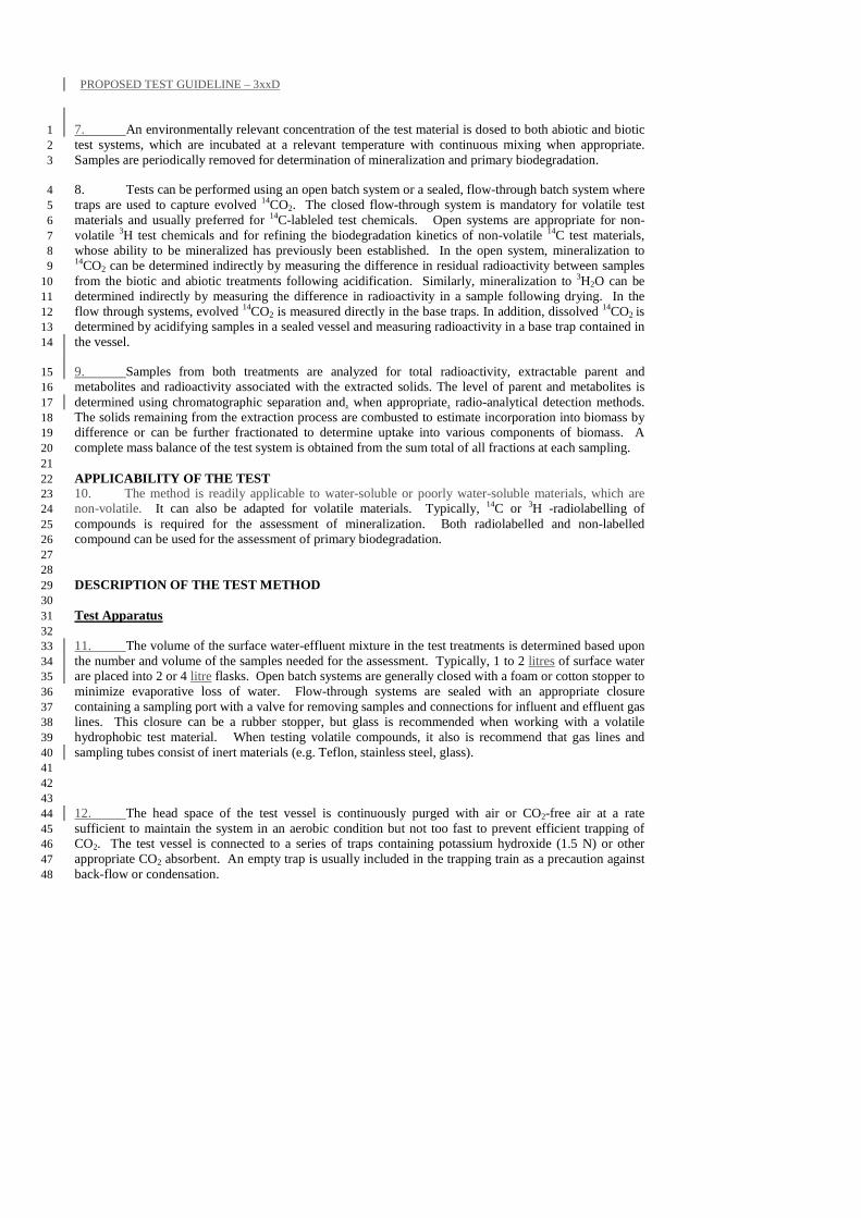
PROPOSED TEST GUIDELINE – 3xxD
7. An environmentally relevant concentration of the test material is dosed to both abiotic and biotic 1 test systems, which are incubated at a relevant temperature with continuous mixing when appropriate. 2 Samples are periodically removed for determination of mineralization and primary biodegradation. 3
8. Tests can be performed using an open batch system or a sealed, flow-through batch system where 4 traps are used to capture evolved 14CO2. The closed flow-through system is mandatory for volatile test 5 materials and usually preferred for 14C-lableled test chemicals. Open systems are appropriate for non-6 volatile 3H test chemicals and for refining the biodegradation kinetics of non-volatile 14C test materials, 7 whose ability to be mineralized has previously been established. In the open system, mineralization to 8 14CO2 can be determined indirectly by measuring the difference in residual radioactivity between samples 9 from the biotic and abiotic treatments following acidification. Similarly, mineralization to 3H2O can be 10 determined indirectly by measuring the difference in radioactivity in a sample following drying. In the 11 flow through systems, evolved 14CO2 is measured directly in the base traps. In addition, dissolved 14CO2 is 12 determined by acidifying samples in a sealed vessel and measuring radioactivity in a base trap contained in 13 the vessel. 14
9. Samples from both treatments are analyzed for total radioactivity, extractable parent and 15 metabolites and radioactivity associated with the extracted solids. The level of parent and metabolites is 16 determined using chromatographic separation and, when appropriate, radio-analytical detection methods. 17 The solids remaining from the extraction process are combusted to estimate incorporation into biomass by 18 difference or can be further fractionated to determine uptake into various components of biomass. A 19 complete mass balance of the test system is obtained from the sum total of all fractions at each sampling. 20 21 APPLICABILITY OF THE TEST 22 10. The method is readily applicable to water-soluble or poorly water-soluble materials, which are 23 non-volatile. It can also be adapted for volatile materials. Typically, 14C or 3H -radiolabelling of 24 compounds is required for the assessment of mineralization. Both radiolabelled and non-labelled 25 compound can be used for the assessment of primary biodegradation. 26 27 28 DESCRIPTION OF THE TEST METHOD 29 30 Test Apparatus 31 32 11. The volume of the surface water-effluent mixture in the test treatments is determined based upon 33 the number and volume of the samples needed for the assessment. Typically, 1 to 2 litres of surface water 34 are placed into 2 or 4 litre flasks. Open batch systems are generally closed with a foam or cotton stopper to 35 minimize evaporative loss of water. Flow-through systems are sealed with an appropriate closure 36 containing a sampling port with a valve for removing samples and connections for influent and effluent gas 37 lines. This closure can be a rubber stopper, but glass is recommended when working with a volatile 38 hydrophobic test material. When testing volatile compounds, it also is recommend that gas lines and 39 sampling tubes consist of inert materials (e.g. Teflon, stainless steel, glass). 40 41 42 43 12. The head space of the test vessel is continuously purged with air or CO2-free air at a rate 44 sufficient to maintain the system in an aerobic condition but not too fast to prevent efficient trapping of 45 CO2. The test vessel is connected to a series of traps containing potassium hydroxide (1.5 N) or other 46 appropriate CO2 absorbent. An empty trap is usually included in the trapping train as a precaution against 47 back-flow or condensation. 48
PROPOSED TEST GUIDELINE – 3xxD
Last saved by huet_m 05/11/2007 35
Equipment 1 2
13. The following standard laboratory equipment are used: 3 4 - miscellaneous glassware and pipettes; 5 - magnetic stirrers or shaker for continuous mixing of the test flasks; 6 - centrifuge; 7 - pH meter; 8 - solid CO2 (dry ice)/acetone or liquid nitrogen bath; 9 - freeze dryer (lyophilizer); 10 - oven or microwave oven for dry weight determinations; 11 - membrane filtration apparatus; 12 - autoclave; 13 - facilities to handle radiolabelled substances; 14 - equipment to quantify 14C and 3H in liquid samples and solid samples (e.g. liquid scintillation 15
counter LSC); 16 - equipment to quantify 14C and 3H in solid samples (e.g. sample oxidizer); 17 - equipment to trap volatilized 14C and 3H from gas trapping system (in-line activated 18
charcoal trap or equivalent); 19 - equipment for thin layer chromatography (TLC) or high performance liquid chromatography 20
(HPLC); 21 - equipment to quantify 14C and 3H for TLC (scanner) or HPLC (in-line detector); 22 - analytical equipment for the determination of the test (and reference) substance if specific 23
chemical analysis is used (e.g. gas chromatograph, high performance liquid chromatograph, 24 mass spectrometer). 25
26
Selection of Environmental Samples 27
14. The source of surface water, activated sludge or effluent should be consistent with the objective 28 of the simulation test. For a site-specific assessment, activated sludge or effluent should be obtained from 29 the specific wastewater treatment plant in question. Likewise, the surface water should be obtained 30 upstream from that treatment plant outfall. The ratio of these components should be chosen to simulate a 31 specific flow scenario (e.g. low flow or mean flow). Alternatively, if hydraulic conditions below the 32 outfall are known, the test system can consist simply of samples obtained downstream from the outflow. 33 However, such conditions are variable and hard to reproduce. 34
15. For a generic assessment activated sludge or effluent should be obtained from a typical 35 wastewater treatment plant receiving predominantly domestic wastewater. Likewise, the surface water 36 should be typical of surface waters into which effluent is released. If the chemical is currently a 37 component of wastewater entering the wastewater treatment facility or is episodically released to 38 wastewater, freshly collected activated sludge or effluent will be ideal for the test. WWTP effluent 39 consists of activated sludge liquor and biosolids, but it can be variable in its solids level and impacted by 40 chlorination or other processes. The best method of simulating this scenario is using filtered effluent and 41 surface water combined at the targeted dilution ratio and separately adding activated sludge biosolids at a 42 targeted concentration. If the effluent is difficult to obtain, the activated sludge can be filtered or 43 centrifuged to remove biosolids, and the liquor and biosolids can then be added at a defined ratio to the 44 test. For a generic assessment, the European Technical Guidance Document assumes effluent containing 45 30 mg/L of biosolids is diluted 10-fold into surface water containing 15 mg/L of suspended solids (22). 46 Hence, 3 mg of biosolids in 100 ml of filtered effluent or activated sludge liquor and 900 ml of surface 47 water approximates this generic scenario. An additional scenario with 10 mg of biosolids and 330 ml of 48
PROPOSED TEST GUIDELINE – 3xxD
filtered effluent or liquor per litre also might be considered to simulate critical low flow conditions that 1 might occur during dry seasons. 2
16. For a new chemical, which will be continuously released to wastewater, the activated sludge or 3 effluent ideally should be obtained from a laboratory scale treatment system such as a porous pot or CAS 4 [OECD 303A] (2), which has been fed wastewater amended with unlabelled test material. The source of 5 the starting sludge, wastewater (influent) and the operating conditions (influent concentration, hydraulic 6 retention time, solids retention time) for the laboratory unit should accurately reflect site-specific or 7 generic conditions. In the case of the latter, the European Technical Guidance Document (22) specifies an 8 HRT of 6.9 hours and an SRT of 9.2 days in its generic scenario for wastewater treatment. The European 9 Technical Guidance Document also provides guidance on estimating wastewater concentration based upon 10 expected usage volumes. In general, steady state will be reached within 2 to 3 SRTs after which point the 11 biosolids or effluent can be used for testing. 12 13 Collection, Transport and Storage of Environmental Samples 14 15 17. The activated sludge should be collected from a well mixed region of the aeration basin, the 16 effluent should be collected from the discharge point of the WWTP. Surface water should be collected 17 from a site with known inputs of wastewater. The temperature of the samples should be noted at collection. 18 Collection containers should allow for adequate ventilation and measures should be taken to prevent the 19 temperature of the sample from significantly exceeding the temperature used in the test. The samples are 20 typically stored at test temperature with continuous aeration. Samples should not be stored frozen. 21 22 Preparation of Test Treatments 23 24 18. The surface water should be characterized by measuring the total suspended solids (TSS), total 25 hardness and pH. A standard plate count and organic carbon analysis are optional. When using activated 26 sludge to represent WWTP effluent, the MLSS is sieved through a 2mm screen, blended (optional) and 27 allowed to settle. The TSS concentration of the liquor is measured. The liquor is added to the surface 28 water at a volume sufficient to achieve the targeted biosolids concentration. If more volume is needed to 29 reach the targeted dilution ratio in the test, filtered or centrifuged activated sludge liquor is added to reach 30 the necessary dilution. If using treated effluent and a targeted activated sludge biosolids concentration, the 31 effluent is filtered and mixed with the surface water at the targeted dilution ratio. The MLSS is prepared as 32 described previously. The pH and TSS of the prepared surface water mixture should be measured. An 33 optional standard plate count and organic carbon analysis can also be performed. 34 35
19. The preparation of the abiotic treatment is typically performed using a combination of chemical 36 and heat sterilization. A proven approach is to add mercuric chloride solution (0.1 g/L) to the mixture, 37 which is then autoclaved for at least 90 minutes. After cooling, the pH of the abiotic treatment should be 38 measured and adjusted to match that of the biologically active treatment. Alternative approaches to 39 deactivate the surface water mixture can also be used. 40 41 Test Substance Preparation 42 43 20. Ideally, distilled water should be used to prepare stock solutions of the test and reference 44 substances. When appropriate, an alternative method may be used to solubilize or disperse the test 45 chemical in a manner consistent with its normal entry into the environment. Water miscible non-toxic 46 solvents may be used when necessary, but attention should be paid to the associated organic load involved 47 with adding organic solvents. Alternatively, the sample may be added in a neat form to the test system in 48 a manner that maximizes its even and rapid distribution into the test treatments. For materials which are 49 poorly soluble and typically associated with suspended solids in effluent, it may be appropriate to adsorb 50
PROPOSED TEST GUIDELINE – 3xxD
Last saved by huet_m 05/11/2007 37
the test material onto an inert solid carrier, which is then dosed to the test system. If the test material can 1 not be evenly distributed within the test system prior to the initial sampling point, individual test systems 2 can be prepared that are destructively sampled at each sampling interval. 3 4 5 21. The volume of added stock should be of sufficient capacity to ensure rapid and even distribution 6 of the test material in the treatment and accurate administration of the dose between like treatments. 7 Ideally, when dosing with aqueous solutions, the added volume should be > 2 ml; for non-toxic solvents, 8 < 0.1 ml/ L. If appropriate, dosing solutions may be prepared in advance and refrigerated. The activity of 9 the stock should be checked by LSC. 10 11 Test conditions 12 13 Test temperature 14 15 22. Incubation should take place in the dark (preferred) or in diffuse light at a controlled temperature, 16 which may be the field temperature or a standard laboratory temperature of 20-25°C. 17 18 Agitation 19 20 23. To keep the test medium in suspension, the test systems are agitated by means of continuous 21 shaking or stirring. Agitation also facilitates oxygen transfer from the headspace to the liquid so that 22 aerobic conditions can be adequately maintained. 23 24 Test duration 25 26 24. The duration of the test should be sufficiently long to assess the biodegradation of the test 27 chemical during its normal residence time within the WWTP effluent-surface water mixing zone. 28 Normally, the test period will last 28 days. However, it may be extended longer to obtain additional data 29 points to estimate kinetic constants or to assess the completeness of degradation under the conditions 30 within the test. Conversely, it may be ended before this time if degradation has plateaued. 31 32 Number of test vessels 33 34 25. At a minimum, there should be a single abiotic and a single biotic test vessel for each test 35 material concentration. While replicates can be prepared for each treatment, more useful kinetic 36 information usually can be gained by increasing the number of time points sampled within a treatment. 37 38 PROCEDURE 39 40 Dosing 41 42 26. At test initiation, the test vessel is opened and the test material is quantitatively added directly to 43 the treatment with constant mixing. It is recommended that the dose be administered in a gradual fashion 44 below the air-water interface, to ensure uniform distribution of the test material into the test medium. The 45 biotic and abiotic treatments are dosed in an identical manner. Generally, the biotic systems are dosed 46 first, followed by the abiotic systems. Exact timing is typically more critical for the biotic versus the 47 abiotic treatments for kinetic analyses. 48 49 Sampling Schedule 50 51
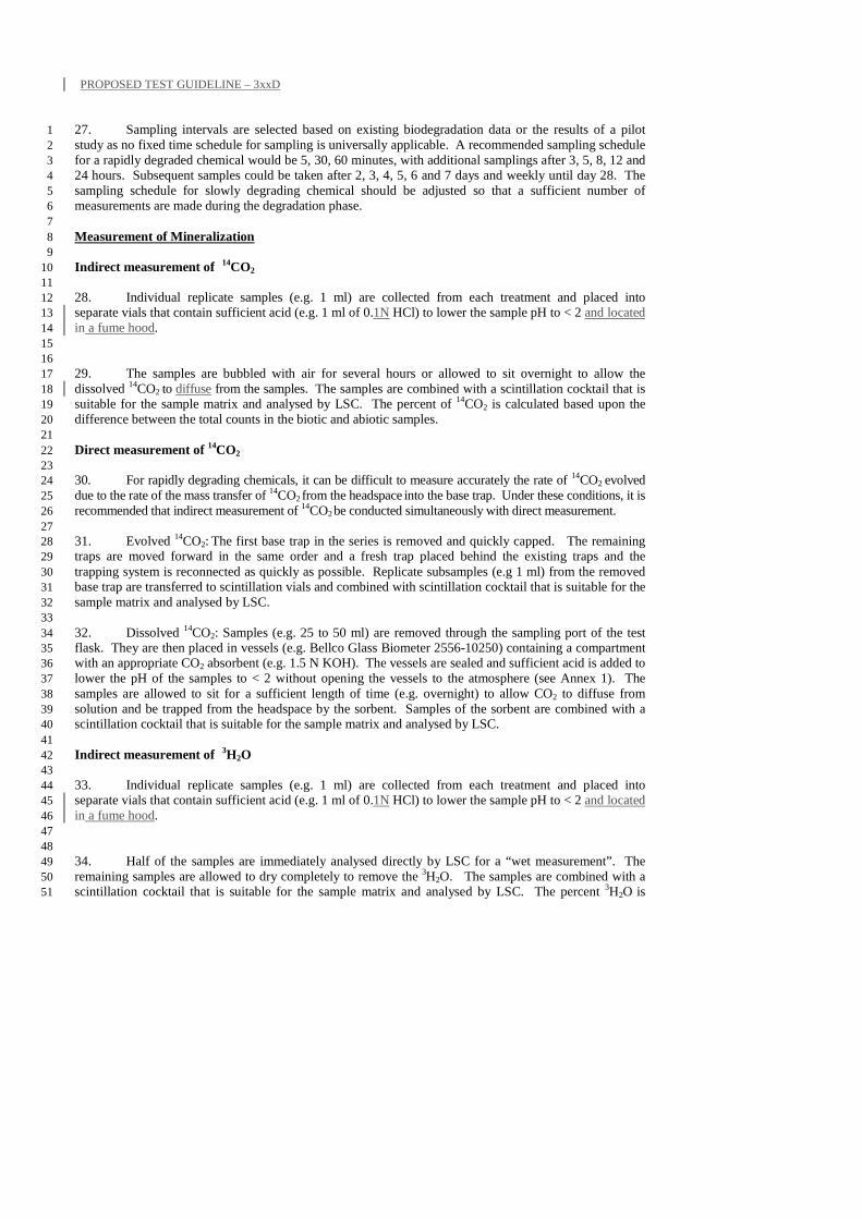
PROPOSED TEST GUIDELINE – 3xxD
27. Sampling intervals are selected based on existing biodegradation data or the results of a pilot 1 study as no fixed time schedule for sampling is universally applicable. A recommended sampling schedule 2 for a rapidly degraded chemical would be 5, 30, 60 minutes, with additional samplings after 3, 5, 8, 12 and 3 24 hours. Subsequent samples could be taken after 2, 3, 4, 5, 6 and 7 days and weekly until day 28. The 4 sampling schedule for slowly degrading chemical should be adjusted so that a sufficient number of 5 measurements are made during the degradation phase. 6 7 Measurement of Mineralization 8 9 Indirect measurement of 14CO2 10 11 28. Individual replicate samples (e.g. 1 ml) are collected from each treatment and placed into 12 separate vials that contain sufficient acid (e.g. 1 ml of 0.1N HCl) to lower the sample pH to < 2 and located 13 in a fume hood. 14 15 16 29. The samples are bubbled with air for several hours or allowed to sit overnight to allow the 17 dissolved 14CO2 to diffuse from the samples. The samples are combined with a scintillation cocktail that is 18 suitable for the sample matrix and analysed by LSC. The percent of 14CO2 is calculated based upon the 19 difference between the total counts in the biotic and abiotic samples. 20 21 Direct measurement of 14CO2 22 23 30. For rapidly degrading chemicals, it can be difficult to measure accurately the rate of 14CO2 evolved 24 due to the rate of the mass transfer of 14CO2 from the headspace into the base trap. Under these conditions, it is 25 recommended that indirect measurement of 14CO2 be conducted simultaneously with direct measurement. 26 27 31. Evolved 14CO2:
The first base trap in the series is removed and quickly capped. The remaining 28 traps are moved forward in the same order and a fresh trap placed behind the existing traps and the 29 trapping system is reconnected as quickly as possible. Replicate subsamples (e.g 1 ml) from the removed 30 base trap are transferred to scintillation vials and combined with scintillation cocktail that is suitable for the 31 sample matrix and analysed by LSC. 32 33 32. Dissolved 14CO2: Samples (e.g. 25 to 50 ml) are removed through the sampling port of the test 34 flask. They are then placed in vessels (e.g. Bellco Glass Biometer 2556-10250) containing a compartment 35 with an appropriate CO2 absorbent (e.g. 1.5 N KOH). The vessels are sealed and sufficient acid is added to 36 lower the pH of the samples to < 2 without opening the vessels to the atmosphere (see Annex 1). The 37 samples are allowed to sit for a sufficient length of time (e.g. overnight) to allow CO2 to diffuse from 38 solution and be trapped from the headspace by the sorbent. Samples of the sorbent are combined with a 39 scintillation cocktail that is suitable for the sample matrix and analysed by LSC. 40 41 Indirect measurement of 3H2O 42 43 33. Individual replicate samples (e.g. 1 ml) are collected from each treatment and placed into 44 separate vials that contain sufficient acid (e.g. 1 ml of 0.1N HCl) to lower the sample pH to < 2 and located 45 in a fume hood. 46 47 48 34. Half of the samples are immediately analysed directly by LSC for a “wet measurement”. The 49 remaining samples are allowed to dry completely to remove the 3H2O. The samples are combined with a 50 scintillation cocktail that is suitable for the sample matrix and analysed by LSC. The percent 3H2O is 51
PROPOSED TEST GUIDELINE – 3xxD
Last saved by huet_m 05/11/2007 39
calculated based upon the difference between the total counts in the wet and dry samples and the initial 1 level of radioactivity dosed to the samples. 2 3 Measurement of Radioactivity in Treatment 4 5
35. Small volume samples (e.g. 1 ml) are analysed directly by LSC to quantify the radioactivity 6 remaining in each treatment over time. These measurements are used to confirm that the recovery of 7 radioactivity from the extracted samples is acceptable and to monitor for volatilization. 8 9 Measurement of Parent and Metabolites 10 11 Extraction 12 13 36. A sample is collected from both the abiotic and biotic treatments. The sample volume is 14 typically > 25 ml. However, the size will depend on the test concentration, specific activity and the 15 sensitivity of the analytical procedures. 16 17 37. Various approaches can be used for concentrating and extracting the samples. A proven 18 approach for nonvolatile test chemicals involves flash freezing the samples, followed by lyophilization and 19 extraction of the dried residue with appropriate solvent(s) for parent and metabolites. Flash freezing 20 quickly stops biological activity without hydrolyzing or otherwise altering labile test materials. The extract 21 is filtered to recover the solvent and solids separately. The filter must be compatible with the solvent type 22 (e.g. aqueous or non-aqueous). The resulting extracts can be concentrated through evaporation and the 23 total radioactivity in each extract is determined by LSC. 24 25 38. For volatile test materials, the sample can be passed through a filter and solid phase extraction 26 (SPE) column or SPE disk placed in tandem, which are subsequently eluted with appropriate solvents to 27 recover parent and metabolites. Alternatively, the aqueous samples can be extracted with an appropriate 28 solvent system and then filtered to recover biomass solids, assuming sufficient extraction efficiency. The 29 total radioactivity in all extracts is determined by LSC. Care must be taken in concentrating extracts 30 containing volatile test materials or metabolites. 31 32 39. Other approaches can be utilized, but with all approaches it is important to document recoveries 33 and consider the time involved in terminating biological activity and factor it into the sample times used 34 for kinetic analyses. 35 36 Analysis of Parent and Metabolites 37 38 40. The relative abundance of parent and metabolites within the extracts can be determined using thin 39 layer chromatography (TLC), high performance liquid chromatography (HPLC) or other separation 40 techniques with radioactivity detection. 41 42 41. If sensitive specific analytical methods are available, primary biodegradation can be assessed by 43 measuring the total residual concentration of test substances and metabolites instead of using radioisotope 44 techniques. 45 46 Characterization of Metabolites 47 48 42. Whenever possible, the chromatographic behaviour of unknown peaks should be compared to 49 that of predicted metabolites, if authentic standards exist. Usually, the quantity and purity of metabolites 50 generated in this test make definitive identification by other direct means impossible. Depending upon 51
Deleted: benchmark
PROPOSED TEST GUIDELINE – 3xxD
chromatographic behaviour, it is usually possible to determine if a metabolite is more or less polar than the 1 parent. This information combined with known biochemical reactions along with when a metabolite 2 appears and disappears in the sequence of biodegradation can form an additional basis for inferring its 3 identity. If necessary, the Kow of major metabolites can be determined by HPLC (e.g. [OECD 117] (24)) 4 using an on-line radioactivity detector. 5 6 Measurement of Extracted Solids 7 8 43. Since the filters will retain carbonate salts as well as microorganisms from the test system, the 9 filter containing the biosolids is placed into a scintillation vial and acidified to pH <2 by submerging it in a 10 weak acid solution (1 ml of 0.1N HCl). The samples are allowed to sit for sufficient time (e.g. overnight) 11 for the dissolved 14CO2 to diffuse from the samples. The samples are combined with a scintillation cocktail 12 that is suitable for the sample matrix and analysed by LSC. The level of radioactivity in the biotic solids 13 above that in solids from the abiotic control typically represents incorporation of radioactivity into 14 biomass. 15 16 Measurement of Volatilized Radioactivity 17 18 44. For volatile test materials, the volatile traps are extracted with appropriate solvents and the 19 radioactivity in the extracts is analyzed by LSC. The relative abundance of parent and metabolites in the 20 extract(s) can be determined as described above. 21 22
PROPOSED TEST GUIDELINE – 3xxE
Last saved by huet_m 05/11/2007 41
3xxE BIODEGRADATION IN UNTREATED WASTEWATER-SURFACE WATER 1 MIXING ZONE 2 3 INTRODUCTION 4
1. In developing regions lacking wastewater treatment infrastructure, it is common for wastewater 5 to be directly discharged to surface waters. This test is designed to simulate these situations and evaluate 6 the biodegradation of a chemical that is discharged to surface water as a component of untreated 7 wastewater. It is useful for determining the extent of biodegradation as well as rates of primary and 8 ultimate biodegradation under such direct discharge conditions. The results can be used to estimate the 9 reduction in chemical concentration resulting from biodegradation as a volume of water moves 10 downstream from a wastewater outfall. As an option, this reduction can be compared against the decreases 11 in other wastewater components such as biochemical oxygen demand (BOD), chemical oxygen demand 12 (COD) or total organic carbon (TOC). The test system consists of freshly collected wastewater and surface 13 water. The usefulness of the measured rates for accurately predicting downstream exposure will be a 14 function of the fidelity of the simulation to actual conditions in the mixing zone. Along with test material 15 concentration, factors to consider in designing this test include dissolved oxygen concentration and the 16 degree to which effluent is diluted into surface water. 17
2. For existing chemicals consistently present in wastewater, freshly collected wastewater and 18 surface water incubated with a tracer level of radiolabelled test chemical will provide the most realistic 19 kinetic parameters regarding the current chemical load. For chemicals not consistently present in 20 wastewater, sufficient test chemical (radiolabelled and unlabelled) should be added to approximate the 21 expected concentration in wastewater diluted into surface water during an episodic release or following 22 commercialization of a new chemical. Approaches for estimating such an expected wastewater 23 concentration can be found in Holman (21) and the European Technical Guidance Document (22). 24
3. For low dilution situations, it is best to incubate the mixtures under reduced dissolved oxygen 25 conditions (1 – 4 mg/L) to simulate the DO below a wastewater outfall. In this test, the chemical and its 26 degrader populations usually are not in steady state and the observed kinetics will be quasi first-order, or 27 second-order Monod. 28
4. The test can be done using a single or two phase design. In the former, biodegradation is 29 evaluated in wastewater, which has been diluted into a given clean or wastewater impacted surface water. 30 In the latter, biodegradation is assessed in wastewater, which has been sequentially diluted into clean and 31 wastewater impacted surface waters. In this test design, the test chemical is dosed into wastewater diluted 32 into clean surface water and disappearance of test chemical and conventional pollutants (BOD, COD, etc) 33 are monitored with time (phase 1). Subsequently, a second dose of test chemical and wastewater is added 34 to the same system to simulate dilution of wastewater into surface water previously polluted by wastewater 35 (phase 2). 36 37 GENERAL TEST PROCEDURE 38
5. The test chemical is incubated with abiotic and biotic mixtures of wastewater and surface water 39 usually under reduced dissolved oxygen (DO) conditions (1 – 4 mg/L) over a period of time. The ratio of 40 these components is based upon specific or generic scenarios for release of wastewater to surface water. 41 Biological activity is inhibited in the abiotic control, which is used for estimating mineralization by 42 difference, establishing extraction efficiency and recovery of the parent molecule and quantifying other 43 loss processes, such as hydrolysis, oxidation, volatilization or sorption to test apparatus. 44
6. If an analytical method with the required sensitivity is identified, the rate of parent degradation or 45
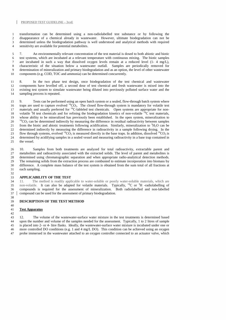
PROPOSED TEST GUIDELINE – 3xxE
transformation can be determined using a non-radiolabelled test substance or by following the 1 disappearance of a chemical already in wastewater. However, ultimate biodegradation can not be 2 determined unless the biodegradation pathway is well understood and analytical methods with required 3 sensitivity are available for potential metabolites. 4
7. An environmentally relevant concentration of the test material is dosed to both abiotic and biotic 5 test systems, which are incubated at a relevant temperature with continuous mixing. The biotic samples 6 are incubated in such a way that dissolved oxygen levels remain at a reduced level (1- 4 mg/L), 7 characteristic of the situation below a wastewater outfall. Samples are periodically removed for 8 determination of mineralization and primary biodegradation and as an option, the level of other wastewater 9 components (e.g. COD, TOC and ammonia) can be determined concurrently. 10
8. In the two phase test design, once biodegradation of the test chemical and wastewater 11 components have levelled off, a second dose of test chemical and fresh wastewater is mixed into the 12 existing test system to simulate wastewater being diluted into previously polluted surface water and the 13 sampling process is repeated. 14
9. Tests can be performed using an open batch system or a sealed, flow-through batch system where 15 traps are used to capture evolved 14CO2. The closed flow-through system is mandatory for volatile test 16 materials and usually preferred for 14C-lableled test chemicals. Open systems are appropriate for non-17 volatile 3H test chemicals and for refining the biodegradation kinetics of non-volatile 14C test materials, 18 whose ability to be mineralized has previously been established. In the open system, mineralization to 19 14CO2 can be determined indirectly by measuring the difference in residual radioactivity between samples 20 from the biotic and abiotic treatments following acidification. Similarly, mineralization to 3H2O can be 21 determined indirectly by measuring the difference in radioactivity in a sample following drying. In the 22 flow through systems, evolved 14CO2 is measured directly in the base traps. In addition, dissolved 14CO2 is 23 determined by acidifying samples in a sealed vessel and measuring radioactivity in a base trap contained in 24 the vessel. 25
10. Samples from both treatments are analyzed for total radioactivity, extractable parent and 26 metabolites and radioactivity associated with the extracted solids. The level of parent and metabolites is 27 determined using chromatographic separation and when appropriate radio-analytical detection methods. 28 The remaining solids from the extraction process are combusted to estimate incorporation into biomass by 29 difference. A complete mass balance of the test system is obtained from the sum total of all fractions at 30 each sampling. 31 32 APPLICABILITY OF THE TEST 33 11. The method is readily applicable to water-soluble or poorly water-soluble materials, which are 34 non-volatile. It can also be adapted for volatile materials. Typically, 14C or 3H -radiolabelling of 35 compounds is required for the assessment of mineralization. Both radiolabelled and non-labelled 36 compound can be used for the assessment of primary biodegradation. 37
38 DESCRIPTION OF THE TEST METHOD 39 40 Test Apparatus 41 42 12. The volume of the wastewater-surface water mixture in the test treatments is determined based 43 upon the number and volume of the samples needed for the assessment. Typically, 1 to 2 litres of sample 44 is placed into 2- or 4- litre flasks. Ideally, the wastewater-surface water mixture is incubated under one or 45 more controlled DO conditions (e.g. 1 and 4 mg/L DO). This condition can be achieved using an oxygen 46 probe immersed in the wastewater attached to an oxygen controller connected to an actuator valve, which 47
PROPOSED TEST GUIDELINE – 3xxE
Last saved by huet_m 05/11/2007 43
controls the aeration of the wastewater (see Annex 1). This aeration is balanced against continuous 1 sparging with nitrogen to achieve the targeted DO level. Alternatively, the wastewater can be incubated 2 with stirring but minimum aeration to keep DO levels at desired levels, nitrogen or air can be added 3 periodically to maintain DO level. In this case, DO readings should be reported at regular intervals. 4 5 13. Open systems are generally closed with a foam or cotton stopper to minimize evaporative loss of 6 water. Flow-through systems are sealed with an appropriate closure containing a sampling port with a 7 valve for removing samples and connections for influent and effluent gas lines. This closure can be a 8 rubber stopper, but glass is recommended when working with a volatile hydrophobic test material. When 9 testing volatile compounds, it also is recommend that gas lines and sampling tubes consist of inert 10 materials (e.g. Teflon, stainless steel, glass). 11 12 14. The head space of the test vessel is continuously purged with air or CO2-free air at a rate 13 sufficient to maintain the system in an aerobic condition but not too fast to prevent efficient trapping of 14 CO2. The test vessel is connected to a series of traps containing potassium hydroxide (1.5 N) or other 15 appropriate CO2 absorbent. An empty trap is usually included and positioned in front of the absorbent in 16 the trapping train as a precaution against back-flow or condensation. 17 18 Equipment 19 20
- miscellaneous glassware and pipettes; 21 - magnetic stirrers or shaker for continuous mixing of the test flasks; 22 - centrifuge; 23 - pH meter; 24 - solid CO2 (dry ice)/acetone or liquid nitrogen bath; 25 - freeze dryer (lyophilizer); 26 - oven or microwave oven for dry weight determinations; 27 - membrane filtration apparatus; 28 - autoclave; 29 - facilities to handle radiolabelled substances; 30 - equipment to quantify 14C and 3H in liquid samples and solid samples (e.g. liquid scintillation 31
counter LSC); 32 - equipment to quantify 14C and 3H in solid samples (e.g. sample oxidizer); 33 - equipment to trap volatilized 14C and 3H from gas trapping system (in-line activated charcoal 34
trap or equivalent); 35 - equipment for thin layer chromatography (TLC) or high performance liquid chromatography 36
(HPLC); 37 - equipment to quantify 14C and 3H for TLC (scanner) or HPLC (in-line detector); 38 - analytical equipment for the determination of the test (and reference) substance if specific 39
chemical analysis is used (e.g. gas chromatograph, high performance liquid chromatograph, 40 mass spectrometer). 41
42 15.. The following laboratory equipment is not essential but useful: 43
44 - oxygen meter 45 - oxygen controller with probe and actuator valve. 46 - COD digestion vials 47 - Nitrogen ammonia reagent set 48 - Spectrophotometer 49
Selection of Environmental Samples 50
PROPOSED TEST GUIDELINE – 3xxE
16. The source of wastewater and surface water should be consistent with the objective of the 1 simulation test. For a site specific assessment, the wastewater should be obtained from the specific sewer 2 system in question and the surface water should be obtained upstream from the wastewater outfall. The 3 ratio of these components should be chosen to simulate a specific flow scenario (e.g. low flow or mean 4 flow). Alternatively, if hydraulic conditions below the outfall are known, the test system can consist 5 simply of samples obtained downstream from the outflow. However, such conditions are variable and hard 6 to reproduce. 7
17. For a generic assessment wastewater samples should be predominantly derived from domestic 8 sources, and the surface water should be typical of surface waters into which wastewater is released. 9 Although difficult to duplicate in practice, the European Technical Guidance Document uses 450 mg/L of 10 suspended solids and 270 mg/L of BOD (biological oxygen demand) as default levels in wastewater (22). 11 In North America, typical wastewaters contain from 100 to 350 mg/L of suspended solids and 110 to 400 12 mg/L of BOD (23). 13 14 Collection, Transport and Storage of Environmental Samples 15 16 18. The wastewater should be collected from a sewer access point or at the head of a wastewater 17 treatment plant. The temperature of the sample should be noted at collection. During transport, the 18 temperature of the sample should not significantly exceed the temperature used in the test. The wastewater 19 is typically stored at test temperature with low mixing. No samples should ever be stored frozen. 20 21 19. Surface water should be collected from a site with known inputs of wastewater. The temperature 22 of the samples should be noted at collection. During transport, the temperature of the samples should not 23 significantly exceed the temperature used in the test. The surface water is typically stored at test 24 temperature with continuous aeration. No samples should ever be stored frozen. 25 26 Preparation of Test Treatments 27 28 29 20. The freshly collected wastewater should be largely free from coarse particles. Total suspended 30 solids (TSS), pH and chemical oxygen demand (COD) should be determined for the wastewater. NH3, 31 organic carbon and standard plate count are optional analysis. The surface water should be characterized 32 by measuring the total suspended solids (TSS), total hardness and pH. A standard plate count and 33 organic carbon analysis are optional. The wastewater is added to the surface water at a volume sufficient 34 to achieve the targeted dilution of wastewater into surface water. The pH, COD, and TSS of the prepared 35 surface water mixture should be measured. An optional standard place count, NH3 and organic carbon 36 analysis can also be performed on the mixture. 37 38 21. The preparation of the abiotic treatment is typically performed using a combination of chemical 39 and heat sterilization. A proven approach is to add mercuric chloride (HgCl2 = 0.1 g/L) to the mixture, 40 which is then autoclaved for at least 90 minutes. After cooling, the pH of the abiotic treatment should be 41 measured and adjusted to match that of the biologically active treatment. Alternative approaches to 42 deactivate the surface water mixture can also be used. 43 44 Test Substance Preparation 45 46 22. Ideally, distilled water should be used to prepare stock solutions of the test and reference 47 substances. When appropriate, an alternative method may be used to solubilize or disperse the test 48 chemical in a manner consistent with its normal entry into the environment. Water-miscible non-toxic 49 solvents may be used when necessary, but attention should be paid to the associated organic load involved 50
PROPOSED TEST GUIDELINE – 3xxE
Last saved by huet_m 05/11/2007 45
with adding organic solvents. Alternatively, the sample may be added in a neat form to the test system in 1 a manner that maximizes its even and rapid distribution into the test treatments. For materials which are 2 poorly soluble and typically associated with suspended solids in wastewater, it may be appropriate to 3 adsorb the test material onto an inert solid carrier, which is then dosed to the test system. If the test 4 material can not be evenly distributed within the test system prior to the initial sampling point, individual 5 test systems can be prepared that are destructively sampled at each sampling interval. 6 7 8 23. The volume of added stock should be of sufficient capacity to ensure rapid and even distribution 9 of the test material in the treatment and accurate administration of the dose between like treatments. 10 Ideally, when dosing with aqueous solutions, the added volume should be > 2 ml; for non-toxic solvents, 11 < 0.1 ml/L. If appropriate, dosing solutions may be prepared in advance and refrigerated. The activity of 12 the stock should be checked by LSC. 13 14 Test conditions 15 16 Test temperature 17 18 24. Incubation should take place in the dark (preferred) or in diffuse light at a controlled temperature, 19 which may be the field temperature or a standard laboratory temperature of 20-25°C. 20 21 Agitation 22 23 25. To keep the solids in suspension, the test vessels are minimally agitated by means of continuous 24 mixing or stirring. 25 26 Test duration 27 28 26. The duration of the test should be sufficiently long to assess the biodegradation of the test 29 chemical during its normal residence time within the wastewater-surface water mixing zone. Normally, the 30 test period will last 28 days. However, it may be extended longer to obtain additional data points to 31 estimate kinetic constants or to assess the completeness of degradation under the conditions within the test. 32 Conversely, it may be ended before this time if degradation has plateaued. 33 34 Number of test vessels 35 36 27. At a minimum, there should be a single abiotic and a single biotic test vessel for each test 37 material and test material concentration. While replicates can be prepared for each treatment, more useful 38 kinetic information usually can be gained by increasing the number of time points sampled within a 39 treatment. 40 41
PROCEDURE 42 43 Dosing 44 45 28. At test initiation, the test vessel closure is removed and the test material is quantitatively added 46 directly to the treatment with constant mixing. It is recommended that the dose be administered in a 47 gradual fashion below the air-water interface, to ensure uniform distribution of the test material into the 48 wastewater. The biotic and abiotic treatments are dosed in an identical manner. Generally, the biotic 49 systems are dosed first, followed by the abiotic systems. Exact timing is typically more critical for the 50 biotic versus the abiotic treatments for kinetic analyses. 51
PROPOSED TEST GUIDELINE – 3xxE
1 Sampling Schedule 2 3 29. Sampling intervals are selected based on existing biodegradation data or the results of a pilot 4 study as no fixed time schedule for sampling is universally applicable. A recommended sampling schedule 5 for a rapidly degraded chemical would be 15, 30 and 60 minutes, with additional samplings after 2, 5, 8, 12 6 and 24 hours and day 2, 3 and 7 and weekly thereafter. The sampling schedule for slowly degrading 7 chemicals should be adjusted so that a sufficient number of measurements are made during the degradation 8 phase. 9 10
Measurement of Mineralization 11 12 Indirect measurement of 14CO2 13 14 30. Individual replicate samples (e.g. 1 ml) are collected from each treatment and placed into 15 separate vials that contain sufficient acid (e.g. 1 ml of 0.1N HCl) to lower the sample pH to < 2 and located 16 in a fume hood. 17 . 18 19 31. The samples are bubbled with air for several hours or allowed to sit overnight to allow the 20 dissolved 14CO2 to diffuse from the samples. The samples are combined with a scintillation cocktail that is 21 suitable for the sample matrix and analysed by LSC. The percent of 14CO2 is calculated based upon the 22 difference between the total counts in the biotic and abiotic samples. 23 24 Direct measurement of 14CO2 25 26 32. Evolved 14CO2:
The first base trap in the series is removed and quickly capped. The remaining 27 traps are moved forward in the same order and a fresh trap placed behind the existing traps and the 28 trapping system reconnected as quickly as possible. Replicate subsamples (e.g. 1 ml) from the base trap 29 are removed and transferred to scintillation vials and combined with a scintillation cocktail that suitable for 30 the sample matrix and analysed by LSC. 31 32 33. Dissolved 14CO2: Samples (e.g. 10 to 25 ml) are removed through the sampling port of the test 33 flask. They are then placed in vessels (e.g. Bellco Glass Biometer 2556-10250) containing a compartment 34 with an appropriate CO2 absorbent (e.g. 1.5 N KOH). The vessels are sealed and sufficient acid is added to 35 lower the pH of the samples to < 2 without opening the vessels to the atmosphere (see Annex 1). The 36 samples are allowed to sit for a sufficient length of time (e.g. overnight) to allow CO2 to diffuse from 37 solution and be trapped from the headspace by the sorbent. Samples of the sorbent are combined with a 38 scintillation cocktail that is suitable for the sample matrix and analysed by LSC. 39 40 Indirect measurement of 3H2O 41 42 34 Individual replicate samples (e.g. 1 ml) are collected from each treatment and placed into 43 separate vials that contain sufficient acid (e.g. 1 ml of 0.1N HCl) to lower the sample pH to < 2 and located 44 in a fume hood. 45 46 47 35. Half of the samples are immediately analysed directly by LSC for a “wet measurement”. The 48 remaining samples are allowed to dry completely to remove the 3H2O. The samples are combined with a 49 scintillation cocktail that is suitable for the sample matrix and analysed by LSC. The percent 3H2O is 50 calculated based upon the difference between the total counts in the wet and dry samples and the initial 51
PROPOSED TEST GUIDELINE – 3xxE
Last saved by huet_m 05/11/2007 47
level of radioactivity dosed to the samples. 1 2 Measurement of Total Radioactivity in Wastewater-Surface water Mixture 3 4
36. Replicate small volume samples (e.g. 1 ml) are analysed directly by LSC to quantify the 5 radioactivity remaining in each treatment over time. These measurements are used to confirm that the 6 recovery of radioactivity from the extracted samples is acceptable and to monitor for volatilization. 7 8
Measurement of Parent and Metabolites 9 10 Extraction 11 12 37. A sample is collected from both the abiotic and biotic treatments. The sample volume is 13 typically > 10 ml. However, the size will depend on the test concentration, specific activity and the 14 sensitivity of the analytical procedures. 15 16 38. Various approaches can be used for concentrating and extracting the samples. A proven 17 approach for nonvolatile test chemicals involves flash freezing the samples, followed by lyophilization and 18 extraction of the dried residue with appropriate solvent(s) for parent and metabolites. Flash freezing 19 quickly stops biological activity without hydrolyzing or otherwise altering labile test materials. The 20 resulting extracts can be concentrated through evaporation and the total radioactivity in each extract is 21 determined by LSC. 22 23 39. For volatile test materials, the sample can be passed through a filter and solid phase extraction 24 (SPE) column or SPE disk placed in tandem, which are subsequently eluted with appropriate solvents to 25 recover parent and metabolites. Alternatively, it may be possible to extract directly aqueous samples with 26 an appropriate solvent system and then filter it to recover biomass solids. The total radioactivity in all 27 extracts is determined by LSC. Care must be taken in concentrating extracts containing volatile test 28 materials or metabolites. 29 30 40. Other approaches can be utilized, but with all approaches it is important to document recoveries 31 and consider the time involved in terminating biological activity and factor it into the sample times used 32 for kinetic analyses. 33 34 Analysis of Parent and Metabolites 35 36 41. The relative abundance of parent and metabolites within the extracts can be determined using thin 37 layer chromatography (TLC), high performance liquid chromatography (HPLC) or other separation 38 techniques with radioactivity detection. 39 40 42. If sensitive specific analytical methods are available, primary biodegradation can be assessed by 41 measuring the total residual concentration of test substances and metabolites instead of using radioisotope 42 techniques. 43 44 Characterization of Metabolites 45 46 43. Whenever possible, the chromatographic behaviour of unknown peaks should be compared to 47 that of predicted metabolites, if authentic standards exist. Usually, the quantity and purity of metabolites 48 generated in this test make definitive identification by other direct means impossible. Depending upon 49 chromatographic behaviour, it is usually possible to determine if a metabolite is more or less polar than the 50 parent. This information combined with known biochemical reactions along with when a metabolite 51
PROPOSED TEST GUIDELINE – 3xxE
appears and disappears in the sequence of biodegradation can form an additional basis for inferring its 1 identity. If necessary, the Kow of major metabolites can be determined by HPLC (e.g. [OECD 117] (24) 2 using an on-line radioactivity detector. 3 4 Measurement of Extracted Solids and Incorporation into Biomass 5 6 44. The extracted solids are combusted to determine the level of activity remaining with the solids. 7 The level of radioactivity in the biotic solids above that in solids from the abiotic control typically 8 represents incorporation of radioactivity into biomass. 9 10 Measurement of Volatilized Radioactivity 11 12 45. For volatile test materials, the volatile traps are extracted with appropriate solvents and the 13 radioactivity in the extracts is analyzed by LSC. The relative abundance of parent and metabolites in the 14 extract(s) can be determined as described above. 15
PROPOSED TEST GUIDELINE – 3xx
Last saved by huet_m 05/11/2007 49
LITERATURE 1 2 3
(1) OECD (1992). Guidelines for the Testing of Chemicals. TG 301: Ready Biodegradability. OECD, 4 Paris. 5
6 (2) OECD (2001). Guidelines for the Testing of Chemicals. TG 303: Simulation Test. Aerobic 7
Sewage Treatment. OECD, Paris. 8 9
(3) OECD (2002). Guidelines for the Testing of Chemicals. TG 308: Aerobic and Anaerobic 10 Transformations in Aquatic Sediment Systems. OECD, Paris. 11
12 (4) OECD (2004). Guidelines for the Testing of Chemicals. TG 309: Aerobic Mineralisation in 13
Surface water – Simulation Biodegradation Test. OECD, Paris. 14 15 (5) OECD draft (2003). Anaerobic Biodegradability of Organic Compounds in Digested Sludge: 16
Measurement of Gas Production. OECD, Paris. 17 18 (6) Matthijs, E.; Debaere, G.; Itrich, N.R.; Masscheleyn, P.; Rottiers, A.; Stalmans, M.; Federle, T.W. 19
(1995). The Fate of Detergent Surfactants in Sewer Systems. Water Sci Technol. 13:321-328. 20 21
(7) Federle, T.W.; Itrich, N.R. (1997). A comprehensive approach for assessing the kinetics of 22 primary and ultimate biodegradation of chemicals in activated sludge: Application to linear 23 alkylbenzene sulfonate (LAS). Environ Sci. &Technol. 31:3597-3603. 24
25 (8) Itrich, N.R.; Federle, T.W. (2004). Effect of ethoxylate number and alkyl chain length on the 26
pathway and kinetics of linear alcohol ethoxylate biodegradation in activated sludge. Environ. 27 Toxicol. Chem 23: 2790-2798. 28
29 (9) Federle, T.W.; Itrich, N.R. (2006). Fate of free and linear alcohol ethoxylate derived fatty 30
alcohols in Activated Sludge. Ecotox. Environ. Safety 64: 30-41. 31 32 (10) Steber, J; Wierich, P. (1987). The anaerobic degradation of detergent range fatty alcohol 33
ethoxylates. Studies with 14C-labelled model surfactants. Water Res., 21, 661-667. 34 35 (11) Nuck, B.A; Federle, T.W. (1996). Batch test for assessing the mineralization of 14C radiolabelled 36
compounds under realistic anaerobic conditions. Environ Sci. &Technol 30: 3597-3600 37 38 (12) OECD (1995). Guidelines for the Testing of Chemicals. TG 105: Water Solubility . OECD, Paris. 39
40 (13) OECD (1981). Guidelines for the Testing of Chemicals. TG 112: Dissociation Constants in 41
Water. OECD, Paris. 42 43
(14) OECD (1995). Guidelines for the Testing of Chemicals. TG 104: Vapour Pressure. OECD, Paris. 44 45
(15) OECD (2004). Guidelines for the Testing of Chemicals. TG 111: Hydrolysis as a function of pH. 46 OECD, Paris. 47
48 (16) OECD (1984). Guidelines for the Testing of Chemicals. TG 209: Activated Sludge, Respiration 49
Inhibition Test. OECD, Paris. 50 51
PROPOSED TEST GUIDELINE – 3xx
(17) OECD (1981). Guidelines for the Testing of Chemicals. TG 302 A: Inherent Biodegradability: 1 Modified SCAS Test. OECD, Paris. 2
3 (18) OECD (1992). Guidelines for the Testing of Chemicals. TG 302 B: Inherent Biodegradability: 4
Zahn Wellens/EMPA Test. OECD, Paris. 5 6
(19) OECD (1981). Guidelines for the Testing of Chemicals. TG 302 C: Inherent Biodegradability: 7 MITI Test (II). OECD, Paris. 8
9 (20) Guidance Document on Estimating Persistence and Degradation Kinetics from Environmental 10
Fate Studieson Pesticides in EU Registration (2006). Report of the FOCUS Work Group on 11 Degradation Kinetics, EC Document Reference Sanco/10058/2005 version 2.0, 434 pp. 12
13 (21) Holman, W.F. Estimating the Environmental Concentrations of Consumer Product Components. 14
(1981). Aquatic. Toxicology and Hazard Assessment -4th Conference, pp. 159-182. Branson, 15 D.R. Dickson, K.L., eds. STP 737. American Society for Testing and Materials, Philadelphia, 16 PA. 17
(22) European Chemicals Bureau (2003) Technical Guidance Document on Risk Assessment: Part II. 18 European Commission Joint Research Centre. 19
20 (23) Tchobanoglous G and Burton FL (Revs). (1991). Wastewater Engineering: treatment, disposal 21
and reuse / Metcalf & Eddy, Inc. McGraw-Hill. New York, NY, USA. 22 23
(24) OECD (2004). Guidelines for testing of chemicals. TG 117: Partition Coefficient (n-24 octanol/water). High Performance Liquid Chromatography (HPLC) Method. OECD, Paris. 25
26 (25) Sutherland, I.W.; Wilkinson, J.F. (1971) In Methods in Microbiology. Vol 5B. Norris, J.R., D.W. 27
Eds. Academic Press, Inc, New York, pp 345-383. 28
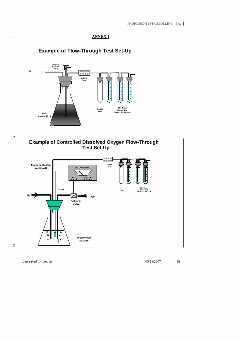
PROPOSED TEST GUIDELINE – 3xx
Last saved by huet_m 05/11/2007 51
ANNEX 1 1
Example of Flow-Through Test Set-Up
Air
TestMixture (1 L)
CO2 TrapsContaining
100 ml of 1.5 N KOH
SamplingPort with
Valve
VolatileTrap
Empty Trap
`2
3
Air N2
Solenoid Valve
DO Controller
Wastewater Mixture
CO2 Traps Containing
100 ml of 1.5 N KOH
Volatile Trap
Empty O2 Probe
Example of Controlled Dissolved Oxygen Flow-Through Test Set-Up
Trapping System (optional)
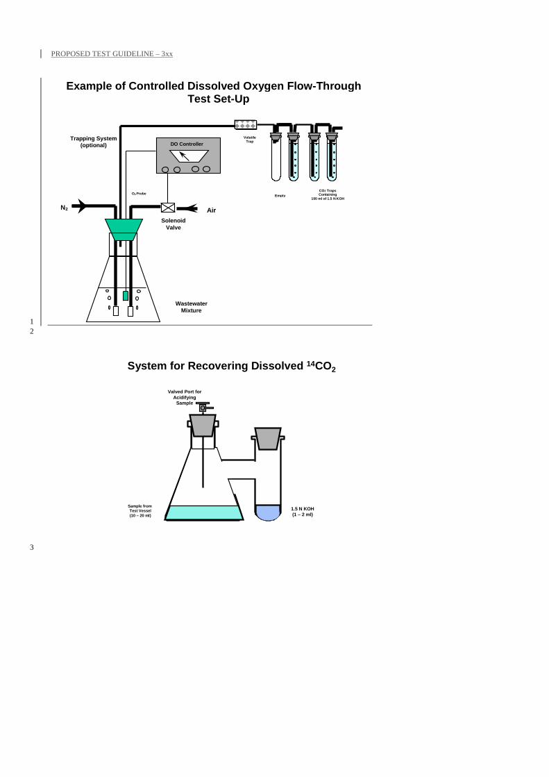
PROPOSED TEST GUIDELINE – 3xx
1 2
System for Recovering Dissolved 14CO2
1.5 N KOH(1 – 2 ml)
Valved Port for Acidifying
Sample
Sample from Test Vessel(10 – 20 ml)
3
Air N2
Solenoid Valve
DO Controller
Wastewater Mixture
CO2 Traps Containing
100 ml of 1.5 N KOH
Volatile Trap
Empty O2 Probe
Example of Controlled Dissolved Oxygen Flow-Through Test Set-Up
Trapping System (optional)
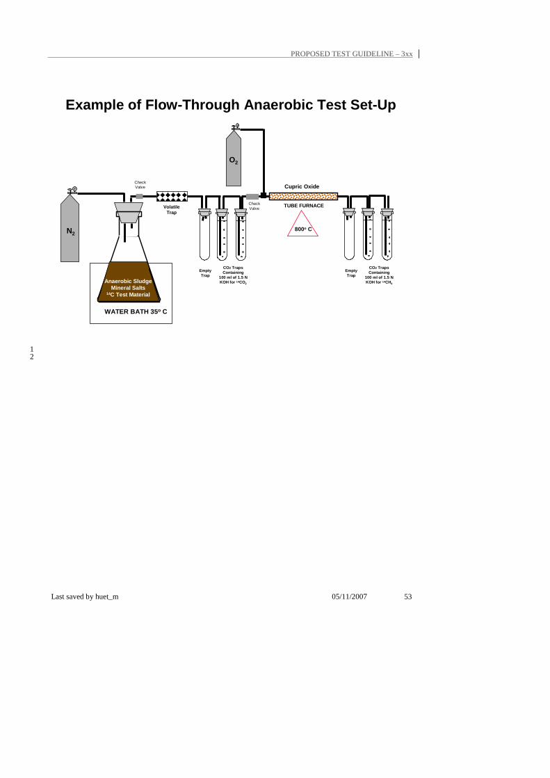
PROPOSED TEST GUIDELINE – 3xx
Last saved by huet_m 05/11/2007 53
N2
O2
Cupric Oxide
800o C
Anaerobic SludgeMineral Salts
14C Test Material
WATER BATH 35o C
TUBE FURNACE
CheckValve
CheckValve
CO2 TrapsContaining
100 ml of 1.5 N KOH for 14CH4
CO2 TrapsContaining
100 ml of 1.5 N KOH for 14CO2
Empty Trap
Empty Trap
Example of Flow-Through Anaerobic Test Set-Up
VolatileTrap
1 2