Embed Size (px)
Citation preview
ODOT
DESIGN BUILD
SCOPE OF SERVICES
PID: _87172__________ State Project Number: _847627 _
County:_Clinton Route: US 68___________ Section: 14.39___________
Table of Contents:
Section Page
1 Project Identification 2
1A Prima Facie Speed Limit 2 1B Railroad Coordination 2 1C Airway/Highway Clearance 2 2 Pre-bid Meeting 33 Addenda Process 3 4 Pre-qualification 35 Design Consultant 3 6 Scope of Work 47 Field Office 68 General Provisions for The Work 11 9 Hazardous Materials 11
10 Environmental 11 11 Right of Way (ROW) 13 12 Utilities 14 13 Design and Construction Requirements: Maintenance Of Traffic (MOT) 21 14 Design and Construction Requirements: Location & Design 22 15 Design and Construction Requirements: Structures 26 16 Design and Construction Requirements: Traffic Control 27 17 Project Schedule Requirements 30 18 Plan Submittals and Review Requirements 30 19 Buildable Units 35 20 21
Differing Site Conditions Index of Attachments
36 38
1. PROJECT IDENTIFICATION
PID: 87172 State Project Number: 487627 . County: Clinton Route: US 68 Section: 14.39 . Local Route Name: S. South St. . Highway Functional Classification: Urban Principal Arterial . Federal Aid System: Federal Aid Primary Route 18 . Structure Identification: Bridge Number: CLI-68-1443 Over: Lytle Creek . Structure File Number: 1401173 .
1.1 Design Designation:Location: On US 68 from 0.26 mi (Woodland Dr.) to 0.34 mi north of the southern intersection with SR 134. Current ADT (2013): 17,300 . Design Year ADT (2033): 23,800 . Design Hourly Volume: 2,142 . Directional Distribution: __0.55 . Trucks: 6.7% . Design Speed: 35 mph . Legal Speed: 35 mph . Design Functional Classification: Urban Principal Arterial . NHS Project: No X .
1.2 Existing plans: The following existing plans are available for review at the District Office. These plans will also be made available online by the Office of Contracts.
Archive Year Plan Name Plan Description 08C0743 1931 Bridge over Lytle Creek Original Construction 08C0718 1975 GRE-68-13.70 / 14.27 Deck Replacement 08R1069 1931 S.H. 175~”Wilmington” Original Bridge Right-of-Way
Please contact Scott Kramer [email protected] (513-933-6610) These are NOT as-built plans. The Design-Build Team (DBT) is advised to verify the preceding referenced plans to determine if they accurately depict existing field conditions.
1A PRIMA FACIE SPEED LIMIT (Not Applicable)
1B RAILROAD COORDINATION (Not Applicable)
1C AIRWAY/HIGHWAY CLEARANCE
THIS PROJECT HAS BEEN IDENTIFIED AS BEING WITHIN THE INFLUENCE AREA OF A PUBLIC USE AIRPORT OR HELIPORT. NO TEMPORARY STRUCTURES OR CONSTRUCTION EQUIPMENT AT MAXIMUM OPERATING HEIGHT SHALL EXCEED A HEIGHT OF 100 FT. IF ANY TEMPORARY STRUCTURES OR CONSTRUCTION EQUIPMENT WILL EXCEED THIS HEIGHT, FURTHER COORDINATION WITH THE FEDERAL AVIATION ADMINISTRATION (FAA), AND ODOT OFFICE OF AVIATION, WILL BE NECESSARY PRIOR TO ERECTING SUCH TEMPORARY STRUCTURES OR OPERATING SUCH EQUIPMENT ON THE PROJECT. THE CONTRACTOR WILL BE REQUIRED TO SUBMIT FORM 7460-1 TO THE FAA. A COPY OF THE SUBMISSION AND TWO COPIES OF FORM 7460-1 SHALL BE FORWARDED TO THE ODOT OFFICE OF AVIATION.
NO TEMPORARY STRUCTURES OR CONSTRUCTION EQUIPMENT SHALL EXCEED THE PERMISSIBLE HEIGHT, UNTIL A COPY OF THE FAA APPROVAL AND ODOT OFFICE OF AVIATION PERMIT HAS BEEN FURNISHED TO THE PROJECT ENGINEER.
Express Processing Center The Federal Aviation Administration Ohio Department of Transportation Southwest Regional Office Office of Aviation Air Traffic Airspace Branch ASW-520 2829 West Dublin-Granville Road 2601 Meachan Blvd. Columbus, Ohio 43235 Fort Worth, TX 76137-4298 614-387-2346
2 PRE-BID MEETING
This meeting is to discuss and clarify all issues that the project may have.
Location: ODOT District 8, 505 S. SR 741, Lebanon, OH 45036 .
Date: April 1st, 2nd, 3rd, & 4th ________________________________________.
Time: To be Determined ____________________________________________.
3 ADDENDA PROCESS
All questions prior to the letting date shall be directed to:
Web submittal form: http://www.dot.state.oh.us/Divisions/ContractAdmin/Contracts/Pages/PBQs.aspx
4 PRE-QUALIFICATION
It is required that the bidder be an ODOT pre-qualified Contractor who has engaged the services of an ODOT pre-qualified Consultant to perform all the design, Right-of-Way, and construction work required in these Conceptual Documents. If the Consultant and/or the Sub-Consultant(s) submitted do not meet all the required qualifications, the Office of Contracts may reject the bid.
5 CONTRACTOR’S CONSULTANT
The Contractor must name the Consultant and all Sub-Consultant(s) in the space(s) provided below. If the Contractor is going to submit an electronic bid, then the Consultant and all Sub-Consultant(s) must be listed on the following web-page: http://www.dot.state.oh.us/DIVISIONS/PRODMGT/CONSULTANT/Pages/default.aspx. The Contractor must list relevant prequalification categories for prime and sub-consultants to show that the prequalification requirements listed below are satisfied. All Consultant names and addresses must be the same as that on file with the Department. The following work types must be performed by members of the Consultant Team (combination of Consultant and Sub-Consultant(s)): __Right-of-Way plan Development, Roadway non-Complex, Bridge Design Level 2, Geotechnical Engineering and all R/W acquisition Services Prequalifications except Relocation and Relocation Review.
Consultant
Firm Name: _________________________________________________ Address: _________________________________________________
List work types the Consultant will perform: _______________________________________________________________________ _______________________________________________________________________ _______________________________________________________________________
Sub-Consultant
Firm Name: _________________________________________________ Address: _________________________________________________
List work types the Sub-Consultant will perform: _______________________________________________________________________ _______________________________________________________________________
Sub-Consultant
Firm Name: _________________________________________________ Address: _________________________________________________ List work types the Sub-Consultant will perform: _______________________________________________________________________ _______________________________________________________________________
Restrictions on Participation in Design-Build Contracts:
Any Consultant who provided services to the Department that have been directly utilized in this design-build proposal or Scope of Services document will NOT be eligible to participate in this design-build contract for this project, either as a prime consultant or as a sub-consultant. Ineligible consultants include:
_So-Deep, Inc. . _____________________________________ _____________________________________
6 SCOPE OF WORK
Project Limits: From 14.39 To 14.47 . Project Length: 0.08 . Work Length shall be determined by the DBT.
The Consultant shall provide for the engineering services, design, preparation of right-of-way, and detail construction plans for the construction of the proposed project.
The Contractor shall provide for the furnishing of materials, construction and completion in every detail of all the work described in the Conceptual Documents in order to fulfill the intent of the contract.
Project Description: Replace Bridge CLI-68-1443 and perform approach roadway and sidewalk work. Completion date: November 1, 2013 . Warranties: N/A .
Perform the following work on Bridge CLI-68-1443 over Lytle Creek (SFN 1401173)
1. Replace existing bridge CLI-68-1443 over Lytle Creek with a new single span bridge within the following limitations:
a. The existing abutments shall be left in place to avoid any in-stream, gabion wall, or existing sanitary sewer impacts, but the existing abutments shall not be used to support any final vertical loads.
b. The proposed superstructure shall NOT be a truss, an unpainted weathering steel beam/girder bridge, or non-composite boxbeam bridge. The proposed structure shall not be comprised of any Fracture Critical or non-redundant elements.
c. The substructure shall be supported on a deep foundation. Borings are provided. See Attachments. 2. Bridge width shall be wide enough to accommodate two 12’ lanes, two 1’ shoulders, two 6’ wide sidewalks
and two 1’ wide barriers per standard drawing BR-2-98. 3. Maximize the apartment driveway width at the southwest corner of the bridge. The existing width is
approximately 30’ wide. The minimum acceptable driveway width is 20 feet wide. A flared or radius
concrete wall extending outside the clear zone may be necessary instead of a standard guardrail transition to protect US 68 traffic from the drop off and still accommodate the driveway width.
4. Paint all exposed structural steel with IZEU per 514 specifications. Federal Color 15526. (where applicable).
5. Seal all concrete surfaces per the BDM with epoxy urethane sealer, Federal Color 17778. 6. Stay-in-place metal forms will be allowed. See Attachment “A” for Stay-In-Place Metal Form requirements
and limitations. 7. The structure is in a FEMA flood zone and will require a flood hazard study and coordination with the local
flood plain administrator. Plans shall include hydraulic stream cross-sections as necessary. The contractor cannot raise the elevation of the 100 year flow relative to the existing structure and the bridge opening cannot be smaller than the existing opening. The following flow rates shall be used in the contractor’s analysis:
Q25 = 2080 cfs, Design Year Q100 = 2700 cfs, Flood Year Q500 = 3550 cfs, Scour (Flow rates use FIS data May 3, 2010)
8. The roadway profile shall match the approximate existing profile. 9. Provide a minimum of 6’ wide sidewalks across the bridge with 5’ sidewalks off the bridge. The sidewalks
on the left shall extend from the first road south of the bridge (Woodland Dr.) to just north of the northern bridge approach slab. The sidewalks on the right shall extend from the first driveway south of the intersection of Woodland Dr. and US 68 to the first road north of the bridge (Creekside Dr.). A total of 3 ADA compliant ramps will be required. Provide two ADA compliant ramps at the intersection of US68 and Creekside Dr. These curb ramps will be facing northeast and northwest. At the Woodland Drive, one ADA ramp will be installed in the northwest quadrant on the Woodland Drive and US 68 intersection going to the southwest quadrant of the same said intersection. At the bridge, the sidewalk will transition at the end of the approach slab down to the roadway shoulder using a 12:1 slope. All tapers and transitions from the bridge sidewalk to shoulder will be made off the bridge and approach slab. The intent is to provide a smooth non-snagging transition that can be removed at a future date when additional sidewalk is provided by the city. The City of Wilmington uses 2.5’ tree lawns with 5’ wide sidewalks as their standard in this area. See Attachment “Pedestrian Path Drawing” for intended pedestrian facility locations.
10. Provide and acquire R/W as necessary (estimated 5 parcels). 11. Provide a BARS rating per Section 900 of the Bridge Design Manual.
7 FIELD OFFICE
Field office Type A , as required by Construction and Material Specification Item 619, shall be available and completely functional no later than 1 week prior to the start of construction work.
8 GENERAL PROVISIONS FOR THE WORK
8.1 Governing Regulations: All services, including but not limited to survey, design and construction work, performed by the DBT and all subcontractors (including sub-consultants), shall be in compliance with all applicable ODOT Manuals and Guidelines.
The fact that the bid items for this Design-Build project are general rather than specific shall not relieve the DBT of the requirement that all work performed and all materials furnished shall be in reasonable conformity with the specifications. The Contractor’s Consultant shall reference in the plans the appropriate Construction and Material Specifications Item Number for all work to be performed and all materials to be furnished.
The attention of the Bidder is directed to the provisions of section 100 of the Construction and Material Specifications as modified in the design-build proposal.
It will be the responsibility of the DBT to acquire and utilize the necessary ODOT manuals that apply to the design and construction work required to complete this project.
The current edition, including updates released on or before the prebid meeting date, of the following ODOT Manuals and Guidelines shall be met or exceeded in the performance of the design and construction work required to complete this project:
Bridge Design Manual Location and Design Manuals
Volume One - Roadway Design Volume Two - Drainage Design Volume Three - Plan Preparation
Pavement Design & Rehabilitation Manual Specifications for Geotechnical Explorations Survey Manual Construction and Material Specifications Proposal Notes for Construction and Material Specifications Supplemental Specifications for Construction and Material Specifications Item Master Manual for Abandoned Underground Mines - Inventory and Risk Assessment Pavement Design and Rehabilitation Manual State Highway Access Management Manual Standard Construction Drawings Plan Insert Sheets Traffic Engineering Manual Ohio Manual of Uniform Traffic Control Devices Real Estate Administration Policies and Procedures Manual:
Appraisal Acquisition Property Management Relocation ROW Plans Utilities Wireless Communication Tower Manual
Environmental Services Handbooks and Guidelines Waterway Permit Manual Design Mapping Specifications CADD Engineering Standards Manual Geotechnical Bulletins Project Development Process Manual (Appendix B)
8.2 Basis of Payment: All Items covered by Construction and Material Specifications, Supplemental Specifications, Proposal and Special Provision notes with unit price as a basis of payment will be paid for under the appropriate Lump Sum bid item, unless a unit line price item has been established in the Scope Of Services.
The Consultant shall be required to furnish the Department with a complete breakdown of the lump sum bid items. The breakdown shall include materials to be used in the work, and shall be in sufficient detail to provide ODOT with a means to check partial payment requests.
8.3 Final Payment: The DBT shall prepare and submit the following prior to the request for final payment:
1. All original project files and notes utilized in the preparation of the survey, design and construction of the project
2. Record-Drawings Plans as required in section 8.4 below.
8.4 Record-Drawing Plans:
A. General: At the completion of the work, prior to final acceptance of the construction, the Consultant shall furnish the Department Record-Drawing construction plans. When the Record-Drawing plans are completed the Consultant shall professionally endorse (sign and seal) the title sheet.
Record-Drawing plans shall be submitted using Tiff Images. Tiff Images shall be created according to the documentation on the Office of Contracts website (http://www.dot.state.oh.us/DIVISIONS/CONTRACTADMIN/CONTRACTS/Pages/TIFF.aspx)
In addition to the information shown on the construction plans, the Record-Drawing plans shall show the following:
1. All deviations from the original approved construction plans which result in a change of location, material, type or size of work.
2. Any utilities, pipes, wellheads, abandoned pavements, foundations or other major obstructions discovered and remaining in place which are not shown, or do not conform to locations or depths shown in the plans. Underground features shall be shown and labeled on the Record-Drawing plan in terms of station, offset and elevation.
3. The final option and specification number selected for those items which allow several material options under the specification (e.g., conduit).
4. Additional plan sheets may be needed if necessary to show work not included in the construction plans.
Notation shall also be made of locations and the extent of use of materials, other than soil, for embankment construction (rock, broken concrete without reinforcing steel, etc.).
The Plan index shall show the plan sheets which have changes appearing on them.
Two copies of the Record-Drawing plans shall be delivered to the Project Engineer for approval upon completion of the physical work but prior to the request for final payment. After the Department has approved the Record-Drawing plans, the original tracings and the associated electronic files shall be delivered to the District Planning and Engineering Administrator. Acceptance of these plans and delivery of the original tracings and the associated electronic files is required prior to the work being accepted and the final estimate approved.
The delivered original tracings shall be prepared in conformance with the Location and Design Manual, Volume 3, Section 1200 - Plan Preparation.
B. CADD files supplied by Consultant: X Yes NoIf marked yes, the Consultant shall comply with ODOT’s CADD Standards, and supply files in accordance with the CADD Engineering Standards Manual. All data shall be provided to the Department according to the provisions as detailed under the appropriate CADD links accessed from the Department’s Office of Production’s web site. This includes, but is not limited to, the level assignments, symbols, lines and line styles that are to be used, line weights, cells, placement of text and file naming conventions. The web site can be accessed at the following URL address:
http://www.dot.state.oh.us/Divisions/ProdMgt/Production/CADD/Pages/default.aspx http://www.dot.state.oh.us/Divisions/ProdMgt/Production/Pages/default.aspx
The following can be accessed from the above URL addresses:
1. ODOT CADD Standard files by selecting the “Microstation Downloads” link 2. ODOT’s Location and Design, Volume 3 by selecting the “L&D Manual Vol. 3" link 3. ODOT’s GEOPAK Standards by selecting the “GEOPAK Downloads” link
The Department will accept CADD files on CD ROM or DVD electronic media.
1. The Consultant shall submit all CADD information produced in the process of plan development. All CADD information shall be submitted in the current version of MicroStation (*.dgn) format as indicated in the CADD Engineering Standards Manual. This requirement ensures that ODOT receives an end product that is directly usable on ODOT’s CADD systems without additional work. The responsibility to provide the Department with correct and complete CADD data rests with the consultant.
2. The Consultant shall submit all GEOPAK information produced in the process of plan development according to L&D Volume 3, Section 1500. The submission shall include all files generated by GEOPAK as the result of the plan processing and these files shall include but are not limited to the following: a. Coordinate databases (*.gpk) b. Digital terrain models (*.tin) c. Original cross section (XS) cell design files d. Edited observation files (*.obs) e. ASCII text files containing all raw point data (PT #, X, Y, Z, Linking Code/Mapping
Code) f. ASCII text files containing all adjusted point data (PT #, X, Y, Z, Linking Code/Mapping
Code, Attribute data if any) g. ASCII text file(s) listing chain data for all existing and proposed horizontal alignments;
including the centerline of construction, the centerline of right of way and ramp baselines.
h. ASCII text file(s) listing vertical alignment data for all existing and proposed profiles.i. ASCII text files listing the Northing, easting, station, offset and elevation for all existing
and proposed monuments.
A separate file name should be used for each horizontal or vertical alignment. The CADD Engineering Standards Manual provides specific requirements for the content of the required ASCII reports and provides directions on how to create these reports using GEOPAK software.
These requirements and procedures may be updated from time to time with notification in the Design Reference Resource Center (DRRC) website which is located at the following URL, http://www.dot.state.oh.us/drrc/. Organizations exchanging ODOT CADD data are responsible for ensuring they are using the current version of these requirements, CADD reference manuals, ODOT cell files and ODOT seed files.
8.5 Post-Letting Conference: Within 7 days after bid opening, the apparent low bidder DBT shall contact the Office of Estimating of the Division of Construction Management to discuss the Lump Sum estimate with the Department.
8.6 Partnering Agreement: The Contractor is invited to enter into a(n) informal__ cooperative partnership agreement with the Department on this project. The objective of this agreement is the timely completion of the work and a quality product that will be a source of pride to both the Department and the Contractor. This Partnering Agreement will not affect the terms and conditions of the contract. It is a document which is solely intended to establish an environment of cooperation between the parties. The cost of the partnering workshop(s) will be agreed to and shared equally between the Department and the Contractor. The Contractor will pay all costs directly and the Department will authorize its share to the Contractor by change order. The Contractor is not entitled to any mark ups on the invoiced cost.
8.7 Communication: All communication during design and construction shall be with the District Project Manager and the District Project Engineer.
District’s Project Manager’s Name: Scott Kramer Phone number: 513-933-6610 Fax: 513-933-8252
E-mail: [email protected] .
The District Project Engineer shall be named at the pre-design meeting.
At the pre-design meeting, the Contractor shall name a Project Manager who will act as a liaison between the DBT and the Department.
The Contractor will advise the Project Engineer a minimum of fourteen (14) days prior to the following: the start of construction activities, lane closures, and or road closures. The Project Engineer will forward this information to the District Public Information Officer (PIO) by FAX at (513) 932-7651 or email at [email protected]. The PIO will, in turn, notify the public, the local emergency services, affected schools and businesses, and any other impacted local public agency of any of the above-mentioned items, via media sources.
8.8 Permits: Contractor will be required to obtain a permit from the State or local government having jurisdiction, to perform any non-construction work within the existing Right of Way and/or limited access.
8.9 Entry On Private Property: The DBT, acting as The Department’s agent, may enter upon any lands within the State for the purpose of inspecting, surveying, leveling, digging, drilling, or doing any work deemed necessary in the execution of any survey authorized by the Director of Transportation in accordance with Section 5517.01 of the Ohio Revised Code and Section 102.6 (inclusive of Sections 102.61 through 102.66) of ODOT’s Survey Manual. Prior to performing said survey, the DBT will send notification letters indicating the date and duration of entry to the affected property owners no less than forty-eight hours nor more than 30 days prior to the date of entry for said survey in accordance with 102.6 of ODOT’s Survey Manual. The DBT shall forward copies of all notification letters distributed to ODOT’s Project Manager. Any subsequent claims for compensation due to damages incurred while said survey was being performed will be negotiated between the DBT and the affected property owners with final approval from ODOT’s Project Manager. Crop and property damage minimization and reimbursement information, together with the crop damage reimbursement formula and Special Waiver of Damage form, will be provided to the DBT by ODOT’s Project Manager. Any subsequent entries onto private property for the purpose of obtaining additional survey or soil information prior to the submission of the bid will be made in accordance with the procedures outlined in this section.
9 HAZARDOUS MATERIALS
The District has reviewed the site for the presence of asbestos or other hazardous materials. No hazardous materials were found.
10 ENVIRONMENTAL
10.1 Waterway Permits:
It is required that the bidder be aware of Section 404/401 Permits/Certifications for all projects impacting "waters of the US". The level of permit, that is Nationwide versus Individual 404 and 401, is determined by the exact amount of impact to "waters of the US", (i.e., acreage of fill activities in a stream or wetland or linear feet of work in a stream) and in some cases the waters impacted. All individual 404 Permits require 401 Water Quality Certification. Nationwide Permits are activity specific permits used to authorize projects with minor impacts. Projects with more than minor impacts require individual review by the U.S. Army Corps of Engineers and the Ohio Environmental Protection Agency.
The DBT should be aware of the Nationwide Permits and conditions as issued for the State of Ohio and should design projects to meet the requirements of these general permits to avoid the requirements for Individual 404/401 Permits if possible. The Nationwide Permits for the State of Ohio can be found at the various Corps of Engineers' web sites. The Huntington District's web site can be found at: http://www.lrh.usace.army.mil/.
Coordination of the waterway permits can take up to six (6) months for Individual 404 Permits. Therefore it is imperative that the DBT submit plans (i.e., plan & profile, cross-section and detail sheets for any bridges, culverts, or fill areas in waters) to the District Project Manager and the Office of Environmental Services, for permit determination, no less than 90 days prior to any in stream or wetland work. The review of plans, any required coordination or the processing of permit applications must be accomplished by the Office of Environmental Services prior to the commencement of construction activities. The DBT shall be responsible for completing applications for 404 Permits and 401 Water Quality Certification, if they are required. At no time will the DBT coordinate waterway permit issues directly with the permitting agencies unless directed to do so by the Office of Environmental Services.
All Waterway Permit requirements are found in the Waterway Permits Manual.
10.2 National Pollutant Discharge Elimination System (NPDES) permit:
The DBT shall submit to the ODOT Project Manager the total number of acres of earth disturbance activities for both off project and on project work in a timely manner. This information will be used to develop the NOI if required. The NOI will be submitted to the OEPA within 10 days after this information is received from the DBT. Approval from the OEPA takes 21 days and the ODOT Project Manager has 10 days to file the NOI so these 31 days will be counted for in the project schedule.
All temporary erosion control is the responsibility of the Contractor even if a SWPPP is not required. Earth disturbing activity is not permitted prior to the OEPA permit approval. For projects that require an NOI, the SWPPP must be in place prior to the initiation of any earth disturbing activity. All temporary erosion control work and the SWPPP if required will be per SS832. For information about OEPA's NPDES permit requirements see http://www.epa.state.oh.us/dsw/storm/index.html. Items used to implement the DBT's Erosion Control requirements are paid from an encumbered amount included in the proposal as a non-bid reference number. The proposal specifies the unit prices for the erosion control items. Payments for erosion control items that exceed the encumbered amount will be made by an Extra Work Change Order using the specified unit prices. The specified unit prices are fixed for the contract and may not be negotiated or adjusted for inflation or claimed changed condition.
10.3 Removal of Temporary Erosion Control Items
All temporary erosion control items shall be removed before the project is accepted. Removed materials shall become the property of the Contractor and shall be disposed of in accordance with the appropriate C&MS specifications.
10.4 Stream Crossing Investigations (flood plain analysis)
The Consultant shall perform a detailed flood plain analysis for each waterway crossing. The analysis shall be as per the Location & Design Manual and The Bridge Design Manual and as follows : The extent of the analysis shall be from a minimum of 560' downstream, to the greater of either 600’ upstream, or to the limits of the area inundated by the 100-year event. The results of the detailed flood plain study, supporting hydraulic calculations including HEC-RAS files, and recommendations shall be submitted to the District for review and comment prior to construction of the drainage structure. If the proposed crossing is located in a special flood hazard area as defined by FEMA, the detailed flood plain analysis shall be submitted concurrently to the local flood plain coordinator.
The Design Storm discharges to be used are provided in Section 6 (Scope of Work) provided in this document. Field survey is also provided by the District. The consultant is responsible for the hydraulic analysis and any field survey that is not provided.
11 RIGHT OF WAY (ROW), DBT REQUESTED ADDITIONAL RIGHT-OF-WAY
Once the DBT determines the additional permanent and/or temporary right-of way that is required for construction and/or utility relocation, the DBT, acting as an agent on behalf of ODOT, shall provide
acquisition services for the additional right-of way. Individuals engaged in right-of-way acquisition shall be selected from ODOT’s pre-approved list. Right-of-way acquisition services shall include project management, title research, appraisal, negotiation, closings, relocation assistance services and property management. The DBT shall provide right-of-way plans and pre-approved legal descriptions as well as associated survey work, including staking of right-of way. Appraisal review must be conducted by an independent third party. The DBT must coordinate all appraisal assignments with ODOT before authorizing an appraiser to prepare an appraisal report. ODOT will file the appropriation for any parcel where a condemnation action is necessary. ODOT will retain authority for approving just compensation, relocation benefits and administrative/case settlements. ODOT must issue a “Notice to Commence” right-of way acquisition to the DBT prior to any work beginning. ODOT must also issue a Notice to Commence Construction to the DBT once the property has been acquired prior to commencing construction on the property. The DBT will not be responsible for the actual cost of purchase of right-of-way, including utility easements, as part of the Project. The DBT shall carry out the responsibilities as outlined on the Office of Real Estate Scope Definitions for Right-of Way Services. See Attachment.
During the acquisition process, and for a period of five years after final payment is made to the DBT for any phase of the work, or until the State has indefeasible title to the property, all Project documents and records not previously delivered to ODOT, including but not limited to design and engineering costs, construction costs, costs of acquisition of rights-of way, and all documents and records necessary to determine compliance with the laws relating to the acquisition of rights-of-way and the costs of relocation of utilities, shall be maintained and made available to ODOT for inspection or audit. Throughout the design, acquisition, and construction phases of the Project, copies of all documents/correspondence shall be submitted to ODOT.
Existing right of way lines will be located by the DBT based on requirements specified in Chapter 4733-37 of the Ohio Revised Administrative Code (Board Rules) governed by regulations outlined in Chapter 4733, Ohio Revised Code (Regulation Laws). It is the responsibility of the DBT to research existing right of way information from all available sources including but not limited to ODOT records, County road records, Commissioners’ Journals and records of other County offices to the extent necessary to provide an accurate basis for the establishment of the existing right of way.
The DBT will stake and flag the existing right of way and any newly purchased right of way in the field prior to the start of construction and will maintain said stakes and flags throughout the duration of the project.
The Consultant will identify and show all right of way encroachments on the construction plans at the Conceptual Review Submission. ODOT’s Project Manager will be responsible for clearing all encroachments on Federal-aid projects in accordance with standard encroachment removal.
The Design-Build team shall include the cost of the right-of-way plan preparation and pre-approved legal descriptions as well as associated project management and survey work, including staking of right-of way in the Lump Sum Cost for Design of Right-of-Way Plans and Lump Sum Cost for Right-of-Way Services. The Design-Build Team shall include the cost of title research, appraisal, negotiation, closings, relocation assistance services, property management, as well as associated survey and project management work with the Lump Sum cost for Right-of-Way Acquisition Services. The DBT is referred to Attachment E for additional requirements.
12 UTILITIES
12.1 GENERAL
The Department believes that the work limits provided in the Appendix includes sufficient room for utility relocations. The DBT shall be responsible for coordination with the owners of all public and private/investor utility facilities affected by the project. The resolution of any conflicts between utility facilities and the construction of the project shall be the responsibility of the DBT.
A. Any required relocation of public utility facilities shall be included in the DBT’s bid (cost) and schedule.
B. The DBT is responsible for all coordination and schedule risk for relocation of private/investor owned utility facilities, except as described in Section 12.4.2 - Deadlines and Delays.
C. ODOT will make all determinations of compensable rights related to utility facility design, relocation, modification and construction. Except as specifically indicated in the contract documents, no additional compensation or time will be granted for any delays, inconveniences, or damages sustained by the DBT due to interference from utility facilities or utility facility relocations.
D. The department has reviewed the utilities in the project area and determined the following design and relocation of the following utilities are compensable:
1. _City of Wilmington__________ 2. ___________________________
12.2 Governing Regulations for Utility Design and Construction.
Any utility relocation work performed by the DBT shall be consistent with ODOT’s utility relocation process. This work shall also be consistent with the utility owner’s reasonable, written specifications, standards of practice and construction methods, as well as any applicable ODOT, and City of Wilmington permit requirements.
The plans for the design of the utility work shall show at the minimum the following information: existing topography, right-of-way, lanes of travel and the location of the utilities. When the DBT develops utility relocation plans, these plans shall be subject to review by ODOT, the City of Wilmington, and the involved utility, as applicable.
Utilities Special Provisions in addition to the Governing Regulations listed in section 8.1 of this document and section 153.64 of the Ohio Revised Code must be followed.
12.3 Existing Utilities: The District Utility Coordinator, in concurrence with the registered Underground Utility Protection Services- Ohio Underground Protection Service (OUPS) and Oil and Gas Producers Underground Protection Service (OGPUPS) and other utility owners that are non-members of any utility protection services, has determined that the following utilities are located in the area of the project:
Dayton Power & Light Company 1900 Dryden Road Dayton, Ohio 45439 937-331-4132 (John Kenton)
Vectren Energy (Underground Gas) 6500 Clyo Road Centerville, Ohio 45459 937-312-2533 (Don Specht)
Frontier Communications 241 S. Nelson Avenue Wilmington, Ohio 45177 937-382-4224 (Scott Pfister)
Time Warner Cable 11252 Cornell Park Drive
Cincinnati, Ohio 45242 513-469-5483 (Gary Napier)
City of Wilmington (Sanitary & Water) 69 N. South Street Wilmington, Ohio 45177 937-382-6509 (Larry Reinsmith)
12.4 Utility Coordination Responsibilities: Utility relocations shall be identified by the DBT. The DBT shall design the project to minimize the scope and extent of additional relocations, where possible. When relocations are necessary, coordination of these relocations with the involved utility shall be the responsibility of the DBT.
Only those utility facilities directly affected by the proposed construction shall be relocated or adjusted. If the DBT desires the temporary or permanent adjustment of the utilities for their benefit, they shall conduct all negotiations with the utility owners and pay all costs associated with the adjustment. The DBT shall assume all schedule impacts from these relocations or adjustments.
The DBT shall:
A. Identify and contact the owners of all utilities within the project area to verify the nature, extent and location of their existing facilities
B. Identify all impacted utility facilities
C. Provide all project construction plans, SUE and geotechnical information to these utilities
D. Coordinate all work with the affected utility owners
E. Schedule and conduct coordination meetings during design and construction
As soon as it is feasible after the final plan is approved by the Department, the DBT shall stake the existing ROW (and new ROW if additional is acquired) in the field and shall perform clearing and grubbing within that ROW as required by the specifications and the proposal documents, in order to allow utility relocation and reduce potential delays. ROW stakes shall be maintained and updated as needed throughout the project length.
The DBT shall be cognizant of the project's impact on utility facilities. In the event utility rearrangements are required, the project shall not be designed to preclude legal occupancy of the highway ROW by the rearranged utility facilities. The DBT needs to give any existing utility room to relocate within the project even if new right-of –way needs to be purchased.
The DBT shall coordinate all existing utilities with construction activities on this project. The DBT shall insure that potential delays in coordination and relocation of the affected utilities are minimized. The DBT shall copy the ODOT Project Manager and the District Utility Coordinator on all correspondence or phone calls between the DBT and each utility. This shall include the submittal of plans to each utility.
A meeting at or near the preliminary review shall be held between the DBT, the District Utility Coordinator and the utility owners to determine if any significant utility relocations can be eliminated or mitigated.
Any ineligible, unnecessary, or betterment to the utility's facility will be the responsibility of the utility and not the project. Determination of eligibility can be coordinated through the District Utility Coordinator. Payment for betterments or ineligible costs shall be made by the appropriated utility through ODOT to the Contractor.
The DBT is responsible for establishing a schedule of utility coordination meetings commensurate with the complexity of each utility’s relocation issues. The DBT shall notify the ODOT District Utility Coordinator at least three (3) Business Days in advance of each of the meetings. The ODOT District Utility Coordinator will participate as necessary. The DBT is responsible for keeping meeting minutes and providing this documentation to ODOT within two (2) Business Days following each meeting.
The DBT shall copy the ODOT’s District Utility Coordinator and Engineer on all correspondence related to utility facilities.
The cost of all utility coordination shall be bid as a Lump Sum Item – Special Utility Coordination.
12.4.1 SCHEDULING OF UTILITY RELOCATION WORK
The Design-Build team shall submit a Critical Path Method (CPM) schedule in accordance with Proposal Note 107. The DBT shall confirm the relocation construction timeframes required by utility owner and incorporate these timeframes into the project’s CPM schedule.
The DBT shall consider special scheduling requirements of utilities, such as peak load periods (e.g., winter gas loads and summer electric loads) when developing their CPM schedule.
The DBT shall pay all costs incurred by the public and private utility owner associated with the use of DBT proposed construction acceleration methods, (e.g., the use of overtime or subcontractors). These acceleration costs are NOT eligible for reimbursement by the Department.
When the DBT prepares a utility facility relocation plan, the utility owner will review and approve/reject the design prepared by the DBT no later than 28 calendar days after its submission to the utility owner, unless a different time period is agreed to by both parties. If a utility owner rejects any design work, the DBT shall immediately notify ODOT, in writing, of the grounds for rejection and suggestions for correcting the problem. The DBT shall correct the design and resubmit to the utility owner for review. This compliance review is anticipated to take 14 calendar days.
When the utility owner prepares a utility facility relocation plan, ODOT, and the DBT shall review the design and/or permit application to ensure that the relocation does not interfere with other proposed construction activities, including relocations of other utility facilities. This review shall be completed no later than 14 calendar days after its submission to the DBT, unless a different time period is expressly agreed to by both parties. The DBT shall compile and provide written review comments to ODOT and the utility owner.
The DBT shall be responsible for inspection of private/investor owned utility relocation to ensure that the relocation does not interfere with other proposed construction activities, including relocations of other utility facilities.
12.4.2 DEADLINES and DELAYS
The DBT shall be responsible for monitoring utility facility relocations including plan development, plan review, and construction. The DBT shall promptly notify ODOT if a utility facility owner is not complying with the agreed upon time frames indicated in Section 12.4.1. If the DBT provides documentation confirming that a utility has failed to relocate their facilities in a timely manner, an Obstruction Removal Notice will be issued by ODOT or the City of Wilmington, as appropriate. However, be advised that the use and responsibilities of an Obstruction Removal Notice only govern the relocation process, when the utility in question is located within the current right-of-way. If the utility is located in their own easement, the notice does not apply and relocation delay responsibility is based on the relocation schedule provided by the utility. ODOT will not be responsible for payment of delay claims associated with utility coordination/relocation, unless the DBT is able to provide ODOT with sufficient documentation for an Obstruction Removal Notice.
12.4.3 CHANGES TO THE UTILITY WORK
Once a utility relocation has begun, the DBT shall not make any changes to the proposed project design which would necessitate a second relocation of the utility facility. However, the DBT may make changes if they agree to absorb the schedule impact and provide full compensation for 100 percent of all costs (design and construction) associated with the second relocation to the utility company. If this is the case, the DBT shall provide ODOT with documentation of their agreement with the involved utility.
12.4.4 UTILITY OWNER TO PERFORM INSPECTIONS
The utility owner may perform inspections of construction of any utility work that is performed by the DBT on their facility. The DBT shall notify ODOT of any such inspections. The DBT shall provide ODOT with written documentation of all utility comments and their resolution. The DBT shall provide safe access and any necessary traffic control for any utility work inspections performed by the utility owner.
12.4.5 REIMBURSEMENT PROCESS
If a utility company notifies the DBT that they believe any utility relocation work is reimbursable (to the utility) or requires additional right of way acquisition by ODOT, the DBT shall immediately notify ODOT.
12.4.6 CONTINUITY OF UTILITY SERVICE
The DBT shall ensure that all utilities remain operational during all phases of project construction to the greatest extent practicable. Necessary interruptions of service, including proposals for shutdowns and temporary diversions of affected utilities, shall be approved by the involved utility.
The DBT shall conduct regular communication with residents and businesses affected by utility interruptions. The DBT shall contact and provide written notification to all affected residents and businesses 48 hours in advance of a utility interruption, and shall maintain a record of each notification. Notices shall indicate the purpose and expected duration of the interruption, and provide information indicating how those affected by the interruption can contact the DBT. Notices shall meet ODOT's communications style and be pre-approved by ODOT before dissemination. Such notices may also be provided by ODOT. This applies only to utility interruptions that are a result of DBT work activities. It does not apply to interruptions conducted by and coordinated by the utility owners.
In the event of an emergency involving a utility interruption, the DBT shall notify the utility owner in accordance with utility company standards and local emergency services.
Where the DBT is responsible for the performance of utility relocation work, in order to maintain the service continuity of the utility owner’s facilities to the extent practicable during that performance of work, the DBT, at its cost, shall:
A. Keep the utility owner fully informed of schedules, including coordinating with the utility owner with regard to their design, construction and inspection of utility work performed by the DBT
B. Keep the utility owner fully informed of changes that affect their facilities
C. Keep the utility owner involved in making the decisions that affect their facilities so the utility owner is able to provide uninterrupted service to its customers, or be subject to the least interruption practicable
All the utility owner’s facilities shall remain fully operational during all phases of project construction, except as specifically allowed and approved by the utility owner.
12.5 EXISTING UTILITY LOCATIONS
Existing utility facilities to be abandoned must be disconnected and removed or abandoned to ground (abandoned in place). Wooden Poles shall be removed in their entirety.
12.5.1 UNDERGROUND UTILITIES
Existing public and private/investor owned underground utility facilities within the project area are tentatively located and identified in the attachments. Locations, sizes and depths (when indicated) have been compiled by a combination of efforts including reviewing existing facility plans, field survey and subsurface utility engineering (SUE) efforts. However, the DBT is advised that the locations, sizes and depths should be considered tentative. The DBT is responsible for final verification of all subsurface utility facility locations, both public and private/investor owned, within the confines of their work. Record documents used in the SUE effort are included for reference in the Attachment.
12.5.2 OVERHEAD UTILITIES
Existing private/investor owned overhead utility poles within the project area are tentatively located and identified in the appendices. Locations have been compiled by a combination of efforts including reviewing existing facility plans and field survey. However, the DBT is advised that the locations should be considered tentative. The DBT is responsible for final verification that all overhead utility facility locations including type, number and elevation of lines, and related above ground facilities, private/investor owned, within the confines of their work and project limits, meet ODOT right of way permit standards. Record documents used in the SUE effort are included for reference in the Attachment.
12.6 UTILITY CONFLICTS
Utility conflicts shall be identified by the DBT as a result of chosen substructure unit locations; retaining wall construction; roadway and pavement construction; excavation and embankment limits; DBT selected construction means and methods; and other construction. Underground utilities shall not be allowed to be located under the bridge’s proposed abutments or wingwalls.
12.7 PROTECTION OF UTILITY FACILITIES
The DBT shall coordinate project construction with utility adjustments and take all necessary precautions to prevent disturbance to utility facilities.
The DBT shall perform work in a manner that will cause the least reasonable inconvenience to the utility owner and those being served by the utility owner. Existing, adjusted, or new utility facilities that are to remain within the right-of-way of the project shall be properly protected by the DBT to prevent disturbance or damage resulting from project construction operations. If the DBT encounters a previously unknown utility that requires adjustment, they shall not interfere with the utility but shall take the proper precautions to protect the facility or take appropriate actions, per the contract documents, to coordinate the adjustment of the facilities.
12.8 KNOWN UTILITY FACILITY RELOCATIONS
The utility pole at station 760+37 ± Left owned by Frontier Communication will need to be moved out of the driveway to mitigate the reduced driveway width that will result from this project. This pole also has electric by Dayton Power and Light Company, and cable by Time Warner Cable. This relocation shall be performed by the respective utilities and coordinated by the DBT. See the Utility note in the Proposal for additional information.
12.8.1 Other Utility Facility Relocations
Additional utility facility relocations, modifications and adjustments may be necessary as a result of the details of the DBT’s final design. All such utility facility relocations, modifications and adjustments shall be coordinated by the DBT with the affected utility. All such utility facility relocations, modifications and adjustments shall be executed by the DBT or the affected utility owner as appropriate.
13 DESIGN AND CONSTRUCTION REQUIREMENTS : MAINTENANCE OF TRAFFIC (MOT)
Maintenance of Traffic (MOT) Special Provisions in addition to the Governing Regulations listed in section 8.1 of this document:
13.1 General: All temporary MOT devices shall comply with the National Cooperative Highway Research Program (NCHRP) 350 Hardware report.
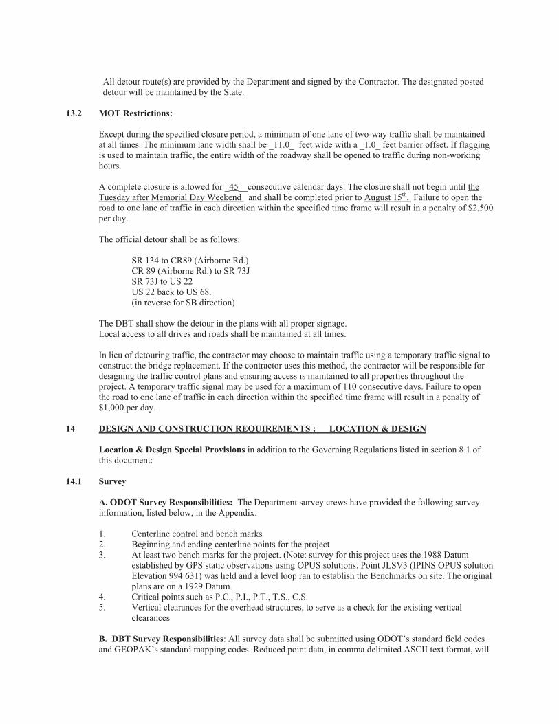
All detour route(s) are provided by the Department and signed by the Contractor. The designated posted detour will be maintained by the State.
13.2 MOT Restrictions:
Except during the specified closure period, a minimum of one lane of two-way traffic shall be maintained at all times. The minimum lane width shall be _11.0_ feet wide with a _1.0_ feet barrier offset. If flagging is used to maintain traffic, the entire width of the roadway shall be opened to traffic during non-working hours.
A complete closure is allowed for _45__consecutive calendar days. The closure shall not begin until the Tuesday after Memorial Day Weekend and shall be completed prior to August 15th. Failure to open the road to one lane of traffic in each direction within the specified time frame will result in a penalty of $2,500 per day.
The official detour shall be as follows:
SR 134 to CR89 (Airborne Rd.) CR 89 (Airborne Rd.) to SR 73J SR 73J to US 22 US 22 back to US 68. (in reverse for SB direction)
The DBT shall show the detour in the plans with all proper signage. Local access to all drives and roads shall be maintained at all times.
In lieu of detouring traffic, the contractor may choose to maintain traffic using a temporary traffic signal to construct the bridge replacement. If the contractor uses this method, the contractor will be responsible for designing the traffic control plans and ensuring access is maintained to all properties throughout the project. A temporary traffic signal may be used for a maximum of 110 consecutive days. Failure to open the road to one lane of traffic in each direction within the specified time frame will result in a penalty of $1,000 per day.
14 DESIGN AND CONSTRUCTION REQUIREMENTS : LOCATION & DESIGN
Location & Design Special Provisions in addition to the Governing Regulations listed in section 8.1 of this document:
14.1 Survey
A. ODOT Survey Responsibilities: The Department survey crews have provided the following survey information, listed below, in the Appendix:
1. Centerline control and bench marks 2. Beginning and ending centerline points for the project
3. At least two bench marks for the project. (Note: survey for this project uses the 1988 Datum established by GPS static observations using OPUS solutions. Point JLSV3 (IPINS OPUS solution Elevation 994.631) was held and a level loop ran to establish the Benchmarks on site. The original plans are on a 1929 Datum.
4. Critical points such as P.C., P.I., P.T., T.S., C.S. 5. Vertical clearances for the overhead structures, to serve as a check for the existing vertical
clearances
B. DBT Survey Responsibilities: All survey data shall be submitted using ODOT’s standard field codes and GEOPAK’s standard mapping codes. Reduced point data, in comma delimited ASCII text format, will
be provided for all surveyed points. This data will include: point number, x coordinate, y coordinate, elevation and point ID. Customized GEOPAK information is available on the ODOT CADD web site.
Monumentation shall not be disturbed. If the DBT does disturb the monumentation, then it shall be replaced, in-kind, by a Registered Surveyor, with a current registration, recognized by the Ohio State Board of Registration for Professional Engineers and Surveyors. Costs associated for this item shall be borne by the DBT. Copies of all monumentation changes shall be forwarded to the District Real Estate Administrator.
All control points, provided by ODOT, shall be included in the ASCII file supplied by the DBT to ODOT. They should retain the original point numbers and coordinate values as assigned by ODOT.
The DBT shall provide the following items prior to final acceptance of the Record-Drawing plans:
1. Copies of all field notes (written or electronic) shall include the following information: a. Date b. Crew members c. Weather conditions, including temperature, barometric pressure, etc. d. Instrument(s) used (Serial Number) e. Raw observation field data f. Other notes as needed
2. Copies of all Deeds, Plats, Maps and other written evidence used to establish points related to the project including summaries of all parole evidence acquired as a part of the survey operation.
3. Listing of all found monumentation (Horizontal and Vertical).
4. Listing of all monumentation set as part of the project (Horizontal and Vertical) including reference ties for recovery.
5. All monumentation shall be located utilizing NAD 83 (Horizontal Data), NAVD 88 (Vertical Data).
6. Short report indicating adjustment factors and methods, signed and certified by a Registered Surveyor (State of Ohio). The Registered Surveyor (State of Ohio) shall include in the report the datum used and all associated adjustments used.
14.2 Vertical and Horizontal Alignment:
A. Maintain / Match the existing vertical and Horizontal Profile. B. Provide cross-sections at a minimum of 25’ intervals.
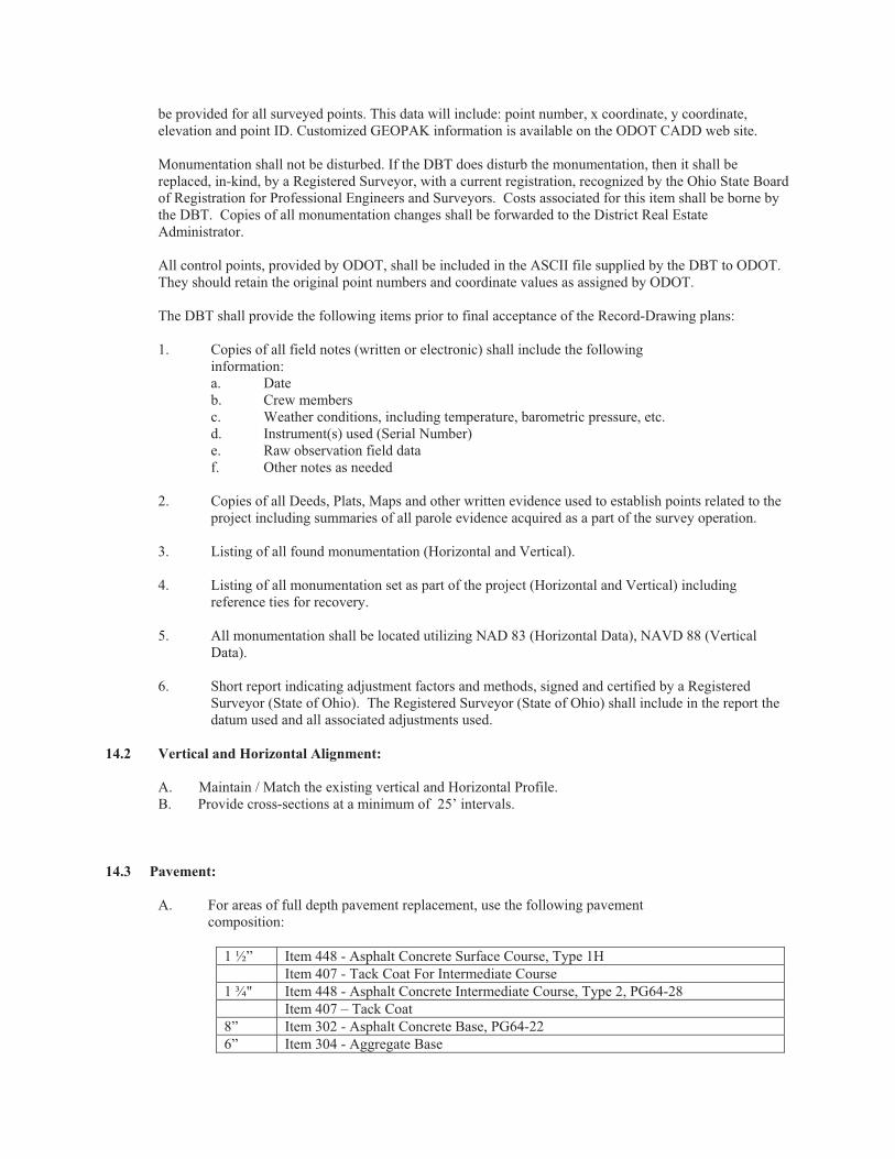
14.3 Pavement:
A. For areas of full depth pavement replacement, use the following pavement composition:
1 ½” Item 448 - Asphalt Concrete Surface Course, Type 1H
Item 407 - Tack Coat For Intermediate Course
1 ¾" Item 448 - Asphalt Concrete Intermediate Course, Type 2, PG64-28
Item 407 – Tack Coat
8” Item 302 - Asphalt Concrete Base, PG64-22
6” Item 304 - Aggregate Base
Item 204 - Subgrade Compaction
Item 605 – Underdrains
B. For areas within the project limits not being replaced by full depth pavement, remove and replace 1.5” of the above specified surface course
14.4 Roadway:
Lane Width: 12 feet . Curbed Shoulder Width: 1 foot . Sidewalk Buffer: 2.5 feet . Sidewalk Width: 5 feet .
Guardrail _Replace existing guardrail and end treatments within project limits to current standards.
Approach slabs: Min 20’ length. Approach slabs width shall match the full width of the bridge. Approach slabs shall be poured separately from the deck._
14.5 Drainage: Yes X ; No .
Replace existing drainage within project limits with a new closed drainage system. On the approach slabs, a type 2A curb shall be used. Beyond the limits of the approach slabs, new Type 6 curb shall be installed for the remaining length of the project.
Catch Basins grates shall not extend beyond the proposed 1 foot shoulder width. Alternate catch basins meeting other State DOT Standard catch basins may be used provided they are bicycle safe and meet the general intent of a standard ODOT catch basin.
14.6 Design Exceptions:
Previously approved Design Exceptions: None
The Consultant shall advise of any future design features that does not meet the minimum design criteria. The Consultant shall prepare all future design exceptions and submit to ODOT for approval.
14.7 Interchange Modification/Justifications Studies; N/A
14.8 Landscape: Yes ; No X .
14.9 Fencing: Yes _____; No _X__
14.10 Additional Description of Required Work and Special Provisions: N/A
15 DESIGN AND CONSTRUCTION REQUIREMENTS : STRUCTURES
15.1 Hydraulic data provided by ODOT: The Department has provided the following items listed below: 1. The flow rates that are to be used for the project are specified in Section 6. 2. Soil boring information in structure areas is provided in an attachment. 3. Approximate work limits used to determine environmental footprint, approximate R/W limits, and
preliminary utility coordination are provided in an attachment. These work limits are approximate. The Design-Build Team is responsible for determining the final work limits, acquiring the necessary R/W, and coordinating utility relocations as described in this document.
15.2 Existing Structures Identification:
Structure File No. 1401173
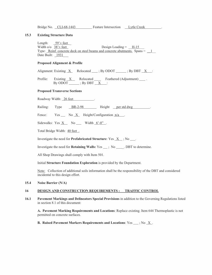
Bridge No. CLI-68-1443 Feature Intersection Lytle Creek .
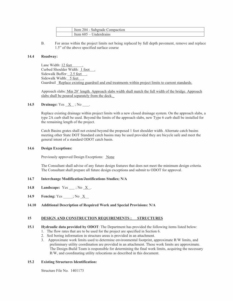
15.3 Existing Structure Data
Length: 59’± feet _ Width o/o 38’± feet Design Loading = __H-15___ Type: Reinf. concrete deck on steel beams and concrete abutments. Spans = __1__ Date Built: _1931___
Proposed Alignment & Profile
Alignment: Existing X Relocated ; By ODOT ; By DBT X :
Profile: Existing X Relocated Feathered (Adjustment) . By ODOT ; By DBT X :
Proposed Transverse Sections
Roadway Width: 26 feet .
Railing: Type BR-2-98 Height per std dwg .
Fence: Yes No X Height/Configuration n/a .
Sidewalks: Yes X No Width 6’-0” .
Total Bridge Width: 40 feet .
Investigate the need for Prefabricated Structure: Yes X ; No .
Investigate the need for Retaining Walls: Yes ; No _. DBT to determine.
All Shop Drawings shall comply with Item 501.
Initial Structure Foundation Exploration is provided by the Department.
Note: Collection of additional soils information shall be the responsibility of the DBT and considered incidental to this design effort.
15.4 Noise Barrier (N/A)
16 DESIGN AND CONSTRUCTION REQUIREMENTS : TRAFFIC CONTROL
16.1 Pavement Markings and Delineators Special Provisions in addition to the Governing Regulations listed in section 8.1 of this document:
A. Pavement Marking Requirements and Locations: Replace existing. Item 644 Thermoplastic is not permitted on concrete surfaces.
B. Raised Pavement Markers Requirements and Locations: Yes ; No X .
C. Delineators: Yes ; No X . All flexible delineators shall conform to Item 620 and shall be placed in accordance with current design standards. Confirmation that no conflicts exist between the proposed locations of delineators and any underground utilities shall be made prior to the installation of the delineators.
Locations and requirements:
D. Barrier Reflectors: Yes X ; No . All barrier reflectors shall confirm to Item 626 and shall be placed on bridge parapets, concrete barrier walls, retaining walls and guardrail, in accordance with current design standards. Guardrail blockout reflectors shall be installed on the side of the blockout away from traffic.
E. Object Markers: Yes ; No X . All object markers shall conform to Item 630, Sign, Flat Sheet.
Locations and requirements:
16.2 Signing Special Provisions in addition to the Governing Regulations listed in section 8.1 of this document:
A. Flat Sheet Signs: Yes ; No X .
B. Extrusheet Signs: Yes ; No X .
C. Ground Mounted Post Supports: Yes _ ; No X .
D. Ground Mounted Beam Supports: Yes ; No X .
E. Overhead Supports: Yes ; No X .
16.3 Lighting Special Provisions in addition to the Governing Regulations listed in Section 8.1 of this document:
Two existing highway lights are attached to utility poles within the project limits. If the utility poles are relocated, the highway lights shall be relocated with the utility pole.
16.4 Traffic Signals: N/A
16.5 Intelligent Transportation Systems (ITS): N/A
17 PROJECT SCHEDULE REQUIREMENTS
The current edition of Proposal Note 107, including updates released on or before the prebid meeting date, shall be met or exceeded.
18 PLAN SUBMITTALS AND REVIEW REQUIREMENTS
18.1 Plan Components: All plans submitted by the DBT shall be in conformance with the following ODOT manuals:
1. Real Estate Policies and Procedures Manual Section 3100. The DBT shall also identify all topographic features within the existing and proposed Right-Of-
Way limits, including underground utilities. 2. Bridge Design Manual. 3. Location and Design Manual, Volume 3:
The following sections of the Location and Design Manual, Volume 3 are NOT required:
1302.13 Plan Signatures 1307.2 General summary sheet 1307.3 Subsummaries 1307.4 Quantity Calculations 1310.3 Earthwork and Seeding Quantities
Units of measure are NOT required.
Simplified plans (section 1301.2) are NOT allowed.
18.2 Quality Control: The DBT will be responsible for the professional quality, technical accuracy and adherence to the Governing Regulations listed in section 8.1 of this document, for all plan submittals required under this contract.
The DBT shall immediately notify the Department of any apparent discrepancy between the various design and construction manuals and the Conceptual Documents.
Unless stated otherwise, review comments do not revise the scope or intent of the project and do not constitute a request for changes beyond the current contracted Scope of Services.
In the event the Department determines that any required submission is incomplete, contains inaccuracies which preclude a meaningful review, or does not adhere to the Governing Regulations listed in section 8.1 of this document, the Department will advise the DBT of the shortcomings and direct the DBT to revise and resubmit the plan. No time extension will be granted as a result of such action. The Department will schedule a review meeting or issue review comments as appropriate.
In the event the DBT believes that any review comment, or orders issued by the Department, require a change to the scope of the agreed work, the DBT shall first contact the Department for clarification and shall, within 10 days of receipt of the comments or orders, provide written notice to the District Project Manager and Project Engineer concerning the reasons why the DBT believes the scope has been changed.
18.3 Stage 1 Plan Review Submission: The DBT shall submit the Stage 1 detailed design plan submissions as per Location & Design Manual, Volume 3 for review by ODOT. These submission milestones must be shown on the Progress Schedule.
Unless indicated below, the Department shall have 21 calendar days from receipt to review complete submissions. This review time must be shown on the required Progress Schedule.
Submittal Adjusted Review Time
Stage 1 21
Stage 2 21
Construction Plans N/A
Following this review, the DBT shall correct any errors, incorporate modifications, perform required investigations and make related changes to the plans and supporting documents prior to submitting the plans for final review.
Plan Review Distribution Table : The DBT shall supply half size (11" x 17") paper prints simultaneously to the parties indicated below, except that each affected utility company shall receive one full size
(22"x34") plans
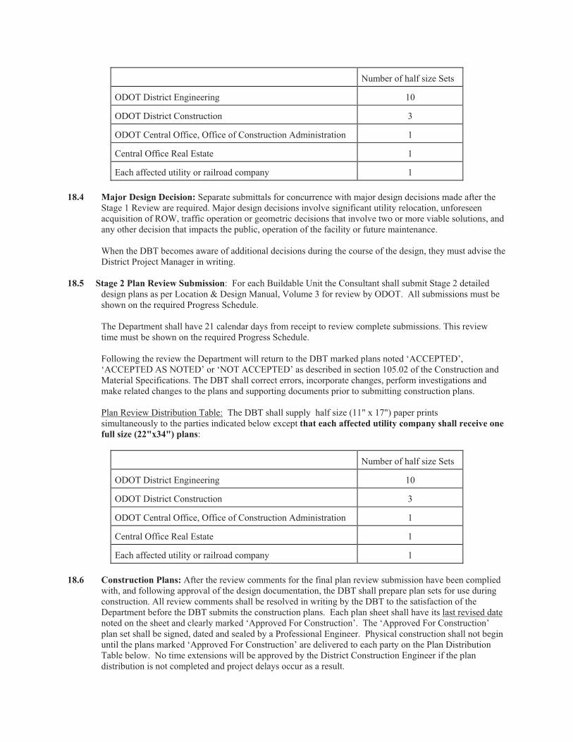
Number of half size Sets
ODOT District Engineering 10
ODOT District Construction 3
ODOT Central Office, Office of Construction Administration 1
Central Office Real Estate 1
Each affected utility or railroad company 1
18.4 Major Design Decision: Separate submittals for concurrence with major design decisions made after the Stage 1 Review are required. Major design decisions involve significant utility relocation, unforeseen acquisition of ROW, traffic operation or geometric decisions that involve two or more viable solutions, and any other decision that impacts the public, operation of the facility or future maintenance.
When the DBT becomes aware of additional decisions during the course of the design, they must advise the District Project Manager in writing.
18.5 Stage 2 Plan Review Submission: For each Buildable Unit the Consultant shall submit Stage 2 detailed design plans as per Location & Design Manual, Volume 3 for review by ODOT. All submissions must be shown on the required Progress Schedule.
The Department shall have 21 calendar days from receipt to review complete submissions. This review time must be shown on the required Progress Schedule.
Following the review the Department will return to the DBT marked plans noted ‘ACCEPTED’, ‘ACCEPTED AS NOTED’ or ‘NOT ACCEPTED’ as described in section 105.02 of the Construction and Material Specifications. The DBT shall correct errors, incorporate changes, perform investigations and make related changes to the plans and supporting documents prior to submitting construction plans.
Plan Review Distribution Table: The DBT shall supply half size (11" x 17") paper prints simultaneously to the parties indicated below except that each affected utility company shall receive one
full size (22"x34") plans:
Number of half size Sets
ODOT District Engineering 10
ODOT District Construction 3
ODOT Central Office, Office of Construction Administration 1
Central Office Real Estate 1
Each affected utility or railroad company 1
18.6 Construction Plans: After the review comments for the final plan review submission have been complied with, and following approval of the design documentation, the DBT shall prepare plan sets for use during construction. All review comments shall be resolved in writing by the DBT to the satisfaction of the Department before the DBT submits the construction plans. Each plan sheet shall have its last revised date noted on the sheet and clearly marked ‘Approved For Construction’. The ‘Approved For Construction’ plan set shall be signed, dated and sealed by a Professional Engineer. Physical construction shall not begin until the plans marked ‘Approved For Construction’ are delivered to each party on the Plan Distribution Table below. No time extensions will be approved by the District Construction Engineer if the plan distribution is not completed and project delays occur as a result.
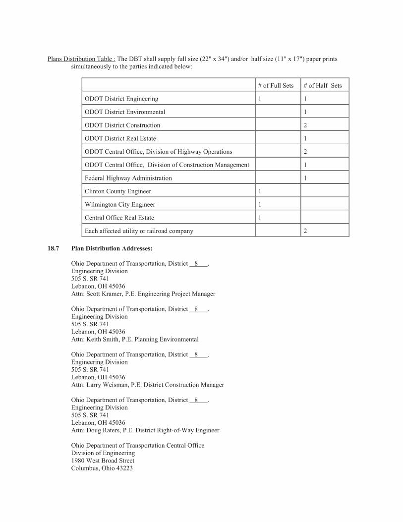
Plans Distribution Table : The DBT shall supply full size (22" x 34") and/or half size (11" x 17") paper prints simultaneously to the parties indicated below:
# of Full Sets # of Half Sets
ODOT District Engineering 1 1
ODOT District Environmental 1
ODOT District Construction 2
ODOT District Real Estate 1
ODOT Central Office, Division of Highway Operations 2
ODOT Central Office, Division of Construction Management 1
Federal Highway Administration 1
Clinton County Engineer 1
Wilmington City Engineer 1
Central Office Real Estate 1
Each affected utility or railroad company 2
18.7 Plan Distribution Addresses:
Ohio Department of Transportation, District 8 . Engineering Division 505 S. SR 741 Lebanon, OH 45036 Attn: Scott Kramer, P.E. Engineering Project Manager
Ohio Department of Transportation, District 8 . Engineering Division 505 S. SR 741 Lebanon, OH 45036 Attn: Keith Smith, P.E. Planning Environmental
Ohio Department of Transportation, District 8 . Engineering Division 505 S. SR 741 Lebanon, OH 45036 Attn: Larry Weisman, P.E. District Construction Manager
Ohio Department of Transportation, District 8 . Engineering Division 505 S. SR 741 Lebanon, OH 45036 Attn: Doug Raters, P.E. District Right-of-Way Engineer
Ohio Department of Transportation Central Office Division of Engineering 1980 West Broad Street Columbus, Ohio 43223
Attn: (James Young)
Ohio Department of Transportation Central Office Construction Administration, Division of Construction Management 1980 West Broad Street Columbus, Ohio 43223 Attn: (Gary E. Angles, P.E. Construction Administrator)
Ohio Department of Transportation Central Office Office of Real Estate 1980 West Broad Street Columbus, Ohio 43223 Attn: (John Maynard, Administrator, Office of Real Estate)
Federal Highway Administration 200 North High Street Room 328 Columbus, Ohio 43215-2408 Attn: (Mark VonderEmbse)
Ohio Department of Transportation Central Office Office of Environmental Services 1980 West Broad Street Columbus, Ohio 43223 Attn: (Tim Hill, Administrator, OES)
Clinton County Engineer’s Office 1326 Fife Avenue Wilmington, OH 45177 Attn: (Jeffery B. Linkous)
City of Wilmington City Engineer 69 N. South Street Wilmington, OH 45177 Attn: (Blankenship, Ernie)
Utility Companies (As shown in section 12)
19 BUILDABLE UNITS (BU)
Definition: Buildable Units are portions of the projects which can be designed, reviewed and built with only limited controls and assumptions coming from the design of other portions of the project. Often a Buildable Unit will be defined by a geographic area within the plan, but it may also be defined by types of work or construction stages which may require or permit similar, nearby work to be divided into separate Buildable Units. All Buildable Units shall summarize the materials required to construct that portion of the project. The summary shall include the Construction and Material Specifications Item Number, and a description of the materials to be used.
General: For the Stage 1 and Stage 2 submittals, the DBT may break the project work into two or more separate BU which can be progressed through design and construction with minimal or known effect on each other and/or which can be dealt with sequentially such that sufficient data is available for design and review of each BU. In order that the design and construction of one BU may proceed without significant approved information from an associated BU, the DBT may develop and propose assumptions which will
allow for the first BU to proceed through design and/or construction. These assumptions shall be submitted for review and comment but their accuracy and effort upon the final design are the sole responsibility of the DBT. Should error in these assumptions result in additional work, remedial work or other changes to assure an acceptable design or should they result in the need to remove work and substitute additional work, the Contractor shall be responsible for all such costs including, removal of unacceptable materials from the site, modification, additional work, repairs, etc. as necessary to produce an acceptable result.
If the DBT elects to develop Buildable Units, the DBT shall prepare, for review by the Department, a table of Buildable Units for the project with each BU described in detail. If the table is approved, the DBT shall modify the Progress Schedule to show a separate group of activities for BU and these activities shall encompass all of the design and construction work in each BU. Work activities shall be further separated in the Progress Schedule to show a meaningful completion status (i.e. separate activities comprising the placement of a bridge deck on steel beams shall describe; shoring, form building, steel placement, placement of conduit & joints, pouring concrete, forming parapets, pouring or slip forming parapets, provision of membranes, provision of wearing surfaces, curing, repair, form removal, cleaning, etc.).
The Final Review Submission and construction plans shall specifically be identified by the Buildable Unit code. If the design of a BU requires input information from an adjacent or related BU, the source for that information in previously approved plans shall be cited or the DBT shall provide an estimated value of the data. The input data shall also be carefully identified. In the same way any assumption, calculations or results from the stage and BU which are used as input to another BU shall be similarly identified, and where appropriate, compared back to that BU to verify previous assumptions. Should assumptions not match values calculated later, the DBT shall re-analyze all affected components and determine appropriate changes. Should those elements have already been constructed, the DBT shall recommend repairs, adjustments, modifications or replacement of the existing work as necessary to comply with the Scope of Work. All costs for re-design, re-submissions, modifications, removals, disposal of materials and new work needed to remedy the project and bring it to compliance shall be borne by the Contractor and no time extensions shall be approved for this.
20 DIFFERING SITE CONDITIONS
104.02.B Differing Site Conditions
Revise CMS on page 17 as follows:
104.02B Differing Site Conditions. Notify the Engineer as specified in C&MS 104.05 upon discovery of any of the following conditions:
1. Subsurface or latent physical conditions at the site differing materialy from those indicated in the Contract Documents and are not discoverable from an insvestigation and analysis of the site by the DBT meeting the standard care for such an investigation and analysis.
2. Unknown physical conditions of an unusual nature differing materially from those ordinarily encountered and generally recognized as inherent in the Work provided for in the Contract Documents, are encountered at the site. Provide required notification before disturbing any differing site conditions.
Irrespective of the previous paragraph, work involving utility relocations or utility coordination will not be considered a Differing Site Condition. This work is addressed in accordance with the Project Scope, Section 12.
Upon notification from the DBT, the Engineer will investigate potential differing site conditions. The Engineer will determine if differing site conditions have been encountered and notify the DBT of the Department’s determination.
If the Department determines that conditions materially differ and cause an increase or decrease in the cost or time required for the performance of any Work under the Contract, the Department will make an adjustment and modify the Contract as specified in CMS 109.05 and as follows:

1. The first $50,000 of the direct costs associated impact will be the responsibility of the DBT. 2. All costs which exceed the amount identified in item#1 above will be computed and paid to the DBT
without any mark-up.
Department acknowledged differing site condition Work is excusable, compensable, as defined by CMS 108.06D except as noted in this section.
21 INDEX OF ATTACHMENTS
ATTACHEMNT “A”: STAY-IN-PLACE METAL FORMS
ATTACHEMNT “B”: PEDESTRIAN PATH DRAWING
ATTACHMENT “C”: STRUCTURE FOUNDATION EXPLORATION
ATTACHMENT “D”: SUBSURFACE UTILITY EXPLORATION (SUE) PLANS AND RECORD DOCUMENTS
ATTACHMENT “E”: CONTRACT REQUIREMENTS FOR RIGHT OF WAY SERVICES
ATTACHMENT “F”: DOCUMENTS NEEDED FOR ACQUISITION BILLING PACKAGES
ATTACHMENT “G”: RECORDS FILE STANDARDIZATION PROCESS
ATTACHMENT “H”: MAXIMUM PROJECT WORK LIMITS DRAWING
ATTACHMENT “A”
STAY-IN-PLACE METAL FORMS
Description. In addition to the work requirements of 511, either provide traditional bridge deck forms conforming to CMS 508 or design, build, provide and construct galvanized steel Stay-In-Place (SIP) fabricated metal forms conforming to CMS 508 and these additional requirements.
Design, build, construct and remove SIP or removable forms at overhangs, and within eight feet of all expansion joints and four feet of all through deck drainage systems.
Design. Submit Construction Plans according to 501.05.B.3. Design SIP forms to support the self weight of SIP forms, reinforcement, wet concrete for the deck, any construction equipment loads, and at least a 50 PSF load for construction live loads. Meet the deflection requirements of 508.
Design SIP forms that have the depth of the form corrugation filled with Concrete .
Include the following information in the construction plan:
A. Design calculations.
B. Physical properties of the SIP forms ( gage, section modulus, weight, depth and pitch)
C. Cross section view and dimensions of: SIP forms, support angles, channel closures, safety stops, clips, plates and hardware.
D. Include An Overall layout plan with 1.Working points or control elevations necessary to set support angles. 2.Typical and specific cross sections or details: Support connections to the structural members, SIP form connections to supports, form laps and closure sections. 3.Minimum bearing lengths (edge distances) of SIP forms to the support angles. 4.Welding details: size, length, locations, electrodes and process.
E. Worker safety restrictions.
F. Installation inspection check lists.
Materials. Submit 501.06 Test Reports and written acceptance letters to the Engineer. Materials inspection and acceptance is performed by the Engineer at the project site. Furnish form, support materials and hardware conforming the following:
A. Form and support material, ASTM A653 having a coating designation of G235, and conforming to the mechanical properties the design requires.
B. Provide deck forms with a 2 inch minimum form depth.
C. Provide minimum material thickness as follows: SIP forms ( 20 gage), Support angles(12 gage) and Support bars (12 gage).
D. Supply deck, self drilling fasteners with Cadmium plating per ASTM B766 with minimum thickness of 5, ten thousandths.( 0.0005 inch). The heads of these fasteners will be a highly visible color, red or other, to aid inspection.
Welding. Do not weld SIP forms or their supports to the steel bridge members. SIP Supports may be welded to anchors cast into precast concrete bridge members. Perform welding per 513.21
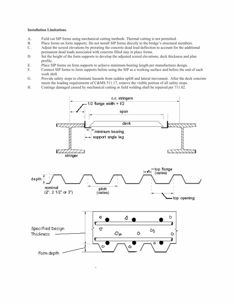
Installation Limitations.
A. Field cut SIP forms using mechanical cutting methods. Thermal cutting is not permitted. B. Place forms on form supports. Do not install SIP forms directly to the bridge’s structural members. C. Adjust the screed elevations by prorating the concrete dead load deflection to account for the additional
permanent dead loads associated with concrete filled stay in place forms. D. Set the height of the form supports to develop the adjusted screed elevations, deck thickness and plan
profile. E. Place SIP forms on form supports to achieve minimum bearing length per manufactures design. F. Connect SIP forms to form supports before using the SIP as a working surface and before the end of each
work shift. G. Provide safety stops to eliminate hazards from sudden uplift and lateral movement. After the deck concrete
meets the loading requirements of C&MS 511.17, remove the visible portion of all safety stops. H. Coatings damaged caused by mechanical cutting or field welding shall be repaired per 711.02.

Inspection. The Engineer will check SIP materials meet design requirements and evaluate installation based on construction plan.
Basis of Payment. The department will not separately pay for SIP forms. The cost of this work is included for payment in the price bid for the item for which the SIP forms are used.
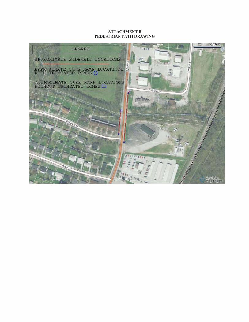
ATTACHMENT B
PEDESTRIAN PATH DRAWING