Embed Size (px)
Citation preview
13135 Danielson Street, Suite 204 Poway, CA 92064
ODOR CONTROL
1
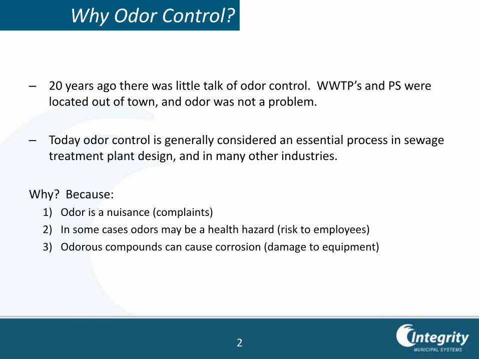
– 20 years ago there was little talk of odor control. WWTP’s and PS were located out of town, and odor was not a problem.
– Today odor control is generally considered an essential process in sewage treatment plant design, and in many other industries.
Why? Because:
1) Odor is a nuisance (complaints)
2) In some cases odors may be a health hazard (risk to employees)
3) Odorous compounds can cause corrosion (damage to equipment)
Why Odor Control?
2
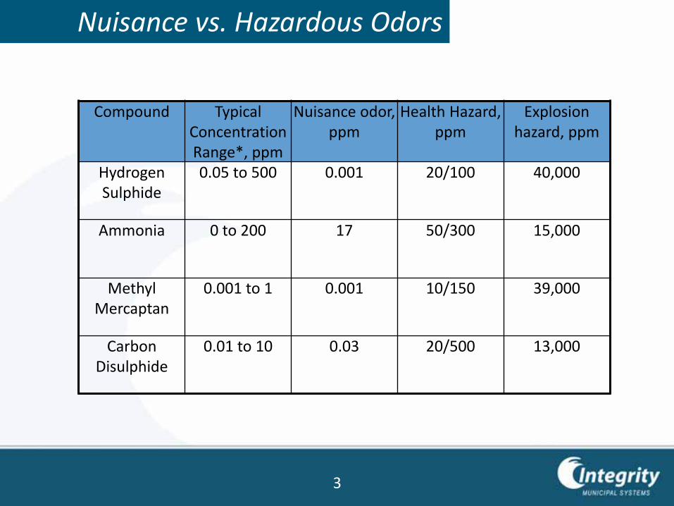
Nuisance vs. Hazardous Odors
Compound Typical Concentration Range*, ppm
Nuisance odor, ppm
Health Hazard, ppm
Explosion hazard, ppm
Hydrogen Sulphide
0.05 to 500 0.001 20/100 40,000
Ammonia 0 to 200 17 50/300 15,000
Methyl Mercaptan
0.001 to 1 0.001 10/150 39,000
Carbon Disulphide
0.01 to 10 0.03 20/500 13,000
3
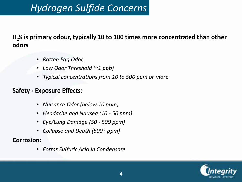
Hydrogen Sulfide Concerns
H2S is primary odour, typically 10 to 100 times more concentrated than other odors
• Rotten Egg Odor,
• Low Odor Threshold (~1 ppb)
• Typical concentrations from 10 to 500 ppm or more
Safety - Exposure Effects:
• Nuisance Odor (below 10 ppm)
• Headache and Nausea (10 - 50 ppm)
• Eye/Lung Damage (50 - 500 ppm)
• Collapse and Death (500+ ppm)
Corrosion:
• Forms Sulfuric Acid in Condensate
4
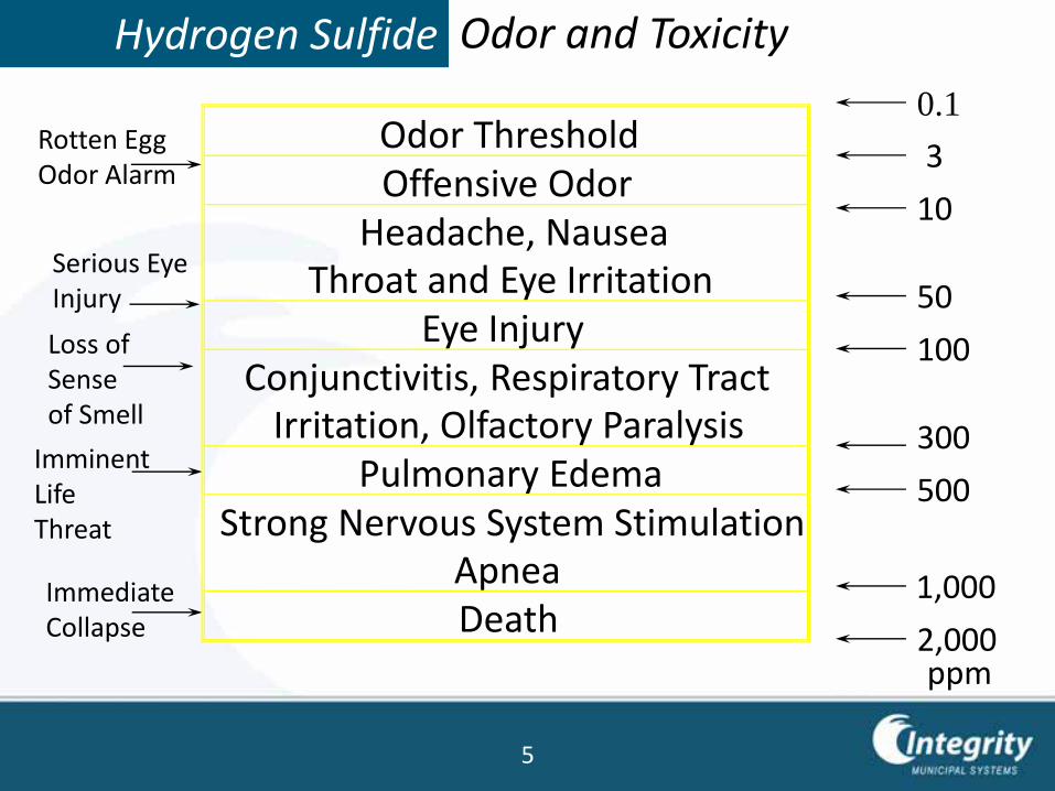
Hydrogen Sulfide Odor and Toxicity
ppm
0.1
3
10
50
100
300
500
1,000
2,000
Rotten EggOdor Alarm
Serious EyeInjury
Loss of Sense of Smell
ImminentLifeThreat
ImmediateCollapse
Odor ThresholdOffensive Odor
Headache, NauseaThroat and Eye Irritation
Eye InjuryConjunctivitis, Respiratory Tract
Irritation, Olfactory ParalysisPulmonary Edema
Strong Nervous System StimulationApneaDeath
5
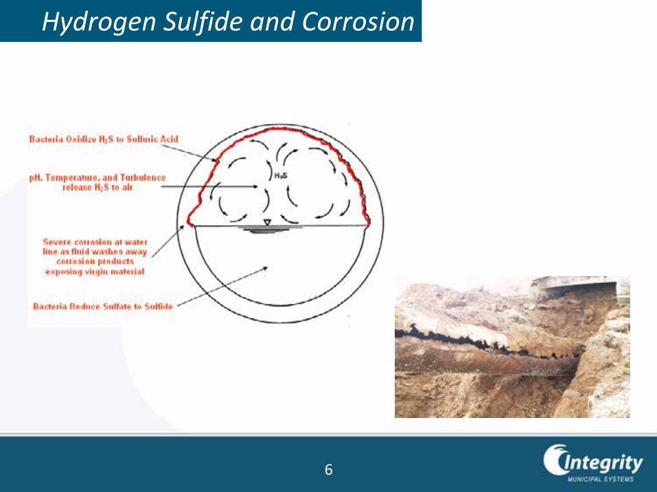
Hydrogen Sulfide and Corrosion
6
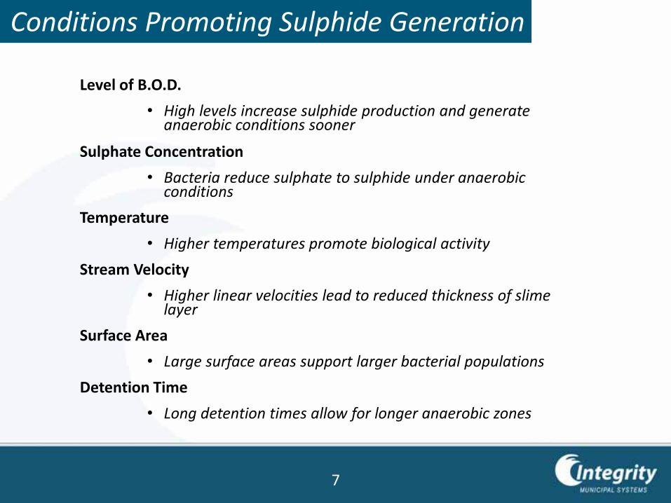
Level of B.O.D.
• High levels increase sulphide production and generate anaerobic conditions sooner
Sulphate Concentration
• Bacteria reduce sulphate to sulphide under anaerobic conditions
Temperature
• Higher temperatures promote biological activity
Stream Velocity
• Higher linear velocities lead to reduced thickness of slime layer
Surface Area
• Large surface areas support larger bacterial populations
Detention Time
• Long detention times allow for longer anaerobic zones
Conditions Promoting Sulphide Generation
7
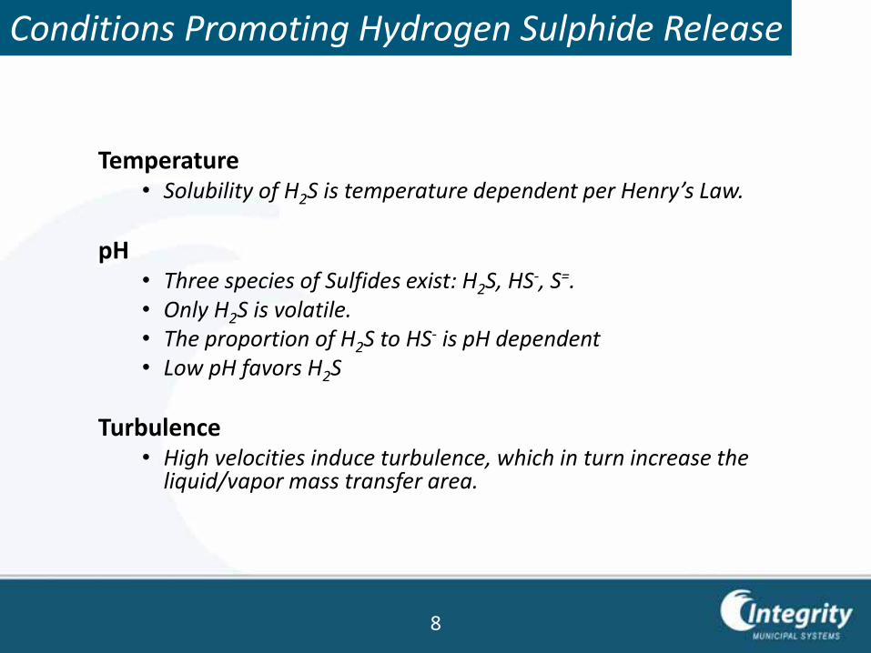
Temperature• Solubility of H2S is temperature dependent per Henry’s Law.
pH• Three species of Sulfides exist: H2S, HS-, S=.• Only H2S is volatile.• The proportion of H2S to HS- is pH dependent• Low pH favors H2S
Turbulence • High velocities induce turbulence, which in turn increase the
liquid/vapor mass transfer area.
8
Conditions Promoting Hydrogen Sulphide Release
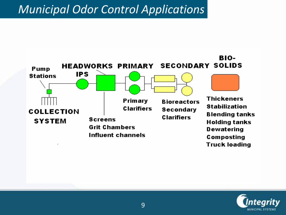
Municipal Odor Control Applications
9
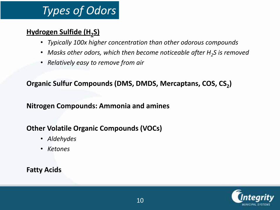
Types of Odors
Hydrogen Sulfide (H2S)
• Typically 100x higher concentration than other odorous compounds
• Masks other odors, which then become noticeable after H2S is removed
• Relatively easy to remove from air
Organic Sulfur Compounds (DMS, DMDS, Mercaptans, COS, CS2)
Nitrogen Compounds: Ammonia and amines
Other Volatile Organic Compounds (VOCs)
• Aldehydes
• Ketones
Fatty Acids
10
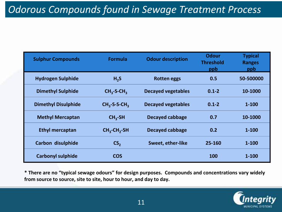
Sulphur Compounds Formula Odour descriptionOdour
ThresholdTypical Ranges
ppb ppb
Hydrogen Sulphide H2S Rotten eggs 0.5 50-500000
Dimethyl Sulphide CH3-S-CH3 Decayed vegetables 0.1-2 10-1000
Dimethyl Disulphide CH3-S-S-CH3 Decayed vegetables 0.1-2 1-100
Methyl Mercaptan CH3-SH Decayed cabbage 0.7 10-1000
Ethyl mercaptan CH3-CH2-SH Decayed cabbage 0.2 1-100
Carbon disulphide CS2 Sweet, ether-like 25-160 1-100
Carbonyl sulphide COS 100 1-100
* There are no “typical sewage odours” for design purposes. Compounds and concentrations vary widelyfrom source to source, site to site, hour to hour, and day to day.
11
Odorous Compounds found in Sewage Treatment Process
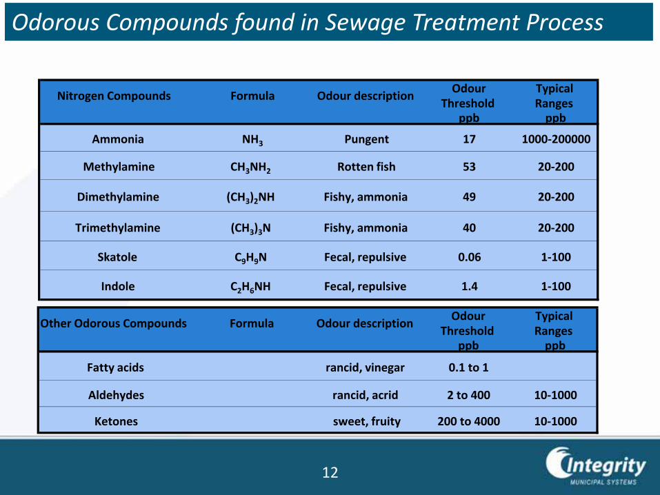
Nitrogen Compounds Formula Odour descriptionOdour
ThresholdTypical Ranges
ppb ppb
Ammonia NH3 Pungent 17 1000-200000
Methylamine CH3NH2 Rotten fish 53 20-200
Dimethylamine (CH3)2NH Fishy, ammonia 49 20-200
Trimethylamine (CH3)3N Fishy, ammonia 40 20-200
Skatole C9H9N Fecal, repulsive 0.06 1-100
Indole C2H6NH Fecal, repulsive 1.4 1-100
Other Odorous Compounds Formula Odour descriptionOdour
ThresholdTypical Ranges
ppb ppb
Fatty acids rancid, vinegar 0.1 to 1
Aldehydes rancid, acrid 2 to 400 10-1000
Ketones sweet, fruity 200 to 4000 10-1000
12
Odorous Compounds found in Sewage Treatment Process
About VOC’s
• Volatile Organic Compounds (VOCs) are a large group of carbon-based chemicals that easily evaporate at room temperature. While some VOCs are odorous, many other VOCs are not. There are thousands of different VOCs produced and used in our daily lives.
• In sewage treatment the odorous VOC’s are primarily amines, organic sulfides, mercaptans and some organic acids.
• Hydrocarbons are VOC’s that are regulated because they contribute to photochemical smog. Although many are odorous, they are not generally a major contributor to municipal odors.
• Control of hydrocarbons requires very different technology from control of sewage odors.
13
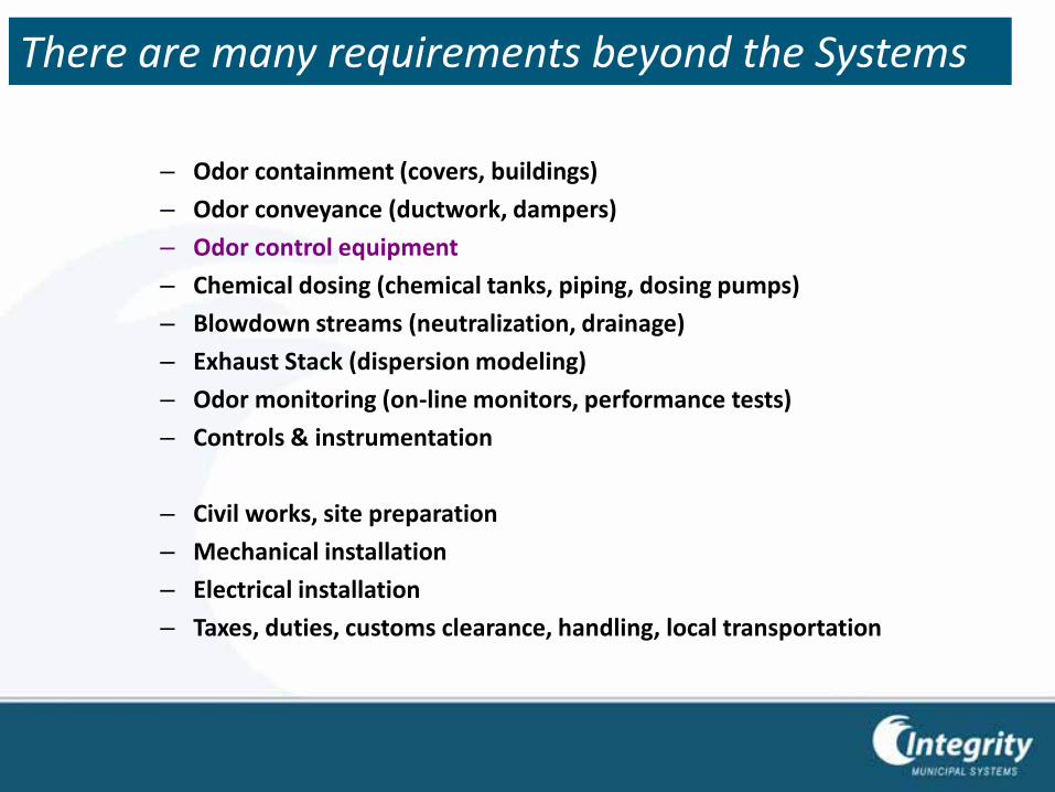
– Odor containment (covers, buildings)
– Odor conveyance (ductwork, dampers)
– Odor control equipment
– Chemical dosing (chemical tanks, piping, dosing pumps)
– Blowdown streams (neutralization, drainage)
– Exhaust Stack (dispersion modeling)
– Odor monitoring (on-line monitors, performance tests)
– Controls & instrumentation
– Civil works, site preparation
– Mechanical installation
– Electrical installation
– Taxes, duties, customs clearance, handling, local transportation
There are many requirements beyond the Systems
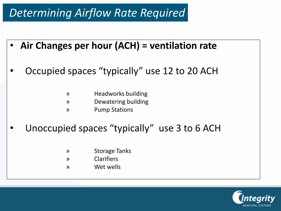
• Air Changes per hour (ACH) = ventilation rate
• Occupied spaces “typically” use 12 to 20 ACH
» Headworks building» Dewatering building» Pump Stations
• Unoccupied spaces “typically” use 3 to 6 ACH
» Storage Tanks» Clarifiers» Wet wells
Determining Airflow Rate Required
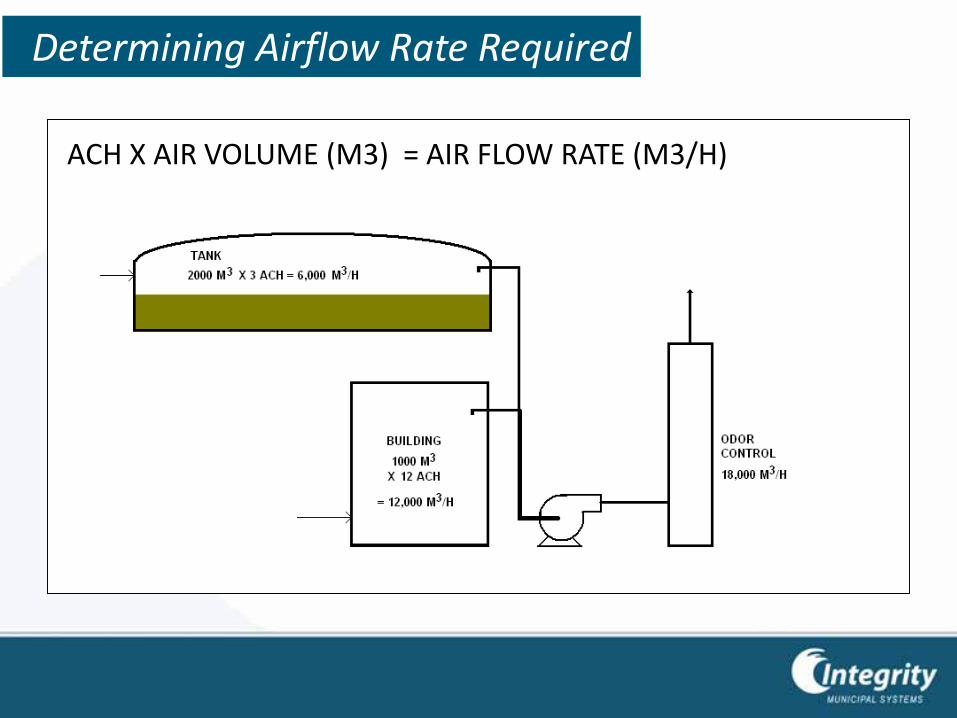
ACH X AIR VOLUME (M3) = AIR FLOW RATE (M3/H)
Determining Airflow Rate Required
Localized OC vs. Centralized OC
LOCALIZED ODOR CONTROL uses several smaller odor control systems located near each odor source. Sizes and technology may vary from one location to another.
• Eliminates complex ductwork and air flow balancing
• Can use smaller and more focused technology for each source
• Easy to install
CENTRALIZED ODOR CONTROL uses ductwork to convey odors from odor sources to common central odor control system.
• Allows easier redundancy
• Common parts
• Simpler maintenance
17
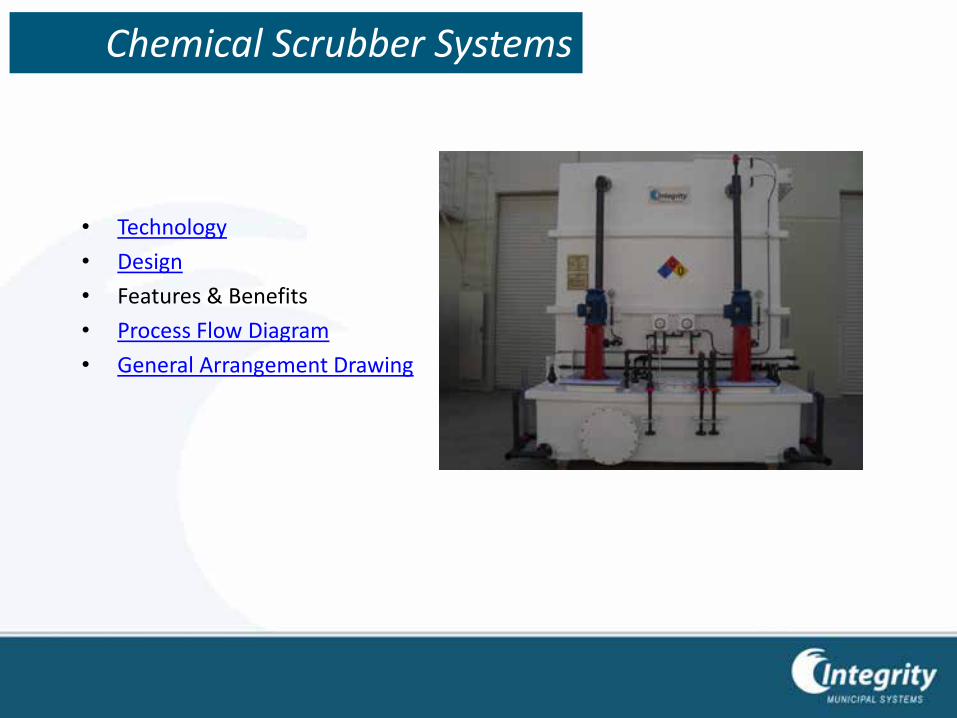
• Technology
• Design
• Features & Benefits
• Process Flow Diagram
• General Arrangement Drawing
Chemical Scrubber Systems
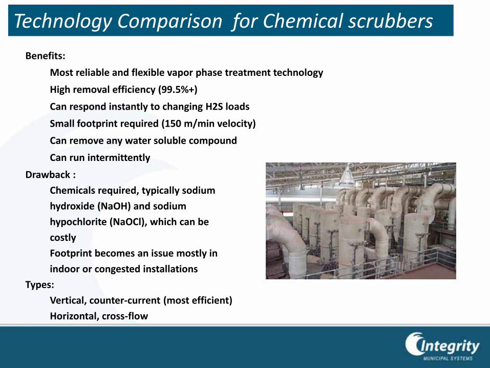
Benefits:
Most reliable and flexible vapor phase treatment technology
High removal efficiency (99.5%+)
Can respond instantly to changing H2S loads
Small footprint required (150 m/min velocity)
Can remove any water soluble compound
Can run intermittently
Drawback :
Chemicals required, typically sodium
hydroxide (NaOH) and sodium
hypochlorite (NaOCl), which can be
costly
Footprint becomes an issue mostly in
indoor or congested installations
Types:
Vertical, counter-current (most efficient)
Horizontal, cross-flow
Technology Comparison for Chemical scrubbers
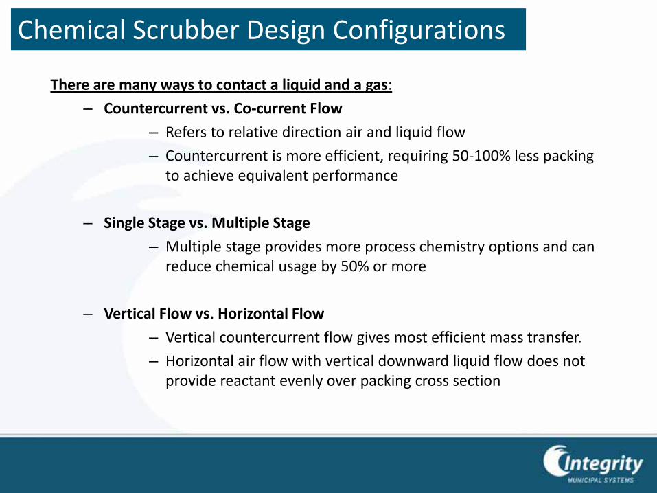
There are many ways to contact a liquid and a gas:
– Countercurrent vs. Co-current Flow
– Refers to relative direction air and liquid flow
– Countercurrent is more efficient, requiring 50-100% less packing to achieve equivalent performance
– Single Stage vs. Multiple Stage
– Multiple stage provides more process chemistry options and can reduce chemical usage by 50% or more
– Vertical Flow vs. Horizontal Flow
– Vertical countercurrent flow gives most efficient mass transfer.
– Horizontal air flow with vertical downward liquid flow does not provide reactant evenly over packing cross section
Chemical Scrubber Design Configurations
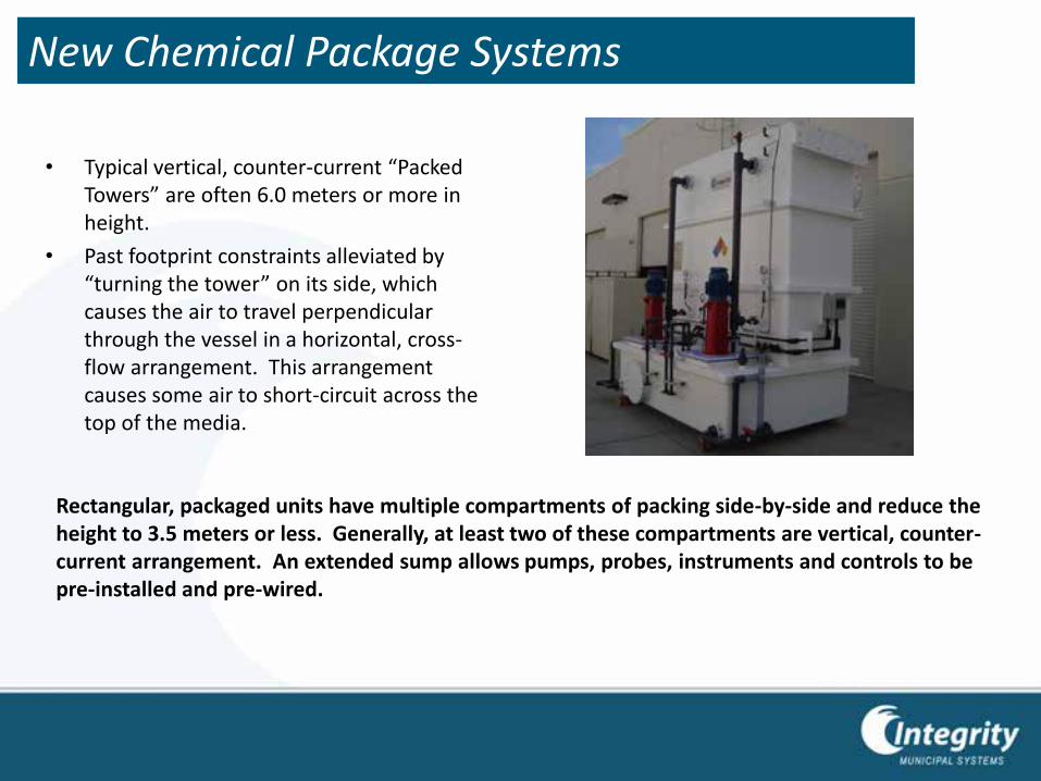
• Typical vertical, counter-current “Packed Towers” are often 6.0 meters or more in height.
• Past footprint constraints alleviated by “turning the tower” on its side, which causes the air to travel perpendicular through the vessel in a horizontal, cross-flow arrangement. This arrangement causes some air to short-circuit across the top of the media.
Rectangular, packaged units have multiple compartments of packing side-by-side and reduce the height to 3.5 meters or less. Generally, at least two of these compartments are vertical, counter-current arrangement. An extended sump allows pumps, probes, instruments and controls to be pre-installed and pre-wired.
New Chemical Package Systems
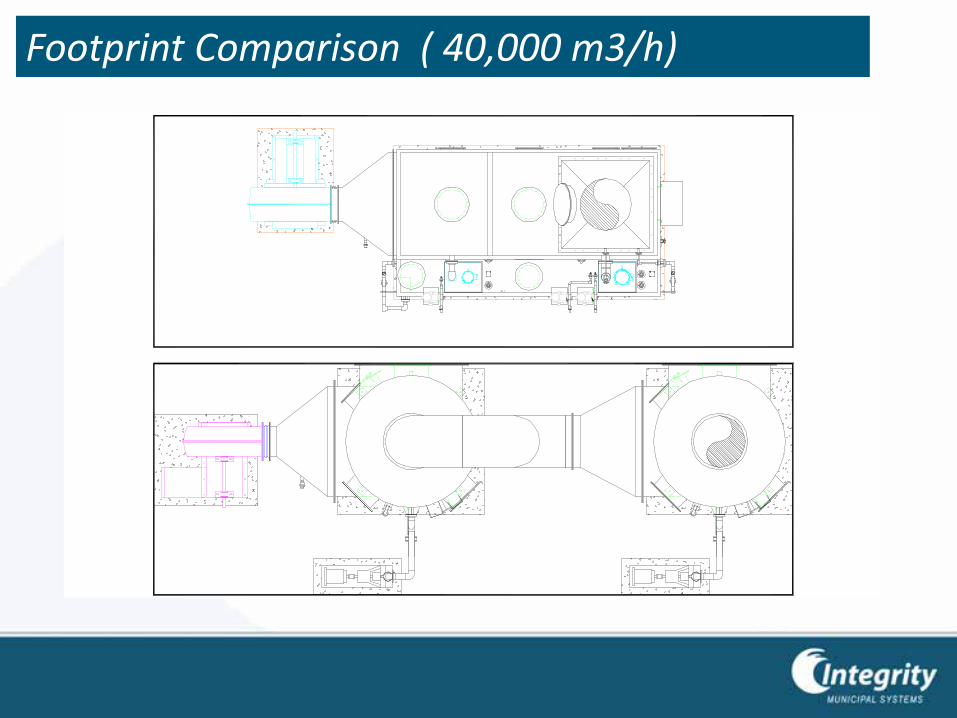
Footprint Comparison ( 40,000 m3/h)
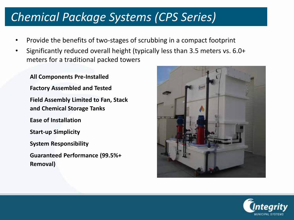
• Provide the benefits of two-stages of scrubbing in a compact footprint
• Significantly reduced overall height (typically less than 3.5 meters vs. 6.0+ meters for a traditional packed towers
All Components Pre-Installed
Factory Assembled and Tested
Field Assembly Limited to Fan, Stack
and Chemical Storage Tanks
Ease of Installation
Start-up Simplicity
System Responsibility
Guaranteed Performance (99.5%+
Removal)
Chemical Package Systems (CPS Series)
• Pre-treatment stage eliminates approximately 70% of odors using a less expensive chemical
• Complete utilization of chemicals prior to discharge with multiple sumps
• Counter-current chemistry
• Optimal process control
Minimal Chemical Consumption
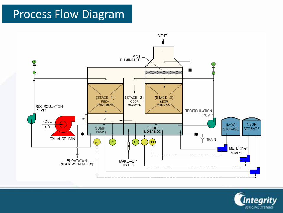
Process Flow Diagram
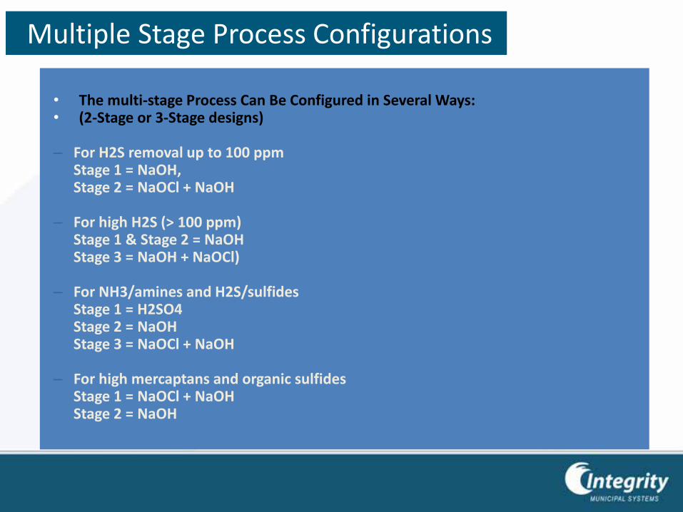
• The multi-stage Process Can Be Configured in Several Ways:• (2-Stage or 3-Stage designs)
– For H2S removal up to 100 ppmStage 1 = NaOH, Stage 2 = NaOCl + NaOH
– For high H2S (> 100 ppm)Stage 1 & Stage 2 = NaOHStage 3 = NaOH + NaOCl)
– For NH3/amines and H2S/sulfidesStage 1 = H2SO4Stage 2 = NaOHStage 3 = NaOCl + NaOH
– For high mercaptans and organic sulfidesStage 1 = NaOCl + NaOHStage 2 = NaOH
Multiple Stage Process Configurations
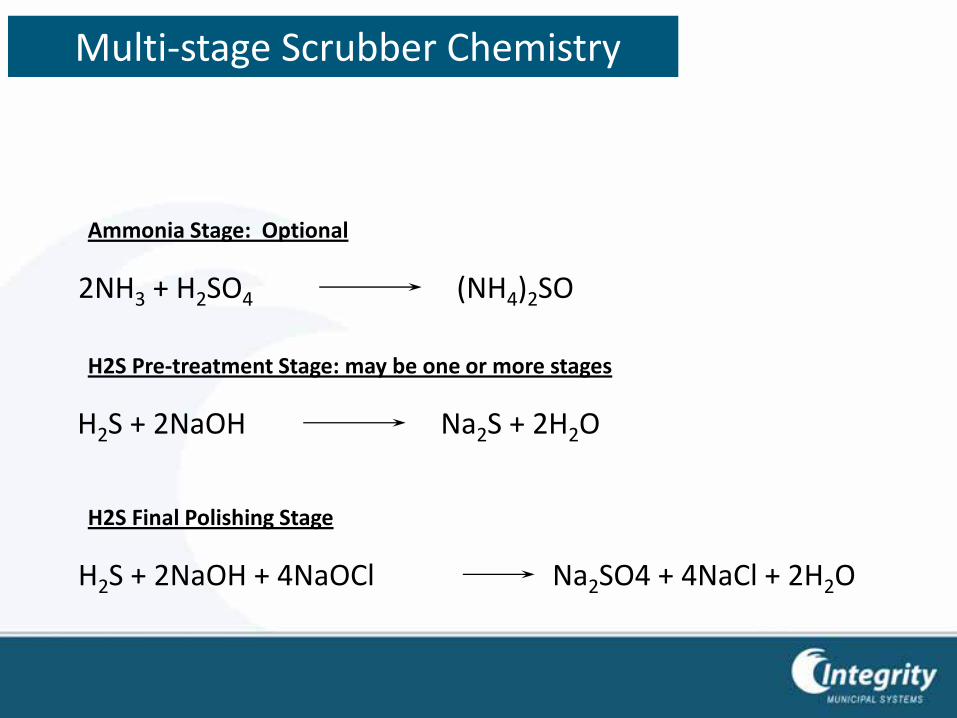
H2S + 2NaOH Na2S + 2H2O
H2S + 2NaOH + 4NaOCl Na2SO4 + 4NaCl + 2H2O
2NH3 + H2SO4 (NH4)2SO
Ammonia Stage: Optional
H2S Final Polishing Stage
H2S Pre-treatment Stage: may be one or more stages
Multi-stage Scrubber Chemistry
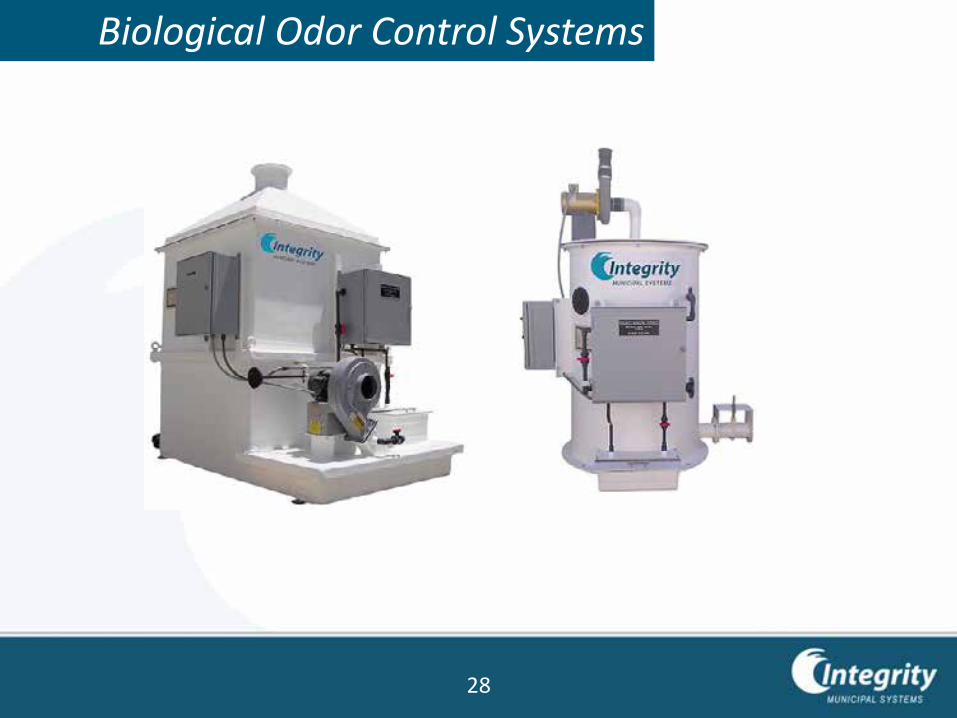
Biological Odor Control Systems
28
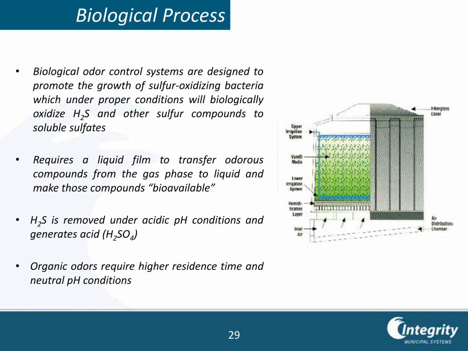
Biological Process
• Biological odor control systems are designed topromote the growth of sulfur-oxidizing bacteriawhich under proper conditions will biologicallyoxidize H2S and other sulfur compounds tosoluble sulfates
• Requires a liquid film to transfer odorouscompounds from the gas phase to liquid andmake those compounds “bioavailable”
• H2S is removed under acidic pH conditions andgenerates acid (H2SO4)
• Organic odors require higher residence time andneutral pH conditions
29
Requirements of Sulfur-Oxidizing Bacteria
• Energy source:– H2S and other sulfur compounds
• Carbon source:– Organic matter (heterotrophic bacteria)
– Carbon dioxide (autotrophic bacteria)
• Nutrients: nitrate, phosphate, potassium
• Water
• Oxygen (H2S + O2 → H2SO4)
• Temperature (10 to 50oC)
• Time (for absorption and reaction)
30
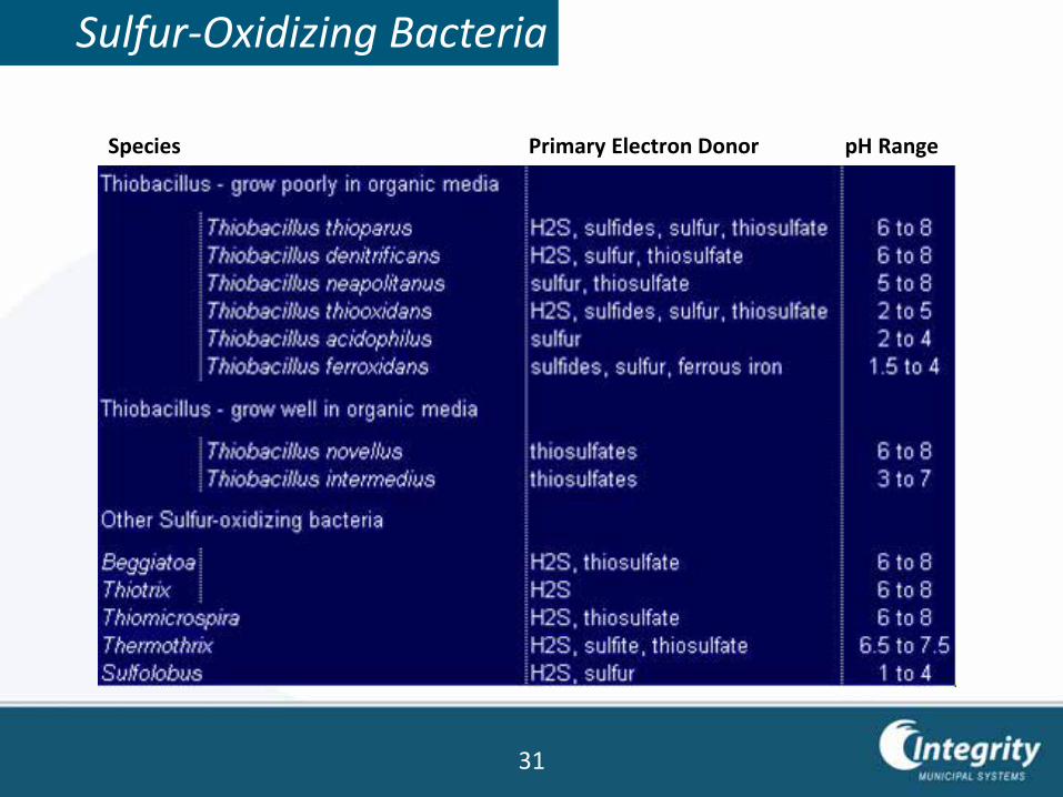
Sulfur-Oxidizing Bacteria
Species Primary Electron Donor pH Range
31
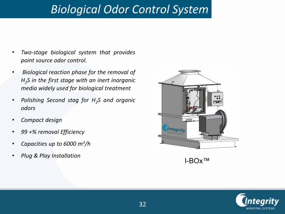
Biological Odor Control System
I-BOx™
• Two-stage biological system that provides
point source odor control.
• Biological reaction phase for the removal of
H2S in the first stage with an inert inorganic
media widely used for biological treatment
• Polishing Second stag for H2S and organic
odors
• Compact design
• 99 +% removal Efficiency
• Capacities up to 6000 m3/h
• Plug & Play Installation
32
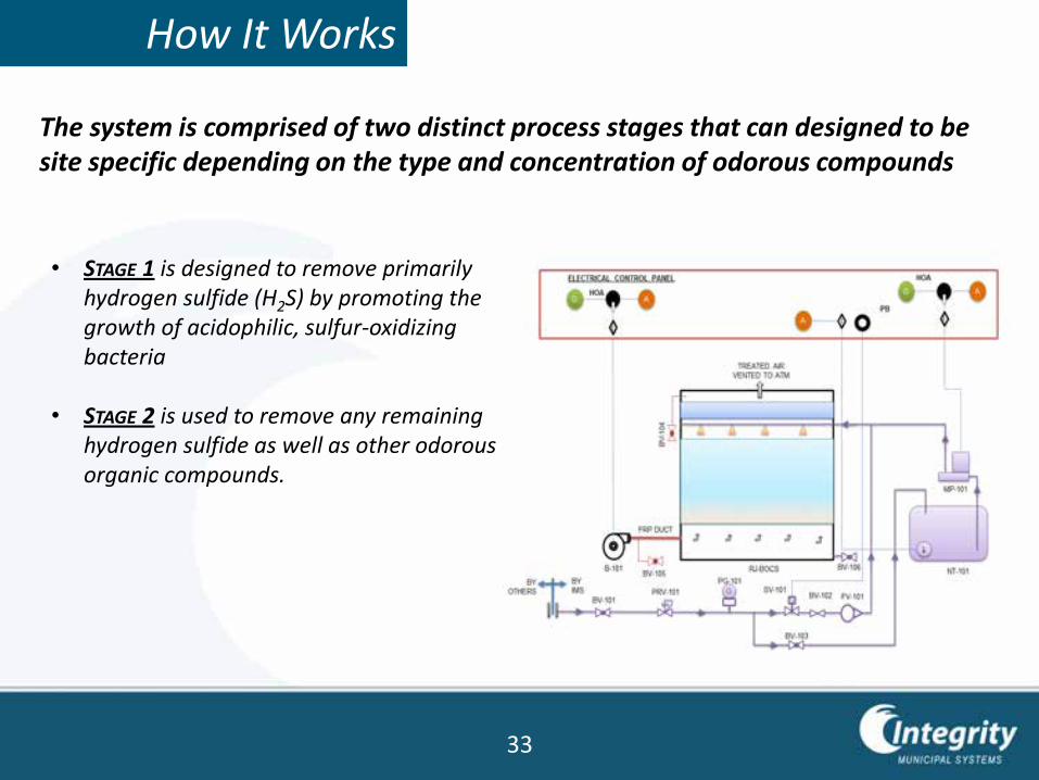
How It Works
• STAGE 1 is designed to remove primarily hydrogen sulfide (H2S) by promoting the growth of acidophilic, sulfur-oxidizing bacteria
• STAGE 2 is used to remove any remaining hydrogen sulfide as well as other odorous organic compounds.
The system is comprised of two distinct process stages that can designed to be site specific depending on the type and concentration of odorous compounds
33
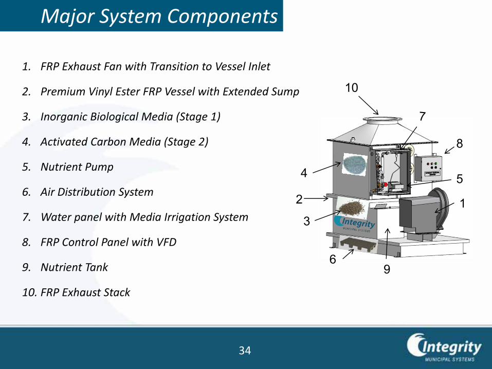
Major System Components
1. FRP Exhaust Fan with Transition to Vessel Inlet
2. Premium Vinyl Ester FRP Vessel with Extended Sump
3. Inorganic Biological Media (Stage 1)
4. Activated Carbon Media (Stage 2)
5. Nutrient Pump
6. Air Distribution System
7. Water panel with Media Irrigation System
8. FRP Control Panel with VFD
9. Nutrient Tank
10. FRP Exhaust Stack
12
4 5
8
9
3
6
10
34
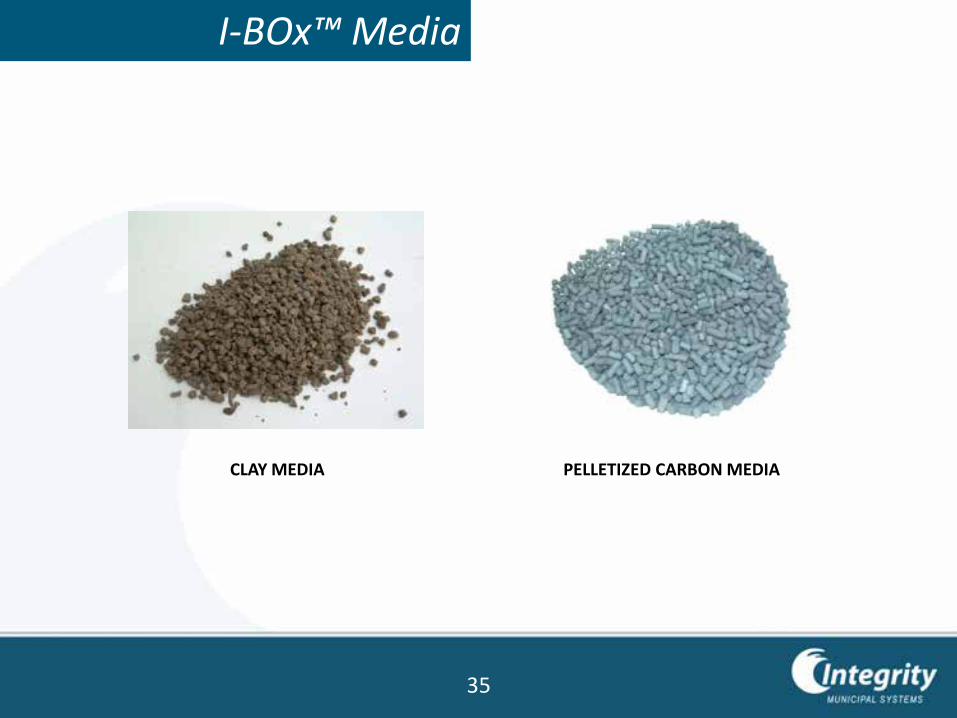
I-BOx™ Media
CLAY MEDIA PELLETIZED CARBON MEDIA
35
I-BOx™ Advantages
• High air flow rate (~450 m3/h per m2, compared to 100 m3/h per m2 for
conventional organic biofilters)
• Inorganic media biofilter long media life, preferential development of
autotrophic bacteria
• Quick acclimation specialized media adsorbs odors during acclimation period,
for immediate H2S removal
• Targets inorganic (H2S) and organic odors
• Compact Footprint
• Skid mounted for easy, low cost installation
• Low Operating Cost
36
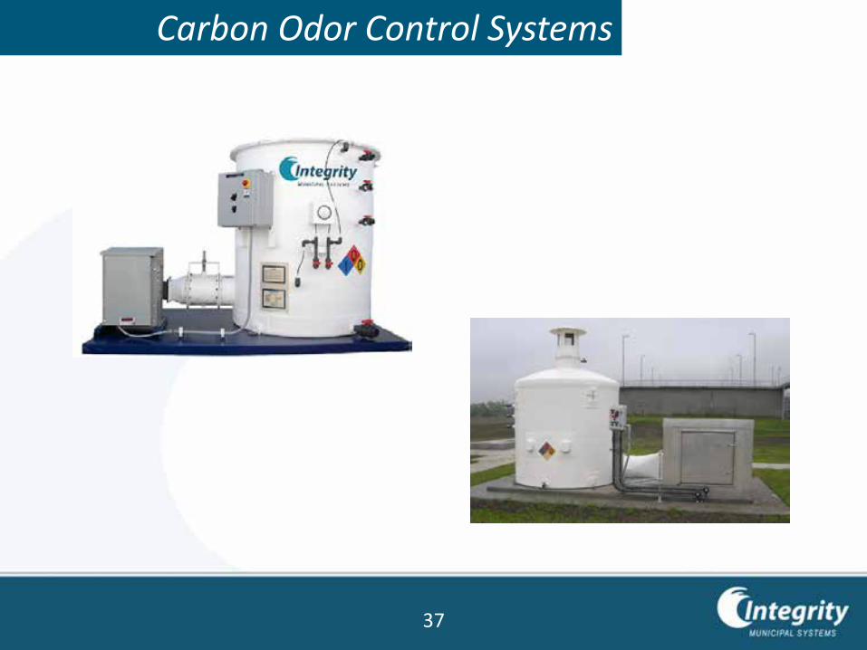
Carbon Odor Control Systems
37
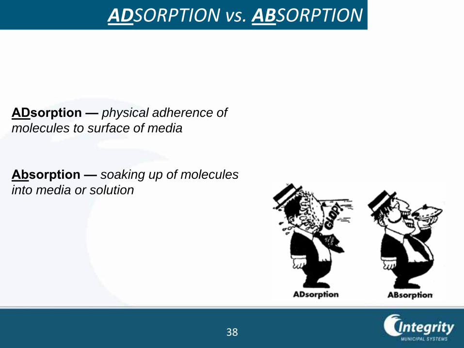
ADSORPTION vs. ABSORPTION
ADsorption — physical adherence of
molecules to surface of media
Absorption — soaking up of molecules
into media or solution
38
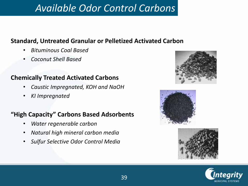
Available Odor Control Carbons
Standard, Untreated Granular or Pelletized Activated Carbon
• Bituminous Coal Based
• Coconut Shell Based
Chemically Treated Activated Carbons
• Caustic Impregnated, KOH and NaOH
• KI Impregnated
“High Capacity” Carbons Based Adsorbents
• Water regenerable carbon
• Natural high mineral carbon media
• Sulfur Selective Odor Control Media
39
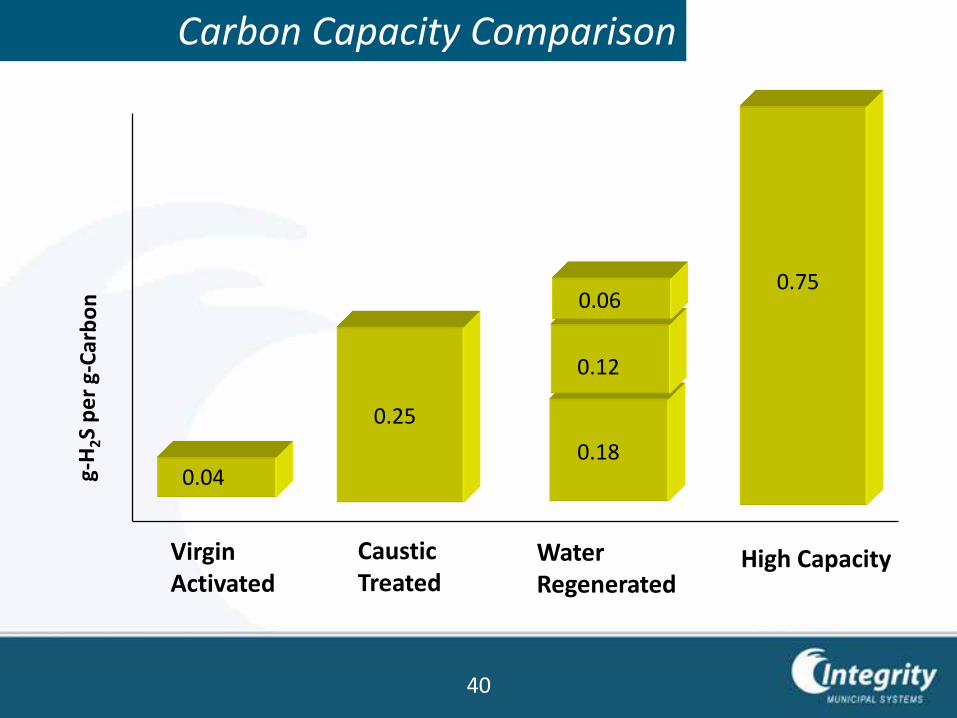
Carbon Capacity Comparison
0.04
0.25
Virgin Activated
Caustic Treated
Water Regenerated
High Capacity
0.75
0.18
0.12
0.06
40
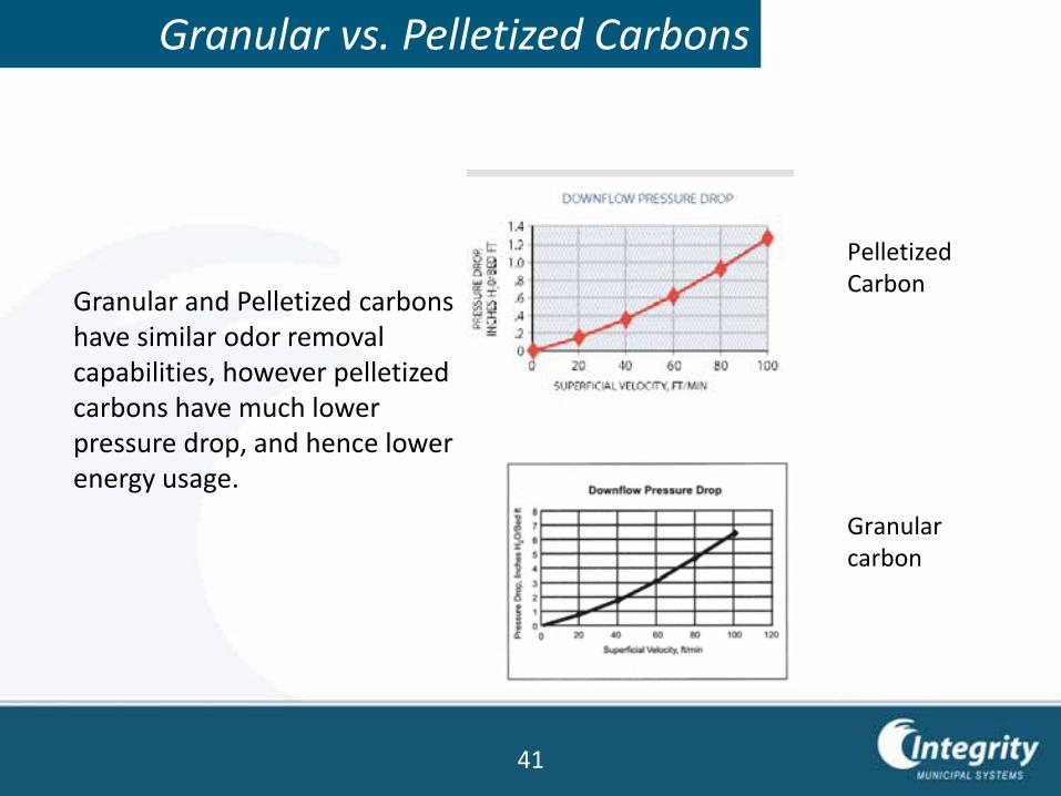
Granular vs. Pelletized Carbons
Granular and Pelletized carbons have similar odor removal capabilities, however pelletized carbons have much lower pressure drop, and hence lower energy usage.
Pelletized Carbon
Granular carbon
41
Factors That Influence the Carbon Loading Capacity
• Relative Humidity
• Temperature
• Contaminant Properties
• Contaminant Concentration
• Pressure (Vacuum)
• Gas Flow Rate (EBCT) and Superficial Velocity
• Heat of Adsorption
• System Configuration
42
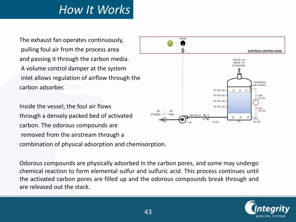
How It Works
The exhaust fan operates continuously,
pulling foul air from the process area
and passing it through the carbon media.
A volume control damper at the system
inlet allows regulation of airflow through the
carbon adsorber.
Inside the vessel, the foul air flows
through a densely packed bed of activated
carbon. The odorous compounds are
removed from the airstream through a
combination of physical adsorption and chemisorption.
Odorous compounds are physically adsorbed in the carbon pores, and some may undergochemical reaction to form elemental sulfur and sulfuric acid. This process continues untilthe activated carbon pores are filled up and the odorous compounds break through andare released out the stack.
43
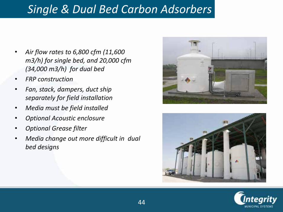
Single & Dual Bed Carbon Adsorbers
• Air flow rates to 6,800 cfm (11,600 m3/h) for single bed, and 20,000 cfm(34,000 m3/h) for dual bed
• FRP construction
• Fan, stack, dampers, duct ship separately for field installation
• Media must be field installed
• Optional Acoustic enclosure
• Optional Grease filter
• Media change out more difficult in dual bed designs
44
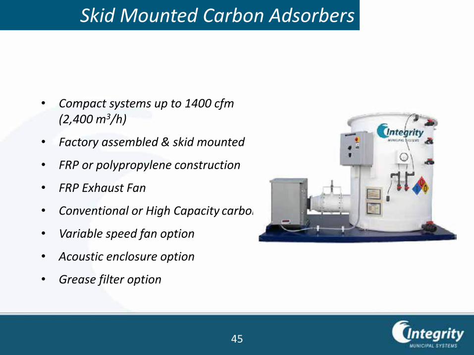
Skid Mounted Carbon Adsorbers
• Compact systems up to 1400 cfm(2,400 m3/h)
• Factory assembled & skid mounted
• FRP or polypropylene construction
• FRP Exhaust Fan
• Conventional or High Capacity carbon
• Variable speed fan option
• Acoustic enclosure option
• Grease filter option
45
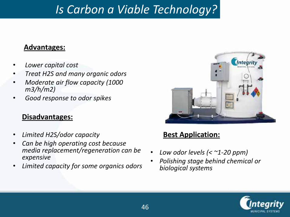
Is Carbon a Viable Technology?
Advantages:
• Lower capital cost• Treat H2S and many organic odors• Moderate air flow capacity (1000
m3/h/m2)• Good response to odor spikes
Disadvantages:
• Limited H2S/odor capacity• Can be high operating cost because
media replacement/regeneration can be expensive
• Limited capacity for some organics odors
Best Application:
• Low odor levels (< ~1-20 ppm)• Polishing stage behind chemical or
biological systems
46
Factors to Consider
For any given application, the selection of the best technology may be based on many factors, including:
• Capital cost for Equipment
• Installed cost
• Operating cost
• Source of funding and budget
• Maintenance requirements
• Reliability
• Safety
• Performance (% removal)
• Size (footprint, height)
47
Each Technology has its Niche
There is no one technology that is best in every application. Eachtechnology has it’s niche.
Wet Chemical Scrubbers:
• Can treat larger air flows in a single vessel
• Have more compact footprint
• Are less sensitive to variations in actual vs. design H2S loadings
• And are effective for a wider range of odorous compounds (H2S, NH3, amines, organic sulfides).
48
Each Technology has its Niche
Biological Systems:
• Have very low operating and maintenance costs
• Do not require handling of hazardous chemicals.
• Operating cost is not proportional to H2S concentration (hence they are well suited to high H2S applications)
49
Each Technology has its Niche
Activated Carbon Systems:
• Are the simplest and lowest maintenance systems (until you need to change out the carbon)
• Require only electrical power to operate (no water, no chemicals)
• Are efficient for a wide range of compounds.
50
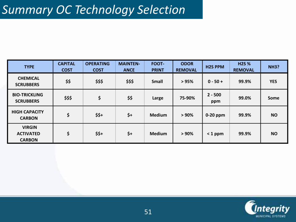
Summary OC Technology Selection
TYPECAPITAL
COST
OPERATING
COST
MAINTEN-
ANCE
FOOT-
ODOR
REMOVALH2S PPM
H2S %
REMOVALNH3?
CHEMICAL
SCRUBBERS $$ $$$ $$$ Small > 95% 0 - 50 + 99.9% YES
BIO-TRICKLING
SCRUBBERS$$$ $ $$ Large 75-90%
2 - 500
ppm99.0% Some
HIGH CAPACITY
CARBON$ $$+ $+ Medium > 90% 0-20 ppm 99.9% NO
VIRGIN
ACTIVATED
CARBON
$ $$+ $+ Medium > 90% < 1 ppm 99.9% NO
51
Applications
Information needed to select appropriate technology
• Air Flow Rate or Ventilation Rate
• H2S Concentration (average and peak)
• Required level of odor removal (H2S and OU)
• Detailed performance and equipment specifications if available
• Testing requirements
• Concentration of other odorous compounds present
• Site location
• Temperatures (ambient air and odor stream)
• Need freeze protection?
• Indoor or Outdoor location?
• Hazardous area classification?
• Local 3-phase and 1-phase voltage and Hertz
52
Contacts
Georgios Ioannou
Integrity Municipal Systems
Director of Sales EMEA
El. Venizelou 263-265
Kallithea 17673
Athens Greece
Mobile: (+30) 693 610 1300
E-mail: [email protected]
Headquarters
13135 Danielson Str.
Suite 204
Poway, CA 92064 USA
53