Embed Size (px)
Citation preview

Eurocode 3: Design of Steel StruturesPart 1‐8 : Design of Joints
1. Introduction2. Basis of Design3. Bolted Connections4. Welded Connections5. Analysis, Classification and Modelling6. Structural Joints connecting H or I sections7. Hollow section joints
BS EN 1993‐1‐8:2005

Connections, treated as structural elements Rules provided to determine the design parameters e.g. stiffness, strength and rotation capacity Connections modeled by using component‐based approach

2. Basis of Design

BOLTED CONNECTIONS
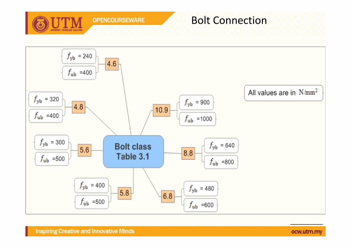
• Bolt classes 4.6, 4.8, 5.6, 5.8, 6.8, 8.8 and 10.9• Bolted connection loaded in shear should be designed as:
– Category A: Bearing type– Category B: Slip-resistant at serviceability limit state– Category C: Slip-resistant at ultimate limit state
• Bolted connection loaded in tension:– Category D: non-preloaded– Category E: preloaded
Bolt Connection

Bolt Connection

Positioning of holes


Design resistance

Design resistance : Shear resistance per shear plane

Design resistance : Bearing resistance

Definition of p1, e1, p2 and e2

Other conditions of resistance in bolt connection

Slip resistant connections

Slip resistant connections (continue)

Slip resistant connections (continue)

Deduction for fastener holes

Angles connected by one leg