Embed Size (px)
Citation preview

Use of Third Party EMC or Radio Test LaboratoriesWhat Every Company Should Gather as Part of Their Global Regulatory Compliance Management Program
Counterfeit Electronic Components
Compliance With Product Safety Standards
Fundamentals of ESDPart 3
Speed Dating 22 Airplanes from the Propeller Era
COMPLIANCE MARKETPLACE Testing Laboratories
THE COMPLIANCE INFORMATION RESOURCE FOR ELECTRICAL ENGINEERS MagazineTHE COMPLIANCE INFORMATION RESOURCE FOR ELECTRICAL ENGINEERS
OCTOBER 2010TM

October 2010 IN Compliance 3
TEST LABS DIRECTORY63
EVENTS69
24 What Every Company Should Gather as Part of Their GLOBAL REGULATORY COMPLIANCE MANAGEMENT PROGRAMPeter S. Merguerian
Novel Approaches for the Detection of COUNTERFEIT ELECTRONIC COMPONENTSJohn M. Radman and Daniel D. Phillips
COMPLIANCE WITH PRODUCT SAFETY STANDARDS as a Defense to Product Liability LitigationKenneth Ross
FUNDAMENTALS OF ELECTROSTATIC DISCHARGE Part 3: Basic ESD Control Procedures and MaterialsThe ESD Association
SPEED DATING 22 AIRPLANES from the Propeller EraDr. Brian Kent
12
NEWS IN COMPLIANCE5
THE INARTE INFORMER8
28
36
42
Use of Third Party EMC or Radio TEST LABORATORIESWerner Schaefer
BUSINESS NEWS67
WHAT’S INSIDE
LETTERS TO THE EDITOR4
THE FUTURE OF EMC ENGINEERING
41
48
SPECIAL SECTION2010 IEEE
Symposium on Product Compliance
EngineeringBoston, MA
October 18 - 20, 2010
56

Dear Editor:
Mike Violette’s article “Lightning and Miss Liberty” (IN Compliance, September 2010, pp. 17-21) was both entertaining and informative. At one point he speculates on why lightning should ever strike the lower parts of the Statue, such as the tablet and even the skirt. One would think that the torch and crown, being highest, and hence closest to the charged cloud would offer the preferred breakdown path. A plausible hypothesis is that high energy cosmic rays generate ionization trails and these provide the “seeds” or trigger for a lightning discharge. [1] If so, the discharge will follow this pre-ionized path in preference even to the somewhat shorter one to the top of the Statue.
Jonathan Allen, Ph.D.RF Electronics ConsultingTitusville, NJ 08560(609) 737-8896
1. Gurevich, A.V. and Zybin, K.P., “Runaway Breakdown and the Mysteries of Lightning,” Physics Today, May 2005, pp. 37-43
Dear Dr. Allen:
Thank you for your contribution. I was not aware of the Gurevich book, but will certainly endeavor to have a look.
The popular wisdom is that the “striking distance,” or incremental path of current flow, of lightning is 30 to 50 meters. From my understanding, the incremental distance that the stroke travels is related to the nominal breakdown voltage in a semi-insulating air, that is, the potential necessary to establish the ionized path (tens of millions of volts) is related to the dielectric withstand strength of the air. Many factors affect this breakdown potential (atmospheric pressure, humidity, wind). I had not heard of the theory of ionization by cosmic rays creating discharge paths, but cosmic rays stream down up on the planet continuously and they are certainly present during a lightning storm. They could be a plausible source of excitation of air molecules.
In any event, the concept of striking distance is directly related to the reason tall objects may be struck at lower-than-the-tallest point. If a discharge is descending (or ascending) vertically close to (but not directly above) an object greater in height that the striking distance, the discharge may arc sideways and strike below the top of the object. There are always new behaviors that are being understood and
research continues at many institutions. it is good to receive feedback and explore notional explanations of lightning phenomenology.
Mike [email protected](240) 401-1388
Lightning only strikes once?
Thank you for the story on lightning and Miss Liberty.
I have been researching battery technology for a little over a year now, and working hard to think out of the box on energy generation. I believe most engineers can relate to the times of day one thinks of these things, late night, in the shower, driving to and from the office. Well on the morning of September 13, I had come off a marathon weekend, spending most of my waking (and sleeping) hours researching materials, manufacturers, patents, etc, when on my way to the office I started to think about all of the energy created between earth and air, and how it forms lightning. I mentally wandered off to imagine a complete little earth inside a sphere with a wire tapping the “earth” and another connected to the sphere. OK, I do suffer from adult ADD.
I arrived at my office and decided to tackle the pile of mail accumulated on my desk, when I came across the statue of liberty being struck by lightning. I immediately read the story and was intrigued by the level of detail, and the number of questions this story answered for me. While I will not be setting out to build a sphere with an earth inside, hum maybe a statue??? I want to say great job to the author, Mike Violette. I am another day smarter and wiser.
Thank you, IN Compliance, for a great publication….
Steven R. LevesquePresident, AVS, [email protected](978) 391-5119
4 IN Compliance October 2010
LETTERS TO THE EDITOR
Lorie NicholsPublisher & Editor
Sharon SmithDirector of Sales
Barbara KovalchekMedia Consultant
Erin C. FeeneyDirector of Media Services
IN Compliance MagazineISSN 1948-8254 (print)
ISSN 1948-8262 (online) is published by
Same Page Publishing LLCP.O. Box 235
Hopedale, MA 01747tel: (508) 488-6274fax: (508) 488-6114
IN Compliance Magazine subscriptions are free to qualified subscribers
in North America.
Subscriptions outside North America are $129 for 12 issues.
The Digital Edition is free.
Please contact our circulation department at [email protected]
For information about advertising with IN Compliance,
please call Sharon Smith at 978-873-7722 or e-mail
Copyright 2010 IN Compliance Magazine, all rights reserved.
Contents may not be reproduced in any form without the prior
consent of the publisher.While every attempt is made to provide
accurate information, neither the publisher nor the authors accept any
liability for errors or omissions.
Magazine
We welcome letters to the Editor to share your comments
and feedback with our community of readers.
Please direct your letters to [email protected].
October 2010 IN Compliance 5
NEWS IN COMPLIANCE
FCC Modifies Rules for HAC Compatibility
In an effort to ensure that the latest technologies in wireless communications are available to those consumers who use hearing aids, the Federal Communications Commission (FCC) has modified its hearing-aid compatibility (HAC) rules, and has proposed additional rule changes.
The Commission’s Policy Statement and Second Report and Order and Further Notice of Proposed Rulemaking regarding HAC compatibility was issued in August and is intended to implement changes to current HAC requirements in support of the recommendations of the FCC’s National Broadband Plan issued earlier this year.
Among the most important changes implemented by the Commission is its clarification that its HAC rules apply to any customer device that “contains a built-in speaker and is designed to be typically held to the ear.” This clarification was deemed significant since an increasing number of multi-functional devices combine both computing and voice communications capabilities, and might otherwise be exempt from the requirements.
The Commission has also amended its rules to require manufacturers to deploy hearing aid-compatible handsets through all possible distribution channels, and not just through wireless communications service providers. This change is intended to cover distribution of devices through what were previously considered to be non-traditional channels, such as electronics specialty stores, convenience stores and even direct purchases from manufacturers via the Internet, channels through which an increasing number of wireless communication devices are now being sold.
The Commission has also requested comments on its proposal to extend its HAC requirements to include customer equipment used to provide wireless voice communications over any type of network. The Commission is also seeking comments on whether to extend its requirement to offer consumers in-store testing of hearing-aid compatible headsets beyond those retail stores owned or operated by service providers.
Comments on the Commission’s proposed changes to its HAC requirements were due
to be filed by not later than September 10th. In the meantime, the complete text of the Commission’s Statement, Report and Notice is available at http://www.fcc.gov/ Daily_Releases/Daily_Business/2010/db0805/FCC-10-145A1.pdf.
FCC Issues Guidance on Recognition of Laboratory Accreditation Bodies
The Office of Engineering and Technology (OET) of the Federal Communications Commission (FCC) has issued guidelines regarding the type of information it requires from bodies seeking approval to accredit testing laboratories under the Commission’s rules.
In a Public Notice issued in August, the Commission has determined that the following information provides the “best evidence” of an applicant accreditation body’s credentials and qualifications to accredit test laboratories:
1. Successful completion of an ISO/IEC 17011 peer review, such as that required by signatories to the International Laboratory Accreditation Cooperation (ILAC) Mutual Recognition Arrangement (MRA);
2. Experience with the accreditation of electromagnetic compatibility (EMC), radio and telecom testing laboratories to ISO/IEC 17025, preferably through an audit of an accreditation witnessed by an OET staff member;
3. Accreditation personnel/assessors with specific technical experience with the Commission’s equipment authorization rules and requirements; and
4. Procedures and policies developed for the accreditation of testing laboratories for FCC equipment authorization programs.
FCC-approved accreditation bodies are responsible for assessing a testing laboratory’s compliance with applicable ISO/IEC standards for operating a testing laboratory and conducting tests, and for assessing a laboratory’s ability to perform testing in support of the applicable FCC technical regulations.
The complete text of the Commission’s Public Notice regarding testing laboratory
accreditation is available at http://www.fcc.gov/Daily_Releases/Daily_Business/2010/db0812/DA-10-1497A1.pdf.
FCC Releases Quarterly Report on Consumer Inquiries and Complaints
The Federal Communications Commission (FCC) has released its quarterly report on inquiries and complaints made by consumers to the agency’s Consumer & Government Affairs Bureau during the first quarter of calendar year 2010.
The Bureau regularly tracks inquiries and complaints from consumers on matters within the scope of the Commission’s jurisdiction. In the area of wireline telecommunications matters, the Bureau is particularly interested in instances of “cramming” (the placing of unauthorized, misleading or deceptive charges on a telephone bill) and “slamming” (the practice of changing a subscriber’s telecommunications service provider or calling plan without the subscriber’s permission). The Commission also tracks violations of the Federal Telephone Consumer Protection Act (TCPA), which includes regulations covering both the “Do Not Call” registry and unsolicited fax advertisements.
During the period from January through March 2010, the Bureau received a total of 26,391 complaints regarding wireline telecommunication services, with 22,398 complaints (84.8% of the total) in the area of TCPA issues alone, and more than 5600 complaints in connection with unsolicited fax advertisements. This compares with 34,427 total complaints during the January-March 2009 period, with 31,526 (91.6% of the total) involving TCPA issues.
In the area of inquiries, the Bureau also received 12,107 inquiries in connection with wireline telecommunications, including 6397 inquiries dealing with TCPA issues, during the period from January through March 2010. This compares with 12,568 total inquiries during the first quarter of calendar year 2009, of which 8315 were related to TCPA issues.
The complete text of the Commission’s most recent quarterly report is available at http://www.fcc.gov/Daily_Releases/Daily_Business/2010/db0813/DOC-300795A1.pdf.
6 IN Compliance October 2010 www.incompliancemag.com
New Standards List Released for the EU’s Directive on the Safety of Toys
The Commission of the European Union (EU) has published an updated list of standards that can be used to demonstrate conformity with the essential requirements of its directive relating to the safety of toys (88/378/EEC).
According to the Directive, a toy is defined as “any product or material designed or clearly intended for use in play by children of less than 14 years of age.” The scope of the Directive includes electric toys that are powered by a nominal voltage up to and including 24 V, and requires sufficient protections for such devices to prevent the risk of electric shock and/or burns.
The updated list of CEN standards for the Directive was published in August in the Official Journal of the European Union, and replaces all previously published standards lists for the Directive.
The revised list of standards can be viewed at http://eur-lex.europa.eu/LexUriServ/LexUriServ.do?uri=OJ:C:2010:216:0001: 0003:EN:PDF.
EU Commission Revises Standards List for R&TTE Directive
The Commission of the European Union (EU) has published an updated list of standards that can be used to demonstrate compliance with the essential requirements of Directive 1999/5/EC, covering radio equipment and telecommunications terminal equipment.
According to the Directive, “radio equipment” is defined as any product capable of communication via emission and/or reception of radio waves. “Telecommunications terminal equipment” is any device intended to be connected directly or indirectly to the public telecommunications network. The scope of the Directive also includes certain medical devices and active implantable medical devices.
The extensive list of Cenelec and ETSI standards was published in August in the
Official Journal of the European Union, and replaces all previously published standards lists for the Directive.
The revised list of standards can be viewed at http://eur-lex.europa.eu/LexUriServ/LexUriServ.do?uri=OJ:C:2010:216:0004: 0036:EN:PDF.
EU Commission Releases 2010 RAPEX Stats on Unsafe Consumer
The Commission of the European Union (EU) has released statistics on notices of unsafe consumer products that have been processed through the EU’s rapid information system (RAPEX) during the first half of 2010.
According to the Commission’s report, 1030 notifications of products posing a serious risk were processed through the RAPEX system during the period from January through June of this year. This compares with 901 reports of unsafe products processed through the system during the first half of 2009.
Of the 1030 notifications received during the period, 305 (30%) were related to clothing, textiles and fashion items, with an additional 289 (28%) related to toys and 90 (9%) related to electrical appliances. There were also 91 notifications related to unsafe motor vehicles, accounting for 9% of the total notifications.
Regarding the country of origin identified in connection with products posing a serious safety risk, more than half of all notifications (629, or 61%) were related to products originating from China, including Hong Kong. Another 168 notifications (16%) of unsafe products originated in EU Member States. Seventy-eight notifications (8%) failed to identify any country of origin.
To view the complete text of the Commission’s report on RAPEX statistics, go to http://ec.europa.eu/consumers/safety/rapex/docs/stats_01_06-2010.pdf.
TVs Recalled Due to Fire Hazard
PDI Communications, Inc. of Springboro, OH is recalling about 2700 of its 26-inch and 32-inch, wall-mounted LCD television sets, manufactured in China and installed in healthcare facilities, including hospitals and nursing homes.
According to the company, a capacitor on the television’s power supply board can fail, posing a fire hazard. PDI received one report earlier this year of an incident involving flaming from the television, but there have been no reports of injuries associated with the product.
The recall televisions were sold through distributors that service healthcare facilities nationwide from September 2008 through July 2009 for about $1000.
For more information regarding this recall, go to http://www.cpsc.gov/cpscpub/prerel/prhtml10/10746.html.
Company Recalls Counterfeit Circuit Breakers
Miami Breaker, Inc. of Miami, FL has announced the recall of about 43,600 counterfeit Square D-brand circuit breakers. The recalled circuit breakers, which were imported by General Breakers and Panels, Inc., also of Miami, have been determined to be counterfeit by Square D.
Miami Breaker says that the recalled circuit breakers, labeled “Square D” or “SQD,” can fail to trip when they are overloaded, posing a fire hazard to consumers. The company notes that it has not received any reports of incidents or injuries associated with the use of the breakers, but has initiated the recall to prevent possible future incidents.
The counterfeit circuit breakers were sold through electrical product distributors and wholesalers nationwide from March 2005 through July 2006. Single pole breakers were sold for between $3 and $4, while double pole breakers were sold for between $8 and $9.
For more information about this recall, go to http://www.cpsc.gov/cpscpub/prerel/prhtml10/10749.html.
Counterfeit Blackberry-Brand Batteries Recalled
Asurion of Smyrna, TN has recalled about 470,000 counterfeit Blackberry-brand cell phone batteries, distributed in refurbished Blackberry-branded devices.
NEWS IN COMPLIANCE

October 2010 IN Compliance 7
According to the company, the counterfeit batteries can overheat, posing fire and burn hazards to consumers. Asurion says that it has received two reports of counterfeit batteries overheating, causing minor burns to one consumer and minor property damage.
The counterfeit batteries were included with refurbished Blackberry-brand cell phones, distributed nationwide between March 2004 and October by Asurion under a handset protection claim program.
For additional information regarding this recall, go to http://www.cpsc.gov/cpscpub/prerel/prhtml10/10752.html.
Wireless Video Baby Monitors Pose Burn Hazard
Circus World Displays Limited of Niagara Falls, Ontario (Canada) has recalled about 800 of its Levana-brand wireless video baby monitors, manufactured in China.
Circus World says that wiring in the baby monitor camera can overheat and emit smoke, posting a burn hazard to consumers. The company notes that it has receive two reports of the camera portion of the monitors overheating and smoking, but no reports of injuries.
The recalled video baby monitors were sold through BB Buggy and Health and Safety stores nationwide and online from February 2010 through May 2010 for about $200.
For additional information about this recall, go to http://www.cpsc.gov/cpscpub/prerel/prhtml10/10318.html.
NEWS IN COMPLIANCE
DILBERT: © Scott Adams/Dist. by United Feature Syndicate, Inc. Reprinted with permission.
8 IN Compliance October 2010 www.incompliancemag.com
Provided by the International Association for Radio, Telecommunications and ElectromagneticsThe iNARTE Informer
CRITERIA FOR CERTIFICATIONLast month we began a series of articles to provide readers with more information about iNARTE Certification. Over the course of the next three months we will continue the series with more details about the criteria for certification and the specific requirements we look for in order to satisfy each of them.
Of the six current disciplines in which iNARTE offers certification, there are three that will be of greatest interest to readers of IN Compliance:
y Electromagnetic Compatibility (EMC)
y Electrostatic Discharge Control (ESD)
y Product Safety Engineering (PSE)
All three of these disciplines have identical elements to certification, the four “E’s”:
y Education
y Experience
y Examination
y Endorsement
Once an application for certification has been received, a file is opened to collect appropriate documentation supporting each candidate’s certification credentials. Candidate’s files can remain open for up to five years, during which time documentation can be provided to us in any order. The only time limitation within that five year period is that a candidate must achieve satisfactory examination results during any consecutive three year period (more on that requirement in ELEMENT 3).
ELEMENT 1 – EDUCATION
In the September issue we discussed education and the experience credit that can be allowed for years of post secondary education consisting of coursework related to the certification discipline. Typical education backgrounds that iNARTE would accept as meeting the education requirements are as follows:
For an Engineer:
1. A Bachelors Degree in an approved engineering college curriculum of four years.
2. A Bachelors Degree in an approved engineering college curriculum of three years.
3. A Masters Degree or Doctorate in an approved engineering discipline
4. Certificates of Higher Learning or Diplomas of Technology in an approved engineering curriculum that can be equated to Bachelors or Masters Degrees.
For a Technician:
1. An Associate Degree in an approved technician curriculum of two years or more.
2. Certificates of Higher Learning or Diplomas of Technology in an approved engineering curriculum.

October 2010 IN Compliance 9
Alternative educational backgrounds or graduation in other disciplines will be evaluated by the iNARTE Certification Review Committee, (CRC). All candidates should submit full transcripts of their post secondary education. If years of education are needed as credit to meet minimum experience requirements, then original or certified copies of transcripts will be required. Candidates are also encouraged to send us all certificates of completion, attendance and proof of passing certificates for workshops, tutorials and training classes pertinent to their selected discipline.
FAQ: I cannot get any or all of my original transcripts, what can I do?
ANS: This is often the situation when education has been gained overseas. In any case, send us what you have; copies of your certificates and statements as to when and where you were educated. Our CRC will ask for anything else they need and we do have contacts in most countries that can make formal requests for confirmation to your college or university.
FAQ: I did post graduate work to get my Masters and Doctorate, what credit do I get?
ANS: You may have stayed in full time education for several years after obtaining your Bachelors Degree, but we will only allow one extra year of experience credit for that time.
FAQ: What about the time I spent teaching before going into industry?
ANS: Send us all your teaching experience information, we may allow up to two years experience credit, but the CRC decision on this will be final.
FAQ: I completed my education and graduated from a “Sandwich” course/a part time program/an on line program. Is this acceptable?
ANS: Send us your transcripts, course description, number of study hours and all other course information. The CRC will ask for any other information they need and can usually get an equivalency statement from your education provider.
FAQ: I don’t have a Degree, but I have taken training courses and am working as an Engineer. Can I get an Engineer Certification?
ANS: Possibly, but we will need to see what your education and training consisted of. You will also need to be very careful and detailed in your work experience report and your references will need to support your Engineering credentials.
ELEMENT 2 – EXPERIENCEiNARTE Certification as an Engineer requires that applicants demonstrate a minimum of nine years related experience. Certification as a Technician requires six years of experience. Some of that experience can be credited to you from your years of post secondary education in an applicable engineering or physical science curriculum. As a general rule, we will award one year of experience credit for each full time year of undergraduate studies and one year for post graduate studies, regardless of the time invested.
Whatever additional experience that is required following your education years will need to be supported by a detailed resume. The level of detail in that resume, or work history report, will need to show that a candidate was performing the duties of an Engineer or a Technician. This work history report will probably not be the same resume that is used to solicit employment. Instead it should be directed to show the specific work that was performed in the specific discipline for which certification is sought.
Remember that we do not consider the work of a Technician to be subordinated to that of an Engineer; they are different and equally essential functions. Engineers need to know the mathematics and the physics of their subject. Technicians need to know the instruments and test setups. Engineers need good written and verbal skills. Technicians need to know the pitfalls of real measurements and the applicable standards against which measurements may be compared.
FAQ: I only have six years of experience, so I will apply for certification as a Technician. Will I automatically get upgraded to an Engineer when I have completed my nine years?
ANS: No. Engineers and Technicians are different. If you are doing Engineering work, then you should apply as an Engineer. You will be taking a different examination and, if successful, we will be able to issue you an Associate Engineer Certification that will automatically be upgraded when your experience years are reached. This is a new certificate that we introduced in 2009 for just this eventuality.

10 IN Compliance October 2010 www.incompliancemag.com
FAQ: I work in a small organization where I do both Engineering and Technician functions. What certificate should I apply for?
ANS: This is a personal decision, depending upon which way you wish to develop your career. Consider the industry demographics in your area and try to determine which career path might be more beneficial. Alternatively, you can hold both certifications, which is the best of both worlds. We have many in our registry that have both certifications. However, please make sure that your work history report can substantiate the required years of experience in both disciplines. To hold both Certifications, you will need to make separate applications.
FAQ: I have too many years of experience to remember. I am a senior/life member of various engineering societies and a PE in several states. Surely I do not need to take the iNARTE exam to get my certification?
ANS: Sorry, but yes you do. However, for every year of experience that you can demonstrate over and above the minimum requirement of six or nine years, you will be awarded a 0.5% credit added to your exam results, up to a maximum of 10%.
ELEMENTS 3 AND 4 (Examination and Endorsement) will be featured in the November issue.
EMC QUESTION OF THE MONTHThe answer to last month’s question is: C). 60.5 dBμV
This month’s question is:
Given the EMI power line filter as shown below for a 115 V AC, 400 Hz power line. Determine the approximate value of the power factor correction coil required to just cancel the filter’s capacitive reactance current.
A) 1.0 mHB) 2.6 HC) 0.38 HD) 1.05 nHE) 1.0 μH
The answer will appear in the next issue of IN Compliance!
UPCOMING EVENTSBelow is a table of upcoming iNARTE events.
Several other workshops are in the pipeline, so be sure to visit the iNARTE web site regularly to be sure not to miss those in your region or field of interest.
WHEN WHAT WHERE iNARTE/PARTNER/PRESENTER
Oct. 3rd-8th ESD Association Symposium www.esda.org/symposia.html
John Ascuaga’s Nugget ResortSparks (Reno), NV
iNARTE exhibition and Certification Examination sessions
Oct. 18th-21st IEEE PSES Symposium www.psessymposium.org
Boston Marriott Burlington Mall Road Burlington, MA
iNARTE exhibition and Certification Examination sessions
Nov. 17th-18th
Workshop on High Power Electromagnetic (HPEM) Threatswww.narte.org/h/HPEM.asp
NASA, Johnson Space CenterClear LakeHouston, TX
Dr. William Radasky, IEEE Fellow, EMP Fellow, Chairman of IEC SC 77C, and President of Metatech Corporation.


October 2010 IN Compliance 13
There are numerous reasons for the use of an external test laboratory by organizations
developing, manufacturing or marketing electric or electronic products. These reasons may include lack of or limited testing capability, scheduling conflicts within the organization, etc. Whatever the case may be, the proper selection of an external third party test laboratory is critical since the test results may be used to demonstrate product compliance or to verify changes to a product design. Due to the importance of test accuracy provided by the external test laboratory, many organizations require that external test laboratories be accredited, to ensure correct and reliable results. Despite the fact that accreditation determines a minimum proficiency level of a test laboratory, the accreditation process itself has some limitations. Therefore, a purchasing organization should not solely rely on the accreditation
of a test laboratory. Some additional evaluations should be performed to ensure the adequacy of testing services. This article describes the role of accreditation and its benefits, discusses the basic principles of the quality standard ISO/IEC 17025-2005 and clarifies the difference between accreditation and certification which are often incorrectly used interchangeably. The limitations of accreditation and some scenarios for the purchase of external testing services are provided as well and some relevant issues to be considered are identified for a successful cooperation with an external test laboratory.
THE ROLE OF ACCREDITATIONSince 1990, the accreditation of EMC laboratories has become increasingly important in many parts of the world. This development has been mainly driven by the sharp increase in the number of electric and electronic products that have been introduced to
Use of Third Party EMC or Radio
by Werner Schaefer
Test Laboratories

14 IN Compliance October 2010 www.incompliancemag.com
FEATURE Use of Third Party EMC or Radio Test Laborator ies
the global market place. Technological advances in the high tech areas of data communication, wireless communication, computer networking and many others, lead to a proliferation of products in the business, professional and in the residential environment. This proliferation of electronic products and the trend to shorter product life cycles as well as more rapid consumer product turnovers lead to a drastic increase in the total number of electronic products that are in use today. The compliance of most of these products with national and international Electromagnetic Compatibility (EMC) requirements is to be determined and documented before they can be marketed. In many countries such as the US or economies like the European Union, the manufacturers themselves can declare the conformity of their products with applicable standards. This approach is called “Declaration of Conformity” (DoC) and is applicable to certain product categories, which are determined by the regulatory authority of the different countries. This way of determining and documenting product compliance is more efficient than the verification or certification schemes that were in use in the past and required direct involvement of regulatory authorities to various degrees. A rapid product introduction is of the essence today, in light of decreasing product life cycles and the increasing number of products being introduced. Many other product categories like those with transmit functions, (above a certain level of transmit power) still require specific approval of the regulatory authority in many countries.
The measurements associated with the determination of product compliance with applicable EMC standards and the approvals of products by regulatory authorities, can be very time consuming. Qualified test laboratories can help reduce the test and approval periods, especially when regulatory authorities accept test data and reports documented by the test laboratories without further evaluations. For example, in the US, an EMC test laboratory that is accredited by A2LA (American Association for Laboratory Accreditation), ACLASS (ANSI-ASQ National Accreditation Board) or NVLAP (National Voluntary Laboratory Accreditation Program) to perform EMC testing in accordance with applicable FCC rules, may prepare test reports which can serve as the basis of a declaration of conformity by the manufacturer for Information Technology Equipment (ITE). The regulatory body for EMC in the US, the Federal Communications Commission, (FCC) will not have to be involved in the product approval process for ITE equipment in this case. In the international context, many Mutual Recognition Agreements (MRAs) between the US and foreign economies are in place to allow swifter product introductions into foreign markets and thus stimulate trade. These product introductions involve, among other testing activities, EMC compliance testing by US test laboratories to foreign EMC requirements (like Korean or Taiwanese standards). Accreditation of US EMC test laboratories to these foreign standards serves as a basis for their recognition by the foreign
regulatory authority as a conformance assessment body (CAB). There is an additional recognition process established that EMC laboratories in the US must follow to obtain this recognition.
THE BENEFITS OF EMC LABORATORY ACCREDITATION [1]Accreditation provides a formal recognition for competent EMC testing laboratories based on the verification of implementation of a quality system in the laboratory (in accordance with ISO/IEC 17025) and the determination of a minimum level of technical proficiency to perform the EMC tests the laboratory is accredited for. This formal and public recognition allows customers to identify and select independently verified testing services. For EMC laboratories to maintain this recognition, regular evaluations by the accreditation body are performed to ensure the on-going compliance with requirements and to verify that the standard of operation is being maintained or improved. The accredited EMC laboratory is also required to participate in relevant proficiency testing programs between reassessments, as a further demonstration of technical competence, or the laboratory must design their own testing activities that demonstrate the quality of their test data over time.
There are at least four distinct groups that benefit from accreditation in general: EMC laboratories themselves, users of laboratory testing services, regulatory authorities (private and public entities that require quality test data to operate) and the general public.
EMC test laboratories benefit from a technically sound assessment and accreditation by an internationally recognized accreditation body. Some of these benefits are:
a. An independent and public statement of a recognized third party that designates the laboratory as qualified to provide services in the EMC field
b. A regular and objective surveillance that aids the management of an EMC laboratory to continuously improve its operation
c. In an increasing number of instances, an entry to a given market that would otherwise be closed to the laboratory
d. Increased laboratory productivity, resulting from a decrease in the number of clients who insist on having their own staff members audit the laboratory. More of these clients now base their confidence on a third-party accreditation
e. International recognition of the competence of an accredited EMC laboratory is obtained if the accreditation body is a signatory to the mutual recognition arrangement of the International Laboratory Accreditation Cooperation (ILAC)

16 IN Compliance October 2010 www.incompliancemag.com
FEATURE Use of Third Party EMC or Radio Test Laborator ies
f. On-site assessments help the technical staff members of the accredited EMC laboratory to verify that the latest requirements in applicable standards are properly implemented and applied
g. Improved performance by laboratory staff members. Undergoing regular assessments enhances staff discipline and its sense of professionalism. Employees are more likely to be committed to observing the quality management system and standards of performance of the laboratory
Users of EMC laboratory testing services are a second group of beneficiaries of laboratory accreditation. Customers have greater confidence in the accuracy of the test report they are purchasing because it has been generated by a competent facility. This is particularly true for an educated client, one who is aware of the scope of the laboratory’s accreditation.
Manufacturers (for example in the automotive industry) may also gain efficiency through accreditation since these organizations do not have to perform their own on-site assessments themselves but can defer to the assessments of competent accrediting authorities. Other manufacturers who have in-house EMC testing capabilities may reduce or even eliminate these overhead costs by using external accredited laboratories with the assurance of technical proficiency.
Regulatory authorities often require accreditation to national or international standards. With restricted budgets, many regulatory authorities can no longer perform EMC testing and product approvals themselves and must rely on third-party laboratories to support their regulatory efforts. When they do so, these authorities need a comparable and meaningful basis for identifying qualified EMC test service providers, which can be achieved through the accreditation process.
Accreditation also has a positive impact on the general public, by stimulating higher standards of quality within EMC testing laboratories. This leads to more consistently reliable test data, thereby contributing to more effective EMC regulations, more consistent product quality and the proper functioning of electronic devices within close proximity of each other.
ISO/IEC 17025 – THE STANDARD FOR LABORATORY COMPETENCE [1]The general requirements for laboratory competence are described in the ISO/IEC 17025:2005 standard. This standard establishes a global baseline for accreditation of all types of laboratories. Since its origin in the mid-70s, ISO/IEC 17025 (formerly ISO/IEC Guide 25) emphasizes competence of laboratories to perform specified tests, not just mere compliance with requirements.
Several important principles are imbedded in the requirements of the standard. These principles are summarized as follows:
Capacity
An EMC laboratory must have the resources (staff members with the required skills and knowledge, test environment with the required facilities, equipment, instrumentation, procedures to ensure consistency of test processes and quality control for the key steps in the testing processes) in order to carry out the tests and produce reliable results.
Responsibility
An EMC laboratory must have staff members in the organization who have the authority to execute specific functions with the overall scope of test work. They also must be able to demonstrate accountability for the published test results.
Scientific Approach
An EMC laboratory should conduct its work based on accepted scientific principles, preferably following published EMC standards. If deviations from accepted methods are necessary to perform an evaluation of a specific device, they must be substantiated and documented in a manner considered generally acceptable by experts in the field.
Objectivity
The test results produced should be based upon measurable quantities. If results are subjective (applicable to some immunity tests) they must be produced by testing personnel deemed qualified to make subjective judgments.
Impartiality
The pursuit of reliable results through the use of accepted scientific principles, is the primary and overriding influence on the persons carrying out the testing. All other influences are secondary and not permitted to take precedence.
Measurement Traceability
The results produced are based on a recognized system of measurements that are derived from accepted known quantities (i.e., SI system) or other well-characterized references. The chain of measurement comparison between these accepted known quantities and the device providing the objective measurement result is unbroken for the transfer of measurement characteristics, including uncertainty, for the whole of the measurement chain.
Reproducibility
The EMC test methods used to achieve measurement results will produce results that are comparable to future testing results, which will be produced under similar circumstances. These circumstances are defined primarily by the applied EMC standard, the equipment used and the knowledge and technical proficiency of test personnel.

October 2010 IN Compliance 17
Use of Third Party EMC or Radio Test Laborator ies FEATURE
Transparency
The test and quality processes within an EMC laboratory must be open to both external and internal scrutiny in order to easily identify factors which may adversely affect the laboratory’s pursuit of objective results based on published standards.
ACCREDITATION VERSUS CERTIFICATIONLaboratory accreditation uses criteria and procedures specifically developed to determine technical competence. Qualified technical assessors, conduct a thorough evaluation of all factors in a laboratory that affect the production of test or calibration data. Very often these criteria are based on ISO/IEC 17025, which is used for evaluating EMC test laboratories throughout the world. Laboratory accreditation bodies use this standard specifically to assess factors relevant to the laboratory’s technical competence. These factors include:
1. Technical competency of staff members
2. Validity and appropriateness of EMC test methods
3. Traceability of measurements to national standards
4. Adequacy, calibration and maintenance of test equipment (for example in accordance with CISPR 16-1-1/2/3/4)
5. Adequacy of test environment (for example in accordance with CISPR 16-1-4)
6. Handling and transportation of test samples
7. Quality assurance of test data over time
8. Reporting of EMC test results
By applying this process, laboratory accreditation aims at assuring the accuracy and reliability of test data of an EMC test laboratory. The ISO 9001 quality system standard, is widely used in manufacturing and service organizations to evaluate their system for managing the quality of their product or service. The goal of certifying a quality management system of an organization against
ISO 9001, is the confirmation of compliance of the management system to this standard. An EMC test laboratory may be certified to ISO 9001, but such a certification does not make any statement about the technical competence of a laboratory. Despite the fact that accreditation also covers certain elements that are evaluated during a certification process, no minimum level of technical proficiency is

18 IN Compliance October 2010 www.incompliancemag.com
FEATURE Use of Third Party EMC or Radio Test Laborator ies
established, which is very often required by regulatory bodies, for example within the frame work of the product approval process.
LIMITATIONS OF THE ACCREDITATION PROCESSAs discussed above, the accreditation process establishes a minimum level of technical proficiency and ensures the implementation of a quality system based on ISO/IEC 17025-2005. Due to time constraints, assessors must select a number of test methods for a detailed review during the on-site assessment. This means that some test methods on the scope of accreditation cannot be reviewed in detail during the on-site assessment. The assessor as well as the accreditation body must rely on the proper implementation of relevant processes, such as equipment calibration and traceability, supervision of testing activities, adequate training of personnel, etc. for technical proficiency related to these methods. It should also be kept in mind that the on-site assessment is a snapshot in time, meaning, assessors can only observe the testing activities during the on-site assessment. Since there is no continuous monitoring of testing activities on-site over time (other than the re-assessment as part of the re-accreditation process every two years) and no unannounced assessments are performed, the accreditation body must again rely on the proper implementation of all relevant procedures that ensure the quality of testing activities over time.
Accreditation of tests methods does not guarantee accuracy of test results, nor can it prevent mistakes. However, through the implementation of quality system requirements called out in ISO/IEC 17025-2005, the potential for errors is significantly reduced but not eliminated. Many of these requirements are implemented as procedures which the laboratory staff members must apply when performing testing activities. The level of detail of these procedures is defined by the laboratory itself. The laboratory must also determine the necessary training activities to support the proper implementation of such procedures. Without objective evidence of a nonconformance, the accreditation body cannot prescribe the level of detail of procedures nor request training activities to ensure the proper implementation. In addition, the laboratory must ensure within the frame work of the established quality system that adequate supervision is provided when necessary, the test results as well as test reports are properly reviewed and supporting activities such as equipment calibration, test environment maintenance, control of environmental parameters, technical training and that quality assurance measures are in place to reduce the possibilities for errors and improve the accuracy of test results.
Another important factor for prevention of mistakes is a proper contract review process. Whenever an accredited laboratory receives a request for testing it must ensure that the technical content of the request is properly understood.
All relevant parameters related to the testing activities must be defined (e.g., supply voltage and frequency, operating modes of EUTs, specifics of EUT test setups, etc), and the laboratory must verify that the requested tests can be performed within the requested time frame. This review process is essential to meet the expectations of the requestor. Any discrepancy between the submitted request and the review of the laboratory are to be resolved before testing commences. On part of the laboratory, a technically competent staff member must approve the test request, indicating that the test laboratory can perform the defined activity under the scope of accreditation, as stated in the contract review results. If parts of the requested test cannot be performed under the scope of accreditation, the requestor must be informed of this fact. The level of detail and the actual review process are within the responsibility of the test laboratory, not the accreditation body. Therefore, any test laboratory that puts emphasis on quality in testing work will have a suitably detailed contract review process and will prepare a detailed review summary for consideration and/or approval by the requestor.
SCENARIOS FOR PURCHASING EXTERNAL TESTING SERVICESThe reasons for purchasing external testing services can be numerous, but usually two main categories of the testing services can be distinguished, which are compliance and pre-compliance testing. The purpose of compliance testing is the determination of product conformance with identified standards or regulations. The test result is used as evidence of compliance, and therefore, the measurements have to be made in accordance with a standardized method and in a defined test environment using specified test equipment. In addition, requirements generally exist for the setup of the equipment under test (EUT). Some regulatory authorities such as the FCC in the United States, require the test laboratory be accredited to perform specific compliance tests, which rules out the use of a non-accredited test laboratory for such purposes. The FCC regulations, for example, define the requirements for the equipment authorization program which stipulate the use of an accredited test laboratory when testing products subject to Declaration of Conformity (DoC) procedures and which may be used to test products to be authorized under the Certification and Verification procedures. The FCC rules allow for recognition of test laboratories as “2.948 listed”, per section 2.948(a)(2) and as an “accredited” test laboratory under 2.948(d) for domestic testing laboratories and 2.948(e) for foreign test laboratories. However, test laboratories that are “2.948 listed” and are not accredited, cannot test devices subject to DoC procedures to demonstrate compliance with FCC technical regulations.
When compliance test services are requested, the purchasing organization must verify the existence of accreditation of these test methods. This can be done by carefully reviewing the scope of accreditation of the laboratory. For testing

20 IN Compliance October 2010 www.incompliancemag.com
FEATURE Use of Third Party EMC or Radio Test Laborator ies
laboratories, the scope of accreditation is usually identified in terms of standard test methods that are prepared by national, international, and professional standards writing bodies. If a laboratory wishes accreditation only for a superseded version of a standard test method, the date of the version used is identified in the scope of accreditation. When the date is not identified in the scope of accreditation, test laboratories are expected to be competent in the use of the current version within one year of the publication date of the standard test method.
If testing services in accordance with foreign requirements (e.g., Korea or Taiwan) are to be purchased from a test laboratory based in the US, the inclusion of such test methods on the scope of accreditation and the proper designation of the US test laboratory by the designating authority (i.e., NIST) is to be verified.
In order to ensure adequacy of the purchased testing service, the purchasing organization should consider addressing the following subjects with the test laboratory for emissions testing:
a. If a product is to be tested for equipment authorization using the DoC approach, the measurement standard to be applied is ANSI C63.4. At this point in time, the FCC permits the use of two versions of this standard, namely ANSI C63.4-2003 or ANSI C63.4-2009, until further notice. The two versions differ significantly in the areas of antenna calibration requirements, site validation requirements above 1 GHz, setup of Video Display terminals and much more. Therefore, the purchasing organization must specify which version of ANSI C63.4 is to be used for the tests and verify that the test laboratory is accredited for the selected revision of ANSI C63.4.
b. The test site used to perform radiated emission measurements below 1 GHz may be evaluated by a broadband NSA measurement using broadband antennas or by NSA measurements at specific frequencies using tuned dipole antennas. It is preferable to have broadband NSA data available to more completely characterize a test site. An accreditation body cannot require that a test laboratory performs broadband NSA measurements if the applied standard (ANSI C63.4-2003 or ANSI C63.4-2009 in the US) supports both the discrete and the broadband NSA measurement approach for site validation. Hence, it is up to the purchasing organization to ensure that the site validation is suitable for their purposes.
c. For radiated emission measurements above 1 GHz, the suitability of the test site is defined differently in the two previously mentioned versions of ANSI C63.4. In the 2003 version, no real requirements for the test site specification in frequency range above 1 GHz exist. It is only stipulated that a test site meeting the NSA criterion below 1 GHz must be used. This requirement has changed in the 2009
version of the standard. In addition to meeting the NSA requirement for the frequency range below 1 GHz, the test site must now also either meet the SVSWR requirement called out in CISPR 16-1-4 (up to 18 GHz) or measurements above 1 GHz must be performed with absorbing material of a given size that must be placed on the ground plane between the antenna and the EUT. The purchasing organization should clarify which approach is used to meet the site requirements above 1 GHz. The absorber placement primarily aims at the reduction of reflections from the ground plane. The SVSWR requirement on the other hand, evaluates the test volume including the walls and the ceiling of a test environment, in addition to the ground plane reflections. Again, an accreditation body cannot require the test laboratory meet the more stringent SVSWR requirement since ANSI C63.4-2009 offers both approaches.
d. For the frequency range above 1 GHz, the purchasing organization should verify the test distance that will be used to perform the measurements. FCC rules allow performing measurements at distances different from the distance at which the applicable limit is defined. A shorter test distance is usually required to provide adequate sensitivity for the measurement. The reduction of the test distance will then require a mathematical “correction” of the measurement data before comparing the levels to the applicable limit. It is certainly preferable to perform any test at the measurement distance in which the limit is defined. Simple mathematical adjustments made to compensate for different test distances are error prone and can cause significant repeatability problems. The purchasing organization should know at which actual distance the measurements are made.
e. The purchasing organization should ask for a sample test report. Despite the fact that accreditation requires a certain minimum content of test reports, the report layout and inclusion of supporting information is the decision of the test laboratory. Therefore, the purchasing organization should have a clear understanding about the test report structure and content before testing commences. This may be of particular importance if such a test report is to be used for product approval purposes at a later time. Some organizations or regulatory authorities have specific requirements as far as content and layout is concerned; the test laboratory has to be made aware of these requirements in order to provide the proper documentation.
f. The purchasing organization should also inquire about how the test laboratory keeps abreast of changes in technical standards and how interpretations of technical standards are obtained. This is a particularly critical aspect since standards are constantly revised and new standards are introduced (e.g., ANSI C63.10 as a test standard for intentional radiators) which may have a direct impact on the test result. Test laboratories must keep

22 IN Compliance October 2010 www.incompliancemag.com
FEATURE Use of Third Party EMC or Radio Test Laborator ies
their test methods updated and understand how the new requirements affect their operations. Accreditation bodies cannot require a specific approach to ensure that test laboratories keep current with standards and regulations. Therefore, it is upon the requestor of testing services to determine if the approach chosen by the test laboratory in question seems adequate.
g. The purchasing organization should also inquire about the test equipment that will be used to perform the test, if manual or automated testing will be performed and which test environment will be used (e.g., OATS versus semi-anechoic chamber). The underlying standards permit the use of different types of test equipment (e.g., EMI receiver versus spectrum analyzer) and also allow manual as well as automated testing. The required skill as well as the test procedure content may vary significantly, based on the chosen equipment, measurement mode and test environment. A purchasing organization should clearly understand how the measurements will be performed before testing commences.
Pre-compliance measurements usually do not follow a standardized test method in all details since the purpose of such measurements is different from compliance measurements. These measurements are performed, for example, to verify designs or evaluate design changes and may deviate considerably from established test methods. Therefore, the purchasing organization may have to define many measurement parameters, such as frequency range (possibly specific frequencies to be evaluated), detector and resolution bandwidth, test distance, etc. to ensure that the measurement result meets the purpose of the evaluation process. In this context, the accreditation of the test laboratory may be of secondary interest; it must be ensured that the test laboratory can perform the measurements to meet the requestor’s needs. The test request review plays a particularly important role since the required measurements may be mostly based on the definition of the purchasing organization. In addition, the content and layout of the test report should be agreed upon before testing commences.
SUMMARYThe accreditation of EMC and Radio test laboratories around the world becomes more important with the globalization of trade and the proliferation of electronic and electric products in all aspects of life. Regulatory authorities in many countries have changed product approval processes for various product categories and now allow manufacturers to determine and declare product compliance with applicable standards. Furthermore, qualified EMC and radio test laboratories may now test products in accordance with foreign requirements and prepare test reports that serve as the basis for product approvals in foreign markets. EMC and Radio test laboratories must demonstrate their technical proficiency to
perform these tests and also establish a quality frame work that allows testing under repeatable and consistent conditions. The laboratory accreditation process applied by recognized accreditation bodies, that is based on the generally accepted standard ISO/IEC 17025-2005, allows test laboratories to obtain this independent determination and documentation of technical proficiency in the field of EMC. However, the accreditation process also has limitations that must be understood, especially by customers of accredited test laboratories. Further investigations may have to be undertaken to clearly understand the capability of a test laboratory. This will ensure the adequacy of future testing services and will lead to a smooth and satisfactory cooperation between organizations and external test laboratories. n
ACKNOWLEDGEMENTSThe author would like to thank Mrs. Tori Barling for proof reading this manuscript.
REFERENCES1. Peter S. Unger, “The Benefits of Laboratory
Accreditation,” October 2002
Werner Schaefer is a compliance quality manager and technical leader for EMC and RF/uwave calibrations at Corporate Compliance Center of Cisco Systems in San Jose, CA. He has 25 years of EMC experience, including EMI test system and software design, EMI test method development and EMI standards development. He is the chairman of CISPR/A/WG1 and a member of CISPR/A/WG2 and CISPR/B/WG1. He also is the US Technical Advisor to CISPR/A and a member of ANSI C63, SC1/3/5/6/8, and serves as an A2LA and NVLAP lead assessor for EMI and wireless testing, software and protocol testing and RF/microwave calibration laboratories. He also serves as an ANSI representative to ISO CASCO, responsible for quality standards like ISO 17025 and ISO 17043. He is a member of the Board of Directors of the IEEE EMC Society.
He was actively involved in the development of the new standard ANSI C63.10 and the latest revision of ANSI C63.4, mainly focusing on test equipment specifications, use of spectrum analyzers and site validation procedures.
Werner Schaefer is also a RAB certified quality systems lead auditor, and a NARTE certified EMC engineer.
He published over 50 papers on EMC, RF/uwave and quality assurance topics, conducted numerous trainings and workshops on these topics and co-authored a book on RF/uwave measurements in Germany.

What Every Company Should Gather as Part of Their Global Regulatory Compliance Management Program
Peter S. Merguerian Go Global Compliance, Inc.
October 2010 IN Compliance 25
Global Regulatory Compl iance Management Program FEATURE
Most manufacturers of electrical and electronic equipment have some sort of a regulatory compliance program. These may be part of the
company’s internal procedures, a subscription to a compliance related database or various bits and pieces of information held by key people within the organization. No matter how complex or simple, it is imperative that management involved in global regulatory compliance issues have the right information needed to make their programs work efficiently.
The following describes just a handful of information that includes tips of what compliance managers may be looking to incorporate as part of their global regulatory compliance management program. Understanding the ever-evolving industry and environmental compliance standards and requirements of many countries and market segments can be a considerable task which is best carried out by dedicated staff with subject matter expertise. Going global can be made simple with the right compliance management tools within the organization.
A. COUNTRY SPECIFIC INFORMATION1.1 The various laws and regulations (safety, EMC,
radio, telecom, environmental, hygienic, energy efficiency, packaging, markings and labeling, etc.) applicable to equipment.
1.2 The various organizations involved in enforcing mandatory requirements for equipment.
1.3 The various certification bodies involved in certifying equipment.
1.4 The customs regulations applicable to importers to release equipment.
1.5 The country voltage/frequency and tolerances, types of power systems and types of plug/receptacles available. For telecom and networking equipment, the interfaces which are regulated and their specifications. For radio equipment, the available frequency bands, channels, maximum power levels, suitability for indoor or outdoor use and their specifications.
1.6 The pending laws and regulations, responsible organization and time frame which may have an impact on the importation of equipment.
1.7 For mandatory certifications, does the country accept certificates, test reports or declarations of conformity from other countries? Are there mutual recognition agreements between the countries to facilitate acceptance of data and certifications?
1.8 For mandatory certifications, does the country have a registry (public or private) of certified products? What information is posted on the registry and is this proprietary to the company?
1.9 What documentation is needed to obtain approval of equipment or to make up a technical construction file to declare compliance?
2.0 Are there any restrictions on the import of equipment before obtaining approval? Are there any applicable exceptions (such as for testing, in-country assembly, exhibitions, etc.)?
2.1 What rules, if any, apply to the import of equipment after it has received certification? Are there market surveillance requirements? Are there marking requirements? Is there a need for the importer to get an import permit from the regulator?
2.2 What rules, approval schemes and publications are available to specify the application and approval procedures? What is the validity period of a certificate? Is there a need for a local entity to hold the certificate?

26 IN Compliance October 2010 www.incompliancemag.com
FEATURE Global Regulatory Compl iance Management Program
2.3 Which organization(s) should be contacted to begin the certification process?
2.4 What certification charges apply? Is there a standardized form or procedure that must accompany a certification request?
2.5 What information must be filed, such as test reports from accredited labs, bill of materials, electrical wiring diagram, photographs, technical specifications, user manual, licenses of safety critical components, list of EMC suppression components, markings, etc.? In what language must these be supplied?
2.6 Are samples required for in-country testing or for verification purposes? Should these be supplied as-received or must they be specially prepared or configured as for samples for wireless equipment?
2.7 How are applications processed from submittal to certification? What procedures exist for enforcement of the terms of the certificate (annual or maintenance fees, factory follow-up fees, pre-shipment inspection fees, etc.)? What procedures exist for renewals or extending the certificate validity?
2.8 How long does it normally take for an application to be processed and certificate granted? What could possibly cause delays in certification (national holidays, manpower, unstability in government or regional conflicts)?
2.9 Is there a dispute resolution procedure?
2.10 What standards, testing programs and methodologies are used?
2.11 Can manufacturers participate in development of the standards? How?
2.12 After equipment is approved, what kind of modifications (hardware or software) can be made to the equipment without seeking authorization for a change from the certification bodies that issued the original certificates.
B. SPECIFIC EQUIPMENT INFO – TELECOMMUNICATIONS EQUIPMENT (EXAMPLE)1.1 What types of equipment or interfaces are subject to
mandatory telecommunication requirements?
1.2 Is certification required for network equipment, such as Ethernet switches? If yes, what is the objective of these requirements (network compatibility, reliability, performance)?
1.3 Is certification required for customer premises equipment that connects to the telephone network? If yes, what is the objective of these requirements (prevent harm to the network, compatibility, reliability, performance)?
1.4 Is certification required for wireless telecommunications equipment, whether or not connected to the telecom network? If yes, what types of wireless equipment require certification and what is the objective of these requirements?
1.5 Is certification required for compliance with electromagnetic compatibility (EMC) standards? If yes, what is the scope of these requirements?
1.6 What are the specifications for the various interfaces and is it allowed in the country?
A good regulatory compliance program should address the above questions and be designed to have an update feature of new, and changes to existing, regulatory, environmental and industry standards and their applicability to the company’s product portfolio. It should monitor engineering changes and their potential effect upon compliance. It should manage/coordinate environmental compliance data collection activities. Last, but not least, it should have a maintenance of region or country specific filings/submissions/approvals procedures. n
Peter S. Merguerian is President and CEO of Go Global Compliance Inc. and provides regulatory consulting and global certifications for companies worldwide. He has 29 years of global regulatory compliance experience with an emphasis on safety, EMC, wireless and telecom where he had corporate-wide responsibility in various global test laboratories for Market and Conformity Surveillance, Regulatory and Testing Services, Global Engineering, Accreditation, and Global Certifications. Mr. Merguerian holds a bachelor of science degree in electrical engineering from the Illinois Institute of Technology, Chicago. He speaks 5 languages and owns and moderates two popular global regulatory groups, one on Linked In “Global Regulatory Compliance” and the other his blog www.globalcompliance.blogspot.com. Mr. Merguerian can be reached at [email protected].

Novel Approaches for the
by John M. Radman and Daniel D. Phillips, Trace Laboratories, Inc.
Detection of Counterfeit Electronic Components

October 2010 IN Compliance 29
A worldwide epidemic of counterfeit electronic components is flooding the market and affects the supply chains of all industries. It is estimated that
the financial loss due to counterfeit components is over $10 billion per year. Counterfeiting itself becomes profitable when scrapped components, components from recycled products or inexpensive components can be “remarked” and sold as a new, more expensive, higher reliability version. Much of the effort today has not been placed on preventing counterfeiting but rather screening components to identify and remove counterfeits before they are used in a finished product.
As with any counterfeiting, be it money, designer clothing, or electronic components, there is a battle between the counterfeiter and the industry affected. Each tries to better their ability to either fool or recognize the other. Counterfeit components entered the marketplace and the electronics industry countered by adapting a variety of existing test methods to help screen components for authenticity. These methods have proven effective in detecting fakes before they enter the product stream and have become the conventional techniques used in the war on counterfeiting. They are becoming more and more familiar to engineers and purchasing agents and are often added to purchasing documents to insure the authenticity of incoming supplies. Unfortunately, these techniques and their limitations are also becoming more familiar to the counterfeiters themselves. With this knowledge, counterfeiters are able to improve their craft and utilize materials and processes that can allow a fake component to evade detection.
Because counterfeiting is so lucrative, counterfeiters are motivated to keep improving the techniques that will allow them to stay in business. The onus has now fallen back on the electronics industry to improve its techniques to detect this “next generation” of counterfeit components. In addition to the use of conventional screening techniques, a variety of unconventional techniques are being explored to stay ahead of the counterfeiters.
REASONS FOR PROLIFERATION OF COUNTERFEITINGThe motivation behind counterfeiting electronic components is the same as any other counterfeiting operation – profitability. There are millions of dollars to be made with, currently, little risk to the criminal.
The origins of these counterfeit parts are now well known and they truly represent a situation in which we are reaping what we have sown. The U.S. was aware that electronic waste contained a multitude of hazardous substances but
remained unwilling to restrict the use of these substances, deciding instead that it would be advantageous to sell and export our waste for disposal in poorer countries, who were more concerned with money than pollution. However, before this waste made it to the landfill, it passed through the hands of entrepreneurs who removed anything they could potentially use. The used and potentially inoperable electronic components that these individuals removed were refurbished and/or relabeled and resold back to the U.S. as new parts. Today’s counterfeiting operations have grown from a simple cottage industry to complex operations run by organized crime that produce highly realistic-looking parts.
So why does it seems that so little is done to deter counterfeiting? Well, a variety of reasons act together in preventing an organized attack against counterfeiting. First, many counterfeits, particularly those that operate like the original, though typically not of the same quality, often go undetected and are installed into the finished product. When a counterfeit is suspected, it is frequently difficult to confirm as the inspectors typically do not know all the subtleties of the authentic part. Compounding the problem, Original Component Manufacturers are often unwilling to aid in the identification of suspect parts purchased outside of their approved distributors. They, rightfully, want to sell current products or products through approved sources and do not want to encourage the use of unauthorized vendors.
Second, even if a counterfeit is detected, there is not one central clearinghouse for this information. Thus, when a counterfeit is detected, companies typically just refuse to pay for them and discard them. There are several organizations, such as ERAI, that compile counterfeit information but the sources are only their member companies. Thus, there are likely far more counterfeits being detected than being reported throughout the industry.
Third, there is a stigma associated with possessing counterfeits. Companies which originally reported that they had discovered counterfeit parts on incoming inspection were quickly criticized by media outlets and associated with counterfeit components. A tarnished reputation was immediately felt by the mere association with counterfeit parts even though these companies may have been more diligent than their competitors in preventing counterfeit parts from entering their finished product. A fear of reporting counterfeit detection developed, and if the crime is not reported, there is little that can be done to prevent it.
Fourth, the law enforcement and government agencies involved in counterfeit prevention have limited resources. There are numerous organizations that have agents and
Detect ion of Counterfeit E lectronic Components FEATURE

30 IN Compliance October 2010 www.incompliancemag.com
FEATURE Detect ion of Counterfeit E lectronic Components
individuals investigating and developing plans to deal with counterfeit electronic components; the FBI, ICE, IRS, Defense Criminal Investigative Service (DCIS), Naval Criminal Investigative Service (NCIS), DOD, NASA, Government Accountability Office (GAO) and many others are all aware of the problem. However, in regard to the main investigative agencies, the FBI and ICE, the electronic community does not lobby for action as the apparel, jewelry, pharmaceutical, music and film industries do. Virtually all of the investigative resources go towards industries other than electronics.
All these reasons conspire against a concerted effort to prevent counterfeiting and keep the exact monetary losses unknown. So, instead of focusing on prevention, the companies within the electronics industry currently, individually, focus on finding and eliminating counterfeits on a case-by-case basis. This is costly and inefficient. Thus, the need for screening techniques developed.
SCREENING TECHNIQUESThe screening techniques currently in use have evolved out of necessity. These methods have been successful because they target the ways in which counterfeiting is performed. Generally, used components are either refurbished and resold as new, or relabeled and sold as something different. In the case of refurbishing, the counterfeit is the genuine component, but it is not new and may possibly not work at all, or at least not as well as a new part. In the case of relabeling, the original markings are generally sanded off the top of the component. A new layer of polymer, termed blacktopping, is applied to mask the sanding marks, and new markings consistent with those of the target component are applied. This target component would be something of the same shape as the used part but of greater value. Each of these processes leave tell-tale marks that the screening techniques are designed to detect. Sometimes it is possible to identify a counterfeit by using one technique; more commonly, a series of techniques must be implemented to ensure counterfeits are detected and that authentic parts are not erroneously considered counterfeit. Additionally, many of the reasons listed above that thwart the efforts against counterfeiting also make identifying unauthentic parts less definitive. It is not uncommon for the result of a screening examination to state “the sample displayed several indicators of fraudulent/counterfeit parts” and not “the sample is a counterfeit.” This is particularly true in the cause of the refurbished part.
Until anti-counterfeiting security features are built into components, these screening techniques will be used to examine for evidence of prior use, evidence of modification or evidence of refurbishment, including relabeling and repackaging.
Figure 1: Overview of a component displaying inconsistent texture and a filled-in mold cavity,
both telltale signs of resurfacing.
Figure 2: Overview of a component showing bent leads, a sign of potential prior use.
Figure 3: Overview of a component post acetone test. The top half of the component has been exposed to acetone
and the “blacktop” material has been removed.
October 2010 IN Compliance 31
Detect ion of Counterfeit E lectronic Components FEATURE
Conventional Detection Techniques
The first instances of counterfeit components entering the marketplace can be traced back to component shortages decades ago. At that time, the demand for specific components made it profitable to counterfeit. To solve this problem, many existing tests which served other purposes were soon adapted to aid in the detection of counterfeits. These tests have become the conventional techniques commonly used today in the fight against counterfeiting.
External Visual Inspection, Marking Permanency and Blacktop Examination
Visual Examination is the simplest and quickest of the inspection techniques. All that is required is an optical microscope, a few chemicals and a trained eye - the trained eye being the most important of the three. Signs of counterfeiting are often very subtle and there is no substitute for experience.
There are many subtleties that a trained and experienced inspector can identify on a counterfeit part. They include sanding marks, evidence of blacktopping, evidence of rework, bent leads, replated leads, definition and quality of markings, appropriate markings and logos and alteration of the originally occurring features on a component.
A fast and easy method to determine if a part has been remarked or resurfaced is to rub the component body with a chemical agent. To test for remarking, a solution consisting of three parts mineral spirits and one part isopropyl alcohol is commonly used. If the marking is able to be removed using this solution, the sample is likely a counterfeit. To test for resurfacing, acetone is typically used; this will remove the blacktopping but not affect the original material present underneath.
Additionally, in many cases the surface of a component that has been blacktopped can be scraped away using a standard sharp blade. This is not the case on a “good” component.
Electrical Inspection
Electrical Inspection can range from the simple to the very complex. Typically, the complexity of the component and its criticality in use will dictate the intricacies of electrical testing. In its simplest form, electrical inspection may consist of basic electrical characteristics such as resistance, capacitance, voltage or a basic pin-to-pin examination to insure that the internal component connections are as they are supposed to be. Testing like this can take as little as seconds per component.
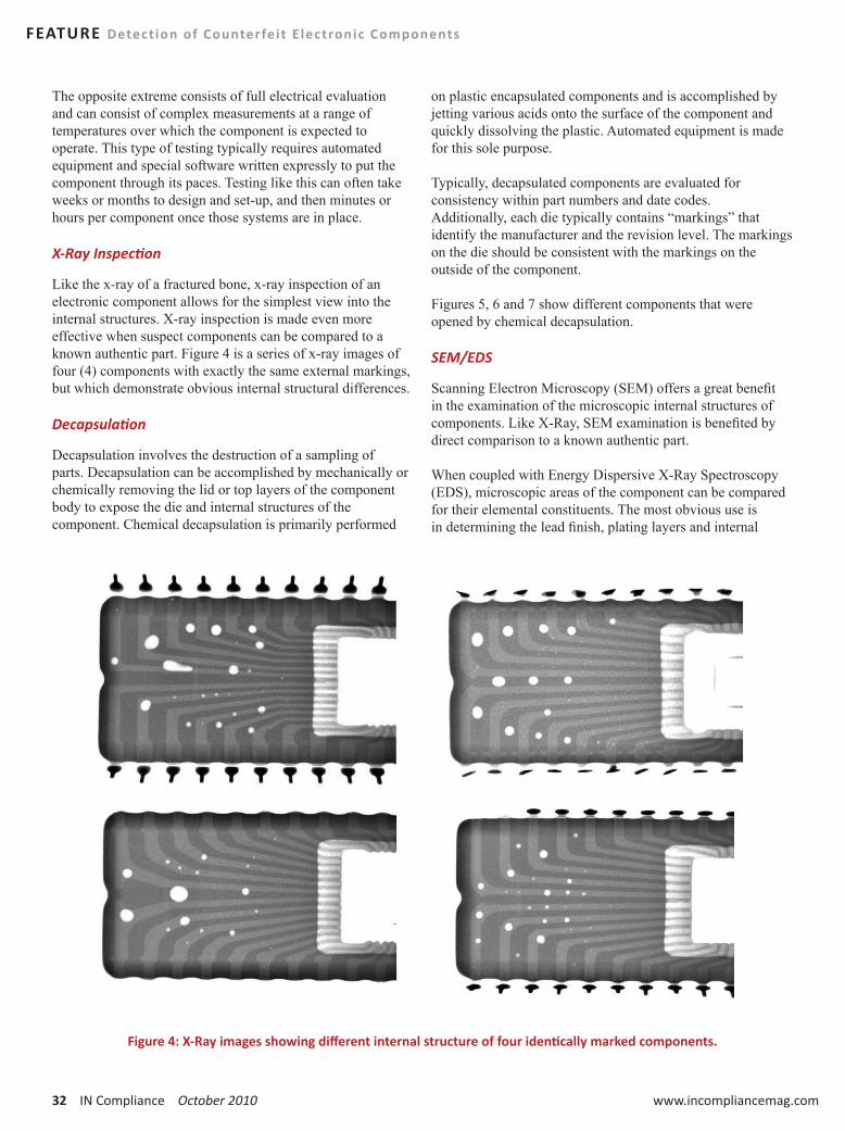
32 IN Compliance October 2010 www.incompliancemag.com
FEATURE Detect ion of Counterfeit E lectronic Components
The opposite extreme consists of full electrical evaluation and can consist of complex measurements at a range of temperatures over which the component is expected to operate. This type of testing typically requires automated equipment and special software written expressly to put the component through its paces. Testing like this can often take weeks or months to design and set-up, and then minutes or hours per component once those systems are in place.
X-Ray Inspection
Like the x-ray of a fractured bone, x-ray inspection of an electronic component allows for the simplest view into the internal structures. X-ray inspection is made even more effective when suspect components can be compared to a known authentic part. Figure 4 is a series of x-ray images of four (4) components with exactly the same external markings, but which demonstrate obvious internal structural differences.
Decapsulation
Decapsulation involves the destruction of a sampling of parts. Decapsulation can be accomplished by mechanically or chemically removing the lid or top layers of the component body to expose the die and internal structures of the component. Chemical decapsulation is primarily performed
on plastic encapsulated components and is accomplished by jetting various acids onto the surface of the component and quickly dissolving the plastic. Automated equipment is made for this sole purpose.
Typically, decapsulated components are evaluated for consistency within part numbers and date codes. Additionally, each die typically contains “markings” that identify the manufacturer and the revision level. The markings on the die should be consistent with the markings on the outside of the component.
Figures 5, 6 and 7 show different components that were opened by chemical decapsulation.
SEM/EDS
Scanning Electron Microscopy (SEM) offers a great benefit in the examination of the microscopic internal structures of components. Like X-Ray, SEM examination is benefited by direct comparison to a known authentic part.
When coupled with Energy Dispersive X-Ray Spectroscopy (EDS), microscopic areas of the component can be compared for their elemental constituents. The most obvious use is in determining the lead finish, plating layers and internal
Figure 4: X-Ray images showing different internal structure of four identically marked components.
October 2010 IN Compliance 33
Detect ion of Counterfeit E lectronic Components FEATURE
metallization. This technique can separate a tin-lead part from a RoHS compliant lead-free part or distinguish aluminum bond wires from gold. Both subtle differences, but each allows distinction of authentic from counterfeit parts.
XRF
X-Ray Fluorescence (XRF), like EDS, is used to identify elemental constituents. In general, the spot size of XRF measurement is much larger than that of EDS, making it not as useful at examining internal structures; however, it is much simpler to use than EDS and the equipment is much less expensive to purchase, making it a very convenient technique used to discriminate between leaded and lead-free parts.
Unconventional Detection Techniques
Counterfeiters continue to improve their craft; they too know the conventional techniques used to identify their product and they alter their processes so conventional detection techniques will not be effective. For this reason, unconventional detection techniques are being explored in order to stay ahead of the ever-resourceful counterfeiter.
Some of these techniques, such as FTIR, are newly being used in authenticity testing; others are old techniques being used in novel ways, such an x-ray machine calibrated specifically for counterfeit examination. It should be noted that virtually all of these techniques require a known good part for comparison purposes. These techniques focus on subtle differences between an authentic and unauthentic part and not on an obvious defect. Marking Permanency and Blacktopping
These tests are performed in a similar manner as the conventional techniques, but without the constraints of industry standard test methods, chemical solutions used for decades and static procedures. Some novel approaches include a variety of different chemical agents, extended exposure time (up to hours) and heated exposures. Chemicals which have been traditionally used in the decapsulation of components are now being used to attack the less resistant blacktopping.
When experimentation is being conducted to develop an appropriate procedure, it is even more imperative to test alongside a known good component to ensure the
new procedures can differentiate between authentic and counterfeit. Additionally, as deviation from standard methods occurs, close attention must be paid to determine if these techniques are too harsh and thus potentially more destructive to the part than older conventional methods. This will define whether the testing can be performed on 100% or just a sampling of the component lot or, simply put, determine if the part will be useable after the test.
SEM/EDS and XRF
SEM is becoming more commonly used as a technique to detect subtle differences of blacktopping. It is impossible for blacktopping to match the exact surface texture of the original component body; SEM offers examination at several 1000x magnification in order to reveal these textural differences. EDS is being used to detect minor elemental differences between the blacktopping and the actual component body. Additionally, by its very nature a part is handled more and goes through a variety of procedures during the counterfeiting process. Each of these increases the potential of contamination of the counterfeited part. SEM/EDS can detect and identify these elemental contaminants that would not be present on an authentic part.

34 IN Compliance October 2010 www.incompliancemag.com
FEATURE Detect ion of Counterfeit E lectronic Components
FTIR
Fourier Transform Infrared Spectroscopy (FTIR) is a method used to identify organic compounds. The polymers that comprise the component body and the blacktopping material used to hide the evidence of counterfeiting are all organic materials. With only a small sample of these materials, FTIR can distinguish between the appropriate polymer and the blacktopping polymer. FTIR can also detect organic contaminants on a counterfeited part much in the same way as SEM/EDS can detect elemental contaminants.
IC
Ion Chromatography (IC) is another technique that can be used to detect a third form of contamination – ionic. Ionic contamination is usually present in the form of salts or organic acids and may be deposited on a part by handling or application of chemicals during the counterfeiting process. IC can even determine something as simple as the type of water to which the part was exposed. A genuine component would only be exposed to deionized water while counterfeits are often rinsed with tap water. Looking for the telltale signs of tap water can quickly identify a counterfeit.
SAM
Scanning Acoustic Microscopy (SAM), a form of ultrasound, has been demonstrated to be an effective anti-counterfeiting screening tool. SAM uses cyclical sound waves to determine density differences within a sample.
SAM can be focused at different depths within the component to locate potential irregularities. When focused on the surface, SAM can show evidence of relabeling and, when compared to a known good component, it can show differences in surface texture indicative of blacktopping. When focused slightly subsurface, SAM can detect scratch marks under a layer of blacktopping. And, when focused inside the component, SAM can detect evidence of prior use and rework such as cracking, voiding and delamination.
Thermal Analysis
There are several thermal analysis techniques that can be employed on a small sampling of the component body. Thermal analysis measures some chemical or mechanical property as a function of temperature.
One technique, Differential Scanning Calorimetry (DSC) measures chemical reactions as a function of temperature. Reactions such as melt point, glass transition temperature, crystallinity and heat capacity are all properties inherent to specific polymers which DSC can measure. A small sample can be removed from a suspect component, tested
Figure 5: Overview of a decapsulated component displaying the die and bond wires which are now visible.
Figure 6: Close-Up of the die and bond wires within a component made visible by chemical decapsulation.
Figure 7: Close-Up of marking on the die visible after chemical decapsulation.
October 2010 IN Compliance 35
Detect ion of Counterfeit E lectronic Components FEATURE
and compared to known values of an authentic part. If a counterfeiter has altered the component body by adding a different polymer, DSC can detect this variation.
Another technique, Thermogravimetric Analysis (TGA), measures weight loss as a function of temperature. This method is useful in that different polymers decompose (lose weight) at different temperatures. Again, when comparing the component body of a suspect part to a known good part, if blacktopping is present or the component body has been altered, TGA can make these differences obvious.
Finally, Thermomechanical Analysis (TMA) measures dimensional change as a function of temperature. Two significant properties which can be examined are the softening point and coefficient of thermal expansion (CTE) of a polymer. Different polymers or even the same polymer with different amounts of fillers will produce different softening points and CTE’s.
All of these techniques can detect a potential counterfeit component from either a small scraping or a small cube of the component body. Additionally, all of the data can be compiled into a library so the properties of authentic components can be centralized and used for future comparisons.
SUMMARYIn conclusion, it has become evident that success in the battle against counterfeiting cannot be guaranteed by only employing a rigid series of tests. Specifying a list of several screening tests on a purchasing document will only allow the counterfeiter to determine how to evade detection. Efforts to detect and prevent counterfeiting of electronic components must show the same creativity and determination the counterfeiters show. There are a variety of anti-counterfeiting techniques that are in use, being developed and yet to be discovered. All will be needed to ensure only authentic components make their way into finished products. n
John Radman is currently the Senior Technical Director of Trace Laboratories. John has a BS in Physics from University of Maryland and has worked for Trace Labs since 1989. John heads a group of engineers and scientists that specialize in the areas of contamination and root cause failure
analysis. Our primary focus is on electronics and materials testing which includes new product development and material properties comparison. Recent work has focused on the electronics industry shift towards Pb-free alternatives. John is the author of many articles and technical presentation on topics, which include failure analysis, test techniques and RoHS compliance. John is the Chairman of the IPC Ion Chromatography/Ionic Conductivity Task Group and Vice Chair of IPC/UL 796F and 746F Task Group, treasury of the Rocky Mount Chapter of SMTA and an active member of ASTM, American National Standards Institute (ANSI), ASM International and Electronic Device Failure Analysis Society (EDFAS).
Dan Phillips is currently a Test Engineer at Trace Laboratories. Dan has a BS in Physics from McDaniel College and has worked for Trace Labs since 2006. Dan is a trained counterfeit components inspector; additionally, he specializes in product qualification and tin whisker testing, as well as contamination analysis.

36 IN Compliance October 2010 www.incompliancemag.com
Product liability has created problems for manufacturers and product sellers for many decades. These problems have been exacerbated by the expansion of product
liability laws throughout the world. In addition, there has been a proliferation of safety regulatory requirements, starting in the United States and then moving to the European Union. In addition, countries such as Japan, China, Australia, Canada, Brazil and South Africa have all recently established or strengthened their product safety regulatory regimes and requirements.
This all creates additional challenges for companies who want to and must comply with all laws, regulations and standards in any country where they sell their products. Such companies may also need to consider safety requirements in countries where they do not sell products to the extent they believe that these requirements establish a “state of the art” that they want to meet.
This article will discuss the basic kinds of defects that can be alleged in any product liability case. Next, I will discuss
as a Defense to Product Liability Litigationby Kenneth Ross
Compliance with Product Safety Standards

October 2010 IN Compliance 37
Compliance with Product Safety Standards FEATURE
the law as it pertains to compliance with standards. And finally, this article will discuss the EU directives applicable to electrical products and the effect of those directives on products sold in the EU and the United States.
U.S. THEORIES OF LIABILITY
Manufacturing Defects
A manufacturing defect exists if the product “departs from its intended design even though all possible care was exercised in the preparation and marketing of the product.” In other words, even if the manufacturer’s quality control was the best in the world, the fact that the product departed from its intended design meant that it had a manufacturing defect. The plaintiff need not prove that the manufacturer was negligent, just that the product was defective. The focus is on the product, not on the conduct of the manufacturer.
Common examples of manufacturing defects are products that are physically flawed, damaged, incorrectly assembled or do not comply with the manufacturer’s design specifications. The product turned out differently from that intended by the manufacturer. If that difference caused injury, the manufacturer will be liable. There are very few defenses.
Design Defects
A product is defective in design if a foreseeable risk of harm posed by the product “could have been reduced or avoided by the adoption of a reasonable alternative design” and the failure to use this alternative design makes the product not reasonably safe.
An alternative definition used by some courts is that a product is defective in design if it is dangerous to an extent beyond that which would be contemplated by the ordinary consumer.
These tests are much more subjective than the test for manufacturing defects and this subjectivity is the cause of most of the problems in product liability today. Manufacturers cannot easily determine how safe is safe enough and cannot predict how a jury will judge their products based on these tests. It is up to the jury to decide whether the manufacturer was reasonable or should have made a safer product.
Warnings and Instructions
The third main kind of defect involves inadequacies in warnings and instructions. The definition is similar to that of design defects and says that there is a defect if foreseeable

38 IN Compliance October 2010 www.incompliancemag.com
FEATURE Compliance with Product Safety Standards
risks of harm posed by the product “could have been reduced or avoided by …reasonable instructions or warnings” and this omission makes the product not reasonably safe.
Again this is an extremely subjective test that uses negligence principles as a basis for the jury to decide. This makes it difficult for a manufacturer to know how far to go to warn and instruct about safety hazards that remain in the product.
Post-sale Duty to Warn
One other theory of liability that is very important in a product liability case is post-sale duty to warn. A manufacturer may have a duty, after sale, to warn customers about hazards the manufacturer learns about after sale. This duty can arise even if the product was not defective or hazardous when sold. This duty is clearly based on negligence and involves any of the three kinds of defects described above.
LAW OF DESIGN DEFECTSThere are two kinds of design defect cases: those involving “inadvertent design errors” and another involving “conscious design choices.” Design errors are like manufacturing flaws and are treated easily by the courts. The design was wrong because someone made a mistake. The mistake created a hazard and someone was hurt. In that case, there is virtually no defense and the manufacturer would usually settle the case.
The more important type of design defect case involves conscious design choices. In these cases, the design turned out as intended by the designer and manufacturer. It had the level of safety expected by the designer for the intended use. However, the product still hurt someone who claims that the product should have been made safer. The plaintiff argues that an alternative safer design should have been used and the court must decide whether this alternative was preferable.
The development of the law in this area has caused confusion. There are several tests that have been developed for helping courts and juries decide whether there was a defective design.
Test for Design Defect
The predominant test in the United States for determining whether a product was “reasonably safe” involves, as mentioned above, whether there was a reasonable alternative design available. In many states, to answer this question, the jury is instructed to consider the following factors:
y Usefulness and desirability of the product.
y Safety of the product – the likelihood that it will cause injury and the probable seriousness of the injury.
y The availability of a substitute product that performed the same function and was safer.
y Ability of the manufacturer to eliminate the unsafe characteristic of the product without lessening its usefulness or making it too expensive.
y User’s ability to avoid harm by being careful when using the product.
y User’s awareness of the risk, either because it is obvious or because of suitable warnings and instructions.
y Feasibility by the manufacturer to spread the risk by way of price increases or purchasing insurance.
These factors provide a more comprehensive and understandable basis for a jury to make a decision. They also provide more guidance to the litigants to evaluate their case. Also, as importantly, they provide a basis by which a manufacturer could evaluate the safety of its product before sale and decide what is “reasonably safe.”
COMPLIANCE WITH STANDARDSAnother complex area involves laws, standards and regulations. As part of the initial analysis, a manufacturer must identify those that apply to its product. Sometimes, that is not easy to determine or there are numerous and different ones that must be reconciled, especially if the product is sold internationally.
Official laws and regulations, such as those passed by a state or national legislature, that apply to the product’s design must be complied with. If the product does not comply and this noncompliance caused the injury, then the manufacturer can be liable. Unfortunately, on the flip side, compliance with all applicable laws and regulations is not, for most products, an absolute defense in a product liability case. Therefore, a jury could come back and say a manufacturer should have exceeded laws and regulations pertaining to safety.
Similarly, industry standards and even certifications like UL are considered minimum. As a result, compliance with standards and certifications is not an absolute defense although it is pretty good evidence that the product was reasonably safe. Therefore, as with laws and regulations, the plaintiff can argue that you should have exceeded the standards. However, noncompliance is a problem if it caused or contributed to the injury. The reason is that the standard establishes a reasonable alternative design and the manufacturer has to justify why it didn’t comply.
So where does this lead the manufacturer? You should meet or exceed all applicable laws, regulations and mandatory or voluntary consensus standards in the countries where you sell products. If you don’t or can’t, then document the reason and make a reasonable judgment as to why your product is still reasonably safe.

October 2010 IN Compliance 39
Compliance with Product Safety Standards FEATURE
This is easier said than done. First, given the plethora of U.S. and international laws, regulations and standards, it is no easy task just to identify those that could apply to your product. Then, you need to figure out which ones take precedence over others where there is overlap.
In the European Union, there are ISO standards, EN/ISO standards and then Directives. Directives are similar to laws and EN/ISO standards have more authority than ISO and ANSI standards. So some are more important to comply with. But the bigger problem is figuring out which ones apply as there can be substantial overlap. Some U.S. and EU laws, regulations and standards are general and apply to a wide range of products. Some are much narrower. Generally, you want to first look to the narrower product specific document and then look to the more general requirements. The problem is figuring out where the “gaps” are in the narrower document that are then filled by the more general document. This is difficult to do and manufacturers need to also consider interpretations and guidances concerning directives and standards that are sometimes issued by government agencies, the EU and industry groups.
EU DIRECTIVES In the United States, there are various industry standards, some of which are voluntary and some of which are mandatory in that some federal, state or local agency adopted the standard and made it the law.
In the European Union, they developed a variety of directives that pertain to health and safety. A manufacturer must meet the requirements of applicable directives and obtain a CE mark to sell their products in Europe. These directives must be enacted by each member country of the EU during a given period of time. However, each country can try to modify the directive to meet their own needs and desires. Some directives allow such leeway, others don’t.
One problem with these directives, some of which are described below, is that they may become worldwide safety requirements and raise the “state of the art” beyond what is required in the U.S. Therefore, if a manufacturer sells a “safer” product in Europe that complies with the EU Directives and a “less safe” product in the U.S. that complies with, let’s say, ANSI standards, this could be a problem. Obviously, the safer product constitutes a “reasonable alternative design” and can be used by the plaintiffs to support a case of defective design.
So, you need to be especially careful when you have a safer product sold in Europe or elsewhere. While U.S. law allows different levels of safety in a product (i.e. automobiles), you may need to justify the reasonable safety of your less safe product to a government agency or jury sometime in the future.
I want to describe some of the Directives that generally apply to electrical products.
General Product Safety Directive (“GPSD”)
GPSD, Directive 2001/95/EC, was adopted in December 2001 for implementation no later than January 15, 2004. This directive establishes general safety requirements of many products, even those that would not be considered consumer products. This directive provides that manufacturers must sell safe products, defined as follows:
“safe product” shall mean any product which, under normal or reasonably foreseeable conditions of use including duration and, where applicable, putting into service, installation and maintenance requirements, does not present any risk or only the minimum risks compatible with the product’s use, considered to be acceptable and consistent with a high level of protection for the safety and health of persons,
There is also a reporting requirement for products that do not meet the above safety requirement. It says:
Where producers and distributors know or ought to know, on the basis of the information in their possession and as professionals, that a product that they have placed on the market poses risks to the consumer that are incompatible with the general safety requirement, they shall immediately inform the competent authorities of the Member States thereof…
There are also EU documents issued after 2004 which discuss the relationship of GPSD to products that fall under other directives, such as some of those discussed below.
The EU is undertaking further implementation and revisions to GPSD so that it conforms to their so-called “New Legislative Framework” which contains measures that have the objective of removing the remaining obstacles to free circulation of products between EU Member States.
Low Voltage Directive (“LVD”)
The most recent edition of the EU’s Low Voltage Directive is dated December 12, 2006. It is designated “Directive 2006/95/EC” and includes a conformity assessment procedure that is applied to equipment before placing it on the market. Compliance with this directive should confirm that the equipment meets the EU’s Essential Health and Safety Requirements (EHSRs) which such equipment must meet. The intent is for this Directive to cover all health and safety risks, thus ensuring that the electrical equipment is safe for its intended use. The manufacturer, and not a third party, is allowed to perform the conformity assessment. This Directive will be modernized and is part of the so-called

40 IN Compliance October 2010 www.incompliancemag.com
FEATURE Compliance with Product Safety Standards
“New Legislative Framework” which will deal with market surveillance, conformity assessment and accreditation and the meaning of the CE mark.
Electromagnetic Compatibility (EMC)
This Directive was enacted in 2004 and designated Directive 2004/108/EC. The purpose of the directive is to keep the side effects of electromagnetic interference under reasonable control. There is a new guide to this Directive dated February 8, 2010
Machinery Directive
The original Machinery Directive was passed in 1998. It subsequently was replaced in 2006 by Directive 2006 42/EC. This new directive is also part of the “New Legal Framework” which promotes harmonization through a combination of mandatory requirements and voluntary harmonized standards. The EU just issued an extensive guide to the 2006 Directive, dated June 2010. There are significant electrical safety requirements in this directive. In addition, there may be portions of other directives that apply to machinery.
Medical Device Directives (“MDD”)
EU Directives related to medical devices were harmonized in the 1990s. There are three directives that form the main legal framework for such products: active implantable medical devices (Directive 90/385/EEC), medical devices (Directive 93/42/EEC) and in vitro diagnostic medical devices (Directive 98/79/EC). These directives have been supplemented by additional directives, such as Directive 2007/47/EC, and the EU is considering revisions to this legal framework which will strengthen requirements for safety and surveillance.
The original Machinery Directive excluded medical devices. The current 2006 version does not exclude them and the EU issued an interpretation in August of 2009 on the relationship between the Machinery Directive and the active implantable portion of the MDD, Directive 93/42/EEC.
CE MARKINGThe CE mark is supposed to indicate that the product to which this is attached conforms to all relevant safety, health, environmental and other requirements in harmonized EU legislation. And all products in certain categories where EU directives exist must have the CE label attached to be sold in the EU. This includes electrical products.
Depending on the applicable directive’s requirements, conformity assessment can be performed by the manufacturer or by a “notified conformity assessment body.” Improperly affixing the CE mark to a product has significant legal ramifications, including criminal sanctions.
As with U.S. standards, while meeting the EU’s requirements in these directives allows the manufacturer to attach the CE mark, these requirements are a minimum and an individual member state can impose additional safety requirements for products sold in their country. Unfortunately, this diminishes the usefulness of harmonized standards based on directives.
Also, the CE mark has no legal significance in the U.S. Compliance with EU Directives can be helpful in proving that the product sold in the U.S. was reasonably safe in the U.S., but there is no extra weight given to the fact that a European legislative body enacted these requirements. This is no different than the weight that is given to U.S. enacted laws and regulations.
CONCLUSION Product liability in the U.S. is based, in large part, on the plaintiff offering a safer design and arguing that the manufacturer should have sold this safer product. EU requirements are, in many respects, much more rigorous than U.S. requirements. They are more detailed and overlapping and difficult and costly to comply with. Manufacturers could decide to sell only the safest product in the U.S. and elsewhere, even if that safer product is not required by laws and standards.
The trouble is that competitors might sell products with different levels of safety that might put the manufacturer at a competitive disadvantage. This is a costly decision for any manufacturer. Selling a safer product in the EU than you sell in the U.S. can result in significant liability. Selling a safer product in the U.S. that is not required by laws or standards may reduce liability by being more defensible. Unfortunately, it could also result in reduced sales that exceed any savings in litigation.
This can be a tough choice for a manufacturer from a financial, commercial and ethical standpoint. But one that must be made. n
Kenneth Ross is a very experienced lawyer and consultant who advises U.S. and foreign manufacturers and product sellers on product safety, product liability prevention and legal and regulatory compliance. This includes advice on how to identify, evaluate and minimize the risk of liability, especially product and contractual liability. Prior to entering private practice, Ken was an in-house lawyer at Westinghouse Electric and Emerson Electric where he counseled on safety and prevention issues and managed litigation. Ken can be reached at [email protected]. More of Ken’s articles can be accessed at www.productliabilityprevention.com.

October 2010 IN Compliance 41
The Future of EMC Engineeringby Mark I. Montrose, Montrose Compliance Services, Inc.
As a contributing author to present a series of controversial articles with the intent of raising awareness and discussion, I present a topic that is controversial–whether we should perform simulation analysis on systems and circuits or forgo this aspect of engineering analysis and go straight to production using the skills of an experienced engineer and rules of thumb.
For those that believe computational analysis is a primary aspect of successful design engineering, allow me to play devil’s advocate and say experience is better than simulation.As a manager, if you had to hire an engineer for a specialized task, would you prefer a senior level person with years of experience and whom has probably never performed a simulation in their life, but understands Maxwell’s Equations and physics, or a junior engineer who knows how to use simulation tools with minimal hands-on experience in design engineering but understands computational analysis?
There are those who believe that if you do not perform simulations on a printed circuit board design (PCB), i.e., SPICE or FDTD, you are not doing the job of being a competent electrical engineer. Rules of thumb are obsolete in their opinion and should never be used. What about the thousands of companies worldwide that have never simulated anything, nor ever will because they do not have expertise or the money to purchase software, but produce incredibly fantastic products? My question to these people–what are you going to simulate, only a schematic prior to layout, or full-blown post layout, which rarely occurs in many companies after the layout is completed? One must use rules of thumb to create a first-pass PCB layout based on mechanical, electrical or other reasons before simulation can occur. Rules of thumb get us near the finish line; however,
for high-technology products, one must simulate to ensure functionality. How many hours will overworked engineers in a small company be given, who need to get product out the door quickly, to perform a post-mortem simulation versus an experienced engineer that says “Do it this way because it will work based on sound engineering knowledge and years of experience.”
If a crisis condition occurs in a PCB after a prototype is built, who would we want to solve the problem, a simulation specialist after the fact or a senior engineer, especially if the non-compliant product generates EMI based on unknown parasitics. A senior engineer can quickly identify the problem area and usually incorporates a fix without the need for simulation.
Mark I. Montrose is an EMC consultant with Montrose Compliance Services, Inc. having 30 years of applied EMC experience. He currently sits on the Board of Directors of the IEEE (Division VI Director) and is a long term past member of the IEEE EMC Society Board of Directors as well as Champion and first President of the IEEE Product Safety Engineering Society. He provides professional consulting and training seminars worldwide and can be reached at [email protected]
Simulation versus Experience – Which is Better?

42 IN Compliance October 2010 www.incompliancemag.com
In Part 2, Principles of ESD Control, we introduced six principles of static control and six key elements of ESD program development and implementation. In Part 3,
we will cover some of the primary specific static control procedures and materials that will become part of your program. First, we review the principles.
BASIC PRINCIPLES OF STATIC CONTROLWe suggested focusing on just six basic principles in the development and implementation of effective ESD control programs:
y Design in protection by designing products and assemblies to be as robust as reasonable from the effects of ESD.
y Define the level of control needed in your environment.
y Identify and define the electrostatic protected areas (EPA), the areas in which you will be handling sensitive parts.
y Eliminate and reduce generation by reducing and eliminating static generating processes, keeping processes and materials at the same electrostatic potential and by providing appropriate ground paths to reduce charge generation and accumulation.
y Dissipate and neutralize by grounding, ionization and the use of conductive and dissipative static control materials.
y Protect products from ESD with proper grounding or shunting and the use of static control packaging and materials handling products.
At the facility level, our static control efforts concentrate on the last five principles. In this column we will concentrate on the primary materials and procedures that eliminate and reduce generation, dissipate and neutralize charges or protect sensitive products from ESD.
IDENTIFYING THE PROBLEM AREAS AND THE LEVEL OF CONTROLOne of the first questions we need to answer is “How sensitive are the parts and assemblies we are manufacturing or handling?” This information will guide you in determining the various procedures and materials required to control ESD in your environment.
How do you determine the sensitivity of your parts and assemblies or where can you get information about their ESD sensitivity? A first source would be the manufacturer or supplier of the component itself or the part data sheet. An additional source is System Reliability Center in Rome, NY, which publishes ESD susceptibility data for 22,000 devices, including microcircuits although this data is very generic and may not specifically cover the part you are actually using. It is
Fundamentals of Electrostatic DischargePart 3: Basic ESD Control Procedures and Materials
by the ESD Association

October 2010 IN Compliance 43
Fundamentals of E lectrostat ic Discharge FEATURE
also critical that you obtain both human-body model (HBM) and charge-device model (CDM) ratings. You may find that you need to have your specific parts tested for ESD sensitivity especially if the parts are known to operate at high speed or if the device performs a particularly critical function. We will discuss device sensitivity testing in Part 5 of this series.
The second question you need to answer is “Which areas of our facility need ESD protection?” This will allow you to define your specific electrostatic protected areas (EPAs), the areas in which you will be handling sensitive parts and the areas in which you will need to implement the control principles. Often you will find that there are more areas that require protection than you originally thought, usually wherever ESDS devices are handled. Typical areas requiring ESD protection are shown in Table 1.
GROUNDINGGrounding is especially important to effective ESD control and ESD grounding should be clearly defined and regularly evaluated.
The ESD ground provides a path to bring ESD protective materials and personnel to the same electrical potential. All conductors and dissipative materials in the environment, including personnel, must be bonded or electrically connected and attached to a known ground to create an equipotential balance between all items and personnel. Electrostatic protection can be maintained at a potential above a “zero” voltage ground reference as long as all items in the system are at the same potential. It is important to note that, by definition, insulators cannot lose their electrostatic charge by attachment to ground.
ESD Association Standard ANSI/ESD S6.1 – Grounding recommends a two-
step procedure for grounding ESD protective equipment.
The first step is to ground all components of the work area (worksurfaces, people, equipment, etc.) to the same electrical ground point called the “common point ground.” This common point ground is defined as a “system or method for connecting two or more grounding conductors to the same electrical potential.”
This ESD common point ground should be properly identified. ESD Association Standard ANSI/ESD S8.1 – Symbols, recommends the use of the symbol in Figure 1 to identify the common point ground.
The second step is to connect the common point ground to the equipment ground or the third wire (green) electrical ground connection. This is the preferred ground connection because all electrical equipment at the workstation is already
Receiving
Inspection
Stores and warehouses
Assembly
Test and inspection
Research and development
Packaging
Field service repair
Offices and laboratories
Clean rooms
Table 1: Typical Facility Areas Requiring ESD Protection
Figure 1: Common Point Ground Symbol

44 IN Compliance October 2010 www.incompliancemag.com
FEATURE Fundamentals of E lectrostat ic Discharge
connected to this ground. Connecting the ESD control materials or equipment to the equipment ground brings all components of the workstation to the same electrical potential. If a soldering iron used to repair an ESDS item was connected to the electrical ground and the surface containing the ESDS item was connected to an auxiliary ground, a difference in electrical potential could exist between the iron and the ESDS item. This difference in potential could cause damage to the item.
Any auxiliary grounds (water pipe, building frame, ground stake) present and used at the workstation must be bonded to the equipment ground to minimize differences in potential between the two grounds. Detailed information on ESD grounding can be found in ESD Association Standard ANSI/ESD S6.1 – Grounding.
CONTROLLING STATIC ON PERSONNEL AND MOVING EQUIPMENTPeople can be one of the prime generators of static electricity. The simple act of walking around or the motions required in repairing a board can generate several thousand volts on the human body. If not properly controlled, this static charge can easily discharge into a static sensitive device—a human body model (HBM) discharge. Also, a person can transfer charge to a board or other item making it vulnerable to charged-device model (CDM) events in a subsequent process.
Even in highly automated assembly and test processes, people still handle static sensitive devices…in the warehouse, in repair, in the lab, in transport. For this reason, static control programs place considerable emphasis on controlling personnel generated electrostatic discharge. Similarly, the movement of carts and other wheeled equipment through the facility also can generate static charges that can transfer to the products being transported on this equipment.
WRIST STRAPSTypically, wrist straps are the primary means of controlling static charge on personnel. When properly worn and connected to ground, a wrist strap keeps the person wearing it near ground potential. Because the person and other grounded objects in the work area are at or near the same potential, there can be no hazardous discharge between them. In addition, static charges are safely dissipated from the person to ground and do not accumulate.
Wrist straps have two major components, the cuff that goes around the person’s wrist and the ground cord that connects the cuff to the common point ground. Most wrist straps have a current limiting resistor molded into the ground cord head on the end that connects to the cuff. This resistor is most commonly one megohm, rated at least 1/4 watt with a working voltage rating of 250 volts.
Wrist straps have several failure mechanisms and therefore should be tested on a regular basis. Either daily testing at specific test stations or continuous monitoring at the workbench is recommended.
FLOORS, FLOOR MATS, FLOOR FINISHESA second method of controlling electrostatic charge on personnel is with the use of ESD protective floors in conjunction with ESD control footwear or foot straps. This combination of floor materials and footwear provides a ground path for the dissipation of electrostatic charge, thus reducing the charge accumulation on personnel and other objects to safe levels. In addition to dissipating charge, some floor materials (and floor finishes) also reduce triboelectric charging. The use of floor materials is especially appropriate in those areas where increased personnel mobility is necessary. In addition, floor materials can minimize charge accumulation on chairs, carts, lift trucks and other objects that move across the floor. However, those items require dissipative or conductive casters or wheels to make electrical contact with the floor. When used as the primary personnel grounding system, the resistance to ground including the person, footwear and floor must be the same as specified for wrist straps (< 35 x 10E6 ohms) or the accumulation in a standard walking voltage test (ANSI/ESD STM97.2) must be less than 100 volts.
SHOES, GROUNDERS, CASTERSUsed in combination with ESD protective floor materials, static control shoes, grounders, casters and wheels provide the necessary electrical contact between the person or object and the floor material. Insulative footwear, casters or wheels prevent static charges from flowing from the body to the floor to ground.
CLOTHINGClothing is a consideration in some ESD protective areas, especially in clean rooms and very dry environments. Clothing materials can generate electrostatic charges that may discharge into sensitive components or they may create electrostatic fields that may induce charges on the human body. Because clothing usually is electrically insulated or isolated from the body, charges on clothing fabrics are not necessarily dissipated to the skin and then to ground. Grounded static control garments are intended to minimize the effects of electrostatic fields or charges that may be present on a person’s clothing.
WORKSTATIONS AND WORKSURFACESAn ESD protective workstation refers to the work area of a single individual that is constructed and equipped with materials and equipment to limit damage to ESD sensitive items. It may be a stand-alone station in a stockroom,

October 2010 IN Compliance 45
Fundamentals of E lectrostat ic Discharge FEATURE
warehouse or assembly area or in a field location such as a computer bay in commercial aircraft. A workstation also may be located in a controlled area such as a clean room. The key ESD control elements comprising most workstations are a static dissipative worksurface, a means of grounding personnel (usually a wrist strap), a common grounding connection and appropriate signage and labeling. A typical workstation is shown in Figure 2.
The workstation provides a means for connecting all worksurfaces, fixtures, handling equipment and grounding devices to a common point ground. In addition, there may be provision for connecting additional personal grounding devices, equipment and accessories such as constant ground monitors and ionizers.
Static protective worksurfaces with a resistance to ground of 106 to 109 provide a surface that is at the same electrical potential as other ESD protective items in the workstation. They also provide an electrical path to ground for the controlled dissipation of any static potentials on materials that contact the surface. The worksurface also helps define a specific work area in which ESD sensitive devices may be safely handled. The worksurface is connected to the common point ground.
PRODUCTION EQUIPMENT AND PRODUCTION AIDSAlthough personnel generated static is usually the primary ESD culprit in many environments, automated manufacturing and test equipment also can pose an ESD problem. For example, a device may become charged from sliding down a feeder. If the device then contacts the insertion head or another conductive surface, a rapid discharge occurs from the device to the metal object—a Charged Device Model (CDM) event. In addition, various production aids such as hand tools, tapes or solvents can also be ESD concerns.
Grounding is the primary means of controlling static charge on equipment and many production aids. Much electrical equipment is required by the National Electrical Code to be connected to the equipment ground (the green wire) in order to carry fault currents. This ground connection also will function for ESD purposes. All electrical tools and equipment used to process ESD sensitive hardware require the 3 prong grounded type AC plug. Hand tools that are not electrically powered, i.e., pliers, wire cutters and tweezers, are usually grounded through the ESD worksurface and the (grounded) person using the conductive tools. Holding fixtures should be made of conductive or static dissipative materials when possible. Static dissipative materials are often suggested when very sensitive devices are being handled. A separate ground wire may be
required for conductive or dissipative fixtures not sitting on an ESD worksurface or handled by a grounded person. For those items that are composed of insulative materials, the use of ionization or application of topical antistats may be required to control generation and accumulation of static charges.
PACKAGING AND HANDLINGDirect protection of ESDS devices from electrostatic discharge is provided by packaging materials such as bags, corrugated boxes and rigid or semi-rigid plastic packages. The primary use of these items is to protect the product when it leaves the facility, usually when shipped to a customer. In addition, materials handling products such as tote boxes and other containers primarily provide protection during inter- or intra-facility transport.
The main ESD function of these packaging and materials handling products is to limit the possible impact of ESD from triboelectric charge generation, direct discharge and in some cases electrostatic fields. The initial consideration is to have low charging materials in contact with ESD sensitive items. For example, the low charging property would control triboelectric charge resulting from sliding a board or component into the package or container. A second requirement is that the material provides protection from direct electrostatic discharge. A third property that is sometimes specified is shielding from electrostatic fields. The selection of a suitable packaging material should consider all of these properties but in many cases not all are needed.
Many materials are available that provide all three properties: low charging, discharge protection and electric field suppression. The inside of these packaging materials have a low charging layer, but also have an outer layer with a surface resistance generally in the dissipative range. In many cases a low-charging, static dissipative package is adequate for handling within an EPA. Effectiveness, cost and device vulnerability to the various mechanisms need to be balanced
Figure 2: Typical ESD Workstation

46 IN Compliance October 2010 www.incompliancemag.com
FEATURE Fundamentals of E lectrostat ic Discharge
in making packaging decisions (see ANSI/ESD S541 for more detailed information).
Resistance or resistivity measurements help define the material’s ability to provide electrostatic shielding or charge dissipation. Electrostatic shielding attenuates electrostatic fields on the surface of a package in order to prevent a difference in electrical potential from existing inside the package. Electrostatic shielding is provided by materials that have a surface resistance equal to or less than 1.0 x 10³ when tested according to ANSI/ESD STM11.11 or a volume resistivity of equal to or less than 1.0 x 10 3 ohm-cm when tested according to the methods of ANSI/ESD STM 11.12. In addition, effective shielding may be provided by packaging materials that provide an air gap between the package and the product. Dissipative materials provide charge dissipation characteristics. These materials have a surface resistance greater than 1.0 x 10⁴ but less than or equal to 1.0 x 10¹¹ when tested according to ANSI/ESD STM11.11 or a volume resistivity greater than 1.0 x 10⁵ ohm-cm but less than or equal to 1.0 x 10¹² ohm-cm when tested according to the methods of ANSI/ESD STM11.12. The ability of some packages to provide discharge shielding may be evaluated using ANSI/ESD STM11.31 which measures the energy transferred to the package using an HBM discharge. A material’s low charging properties are not necessarily predicted by its resistance or resistivity.
IONIZATIONMost static control programs also deal with isolated conductors that cannot be grounded or insulating materials (e.g., most common plastics). Topical antistats may provide temporary ability to dissipate static charges under some circumstances.
More frequently, however, air ionization is used to neutralize the static charge on insulated and isolated objects by providing a balanced source of positive and negative ionized molecules of the gases of the surrounding air. Whatever static charge is present on objects in the work environment will be neutralized by attracting opposite polarity charges from the air. Because it uses only the air that is already present in the work environment, air ionization may be employed even in clean rooms where chemical sprays and some static dissipative materials are not usable.
Air ionization is one component of a complete static control program, not necessarily a substitute for grounding or other methods. Ionizers are used when it is not possible to properly ground everything and as backup to other static control methods. In clean rooms, air ionization may be one of the few methods of static control available.
CLEANROOMSWhile the basic methods of static control discussed here are applicable in most environments, cleanroom manufacturing processes require special considerations.
Many objects integral to the semiconductor manufacturing process (quartz, glass, plastic and ceramic) are inherently charge generating. Because these materials are insulators, this charge cannot be removed easily by grounding. Many static control materials contain carbon particles or surfactant additives that sometimes restrict their use in clean rooms. The need for personnel mobility and the use of clean room garments often make the use of wrist straps difficult. In these circumstances, ionization and flooring/footwear systems become key weapons against static charge.
IDENTIFICATIONA final element in our static control program is the use of appropriate symbols to identify static sensitive devices and assemblies, as well as products intended to control ESD. The two most widely accepted symbols for identifying ESDS parts or ESD control materials are defined in ESD Association Standard ANSI/ESD S8.1 — ESD Awareness Symbols.
The ESD Susceptibility Symbol (Figure 3) consists of a triangle, a reaching hand and a slash through the reaching hand. The triangle means “caution” and the slash through the reaching hand means “Don’t touch.” Because of its broad usage, the hand in the triangle has become associated with ESD and the symbol literally translates to “ESD sensitive stuff, don’t touch.”
The ESD Susceptibility Symbol is applied directly to integrated circuits, boards and assemblies that are static sensitive. It indicates that handling or use of this item may result in damage from ESD if proper precautions are not taken. If desired, the sensitivity level of the item may be added to the label.
The ESD Protective Symbol (Figure 4) consists of the reaching hand in the triangle.
Figure 3: ESD Susceptibility
Figure 4: ESD Protective Symbol

October 2010 IN Compliance 47
Fundamentals of E lectrostat ic Discharge FEATURE
An arc around the triangle replaces the slash. This “umbrella” means protection. The symbol indicates ESD protective material. It is applied to mats, chairs, wrist straps, garments, packaging and other items that provide ESD protection. It also may be used on equipment such as hand tools, conveyor belts or automated handlers that is especially designed or modified to provide ESD control.
Neither symbol is applied on ESD test equipment, footwear checkers, wrist strap testers, resistance or resistivity meters or similar items that are used for ESD purposes, but which do not provide actual protection.
SUMMARYEffective static control programs require a variety of procedures and materials. We have provided a brief overview of the most commonly used elements of a program. Additional in-depth discussion of individual materials and procedures can be found in publications such as the ESD Handbook (ESD TR20.20) published by the ESD Association.
Your program is up and running. How do you determine whether it is effective? How do you make sure your employees follow it? In Part 4, we will cover the topics of Auditing and Training. n
FOR ADDITIONAL INFORMATION
ESD Association Standards
y ANSI/ESD S1.1: Wrist Straps, ESD Association, Rome, NY
y ANSI/ESD STM2.1: Garments – Characterization, ESD Association, Rome, NY
y ANSI/ESD STM3.1: Ionization, ESD Association, Rome, NY
y ANSI/ESD SP3.3: Periodic Verification of Air Ionizers, ESD Association, Rome, NY
y ANSI/ESD S4.1: Worksurfaces – Resistance Measurements, ESD Association, Rome, NY
y ANSI/ESD STM4.2: ESD Protective Worksurfaces – Charge Dissipation Characteristics, ESD Association, Rome, NY
y ANSI/ESD S6.1: Grounding, ESD Association, Rome, NY
y ANSI/ESD S7.1: Resistive Characterization of Materials – Floor Materials, ESD Association, Rome, NY
y ANSI/ESD S8.1: Symbols – ESD Awareness, ESD Association, Rome, NY
y ANSI/ESD STM9.1: Footwear – Resistive Characterization, ESD Association, Rome, NY
y ESD SP9.2: Footwear – Foot Grounders Resistive Characterization, ESD Association, Rome, NY
y ANSI/ESD SP10.1: Automated Handling Equipment, ESD Association, Rome, NY
y ANSI/ESD STM11.11: Surface Resistance Measurement of Static Dissipative Planar Materials, ESD Association, Rome, NY
y ANSI/ESD STM11.12: Volume Resistance Measurement of Static Dissipative Planar Materials, ESD Association, Rome, NY
y ANSI/ESD STM11.13: Two – Point Resistance Measurement, ESD Association, Rome, NY
y ANSI/ESD STM11.31: Evaluating the Performance of Electrostatic Discharge Shielding Bags, ESD Association, Rome, NY
y ANSI/ESD STM12.1: Seating – Resistive Measurement, ESD Association, Rome, NY
y ESD STM13.1: Electrical Soldering/Desoldering Hand Tools, ESD Association, Rome, NY
y ANSI/ESD SP15.1: In-Use Resistance Testing of Gloves and Finger Cots, ESD Association, Rome, NY
y ANSI/ESD S20.20: Standard for the Development of an ESD Control Program, ESD Association, Rome, NY
y ANSI/ESD STM97.1: Floor Materials and Footwear – Resistance in Combination with a Person, ESD Association, Rome, NY
y ANSI/ESD STM97.2: Floor Materials and Footwear – Voltage Measurement in Combination with a Person, ESD Association, Rome, NY
y ANSI/ESD S541: Packaging Materials for ESD Sensitive Devices, ESD Association, Rome, NY
y ESD ADV1.0: Glossary of Terms, ESD Association, Rome, NY
y ESD ADV11.2: Triboelectric Charge Accumulation Testing, ESD Association, Rome, NY
y ESD ADV53.1: ESD Protective Workstations, ESD Association, Rome, NY
y ESD TR20.20: ESD Handbook, ESD Association, Rome, NY
y ESD TR53: Compliance Verification of ESD Protective Equipment and Materials, ESD Association, Rome, NY
OTHER RESOURCES y System Reliability Center, 201 Mill Street, Rome, NY
y ANSI/IEEE STD142, IEEE Green Book, Institute of Electrical and Electronics Engineers
y ANSI/NFPA 70, National Electrical Code, National Fire Protection Association, Quincy, MA

48 IN Compliance October 2010 www.incompliancemag.com
We all love planes, right? Well, most of us do and if you have that “bug” about aircraft and flying, then you’d enjoy a trip to the National Museum
of the United States Air Force in Dayton, Ohio. Recently, a regional meeting of the Antenna Measurement Techniques Association (AMTA) was held in Dayton. Before the regional meeting, Dr. Brian Kent, Chief Scientist for Low Observables and Electromagnetics, Sensors Directorate, of the Air Force Research Lab at Wright Patterson Air Force Base, and a past president of AMTA, lead a private tour of his “Top Ten” exhibits at the Museum. The jaw dropping tour was quick, but the comments and memories invoked by Dr. Kent were long lasting. Below is a summary of the “Top Ten” exhibits we visited. Also included is a short article on the famous “Doolittle Raid” contributed by one of the tour attendees, who happens to be a Board member of the AMTA organization. Please note that Dr. Kent based his comments on a compilation of facts and ideas from his own reading, research, as well as on details provided on the National Museum of the United States Air Force website (www.nationalmuseum.af.mil).
#1 TOUR STOPWe saw the Wright Brothers 1909 Military Flyer shown below. This aircraft on display is an exacting reproduction of the first aircraft purchased by the US Signal Corps, US Army for $30,000 in 1909 (which was a LOT of money back then). The Wright Brothers were quite active in the Dayton, Ohio area. Did you know there is an “Engineers Club” in Dayton of which the Wright Brothers were amongst the early members? It is a prestigious club for engineers that is still open today.
by Dr. Brian Kent, Air Force Research Laboratory, Wright-Patterson Air Force Base, Ohiowith contributions from Janet O’Neil, ETS-Lindgren
Speed Dating 22 Airplanes from the Propeller Era
AMTA Engineer Leads Techies on a Quick Historical Journey through the “Early Years” and “Air Power”
Galleries of the National Museum of the United States Air Force

October 2010 IN Compliance 49
Speed Dating 22 Airplanes from the Propel ler Era FEATURE
#2 TOUR STOPCheck out this French SPAD VII circa 1916 which was flown by the French, British, and Americans flying with “Lafayette Escadrille”. Pilots liked this plane because it could survive diving - without disintegrating - and was tough. Note the synchronized machine gun; earlier WWI models simply used metal plates to deflect bullets if the prop got in the way. This plane has impressive statistics: 180 horse power, top speed of 127 MPH, one .303 machine gun, 17,500 altitudes, and NO parachute!
#3 TOUR STOPWe paused to see the US Curtiss JN-4 “Jenny” trainer built in 1915. This was the first mass produced US aircraft, but it was not intended for combat due to its top speed of 87 MPH, 11,000 ft max altitude. It was considered “Obsolete” as a fighter plane by then with its 90 horse power engine.
#4 TOUR STOP This is a Fokker Dr. I – “Triplane”, one of the most successful German WW I fighters, and the favorite plane of Baron Von Richthofen, who got 19 of his last 21 kills (80 total) with
this aircraft. With a top speed of 103 miles per hour, it was highly maneuverable in a dogfight if handled properly. First appearing in 1917, it had a service ceiling of 19,600 ft with a 110 hp engine.
#5 TOUR STOPIf you think the cruise missile is a modern idea, think again! Charles Kettering (same as the city, same as General Motors, co-founder of the “Engineer’s Club” of Dayton, previously mentioned) tried to design and build the first ever remotely controlled bomb. Using a mini biplane whose wings were to fall off, several were built but none saw combat – but it was an innovation well ahead of its time. It had a range of 75 miles, and was intended to deliver 180 lbs of high explosives.
#6 TOUR STOPStrategic bombing was an idea which grew out of the early experiences of WWI. The Italian Caproni company built the first ever long range, multiengine aircraft primarily designed to drop bombs, and not to fight other aircraft. Caproni produced a new version, the Ca. 32 which was very similar

50 IN Compliance October 2010 www.incompliancemag.com
FEATURE Speed Dating 22 Airplanes from the Propel ler Era
to the Ca. 31, but it had three Isotta-Fraschini 100-hp water-cooled in-line engines. Three months after Italy’s entry into WWI, the first Ca. 32s attacked an Austrian air base at Aisovizza, and by the end of the year, regular raids were being mounted against other Austrian targets. It had a 372 mile range, sported three 150 HP engines, and two defensive machine guns, flying at 75 MPH. Loaded, it could climb to 14,765 ft.
#7 TOUR STOPWe saw the Boeing P-12E Pursuit (Fighter) developed during the interwar period, all on Boeing’s own dollar. Its fuselage was metallic, while the wings were still a hybrid of wood and fabric – but the march to all metal was on. The P-12E sported a 500 HP P&W radial engine, could ascend to 26,000 ft altitude, and cruised at 160 MPH. It had two .30 or one .30 and one .50 caliber machine guns. Wow!
#8 TOUR STOPMartin got into the action with its B-10 – the first all metal, mono-wing twin engine Bomber; Hap Arnold called it the air wonder of its day. It had many technical innovations – retractable landing gear, enclosed gun turrets, and carried 2,200 lbs of bombs! Hap Arnold flew a famous mission from Washington, DC to Alaska and back, an 8,290 round trip mile
journey in 1934! This aircraft was so fast, it outran every fighter of its day – giving the Army the (mistaken) impression that it could fly without fighter escorts. This “myth” of self defense in doctrine was to severely challenge the US Army Air Forces in WWII. The later models of the B-10 had 2,700 HP engines, could fly 183 MPH, and fly at 24,000 ft, with an amazing 1,300 mile range for its day.
#9 TOUR STOPNext we saw the Hawker Hurricane Mk IIa – One of the two main British fighters of the “Battle of Britain”. It was developed in 1935, yet was still a fabric covered aircraft. It composed over 70% of fighter command in the summer and fall of 1940. When the Battle of Britain commenced in July 1940, the Royal Air Force (RAF) Fighter Command had only 527 Hurricanes and 321 Spitfires to counter the enemy’s 2,700 aircraft. In spite of these overwhelming odds, the RAF was able to maintain air superiority over the skies of Great Britain. The Hurricanes absorbed the brunt of the German air attacks until a faster, more maneuverable Spitfire was available in quantity to blunt the successes of the German Messerschmitt Me 109. With a maximum speed of 340 mph and a ceiling of 35,000 ft, the 1,260 hp Rolls Royce engine powered the fighter which had eight offensive .303 caliber machine guns. As in WWI, American volunteers flew with the British before America entered the war. Their famous “Eagle Squadrons” first flew Hurricanes.

October 2010 IN Compliance 51
Speed Dating 22 Airplanes from the Propel ler Era FEATURE
#10 TOUR STOP - WWII GALLERYGet ready for a whirlwind tour. We could not name the top ten items on display so instead we named an entire gallery as being the Top 10! Below are just a few of the stand out planes in this stand out gallery!
Curtiss P-36A Hawk – America’s fighter plane was obsolete by Pearl Harbor. It was slower (313 MPH), lightly armed (two .30 cal. or one .30 and one .50 cal. machine guns) and flew lower than all of its competitors. Those not shot down in the opening days of the war became trainers or non-combat aircraft. Along with the P-40, the US Army Air Forces started the war with obsolescent aircraft. This plane was a dire beginning for a country so recently at war.
Lt Phillip Rasmussen on Dec 7th (pictured below) got off the ground – one of the few airplanes that did. He survived the war and dedicated this exhibit a few years ago.
Douglas B-18 Bolo – A standard USAAF bomber at the opening of WWII. It was purchased instead of Boeing’s Model 299 (B-17) because it was less costly, had half the engines, and was deemed “good enough” by the United States Army Air Forces (USAAF) brass working in a cost constrained environment. With two 1,000 HP engines, the Bolo could fly up to 23,000 ft with a payload of 4,500 lbs – but not very fast. In the Pacific, the Bolo was no match for the Zero. But the B-17, well, we’ll hear more about that later.
The Mitshubisi A6M2 Zero was the most famous symbol of Imperial Japan’s air power. With over 10,000 built, it outclassed nearly every fighter in late 1941, wherein armor and self defense were traded off for speed and rate of climb. It didn’t even have self sealing gas tanks, which was a significant omission that cost the lives of many experienced Japanese pilots early in the war. Capable of taking off from a carrier, it opened the war on December 7th by destroying most of the US Army and Navy aircraft while still parked on the ground.
The North American B-25B changed history on April 18, 1942. Less than six months after the Japanese raid on Pearl Harbor, the US struck the Japanese mainland with B-25Bs modified by Wright Field to take off from aircraft carriers. In 1943, this model cost $109,000 each! A total of 120 model B’s were built. In the end, they were mostly used for close air support and convoy interdiction in the pacific theater – the tyranny of distance never allowed the B-25 to strike Japan again. Please see the sidebar story for more information on the Doolittle Raid – a treasure of information in itself! We could also share the background now on the impact of the B-25B on the creation of Wright Patterson Air Force Base, but we’ll save that for another issue of this magazine!

52 IN Compliance October 2010 www.incompliancemag.com
FEATURE Speed Dating 22 Airplanes from the Propel ler Era
Next we viewed the Curtiss P-40E Warhawk, the premier US fighter fielded in any numbers when WWII opened. It was used in the Pacific, North Africa, and with the famous China “Flying Tiger” squadrons. Though it could not out climb a Zero, it could out dive one, and pilots learned to exploit the Zero’s weaknesses in defense. It would be replaced by P-47’s in Europe and P-38’s in the Pacific.
The Bell P-39: Think the idea of a cannon on an aircraft came with the A-10? Think again – the P-39 was a mid engine aircraft built around a 20 mm cannon! It was a bear to fly – its center of gravity changed through the flight envelope. However, though US pilots hated them, the Soviets loved them for tank busting and ground support; they took every P-39 we could give them in Lend Lease. Without a supercharger, the aircraft performed best under 17,000 ft – not good for a modern pursuit aircraft but fine for troop close air support.
Now on to the famous Boeing B-17G Flying Fortress which was a long range bomber in Europe and the Pacific Theater. Dubbed the “Model 299” by Boeing in 1935, the B-17 was the “loser” in the bomber competition in 1935, though the
USAAF bought 13 of them to “test and evaluate”. Because of their range and defensive firepower, production was expanded tremendously after the outbreak of WWII. The first 299 crashed during the competition – shortly after exceeding all performance goals – but lost the competition anyway. Six pre-war B-17’s flew non-stop from Miami to Argentina in the late 1930’s on a Good Will Tour. Modified extensively throughout the war with more defense and more powerful engines, the B-17G was the culmination. With a crew of 10, every aircraft loss cost 10 people their lives or the crew were held in captivity. The 1943 Schweinfurt raid over German Ball Bearing plants cost 60 bombers in a single day, thus shattering the myth of unescorted bombing raids. What they needed was an escort…
In stepped the first high altitude, high performance interceptor - the Lockheed P-38. Plagued with early developmental issues including a loss of control during dives, the P-38 was an outstanding fighter. It served early on in Europe and ultimately gave the B-17’s the escort they needed. The German’s called them the “Forked-tail devil”. While the bombers loved them, the pilots in Europe did not as they flew at 35,000 ft WITHOUT a heater, and frequently lost control in fast dives. Lockheed solved the problem, but the field repair kits to correct this were torpedoed in route to England, and the 8th AF never got the fixes! When the P-47 became available, the 8th Air Force unloaded their P-38’s to Africa and the Pacific, where they were stellar. No fighter plane, even the Zero, could outturn a P-38 under 10,000 ft. The most successful of American aces flew P-38’s, and a P-38 shot down Admiral Yamamoto, the architect of Pearl Harbor in 1943. Over 10,000 of these planes were built.

October 2010 IN Compliance 53
Speed Dating 22 Airplanes from the Propel ler Era FEATURE
As more fighters shared the role of air superiority and ground support, their needs created different airplanes. The P-47D “Jug” was extremely heavy, but powered by a massive engine. It had dense armor plating to protect the pilot, and could drop bombs and strafe – yet compete with Messerschmitt 109s and Focke-Wulf 190s over Europe. Many times P-47s came back with bullets in multiple cylinders, yet still were flying. Over 12,400 of these planes were built!
The Focke-Wulf 190 was Germany’s best piston engine fighter. Over 20,000 were built, and they played havoc with the B-17 flying from England and B-24’s flying from Africa. A formidable and nimble aircraft, it had a maximum speed of 425 MPH, and outturned even the maneuverable Spitfire!
The North American P-51D Mustang was America’s most famous fighter, with a 437 MPH top speed. This plane was upgraded through the Korean War with the last model achieving 487 MPH in level flight. In all, over 15,000 Mustangs were built. By mid 1944, it was the preferred long range fighter for bomber escort, and was well suited for that mission. After the war, the USAAF retired most P-47’s and
kept the sleeker (sexier) P-51 – what became a costly mistake in 1950. In ground support missions, the Mustangs liquid cooled engine could be defeated by a hole in the coolant line – leaving veteran USAF pilots pining for the rugged P-47.
Below we saw the Me-262 Schwalbe (Swallow). Capable of flying 540 MPH, it was the highest technically equipped aircraft of WWII fielded by the Germans and could have turned the tide of the air superiority in WWII. The Mustang had to be perfectly positioned to bring down a 262, though several did. The 262 deliveries arrived too late. Though 1,400 were produced, only 300 saw combat – the rest were relentlessly destroyed by the Allies who by this time had complete air superiority. The 262’s caused losses to bombers, but it was too little, too late.

54 IN Compliance October 2010 www.incompliancemag.com
FEATURE Speed Dating 22 Airplanes from the Propel ler Era
B-29 – BOCKSCAR THE BOMBER THAT ENDED WWIIThe tyranny of the Pacific theater’s size was finally met by the B-29 – the bomber was well-suited for the Pacific theater. With countless innovations and patentable ideas, the B-29 was fully pressurized, had computer controlled guns (that shot down MIGs in Korea), and a range of 3,700 miles with four engines of 2,200 HP each! While the aircraft had the range, bad Japanese weather thwarted the B-29 to the point that Curtis LeMay used it in a manner it was never designed for – low altitude fire bombing. B-29’s had the most destructive raids in the war over Japan – culminating with the dropping of both atomic weapons which ended WWII.
CONCLUSIONWe hope you enjoyed this trip down memory lane in aviation history, with an emphasis on the planes that were used during WWII. It’s tempting to be an “arm chair” historian and review these stories and ask “what if” – that is, what if the Germans hadn’t fought over production of the 262 plane? What if the USAF hadn’t been tempted by the “sexier” P-51? What if the weather had been better in the Pacific Theater in July of 1945? It’s all history now, but the truth makes a good story. n
COMING UPSo what about the AMTA regional meeting you ask? That’s why we were in Dayton, after all. The day following this museum tour, AMTA and IEEE members in the Dayton area gathered for a seminar on advances in antenna measurement techniques. In the next issue of this magazine, we will share some of the interesting advances in antenna measurement techniques that this organization addresses, primarily for the RF microwave community. Look for an article by AMTA Board member and IEEE EMC Society member, Dr. Vince Rodriguez of ETS-Lindgren, on the history and development of the classic horn antenna over the years. You’ll find this versatile antenna used for RF microwave, wireless, automotive and EMC applications. Imagine if this antenna as we know it today had been available during WWII – now that’s another story!
ABOUT THE NATIONAL MUSEUM OF THE UNITED STATES AIR FORCEThe National Museum of the United States Air Force located at Wright-Patterson Air Force Base near Dayton, Ohio, is the service’s national institution for preserving and presenting the Air Force story. Each year more than one million visitors come to the museum to learn about the mission, history and evolving capabilities of America’s Air Force. The museum is the world’s largest and oldest military aviation museum featuring more than 400 aerospace vehicles amid more than 17 acres of indoor exhibit space. Thousands of personal artifacts, photographs and documents further highlight the people and events that comprise the Air Force storyline, from the beginnings of military flight to today’s war on terrorism. Visit www.nationalmuseum.af.mil for more information.
Brian Kent, a member of the scientific and professional cadre of senior executives, is Chief Scientist for Low Observables and Electromagnetics, Sensors Directorate, Air Force Research Laboratory, Wright-Patterson Air Force Base, Ohio. He performs and directs research and development activities at the Multi-Spectral Measurement Facility, a national Center of Excellence within the Sensors Directorate. His primary responsibilities include the development and transition of advanced low observable electromagnetic analysis and measurement techniques to the Department of Defense and their aerospace industrial partners. His research encompasses extremely broadband electromagnetic test and evaluation techniques, with special emphasis on the acquisition of measured performance data from basic 6.1/6.2 technology components through fully fielded and sustained weapon systems. In addition to his electromagnetic measurement activities, he collaborates on numerous interdisciplinary research problems that encompass multiple AFRL directorates, customers from other DOD components, as well as the manned space program managed by NASA. Dr. Kent joined the Air Force Avionics Laboratory in 1976 as cooperative engineering student through Michigan State University. He began his career performing research in avionics, digital flight displays and radar signature measurements. Through a career broadening engineering assignment with the Directorate of Engineering, Aeronautical Systems Division, he modeled a number of foreign threat missile systems and performed offensive and defensive electronic combat systems assessments. He received a National Science Foundation Fellowship in 1979, working at both the Air Force Wright Aeronautical Laboratories and the Ohio State University Electroscience Laboratory until the completion of his doctorate. Dr. Kent spent two years in the Passive Observables Branch of the Avionics Laboratory, later transferring to the AFWAL Signature Technology Office. From 1985 to 1992, Dr. Kent was involved with classified research efforts, managed through the Air Force Wright Laboratory, now the AFRL. During his tenure with AFRL and its predecessor organizations, Dr. Kent held a variety of positions. He has made pioneering and lasting contributions to the areas of signature measurement technology, and successfully established international standards for performing radar signature testing. Dr. Kent has authored and co-authored more than 80 archival articles and technical
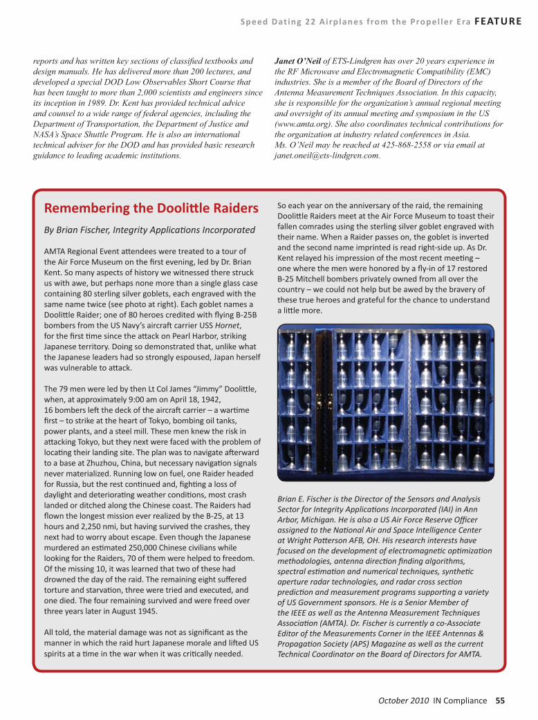
October 2010 IN Compliance 55
reports and has written key sections of classified textbooks and design manuals. He has delivered more than 200 lectures, and developed a special DOD Low Observables Short Course that has been taught to more than 2,000 scientists and engineers since its inception in 1989. Dr. Kent has provided technical advice and counsel to a wide range of federal agencies, including the Department of Transportation, the Department of Justice and NASA’s Space Shuttle Program. He is also an international technical adviser for the DOD and has provided basic research guidance to leading academic institutions.
Janet O’Neil of ETS-Lindgren has over 20 years experience in the RF Microwave and Electromagnetic Compatibility (EMC) industries. She is a member of the Board of Directors of the Antenna Measurement Techniques Association. In this capacity, she is responsible for the organization’s annual regional meeting and oversight of its annual meeting and symposium in the US (www.amta.org). She also coordinates technical contributions for the organization at industry related conferences in Asia. Ms. O’Neil may be reached at 425-868-2558 or via email at [email protected].
Speed Dating 22 Airplanes from the Propel ler Era FEATURE
Remembering the Doolittle RaidersBy Brian Fischer, Integrity Applications Incorporated
AMTA Regional Event attendees were treated to a tour of the Air Force Museum on the first evening, led by Dr. Brian Kent. So many aspects of history we witnessed there struck us with awe, but perhaps none more than a single glass case containing 80 sterling silver goblets, each engraved with the same name twice (see photo at right). Each goblet names a Doolittle Raider; one of 80 heroes credited with flying B-25B bombers from the US Navy’s aircraft carrier USS Hornet, for the first time since the attack on Pearl Harbor, striking Japanese territory. Doing so demonstrated that, unlike what the Japanese leaders had so strongly espoused, Japan herself was vulnerable to attack.
The 79 men were led by then Lt Col James “Jimmy” Doolittle, when, at approximately 9:00 am on April 18, 1942, 16 bombers left the deck of the aircraft carrier – a wartime first – to strike at the heart of Tokyo, bombing oil tanks, power plants, and a steel mill. These men knew the risk in attacking Tokyo, but they next were faced with the problem of locating their landing site. The plan was to navigate afterward to a base at Zhuzhou, China, but necessary navigation signals never materialized. Running low on fuel, one Raider headed for Russia, but the rest continued and, fighting a loss of daylight and deteriorating weather conditions, most crash landed or ditched along the Chinese coast. The Raiders had flown the longest mission ever realized by the B-25, at 13 hours and 2,250 nmi, but having survived the crashes, they next had to worry about escape. Even though the Japanese murdered an estimated 250,000 Chinese civilians while looking for the Raiders, 70 of them were helped to freedom. Of the missing 10, it was learned that two of these had drowned the day of the raid. The remaining eight suffered torture and starvation, three were tried and executed, and one died. The four remaining survived and were freed over three years later in August 1945.
All told, the material damage was not as significant as the manner in which the raid hurt Japanese morale and lifted US spirits at a time in the war when it was critically needed.
So each year on the anniversary of the raid, the remaining Doolittle Raiders meet at the Air Force Museum to toast their fallen comrades using the sterling silver goblet engraved with their name. When a Raider passes on, the goblet is inverted and the second name imprinted is read right-side up. As Dr. Kent relayed his impression of the most recent meeting – one where the men were honored by a fly-in of 17 restored B-25 Mitchell bombers privately owned from all over the country – we could not help but be awed by the bravery of these true heroes and grateful for the chance to understand a little more.
Brian E. Fischer is the Director of the Sensors and Analysis Sector for Integrity Applications Incorporated (IAI) in Ann Arbor, Michigan. He is also a US Air Force Reserve Officer assigned to the National Air and Space Intelligence Center at Wright Patterson AFB, OH. His research interests have focused on the development of electromagnetic optimization methodologies, antenna direction finding algorithms, spectral estimation and numerical techniques, synthetic aperture radar technologies, and radar cross section prediction and measurement programs supporting a variety of US Government sponsors. He is a Senior Member of the IEEE as well as the Antenna Measurement Techniques Association (AMTA). Dr. Fischer is currently a co-Associate Editor of the Measurements Corner in the IEEE Antennas & Propagation Society (APS) Magazine as well as the current Technical Coordinator on the Board of Directors for AMTA.

Advance registration extended through October 1!

October 2010 IN Compliance 57
2010 SYMPOSIUM ON PRODUCT COMPLIANCE ENGINEERING
KeynoteCheck, Double Check, and Don’t Forget the ObviousDean Woodard, Director, Defect Investigations, Office of Compliance - U.S. Consumer Product Safety Commission
Dean W. Woodard is the Director of the Defect Investigations Division of the U.S. Consumer Product Safety Commission. He has led this division for the past two years. His previous governmental experience was leading the Aerospace Industries Division of the U.S. Department of Commerce for five years. Prior to his experience in government Mr. Woodard served as Chief Engineer for Hexcel Corporation’s Graham, Texas plant and also later served as a plant manager for Baxter Travenol’s cardiovascular division, Vanguard Plastics, and DRG Medical Packaging. Dean was project director and opened Coca-Cola’s first bottling plant in Russia. Mr.Woodard holds Bachelor and Master degrees from the University of Oklahoma and is ABD from North Texas. He has traveled Kazakhstan extensively by horseback.
Featured TalkAutomobile Sudden Acceleration: Controlling the Safety Risks caused by EMIKeith Armstrong, Cherry Clough Consultants
Abstract: Sudden Unintended Acceleration (SUA) has been a problem for all automakers ever since the early 1980s, but automakers and the US Government’s National Highway Transportation Agency (NHTSA) have always blamed it on driver “pedal error”. This presentation compares the claims for electronic safety made by both NHTSA and automakers with what we as designers and assessors of safety-related systems would consider necessary whenever electronic malfunctions, software glitches or EMI could increase functional safety risks. It will include the reasons why we cannot rely upon motor vehicle event data recordings (so-called ‘black boxes’), why EMC testing cannot prove safe design, and include recent test data showing that EMI can cause a car engine to race, without triggering any fault codes.
Keith graduated from Imperial College, London, in 1972 with an Honours Degree in Electrical Engineering, majoring in Circuit Design, Control Theory and Electromagnetic Field Theory. He has been a member of the IEE/IET since 1977 and a member of the IEEE since 1997, a UK Chartered Engineer since 1978, a Group 1 European Engineer since 1988. He was appointed as a Fellow of the IET and as a Senior Member of the IEEE in 2010.
After working as an electronic designer, then as project manager and design department manager, Keith started Cherry Clough Consultants in 1990 to help companies reduce financial risks and project timescales through the use of proven good EMC engineering practices.
Over the last 20 years, Keith has presented many papers, demonstrations, and training courses on good EMC engineering techniques and on EMC for Functional Safety, worldwide, and also written very many articles on these topics.
He chairs the IET’s Working Group on “EMC and Functional Safety”, and is the UK Government’s appointed expert to the IEC committees working on 61000-1-2 (EMC & Functional Safety), 60601-1-2 (EMC for Medical Devices), and 61000-6-7 (Generic standard on EMC & Functional Safety).

58 IN Compliance October 2010 www.incompliancemag.com
PROGRAM
Monday, October 187:00 AM - 8:00 AM - SPEAKER BREAKFAST
8:15 AM - 8:30 AM - WELCOME MESSAGEIEEE PSES Symposium WelcomeSteve Brody
8:30 AM - 9:30 AM - KEYNOTE“Check, Double Check, and Don’t Forget the Obvious” Dean Woodard
9:30 AM - 10:30 AM - SESSIONS
Monday: Session 1 - 1Product Recall Preparedness and ImplementationKenneth Ross (Bowman and Brooke LLP, USA)
Monday: Session 1 - 2Overview of Regulatory LabelingGary Schrempp (Dell Inc, USA)
Monday: Session 1 - 3Class 2 Transformers and Plastic Enclosed Printed Circuit Boards: A Potentially Perilous CombinationDaniel Churchward (Kodiak Enterprises, USA)
10:30 AM - 11:00 AM - BREAK
11:00 AM - 12:00 PM - SESSIONS
Monday: Session 2 - 1Overview of Regulatory Labeling Gary Schrempp
Monday: Session 2 - 2Supporting Qualification - Safety Standard Compliant Process Planning and MonitoringHenning Jost (University of Oldenburg, Germany); Silke Köhler (German Aerospace Center (DLR), Germany); Stefan Häusler (OFFIS, Germany); Jan Gacnik (German Aerospace Center (DLR), Germany); Axel Hahn (OFFIS, Germany); Frank Köster (German Aerospace Center (DLR), Germany); Karsten Lemmer (German Aerospace Center (DLR), Germany)
Monday: Session 2 – 3IEC62368-1 - A Twist on the Approach to Fire Safety of Low Power Circuits. Bob Griffin
12:00 PM - 1:30 PM - MONDAY LUNCH
1:30 PM - 2:30 PM - SESSIONS
Monday: Session 3- 1Electrical Evidence at Fire ScenesDavid Utt (Fire Forensics & Safety Consulting LLC, USA)
Monday: Session 3 - 2Regulatory Affairs - A Global UpdateMichael Loerzer (Globalnorm GmbH, Germany)
Monday: Session 3 - 3IEC62368-1 - A Twist on the Approach to Fire Safety of Low Power CircuitsBob Griffin (IBM Corporation, USA)
2:30 PM - 3:30 PM - SPECIAL GUEST SPEAKERAutomobile Sudden Acceleration: Controlling the Safety Risks caused by EMIKeith Armstrong (Cherry Clough Consultants, United Kingdom)
3:30 PM - 4:00 PM - BREAK
4:00 PM - 5:00 PM - PANEL DISCUSSIONWhat Can the Safety Community Learn from the Toyota Recall
Tuesday, October 197:15 AM - 8:15 AM - SPEAKER BREAKFAST
8:30 AM - 9:30 AM - SESSIONS
Tuesday: Session 1 - 1Protection of Outside Plant ConductorsDon Gies (Alcatel-Lucent, USA)
Tuesday: Session 1 - 2Applied Safety Science and Engineering Techniques (ASSET™): Taking HBSE to the Next LevelThomas Lanzisero (UL Inc, USA)
Tuesday: Session 1 - 3Product Safety 102 - Mechanical TestingBill Bisenius (ED&D, Inc., USA)
9:30 AM - 10:30 AM - SESSIONS
Tuesday: Session 2 - 1Introduction to Primary Side Power Supply FailuresJeremiah Stepan (Exponent, Inc., USA)
Tuesday: Session 2 - 2Electromagnetic Compatibility for Flywheel Energy Storage Systems In Rail-Transit Traction Power ApplicationsEdward Davis (Electromagnetic Compatibility Society, USA); Andrew Goodwin (Pentadyne, USA)
Tuesday: Session 2 - 3Product Safety 102 Hipot TestingDwayne Davis (Associated Research Inc., USA)
10:30 AM - 11:00 AM - BREAK

October 2010 IN Compliance 59
PROGRAM
11:00 AM - 12:00 PM - SESSIONS
Tuesday: Session 3 - 1Thermal Shutdown Characteristics of Polymer Insulating Materials Used in Lithium Ion BatteriesBala Pinnangudi (Exponent, USA); Snehal Dalal (Exponent, USA); Jan Swart (Exponent Inc., USA); Nosh Medora (IEEE, USA); Ashish Arora (Exponent, USA)
Tuesday: Session 3 - 2Conducting High Frequency Electrical Measurements - Case Study Using a TASER M18 DeviceNosh Medora (IEEE, USA)
Tuesday: Session 3 - 3Product Safety 102 - Creepage & Clearance MeasurementsBill Bisenius (ED&D, Inc., USA)
12:00 PM - 1:30 PM - TUESDAY LUNCH
1:30 PM - 2:30 PM - SESSIONS
Tuesday: Session 4 - 1Safety Interlock Systems Used in Electrical/Electronic EquipmentLal Bahra (Dell Inc., USA)
Tuesday: Session 4 - 2Safety Considerations for Smart Grid Technology EquipmentDon Gies (Alcatel-Lucent, USA)
Tuesday: Session 4 - 3Product Safety Touch Current DemoPeter Perkins (P.E. Perkins PE, USA); Robert Johnson (ITE Safety, USA)
2:30 PM - 3:30 PM - SESSIONS
Tuesday: Session 5 -1Protective Earthing and Protective Bonding Conductors Used as Safeguards in Electrical EquipmentLal Bahra (Dell Inc., USA)
Tuesday: Session 5 -2Safety Issues and Damage to Equipment with Both Smart Grid and Home Network ConnectionsAlbert R Martin (Tyco Electronics, USA)
Tuesday: Session 5 -3Accessible Hot Surfaces & Burn HazardsAshish Arora (Exponent, USA); Nosh Medora (IEEE, USA); Steven Murray (Exponent, USA)
3:30 PM - 4:00 PM – BREAK
4:00 PM - 5:00 PM - SESSIONS
Panel DiscussionA Product Safety Engineer’s Perspective - Working with Development Engineers
Panel DiscussionSmart Grid and New Technoloies - What it Means for Product Safety
Wednesday, October 207:15 AM - 8:15 AM - SPEAKER BREAKFAST
8:30 AM - 9:30 AM - SESSIONS
Wednesday: Session 1 - 1RoHS Recast - Are you ready?Krista Botsford (Botsford EcoTech Partners LLC, USA)
Wednesday: Session 1 - 2Automotive Paint Spray Booth Safety - How a Paint Booth Makes a Dangerous Operation Less oDale W. Soos (Testing and Certification, USA)
Wednesday: Session 1 - 3Introduction to RATC (Open to Guests)Doug Nix
9:30 AM - 10:30 AM - SESSIONS
Wednesday: Session 2 - 1Preparing Products for Environmental ComplianceKrista Botsford (Botsford EcoTech Partners LLC, USA)
Wednesday: Session 2 - 2Hazardous Locations and Solid-State Lighting Certification OverviewBrad Bombardier (Intertek, USA)
Wednesday: Session 2 - 3Introduction to RATC (Open to Guests)Doug Nix
10:30 AM - 11:00 AM - BREAK
11:00 AM - 12:00 PM - SESSIONS
Wednesday: Session 3 - 1Meeting the Restricted Substance Compliance ChallengeThomas Svoboda (Intertek, USA)
Wednesday: Session 3 - 2Audio Level Safety Limits and their Impact on Personal Music PlayersTed Eckert (Microsoft Corporation, USA)
Wednesday: Session 3 - 3Effects of High Frequency Voltage Stress on Air Insulation and Solid InsulationFlore Chiang (Underwriters Laboratories Taiwan Co., Ltd., Taiwan)

60 IN Compliance October 2010 www.incompliancemag.com
EXHIBITOR PROFILES
Advanced Test Equipment Rentalswww.atecorp.com
Advanced Test Equipment Rentals offers effective solutions on rentals, leases, and sales of leading-edge test and measurement equipment used throughout the product safety and environmental industries. Our wide selection includes a large inventory of equipment manufactured by premier brands such as Teseq, Agilent, QuadTech, Kikusui, Fluke, Narda, Bruel & Kjaer and more. We also carry a full line of EMC equipment for both compliance and pre-compliance testing.
ARC Technologieswww.arcserv.com
ARC Technologies is the leading supplier of microwave absorbing materials for commercial and defense applications. While providing a complete range of standard absorber products, ARC Technologies also offers dielectric materials, composites, radomes, and radar absorbing structures (RAS). Whether you are facing problems at 50 MHz or 100 GHz, nearfield or farfield, narrowband or broadband, ARC Technologies has a product or will develop an application specific product to meet your specifications.
Associated Researchwww.asresearch.com
Associated Research, an ISO 9001 registered company, has been the leader in the electrical safety compliance testing industry for over 70 years! Today, Associated Research offers a complete product line of electrical safety compliance testers. Included in their product offering are AC Hipot, DC Hipot, Insulation Resistance, Ground Bond, Functional Run, Line Leakage testers, and Multi-Function Electrical Safety Compliance Analyzers. Associated Research has made the commitment to have their entire standard line of instruments safety agency listed. They also hold more US patents than any other company in the industry.
They provide a wide range of technical and educational documents to help manufacturers perform their tests safely and efficiently. This includes online webinars and even private training. With a combined focus on product innovation and customer support Associated Research continues to lead the industry.
Curtis-Strauswww.bureauveritas.com/wps/wcm/connect/bv_com/Group
Curtis-Straus (a Bureau Veritas Company) is an approved NRTL as listed on the OSHA website and in Canada as listed on the SCC website. Its employees are skilled in handling all aspects of testing, report writing, final reports, certification, initial plant inspections and follow-up service. This allows us to provide rapid turnaround, resulting in a shorter time to market and ultimately less expense. We can provide you with the added convenience of arranging a transfer of existing Certifications. For years, Curtis-Straus has assisted customers in mitigating safety, EMC and Environmental non-compliance issues.
CASE Forensicswww.case4n6.com
CASE Forensics has provided consulting engineering services since 1990. Our experience investigating field failures provides an intrinsic knowledge base to assist you with research, development and product safety testing.
Compliance Worldwide, Inc.www.cw-inc.com
Compliance Worldwide is an independent testing laboratory A2LA Accredited under ISO Guide 17025-2005 that provides EMC, EMI/RFI, CE Mark, Wireless and Wireline Telecommunications Testing and Federal Communications Commission (FCC)/Industry Canada (IC) approval liaison services for manufacturers of Electronic Equipment.
CSA Internationalwww.csa-international.org
CSA International is a global solutions provider of product testing and certification services for electrical, mechanical, plumbing, gas, medical and a variety of other products. Recognized in the U.S., Canada and around the world, CSA International certification marks appear on billions of qualified products worldwide.
D.L.S. Electronic Systems, Inc.www.dlsemc.com
D.L.S. provides global compliance testing services, including testing certification, and consulting for Product Safety and EMC requirements. D.L.S. can test to UL, CSA, CE, (Low Voltage, Medical Device, and Machinery Directives) CCC, TUV, GS, CB and other global safety requirements. Combined with global EMC testing, D.L.S. provides a true one-stop shop for all your global compliance testing needs.
E. D. & D., Inc.www.productsafet.com
ED&D offers the world’s most complete line of Product Safety Test Equipment. Products include Hipot testers, leakage current testers, impact hammers, glow wire testers. Dust chambers, jet nozzles, accessibility probes, force gauges, and many more items …of which many will be on display.
Fair Rite Products Corp.www.fair-rite.com
For over fifty years Fair-Rite Products Corp. has been the first choice in cost effective ferrite components. We offer a comprehensive product line that includes a wide range of materials and geometries for EMI Suppression, Power Applications, and RFID Antennas. We place the highest value on quality, engineering, service and continual improvement.
Fair-Rite Products Corp. supplies a wide variety of standard catalog ferrite parts to thousands of customers worldwide. Many commonly used ferrite parts are stocked by our distributors, who offer prompt deliveries.

October 2010 IN Compliance 61
EXHIBITOR PROFILES
In addition to our standard product offering, Fair-Rite can provide custom designs and shapes to meet your specific requirements. We have an experienced team of engineers ready to assist you with new designs and technical support.
FM Approvalswww.fmglobal.com
FM Approvals, a member of the FM Global Group, is recognized worldwide as an independent, third-party testing organization and a leader in certification of property loss prevention products and services. Backed by 100 years of scientific research and testing, FM Approvals serves as a single source for global certification services. Our expertise spans over 500 categories of products. For more information, visit us at www.fmapprovals.com.
Globalnormwww.globalnorm.de
What springs to mind when you think about standards and regulations? Huge amount of complex information? Time consuming monitoring? Complicated document procurement processes?We offer the following complete solutions:
y A globally-scoped regulatory compliance database system featuring automatic monitoring and email notification
y Worldwide procurement of standards
y Research, consulting and training in the area of “Global Regulatory Affairs
Haefely EMCwww.haefelyemc.com
As a leader in the field of EMC, Haefely EMC Technology has a full range of conducted immunity test equipment designed to simulate the effects of interference sources on electronic, electrical and telecommunications products.
Most popular and included in both IEC and EN product standards are the “classic” EMC tests for electrostatic discharge (esd), electric fast transient/burst (eft), lightningsurge, magnetic fields (mf), and power line quality. Our objective is to provide the best-in-class range of instrumentsthat are flexible enough to be used in many applications including CE Marking, product development, type verification, product safety, component and production testing.
HV TECHNOLOGIES, Inc.www.hvtechnologies.com
The staff of HV TECHNOLOGIES, Inc. (HVT), in partnership with EMC-Partner and Montena EMC, is focused on providing our clients with top quality, full compliance transient test instruments at the most competitive prices. Our staff have been supporting the EMC testing community by designing, producing, and distributing the best in high voltage transient test instruments for over two decades. When using our products, customers experience the most reliable transient test instruments with the cleanest waveforms, most accurate phase angle synchronization, and repeatable wave shapes available. This has been possible through innovative product design and the deployment of unique leading-edge technologies.
iNARTEwww.narte.org
iNARTE, Inc., a non-profit association, Certifies qualified practitioners in Product Safety Engineering. Certification benefits the individual engineer and technician, their company, and the global product safety community by establishing an internationally recognised standard of individual professional excellence.
IN Compliance Magazinewww.incompliancemag.com
IN Compliance Magazine is the voice of compliance in the electronics industry, giving readers the advantage of one news source for the compliance requirements of their products. IN Compliance Magazine’s strong commitment to editorial excellence with innovative, interesting and informative articles and columns will keep you coming back for more month after month.
Interpower Corporationwww.interpower.com
Interpower Corporation makes it EASY to design and build your products for export worldwide. The International Power Source produces the voltage and frequencies used around the world and can simulate fluctuations. The IPS can run on 100 to 240 VAC and 50 to 60 Hz with all major world sockets on the unit. Stop by and see for yourself!
Intertekwww.intertek.com/electronics
Intertek is a global leader in testing, inspection and certification services, which operates in over 1000 laboratories and offices in 100 countries throughout the world. Intertek provides Global Market Access through its local services, including EMC testing, energy efficiency and ENERGY STAR testing, environmental testing, calibration, product safety testing, certification and performance testing for clients in such industries as appliances, military, HVAC, components, industrial, medical, telecommunications, lighting, automotive, semiconductor, retail, building products, telecom, wireless, electronics, and cabling products. For more information, visit www.intertek.com/electronics
MAJRwww.majr.com
MAJR is an internationally recognized manufacturer of Electromagnetic Interference / Radio Frequency Interference Shielding Products.
MAJR Products supplies air ventilation/filtration panels, conductive gaskets, form-in-place gasketing, finger stock, elastomers, electromagnetic interference (EMI) windows, board level (EMI/RFI) shielding, and shielded tents. These products reduce or eliminate electromagnetic interference and radio frequency interference (EMI/RFI).
62 IN Compliance October 2010 www.incompliancemag.com
EXHIBITOR PROFILES
Nemko USAwww.nemko.com
NEMKO USA/CANADA is a premier product certification body and compliance test laboratory with offices in Tampa, Boston, Dallas, Salt Lake City, San Diego and Ottawa Canada. With our accredited, modern and efficient testing facility, we offer our customers professional services in the areas of Safety, Wireless, EMC and Telecom compliance.
We deliver timely and cost-effective Safety Inspection and Certification services. Our CB Scheme Certification facilitates customers access Global Markets.
Nemko is also an accredited Certification Body for registering your Quality (QMS) and Environmental (EMS) Management Systems in accordance with: ISO 9001:2008, ISO 14001:2004 and ISO 13485:2003 Standards. Our experienced and professional auditors provide prompt and efficient audit services, resulting in on-time certification.
y 24 locations in 4 continents
y Offering market access service in over 150 countries worldwide
y 5300 customers located in 61 countries worldwide
y More than 21,000 orders for certificates and tests (2008)
y Continuous focus on expanding the number of locations and updating laboratory equipment
y Rapid expansion of the number of authorized partner labs worldwide
Parker Chomericswww.chomerics.com
Parker Chomerics is a global leader in the design and manufacture of components, integrated assemblies and services for electronics, used in a variety of market applications. Chomerics has developed highly engineered materials; filled, coated and custom formulations, including electrically and thermally conductive dispersions for shielding electromagnetic interference (EMI) and thermal management.
QuadTechwww.quadtech.com
QuadTech is a leading provider of AC/DC power sources and electrical safety test and passive component measurement solutions. QuadTech’s electrical safety solutions range from our basic Sentry hipot testers, to the new Hybrid 2000 4-Wire with insulation resistance testing up to 5000VDC, to customizable test systems, compatible with our data-collecting CaptivATE automation software. Our expanding AC Power Product Line handles single and 3-phase applications and our DC power Source Series provide constant power envelope and output to 600V. QuadTech will soon be adding DC Loads to our product breadth.
Retlif Testing Laboratorieswww.retlif.com
Retlif Testing Laboratories is an independent testing and engineering organization founded in 1978 with locations in Ronkonkoma, NY, Goffstown, NH and Harleysville, PA. Retlif provides Electromagnetic Interference (EMI) and Environmental Simulation (ES) testing and engineering services, to a wide selection of industry sectors including: aerospace, military, rail, maritime, commercial aviation and automotive
TUV SUD Americawww.tuvamerica.com
TÜV SÜD America Inc, a subsidiary of TÜV SÜD AG, is a business-to-business engineering services firm providing international safety testing and certification services. With over 700 experts in North America, TÜV SÜD provides NRTL and SCC Certification, CB Scheme Certification, Field Evaluations, SEMI Evaluations, and other Industrial Machinery Services. Additional services include Restricted Substances, Medical, CE Marking assistance, Product Safety International Compliance, EMC/Environmental Testing, and Quality Management System Certification. TÜV SÜD also provides CE Marking assistance for the European market, Electromagnetic Compatibility (EMC), Electrical & Mechanical testing, and many additional global conformity assessment s that ensure product compliance in the global marketplace. For more information, visit www.TUVamerica.com.
Underwriters Laboratorieswww.ul.com
Underwriters Laboratories Inc. (UL) is a global leader in product safety certification that has been testing products for more than 115 years. UL provides a broad range of integrated compliance services to the high technology (Consumer Electronics, Computing and Peripherals, Telecom Products) industry including international safety certification services, electromagnetic compatibility testing (EMC), performance testing in accordance with Telcordia GRs and ETSI specifications in the areas of NEBS, outside plant and fiber optics. UL also provides comprehensive consulting on engineering support services, training, and testing relating to energy efficiency and RoHS requirements for restricted substances.

October 2010 IN Compliance 63
Test Labs Directory
ACCELERATED STRESS TESTING CE MARKING
BSMI COMPLIANT CERTIFICATION TESTING
NORTHWEST EMC, INC.. . . . . . . . . . . . . . . . . . (888) 364-2378
CB TEST REPORT
NORTHWEST EMC, INC.. . . . . . . . . . . . . . . . . . (888) 364-2378
CE MARKING
NORTHWEST EMC, INC.. . . . . . . . . . . . . . . . . . (888) 364-2378
ELECTRICAL SAFETY TESTING
EMC TESTING
October 2010 IN Compliance 63

64 IN Compliance October 2010 www.incompliancemag.com
Test Labs Directory
EMC TESTING EMC TESTING
64 IN Compliance October 2010 www.incompliancemag.com

October 2010 IN Compliance 65 October 2010 IN Compliance 65
Test Labs Directory
ENERGY EFFICIENCY TESTING ESD TESTING
NORTHWEST EMC, INC.. . . . . . . . . . . . . . . . . . (888) 364-2378
ENVIRONMENTAL SIMULATION TESTING
GOST R CERTIFICATION
NORTHWEST EMC, INC.. . . . . . . . . . . . . . . . . . (888) 364-2378
INTERNATIONAL CERTIFICATION TESTING
LITHIUM-ION BATTERY TESTING
MARINE ELECTRONICS TESTING
October 2010 IN Compliance 65

66 IN Compliance October 2010 www.incompliancemag.com
Test Labs Directory
NATIONALLY RECOGNIZED TESTING LABORATORY
PRODUCT PRE-COMPLIANCE TESTING
PRODUCT SAFETY TESTING
RADIO PERFORMANCE & FUNCTIONALITY TESTING
RADIO PERFORMANCE & FUNCTIONALITY TESTING
TELECOMMUNICATION CERTIFICATION APPROVAL
NORTHWEST EMC, INC.. . . . . . . . . . . . . . . . . . (888) 364-2378
We’re offering affordable options for companies providing products and services to the electronics industry. Each issue of IN Compliance Magazine will feature a focus section dedicated to providing our readers easy access to information and premium listing options for companies at a very affordable price.
MagazineMarketplace
Contact us today for a wide range of options and the 2011 calendar.
COMING UPNovember Issue: ANTENNAS
December Issue: TEST & MEASUREMENT EQUIPMENT
Sharon Smith(978) 873-7722
Barbara Kovalchek(978) 846-1656
66 IN Compliance October 2010 www.incompliancemag.com

October 2010 IN Compliance 67
New Automated 3-Phase CDN Provides Reliable High Power Consumption EUT Testing
Teseq Inc. has released an automated 3-phase coupling/decoupling network (CDN) for EFT and surge testing. The new CDN 3063 provides safe, reliable operation in a wide range of test setups, including higher current level and 3-phase EUT (equipment under test) testing. The CDN 3063 comes standard with over temperature protection that allows short term operation at current exceeding the nominal rating. A phase rotation indicator in the 3-phase models shows a correctly sequenced power connection for safe EUT operation.
The new system meets IEC requirements for EUT currents over 16 A and ANSI specifications for special coupling modes and pulse amplitude control making it fully compliant with both industry standards. The CDN 3063 couples burst and surge pulses in 1-, 2- or 3-phase power mains up to 480 V with a current range up to 32 A that incorporates the new IEC standard’s provision for testing EUT’s with high power consumption. The standard defines three classes of filter inductance for current ranges: up to 25 A, 25 A to 60 A and 60 A to 100 A. Reduced decoupling inductances in series with the EUT power connection are used in order to minimize series voltage losses with higher current EUTs.
The CDN can couple EFT pulses specified in IEC 61000-4-4 Ed2, the combination wave pulse defined in IEC 61000-4-5 and the ring wave pulse from IEC 61000-4-12 as well as the special amplitude control pulse from ANSI C62.45.
AC/DC EUT current range is 3 x 32 A continuous, 3 x 40 A for approximately
35 minutes and 3 x 50 A for approximately 10 minutes. The CDN 3063 weighs 43 kg (94.8 lbs) and is 449 mm (17.7”) wide, 310.5 mm (12.25”) high and 565 mm (22.2”) in depth. For more information, please visit www.teseq.com or contact MaryJane Salvador at (732) 417-0501 ext. 239.
W.L. Gore Enters Partnership with A.E. Petsche
W. L. Gore & Associates, Inc. has entered into a strategic partnership with A. E. Petsche Company to provide GORE® FireWire® Cable Products for the Joint Strike Fighter (JSF) F-35 Lightning program, the Department of Defense’s next-generation strike aircraft system for the Navy, Air Force, and Marines. A. E. Petsche will manage the requirements of all program partners to ensure optimum stocking levels and timely distribution. This alignment addresses emerging needs to provide value-added services that extend beyond the physical product, without any increase in cost to the customer.
According to Tom Sharp, Gore’s JSF Program Manager, Gore entered into this partnership because of A. E. Petsche’s proven ability to address customer requirements quickly and effectively. “Our commitment to the JSF F-35 Lightning program is well established through many years of support. This alignment addresses emerging needs to provide value-added services that extend beyond the physical product,” explains Sharp. “And one of the most significant benefits of this partnership is that these additional services will come without any increase in cost to the customer.”
A long-term partner with Gore, A. E. Petsche is a well-recognized provider of logistics services supporting interconnect products to the aviation industry.
Glenn Davidson, Chief Executive Officer of A. E. Petsche, says the company will stock JSF/ F-35 products in the United States as well as in Europe, meeting demand through its widely recognized ZERO-BASE® Inventory Program, which provides customers reliable material flow and consistent quality.
For more on W. L. Gore & Associates, visit www.gore.com. For more on A. E. Petsche Company, visit www.aepetsche.com.
New Transformer Turns Ratio Measuring Instrument
Hipotronics Inc. has announced a close collaboration with major transformer manu-facturers has lead to the new Tettex 2796 Transformer Turns Ratio Meter. It combines mobility and user friendly handling with unmatched accuracy of up to 0.03%.
The higher test voltage of 250 V together with the high precision assures authentic results especially on large power transformers. Advanced analysis features like trending allow the user to detect problems in an early stage. The automatic winding connection identification feature aids to find the correct transformer configuration. With the optional arbitrary phase shift software also special transformers with irregular vector groups can be measured.
During production and in the field the TTR 2796 is a highly valued diagnostic instrument. Within half a minute after connecting the measurement cables to the terminals of the transformer, the voltage ratio, turns ratio, ratio deviation, excitation current and phase deviation are displayed.
For more information, please contact Matt Lawson at (845) 230-9216 or [email protected], or visit www.hipotronics.com
BUSINESS NEWS

68 IN Compliance October 2010 www.incompliancemag.com
BUSINESS NEWS
Sticky Thermal Solution
Fujipoly has announced the introduction of Sarcon® GR-Tac, a highly conformable and durable .25mm thick polyester reinforced thermal interface material. Sarcon® 25GR-Tac is easy to install and typically does not require adhesive due to its naturally tacky consistency. These inherent material characteristics make it ideal for applications where surface space and surface textures vary.
GR-Tac is a very economical thermal interface solution and is suited for both low and high-volume production runs. When placed between a heat source such as a high-performance semiconductor and a nearby heat sink, this Sarcon® TIM will transfer heat with a thermal conductivity of 1.5 W/m°K and a thermal resistance as low as .33 °Cin2/W. Due to its reinforced polyester mesh construction, this gap filler pad is the perfect choice for most die-cut installations. It is available in sheets up to 300 x 200mm.
For more information, call (732) 969-0100 or visit us on the web at www.fujipoly.com.
Signal Integrity Assurance Services
Giga-tronics Inc. has announced the introduction of a suite of services offered in conjunction with its ASCOR 8000 Series RF Switching Systems and RF Interface Units (RFIUs).
Available Signal Integrity Assurance services include: Test system optimization; Distributed Switching which enables engineers to place switching at the DUT while control can be on a bench or in an equipment rack; Performance parameter optimization focuses the system performance around a specific
parameter(s), such as inter-modulation distortion; Path-level level calibration to provide a known performance level right out of the box and serve as reference to monitor system performance; Built-in test allows users to periodically monitor signal integrity to isolate switching system failures from DUT anomalies; Relay closure counters are coupled to specific relays to warn of impending end-of-life to allow relay replacement before failures occur.
Walt Strickler, VP of Business Development for Giga-tronics ASCOR Switching Products Division stated, “Our switching solution business at Giga-tronics is driven by continual innovation with the goal of improving ATE performance for our customers. Our Signal Integrity Assurance services for the 8000 series RF Switching Systems and RFIUs continue to highlight the technical leadership that Giga-tronics offers with its ASCOR switching products.”
For further information, please visit www.gigatronics.com.
TÜV Rheinland Acquires Brazilian Company
TÜV Rheinland has acquired the engineering company Geris Engenharia e Serviços in São Paulo, Brazil, expanding TÜV Rheinland’s commitment in South America. Geris offers technical engineering services, particularly for the oil and gas industry and electricity producers and suppliers as well as infrastructure projects, residential construction and logistics.
Geris was founded in 1993 and has more than 600 employees. It is undergoing strong growth and achieves annual sales of around $37.7 million. The acquisition boosts the number of employees working for TÜV Rheinland in South America to 2,100.
“South America, and especially Brazil, is one of the economic regions of the world that is developing at an extremely dynamic rate. With Geris, we will establish ourselves as number two in the Brazilian testing market. We are expanding our commitment on this continent further because we see growing demand there for quality, safety and sustainability concerning industrial projects,” states Friedrich Hecker, CEO of TÜV Rheinland AG.
In addition to classic industry testing services, TÜV Rheinland’s portfolio of services includes the support and monitoring of infrastructure projects such as the construction of rail links, airports, housing estates, motorways and hospitals.
For more information visit www.us.tuv.com.
Advanced Test Equipment Rentals Partners With Temptronic
Advanced Test Equipment Rentals has partnered with Temptronic Corporation to add their ThermoStream® temperature forcing systems, -90˚ to +225˚C, to ATEC’s product catalogue.
Built for high speed testing of components, parts, hybrids, modules, subassemblies and printed circuit boards at precise temperature, the ThermoStream® Series performs a wide range of thermal tests with ease, efficiency and accuracy.
Features of the ThermoStream® product line include:
y Tests subjects from the smallest device to large parts and assemblies.
y Performs production testing, design verification, reliability testing, production engineering, and most other thermal test applications.
y Creates and saves thermal test and cycling routines and produces fully graphed and documented results in minutes.
y Operates as a stand-alone system or through a variety of control options.
For further information please visit www.atecorp.com.

October 2010 IN Compliance 69
October 3 - October 832nd Annual Electrical Overstress/Electrostatic Discharge SymposiumElectrostatic Discharge Assoication (ESDA)Sparks, NVwww.incompliancemag.com/events/101003
October 4EMC/SI Seminar Tektronix and Kimmel Gerke Associates, Ltd.Chicago, ILwww.incompliancemag.com/events/101004
October 6 - October 7Test, Measurement and Laboratory Use Equipment: Designing for Compliance to UL 61010-1 UL UniversityResearch Triangle Park, NVwww.incompliancemag.com/events/101006_1
October 6 - October 15IEC 2010 - General Meeting of the International Electrotechnical Commission United States National Committee (USNC) to the International Electrotechnical Commission (IEC)Seattle, WAwww.incompliancemag.com/events/101006_2
October 7EMC/SI Seminar Tektronix and Kimmel Gerke Associates, Ltd.Minneapolis, MN www.incompliancemag.com/events/101007
October 12 - October 13Lightning Protection Installation Standard Review UL UniversityNorthbrook, ILwww.incompliancemag.com/events/101012_1
October 12 - October 13Hazard-Based Safety EngineeringUL UniversityResearch Triangle Park, NCwww.incompliancemag.com/events/101012_2
October 12Understanding Ground Resistance Testing AEMC InstrumentsFoxborough, MAwww.incompliancemag.com/events/101012_3
October 12Safety of Household and Similar Electrical Appliances; General Requirements, IEC 60335-1: Transition to the 5th EditionUL UniversityNorthbrook, ILwww.incompliancemag.com/events/101012_4
October 13Test Area and Personnel/Common Electrical Product Safety Tests Seminar Associated Research, Inc. Lake Forest, ILwww.incompliancemag.com/events/101013
October 18 - October 207th Annual IEEE Symposium on Product Compliance Engineering IEEE Product Safety Engineering SocietyBoston, MA Tradeshows & Symposiumswww.incompliancemag.com/events/101018
October 19 - October 20Audio/Video, Information Technology and Communications Technology Equipment: Introduction to IEC 62368-1UL UniversityResearch Triangle Park, NCwww.incompliancemag.com/events/101019
EVENTS
Seminars, Training &
Tradeshows

70 IN Compliance October 2010 www.incompliancemag.com
October 20 - October 21Designing for Compliance to UL 60730: Automatic Electrical Controls for Household and Similar UseUL UniversityResearch Triangle Park, NCwww.incompliancemag.com/events/101020_1
October 20Multi-point Testing in an Electrical Safety Testing Workstation Associated Research, Inc. Webinarwww.incompliancemag.com/events/101020_2
October 21 - October 22Audio/Video, Information Technology and Communications Technology Equipment: Introduction to IEC 62368-1UL UniversitySan Jose, CAwww.incompliancemag.com/events/101021
October 25 - October 28MIL-STD-461F: Methods and Procedures WL Academy Gaithersburg, MDwww.incompliancemag.com/events/101025
October 26 - October 28EMC By Your Design: An EMC Practical Applications Seminar and WorkshopD.L.S. Electronic SystemsNorthbrook, ILwww.incompliancemag.com/events/101026
October 27Electronically Controlled and Electronically Protected Motors: UL 1004UL UniversityWebinarwww.incompliancemag.com/events/101027
October 28Data Acceptance Program and ISO/IEC 17025 Requirements and Implementation UL UniversityBrea, CAwww.incompliancemag.com/events/101028_1
October 28Compliance Verification Pitfalls of Auditing Electrostatic Discharge Association (ESDA)Webinarswww.incompliancemag.com/events/101028_2
AR. . . . . . . . . . . . . . . . . . . . . . . . . . . . . . . . . .11
Braden Sheilding Systems . . . . . . . . . . . . . .C4
Com-Power Corporation . . . . . . . . . . . . . . .C2
Curtis Industries/Filter Networks . . . . . . . .31
E. D. & D., Inc. . . . . . . . . . . . . . . . . . . . . . . . .39
Electronics Test Centre . . . . . . . . . . . . . . . . .17
ETS-Lindgren . . . . . . . . . . . . . . . . . . . . . 25, C3
Fair-Rite Products Corp. . . . . . . . . . . . . . . . .35
Fotofab . . . . . . . . . . . . . . . . . . . . . . . . . . . . . .7
HV TECHNOLOGIES, Inc. . . . . . . . . . . . . . . . .43
Intertek . . . . . . . . . . . . . . . . . . . . . . . . . . . . .15
Panashield, Inc. . . . . . . . . . . . . . . . . . . . . . . .27
Product Safety Engineering Society. . . . . . .56
Spira Manufacturing Corporation . . . . . . . .33
TUV Rheinland . . . . . . . . . . . . . . . . . . . . . . .19
TUV SUD America . . . . . . . . . . . . . . . . . . . . .21
ADVERTISERS
Advertiser Page Advertiser Page
EVENTS