Embed Size (px)
Citation preview

NASA-CR-ZO0969
j/ // ._
Final ReportAttachment 2
CONTRACT NAS8-38856
October 17_ 1995
Structural DamagePrediction and Analysisfor Hypervelocity Impact
AIAA 92-1407
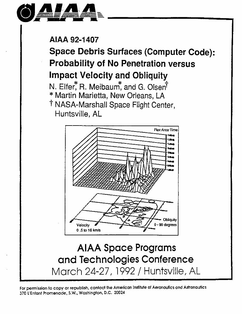
Space Debris Surfaces(Computer Code):Probability of NoPenetration versusImpact Velocity andObliquity.
Prepared for:National Aeronautics and Space AdministrationGeorge C. Marshall Space Flight CenterMarshall Space Flight Center,Alabama 35812
I. OC|IliiO
MAF/MMA 31-100 (3/95)
https://ntrs.nasa.gov/search.jsp?R=19960023925 2018-06-06T17:03:37+00:00Z

i
AIAA 92-1407
Space Debris Surfaces (Computer Code):Probability of No Penetration versus
Impact Velocity and ObliquityN. Elfe "_R Meibau_ and G Olsent
, " 1 "
Martin Marietta,t NASA-Marshall
Huntsville, AL
New Orleans, LASpace Flight Center,
I
L 0.5 to 16 krrVs "-"
AIAA Space Programsa]'_c:i Technologies Conference
March 24-27, 1992 / Huntsville, AL
For permission to copy or republish, contact the American Institute of Aeronautics and Astronautics370 L'Enfant Promenade, S.W., Washington, D.C. 20024


SPACE DEBRIS SURFACES:
PROBABILITY OF NO PENETRATION
VERSUS IMPACT VELOCITY AND OBLIQUITY
N. Elfer*,t, R. Meibaum*, G. Olsen**,t
AbstractA unique collectionofcomputer codes,Space
Debris Surfaces (SD_SURF), have been developed
toassistin the designand analysisofspace debris
protection systems. SD_SURF calculates and
summarizes a vehicle'svulnerabilityto spacedebris
as a functionofimpact velocityand obliquity.
An SD_SURF analysis will show which
velocitiesand obliquitiesare the most probable to
cause a penetration.This determination can help
the analystselecta shielddesignthatisbestsuited
to the predominant penetrationmechanism. The
analysisalsosuggeststhe most suitableparameters
fordevelopment orverificationtesting.
The SD SURF programs offerthe option of
eitherFORTRAN programs or MicrosoftEXCEL
spreadsheetsand macros.The FORTRAN programswork with BUMPERII. The EXCEL spreadsheets
and macros can be used independently or with
selected output from the SD_SURF FORTRAN
programs.Examples willbe presented ofthe interaction
between space vehiclegeometry, the space debris
environment, and the penetration and critical
damage ballisticlimitsurfacesof the shieldunderconsideration.
Space debris probabilitycodes, BUMPERII
and Space Debris Vulnerability(SDV), analyze a
space vehicleas a facetedgeometry.1"4These codes
calculatethe probabilityofno penetrationforeach
facet based on the exposure area and the
penetration resistance (ballisticlimit)to each
* Martin MariettaManned Space Systems,
New Orleans,LA 70189
t AIAA Member
** NASA Marshall Space FlightCenter,
Huntsville, AL 35812
Copyright O 1992 by the American Instituteof Aeronautics and
Astronautics, Inc. No copyright is asserted in the United Stat_
under Title 17, U.S. Code. The U.S. Government has a royalty.
free license to exercise all rights under the copyright claimed
herin for Governmental purposes. All other rights are reserved
by the copyright owner.
threat'simpact velocityand obliquity,as described
in the following sections.The output tellsthe
designerwhich areas are most vulnerable.
.En.zinmm_The space debris environment is defined in
terms of a flux of particles of diameter, d, or larger,dependant on the year of interest (due to assumedgrowth in the environment and solar flux varia-
tions) and the spacecraft altitude. 4 Figure 1 showsa flux versus d curve for typical parameters ofinterest.
Orbital Debris Flux
o.E
.,,--.
X
_=14.
10
0.1
0.001
0.0_01
0.0000001
0.001
SSP 30425
Year = 1998
Altitude = 388 km
Inclination = 28.5 =
Solar Flux - S = 10C
Flux Definition
(W'_hout
Collision
Avoidance)
W'lth10o%Collision
Avoidance
over 10 cm I
i IIIBIII i i Rill I I iK,Inl I I 111121 I I lUtEI
I
0.01 0.1 1 10 100
Minimum Debris Diameter [cm]
Fig. 1. Impact flux versus space debris diameter.
The space debrisenvironment may be modeledas a seriesofthreatsfrom discretedirections.For
low earth orbit (LEO), space debris may be
assumed toexistin circularorbits.This assumption
fixesthe orbitalvelocity.Debris cannot intercepta

spacecraftfrom more than approximately 10°above
orbelow a plane tangenttothe localEarth normal.Otherwise the debris would enter the Earth's
atmosphere and be removed as a threat.Therefore,
the relativeimpact velocityin LEO isdetermined
by the orbitalvelocity,Vo, and the intersection
angle,_, ofthe two orbits.The impact velocity,Vi,is:
.180°-0,Vi = 2 Vo- cost_J
Figure2 shows the fractionofthe totalfluxcoming
from angles relativeto the directionofflight.The
relativeimpact velocityforthe intersectionof 388
km orbitsisalsoshown on the plot.
150__ 4
__) VIIOCII 7 |bROIl]
lao .o.ol-p...p.01.0.o20.oo.o.o4-'I" o' s
Dt_n e_
Pilghl
210 330
Fr,¢Ucm et Total FhCll
2?0
Fig. 2. Angular and velocity distribution of flux.
BallisticLimitSurface
The spectrum of debrissizes,velocities,and
obliquitiesthat may impact a shield lead to a
varietyofpenetrationmechanisms. Figure 3 illus-
tratesa ballisticlimit surface for hypervelocity
impact on a multiwallshield.A projectilediameter
at a velocityand obliquityabove the surfacewill
penetratethe shield.A diameter below the surface
willnot penetrate the shield.There are several
penetrationmechanisms which are describedin
Fig.3. Changes in shieldparameters affecteach
penetrationmechanism differently.Therefore,itis
important for the designer to know what
penetrationmechanism has the greatesteffecton
the overallprobabilityofno penetration.
Itisnecessarytounderstand the consequences
of a penetration.A small penetration should beavoided because ofpotentialdifficultiesin finding
and repairinga leak.However, a smallpenetration
EO
O
Eelo
1.00,
0.00.
0.54
Velocity [km/s]
7.511
I - Singleparticlepenetration.2 - Fragmentpenetration.
90°
45°
0o14.5
Obliquity[degrees]
3 - Momentumfailureby bulgeorspell.4 - Ricochet,bumperfragmentspenetrate.
Fig. 3. Ballistic Limit Surface with multiplepenetration mechanisms.
does not resultin an immediate fatality.Critical
damage willbe definedas penetrationsresultingin
rapiddepressurizationas wellas catastrophiccrack
growth. There is a theoreticalthreat of bodilyinjurydue tofragments,but thisismuch lesslikely
and willnotbe treatedinthispaper.
For Space StationFreedom, the criticalhole
size for too rapid depressurization has been
estimated as 10 cm in diameter. To get this
diameter,eithera largeprojectileorpetallingofthe
hole isnecessary.Conservativefractureanalyses
predictthatlargepetalsmay lead to catastrophic
Eo
Q
EQ
o
0.54
Velocity [kzn/s]
1114.5
90°
45°
0•Obliquity
[degrees]
Fig. 4. Critical Damage Surfaces.
2

rupture rather than simple
depressurization.
A criticaldamage limitsurfacesis
presented in Fig. 4. At high velocitythereissufficientintermediatethermal
blanket/shieldto prevent crateringor
spall, and the rear wall fails by
momentum induced bulging and
petalling.This can open a hole or
propagatea cracktoa much largersizethan the initialdamage area. The
projectilediameter to cause critical
damage was estimatedtobe 50% larger
than the projectilediameter to cause
penetration. For low velocity
penetrationthe projectedarea of the
projectile,plus a damage zone, is Iassumed to control criticaldamage. IThis is a very rough assumptionbecause thereisinsufficientdata about
the momentum deposited in the rearwall.The estimate of the size of the
damage zone willnot have a stronginfluenceon the
overallprobabilitybecause ofthe large projectilesize.
An alternative high-velocity penetrationmechanism may be wide area spall.A larger
particlewould then be necessaryto drivepetalling
and crackgrowth inthe rearwall,because much ofthe momentum willbe transferredto the spall
fragment.To estimate the influenceofthisfailure
mechanism, the projectilediameter was assumed tobe 225% of the ballisticlimit diameter for the
followingcalculations.
Model Generation
* SupertabNASTRANtranslator
I GEOMETRY• Space Debris• Meteoroids
ProbabilityAnalysis
The probabilityofno penetration(PNP) fromeach directionand foreach element isbased on the
Poissondistributionforzeroevents:
( nthreats
PNPel = exp[- Z(Ni.Ai)'tI
\ i=l l
where (withconsistentunits)
Ni = flux that penetrates from each threat
direction,i,
= 4-fi.Nr(di).
Nr = flux on a randomly tumbling plate
(specificationdefinition)of diameter d or
larger,di isthe diameter to penetrateat
the velocity and obliquity of the ith
threat.
fi = fractionoffluxfrom threatdirection.
RESPONSE I
• Space Debris• Meteoroids
I+ I
SHIELD I,e Space DebrisMeteoroid8
Fig. 5. BUMPERII Modules, Input and Output.
A i = projected area of the facet in the fluxdirection.
t = exposuretime.
The totalPNP isdetermined by the productof
the PNP foreach element.
nelements
PNPtotal = I'_PNPj
j=l
Figure 5 shows the BIYMPERII modules and
their input and output as they calculatePNP.
BUMPERII startswith a SuperTab output file
finiteelement model ofthe spacecraR.The GEOMETRY module of BUMPERII
calculatesthe projected area of the elements
exposed toeach threatdirection.A significantpart
of thiscalculationis intercomponent shadowing.
This can be a very time consuming processfor a
largemodel.The RESPONSE module creates a ballistic
limit surface from a menu of user selected
penetrationequations.The ballisticlimitforeach
shieldofinterestisstoredin a matrix forevery0.25
km/s and 5° obliquity.This isalsostoredinbinaryform in the computer. Another BUMPERII code,
RPLOT, reads the binary fileand puts out a
formattedfilewith the ballisticlimitat 0°,15°,30°,
45°,and °60 obliquityfor2D plots.The SHIELD module calculatesthe PNP for
any range of element numbers requested by the
analyst.SHIELD alsohas an option to create a
SuperTab fileto plotprobabilitycontours on the
originalgeometry model.
3

SD SURF Analysis Annroach
To design the most effective shield, theanalyst must know which penetration or damagemechanism is predominant. It is the goal of theSD_SURF computer programs to provide thisinformation.
The flux associated with each point on the
ballistic limit surface can be weighted by the prob-ability of an impact at that particular velocity andobliquity.
PNP(V,6) = exp[-N(d).A(V,6).t]
where A(V,6)isthe totalarea ofthe spacecraftthat
willbe impacted at an obliquity,6,from a debris
particle at velocity,V, and N(d) is the fluxassociatedwith the diameter d thatjustpenetrates
atV and 6.There isa differencein the PNP calculatedfor
a unitarea ata singlevelocityand obliquityversus
distributingthe area overtwo bracketingvelocities
and two bracketingobliquities.This is due .tothe
non-linearrelationshipbetween fluxand diameter.
On the other hand, the analysis of a curved surfacein BUMPERII is more accurate only if the size ofthe facets is smaller than the five-degree incre-ments used on the RESPONSE and AREASURFACE tables.
SD SURF - FORTRAN Version
The interrelationship of the FORTRANmodules of SD_SURF is shown in Fig. 6. SD_SURFacts as a post-processor of BUMPERII-RESPONSEand GEOMETRY output. It provides additionalinformation not readily obtainable fromBUMPERII.
The A_SURF module reads the BLrMPERII-
GEOMETRY binary output to create the exposedarea matrix as a function of velocity and obliquity.Rather than lump the area of one facet at thenearest velocity and obliquity, A_SURF uses thelever rule to distribute the projected area, for onefacet and one threat, over the four nearestvelocities and obliquities. The sum of the exposedareas is equal to the area reported by BUMPERII.
The A_SURF module puts out both anunformatted file and a formatted file. The unfor-
matted binary file can be read by the P_SURFmodule. The formatted text file can be used to
check the output manually, or it can be read by theEXCEL modules as described in the next section.
The P_SURF module reads in the A_SURFand RESPONSE output files, and uses the sameflux routines in BUMPERII-SHIELD to calculate
the flux.area.time (NAT) array. A text based con-
tour map is generated, which should be compatible
with any FORTRAN platform, and also a text filethat may be used with sophisticated graphics pack-
ages. Examples of the contour plots will be shownin the examples in the next section of this paper.
The final FORTRAN module is R_PLOTS. It is
used to translate BUMPERII-RESPONSE outputfiles to text formatted files. The text formatted file
is set up at 0.5 km/s and five-degree incrementsrather than the 0.25 km/s and five-degree incre-
ments used by RESPONSE. Commas are used asdelimiters to ease import by the EXCEL modules.
SD SURF - EXCEL 3.0 Version
The EXCEL version can be used both as an
alternative or a complement to the FORTRANversion. The EXCEL version is not as fast or as
"turnkef' as a FORTRAN application. However, ithas the advantages of a spreadsheet: customized
calculations and analyses are simple to generate;error checking is very easy; there is quick access tographing.
The structure of the EXCEL version is shown
in Fig. 7. The backbone of the PNP calculation isthe PNP_Template. There are several differentareas on the worksheet:
• Ballistic Limit surface, diameter to penetratein increments of 0.5 km/s and five degrees ofobliquity. (It is created on a Ballistic LimitTemplate or imported from RESPONSE viaR_PLOT 5.)
• Environment definition including year, solarflux level (explicit or calculated), and altitude.
• Flux calculation for each diameter in the
ballistic limit surface. (This is a function macrothat is defined on the function macroworksheet.)
• Area Surface, A(V,6), created usingArea_Maker Macro, or imported fromA_SURF.
• Flux • Area • Time, N.A.T, for each V and 6.(The summation of these cells is used to
calculate the PNP.)
Function macros operate as subroutines andare used to calculate ballistic limits or flux for
appropiate input values. Command macros provide
control of files and the pasting of named arraysfrom ballistic limit and area templates to the PNP_Template.Any ofthe templatesmay be customized
and saved by any name forlateruse.Hardcoding
the names would make iteasierfora new user,but
the flexibilityprovidedby usinggeneralnames was
deemed tobe more important.
4

Model Generation• Supertab• NASTRAN
translator
I GEOM II Space Debn_ i[ • Meteoroids J ,
A_SURFArea Fraction Table• Space Debris
by vel. and obl.[binary]
by vel. and obl.
SURF(FORTRAN vers.)• Space debris only• BUMPERII flux
subroutines
PNP by range• Flux.Area.time
by vel.and obl.[formatod]
RESPONSE• SpaceDebris• Meteoroids
Y:i BUMPERII ]
Program
Fig. 6. SD_SURF - FORTRAN and BUMPERII Modules, Input and Output.
Optional Input fromFORTRAN programs:
R PLOT5 Output
A_SURF Output
by vel.and obl.formated]
SD_Surf EXCEL vers. (o_5 km/s by 5 degree increments)Command Macros Function Macros• Create Pull Down Menus • Ballistic Limit calculations• Dialog boxes and messages * Flux calculations• Open/Save files and templates Templates• Control order of calculation • Prodofined areas, calculations• Cut and paste from templates and formats
I BI_Macro Template P_NP/Flux Templa_
• Function Macro
• Paste truing SD_SURF Obliquit 7 .
V Ballistic Limit iBL-RPLOT Template •• Open and Pasteusing I
SD_SURF Macro
AREA Template
Area_Ma fills in template 0Vel. Distrib. function
Direct from text file i
uJing Aroa_Maker j
0
¢
it
;Y
Flux (d, environment t
• Function macro I
Fig. 7. SD_SURF - EXCEL and SD_SURF - FORTRAN Modules, Input and Output.

The Area Surface maybe created on the
Area_Template using the Area_Maker Macro. The
analyst selectsthe geometry desiredfrom a pull-
down menu. The standard geometriesare shown in
Fig. 8. The specificgeometry is entered in cus-
tomized dialogboxes.Each facetisanalyzedateach
velocityincrement.This iseffectively64 threats(at
equally spaced velocities),compared to the 45threatdefaultinBUMPERII.
SD_SURF for EXCEL lacks some of the
featuresof BUMPERII. BUMPERII must be used
for shadowing analysisin GEOMETRY, multiyear
flux averaging in SHIELD, or the extensive itera-tions required to run PEN4 in RESPONSE.However, the GEOMETRY and RESPONSE outputmay be imported via the FORTRAN A_SURF and
R_PLOT5 programs. Multiyear flux calculationscan be programmed into the EXCEL macros with a
corresponding increase in analysis time.
Probability Studies
The A_SURF program and the Area-Template
calculatethe effectiveexposed area at each velocity
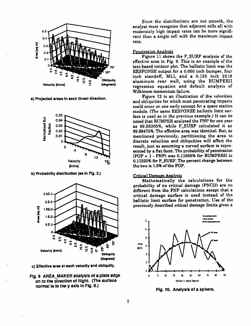
and obliquity.Figure 9 illustratesthe analysisofa
fiatplatethatisorientededge on tothe directionof
flight (90 degrees yaw in Fig. 8). The first part ofthe analysis is the calculation of the projected area
relative to each impact velocity direction. Figure 9(b) shows the probability associated with each
impact velocity. Figure 9(c) shows the final resultafter multiplying the projected areas by the relativeprobability.
A_SURF reveals the coarseness, or granular-ity, in the spacecraft model and debris threat in theGEOMETRY analysis. The default of 45 threat
directions in BUMPER gives only 22 velocities due
to symmetry. This will produce gaps along thevelocity axis. _Waves" on the surface are an artifact
of the coarseness of the modelling. The sphere is aneasy shape to analyze since it looks the same from
any direction. (That is why it is a separate option inthe AREA_Maker macro.) The projected area fromany direction is shown in Fig. 10. Also shown is itsappearance if it were modelled using facets thatcover15 degreesof curvature.The granularity,orwavinessisobvious.
The sphereisalsoa good representationofthe
surfacearea of any spacecraftthat is not Earth
oriented.Itwillappear tobe randomly tumbling to
the debrisflux and average out to the obliqueimpactson a spherewiththe same surfacearea.
AXE5 ROTATION RECTANGLE DI5K
II P_¢h "r_w I L'I Radius = L1
or I1¥ I\x T x I x
11CYLINDER SPHERE CONE
1Note: 5tart and stop angles are shown positive starting from zero (heavy line).
Negative numbers may be used. (Eg. -90 to 90 for *y Side Of cylinder.)
Cone anti cylinder are not symmetric. O" to 5" does not also generate 175" to 180".
The difference in the start 2nd stop angles must De evenly divisible by the tncremenL
Fig. 8 AREA_MAKER Available Geometries
E
E4(
O.S
0,4
0.3
0.2-
0.1
0
O _
Velocity [knVs]
a) Projected areas in each threat direction.
: 0.04.q:
o.03.0.02 •
_= 0.01
12
voloc [knVs]
b) Probability distribution (as In Fig. 2.)
_' 1.5E-2.
=r1.E-2.
9(5.E-3 -
¢%1
ObliquityId,,g,_sI
c) Effective area at each velocity and obliquity.
Fig. 9 AREA_MAKER analysis of a plate edgeon to the direction of flight. (The surfacenormal Is in the y axis In Fig. 8.)
Since the distributionsare not smooth, the
analystmust recognizethatadjacentcellsallwith
moderately high impact ratescan be more signifi-
cant than a singlecellwith the maximum impact
rate.
penetrationAna]vsis
Figure 11 shows the P_SURF analysisofthe
effectivearea in Fig.9.This isan example ofthe
text-basedcontourplot.The ballisticlimitwas the
RESPONSE output fora 0.050 inch bumper, four
inch standoff, MLI, and a 0.125 inch 2219
aluminum rear wall, using the BUMPERII
regression equation and default analysis ofWilkinsonmomentum failure.
Figure 12 is an illustrationof the velocities
and obliquitiesforwhich most penetratingimpacts
couldoccuron one earlyconceptfora spacestationmodule. (The same RESPONSE ballisticlimitsur-
faceisused as in the previousexample.)Itcan be
noted thatBUMPER analyzedthe PNP forone year
as 99.88305%, while P_SURF calculated it as99.88475%.The effectiveareawas identical.But,as
mentioned previously,partitioningthe area to
discretevelocitiesand obliquitieswillaffectthe
result,justas assuming a curved surfaceisrepre-
sentedby a fiatfacet.The probabilityofpenetration(POP : 1 - PNP) was 0.11695% for BUMPERII to
0.11525% forP_SURF. The percentchange betweenthe two is1.5% ofthe POP.
CHticalDnma_e AnalysisMathematically the calculations for the
probabilityof no criticaldamage (PNCD) are nodifferentfrom the PNP calculationsexcept that a
criticaldamage surface is used instead of the
ballisticlimitsurface forpenetration.Use of the
previouslydescribedcriticaldamage limitsgivesa
tlm4mmwl_m
1 mmll_
_1_1 wal i_um4 aN
'0
5
/_ea
imP216
4
2
0
0 "0 20 _ 40 50 _ 70 80 90
O_)lt_Jl:)' Angle [Oegree
Fig. 10. Armlysis of a sphere.
7

O
E
k
a14.
Obllqulty
[degrees]
Fig. 11. P_SURF analysis of flat plate In Fig. 9.
PNCD of 99.965 and 99.985, for momentum tearingand spall failure mechanisms respectively.Comparison of the probability of critical damage tothe probability of penetration (POCD/POP) showsthe chance of a critical failure if penetration shouldoccur. This ranges between 10% and 25%, depend-ing on the critical damage limit that is used.
It may be noted that the environment defini-tion does not include collision avoidance for track-
able debris (> 10cm). This may not be significant for
O
E
i===
,T
tO
¢q
Velocity [kin/s]
a) EXCEL Graph
P
Obliquity
[degrees]
Fig. 12. P_SURF analysis of a SSF module.
penetration of the baseline design, but collisionavoidance can affect the flux of particles capable of
causing critical damage.
The SD_SURF collection of computer codes
provides valuable design information:
• The most likely velocities and obliquities tocause a penetration are displayed. This isuseful in shield selection and verification.
= Granularity in the model facets and assumedthreat environment is displayed. Plots alsoprovide an overall "sanity check" on themodel.
An additional benefit of the structure of thecode is that the intermediate results are contained
in fairly small matrices. This allows the followinguses:
° Computations may be made in easily
modifiedspreadsheets.
• Fast recalculation is possible for opti-mizationstudies.
Acknowledgements
Two of the authors (Elfer and Meibaum) grate-fully acknowledge support for this work undercontract NAS8-38856. The authors also wish to
acknowledge the support and guidance of severalpeople in particular: Joel Williamsen, JenniferRobinson, Scott Hill and Sherman Avans.
_J_: 11 _ r_z: 30_050HB_S._
A _ F'JZ: M_I7-ALL.AS8
mUm(t)- 99.884"75 _ _ x _ x ¢_e rm#1 - 0.11532E-02
.12.345 at. e¢luaJ. _ _ 0 ¢,o mfx _ - 0.26100K-04
IMPA(_ _ km/s
CI_ 1 2 3 4 5 6 7 8 9 10 1.I 12 1.3 "t4 15 16
.Oeg I 1 Z 1 1 1 I I I I I Z I I T I
90 ................................................................
75 .............................. 1 ...... i..1 ..... l..I.i ............
i i
65 ........................................ 1..1..2..2.!.212 ........
60 ...................... l...2...!..i...i ..... !..2..2.51/2 .........
55 .......................... 1 ............. i..11.3._ ............
I • .50 .................................. i..3..2..21.51.3 .............
45 .......................... 1...2..1 ...... 31.41.1 .................
40 ..................................... 5..3 .......... ! ............
35 .............................. 2..!i..i ........... i ..............
30 ................................................................
2_ ..................................... l ..........................
20 .................. i ..................... ! .......................
1.5 ........................................... 4..4 ................
I0 _ .I ..............
5 ................................................ I
0 ................................................................
b) FORTRAN Text Plot
(1995 exposure environmem).

I. Coronado, A_ et al.:"Space StationIntegrated
Wall Design and PenetrationDamage Control,"
Contract NAS 8-36426,NASA-Marshall Space
FlightCenter,1987.
2. Graves,Russel:BumperlI User'sManual.
3. Elfer,N.; et al.Martin Marietta IR&D M-01S,
unpublishedresearch,1987.
4. "Space StationProgram Natural Environment
DefinitionforDesign,"NASA SSP 30425.
5. Elfer,N.;and Rajendran, A. M.: "Space Debris
Protection,n in T. Wierzbicki,N. Jones Eds.
StructuralFailure,John Wiley & Sons, New
York, p.41-78,1989.
9