Embed Size (px)
Citation preview

OCEANUS-6 SERIESHANDBOOK
ISSUE 5 - 01/05
Page 1 of 43
OCEANUS-6 SERIESMODEL 580
This manual is issued under the authority ofMr. J.P. Tavener, Managing Director
The company is always willing to give technical advice and assistance where appropriate.Equally, because of the programme of continual development and improvement we reserve theright to amend or alter characteristics and design without prior notice. This publication is forinformation only.
Isotech North America158 Brentwood Drive, Unit 4 Colchester, VT 05446
Phone: 802-863-8050 Fax: 802-863-8125
OCEANUS-6 SERIESHANDBOOK
ISSUE 5 - 01/05
Page 2 of 43
CONTENTS
PAGE DESCRIPTION
3 - 4 EMC Information5 Health & Safety Instructions6 Do’s and Don’ts7 Guarantee8 Cautionary Note9 Unpacking & Initial Inspection10 - 12 Introduction13 - 15 Mode of Operation16 Adjusting the Timer17 - 18 Using Water & Gallium Fixed Point Cells19 - 20 Thermometric Fixed Points (a tutorial note)21 How to measure the true temperature inside the accessories
supplied with the Isocal-622 Specification23 Performance Graph24 - 25 Operation26 - 28 Altering the Ramp Rate29 Determining the Calibration Data30 - 31 Connecting a current transmitter (up to 20mA)
Testing Thermostats32 Using the PC Interface33 - 34 Using the Cal Notepad 35 Diagnostics36 Initial Testing37 Maintenance38 Figure 139 Appendix 1 - Trouble Shooting40 - 41 Appendix 2 - Indicator Configuration42 - 43 Appendix 3 - Accessories
OCEANUS-6 SERIESHANDBOOK
ISSUE 5 - 01/05
Page 3 of 43
EMC INFORMATION
This product meets the requirements of the European Directive on ElectromagneticCompatibility (EMC) 89/336/EEC as amended by EC Directive 92/31/EEC and the EuropeanLow Voltage Directive 73/25/EEC, amended by 93/68/EEC. To ensure emission complianceplease ensure that any serial communications connecting leads (RS232 or RS422(485)) arefully screened.
The product meets the susceptibility requirements of EN 50082-1, criterion B.
Symbol Identification Publication Description
ISO3864 Caution (Refer to Handbook)
IEC 417 Caution, Hot Surface
ELECTRICAL SAFETY
This equipment must be correctly earthed.
This equipment is a Class 1 Appliance. A protective earth is used to ensure the conductiveparts can not become live in the event of a failure of the insulation.
The protective conductor of the flexible mains cable which is coloured green/yellow MUST beconnected to a suitable earth.
The blue conductor should be connected to Neutral and the Brown conductor to Live (Line).
OCEANUS-6 SERIESHANDBOOK
ISSUE 5 - 01/05
Page 4 of 43
Warning: Internal mains voltage hazard. Do not remove the panels.
There are no user serviceable parts inside. Contact your nearest Isotech agent for repair.
Voltage transients on the supply must not exceed 2.5kV.
Conductive pollution, eg. Carbon dust, must be excluded from the apparatus. EN61010pollution degree 2.
The apparatus has two input connectors for temperature sensors, see Figure 1. These inputsare only suitable for either a thermocouple or resistance thermometer. No other sensor orsignal may be connected.
ENVIRONMENTAL RATINGS
Operating Temperature 5-50/C
Relative Humidity 5-95%, non condensing
OCEANUS-6 SERIESHANDBOOK
ISSUE 5 - 01/05
Page 5 of 43
HEALTH AND SAFETY INSTRUCTIONS
1. Read all of this handbook before use.
2. Wear appropriate protective clothing.
3. Operators of this equipment should be adequately trained in the handling of hot andcold items and liquids.
4. Do not use the apparatus for jobs other than those for which it was designed, ie. thecalibration of thermometers.
5. Do not handle the apparatus when it is hot (or cold), unless wearing the appropriateprotective clothing and having the necessary training.
6. Do not drill, modify or otherwise change the shape of the apparatus.
7. Do not dismantle the apparatus.
8. Do not use the apparatus outside its recommended temperature range.
9. If cased, do not return the apparatus to its carrying case until the unit has cooled.
10. There are no user serviceable parts inside. Contact your nearest Isotech agent forrepair.
11. Ensure materials, especially flammable materials are kept away from hot parts of theapparatus, to prevent fire risk.
OCEANUS-6 SERIESHANDBOOK
ISSUE 5 - 01/05
Page 6 of 43
OCEANUS-6 MODEL 580
‘DO’S AND DON’TS’
DO NOT handle the accessories when they are very hot or very cold.
DO NOT place hot or cold accessories back in the carrying case
DO NOT use the pocket designed for the black body source sensor to measure the temperatureof the insert, stirred liquid bath or surface calibrator.
DO use that pocket for pre-warming, pre-cooling or storage.
DO NOT spill liquids inside the Oceanus-6
DO NOT use liquids outside their recommended temperature range
DO NOT use viscous liquids in the stirred liquid accessory, the stirring will be restricted andlarger gradients will occur.
DO NOT mix liquids. If you are using 1 container for different liquids make sure the containeris completely clean and dry before adding another liquid.
DO NOT worry if the black anodising gets discoloured or scratched. We can supply somespecial black touch up paint.
DO NOT rely on the controller to tell you the temperature of the insert or stirred liquid bath. It’sjob is only to provide an isothermal volume. It is the calibrated working standard that is usedto measure actual temperature.
DO NOT calibrate very large sensors in the Oceanus-6 unless you can accept large immersionerrors. We have larger products for larger sensors.
DO NOT try to straighten the working standard, it is deliberately bent so that it does notinterfere with the sensors you are calibrating.

OCEANUS-6 SERIESHANDBOOK
ISSUE 5 - 01/05
Page 7 of 43
GUARANTEE
This instrument has been manufactured to exacting standards and is guaranteed for twelvemonths against electrical break-down or mechanical failure caused through defective
material or workmanship, provided the failure is not the result of misuse. In the event offailure covered by this guarantee, the instrument must be returned, carriage paid, to the
supplier for examination and will be replaced or repaired at our option.
FRAGILE CERAMIC AND/OR GLASS PARTS ARE NOT COVERED BY THISGUARANTEE
INTERFERENCE WITH, OR FAILURE TO PROPERLY MAINTAIN THIS INSTRUMENTMAY INVALIDATE THIS GUARANTEE
RECOMMENDATION
The life of your ISOTECH Instrument will be prolonged if regular maintenance and cleaningto remove general dust and debris is carried out.
Serial No:.............................................
Date:.....................................................
Isotech North America158 Brentwood Drive, Unit 4 Colchester, VT 05446
Phone: 802-863-8050 Fax: 802-863-8125
OCEANUS-6 SERIESHANDBOOK
ISSUE 5 - 01/05
Page 8 of 43
CAUTIONARY NOTE
ISOTECH PRODUCTS ARE INTENDED FOR USE BYTECHNICALLY TRAINED AND COMPETENT PERSONNELFAMILIAR WITH GOOD MEASUREMENT PRACTICES.
IT IS EXPECTED THAT PERSONNEL USING THISEQUIPMENT WILL BE COMPETENT WITH THEMANAGEMENT OF APPARATUS WHICH MAY BE POWEREDOR UNDER EXTREMES OF TEMPERATURE, AND ARE ABLETO APPRECIATE THE HAZARDS WHICH MAY BEASSOCIATED WITH, AND THE PRECAUTIONS TO BE TAKENWITH, SUCH EQUIPMENT.
OCEANUS-6 SERIESHANDBOOK
ISSUE 5 - 01/05
Page 9 of 43
UNPACKING AND INITIAL INSPECTION
Our Packing Department uses custom designed packaging to send out your unit, but asaccidents can still happen in transit, you are advised, after unpacking the unit, to inspect it forany sign of shipping damage, and confirm that your delivery is in accordance with the packingnote. If you find any damage or that part of the delivery is missing notify us or our agent, andthe carrier immediately. If the unit is damaged you should keep the packing for possibleinsurance assessment.
ELECTRICITY SUPPLY
Before connecting to the electricity supply please familiarise yourself with the parts of thehandbook relevant to your model.
Your unit's supply voltage requirement is specified on a plate on the instrument along with theserial number. All Oceanus-6 instruments will work on an electricity supply frequency of 50Hzor 60Hz.
The apparatus is provided with an approved power cord. If the plug is not suitable for yourlocation then the plug should be removed and replaced with an appropriate plug.
Take care to ensure the old plug is disposed safely.
The cable is colour coded as follows:
COLOUR FUNCTION
Green/yellow Earth (Ground)Brown Live (line)Blue Neutral
Please ensure that your unit is correctly connected to the electricity supply.
THE APPARATUS MUST BE CORRECTLY EARTHED (GROUNDED)
The units on/off switch is located on the power inlet. Take care NOT to switch the unit off whenit is hot - allow to cool first.
OCEANUS-6 SERIESHANDBOOK
ISSUE 5 - 01/05
Page 10 of 43
INTRODUCTION
The Oceanus-6 range of products allows unprecedented flexibility for the calibration oftemperature sensors. The Oceanus-6 range may be used with the following options:
1. An ITS-90 Fixed Point Apparatus2. As a Metal Block Bath3. As a Stirred Liquid Bath4. As a Stirred Ice Bath5. A Black Body Source6. A Surface Sensor Calibrator
The Oceanus-6 is available in two variants. The Basic (B) model which incorporates a singletemperature controller. The Potts as Site (S) model also include a temperature indicator anda timer.
COMPARISON CALIBRATION:
By definition, one compares industrial thermometers to a calibrated standard.
There are 3 methods commonly used.
1) USING THE CONTROLLER
Using the controller as the “calibrated standard” this method means that the complete bath iscalibrated by comparing the controller reading to a calibrated standard placed in the bath.
This is a common method but is unsafe since the control sensor is
a) inaccessibleb) in the wrong place to give correct temperature of the insert
For these reasons it fails to satisfy ISO9000 and gives large uncertainties.
OCEANUS-6 SERIESHANDBOOK
ISSUE 5 - 01/05
Page 11 of 43
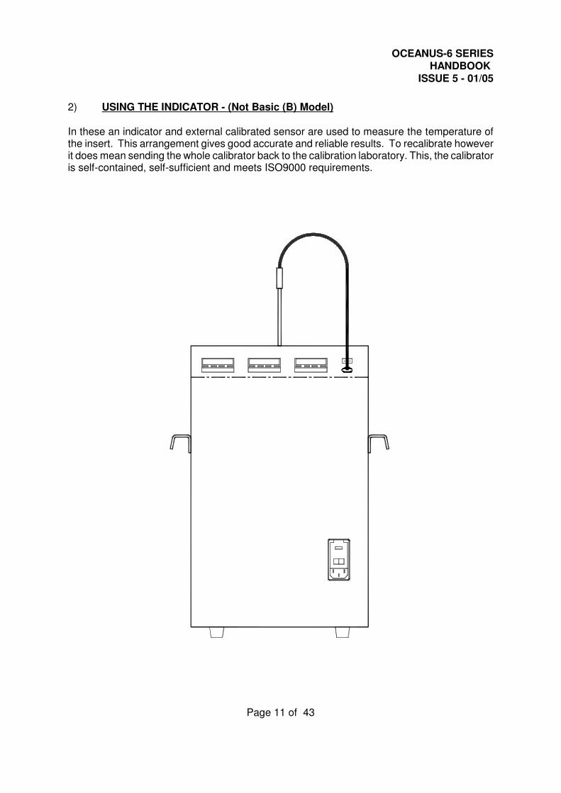
2) USING THE INDICATOR - (Not Basic (B) Model)
In these an indicator and external calibrated sensor are used to measure the temperature ofthe insert. This arrangement gives good accurate and reliable results. To recalibrate howeverit does mean sending the whole calibrator back to the calibration laboratory. This, the calibratoris self-contained, self-sufficient and meets ISO9000 requirements.

OCEANUS-6 SERIESHANDBOOK
ISSUE 5 - 01/05
Page 12 of 43
3) USING EXTERNAL STANDARDS
Here a separate indicator and calibrated sensor are used to measure the inserts temperature.This can give the most accurate and reliable results, depending on the indicator.
It means that the calibrator does not need calibrating only the indicator and it’s calibratedsensor need re-calibration, but this option is more bulky, expensive and less portable than 2)above. It also meets ISO9000 requirements.
OCEANUS-6 SERIESHANDBOOK
ISSUE 5 - 01/05
Page 13 of 43
MODE OF OPERATION
1) ITS-90 FIXED POINT CALIBRATION
The ITS-90 fixed point function of the Oceanus-6 is well suited for fast, convenient, mess freecalibration of thermometers to uncertainties as low at 0.001/C.
The special cell is placed into the Oceanus-6 calibration well. The stir speed control should beset to the OFF position.
The equipment incorporates a timer which can change temperatures to allow MELTING orFREEZING of a Gallium Cell. Once initiated the Cell can be arranged to be on the melt plateauduring the day and automatically frozen and bought back to the melt plateau overnight.
For use with a Gallium Cell the well temperature should be 30.5/C for the MELT or 15/C for theFREEZE.
On power up the timer is set to run at setpoint 1 for 20 hours at setpoint 2 for 4 hours.
2) METAL BLOCK BATH
The metal block bath function of the Oceanus-6 is well suited for fast, convenient, mess freecalibration of temperature sensors.
The Oceanus-6 metal insert is placed into the calibration well. The stir speed control shouldbe set to the OFF position (turn fully anti-clockwise).
The thermometers under test are placed into suitable holes in metal insert (part number 580-06-03), see accessory section page 40. A calibrated reference probe should be placed into theinsert and the actual temperature can be read from the temperature indicator.
For traceable calibration the actual value of the insert temperature should be recorded alongwith the values from the sensors under test.
OCEANUS-6 SERIESHANDBOOK
ISSUE 5 - 01/05
Page 14 of 43
3) STIRRED LIQUID BATH
The stirred liquid bath function of the Oceanus-6 is well suited for odd shaped sensors whichwill not easily be accommodated in a metal insert.
The Oceanus-6 Liquid Container (part number 580-06-07) is placed into the calibration well andthe container is filled with a suitable liquid, see accessory section page 40 for the temperaturerange that the bath is to be used over. The container should be filled to 25mm from the top ofthe tank. Care must be taken to adjust the level as the liquid contracts or expands withtemperature changes. The stirrer speed control is set ON and to the mid position. If necessarythe speed to can be adjusted to give the optimum value for a particular application, this positionshould be found experimentally and then noted for future use.
The thermometers under test are placed into the liquid. Two accessories are available tosupport the thermometers.
a) The Thermometer Support Kit (part number 580-06-00) allows thermometers with adiameter of 2 to 6.5mm to be suspended in the liquid.
b) The Sensor Guide which fits into the tank and can support a number of thermometers(part number 580-02-16).
It is important that one of the accessories is used to prevent the probes from reaching thebottom of the tank which would stop the stirring action. A calibrated reference probe shouldbe placed into the liquid and the actual temperature can be read from the temperature indicator.
For traceable calibration the actual value of the liquid temperature should be recorded alongwith the values from the sensors under test.
4) STIRRED ICE BATH
The Stirred Ice Bath function is as the Stirred Liquid Bath. The liquid container - part number580-06-07 is filled with water, the stirrer speed control set to mid-position and the controller setto 0.0/C. Once the controller has stabilized at 0.0/C allow 10-15 minutes before startingcalibration.
OCEANUS-6 SERIESHANDBOOK
ISSUE 5 - 01/05
Page 15 of 43
5) BLACK BODY SOURCE
The black body function of the Oceanus-6 is well suited for fast, convenient, mess freecalibration of infra-red temperature sensors.
The Oceanus-6 black body target (part number 580-02-12), see accessory section page 40 isplaced into the calibration well. The stir speed control should be set to the OFF position.
The units under test should be aligned with the target.
A calibrated reference probe should be placed into the hole in the block and the actualtemperature can be read from the temperature indicator to which the infra red thermometer(s)are compared.
6) SURFACE SENSOR CALIBRATION
The surface sensor function of the Oceanus-6 is well suited for fast, convenient, mess freecalibration of most surface temperature sensors.
The Oceanus-6 surface sensor insert (part number 580-02-11), see accessory section page40, is placed into the calibration well. The stir speed control should be set to the OFF position.
A calibrated probe (part number 935-14-84) is placed in the pocket of the surface sensor insertand connected to the temperature indicator. Surface sensors are placed on top of the insertand when stable compared to the calibrated probe.
OCEANUS-6 SERIESHANDBOOK
ISSUE 5 - 01/05
Page 16 of 43
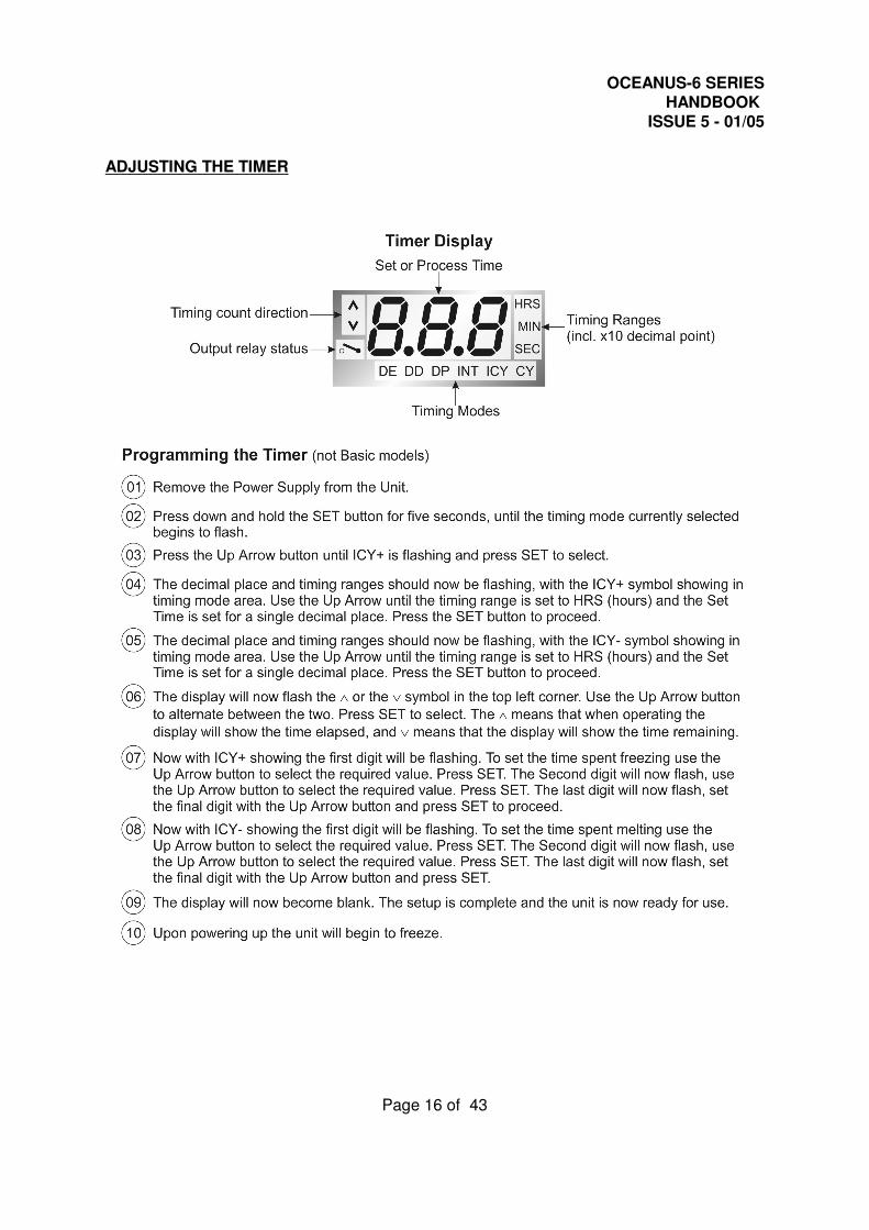
ADJUSTING THE TIMER
OCEANUS-6 SERIESHANDBOOK
ISSUE 5 - 01/05
Page 17 of 43
USING WATER & GALLIUM FIXED POINT CELLS
WATER TRIPLE POINT CELL
The adapter rings should be fitted above and below the cell so that the cell sits centrally in theblock. The top of the well should then be thermally insulated with foam expanded polystyrene,tissue paper etc.
Switch on the Oceanus and set the temperature to -7/C. The Oceanus-6 will cool much quickerthan the cell because there is an air gap between the cell and the block, therefore monitor thetemperature of the cell using a thermocouple or resistance thermometer inside the cells re-entrant tube.
When the cell has reached about -6/C gently remove the cell from the Oceanus-6 andsupporting the base of the cell in one hand, gently flick the top of the cell to one side, whereupon ice forms and the temperature rises to the triple point value. In order to stabilise the icemush which tends to rise to the surface, the cell is returned to the bath at -7/C. It is left therefor ten minutes to stabilise. The cell is then briefly removed from the block. A small amountof ambient temperature alcohol introduced into the reentrant tube of the cell (washing thereentrant tube walls as it is introduced) will free the ice mantle from the reentrant tube. Theouter surface of ice is then warmed by hand until the sheath of ice is free to rotate. A gentleaxial twist of the cell will confirm the mantle is free. The cell is returned quickly to the Oceanus-6block and the temperature increased to about -1/C. This gradually causes the ice to grow backto the outer wall of the cell and compensates for coolth losses from the thermometers beingcalibrated.
The cell should be periodically inspected and if necessary, the ice sheath freed from the wallof the cell.
There is nothing sacrosanct about the above procedure and provided between a and b of thecell is ice then the triple point calibration is valid.
The best temperature to maintain the cell can be found only after use.
It will depend on:
1. The number of sensors being calibrated.2. The ambient temperature.
If, at any time, an ice bridge forms on the surface of the water in the cell, the cell may rupture.The likelihood of this happening is small since the surface of the cell is above the block of theOceanus-6, however the cell should be checked regularly.
The accuracy with which the cell may be used to check a thermometers calibration may, inpractice, be limited by the extent of its immersion in the cell, or by the self-heating of thethermometer. The magnitude of these effects may be checked (i) by reducing the immersiondepth and (ii) by making measurements at two currents through the thermometer.
OCEANUS-6 SERIESHANDBOOK
ISSUE 5 - 01/05
Page 18 of 43
LARGE GALLIUM CELL
The adapter rings should be fitted above and below the cell so that the cell sits centrally in theblock. The top of the well should then be thermally insulated with foam expanded polystyrene,tissue paper etc.
Set the Oceanus-6 to give a well temperature of approximately 32/C. Monitor the Cell until theGallium starts to melt, at this stage the well temperature can be lowered to 30.5/C which willgive a long melt plateau.
This two step procedure will lead to a rapid melt and long plateau. At the end of the plateau thesetpoint should be set to 15/C to freeze the Cell. It is essential the Cell freezes from the bottomupwards. Leaving the Cell in the Oceanus-6 until it is frozen will ensure this happens andeliminates the possibility of the cell being damaged by the expansion of the Gallium during thefreeze.
NB. For the flattest melt plateau, remove the cell from the Oceanus-6 and freeze by standingthe bottom third of the cell in crushed ice or an ice/water mixture. Once frozen it can be meltedas before but first make sure the cell is thoroughly dry before re-introducing into the Oceanus-6.
The operation can be automated - see page 24.
The accuracy with which the cell may be used to check a thermometers calibration may, inpractice, be limited by the extent of its immersion in the cell, or by the self-heating of thethermometer. The magnitude of these effects may be checked (i) by reducing the immersiondepth and (ii) by making measurements at two currents through the thermometer.
SLIM GALLIUM CELL
Please see separate handbook for this cell.

OCEANUS-6 SERIESHANDBOOK
ISSUE 5 - 01/05
Page 19 of 43
THERMOMETRIC FIXED POINTS (a tutorial note)
Temperature scales used in science and industry are defined by a series of "fixed points", whichare realised by establishing thermal conditions under which pure materials exhibit equilibriumbetween two or three phases. A scale assigns numerical values to the temperatures at whichthese phase equilibria exist. For example, the temperature at which pure water existssimultaneously in its liquid, solid and gas phases (triple point) has been assigned the numericalvalue of 0.01/C on the International Temperature Scale, and the value of 273.16K on the KelvinThermodynamic Temperature Scale. Examples of other defining fixed points of theInternational Temperature Scale of 1990 are the respective liquid-solid equilibria of tin, zinc andsilver under 1 standard atmosphere pressure.
In some important disciplines it is desirable to realise a thermometric fixed point between 0 and100/C, frequently in the vicinity of body or environmental-temperature. The melting temperatureof high purity gallium, 29.7646/C, is a fixed point that can be useful in this context.
The solid-liquid equilibrium point of gallium is realised in cells such as those shown in figure 1or reference 2. A quantity of pure gallium is contained in a vessel which provides, also, a re-entrant well for insertion of a thermometer. The cycle for realising the melt equilibrium is asfollows:
The gallium starts in a single phase, assumed for present purposes to be liquid. The cell isplaced in a cold environment until the gallium has solidified. The phase-change of the metalcan be determined by tracing the temperature of the well. As the metal cools from the liquidphase, the temperature will begin to fall. An initial smooth drop in temperature will be observed,and then at some temperature below the freezing temperature there will be seen a reversal anda subsequent rise in temperature. This "undercool" phenomenon is characteristic of many purematerials, most of which can remain liquid at temperatures below their normal freezing points(if the metal were initially solid, the temperature would fall uninterruptedly to that of the coldenvironment).
The reversal takes place as the first crystalline solid forms in the liquid; the temperature risesto the liquid-solid equilibrium plateau temperature as the metal gives up latent heat on freezing,remaining thereafter at this temperature until the metal is completely solid. Beyond this stagethere will be a smooth drop in temperature to that of surrounding environment.
To establish the melting condition, the cell is then transferred to an environment maintained ata temperature slightly above the melt temperature of gallium. This environment may be astirred fluid bath of sufficient heat capacity and control capability, or may be the Oceanus-6POTTS or Gallium Temperature Standard Apparatus Model 17402B which is designedautomatically to raise the temperature of the cell to initiate melting of the metal and then tomaintain it at a correct level. The temperature to which the cell is exposed to melt the metaldoes not determine the solid-liquid equilibrium temperature, but it can have a substantial effecton the duration of the (constant-temperature) melt plateau.
OCEANUS-6 SERIESHANDBOOK
ISSUE 5 - 01/05
Page 20 of 43
The monitoring thermometer will indicate a rise in temperature in the well as the solid galliumapproaches the melt temperature. Then, beyond the instant at which liquid first begins to form,the temperature will remain constant until all the metal has melted. The end of the melt plateauis signalled by a rise in well temperature to the temperature of the surrounding environment.An ITL 17401 gallium cell used in the Model 17402B system can give a plateau duration of atleast 12 hours.
The melting cycle is now complete. The material in the cell is entirely in the liquid phase.Another cycle may be started immediately, if desired.
17cc of water should be poured into the re-entrant tube to allow proper conduction between celland thermometer.
For the highest accuracy measurements (to less than 0.1mK of the ITS-90 value) an hourshould elapse between switching to melt and commencing measurements. Alternatively, oncethe melt has began the water in the well can be replaced by warm water at say 40/C to initiatea melt round the re-entrant tube. See CCT96/8 for additional guidance.
OCEANUS-6 SERIESHANDBOOK
ISSUE 5 - 01/05
Page 21 of 43
HINT
HOW TO MEASURE THE TRUE TEMPERATURE INSIDE THE ACCESSORIESSUPPLIED WITH THE OCEANUS-6 SERIES
The controller of the Oceanus-6 controls and reads the temperature of the block surroundingthe 50mmi by 300mm deep calibration well.
There are various accessories including the surface calibration insert, the oil container, blackbody etc. These adapt the Oceanus-6 to perform varied calibration functions.
None of these accessories actually get to the block temperature and hence the controller’stemperature because each accessory has a different immersion characteristic. For this reasonthe Oceanus-6 like all comparison baths requires a reference thermometer to indicate the truetemperature inside the accessory.
Remember the following:-
THE CONTROLLER
The controller is used to set a constant temperature and create an isothermal environment forthe comparison calibration of temperature sensors.
THE REFERENCE THERMOMETER
The Reference Thermometer is placed in the accessory or insert and measures the truetemperature inside the insert or accessory.
THE INDUSTRIAL THERMOMETER
The Industrial thermometer is placed in the accessory or insert and is compared to the TrueTemperature as indicated by the reference thermometer. An insert will typically have a 1%immersion error. For more details see - Depths of Immersion. Tavener J. P. Volume 9.2.Isotech Journal of Thermometry pages 79-87.
OCEANUS-6 SERIESHANDBOOK
ISSUE 5 - 01/05
Page 22 of 43
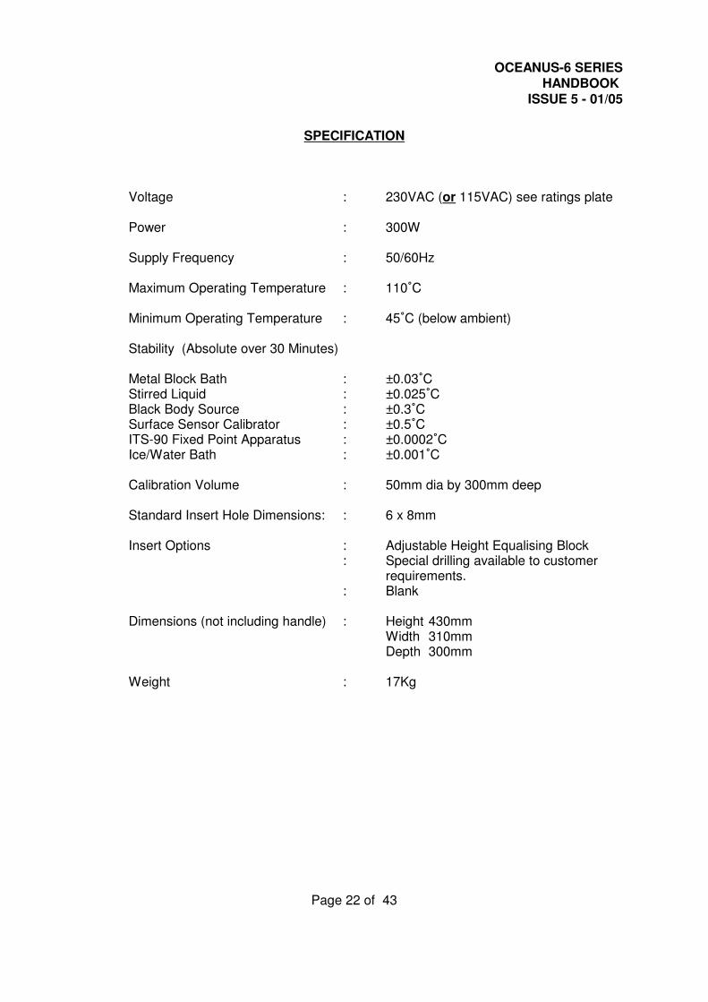
SPECIFICATION
Voltage : 230VAC (or 115VAC) see ratings plate
Power : 300W
Supply Frequency : 50/60Hz
Maximum Operating Temperature : 110/C
Minimum Operating Temperature : 45/C (below ambient)
Stability (Absolute over 30 Minutes)
Metal Block Bath : ±0.03/CStirred Liquid : ±0.025/CBlack Body Source : ±0.3/CSurface Sensor Calibrator : ±0.5/CITS-90 Fixed Point Apparatus : ±0.0002/CIce/Water Bath : ±0.001/C
Calibration Volume : 50mm dia by 300mm deep
Standard Insert Hole Dimensions: : 6 x 8mm
Insert Options : Adjustable Height Equalising Block : Special drilling available to customer
requirements.: Blank
Dimensions (not including handle) : Height 430mmWidth 310mmDepth 300mm
Weight : 17Kg
OCEANUS-6 SERIESHANDBOOK
ISSUE 5 - 01/05
Page 23 of 43
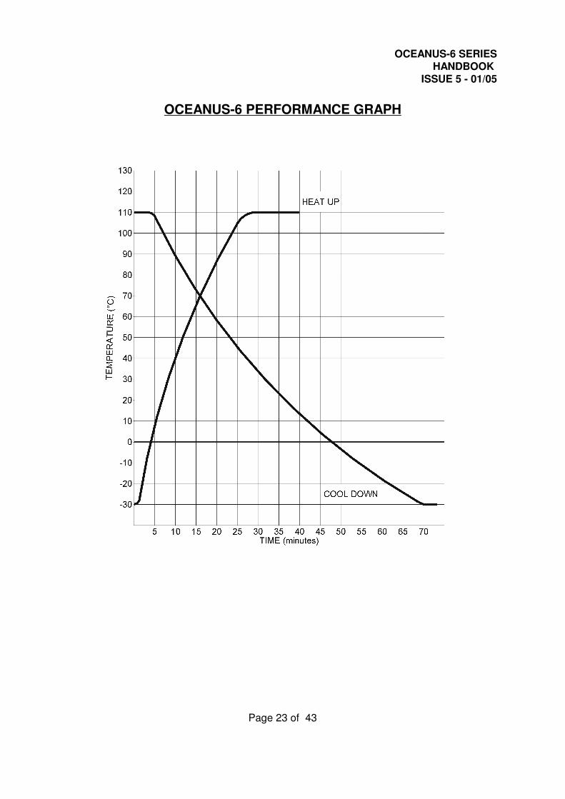
OCEANUS-6 PERFORMANCE GRAPH
OCEANUS-6 SERIESHANDBOOK
ISSUE 5 - 01/05
Page 24 of 43
OPERATING THE OCEANUS-6
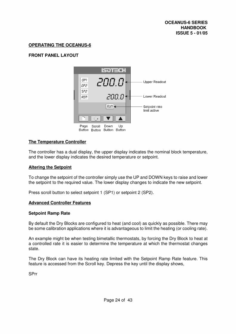
FRONT PANEL LAYOUT
The Temperature Controller
The controller has a dual display, the upper display indicates the nominal block temperature,and the lower display indicates the desired temperature or setpoint.
Altering the Setpoint
To change the setpoint of the controller simply use the UP and DOWN keys to raise and lowerthe setpoint to the required value. The lower display changes to indicate the new setpoint.
Press scroll button to select setpoint 1 (SP1) or setpoint 2 (SP2).
Advanced Controller Features
Setpoint Ramp Rate
By default the Dry Blocks are configured to heat (and cool) as quickly as possible. There maybe some calibration applications where it is advantageous to limit the heating (or cooling rate).
An example might be when testing bimetallic thermostats, by forcing the Dry Block to heat ata controlled rate it is easier to determine the temperature at which the thermostat changesstate.
The Dry Block can have its heating rate limited with the Setpoint Ramp Rate feature. Thisfeature is accessed from the Scroll key. Depress the key until the display shows,
SPrr
OCEANUS-6 SERIESHANDBOOK
ISSUE 5 - 01/05
Page 25 of 43
On the Upper Display, the lower display will show the current value from OFF (default) to 999.9.The desired rate is set here with the UP and DOWN keys, the units are /C/min.
When the SPrr is active the controller display will show "RUN", the lower setpoint display willnow automatically update with the current value, known as the working setpoint. The setpointcan be seen by pressing either the UP and DOWN key.
The Setpoint ramp rate operates when the bath is heating and cooling.
Instrument Address
The controller has a configurable "address" which is used for PC communications. Eachinstrument has an address, this allows several instruments to be connected in parallel on thesame communications bus. The default value is 1. This address would only need to be changedif more than one Dry Block is connected to the same PC port.
To check the Address value press the scroll key until the top display indicates,
Addr
The lower display will show the current value that can be modified with the UP and DOWN keys.
Monitoring the Controller Status
A row of beacons indicate the controllers status as follows,
OP1 Heat OutputOP2 Cool Output (Only for models which operate below 0/C)REM This beacon indicates activity on the PC interface
Units
Momentary pressing the Scroll key will show the controller units /C or /F.
The Temperature Indicator (Not Basic (B) Models)
The site models include an electronic temperature indicator. The indicator can be configuredfor the desired sensor type, and for custom calibration data. The customer calibration data canbe set ON or OFF.
OCEANUS-6 SERIESHANDBOOK
ISSUE 5 - 01/05
Page 26 of 43
Setting the Input Type
A 100 Ohm resistance thermometer can be connected to the PRT Connector or a thermocouplemay be connected to the miniature TC Connector.Ensure that only a PRT or a TC is connected at any one time. If a PRT and TC are
connected simultaneously the indicator will read in error.
Check that any sensor placed into the Oceanus-6 is suitable for the temperature range.Sensors can be damaged if taken outside their normal operating limits.
The desired sensor type is easily set, press the Scroll key until the upper display indicates,
inPt
On the upper display. The lower display will show the current set sensor type,
J.tc J thermocoupleK.tc K thermocouple L.tc L thermocoupler.tc R thermocouple (Pt/Pt13%Rh)b.tc B thermocouple (Pt30%Rh/Pt6%Rh)n.tc N thermocouplet.tc T thermocoupleS.tc S thermocouple (Pt/Pt10%Rh)PL.2 PL 2 thermocouplertd 100S platinum resistance thermometer.T012 E thermocouple
Again the value can be modified with the UP and DOWN keys.
Enabling / Disabling Custom Calibration
Custom calibration allows the indicator to be programmed to suit a particular temperaturesensor. This allows the indicator to automatically show the true temperature, without having tomanually apply a correction.
When the Custom or User Calibration is active the indicator will show the REM beacon litcontinuously. The use of User calibration can make a significant difference to the accuracy ofthe instrument, and this REM beacon provides a clear and continuous indication of thecalibration status. Isotech will configure and set user calibration when the Dry Block is orderedwith a temperature sensor.
OCEANUS-6 SERIESHANDBOOK
ISSUE 5 - 01/05
Page 27 of 43
To alter the calibration status press the Scroll key until the upper display shows,
CALThe lower display will indicate either,USEr for user calibration
OrFACt for factory calibration of the indicator, i.e. User Cal OFF
Use the UP and DOWN keys to toggle between the two values.
When calibrating an unknown sensor against a calibrated probe it may be necessary to switchthe calibration off for the unknown, and on for the calibrated probe.
Instrument Address
Like the controller, the indicator has a configurable "address" which is used for PCcommunications. Each instrument has an address; this allows several instruments to beconnected in parallel on the same communications bus. The default value is 2 (The controllerdefaults to 1). This address would only need to be changed if more than one Dry Block isconnected to the same PC port.
To check the Address value press the scroll key until the top display indicates,
Addr
The lower display will show the current value that can be modified with the UP and DOWN keys.
Monitoring the Indicator Status
For the indicator the REM beacon is lit continuously when the user calibration is active, the REMbeacon flashes when the PC communications port is active.
Units
Momentary pressing the Scroll key will show the controller units /C or /F.
Advanced Indicator Operation
The indicator can be configured with up to five custom calibration points; the points contain"data pairs". First the temperature (point) and secondly the Error (offset) at this temperaturepoint. Isotech Dry Block calibration certificates will show the values to suit a particular sensor.
These values can be inspected, and modified with the following procedure,
OCEANUS-6 SERIESHANDBOOK
ISSUE 5 - 01/05
Page 28 of 43
Press the PAGE key until the display indicates,
ACCSLiSt
Press the SCROLL key until the display shows,
GotoOPEr
Press the UP key until the display shows
GotoconF
Press the Scroll Key twice, when the display will show,
inStConf
Press the Page Key until the controller shows
CALConf
Now use the Scroll key to examine the data pairs. The values can be modified with the UP andDOWN keys.
To exit this mode press the Page key until the top display shows,
Exit
And then set the lower display to YES. While in this mode take care not to modify otherparameters - a full list of all the parameters can be found in appendix 2.
OCEANUS-6 SERIESHANDBOOK
ISSUE 5 - 01/05
Page 29 of 43
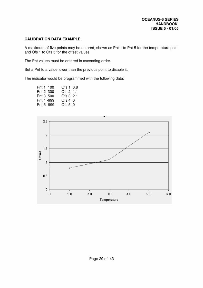
CALIBRATION DATA EXAMPLE
A maximum of five points may be entered, shown as Pnt 1 to Pnt 5 for the temperature pointand Ofs 1 to Ofs 5 for the offset values.
The Pnt values must be entered in ascending order.
Set a Pnt to a value lower than the previous point to disable it.
The indicator would be programmed with the following data:
Pnt 1 100 Ofs 1 0.8Pnt 2 300 Ofs 2 1.1Pnt 3 500 Ofs 3 2.1Pnt 4 -999 Ofs 4 0Pnt 5 -999 Ofs 5 0
OCEANUS-6 SERIESHANDBOOK
ISSUE 5 - 01/05
Page 30 of 43
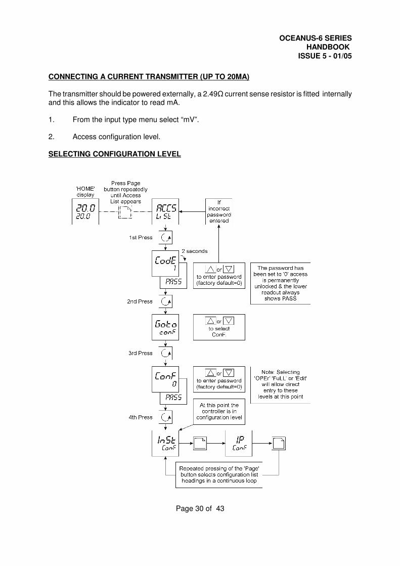
CONNECTING A CURRENT TRANSMITTER (UP TO 20MA)
The transmitter should be powered externally, a 2.49S current sense resistor is fitted internallyand this allows the indicator to read mA.
1. From the input type menu select “mV”.
2. Access configuration level.
SELECTING CONFIGURATION LEVEL
OCEANUS-6 SERIESHANDBOOK
ISSUE 5 - 01/05
Page 31 of 43
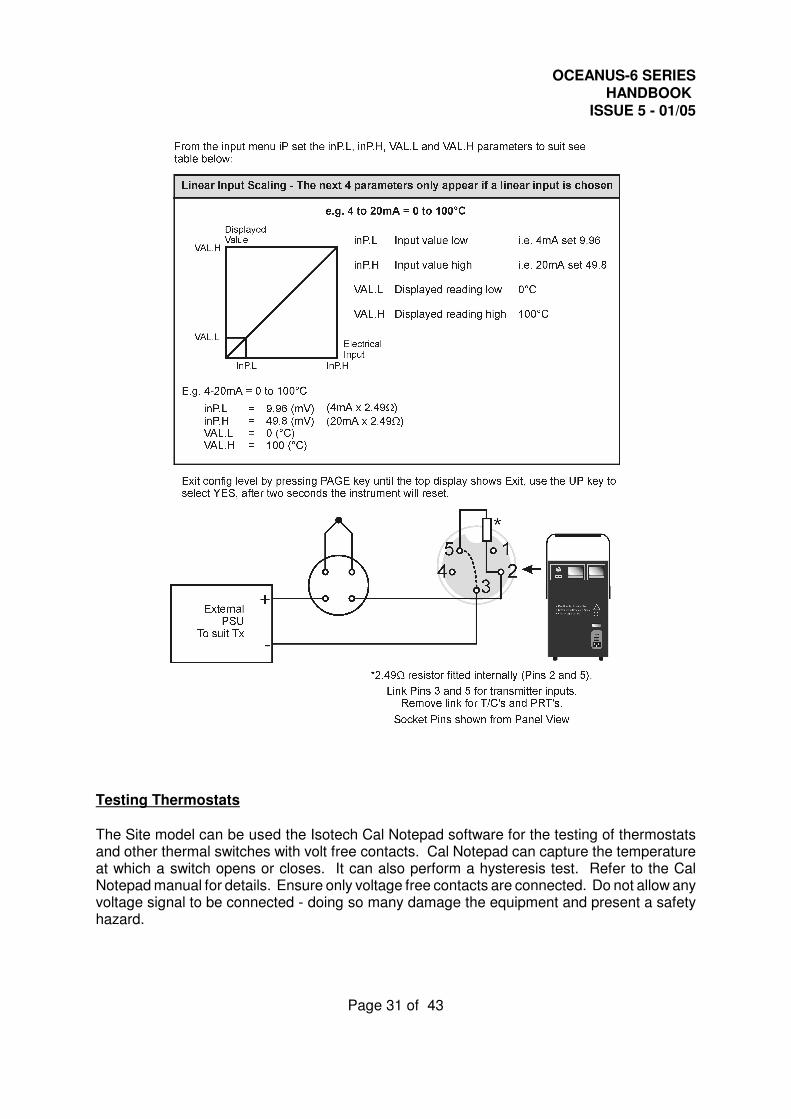
Testing Thermostats
The Site model can be used the Isotech Cal Notepad software for the testing of thermostatsand other thermal switches with volt free contacts. Cal Notepad can capture the temperatureat which a switch opens or closes. It can also perform a hysteresis test. Refer to the CalNotepad manual for details. Ensure only voltage free contacts are connected. Do not allow anyvoltage signal to be connected - doing so many damage the equipment and present a safetyhazard.
OCEANUS-6 SERIESHANDBOOK
ISSUE 5 - 01/05
Page 32 of 43
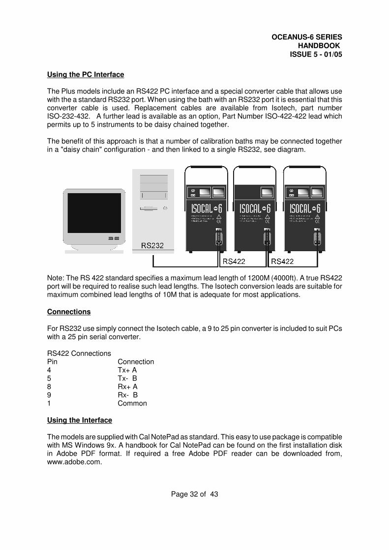
Using the PC Interface
The Plus models include an RS422 PC interface and a special converter cable that allows usewith the a standard RS232 port. When using the bath with an RS232 port it is essential that thisconverter cable is used. Replacement cables are available from Isotech, part numberISO-232-432. A further lead is available as an option, Part Number ISO-422-422 lead whichpermits up to 5 instruments to be daisy chained together.
The benefit of this approach is that a number of calibration baths may be connected togetherin a "daisy chain" configuration - and then linked to a single RS232, see diagram.
Note: The RS 422 standard specifies a maximum lead length of 1200M (4000ft). A true RS422port will be required to realise such lead lengths. The Isotech conversion leads are suitable formaximum combined lead lengths of 10M that is adequate for most applications.
Connections
For RS232 use simply connect the Isotech cable, a 9 to 25 pin converter is included to suit PCswith a 25 pin serial converter.
RS422 ConnectionsPin Connection4 Tx+ A5 Tx- B8 Rx+ A9 Rx- B1 Common
Using the Interface
The models are supplied with Cal NotePad as standard. This easy to use package is compatiblewith MS Windows 9x. A handbook for Cal NotePad can be found on the first installation diskin Adobe PDF format. If required a free Adobe PDF reader can be downloaded from,www.adobe.com.
OCEANUS-6 SERIESHANDBOOK
ISSUE 5 - 01/05
Page 33 of 43
CAL NOTEPAD
Cal Notepad can be used to log and display values from the Dry Blocks and an optionaltemperature indicator.
Minimum System Requirements
CNP requires Windows 95 / 98, a minimum of 5Mb of free hard drive space and free serial portsfor the instruments to be connected.
Development
CNP was developed by Isothermal Technology using LabVIEW from National Instruments.
License
Use of the Cal NotePad software program "CNP" is as granted in this license agreement. Inusing the CNPsoftware the user "licensee" is agreeing to the terms of the license. You must read andunderstand the terms of this license before using CNP.1, This license permits licensee to use CNP software on a single computer. The user may makecopies for back up and archival purposes freely as long as the software is only ever in use ona single computer at any one time. Please enquire about multi-user licenses.2, CNP is protected by international copyright laws and treaties. CNP must not be distributedto third parties.3, CNP must not be reversed engineered, disassembled or de-compiled. Licensee may transferthe software to a third party provided that no copies or upgrades of CNP are retained.4, It is the responsibility of the user to ensure the validity of all stored results and printedcertificates. Isothermal Technology Ltd accept no responsibility for any errors caused byinappropriate use, incorrect set up or any other cause; including defects in the software.5, Limited Warranty. Isothermal Technology warrants that CNP will perform substantially asdescribed in this manual for a period of 90 days from receipt. Any distribution media will undernormal used be guaranteed for a period of 90 days.
NO OTHER WARRANTIES, EXCEPT AS STATED ABOVE. The software and documentationis provided "as is" without warranty of any kind and no other warranties (either expressed orimplied) are made with regard to CNP. Isothermal Technology does not warrant, guarantee ormake any representations regarding the use or results of the use of the software ordocumentation and does not warrant that the operation of CNP will be error free.
In no event will Isothermal Technology, its employees, agents or other associated people beliable for direct, indirect, incidental or consequential damages, expenses, lost profits, businessinterruption, lost business information or other damages arising out the use or inability to useCNP. The license fee reflects this allocation of risk.
CNP is not designed for situations where the results can threaten or cause injury to humans.
OCEANUS-6 SERIESHANDBOOK
ISSUE 5 - 01/05
Page 34 of 43
Installing Cal NotePad
1 Insert CNP DISK 1 into the disk drive2 Click on the START button on the task bar, select RUN, type A:\SETUP (Where A: is
your drive letter) then click OK3. Follow the prompts which will install the application and necessary LabVIEW run time
support files.4 Should you ever need to uninstall the software then use the Add/Remove Programs
option from the Control Panel.
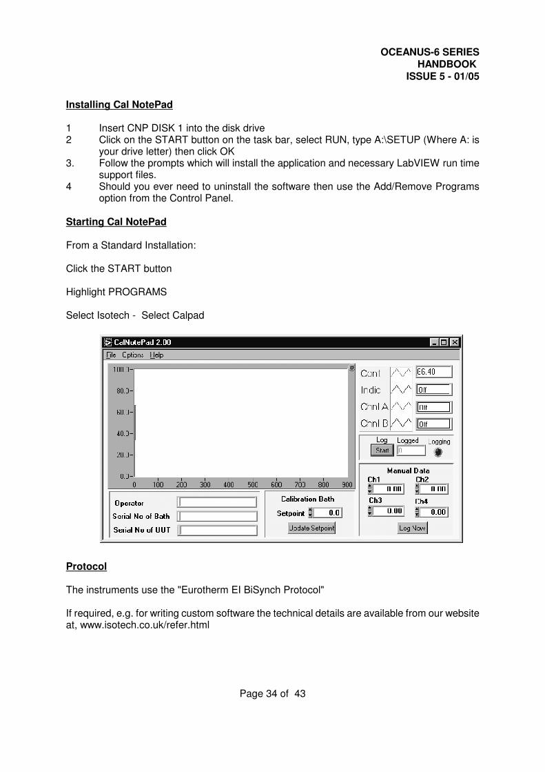
Starting Cal NotePad
From a Standard Installation:
Click the START button Highlight PROGRAMS
Select Isotech - Select Calpad
Protocol
The instruments use the "Eurotherm EI BiSynch Protocol"
If required, e.g. for writing custom software the technical details are available from our websiteat, www.isotech.co.uk/refer.html
OCEANUS-6 SERIESHANDBOOK
ISSUE 5 - 01/05
Page 35 of 43
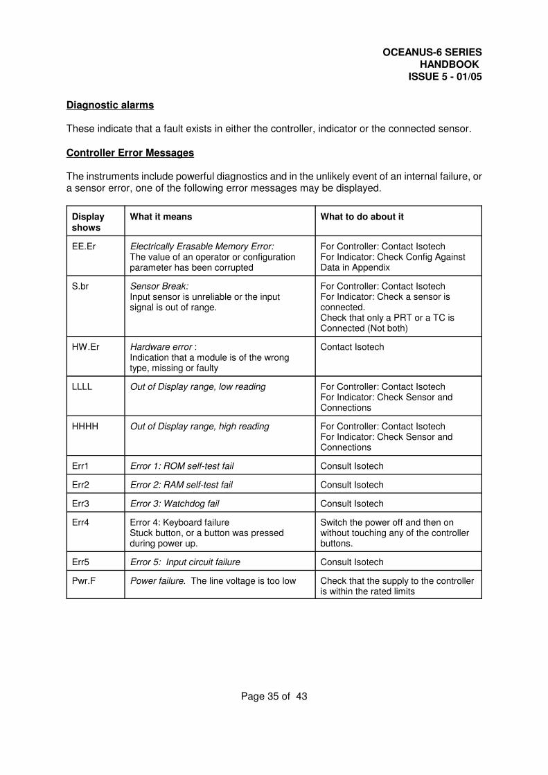
Diagnostic alarms
These indicate that a fault exists in either the controller, indicator or the connected sensor.
Controller Error Messages
The instruments include powerful diagnostics and in the unlikely event of an internal failure, ora sensor error, one of the following error messages may be displayed.
Display shows
What it means What to do about it
EE.Er Electrically Erasable Memory Error:The value of an operator or configurationparameter has been corrupted
For Controller: Contact Isotech For Indicator: Check Config AgainstData in Appendix
S.br Sensor Break:Input sensor is unreliable or the input signal is out of range.
For Controller: Contact Isotech For Indicator: Check a sensor isconnected.Check that only a PRT or a TC isConnected (Not both)
HW.Er Hardware error :Indication that a module is of the wrong type, missing or faulty
Contact Isotech
LLLL Out of Display range, low reading For Controller: Contact Isotech For Indicator: Check Sensor andConnections
HHHH Out of Display range, high reading For Controller: Contact Isotech For Indicator: Check Sensor andConnections
Err1 Error 1: ROM self-test fail Consult Isotech
Err2 Error 2: RAM self-test fail Consult Isotech
Err3 Error 3: Watchdog fail Consult Isotech
Err4 Error 4: Keyboard failure Stuck button, or a button was pressedduring power up.
Switch the power off and then onwithout touching any of the controllerbuttons.
Err5 Error 5: Input circuit failure Consult Isotech
Pwr.F Power failure. The line voltage is too low Check that the supply to the controlleris within the rated limits
OCEANUS-6 SERIESHANDBOOK
ISSUE 5 - 01/05
Page 36 of 43
INITIAL TESTING
This unit was fully tested before despatch to you but please check its operation as outlinedbelow.
After connecting the Oceanus-6 to the electricity supply, the temperature controller display willshow the temperature of the block and the last set-point value. The controller and indicatorboth go through a self-test sequence first.
Change the set-point to 50°C and observe that the block temperature rises and settles to thisvalue. Place a thermometer in the insert in the block and connect it to the suitably configuredindicator. Confirm that the indicator agrees within ±2°C of the controller.
Your unit should have performed as described above and can now be used for calibration.
If any problems or faults arise during these tests please contact us or our agents for help andadvice.
IMPORTANT NOTICE
The controller's function settings are preset and will not require adjustment.
The Oceanus-6 uses a powerful fan to cool the heat sinks inside the unit. This fan is locatedunder the block assembly and should under no circumstances, be restricted. Restriction of thisfan will impair the performance of the unit.
The Oceanus-6 uses Solid State Heat Pumps to drive the temperature range. These pumpsto drive the temperature range. These pumps are very fragile and should be considered whenlowering heavy objects into the well.

OCEANUS-6 SERIESHANDBOOK
ISSUE 5 - 01/05
Page 37 of 43
MAINTENANCE
Maintenance is limit to keeping the apparatus and the calibration volume clean and free fromdebris.
There are no internal user serviceable parts.
Repair and maintenance must be carried out by Isothermal Technology Limited or an approvedagent.
OCEANUS-6 SERIESHANDBOOK
ISSUE 5 - 01/05
Page 38 of 43
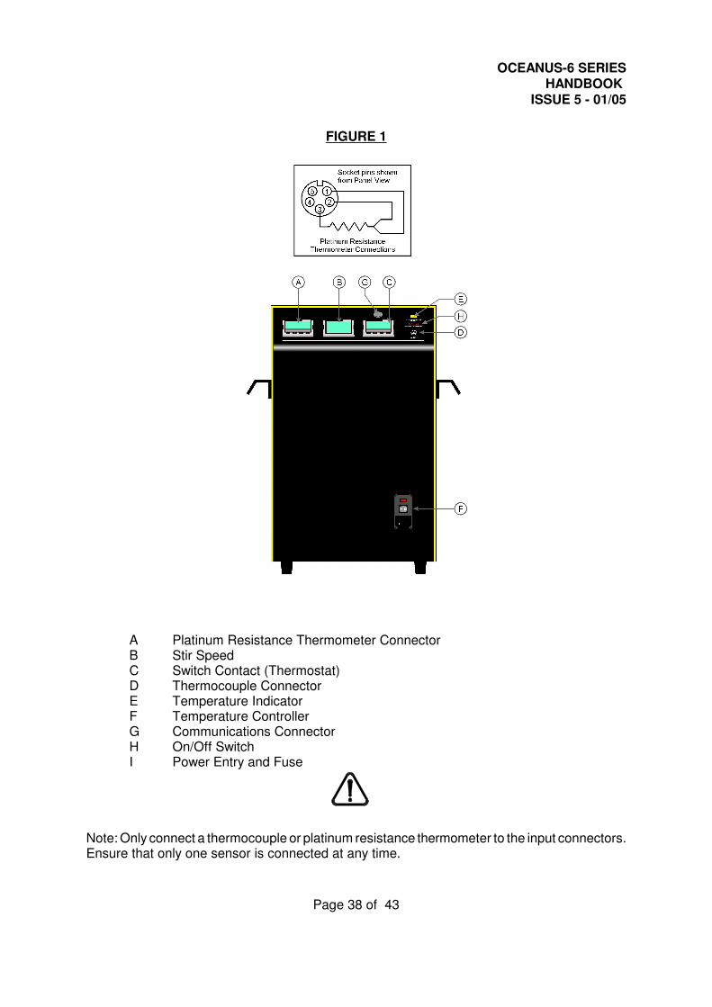
FIGURE 1
A Platinum Resistance Thermometer ConnectorB Stir SpeedC Switch Contact (Thermostat)D Thermocouple ConnectorE Temperature IndicatorF Temperature ControllerG Communications ConnectorH On/Off SwitchI Power Entry and Fuse
Note: Only connect a thermocouple or platinum resistance thermometer to the input connectors.Ensure that only one sensor is connected at any time.
OCEANUS-6 SERIESHANDBOOK
ISSUE 5 - 01/05
Page 39 of 43
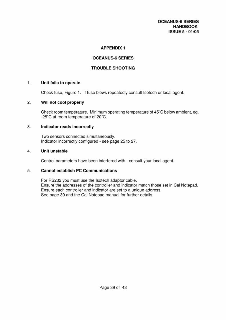
APPENDIX 1
OCEANUS-6 SERIES
TROUBLE SHOOTING
1. Unit fails to operate
Check fuse, Figure 1. If fuse blows repeatedly consult Isotech or local agent.
2. Will not cool properly
Check room temperature. Minimum operating temperature of 45/C below ambient, eg.-25/C at room temperature of 20/C.
3. Indicator reads incorrectly
Two sensors connected simultaneously.Indicator incorrectly configured - see page 25 to 27.
4. Unit unstable
Control parameters have been interfered with - consult your local agent.
5. Cannot establish PC Communications
For RS232 you must use the Isotech adaptor cable.Ensure the addresses of the controller and indicator match those set in Cal Notepad.Ensure each controller and indicator are set to a unique address.See page 30 and the Cal Notepad manual for further details.
OCEANUS-6 SERIESHANDBOOK
ISSUE 5 - 01/05
Page 40 of 43
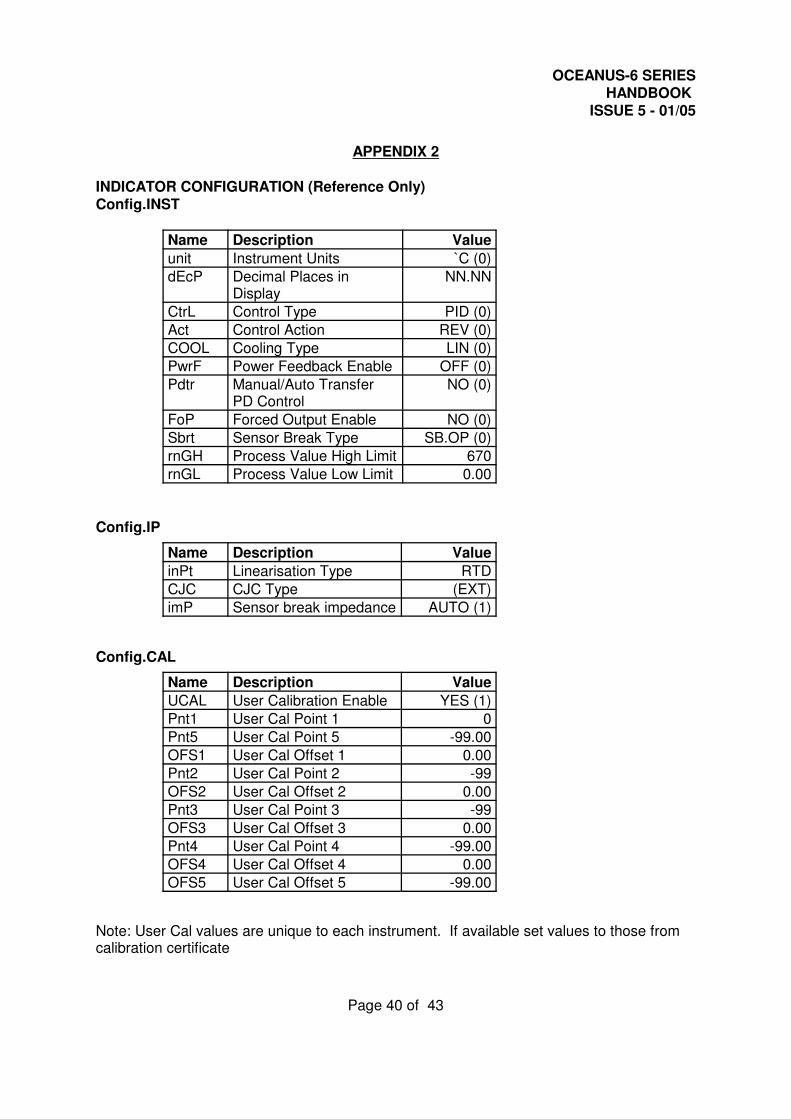
APPENDIX 2
INDICATOR CONFIGURATION (Reference Only)Config.INST
Name Description Value
unit Instrument Units `C (0)
dEcP Decimal Places inDisplay
NN.NN
CtrL Control Type PID (0)
Act Control Action REV (0)
COOL Cooling Type LIN (0)
PwrF Power Feedback Enable OFF (0)
Pdtr Manual/Auto TransferPD Control
NO (0)
FoP Forced Output Enable NO (0)
Sbrt Sensor Break Type SB.OP (0)
rnGH Process Value High Limit 670
rnGL Process Value Low Limit 0.00
Config.IP
Name Description Value
inPt Linearisation Type RTD
CJC CJC Type (EXT)
imP Sensor break impedance AUTO (1)
Config.CAL
Name Description Value
UCAL User Calibration Enable YES (1)
Pnt1 User Cal Point 1 0
Pnt5 User Cal Point 5 -99.00
OFS1 User Cal Offset 1 0.00
Pnt2 User Cal Point 2 -99
OFS2 User Cal Offset 2 0.00
Pnt3 User Cal Point 3 -99
OFS3 User Cal Offset 3 0.00
Pnt4 User Cal Point 4 -99.00
OFS4 User Cal Offset 4 0.00
OFS5 User Cal Offset 5 -99.00
Note: User Cal values are unique to each instrument. If available set values to those fromcalibration certificate
OCEANUS-6 SERIESHANDBOOK
ISSUE 5 - 01/05
Page 41 of 43
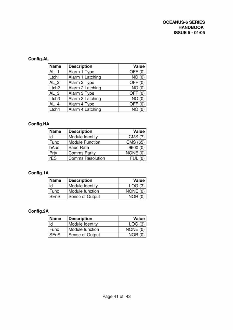
Config.AL
Name Description Value
AL_1 Alarm 1 Type OFF (0)
Ltch1 Alarm 1 Latching NO (0)
AL_2 Alarm 2 Type OFF (0)
Ltch2 Alarm 2 Latching NO (0)
AL_3 Alarm 3 Type OFF (0)
Ltch3 Alarm 3 Latching NO (0)
AL_4 Alarm 4 Type OFF (0)
Ltch4 Alarm 4 Latching NO (0)
Config.HA
Name Description Value
id Module Identity CMS (7)
Func Module Function CMS (65)
bAud Baud Rate 9600 (0)
Prty Comms Parity NONE (0)
rES Comms Resolution FUL (0)
Config.1A
Name Description Value
id Module Identity LOG (3)
Func Module function NONE (0)
SEnS Sense of Output NOR (0)
Config.2A
Name Description Value
id Module Identity LOG (3)
Func Module function NONE (0)
SEnS Sense of Output NOR (0)
OCEANUS-6 SERIESHANDBOOK
ISSUE 5 - 01/05
Page 42 of 43
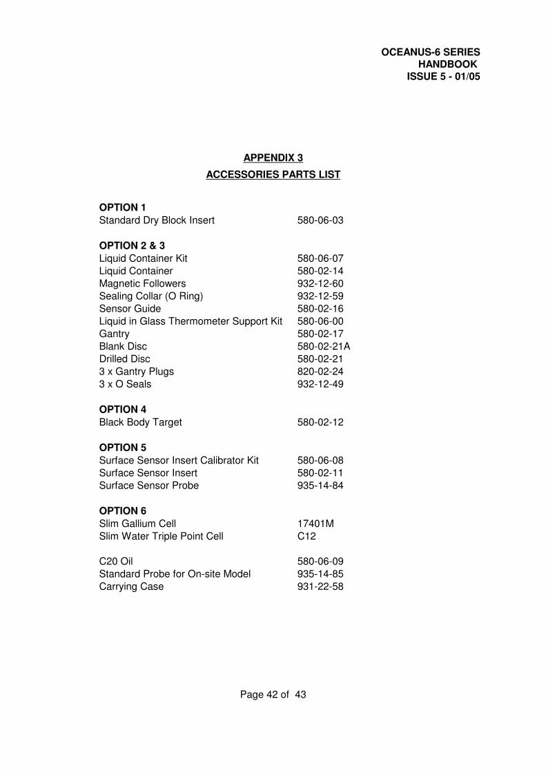
APPENDIX 3
ACCESSORIES PARTS LIST
OPTION 1
Standard Dry Block Insert 580-06-03
OPTION 2 & 3
Liquid Container Kit 580-06-07
Liquid Container 580-02-14
Magnetic Followers 932-12-60
Sealing Collar (O Ring) 932-12-59
Sensor Guide 580-02-16
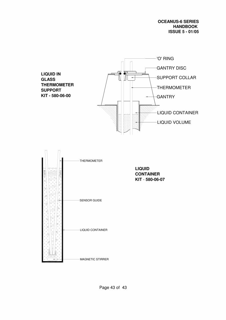
Liquid in Glass Thermometer Support Kit 580-06-00
Gantry 580-02-17
Blank Disc 580-02-21A
Drilled Disc 580-02-21
3 x Gantry Plugs 820-02-24
3 x O Seals 932-12-49
OPTION 4
Black Body Target 580-02-12
OPTION 5
Surface Sensor Insert Calibrator Kit 580-06-08
Surface Sensor Insert 580-02-11
Surface Sensor Probe 935-14-84
OPTION 6
Slim Gallium Cell 17401M
Slim Water Triple Point Cell C12
C20 Oil 580-06-09
Standard Probe for On-site Model 935-14-85
Carrying Case 931-22-58
OCEANUS-6 SERIESHANDBOOK
ISSUE 5 - 01/05
Page 43 of 43
GANTRY DISC
SUPPORT COLLAR
THERMOMETER
GANTRY
LIQUID CONTAINER
LIQUID VOLUME
'O' RING
THERMOMETER
SENSOR GUIDE
LIQUID CONTAINER
MAGNETIC STIRRER
LIQUID IN
GLASS
THERMOMETER
SUPPORT
KIT - 580-06-00
LIQUID
CONTAINER
KIT - 580-06-07