Embed Size (px)
Citation preview

STUDENT MANUAL
Occupational/Industrial Hygiene in
the Mining and Mineral Processing
Industries
December 2019
This course is offered by the Occupational Hygiene Training Association and available free of charge
though the OHTA website Ohtatraining.org.
Copyright information
This student manual is provided under the Creative Commons Attribution - NoDerivs licence agreement.
It can only be reproduced in its entirety without change, unless with the prior written permission of OHTA.
Occupational Hygiene Training Association, 5/6 Melbourne Business Court
Millennium Way, Pride Park, Derby, DE24 8LZ
Email: [email protected]

CONTENTS
ACKNOWLEDGEMENTS ................................................................................................. i
ABBREVIATIONS ............................................................................................................ ii
1. COURSE OVERVIEW .............................................................................................. 1
1.1 Introduction ......................................................................................................... 1
1.2 Aim of course ..................................................................................................... 1
1.3 Learning outcomes ............................................................................................. 1
1.4 Format of manual ............................................................................................... 2
2. OVERVIEW OF THE MINING AND MINERAL PROCESSING INDUSTRY ............. 3
2.1 A brief history of mining ...................................................................................... 3
2.2 Imperative for management of occupational health ............................................ 5
2.3 Open pit operations ............................................................................................ 7
2.4 Underground mining ........................................................................................... 7
2.5 Mineral processing ........................................................................................... 10
2.5.1 Sizing processes ........................................................................................ 10
2.5.2 Hydrometallurgy processes ....................................................................... 11
2.5.3 Molten salt processes ................................................................................ 13
2.5.4 Pyrometallurgical processes ...................................................................... 14
3. ROLE OF THE HYGIENIST IN THE MINING INDUSTRY ..................................... 16
3.1 Functions of hygienists in the HSE team .......................................................... 16
3.2 Integration of hygiene into the HSE function .................................................... 18
3.3 Emergency response ........................................................................................ 19
3.4 Addressing occupational hygiene issues .......................................................... 19
3.4.1 Introduction ................................................................................................ 19
3.4.2 Immediate issues ....................................................................................... 20

3.4.3 A structured approach ................................................................................ 22
3.4.4 Example: The International Council on Mining & Metals (ICMM) approach ......... 27
4. BASIC OCCUPATIONAL HYGIENE PROGRAMMES ........................................... 31
4.1 Hazard communication – SDS systems, chemical inventories, training ........... 31
4.2 Hearing conservation ........................................................................................ 32
4.3 Dust / respiratory protection ............................................................................. 34
4.4 Ergonomics ...................................................................................................... 39
4.5 Confined spaces ............................................................................................... 43
4.6 Radiation protection.......................................................................................... 49
4.7 Asbestos management ..................................................................................... 50
4.8 Thermal environment ........................................................................................ 53
4.9 Legionella management ................................................................................... 55
4.10 Welding and other processes ........................................................................ 56
4.11 Personal protective equipment (PPE) ........................................................... 60
4.11.1 Respirators ............................................................................................. 60
4.11.2 Personal hearing protection .................................................................... 67
4.11.3 Eye protection ......................................................................................... 70
4.11.4 Gloves .................................................................................................... 71
4.12 Potable water ................................................................................................ 72
4.13 Food safety .................................................................................................. 74
4.14 Alcohol and drugs ......................................................................................... 75
4.15 Fatigue .......................................................................................................... 77
4.16 Vector borne and infectious diseases ................................................................ 79
4.16.1 Malaria ......................................................................................................... 79
4.17 Health surveillance ........................................................................................ 82
5. SPECIFIC ISSUES ASSOCIATED WITH MINING ................................................. 85
5.1 Ventilation ......................................................................................................... 85
5.1.1 Introduction ................................................................................................ 85

5.1.2 Ventilation design principles – non-coal mines .......................................... 85
5.1.3 Ventilation design principles – coal mines ................................................. 92
5.1.4 Summary ................................................................................................... 97
5.2 Noise ................................................................................................................ 98
5.2.1 Introduction ................................................................................................ 98
5.2.2 Health effects ........................................................................................... 101
5.2.3 Typical mining industry related noise levels ............................................. 104
5.2.4 Very high and impact noise ...................................................................... 105
5.3 Volatile organic vapours ................................................................................. 107
5.3.1 Introduction .............................................................................................. 107
5.3.2 Health effects ........................................................................................... 108
5.3.3 Exposure levels ........................................................................................ 110
5.3.4 Typical constituents of splicing compounds ............................................. 110
5.4 Vibration (whole body & hand arm) ................................................................ 112
5.4.1 Health effects ........................................................................................... 113
5.4.2 Control of vibration ................................................................................... 116
5.5 Spontaneous combustion ............................................................................... 118
5.6 Hazards of overburden removal ..................................................................... 120
5.7 Diesel emissions............................................................................................. 121
5.7.1 Introduction .............................................................................................. 121
5.7.2 Composition of diesel exhaust fumes ...................................................... 121
5.7.3 Health effects of diesel particulate (DP) ................................................... 123
5.7.4 Control of emissions ................................................................................ 125
5.8 NORM in ores ................................................................................................. 125
5.8.1 Background .............................................................................................. 125
5.8.2 Radiation protection series ...................................................................... 127
5.8.3 Summary of safety guide for NORM (ARPANSA 2008) ........................... 128
5.9 Intrinsic safety of equipment ........................................................................... 130

5.9.1 Introduction .............................................................................................. 130
5.9.2 International Electrotechnical Commission scheme ................................. 130
5.9.3 Explosion protection ................................................................................. 131
5.9.4 Levels of protection and zones of application .......................................... 134
5.9.5 The Ex marking label ............................................................................... 135
5.10 Tunnelling .................................................................................................... 136
5.10.1 Introduction ........................................................................................... 136
5.10.2 Respirable quartz ................................................................................. 137
5.10.3 Typical tunnelling operations ................................................................ 137
5.11 Silicosis ....................................................................................................... 138
6. SPECIFIC ISSUES ASSOCIATED WITH MINERAL PROCESSING ................... 141
6.1 Introduction ..................................................................................................... 141
6.2 Hazards from mineral processing ................................................................... 142
6.3 Beneficiation of hazards ................................................................................. 142
6.4 Specific metals and minerals .......................................................................... 144
6.4.1 Aluminium ................................................................................................ 144
6.4.2 Lead / Zinc ............................................................................................... 148
6.4.3 Gold ......................................................................................................... 150
6.4.4 Copper ..................................................................................................... 153
6.4.5 Nickel ....................................................................................................... 155
6.4.6 Coal mining .............................................................................................. 156
6.5 Acid and other processing chemical mists ...................................................... 158
6.6 Fixed radiation gauges ................................................................................... 159
6.6.1 Introduction .............................................................................................. 159
6.6.2 Safe use of fixed radiation gauges ........................................................... 160
6.6.3 Dose limits ............................................................................................... 162
6.6.4 Additional reference documents............................................................... 163
7. EXPOSURE ASSESSMENT ................................................................................ 166

7.1 Introduction ..................................................................................................... 166
7.2 Getting to know the sites ................................................................................ 166
7.2.1 Initial hygiene survey & basic characterisation ........................................ 167
7.2.2 Exposure assessment monitoring follow-up ............................................. 171
7.3 Exposure assessment .................................................................................... 172
7.3.1 Identification of similar exposure groups (SEGs) ..................................... 175
7.3.2 Exposure profile / statistical analysis ....................................................... 177
7.3.3 Acceptability of the exposure profile ........................................................ 183
7.3.4 Biological exposure monitoring ................................................................ 185
7.4 Continuous improvement cycle ...................................................................... 186
7.5 Reporting results ............................................................................................ 186
7.6 Application of control strategies ...................................................................... 188
7.7 Development of effective control programmes ............................................... 188
8. REFERENCES ..................................................................................................... 191
i.
ACKNOWLEDGEMENTS This manual was originally developed by Associate Professor Brian Davies and
Mr John Henderson of the School of Health Sciences at the University of Wollongong,
Australia. It has most recently been revised by Ross Di Corleto, Ian Firth and Tim White.
In the development of this manual considerable assistance has been received and the
authors would like to express their appreciation to the University of Wollongong, Australia
as well as the following organisations and individuals for their support or contribution.
It should be noted that a considerable proportion of the content of this manual has been
reproduced from the publications “Keeping Coal Miners Healthy at Work” published by
Coal Services Health & Safety Trust and “Principles of Occupational Health & Hygiene”
published by the Australian Institute of Occupational Hygienists (AIOH). In both cases
copyright of the material is retained by each organisation and permission to use the
material has been granted to the authors, for which the authors are extremely grateful.
Andrew Rowe
Australian Institute of Occupational Hygienists
Coal Services Health & Safety Trust
Gavin Irving
Gerard Tiernan
Ken Cram
Kevin Hedges
Version Release Date Comments
I.0 December 2019 Initial version
Supported by
This work is licensed under a
Creative Commons Attribution-
No Derivative

ii.
ABBREVIATIONS
µm ....................... Micrometre
ACGIH ................. American Conference of Governmental Industrial Hygienists
AIOH .................... Australian Institute of Occupational Hygienists
ARPANSA ........... Australian Radiation Protection and Nuclear Safety Agency
AS/NZS................ Australian and New Zealand Standard
CDC ..................... Centres for Disease Control and Prevention
c/t ......................... cut through
dB ........................ Decibel
DP ....................... Diesel Particulate
EC ....................... Elemental Carbon
EPA ..................... Environmental Protection Agency
GM ....................... Geometric Mean
GSD ..................... Geometric Standard Deviation
H2S ...................... Hydrogen Sulphide
HRA ..................... Health Risk Assessment
HSE ..................... Health, Safety & Environmental
Hz ........................ Hertz
IAEA .................... International Atomic Energy Agency
IARC .................... International Agency for Research on Cancer
ICMM ................... International Council on Mining & Metals
ICRP .................... International Commission on Radiation Protection
IECEx .................. International Electrotechnical Commission Scheme
ILO ....................... International Labour Organisation
IS ......................... Intrinsic Safety
ISO ...................... International Organisation for Standardisation
LEL ...................... Lower Explosive Limit
iii.
LHD ..................... Load Haul Dump
MEK ..................... Methyl Ethyl Ketone
MVUE .................. Minimum Variance Unbiased Estimate
NIHL .................... Noise Induced Hearing Loss
NIOSH ................. National Institute of Occupational Safety and Health
NORM ................. Naturally Occurring Radioactive Material
OEL ..................... Occupational Exposure Limit
OH&S .................. Occupational Health & Safety
OSHA .................. Occupational Safety and Health Administration
PAH ..................... Polycyclic Aromatic Hydrocarbons
PPE ..................... Personal Protective Equipment
ppm ..................... parts per million
PVC ..................... Poly Vinyl Chloride
ROM .................... Run of mine
SAG ..................... Semi autogenous grinding
SDS ..................... Safety Data Sheet
SEGs ................... Similar Exposure Groups
SPL ...................... Sound Pressure Level
SX ........................ Solvent extraction
TLV ...................... Threshold Limit Value
TWA .................... Time Weighted Average
UCL ..................... Upper Confidence Limit
UK ....................... United Kingdom
WBV .................... Whole Body Vibration
WHO .................... World Health Organization
1.
1. COURSE OVERVIEW 1.1 Introduction
Students undertaking this subject should have completed the following
pre-requisite subjects or equivalent:
• Measurement of Hazardous Substances (W501)
• Control of Hazardous Substances (W505)
• Thermal Environment (W502)
• Health Effects of Hazardous Substances (W507)
While not a pre-requisite, it would also be helpful if the subject “Noise –
Measurement and Its Effects” (W503) had been completed.
This Student Manual builds on the learnings provided in these topics and
focuses on the application of the principles of occupational hygiene in the
specific environment of the mining industry.
1.2 Aim of course
The aim of this subject is to provide the student with specialist information
relating to workplace situations likely to arise in the mining industry. Specific
information will be provided as to potential occupational hygiene risks in mining
and mineral processing, their identification, evaluation and control.
1.3 Learning outcomes On completion of this subject, students should be able to:
a) Apply the skills obtained in the core subjects to situations specific to the
mining and mineral processing industry.
b) Outline the key occupational hygiene issues within the mining and
mineral processing industry and describe how to manage these issues.
c) Understand how to assess workplaces in the mining and mineral
processing industry for potential unacceptable exposures.

2.
d) Prepare reports on workplace assessments suitable for communication
to all stakeholders.
1.4 Format of manual
The material provided in this manual has been loosely aligned with the
presentations for each topic.
It should be recognised that the format presented in this manual represents
the views of the authors and does not imply any mandatory process or format
that must be rigidly observed. Presenters using this manual may well choose
to alter the teaching sequence or course material to suit their requirements. In
this regard, any case studies are provided as illustrative examples only and
alternate case studies relevant to a particular mining activity or process may
be used if desired.
In the final outcome, the aim of this manual is to transmit the principles of
occupational hygiene and provide guidance as to how those principles should
be applied to the mining and mineral processing industry.

3.
2. OVERVIEW OF THE MINING AND MINERAL PROCESSING INDUSTRY
Mining is defined in the Macquarie Dictionary as the action, process, or
industry of extracting ores and other materials from mines. This subject looks
at the various types of mines, equipment likely to be encountered, mineral
processing and metal refining activities, and the associated hazards. Hazards
intrinsic to the environment are also considered.
Mines may be relatively small quarries to large open pit operations; from small
shaft, single worker opal mines to large underground mines with hundreds and
maybe thousands of workers. Most of the hazards faced and many of the
machines used are common to all types of mining; only the scale changes.
2.1 A brief history of mining
For many centuries, the influence of the workplace environment on the health
of workers has been recognised and sometimes investigated. History records
that Hippocrates in the 4th century BC recognised the toxicity of lead, although
little was done to protect workers because, being mainly slaves, they were
regarded as expendable. Pliny the Elder, a Roman of note in the 1st century
AD, described a protective mask, made from an animal bladder, which was
used by workers in dusty trades.
In terms of the mining industry, Ulrich Ellenborg in 1473 produced the first
publication on occupational disease and injury amongst gold miners. He was
the first to offer instruction in hygiene and other preventative measures.
Perhaps a more significant step forward was made by Georgius Agricola, a
German scholar who worked as a medical officer in the mining town of
Joachimsthal. He was particularly concerned about the influence of dust on
the health of miners, no doubt as a result of the high mortality rate of miners
attributed to “consumption”. Agricola recorded considerable information in a
now classic document "De Re Meticallica", published after his death in 1556.
In this document, Agricola included suggestions for mine ventilation and
protective masks for miners, a discussion on mining accidents and accurate
4.
descriptions of various diseases including silicosis. In 1700 an Italian
physician, Bernardo Ramazzini summarised the work of many authors on
diseases of craftsmen and miners in his treatise "De Morbis Artificium",
providing descriptions of occupational skin diseases which remain remarkably
accurate today.
While the commencement of coal mining as an industry cannot be pinpointed
with accuracy, there are references to coal mining in the Saxon Chronicles
which mention activities around Peterborough, England during the 9th century.
Mining during this period consisted essentially of digging surface outcrops, as
the technology needed to sink shafts for access to coal deposits did not
develop for several hundred years. As the centuries passed the use of coal
for fuel increased dramatically, with many deposits in other countries being
exploited.
By the 12th century coal mining had commenced in the Rhineland, Silesia and
Bohemia and by 1701 the first coal mines were active in the United States of
America (USA). Coal was first discovered in Australia (near Newcastle) by
early explorers with mining proceeding rapidly after discovery such that
4 000 tonnes per year were being shipped to the Sydney market by 1800.
In the 19th century, as the industrial revolution gained momentum,
considerable evidence was emerging in respect to the nature of disease
experienced by miners. By the 1850’s inspectors’ reports in the United
Kingdom (UK) indicated that occupational diseases accounted for more deaths
than major mine disasters, which were themselves quite frequent.
Parliamentary Acts introduced in the UK about this time resulted in reduced
working hours, better ventilation and greater enforcement of approved mining
practices. This, together with improved engineering practices, greater mining
experience and the application of science, resulted in a significant reduction in
mortality. However, disease and injury were still excessive by today's
standards. This improvement continued for some decades, however, the
situation in coal mines had deteriorated by 1936 as a result of the rapid
mechanisation of the industry during World War I.

5.
This is reflected in the Australian situation with the prevalence of
pneumoconiosis (a general term proposed by Zenter in 1866 for all lung
diseases caused by dust) in the New South Wales (NSW) coal mining
workforce in 1948 being 16%. Consequently, dust exposure and more recently
noise induced hearing loss (something not experienced to any significant
degree prior to World War I), have become the focus of evaluation (dust
monitoring) and control (ventilation, personal protective equipment (PPE), etc).
Other occupational hygiene problems (e.g. diesel exhaust gases), although
not well understood, have been monitored and controlled through statutory
limits and ventilation requirements.
The metalliferous mining industry has perhaps had a less dramatic impact on
worker health than the coal industry post World War I; however, the dramatic
expansion of the industry over the past 30 – 50 years has given rise to similar
health issues from agents such as siliceous dusts, noise, diesel particulates,
fibrous dusts, etc.
2.2 Imperative for management of occupational health
Stakeholders within the mining industry have realised the need to protect the
health and wellbeing of workers. The reasons for this view within the mining
sector are well delineated by the International Council on Mining & Metals
(ICMM) who, in their publication “Good Practice Guidance on Occupational
Health Risk Assessment” (2009), state:
In addition to the cost of occupational ill health in terms of preventable human
suffering, which affects not just workers but their families and communities,
work-related illness also directly impacts on the productivity and bottom line of
companies in the mining and metals sector. This is usually through:
• higher presenteeism and absenteeism
• under-utilisation of expensive production plants
• decreases in economies of scale
• lower worker morale
• higher turnover rate
• loss of skilled and experienced workers

6.
• loss of investment in training and development
• difficulties in recruiting new high-quality workers.
Alongside this, companies in the sector will also have to bear the costs of:
• health care for the affected workers
• compensation and/or damages to sick or disabled workers or to the
families of workers that are killed
• higher insurance premiums
• legal advice
• regulatory fines
• damage to premises and equipment
• disputes and protracted negotiations with trade unions, public authorities
and/or local residents
• loss of reputation
• loss of business
• loss of competitiveness
• in high-profile cases the, complete or partial, loss of the licence to
operate.
While there are enlightened organisations and individuals within the mining
sector who genuinely wish to minimise worker ill health, there remains a
number of “cowboys” who historically have given the industry a poor reputation
in the eyes of regulators and the community. While such “poor performers”
are increasingly in the minority, the nature of the industry is such that vigilance
is necessary at all times to ensure worker exposures do not exceed acceptable
levels and it is in this area the hygienist has a major role.
As can be appreciated from the above brief history, occupational hygiene has
been an integral part of the mining industry for centuries; however, its
importance has grown with mechanisation and rising community expectations
of better occupational health. While the focus in the past has quite correctly
been on improving the controls on noise and dust exposure, the future lies in
identifying other potential hazards, evaluating them and applying appropriate
controls before disease occurs.

7.
2.3 Open pit operations
Open pit mining is used where the mineral of interest is located close to the
surface and it is feasible to remove all the covering soil and rock, generally
referred to as the overburden, to access the ore body. These pits can become
very large; the dimensions of pits such as Escondida in Chile and the Superpit
in Western Australia are measured in kilometres. Different types of mining are
summarised here but students are encouraged to read more detail on the
subject. For example: http://www.ilocis.org/documents/chpt74e.htm
(accessed 9 December 2019).
Clearing the overburden is the first stage of open pit mining. The overburden
is normally drilled and blasted using explosives, with the material then loaded
into trucks by shovel or front-end loader for removal from the orebody. In coal
mines, it is common practice to move overburden using draglines, large cranes
with booms sometimes exceeding 100 metres in length and capable of moving
up to 450 tonnes of material in a single pass.
Once the overburden is cleared and the ore body accessed, the rock may be
loosened by further blasting and be carted to the surface in trucks or by
conveyor for processing. The equipment used in these mines can be
enormous. Ultra-class trucks capable of carrying 350 tonnes of ore are loaded
by shovels capable of moving 100 tonnes of material at a time.
Typical mobile equipment used in open pit mining activities include drills (e.g.
diamond and RC); shovels; front end loaders; bulldozers; trucks; service
vehicles (e.g. fuel/oil, personnel carriers); and draglines. Examples are
available at https://www.heavyequipments.org/s/mining (accessed 9
December 2019).
2.4 Underground mining
This form of mining is employed where the mineral of interest is located well
underground. This creates many issues including the method of access to the

8.
ore, the way the ore will be moved to the surface, providing adequate
ventilation for workers, ensuring roof support and deciding on the most
appropriate mining method. The type of mining employed depends on many
factors including the depth, the geology of the ore body and the strength of the
host rock. Different types of mining are summarised here but students are
encouraged to read more detail on the subject. For example:
• http://www.ilocis.org/documents/chpt74e.htm (accessed 9 December
2019);
• https://en.wikipedia.org/wiki/Underground_mining_(hard_rock)
(accessed 9 December 2019); and
• https://www.slideshare.net/hzharraz/lecture-1-9998430 (accessed 9
December 2019).
Stoping is the process of extracting ore leaving an open space known as a
stope. It is useful when the host rock is strong and doesn’t fall into the stope
although additional support such as roof bolts and shotcreting are often
employed. Stopes may be created in several ways depending on the
characteristics of the orebody. For deeply dipping ore bodies the stope may
be formed at the top or the bottom and material withdrawn with load haul dump
(LHD) machines. Stopes may be backfilled with waste rock which may have
added cement. The backfilled stope may be used as support to mine adjacent
stopes.
Room and pillar, or bord and pillar, mining methods are suited to horizontal
or gently sloping ore bodies. A grid of pillars is left in place to support the roof
of the mine with the thickness of the pillars depending on the strength of the
ore and surrounding rock. Room and pillar mining can leave much of the ore
in place unless the pillars are removed in a process known as retreat mining,
where the pillars are removed starting with those most distant from the
entrance. As pillars are removed the roof collapses into the stope. Retreat
mining accounts for a disproportionate number of fatalities in mining as one
failing pillar may result in mine collapse.

9.
Block caving is a bulk mining method typically used with massive, often low
grade, friable orebodies which dip steeply. It is a large-scale low-cost mining
method. Tunnels are driven under the orebody to provide haulage access.
The orebody is initially fractured by blasting and ore is withdrawn at the access
tunnels. As the ore is withdrawn more falls to fill the void creating a steady
flow of ore. If caving in the orebody stops and ore withdrawal continues a void
can form which can lead to a massive collapse of ore. Such collapses have
resulted in catastrophic wind blasts.
Cut and fill mining (or cut and fill stoping) is a method of mining where ore is
mined usually from the bottom in horizontal slices. Cut and fill is used with
steeply sloping, high grade ore bodies where the created stope is back filled
and the fill becomes the base for the creation of the next stope. The method
is effective for irregularly shaped ore bodies as it allows selective mining with
little dilution from host rock.
Long wall mining is a mining method almost exclusively applied to coal mining
in near horizontal seams. Continuous miners are used to construct drives,
perhaps over a kilometre long, into the coal seam up to several hundred
metres apart and then joined. The created long wall is then mined with a long
wall miner which has a series of sheers to cut the coal and moves back and
forth along the coal face. A series of jacks support the roof immediately above
and behind the longwall. As the face is cut the jacks are moved forward
allowing the roof to collapse.
Typical mobile equipment used in underground mining activities include jumbo
drills; boggers / scooptrams (LHD vehicles); roof bolter; continuous miner;
longwall miner; integrated tool carrier; truck; raisebore; shotcreter; and people
carriers. Examples are available at:
https://www.heavyequipments.org/s/mining and
http://www.directindustry.com/cat/construction-mining-
equipment/underground-mining-equipment-AR-890.html
(accessed 9 December 2019).

10.
Figure 2.1 - Simplified schematic of mining and subsequent processing
2.5 Mineral processing
Mineral or ore processing takes many forms, from simple crushing and
screening to a complex series of steps to produce a mineral concentrate of a
sufficiently high grade to be satisfactorily processed further to the pure metal
or other end product.
2.5.1 Sizing processes
It is not possible to progress from very large lumps to fine material in a single
operation or using one machine. Crushing is thus used and is usually a dry
operation that typically takes place in stages, which are designated as primary,
secondary and tertiary.
Sizing is thus a process where the particle size of run of mine (ROM) ore is
reduced to meet customer requirements and or be amenable to further
processing. In crushing and screening operations smaller particles are
removed by screening and larger particles are recycled to crushing to further
reduce their size. This process may continue through several stages, with
each stage following the same path. Various types of crusher may be
employed depending on the physical properties of the ore. In some mines, the
11.
first stages of the crushing and screening process may occur in the open pit or
underground.
Chemical processing of ore generally requires very fine (< 100 µm) particle
size. This is generally achieved in rotating mills, large horizontal or slightly
inclined steel cylinders, perhaps 10 metres in diameter and 15 meters long.
The mill may contain steel balls or rods, these being termed ball or rod mills,
or be autogenous mills, which rely solely on the action of the ore to reduce the
particle size. The semi autogenous grinding or SAG mill is common and relies
on both the action of steel balls and the ore itself to achieve the required
particle size.
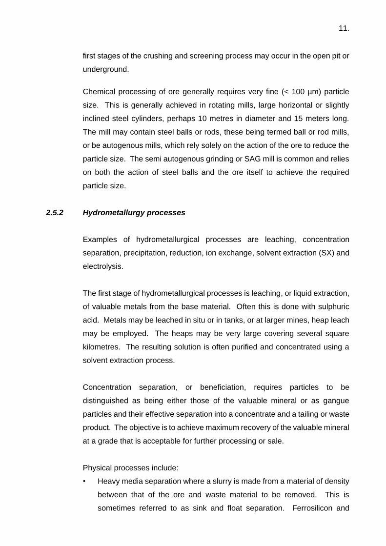
2.5.2 Hydrometallurgy processes Examples of hydrometallurgical processes are leaching, concentration
separation, precipitation, reduction, ion exchange, solvent extraction (SX) and
electrolysis.
The first stage of hydrometallurgical processes is leaching, or liquid extraction,
of valuable metals from the base material. Often this is done with sulphuric
acid. Metals may be leached in situ or in tanks, or at larger mines, heap leach
may be employed. The heaps may be very large covering several square
kilometres. The resulting solution is often purified and concentrated using a
solvent extraction process.
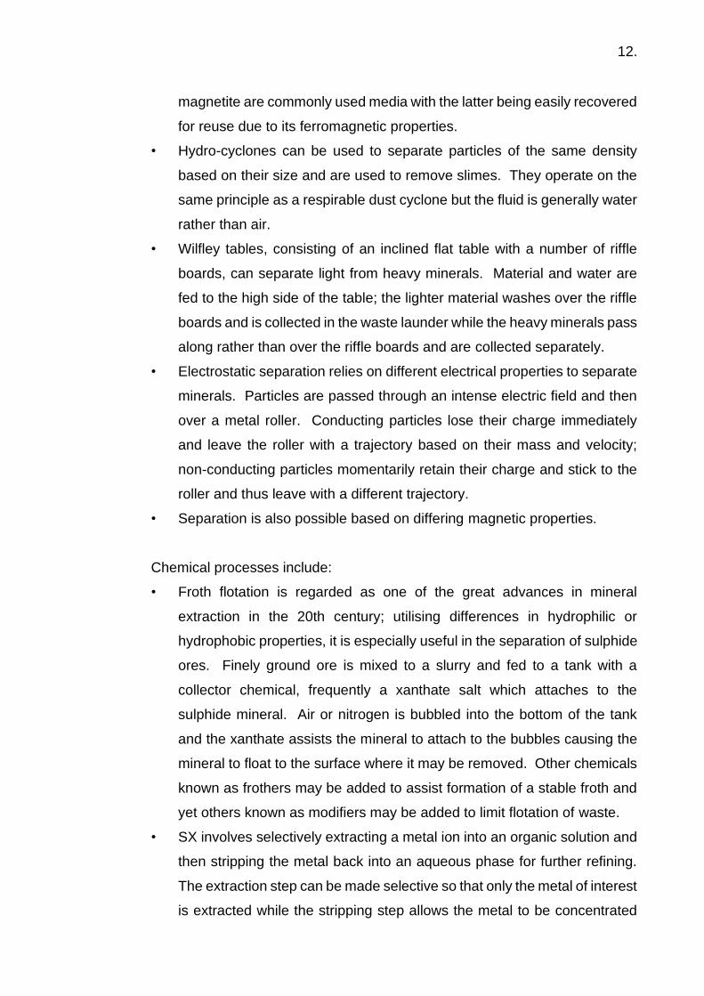
Concentration separation, or beneficiation, requires particles to be
distinguished as being either those of the valuable mineral or as gangue
particles and their effective separation into a concentrate and a tailing or waste
product. The objective is to achieve maximum recovery of the valuable mineral
at a grade that is acceptable for further processing or sale.
Physical processes include:
• Heavy media separation where a slurry is made from a material of density
between that of the ore and waste material to be removed. This is
sometimes referred to as sink and float separation. Ferrosilicon and
12.
magnetite are commonly used media with the latter being easily recovered
for reuse due to its ferromagnetic properties.
• Hydro-cyclones can be used to separate particles of the same density
based on their size and are used to remove slimes. They operate on the
same principle as a respirable dust cyclone but the fluid is generally water
rather than air.
• Wilfley tables, consisting of an inclined flat table with a number of riffle
boards, can separate light from heavy minerals. Material and water are
fed to the high side of the table; the lighter material washes over the riffle
boards and is collected in the waste launder while the heavy minerals pass
along rather than over the riffle boards and are collected separately.
• Electrostatic separation relies on different electrical properties to separate
minerals. Particles are passed through an intense electric field and then
over a metal roller. Conducting particles lose their charge immediately
and leave the roller with a trajectory based on their mass and velocity;
non-conducting particles momentarily retain their charge and stick to the
roller and thus leave with a different trajectory.
• Separation is also possible based on differing magnetic properties.
Chemical processes include:
• Froth flotation is regarded as one of the great advances in mineral
extraction in the 20th century; utilising differences in hydrophilic or
hydrophobic properties, it is especially useful in the separation of sulphide
ores. Finely ground ore is mixed to a slurry and fed to a tank with a
collector chemical, frequently a xanthate salt which attaches to the
sulphide mineral. Air or nitrogen is bubbled into the bottom of the tank
and the xanthate assists the mineral to attach to the bubbles causing the
mineral to float to the surface where it may be removed. Other chemicals
known as frothers may be added to assist formation of a stable froth and
yet others known as modifiers may be added to limit flotation of waste.
• SX involves selectively extracting a metal ion into an organic solution and
then stripping the metal back into an aqueous phase for further refining.
The extraction step can be made selective so that only the metal of interest
is extracted while the stripping step allows the metal to be concentrated

13.
into solution. The extracting chemicals can be specific to a particular
metal and are often in relatively low concentration in a bulk organic phase
such as kerosene. Modifying chemicals may be used to increase the rate
of the extraction process. The chemicals and solvents are generally re-
used in SX.
Metals and chemicals may be recovered or purified from aqueous solutions
which are generally strongly acidic using electricity or precipitation processes.
Electrowinning, or electrolytic refining, is used to extract or recover a non-
ferrous metal (e.g. copper, zinc, lead, gold, silver, chromium, cobalt and
manganese dioxide) from solution. It involves the electrolytic deposition of
pure metal on a cathode from a sulphuric acid solution of metal salts. Closely
spaced anodes and cathodes are grouped in tanks or cells, often made from
fibreglass, perhaps 1.5 metres wide and deep and 10 or more metres long.
Vast numbers of these may be contained in a single building perhaps several
hundred metres long. The metal or compound plates onto the cathode with
the release of oxygen generally being the anodic reaction. Impurities in the
solution, including silver and gold, often form sludge in the bottom of the
electrowinning tank and can have considerable value. Fresh metal rich
solution is circulated through the cells with the spent liquor recirculated. The
Hybinette Process used in the recovery of nickel is a variation of
electrowinning.
Electrorefining is a similar process to electrowinning, used in refining
applications to improve the purity of the metals. The anode is unrefined impure
metal, which is dissolved into solution and re-plated on the cathode.
2.5.3 Molten salt processes
These processes recover metal by electrolytic means from molten salt of the
metal.
The Hall-Heroult process is used for the production of aluminium (see also
Section 6.4.1). Aluminium oxide, which is very refractory, is dissolved in a bath

14.
of cryolite (sodium aluminium fluoride) in a container called a pot or reduction
cell, which is similar in dimensions to electrowinning cells. Low voltage high
current electricity is passed through the bath and aluminium produced at the
cathode. Pot or reduction lines at aluminium smelters are of similar
dimensions to cell houses.
Sodium and other reactive metals can also be produced by electrolysis of their
molten salts.
2.5.4 Pyrometallurgical processes
These require high temperatures and examples are the reduction of materials
containing metal oxides (e.g. hematite iron ore comprising of Fe2O3) and
different thermal pre-treatment techniques (e.g. roasting, smelting of sulphide
minerals and fire refining). Iron, steel, zinc, lead, magnesium and ferrous
compounds are usually produced by reduction with carbon in a shaft furnace.
These smelting processes occur in large furnaces with the largest blast
furnaces equivalent in height to perhaps a 10-story building and having an
internal volume in excess of 5,000 cubic meters. The process consists of using
carbon and heating or burning it in the presence of the metal oxide for an
overall reaction of: metal oxide + carbon => metal + carbon oxide.
Carbon monoxide is the reductant and is able to diffuse through the charge.
Heat for the reaction is provided by burning additional carbon than is
necessary for the reaction by blasting hot air into the furnace (blast furnace) or
by electricity in submerged arc furnaces. Impurities are generally reacted with
calcium oxide to form a calcium aluminosilicate slag, which floats on the molten
metal in the furnace and can be separated by gravity. These furnaces produce
molten metal and molten slag which may be at a temperature exceeding
1200˚C.
The vast majority of metal from blast furnaces is iron although lead and zinc
can also be produced, while electric furnaces produce a range of metals and
alloys such as ferronickel, ferromanganese and ferrochrome.

15.
Flash furnaces are used to smelt sulphide ores, usually copper or nickel. Ore,
flux and hot air are injected into the top of the furnace and the reaction burns
the sulphide to sulphur dioxide and iron sulphide to oxide which reacts with the
flux to form a slag. The copper or nickel matte produced is then further
processed.
Roasting is an important pyrometallurgical process. Sulphatising roasting is
used in the production of copper, nickel, cobalt and zinc. Its purpose is to
separate the metals in the sulphide ores so that they can be transformed into
a water-soluble form for further hydrometallurgical processing.

16.
3. ROLE OF THE HYGIENIST IN THE MINING INDUSTRY 3.1 Functions of hygienists in the HSE team
The occupational hygiene function in most companies falls within the Health,
Safety and Environmental (HSE) organisation, but occupational / industrial
hygiene’s relationship to the other functions varies both between companies
and even within the same company over time. The hygienists may be aligned
with a safety team, a health (medical) team, an environmental team, or
sometimes may be their own team reporting directly to an HSE manager. No
one organisational model seems to be ideal and most companies tend to rotate
the hygiene function through the various possibilities every few years.
Regardless of the team alignment the hygienist occupies a distinct and valued
role within the overall HSE effort. Hygienists generally have a relatively high
degree of academic training in science and/or engineering. Most feel a strong
affinity with the profession, with a shared dedication to the health protection of
workers, scientifically based processes and techniques, and a professional
code of ethics. Occupational / Industrial hygiene practice requires the daily
application of science, mathematics, data analysis and professional
techniques specific to the field. The high level of professional and technical
expertise of hygienists earns the particular respect of colleagues in HSE and
operations and it is not uncommon to find many opportunities to help solve
problems - even beyond the immediate field of hygiene.
The definition of occupational / industrial hygiene reinforces the principle that
the primary tasks of hygienists can be organised under the key words -
anticipation, recognition, evaluation and control of workplace health hazards:
a) Anticipation
• Design review for new projects, processes or equipment
installations.
• Job hazard analysis for major maintenance tasks with emphasis on
the health hazards.

17.
• New chemical product evaluations – i.e. reviewing chemical
products proposed for use in the mining process or for maintenance
use.
• Safety and health plans for construction, demolition or remediation
projects.
b) Recognition
• Workplace surveys to identify general health hazards.
• Special surveys – i.e. asbestos fibres.
• Emergency response – i.e. identifying hazards in emergency
situations.
c) Evaluation
• Reviewing process, equipment or hazardous material physical and
chemical data to determine the level of risk for workers.
• Exposure monitoring to measure actual exposures to hazardous
agents.
• Decision making regarding the relative risk of exposures to health
hazard agents.
• Documentation of exposure assessments.
d) Control
• Design controls for the protection of workers from health hazard
agents.
• Apply controls preferentially according to the occupational hygiene
hierarchy of controls.
• Check control systems to assure they are working effectively:
▪ Hygienists should periodically check the flow in exhaust
ventilation systems to ensure that they are working properly and
are capable of capturing and entraining air contaminants.

18.
▪ Observing the use of PPE on the job to assure it is being used in
a manner so as to assure reasonable protection is also an
important task.
• Design and implement administrative control programmes such as
for hearing conservation, respiratory protection, blood borne
pathogens, radiological protection.
• Train workers to understand the hazards of their work place and
how to protect themselves by applying the necessary controls that
are in place.
3.2 Integration of hygiene into the HSE function
In a well-functioning HSE Department, hygienists should be integrated with
and share tasks with their colleagues in the Safety and Environmental teams.
Safety advisors are often more plentiful than hygienists and usually can spend
more time than the hygienists in the actual workplaces observing the work.
They can be extended eyes and ears who alert the hygienist to a new
maintenance task with potential health hazard exposure. Sometimes they can
help with exposure monitoring under the direction of the hygienist. In return,
hygienists must understand common safety requirements, and must not
overlook safety deficiencies, like missing fall protection or significant electrical
or fire hazards while conducting occupational hygiene field work. When safety
colleagues are overloaded with concurrent work the hygienist should be
prepared to help with hot work permits, confined space evaluations and the
like, provided appropriate training has been completed. Co-operation is the
key to success for all and it builds wider skills, which make the HSE team more
effective in the future.
Hygienists are particularly qualified to support compliance with environmental
regulations through their understanding of hazardous materials, and their skills
in training workers in hazards and appropriate control systems.
In many countries, environmental regulations for air pollutants like asbestos
require the very kinds of exposure monitoring and control systems that

19.
hygienists apply broadly in their work. The expertise of the hygienist can add
confidence that such evaluations are being conducted according to both
regulatory requirements and best professional practice.
3.3 Emergency response
The hygienist also has an important role in supporting emergency response
actions at sites. Spills and gas or vapour releases are chemical hazards that
need to be properly identified, evaluated and controlled. A hygienist is
essential to the decision making process on the emergency response and may
even need to make measurements of hazards during the evolving response.
Responses may be made in challenging thermal conditions (either hot or cold)
and in most responses, there is heavy dependence on PPE. The response
leader needs advice on the level of potential exposure and the appropriate
PPE for the responders. The hygienist may also need to oversee a
decontamination operation. To contribute effectively in actual responses, it is
important that the hygienist participate in drills and other emergency response
practice opportunities and fully understands the tasks of fire fighters and spill
responders. The hygienist should be sufficiently experienced and practiced to
serve as an incident response safety officer if required.
3.4 Addressing occupational hygiene issues 3.4.1 Introduction
Issues involving occupational hygiene, like other occupational health and
safety (OH&S) matters, may arise in a number of ways; for example, employee
complaints, an incident on-site, union concerns, site audits, industry
organisation initiatives, regulatory directives or management initiated
investigations.
How these issues are managed depends on many factors including; the
perceived severity of the complaint, the underlying industrial relations on-site,
the influence of the issue on production, managerial commitment to OH&S and
local attitudes to the importance of good health at work.
The two principal approaches to addressing occupational hygiene issues are:

20.
• On an immediate basis depending on the issue at hand; and
• In a long-term structured manner.
Cases as to the merits (or otherwise) of each approach can be argued,
however the aim of this Manual is to provide guidance to mine personnel for
both types of situations.
3.4.2 Immediate issues Unfortunately, immediate resolution of occupational hygiene issues rarely
occurs in practice, with more often than not an agreement between
management and employees being required on the means of resolution. The
following process should assist in resolving issues that arise in this manner
and prevent some form of a crisis.
STEP 1 ISOLATE AND DEFINE THE PROBLEM
In many cases the facts of the situation are influenced by emotion
or interpretation as the issue is passed up the reporting structure.
Because of this there is a need to clearly identify what the issue is
and the way it impacts on those involved. It is important that the
workplace in question be physically inspected by the person(s)
investigating the problem to ensure that there are no other
contributing factors than those alleged to be the cause of the
problem.
Such an inspection should always, when possible, be made in the
company of the individual who initiated the concern, as it is
important to be sure that all the conditions encountered are the
same as those prevailing when the problem arose.
In defining the problem, it is important to be sure all the facts have
been collected; for example, which hazardous products, if any, were
involved and had each Safety Data Sheet (SDS – previously termed

21.
Material Safety Data Sheet) been reviewed and recommendations
for control of any exposures applied.
It is also important to be sure that no unexpected changes to the
process have occurred - check production records, simulate the
situation once again.
STEP 2 EVALUATE THE PROBLEM
Depending on the extent of the problem, evaluation may be possible
using on-site resources, but in some cases external expert opinion
may be necessary. It is difficult to state at which time environmental
monitoring (e.g. dusts, vapours, fibres, etc) becomes a preferred
option. In many cases, monitoring will not add anything to the
debate in terms of its resolution, and in others the need for
monitoring is obvious, for without it the resolution of an industrial
relations issue may be impossible. Reading the SDS (if one exists
for the material(s) involved in the process) may indicate the
potential for hazardous substances which require environmental
monitoring. Otherwise, general observation can provide guidance;
e.g. fumes exist in the workplace, strong smells are evident, etc.
Care should be exercised when using the nose as a monitoring tool,
as many gases are odourless and others can numb the senses.
Also, exposure standards for some gases could be below their
odour threshold.
STEP 3 CONTROL THE PROBLEM
In many cases a simple resolution for the problem may emerge from
the site inspection. In others, detailed engineering modifications
may be necessary. The emphasis should be on a permanent
solution, not just a "quick fix", as these rarely work and may
exacerbate the situation.

22.
STEP 4 FOLLOW UP
Once a workable solution to the problem has been found, the
process should not be considered finished. Implementation of the
designated control technology is just as important as identification
of the problem. Poor implementation procedures may result in the
problem giving rise for concern at a later stage. Sometimes a
recommended solution has been imposed upon the workforce
rather than by involving them in consultation and explanation,
resulting in a reluctance on their part to modify their daily practice.
The best approach is to introduce a follow up procedure for a period
of time during which the views of all involved are sought as to the
effectiveness of the control strategy. A final close out inspection
should be made of the area to ensure that the final solution is
understood and accepted by the workers, effective, being used and
routinely maintained.
3.4.3 A structured approach
A structured approach to the management of occupational hygiene issues at
mines will highlight issues requiring urgent attention and resources but still
recognise the importance of apparently less urgent issues. It should be
understood that for an initial period “crisis issues” may still occur, however in
the long term such incidents and consumers of resources will decline to the
benefit of all involved.
Given the long-term approach, it is important to understand that in most
instances “quick fix” solutions rarely resolve a problem and may result in
delays to resolution. It is better to seek a more sustainable solution, though it
may take longer to develop. This may not satisfy all parties but it may
ultimately be the best way to achieve a permanent solution. Sometimes
temporary solutions (e.g. use of PPE) may still be needed to ensure that the
health of employees is not put at undue risk as longer term resolution is
undertaken.

23.
STEP 1 IDENTIFY HAZARDS PRESENT ON-SITE
While this may sound like a relatively easy task, experience has
shown that in many cases “familiarity breeds contempt” with
significant issues being overlooked. Consequently, if this structured
approach is to be successful, all preconceived opinions on an issue
should be put to one side and the process commenced from an
objective base.
As a starting point, it is suggested that the group members
(e.g. Occupational Health & Safety Committee) should have a short
session with all available sources of relevant information on the
issue. Possible areas for consideration are:
• OH&S Committee minutes
• Deputy / Examiner reports
• First aid treatment records
• Grievance reports
• Mines Department incident notices
• Industry association guidelines
• Union publications
• Audit reports
and any other avenue for acquiring relevant information.
To complement the above information and to gain some
perspective on the specific issue on-site, conduct a walkthrough
audit of the site. Remember to keep a record of the walkthrough
audit and if possible, photograph or video key points for records, or
analysis, at a later stage. Sometimes a timed video record of an
operation will be useful. Although outside expert assistance may
be employed to perform this step, greater benefit is derived if the
process is initially performed by site personnel. It may then be
useful to confirm the list of issues by the use of outside expertise if
resources are obtainable.

24.
Once all the information has been collected it should be collated
into a single document in logical alphabetical order ready for Step 2.
STEP 2 ASSIGN PRIORITIES TO ISSUES
This is a major step in the process as it determines the allocation of
time and resources to individual issues and thus the outcome must
be defendable to those individuals who see another issue at a
higher level of priority.
Conduct a basic risk assessment on the first issue listed. Many
methods exist within industry to complete this task, all of which are
based on the premise that the risk associated with any undesirable
incident is a combination of the probability of it occurring and the
severity of associated consequences, or expressed as an equation:
Risk = Consequence (Hazard Severity) x Likelihood (Probability of Exposure)
If your site currently uses a risk matrix for occupational health and
safety issues, use that matrix for your risk ranking.
Repeat this process for every issue on your list of identified issues
and construct a priority list of occupational hygiene issues based on
the risk rankings for your site ready for Step 3.
STEP 3 EVALUATE THE LEVEL OF RISK
Commencing with the highest priority issue, evaluate the actual
level of health hazards for individuals working in each area. In many
cases, simple observation will give some insight as to the level of
hazard, but in others workplace monitoring, usually atmospheric,
may be required. If monitoring appears necessary and you are
unsure of what is required, seek expert assistance as wrong
interpretation of monitoring data may give some situations a falsely
serious importance or significance. It may also be necessary to
develop a statistically based monitoring strategy to evaluate large
scale issues or those involving numerous workers.

25.
The relationship between exposure and its impact on health should
be considered when evaluating issues. If it is a fast-acting irritant
like ammonia, don’t measure the contaminant over a whole shift.
Conversely if someone is exposed to a long-term contaminant such
as airborne quartz dust briefly and incidentally once in a while, don’t
be overly alarmed, but do expect to need a long-term monitoring
programme if quartz dust levels are significant.
STEP 4 DEVELOP CONTROL STRATEGIES
Commencing with the highest priority issue, develop a range (if
possible) of control strategies. This may be another situation where
expert advice is necessary.
Having identified the need for control measures it is constructive to
involve the people actually working in the area in the development
discussions as past experience has shown that externally imposed
solutions do not always gain full acceptance. Also, in many cases
simple alternatives may be clearer to those who work in an area
than to visitors. Finally make a recommendation to management if
change is considered necessary.
STEP 5 OVERSEE IMPLEMENTATION OF NEW CONTROLS
It is important to ensure that the controls considered necessary are
correctly implemented and are explained to those workers expected
to either use them or be subjected to their influence. Where
engineering controls are implemented, it is important that the
correct operation of the controls is described, operating parameters
are documented, maintenance requirements included in routine
maintenance programs and relevant spare parts acquired.

26.
STEP 6 ONGOING REVIEW
As with the case described in the previous section of this Manual,
follow up of the application of a solution to a problem is really part
of the solution and extremely important.
In the structured approach, it is recommended that the
effectiveness of the solution is evaluated by visual or technical
means and this information is recorded in a format so others can
access it at some time in the future.
It will also aid in the detection of ineffective solutions. Over time this
will build a resource of workable solutions which can be applied
whenever a similar problem arises.
It is good practice to conduct a final risk assessment after the
chosen solution has operated for a reasonable period to be sure
that all possible eventualities have been covered and the solution
to one problem hasn’t either created or unmasked another issue.
If this final risk assessment confirms that the issue has been
resolved it should be transferred to a “maintenance list” where the
situation is revisited each five (5) years (or sooner if circumstances
require) to ensure that the control technology has not deteriorated
and personnel are again being exposed.
The process as set out above can be summarised in schematic form
as follows (Figure 3.1).

27.
Figure 3.1
3.4.4 Example: The International Council on Mining & Metals (ICMM) approach In their publication “Good Practice Guidance on Occupational Health Risk Assessment”,
the ICMM suggests a similar approach to that described in Section 3.4.3. This is just one
example of an approach that has been developed and is used within the mining industry.
There are several others that are available and can be sources through the local, national
and professional organisations. The ICMM suggest that a Health Risk Assessment (HRA)
involves four key elements, these being:
• Identification of hazards;
• Examination of the potential health effects;
• Measurement of exposures; and
STEP
1IDENTIFICATION OF HEALTH HAZARDS FROM PREVIOUS
AUDITS, OH&S COMMITTEE AND PROFESSIONAL INPUT
STEP
2
STEP
3
STEP
4
STEP
5
STEP
6
CONDUCT RISK ASSESSMENT ON EACH ISSUE AND
SITUATION TO ESTABLISH PRIORITY LIST
COMMENCING AT THE HIGHEST RISK ISSUES EVALUATE
THE ACTUAL LEVEL OF INDIVIDUAL HEALTH HAZARDS
DEVELOP APPROPRIATE CONTROL STRATEGIES AND MAKE
RECOMMENDATIONS TO MANAGEMENT
OVERSEE IMPLEMENTATION OF NEW CONTROLS
ONGOING REVIEW OF CONTROL MEASURES AND
PROGRAMME

28.
• Characterisation of the risk.
The ICMM suggest that there are three types of HRAs, these being:
• Baseline HRAs;
• Issues based or targeted HRAs; and
• Continuous HRAs.
These are defined by the ICMM as:
A baseline HRA is used to determine the current status of occupational health
risks associated with a facility. This tends to be a very wide ranging
assessment that encompasses all potential exposures.
An issues-based or targeted HRA is designed to provide a detailed
assessment of specific processes, tasks and areas that have been identified
as priorities in the baseline assessment.
A continuous HRA is an ongoing monitoring programme or a schedule of
regular reviews to determine whether conditions have remained the same,
whether changes in processes, tasks or areas have occurred and whether
these changes have modified any hazardous exposures and hence any
potential health risks. A management of change programme can also be
considered as being part of a continuous HRA programme.
An HRA can be qualitative involving an informed assessment of exposures
and/or risks (e.g. baseline HRAs) or quantitative involving the measurement
of exposures and/or the quantification of the potential health risks (e.g. issues
based HRAs).
The ICMM process is illustrated schematically in Figure 3.2.

29.
(Source: ICMM – with permission)
Figure 3.2 – ICMM Health Risk Assessment Process
The ICMM also note that critical control management should be an integral
part of risk management. It focuses on identifying and managing the controls
that are critical to preventing catastrophic or fatal events, as detailed in their
“Critical Control Management Implementation Guide”.
The Australian Institute of Occupational Hygienists (AIOH 2006) publication
“Simplified Occupational Hygiene Risk Management Strategies” outlines the

30.
procedure for a baseline risk assessment and notes that a suitable and
sufficient occupational health risk management programme requires the
following elements:
• Workplace characterisation;
• Hazard identification;
• Exposure characterisation;
• Risk assessment;
• Risk control or treatment;
• Monitoring and review of controls; and
• Documentation of the risks identified and the actions decided upon.

31.
4. BASIC OCCUPATIONAL HYGIENE PROGRAMMES 4.1 Hazard communication – SDS systems, chemical inventories, training
Hazard communication programmes are an important component of health
management programmes because they give workers the information they
need to protect themselves from workplace health hazards. No employer can
afford to have an hygienist or safety advisor overseeing all work to see that
each and every worker is avoiding unhealthy exposures. Each worker has to
have some basic health and safety skills so they can take care of themselves
and their co-workers. While some hazard communication programmes focus
only on chemical hazards, others also include physical agents such as noise
and vibration. Typically, hazard communication programmes cover:
• Training: Workers need to understand hazards in their work and how to
protect themselves during both routine work and in emergency situations.
When there are control systems in place, workers have to understand
how to use them properly.
• Chemical inventory: This is an inventory of all chemical products in the
facility indicating where they are and the SDS number for each, usually
maintained on a web-hosted SDS/chemical inventory system. The web
host is a firm that specializes in storing maintaining, and making available
SDSs and chemical inventories for their clients.
• Safety Data Sheet systems: Today SDSs are generally kept
electronically on a web-hosted system. Workers need training on how to
use the electronic system to find and print an SDS, and they need to
know how to interpret the document to understand the hazards of the
chemical product they are using and the controls necessary for safe use.
• Labelling of chemical containers: There needs to be a means of
assuring that containers of chemical materials are properly labelled with
the name of the material and any key hazard, such as flammable, toxic
or corrosive.
Original containers, temporary transfer containers and storage tanks
should all be labelled with sufficient information to allow any worker to
find the relevant SDS.

32.
• New chemical product evaluation and approval system: This is a
system in which a potential user of a new chemical must first file a request
for review and approval with the occupational hygiene team. The
hygienist reviews the SDS, fills in gaps in information if necessary, and
either approves or denies the purchase of the product. This system may
be a utility in the web-hosted SDS/chemical inventory system. A new
chemical evaluation request also alerts the hygienist that a new chemical
is about to be used, perhaps in a new task and where. For example, the
maintenance shop crew is about to recoat their entire shop floor with a
polyurethane deck paint on Friday afternoon. The hygienist may
recommend specific respirators for the painters and monitor their
exposures to paint solvents. It may be necessary to alert people in offices
nearby and set up temporary exhaust ventilation in the shop to keep
vapours out of the adjacent occupied spaces.
There is much more detail on hazardous materials management in the mining
industry in the Australian Government (2016) publication “Leading Practice
Handbook: Hazardous Materials Management”.
4.2 Hearing conservation
Noise is the most prevalent occupational health hazard for workers in the
mining industry, and is discussed in more detail at section 5.2. For many sites
noise is the only health hazard to which mining and mineral processing
workers are exposed above the occupational exposure limit (OEL) on a
regular, even daily, basis. Hearing protective devices are commonly used to
protect such high noise-exposed workers but the effectiveness of hearing
protection use varies widely from one place to the next, and even between
individual workers at any site. When workers are exposed to high noise on the
job it is essential that they be enrolled in an effective hearing conservation
programme. Elements of a hearing conservation programme include:
• Noise surveys of workplaces to identify noise-hazardous locations,
equipment and tools.

33.
• Identification of hazardous noise areas, equipment and tools with
warning signs or stickers. A site survey should cover both routine and
non-routine situations. It is also helpful to put noise warning (“hearing
protection required”) stickers on hazardous-noise portable equipment
like petrol- or diesel-powered generators and pumps, and on hazardous-
noise power tools like disc grinders, impact wrenches, saws, needle
guns, and particularly any air-driven equipment.
• Exposure monitoring of Similar Exposure Groups (SEGs) using personal
dosimetry to quantify the exposure profile of each group (see section
7.2.1).
• Determination of which SEGs should be enrolled in the programme.
• Provision of approved hearing protective devices where noise exposures
cannot be reduced by other means.
• Audiometric testing of workers, including procedures for testing,
evaluating audiograms, determining threshold shifts, and case
management.
• Fitting of hearing protection. This may best be done in the clinic at the
time of the audiometric exam. Some sites are now using fit testing
systems that check the quality of the fit as the worker is wearing the
hearing protection.
• Training of workers to maintain awareness of the hazard and how to use
hearing protection properly.
• Design review of projects, facility upgrades, renovations and equipment
replacements, to ensure that feasible noise controls are utilised.
As with many workplace exposure management programmes, an effective
hearing conservation programme requires close coordination between the
occupational hygiene and medical teams. Hygienists need to give the medical
team monitoring data for SEGs and help with the evaluation of hearing loss
cases. The medical team needs to ask the hygienists for exposure information
when they have a case in order to assess work-relatedness. Case information

34.
fed back to the hygienist may help identify weakness in use of hearing
protection or other aspects of the programme.
There is much more detail on hearing conservation programmes included in
the Student Manual “Noise: Measurement and Its Effects”, at the NIOSH
webpage “Noise and Hearing Prevention” and from the Safe Work Australia
(2015) “Model Code of Practice - Managing Noise and Preventing Hearing
Loss at Work”.
4.3 Dust / respiratory protection
Exposure to dust and other particulates has also been the bane of the mining
industry. According to Cecala et al (2012), the five areas within the mining and
mineral processing industry which typically produce particulate (dust & fume)
exposures that should be controlled are as follows:
• The transfer points of conveying systems, where material falls while being
transferred to another piece of equipment. Examples include the
discharge from one belt conveyor to another belt conveyor, storage bin, or
bucket elevator.
• Specific processes such as crushing, drying, screening, mixing, blending,
bag unloading, smelting, welding and thermal cutting, and truck or railcar
loading.
• Operations involving the displacement of air such as bag filling or
pneumatic filling of silos.
• Outdoor areas where potential dust sources are uncontrolled, such as core
and blast hole drilling.
• Outdoor areas such as haul roads, stockpiles, and miscellaneous unpaved
areas where potential dust-generating material is disturbed by various
mining- or process-related activities and high wind events.
Atmospheric dust can cause irritation to the upper respiratory tract and eyes,
obscure vision hence cause safety hazards, and can give rise to a number of
lung disorders or diseases. One of these diseases is pneumoconiosis, a term
proposed by a researcher in 1866 as a general term for lung diseases caused

35.
by dust inhalation. In fact, various types of pneumoconiosis can be induced
by over-exposure of workers to the dusts of many agents, including:
Hematite (iron oxide) - Siderosis
Antimony (compounds) - Antimony Pneumoconiosis
Barium (compounds) - Baritosis
Tin (compounds) - Stannosis
Asbestos - Asbestosis
Silica - Silicosis
Many of these pneumoconioses are benign and merely show up as shadows
on workers’ X-rays. Silicosis on the other hand has been linked to lung cancer
and is a debilitating and often fatal disease in its own right (discussed in more
detail at section 5.11).
Other pneumoconioses, such as asbestosis, berylliosis (from the dust of
beryllium) and coal workers’ pneumoconiosis, are much more harmful and lead
to the development of fibrosis of the lungs.
Coal workers’ pneumoconiosis results from the gradual accumulation of coal
dust particles within the lung tissue, usually over a period of many years. As
with all dusts, most of the dust that is inhaled does not lodge in the lungs. The
larger particles are trapped in the nose and throat and the very smallest
particles are exhaled in the same breath.
Only the dust particles in the less than 7 micrometre (µm) size range
(respirable dust) are deposited and the lungs have special clearance
mechanisms to remove most of these particles over the course of the next few
days or weeks.
The respirable dust which is not cleared aggregates to form nodules which can
be seen at post mortem or on a chest X-ray examination. Generally, at least

36.
20 to 30 years of exposure is necessary to produce any significant degree of
disease.
In 1780 the first successful attempt to distinguish between pneumoconiosis
and tuberculosis was provided by Ackerman, but this distinction was not
appreciated at the time. By the early 1800’s considerable evidence was
emerging regarding the nature of disease experienced by workers in mining
operations (especially with respect to lung disorders). It is interesting to note
that in the UK by 1852, occupational diseases (mainly lung diseases) extracted
a bigger toll on miners’ lives than major mine disasters, which were themselves
quite frequent at the time. As a result of a series of Acts in the UK parliament
in the 1850’s, the position improved, but respiratory disease remained a major
hazard in the coal mining industry.
In Australia, a similar picture developed with coal workers’ pneumoconiosis
being a major problem in the coal industry; as demonstrated by the fact that in
1948 16% of the NSW coal mining workforce displayed some level of this
disease.
The ILO classification of x-rays is a method of grading based on x-ray appearance and may be in practical
terms interpreted as the following:
ILO+1 = People with diagnostic features of dust exposure but no clinical symptoms
ILO+2 = People with more severe dust exposure than above and likely to have symptoms
(Source: CMTS – reproduced with permission)
Figure 4.1
Pneumoconiosis Prevalence
NSW Coal Industry, 1970-1999
0
1
2
3
4
5
6
7
8
1965 1970 1975 1980 1985 1990 1995 2000 2005
Year
Rate
per
hundre
d m
inew
ork
ers
ILO+1
ILO+2

37.
Improvements over the years (Figure 4.1) were mainly due to major alterations
to the mining practices and ventilation systems used in underground coal
mines. Despite the introduction of mechanisation to the industry in the 1950’s,
the incidence of coal workers pneumoconiosis continued to decline and
although some problems with dust control have occurred since the introduction
of longwall mining in the 1960’s, most have been resolved where extensive
monitoring programmes and the introduction of appropriate engineering and
procedural controls have been implemented. Unfortunately, a level of
complacency has emerged following decades of a low incidence of disease.
There has been an increase in the prevalence of these diseases in more recent
times which can be seen in Figure 4.2, the NIOSH Coal Workers’ X-ray Pro-
gram from 1970–2009. In 2016 a similar increase was identified in the
Australian Queensland mines (Queensland Government 2017).
Figure 4.2. Percentage of miners examined with PMF from the NIOSH
Coal Workers’ X-ray Program from 1970–2009, by tenure in coal mining.
(Source: NIOSH CWXSP data).
Generally, pneumoconiosis can be prevented provided exposure to respirable
dust is maintained below statutory levels.
Another factor in exposure to respirable dust is the possible presence of silica
(quartz). This can result in silicosis if exposures are significant. It is thought

38.
to play a role in the development of lung cancer, although the pathway and
mechanism for this are not yet clear. There are sound health reasons for
keeping exposure to silica as low as possible.
In most countries, specific ventilation, monitoring and exposure levels are
provided in legislation, which should be observed in order to minimise the
occurrence of lung disease.
Another issue is that of inhalable dust (the total of all dust size fractions
inhaled). This comes about from concern first raised in the British Coal
Workers compensation case regarding chronic obstructive pulmonary disease
(COPD). Work by some researchers has indicated that workers on longwalls
and in continuous miner panels may be exposed to elevated levels of this dust
fraction.
While there is a recommended standard of 10 mg/m3 for inhalable dust not
otherwise specified, there are suggestions that this should be lower and be
accompanied by medical surveillance of respiratory symptoms for possible
correlation with inhalable dust levels.
When workers are exposed to high dust levels on the job it is essential that
they be enrolled in the most effective respiratory protection programme
possible. Elements of a respiratory protection programme include:
• Dust / fume surveys of workplaces to identify hazardous locations,
equipment and processes.
• Identification of hazardous dust areas, equipment and processes with
warning signs or stickers. A site survey should cover both routine and
non-routine situations.
• Exposure monitoring of SEGs using personal monitoring to quantify the
exposure profile of each group (see section 7.2.1).
• Determination of which SEGs should be enrolled in the programme.

39.
• Provision of approved respiratory protective devices, where dust
exposures cannot be reduced by other means.
• Lung-function testing of workers, including procedures for testing,
evaluation of spirometry results, and case management.
• Fitting of respiratory protection. This may best be done in the clinic at
the time of the lung-function exam. Most sites are now using fit testing
systems that check the quality of the fit as the worker is wearing the
respiratory protection.
• Training of workers to maintain awareness of the hazard and how to use
respiratory protection properly.
• Design review of projects, facility upgrades, renovations and equipment
replacements, to ensure that feasible dust controls are utilised.
An effective respiratory protection programme requires close coordination
between the occupational hygiene and medical teams.
There is much more detail on dust prevention and respiratory protection
programmes included at the NIOSH webpages “Mining Topic: Respirable
Dust” and “For Respirator Users”.
4.4 Ergonomics
Ergonomically-related musculoskeletal injuries and illnesses rank near those
for noise induced hearing loss in frequency for many mining sites. They
include sprains and strains of muscles, tendons and ligaments; tendinitis; back
injuries; back and neck pain in the absence of discrete trauma and identifiable
injury; joint injuries, including injuries to the shoulder, elbow, wrist, hip, knee,
ankle and joints in the hands and feet; nerve injuries (e.g. carpal tunnel
syndrome); soft tissue hernias (e.g. abdominal hernias); and occupational
overuse syndrome (OOS) and cumulative trauma disorder. Ergonomic issues
fall into three primary categories, affecting totally different groups of workers:
• Industrial (operating and maintenance personnel at industrial worksites);

40.
• Office (mostly computer workstation situations, but also other office
tasks). A special case of this category is control rooms; and
• Service (workers in fly in / fly out type operations who are involved in
providing meals and cleaning and servicing accommodation).
However, there are common contributing elements including:
• Awkward positioning.
• Inefficient arrangement of work or work station.
• Poorly designed tools.
• Repetitive motion.
• Personal fitness.
Mining workers have a wider variety of activities than, say, assembly workers
in a manufacturing plant. They don’t do the same repetitive motions all day
but they move around a lot dealing with machinery whose layout and
accessibility are not always worker-friendly.
Mechanics also are assigned a wide variety of tasks from day to day. Many
will involve breaking free hard-to-reach nuts, from an awkward position, using
hand tools or pneumatic impact wrenches. Electricians must frequently work
with their arms raised to reach circuits and devices mounted overhead.
Repetitive use of a screwdriver overhead can become very uncomfortable.
Heavy manual handling is common in maintenance work. Compact equipment
may have very little room to work, or to manoeuvre or lay down large
components.
Office computer workstation ergonomic issues in the mining industry are
probably little different from office workstation issues in most other industries.
Control room workstations are different from regular office workstations and
present some special challenges. Quite often they are designed with a single
flat work surface, un-adjustable in height, in front of an array of monitors that
display conditions in the mine.

41.
The control board may be worked by several operators around the clock, and
for remote sites operators may work two-week alternating tours. In the control
room environment, it is important that operators are provided with adjustable
chairs to accommodate workers of different sizes, that control panels are
arranged for easy viewing and information displayed is limited to that which is
critical.
Service personnel (e.g. cooks & cleaners) usually have less variety in the tasks
they perform, compared to the mine workers, often performing the same
repetitive motions all day.
The control responses largely fall into two classes:
• Engineering (redesign the work, workstation, tools or equipment used to
eliminate the ergonomic stress); or
• Coping (help workers make the most of an undesirable ergonomic
situation through coping methods, like breaks, stretches, manual
handling techniques, positioning and movement techniques, personal
fitness improvements).
The occupational hygiene hierarchy of controls suggests putting the most
emphasis possible on the engineering approach (assuming the hazard cannot
be eliminated entirely). An engineering solution will be more effective than
coping solutions because it is less dependent on worker training and diligence.
Coping methods require constant training, reminders, oversight, and
reinforcement and are unlikely to be consistently effective.
In practice, an ergonomic programme is likely to draw on both means.
Ergonomic work stress is not always amenable to engineering relief, either
because there is no feasible means of doing so, or because the cost of a retrofit
is prohibitive. Had ergonomic stresses been eliminated or reduced in the
original design of the facility work today would be easier and more productive.

42.
Ergonomic problems in a mine or processing plant need to have their own
specific evaluation and individual fix.
Elements of the ergonomic programme may include the following:
• Surveys of workplaces to identify and recommend corrections for:
- Conditions such as poorly designed or located valves, or other
operating or maintenance points, that force workers to work or exert
force in awkward positions
- Tools or equipment used for maintenance that could be improved
or replaced to reduce ergonomic stress
- Tasks with repetitive nature that could contribute to cumulative
trauma
- Poor manual handling practices contributing to musculoskeletal
stress.
• Office workstation evaluations and improvements:
- Use of web-based or checklist-based self-assessments and advice
- Follow up by a trained workstation assessor for problematic
workstations or for workers who are symptomatic
- Additional surveys of office conditions to identify problems beyond
workstations - such as storage areas where awkward lifting may be
a problem
- Selection and procurement of ergonomically-designed and
appropriate chairs and work desks.
• Design review of projects such as office or control room renovations,
facility expansions or upgrades, and equipment replacements to assure
that ergonomic design is enhanced where possible.
• Training of workers to cope with unavoidable ergonomic stresses:
- Lifting and manual handling techniques
- Movement training — how to position oneself to apply force,
maintain balance, carry things, use stairs, avoid slipping and falling,
etc
- Self-care including stretches to maintain flexibility, warming up,
pacing and varying work.

43.
• Health promotion and fitness programmes to maintain flexibility, balance,
and strength for the job.
• Case management for symptomatic workers:
- Medical assessment and intervention as indicated
- Occupational hygiene evaluation of worker’s worksite and activities
- Specific fitness and flexibility programme for the worker as indicated
by medical assessment.
A participative ergonomics approach has been demonstrated to be effective in
controlling manual task injury/illness risks and as such should be employed.
There is more detail on ergonomics and musculoskeletal injury / illness
prevention programmes included at the NIOSH webpage “Mining Topic:
Ergonomics and MSD Prevention” and the UK HSE webpage “Musculoskeletal
disorders”.
4.5 Confined spaces
Each year a number of people lose their lives unnecessarily when working in
confined spaces. In most incidents, little attention is paid to assessing the
situation and many foolish people enter confined spaces without knowing the
nature of the environment in the confined space. In other incidents, they
inadvertently generate toxic gases, by which they are overcome, during their
work activities within the confined space.
To reduce these incidents, statutory authorities have produced either
regulations or codes of practice to control work in confined spaces. In Australia
an Australian Standard on confined space entry (AS/NZS 2865) was produced
and is the common denominator for regulatory control used by OH&S
authorities across Australia. The following section concentrates on this
Australian Standard and attempts to highlight those procedures that should be
adopted before entry to any confined space at a mine site is undertaken.
Guidelines (HB 213:2003) for safe working in confined spaces have also been
produced by Standards Australia, and there is a Safe Work Australia (2016)
“Model Code of Practice - Confined Spaces”.
44.
Similar information can also be found in:
• ANSI Z117.1 Committee. American Society of Safety Engineers (ASSE).
• UK HSE publications (accessed 9 December 2019)
• https://www.osha.gov/SLTC/confinedspaces/ (accessed 9 December
2019)
What is a confined space? While the definition of a confined space can vary slightly across jurisdictions,
it can be defined as being an enclosed or partially enclosed space that is not
intended or designed primarily for human occupancy, within which there is a
risk of one or more of the following:
a) An oxygen concentration outside the safe oxygen range.
b) A concentration of airborne contaminant that may cause impairment, loss
of consciousness or asphyxiation.
c) A concentration of flammable airborne contaminant that may cause injury
from fire or explosion.
d) Engulfment in a stored free-flowing solid or a rising level of liquid that
may cause suffocation or drowning.
According to the American Industrial Hygiene Association white book, a
confined space is defined as:
a) large enough and so configured that an employee can bodily enter the
space and perform assigned work,
b) has limited or restricted means for entry or exit, and
c) is not designed for continuous human occupancy. By definition, these
spaces are not particularly hazardous except they may make
emergency rescue exceedingly challenging.
In relation to mines, examples of confined spaces would include (but are not
limited to):
• Open topped spaces such as pits or degreasers, trenches deeper than
1.5 m.
• Pipes, sewers, septic tanks.

45.
• Boilers, pressure vessels, fuel tanks.
• Washery tanks, pipework, etc.
• Access tunnels beneath stockpiles, etc.
• Storage bins (above and below ground).
Assessment of confined spaces It is a requirement under most standards that for any proposed work, an
employer must identify all confined spaces and the hazards associated with
working in those confined spaces. This is normally accomplished by means
of a risk assessment conducted by a competent person(s). As a minimum, the
assessment needs to take into account:
a) the nature of the confined space;
b) the work required to be done;
c) whether it is necessary to enter the confined space;
d) the range of methods by which the work can be done;
e) the hazards involved and associated risks;
f) the actual method selected (and in particular whether the method will
alter the atmosphere in the confined space) and equipment proposed;
and
g) emergency and rescue procedures.
Risk factors
As part of the risk assessment, various factors need to be considered and
these include:
a) arrangements for rescue, first aid and resuscitation;
b) the number of persons occupying the space;
c) the number of persons required outside the space to maintain equipment
essential for the confined space task, to ensure adequate communication
with and observation of the persons within the confined space, and to
properly execute rescue procedures;
46.
d) all proposed operations and work procedures, particularly those that may
cause a change in the conditions in the confined space;
e) the soundness and security of the overall structure and the need for
illumination and visibility;
f) the identity and nature of the substances last contained in the confined
space;
g) the steps needed to bring the confined space to atmospheric pressure;
h) the atmospheric testing to be undertaken and the parameters to be
assessed before the entry permit is issued;
i) all hazards which may be encountered (for example, entrapment of
workers);
j) the status of fitness and training of those persons involved in confined
space work;
k) adequate instruction of those persons in any work procedure required
including rescue operations, particularly those which are unusual or non-
typical, including the use and limitations of any PPE and mechanical or
other equipment to be used;
l) the availability and adequacy of appropriate PPE, protective clothing and
rescue equipment for all persons likely to enter the confined space;
m) where signs:
i) comply with appropriate standards (e.g. AS 1319),
ii) indicate that entry is permitted only after a responsible officer has
signed the entry permit, in a manner appropriate to the persons at
the workplace;
n) the need for additional protective measures, for example:
i) prohibition of hot work in adjacent areas,
ii) prohibition of smoking and naked flames within the confined space
and, where appropriate, the adjacent areas,
iii) avoidance of contamination of breathing atmosphere from
operations or sources outside the confined space, such as from the
exhaust of an internal combustion engine,
iv) prohibition of movement of equipment such as forklifts in adjacent
areas, and

47.
v) prohibition of spark generating equipment, clothing and footwear;
o) whether cleaning in the confined space is necessary; and
p) whether hot work is necessary.
Typical programme elements If, after all the above checks are completed satisfactorily, entry into a confined
space is considered necessary, the following elements of a confined space
entry programme need to be applied:
• Training - This is of paramount importance and should include a mock
rescue.
• Entry permit system.
• Atmospheric monitoring - Problems may arise, e.g. if gas monitoring
equipment is not calibrated before use, or is not configured for the gases
present (does not have a H2S sensor if used in a sewer for example) or
its use and interpretation of results are not well understood by those using
the instrument.
As a minimum, the following atmospheric conditions should be observed:
Oxygen: Not less than 19.5%
Not more than 23.5%
LEL: Less than 5% before entry is possible but may rise as
high as 10% after entry before evacuation is necessary,
provided continuous monitoring and respiratory
protection are used.
Toxic gases: Are maintained below relevant exposure standards.
• Communications system - Including designated observers, etc.
• Personal protective equipment - Must meet appropriate national or
international standards.
• Rescue and emergency response procedures.
• Signage and barricades.
If all the above elements are in place, then it is likely that confined space work
can proceed without undue risk to those involved.

48.
Useful work practices to prevent accidents
The following work practices should minimise the possibility of accidents
occurring on-site involving confined spaces, however the development of
comprehensive procedures and their implementation, will allow required work
to take place in confined spaces. To prevent accidents:
• Survey the workplace to identify all the confined spaces on-site.
• Where possible, barricade the confined spaces before working in them.
If barricades are not possible suitable means to prevent entry prior to
finalisation of the requirements of the entry permit must be in place.
• Prevent unauthorised entry to confined spaces.
• Signpost the confined spaces to warn of dangers in these areas.
• Modify work practices and/or engineering controls where possible so that
entry into a confined space is not necessary.
• All pipes, etc to the confined space should be blanked off or spool pieces
removed before work commences.
• All electrical and mechanical gear to be locked off and tagged with ‘DO
NOT OPERATE’ signs as part of the requirements for a confined space
entry permit.
• Recognise and document the particular stages in the production process
during which toxic gases may accumulate in a confined space.
• Schedule work to be done in a confined space outside these high-risk
periods. The full procedure should still be adhered to even in apparently
low risk periods.
• Seek professional assistance if site personnel are not experienced in
confined space entry procedures. Numerous organisations provide on-
site training.

49.
4.6 Radiation protection
In addition to natural radiation from the ore (discussed in more detail at section
5.8), mining sites may have test or measurement equipment that contains
radioactive sources and if so may need a general radiation protection
programme to assure compliance with regulatory requirements, and
assurance that sources are licensed, identified, leak checked, used and
maintained by appropriately trained personnel. Some uses of radioactive
sources in mining operations include:
• Smoke detectors, which are typically unregulated very small sources
used in offices and camps.
• Nuclear gauges, which are licensed, sealed sources used in mineral
processing plants (discussed in more detail at section 6.6).
• Industrial radiographic equipment, containing powerful gamma emitting
sources, used by licensed specialty contractors to check welds for
structural defects.
The nature and degree of detail in a radiation protection programme for the
site must reflect the nature, type and size of the sources, whether they are
used by site employees or licensed specialty contractors, and the
requirements of codes and regulations. Specialty contractors must have their
own radiation protection programmes and radiation protection officers as
required by the terms of their licenses.
The mining or mineral processing sites need to have an appropriate radiation
protection programme for radioactive sources owned or leased by the site
operator as part of their facilities. The elements may vary according to
regulatory requirements but are likely to include the following elements:
• Identification of all the sources in use at the site with specific details and
the location for each;
• Determination of the regulatory requirements for ownership and use of
the source;

50.
• Licensing of sources with the regulatory authority;
• Identification of a radiation protection officer responsible for oversight of
the programme;
• Training of the radiation protection officer;
• Awareness training for those who may work in the area of the sources;
• Warning signs and labels;
• Procedures for wipe testing of the sources;
• Procedures for the operation and maintenance of the sources;
• Procedures for isolating sources for maintenance of equipment they
serve;
• Procedures for emergencies involving a source;
• Secure storage of portable sources;
• Procedures for correct and safe disposal of the source(s); and
• Documentation and record keeping for the programme.
International guidelines for protecting employees against ionising radiation
have been developed by the International Commission on Radiological
Protection (ICRP) and the International Atomic Energy Agency (IAEA). These
guidelines are usually taken up by national agencies such as the Australian
Radiation Protection and Nuclear Safety Agency (ARPANSA), the US National
Regulatory Commission (NRC), etc.
4.7 Asbestos management
Asbestos management plans are needed in mining operations because
asbestos materials, exposures, legal cases and regulatory compliance issues
are significant concerns for many companies. Many operations have older
facilities built during the early or middle years of the twentieth century when
asbestos-containing building materials were commonly installed. Asbestos
remains a concern even for new construction in many countries that have no
restrictions on asbestos use. Asbestos-containing materials are cheap and

51.
effective. Contractors may install them deliberately, or unknowingly, despite
contractual clauses prohibiting them.
Staff at mining operations need to know if they have asbestos-containing
materials and if they do, which materials they are and where they are located.
They need policies and procedures for managing the materials and for when
and how to remove them. Emergency response planning for asbestos
releases is needed even if materials are being effectively and safely managed
in place. There is always the potential that an unrelated accident in the plant,
such as an earthquake, fire or explosion, could release asbestos debris and
airborne fibres.
Key elements of an asbestos management programme include policies and
procedures for:
• Identification of an asbestos coordinator, or plan manager;
• Prohibition on installing new asbestos-containing materials;
• Identification and labelling of asbestos-containing materials in facilities;
• Management of asbestos-containing materials in place;
• Removal of asbestos-containing materials, where deemed necessary;
• Exposure limits and assessments;
• Health surveillance;
• Waste management; and
• Emergency response to asbestos releases.
The other major issue for the mining industry is the presence of asbestiform
fibres in the host ore. This obviously presents problems during extraction that
must be appropriately managed but also in any processing plant where
asbestos fibres may be present in the ore. Such situations require specialist
guidance and while publications such as the Western Australian Department
of Mines and Petroleum Resources Safety guideline “Management of fibrous
minerals in Western Australian Mining operations” are useful, there is no
substitute for advice from an hygienist expert in this area. If asbestos fibres
are detected in an orebody, the following basic procedures should be
considered:

52.
• Adopting administrative procedures for control of persons entering or
leaving “designated areas”.
• Using sealed mining equipment (e.g. air conditioned cabins with filtered
air) where practical.
• Wetting of surfaces to reduce dust levels.
• Suppressing, containing and extracting dust in processing operations
where practicable (e.g. providing water sprays or local exhaust ventilation
at transfer points and vibrating screens).
• Using wet drilling or other approved in-hole dust suppression.
• Sealing of asbestos in-situ through the use of appropriate sealants or
bonding agents.
• Routing of underground air flows to avoid contamination of working
places.
• Adopting agreed work procedures in designated areas.
• Preventing spread of contamination by using wash down facilities.
• Providing information, training and supervision of all employees
potentially at risk.
• Using respiratory protection where indicated.
It is also important to recognize that appropriate strategies need to be adopted
in sample preparation laboratories and for the disposal of any waste materials
which may contain asbestos.
More detailed information can be found in the Safe Work Australia (2016)
“Model Code of Practice - How to Manage and Control Asbestos in the
Workplace”. A range of documentation is also available from the UK Health
and Safety Executive at http://www.hse.gov.uk/asbestos/essentials/index.htm
(accessed 9 December 2019).

53.
4.8 Thermal environment
Many mining operations are located in climate zones where heat stress or cold
stress are routine issues. Even in relatively cool or cold climates workers may
be subjected to heat stress from process heat in enclosed modules or from
working in confined spaces with heavy protective gear.
Any particular site should determine whether thermal stressors are present
frequently and to a degree that suggests a formal programme might be helpful,
or whether they can be addressed more simply through standard job safety
analysis.
Common elements of thermal environment programmes might include:
• Identification of situations, conditions, tasks and groups of workers
potentially exposed. Remember to include unusual maintenance tasks
and emergency response.
• Action levels and exposure limits for thermally stressful conditions or
tasks. Many national governments have worker protective regulations
for thermal stress. The ACGIH TLVs set recommended guidelines for
heat and cold stress. The AIOH provides good guidance in its publication
“A Guide to Managing Heat Stress: Developed for use in the Australian
Environment” (AIOH 2013). It recommends a three step protocol; a basic
qualitative heat stress risk assessment, use of a rational heat stress
index followed by physiological monitoring, if required.
• Means of monitoring workers for heat or cold stress:
- Outdoor temperature and wind chill temperature
- Wet bulb globe temperature monitors (or equivalent) for heat stress
- Personal heat stress monitors.
• Engineering controls:
- Reduction of process heat or release of water vapour in hot areas
- Design of enclosures such as welding hutches and asbestos
removal enclosures to reduce the heat load
- Shade shelters over work, staging, or support areas
- Warm-up or cool-down shelters with restrooms, food and drink
54.
- Portable heaters
- Air conditioning or evaporative cooling
- Air movers, or exhausters.
• Work practices and administrative procedures:
- Work/rest regimens for thermally stressful work
- Continuous observation of workers for signs of heat or cold stress
or frost nip or bite
- Provision of warm liquids and food for cold stressed workers
- Work load should be limited in cold weather to prevent sweating and
subsequent uncontrolled evaporative cooling
- Provision of adequate water and appropriate electrolyte
replacement drinks for heat stressed workers.
• Personal protective equipment:
- Arctic gear for cold-exposed workers, including thermally insulated
and wind-protective parkas, over-pants, hard hat liners, face masks,
insulated boots and arctic gloves
- Provision of warm dry clothes and protective rain gear for those who
work in cool wet weather. Float coats and/or survival suits for
workers on boats in cool or cold waters.
(Many hypothermia cases occur at relatively moderate
temperatures when people get wet and can’t get dry)
- Provision of cool, dry clothing that allows air movement and wicking
of sweat in hot conditions (some PPE intended for chemical
protection can cause overheating or can trap moisture leading to
dermatitis)
- Supplied air systems that provide cooled breathing air
- Cooling vests
- Thermal resistant suits for work in high radiant heat areas such as
near a flare.
• Training of workers and supervisors in the signs and symptoms of heat
and cold stress, how to monitor others on the crew, and the proper use
of control measures.

55.
More detailed information can be found in the AIOH (2013) publication “A
Guide to Managing Heat Stress: Developed for use in the Australian
Environment” and the NIOSH webpage “Heat Stress”.
4.9 Legionella management
Legionella management can be a serious issue at sites where the bacteria of
the genus Legionella occur naturally in surface fresh water systems and the
site uses water from potentially contaminated sources. Municipal water
systems in many countries around the world commonly harbour Legionella
bacteria. Workers or the general public may be exposed to Legionella through
inhaling contaminated water mists, or aspirating contaminated water while
drinking. Exposures may lead to the development of Legionellosis, which is a
potentially fatal form of pneumonia also known as Legionnaires Disease, or to
the less harmful Pontiac fever.
Mining sites with potential contamination of water systems by Legionella need
to have a programme to identify and assess the potential for exposure of
workers and/or the public to Legionella, and control systems to prevent
Legionella populations from developing in water systems or being distributed
from them in a manner that could expose people.
Elements of an effective Legionella management programme include:
• Appointment of a competent person to advise on the Legionella
management programme.
• Emergency response plans and resources to minimize risks to health
from Legionella bacteria, to prevent or control exposure, and meet any
local or national regulations in the event of a loss control or suspected
outbreak of Legionnaires’ disease.
• Procedures for identification and assessment of all water plant and
systems that present a risk of exposure to Legionella bacteria.
• Designation of a competent accredited laboratory for the examination of
water samples for Legionella bacteria if required.

56.
• Maintenance of a Legionella management programme, containing an up
to date risk assessment, written control scheme and monitoring regime
with responsibilities for its management and implementation, readily
accessible to management, the workforce and emergency services as
required.
• Procedures for maintenance of water systems that may harbour
Legionella bacteria to assure that populations are eliminated or held
below concentrations that would present a hazard to workers or the
public.
• Procedures through which all work with water systems where there is
potential for exposure to Legionella bacteria shall be subject to a
thorough, documented risk assessment.
• Procedures ensuring all control measures identified by the risk
assessment are applied such that the risk of exposure to Legionella
bacteria is either eliminated or reduced to the lowest level reasonably
practicable. A hierarchy of controls shall be applied, in which engineering
controls are the primary consideration, followed by administrative
controls, with PPE regarded as least desirable.
• Provision for PPE, including respirators, when Legionella exposure
cannot be eliminated or otherwise sufficiently controlled.
• Provision for Legionella monitoring sufficient to verify effectiveness of risk
assessments and exposure controls measures.
• Information for the workforce advising of the potential for Legionella
bacteria to be present and of the controls in place.
More detailed information can be found at the CDC webpage “Legionella
(Legionnaires' Disease and Pontiac Fever)” and the US OSHA “Legionnaires’
Disease eTool”.
4.10 Welding and other processes
Welding, cutting, spraying, brazing or soldering processes take place every
day on any mine site.

57.
Welding and cutting operators are exposed to the following potential injuries
and diseases more frequently than other workers.
• Electric shock - Contact with electrically live components.
• Radiation burns - Burns to the eyes (welder’s flash) or body due to the
welding arc, which generates UV radiation.
• Body burns - Burns due to weld spatter or hot or molten materials; or due
to burning of clothing, etc in oxygen enriched atmosphere.
• Fire and explosion - May be due to arc, flame, sparks or spatter or
electrical faults in combination with flammable materials, gases or liquids.
• Eye injury - Radiation and foreign matter can cause injury.
• Illness - Illness may result from inhalation of fume from welding, brazing,
metallising or cutting, from surface coating on the material being dealt
with, from breakdown of contaminants such as residual chemicals in
drums, paint or plastic bonded to metals or galvanising.
• Asphyxiation - Displacement of oxygen by non-toxic gases can be
dangerous in confined spaces or poorly ventilated areas.
• Hearing impairment - Excessive noise.
The most common effect of fume on welders is to cause irritation of the
respiratory tract, and a general illness known as ‘metal fume fever’. While the
focus of operational procedures is normally on the fumes and gases produced
in welding and cutting processes, it is interesting to note that Workers
Compensation records for miners indicate that a significant number of
incidents of welder’s flash occur, all of which are preventable.
Many welding processes are used at mines including:
• Metal arc welding;
• Metal inert gas (MIG) welding;
• Tungsten inert gas (TIG) welding;
• Plasma arc welding;

58.
• Submerged arc welding;
• Resistance welding;
• Thermal spraying;
• Oxygen cutting and gouging; and
• Arc cutting and gouging.
All these processes produce fumes in varying quantities. Fumes are the result
of vaporisation of metal or fluxes which, in contact with air, produce metal
oxides. These oxides join together in small chains (when viewed under the
microscope) to produce the distinctive fume associated with welding. Small
amounts of gases such as ozone and oxides of nitrogen may also be produced
in the arc.
Additional fumes and gases may be generated when welding or cutting metal
that has a surface coating or surface contaminant. Examples include painted
metal, metal cleaned with a solvent or galvanised coated steel.
Fumes generated during welding or burning have particle sizes small enough
to be inhaled into the lungs. The health effects associated with fumes not only
depend on the concentration, but also on the toxicity of the fume type. Some
common fumes encountered during welding or cutting include:
• Iron Oxide - Usually the most abundant fume produced during welding
or burning. Excessive inhalation may produce siderosis, a lung condition
without disability.
• Zinc Oxide - Produced during welding or burning galvanised metals.
Excessive inhalation may cause metal fume fever. This is characterised
by chills and flu-like symptoms several hours after exposure. The
symptoms will disappear in a short time, usually less than 24 hours.
• Chrome and Nickel Oxides - Produced during stainless welding.
Excessive exposures to chrome and nickel oxides increase the risk of
developing nasal or lung cancer.

59.
• Other Metallic Oxides - These include manganese, copper, beryllium,
cadmium and lead. Potential health effects depend upon the extent that
these materials are present in the filler metals, welding rods, wire or in
the metal surface coatings. Beryllium is very dangerous and exposures
should be controlled at all times.
• Fluorides - Dust, fume and vapour containing fluorides may be produced
in welding operations from fluxes containing fluorspar. Fluoride fumes
may produce irritation of the eyes, throat, respiratory tract and skin.
Chronic exposure may lead to fluorosis as a result of fluoride deposition
in the bones.
Gases generated during welding or burning are usually decomposition or
oxidation products. Some gases encountered during welding or burning
include:
• Ozone - A strong irritant. Excessive exposure can cause headache
symptoms. The material is unstable and disappears within a few
minutes.
• Oxides of Nitrogen - High levels of nitrogen dioxide can lead to oedema
(liquid in the lungs). Nitrogen dioxide is very irritating at relatively low
concentrations.
• Phosgene - Produced during decomposition of chlorinated solvents used
to remove grease or oil from the metal. Excessive exposure can cause
severe irritation.
Welding rods and fluxes represent a classic example of a hazardous
substance that does not cause trouble until it is consumed in the welding
process and produces potentially toxic fumes. Again, it is not the product itself
that is the issue, but how it is used. Consequently, special care needs to be
taken when welding in confined spaces or areas of poor ventilation.
The control of welding fumes and gases should be well known to skilled
operators however a thorough examination of work practices is useful to
minimise exposure. Other control strategies include:

60.
• Substitution of a welding rod with one containing less hazardous
ingredients or substitution of process elements; i.e. change welding
practices to reduce fume generation.
• Ventilation - Use of local exhaust ventilation to remove fumes as they are
generated. Elephant trunks, or other flexible hoses, may be aligned very
close to emission points, at least in welding shops. On-gun fume
extraction can effectively extract the fume as soon as it is formed.
• Improved work practices - Remove coatings from base metal before
welding.
• Personal protective equipment.
One hazard that is commonly overlooked in welding processes is noise. Some
welding and cutting operations (e.g. arc cutting and gouging, thermal spraying,
etc) produce very high noise levels, which need to be mitigated or nearby
personnel will suffer noise induced hearing loss. Another hazard is
electromagnetic radiation.
More detailed information can be found in the Safe Work Australia (2016)
“Model Code of Practice – Welding Processes” and on the OSHA webpage
“Welding, Cutting, and Brazing”.
4.11 Personal protective equipment (PPE) PPE covers a broad range of products used to provide personal protection
when other control measures are not achievable. The products include
respirators, hearing protection, gloves, special garments, boots, face shields,
glasses, etc. In this Manual, the focus will predominantly be on respirators,
hearing protection, eye protection and gloves.
4.11.1 Respirators Particulate respirators contain filters that trap dusts, mists or fumes and allow
the wearer to breathe local air. There are two main forms - the traditional
replaceable filter type and the maintenance-free (disposable) type.

61.
Maintenance-free respirators are generally constructed of moulded non-woven
fibres and are designed to be adaptable to face sizes and shapes. They allow
workers to converse in normal tones without lifting or removing the respirator.
Australian / New Zealand Standard (AS/NZS) 1715 classifies the classes of
particulate respirators as:
1. Class P1 for mechanically generated particulates (dusts and mists).
Particles generated from operations such as grinding, blasting, spraying
and powder mixing; e.g. silica, caustic mist, lead.
2. Class P2 for thermally generated particulates (fumes). Particles
generated by high temperature operations such as welding, soldering,
brazing and smelting; e.g. metal fumes.
3. Class P3 for highly toxic particulates such as radioactive compounds and
beryllium.
Equivalent, or near equivalent, classes are as follows:
• P1 = FFP1;
• P2 = N95, P95 and FFP2;
• P3 = N100, P100 and FFP3.
The European classification system (e.g. FFP1) is similar to that of the
Australian system. In the USA respirators are given a letter and number
classification (e.g. N95). The letter describes the type of contaminant the
respirator is suitable for (N = Not resistant to oil; R = Resistant to oil; P = oil
Proof) and the number gives the filtering efficiency. Respirators rated at 95
(e.g. P95) will have a filtering efficiency of 95%, while 99 indicates 99% filtering
efficiency and 100 indicates 99.97% efficiency. Further information is available
on the NIOSH website at https://www.cdc.gov/niosh/docs/96-101/default.html
(accessed 25 July 2017).

62.
Maintenance-free and re-usable respirators must meet the same testing or
performance requirements as set out in the relevant standards (e.g. AS/NZS
1716, EN 143 & NIOSH).
Dusts, mists, etc include particles of varying sizes. Particles typically less than
100 µm cannot be seen with the naked eye under normal light conditions and
are generally considered to be inhalable (i.e. able to be breathed in). Particles
smaller than this (approximately 30 – 10 µm) can penetrate to the thoracic
region of the respiratory system, and particles less than 10 µm can penetrate
into the depths of the lungs. Therefore, it is important to select the correct
class of respiratory protection for the process and not treat all respirators as
equal.
Particulate respirators are used until they become damaged or difficult to
breathe through because of loading.
Another important factor to consider is the reduction in exposure to the wearer
a particular respirator is likely to provide. This reduction, termed “Protection
Factor”, is defined as the ratio between the concentration of a contaminant
outside the respirator to the concentration inside the respirator; i.e. breathed
by the wearer:
Protection Factor =Ambient airborne concentration
Concentration inhaled inside respirator
Required Minimum Protection Factor =Ambient airborne concentration
Acceptable exposure level/standard
The following table has been modified from the table found in AS/NZS 1715
for mechanically produced dusts to indicate the different Protection Factors
provided by different types or styles of respirators. Refer to appropriate
standards for the complete listing of suitable respiratory equipment.

63.
Required Minimum Protection Factor
Suitable RPE
Up to 10 P1, P2 or P3 filter half facepiece – replaceable filter
P1 or P2 disposable
PAPR – P1 filter – any head covering or facepiece
Up to 50 P2 filter in full facepiece
PAPR-P2 filter – any head covering or facepiece etc
Up to 100 P3 filter in full facepiece
Full facepiece with air hose
100 + PAPR – P3 filter with full facepiece or head covering and blouse
Head covering air-line respirator – continuous flow etc
An example will assist in the understanding of this concept.
1. If the ambient concentration was say 0.5 mg/m3 for xyz dust and the
exposure standards for xyz dust were 0.1 mg/m3.
The required minimum protection factor = 0.5/0.1 = 5.
A P1 respirator could therefore be recommended as it would provide an
adequate level of protection if worn correctly in these circumstances.
2. If, however, the concentration of xyz dust was 1.5 mg/m3.
The required minimum protection factor = 1.5/0.1 = 15.
A higher level of protection is required.
To obtain a higher level of protection against particulates it is necessary
to use a full facepiece or go to a powered air purifying respirator (PAPR)
/ P2 filter which affords a higher “factor” of up to 50.
3. For higher “factors” of up to 100 - P3 filters in full facepieces or full
facepiece airline respirators (negative pressure demand) are required to
be used.

64.
4. For “factors” above 100, suitable respirators are typically airline
respirators with continuous flow air supplies.
The respirator spectrum (Figure 4.2) attempts to show that as you progress up
the spectrum, different styles of respirators provide increasing levels of
protection.
(Source: 3M Australia Pty Limited – reproduced with permission)
Figure 4.2 – Respirator Spectrum
Gases and vapours cannot be trapped by a mechanical filter, and thus a
gas/vapour respirator must contain a specialised adsorbent to trap these
contaminants; e.g. activated charcoal is used to trap organic vapours.
They are used against gases and vapours with good warning properties -
properties that allow the user to smell, taste or notice irritation at low
concentrations below exposure standards.
There are also a number of gas and vapour classifications. Each filter type is
designated by a letter or chemical abbreviation indicative of the substance or
group or substances against which protection is intended, the following
examples being from AS/NZS 1715.

65.
Type A - For use against certain organic gases and vapours as
specified by the manufacturer.
Type B - For use against certain inorganic gases and vapours as
specified by the manufacturer (excluding carbon
monoxide).
Type E - For use against sulphur dioxide and other acid gas and
vapours as specified by the manufacturer.
Type G - For use against certain organic compounds with vapour
pressures less than 0.01 mm Hg at 25°C (1.3 Pa) as
specified by the manufacturer. These filters shall have an
integral particulate filter with an efficiency at least
equivalent to that of a P1 filter.
Type K - For use against ammonia and organic ammonia derivatives
as specified by the manufacturer.
Type AX - For use against low boiling point (less than 65°C) organic
compounds as specified by the manufacturer.
Type NO - For use against oxides of nitrogen.
Type Hg - For use against metallic mercury.
Type MB - For use against methyl bromide.
Specific Chemical Type
- For use against one or more specific chemicals not falling
into any of the above type descriptions. The filter is
identified by the name of that chemical. Additional
particulate filtration may be provided.
When an airborne particulate hazard together with a gas and vapour hazard
are present a combination particulate and gas and vapour filter must be used.
66.
Examples include the spray paint industry where liquid droplets and organic
vapours are present.
The combinations can be either:
• Filter combination comprising of a gas and vapour filter with a separate
particulate filter on the inlet side; or
• Integral filter which incorporates both the gas and vapour filter and
particulate filter into single unit.
If combinations of filters are used, incoming air must contact the
particulate filter first.
Respirators must be selected used and maintained in accordance with relevant
national or international standards.
Manufacturers’ guidelines are a primary source of information in selecting the
most appropriate respirator for the job and for assessing the maximum use
requirement. Reputable manufacturers have technical personnel to help
provide information about respirators and to assist with use questions and
concerns. It is of absolute importance that the correct respirator be used for
the situation at hand, and that the respirator be worn in the correct manner.
Facial hair that impedes the seal of a negative pressure respirator greatly
reduces its effectiveness and should be discouraged if respirator usage is a
part of normal daily work activities. All instructions and warnings regarding
use, fit and product limitations must be followed for the product to work
properly and provide adequate protection. Fit testing should be conducted
before a worker uses a re-usable respirator for the first time and at regular
intervals thereafter. Some people may be unable to achieve a satisfactory fit
and may need to find an alternative to a negative pressure respirator.
Most manufacturers provide valuable training and educational materials for
little or no cost, but if any doubt exists as to the suitability of a respirator, seek
the advice of a hygienist.

67.
4.11.2 Personal hearing protection Hearing protection can be categorised into two types; ear plugs and ear muffs.
Both plugs and muffs reduce the penetration of sound through the outer ear to
the inner ear. Some sound also reaches the inner ear by conduction through
bone and tissue. Thus, they are limited in the degree of protection that can be
achieved. In sound fields in excess of 120 to 135 decibels (dB), no protective
device (even double protection) will give adequate protection for continuous
exposure.
When ear protectors are first used by workers, they often experience a
sensation that their own voice is very loud since outside noises are reduced.
As a result, they tend to speak more softly, making it more difficult to
communicate with others, especially if they are also wearing protectors.
Selection of the most appropriate device for an individual in a situation
depends on two factors. These are:
• The degree of noise reduction necessary; and
• Personal comfort.
For hearing protection to be effective (i.e. prevent hearing loss), it is important
to know the level of noise to which an individual is to be subjected. From that,
the degree of attenuation or reduction (i.e. class of device necessary to comply
with the current exposure standard of 85 dB(A) for eight hours daily) can be
established to enable the correct selection of device.
Most standards recognise that wearing time is a most critical parameter in
obtaining protection and that variation in the noise environment will often
render accurate calculation redundant.
Indeed, a high attenuation protector will have its performance degraded
significantly if not worn all the time or the user enters another area. Therefore,

68.
in Australia a simplified Class system was introduced to replace the
requirements of Octave band, or C weighted measurement. Hearing
protectors are chosen in a simple 5 Class system which graduates the noise
hazard in 5 dB increments and assigns a Class of hearing protector device to
cover each increased level. It was intended that the focus of the risk
management strategy be moved to engineering controls rather than technical
fine tuning of an exact match between noise environment and hearing
protector, a goal which is increasingly difficult in any complex noise
environment.
In other jurisdictions, the requirements for assessing hearing protectors may
be different. See
http://www.howardleight.com/hearing-protection/understanding-ratings
(accessed 27 July 2017).
The common hearing protection rating systems are as follows:
• NRR [Noise Reduction Rating] – The rating used in the US, and
accepted for use in a variety of other countries. The current range of
NRRs available in the US market extends from 0 to 33 decibels. The US
EPA defines the type face size, font, wording and placement on the
package for the NRR label. The chart showing mean attenuation values
and standard deviations at each of the seven test frequencies (from 125
Hz through 8000 Hz) is also part of the labelling required by EPA.
• SNR [Single Number Rating] – The rating used by the European Union
and affiliated countries. Tests are conducted at independent testing
laboratories, using test frequencies which are slightly different than those
used for the NRR rating. In addition to an overall rating, the SNR further
rates protectors in terms of the particular noise environments in which
they will be used – H for high-frequency noise environments, M for mid-
frequency, and L for low-frequency. Note that the HML designation does
not refer to noise level, rather the spectrum of the noise. For example, a
protector might be designated with SNR 26, H=32, M=23, L=14. The
estimated attenuation changes according to the noise spectrum of the
environment in which the protector is to be worn.
69.
• SLC80 [Sound Level Conversion] – The rating used in Australia and
New Zealand. It is an estimate of the amount of protection attained by
80% of users, based upon laboratory testing. Depending on the level of
attenuation in the SLC rating, a classification is assigned to a protector:
a Class 1 protector may be used in noise up to 90 dB, a Class 2 protector
to 95 dB, a Class 3 protector to 100 dB, and so on in 5 dB increments.
Packaging will often show the SLC80, followed by the classification (i.e.
SLC80 27, Class 5).
Once the attenuation needed is established, consultation with equipment
suppliers will help determine which type of hearing protectors to use. As part
of this selection process potential users of the devices should be consulted to
establish their personal choice. Specific requirements as to the material,
design and performance of hearing protection devices can be obtained from
the various appropriate standards (e.g. AS/NZS 1270).
While experimentation with hearing protection is common within industry, it is
important to realise that hearing devices may look good and feel good but
unless they achieve the required reduction in noise exposure, they are
ineffective. For instance, heavy rim eye glasses may interfere with the seal of
an ear muff. The optimum system, with the required degree of attenuation,
must be obtained and the workforce encouraged through education
programmes to wear the correct device in areas of high noise levels.
The focus of the risk management strategy needs to be on wearing time and
the contributing factors of comfort, fit, care and maintenance, applicability to
the area or work and clear policy and follow through.
If the noise environment is narrow band in character with significant tonality or
has significant high or low frequency components or exhibits other
complexities, then the octave band method should be used.
As noted previously, fit testing of hearing protection is now available and
should be employed to ensure workers are achieving adequate noise
attenuation.

70.
4.11.3 Eye protection
The use of eye protection in the mining industry always gives rise to strong
opinions as to the relative merits or otherwise of their use. Some operations
have made eye protection compulsory with varying success. Numerous
reasons are put forward by miners as to why they do not wear eye protection
as a matter of course. These range from them being uncomfortable to the fact
that they fog up (especially in underground mines or humid conditions).
This may well be true, however the fact remains that many individuals have
foreign objects enter their eyes which has, in some incidents, resulted in
serious eye damage which would not have occurred if they had worn eye
protection.
One recurring case worth noting concerns chemicals entering the eye (or
surrounding skin) from roof bolting.
Discussions with several roof bolting crews reflect the concerns previously
mentioned (fog up, etc), however when asked if they had ever considered
using a face shield when mixing they said that it had never been considered
as an alternative. Some experimentation by individual mines may be useful in
overcoming this problem.
Irrespective of what eye protection is used on-site, care should be taken to
ensure it is comfortable (and hence has greater wearer acceptance) and meets
the requirements of appropriate standards (e.g. AS/NZS 1336, AS/NZS 1337
& ANSI/ISEA Z87.1).
Factors that should be considered in the selection of eye protectors include:
• The nature of the risk to the eyes;
• The condition under which the operator is working;
• The visual requirements of the task;

71.
• The personal preference of the wearer. Comfort plus appearance are
usually the main factors in wearer preference. Lightness, ventilation
(anti-fog) and unrestricted vision are important considerations; and
• The condition of the operator’s eyesight.
Remember, there are special requirements for the protection of the eyesight
of welders and welder’s assistants.
4.11.4 Gloves Various types of gloves are commercially available; for example:
• For protection against heat (leather, synthetic fibre, treated wool, Kevlar).
• For protection against abrasion (leather, canvas, pigskin, PVC
impregnated fabric).
• For protection against chemicals (PVC, Butyl, Nitrile, etc).
It is important that gloves chosen for protection against chemicals are resistant
to:
• Degradation upon contact with the chemical; and
• Permeation by the chemical through the glove.
All gloves will deteriorate with time and wear, so must be regularly inspected
for deterioration (general condition, seams, cracks, pinholes) which may allow
penetration by the chemical.
Special care and advice is required with the choice of gloves when handling
mixtures where the ingredients may exhibit differing effects with respect to the
glove. If an ‘ideal’ glove that has excellent / good resistance properties for all
the ingredients in the mixture cannot be found, a compromise may need to be
sought.

72.
Compromises may also be needed in the choice of glove when finger dexterity
is required for the task - thus thinner gloves may be chosen although
degradation / permeation of the chemical will occur sooner than with a thicker
glove.
Consult an appropriate standard (e.g. AS/NZS 2161) for more detailed
information on gloves. (Note: There are currently ten (10) parts to AS/NZS
2161 and the part specific to requirements should be consulted.)
The major glove manufacturers have web sites that provide advice on glove
material selection to provide protection against a range of the most commonly
used industrial chemicals and often provide additional information in relation
to permeation and breakthrough via on line data bases:
• CHEMREST is used by Best Gloves at www.chemrest.com (accessed
April 2017).
• SpecWare is used by Ansell-Edmont at
www.ansell-edmont.com/specware (accessed April 2017).
• Honeywell Glove Products at
http://www.honeywellsafety.com/AU/Product_Catalog/Gloves.aspx
(accessed April 2017).
4.12 Potable water
The safety of drinking water is primarily determined by its microbial, physical,
chemical and radiological quality. There are a number of potential areas where
this can be compromised. The most widespread health risk associated with
drinking water is contamination. This includes the micro-organisms contained
in faeces of human or animal excreta that may directly or indirectly enter the
system. Chemical contaminants in drinking water may include naturally-
occurring chemicals, natural and industrial radioactive materials, agricultural
chemicals, synthetic chemicals from industrial effluents and emissions, and
water treatment or materials in contact with drinking water. Acceptable

73.
appearance, taste and odour are required but are not reliable characteristics
by which to judge water quality.
The nature and form of drinking-water standards may vary among countries
and regions. The World Health Organization’s (WHO) Guidelines for Drinking-
Water Quality are recommended as a minimum standard for risk reduction and
protection of worker health, where there are no country-specific standards, or
these standards are incomplete or less protective.
When travelling to mine sites which are often distant from large regional areas,
there are a number of key considerations to be aware of.
• Drinking insufficiently treated water is probably one of the major causes of
illness when travelling.
• Outside of Western Europe, Australia, New Zealand, Canada and USA,
water sterilisation is advisable.
• Recognised brand bottled waters are safe but it is advisable to ensure the
bottle is sealed when you purchase it. This should be used for drinking and
teeth cleaning etc.
• Remember that ice cubes in beverages can be a source of contamination.
When setting up a construction site, camp or mine site it is important to note
some key components to ensure safe potable water. These are:
• A reasonable supply of potable drinking water, suitably sterilized, will be
made available to all employees.
• Drinking water will be supplied from a piping system or from a clean,
covered container.
• Employees will be given a sanitary means of drinking the potable water.
• Employees will not be required to share a common drinking cup.
In some remote locations it is difficult to access a laboratory for the testing of
the potable water. In these situations, it is often useful to have a portable test
kit for water quality. An example is the Oxfam-DelAgua Water Testing Kit
which is recognised as a suitable kit to help provide information about the
safety of water supplies.

74.
The kit allows five important water quality parameters to be tested in the field
using well-proven and simple methods. The kit is discussed at
http://www.delagua.org/delagua-kits.
Should there be a requirement to sterilize the water for short-term consumption
there are some options. For example:
• Boiling briskly for a minute or two. This water is then safe for 24 hours.
• Chemical sterilization using Micropur (silver-containing) tablets or iodine
tablets is an acceptable substitute for short trips of two weeks or less.
For longer-term consumption, water sterilization usually involves the use of
either chlorination or ozone generating systems which are commercially
available.
4.13 Food safety
The consequences and impact of food poisoning at a mine worksite can prove
to be disastrous for an operation and its employees. Food does not
necessarily need to smell bad, show discoloration or poor texture to indicate it
may be harmful. In some cases, it can contain pathogens or toxins in sufficient
numbers to cause food poisoning without any of these characteristics.
Controlling exposure of food and preparation ingredients to harmful pathogens
is the most effective way to minimize food poisoning. The potential for food-
borne illness is often due to poor food hygiene on sites where a catering
service is provided. Poor food hygiene can lead to the development of various
pathogens that cause food poisoning. Accordingly, environmental factors and
strict food safety measures need to be considered to manage potential food-
borne hazards.
A high standard of operating procedures, which limit the contamination of food
with pathogens should be employed where food stuffs are provided by a site.
This should include waste collection and recycling, as well as general food
handling and storage procedures.

75.
Food provided by the company must be purchased from reputable sources,
stored at correct temperatures and prepared in a safe manner and location. It
must be inspected for temperature and signs of spoilage on receipt.
Preparation practices must be checked against recognised food preparation
quality criteria.
There are also some basic rules when travelling to help minimise the risk of
food poisoning. These include:
• Avoid raw or undercooked foods, especially meat, seafood and salads.
• Avoid food sold by street vendors.
• Be sure that milk, cheese, and other dairy products are pasteurised.
• Select fruits and vegetables with thick skins that you can peel yourself
(citrus, bananas, mangos, papayas, avocados).
4.14 Alcohol and drugs
Alcohol and other drugs can become an issue at sites as they can significantly
impact on a person’s ability for:
• exercising judgment
• coordination
• fine motor control.
As such, an individual’s concentration and alertness is also affected at the
workplace, leading to an increased risk of injury or illness.
Alcohol and drug related job performance problems are caused not only by on-
the-job drinking / drug abuse but also by heavy drinking / drug abuse outside
of work. Some of the most common drugs can include:
• alcohol
• cannabis (including synthetic cannabinoids)
• opiate analgesics
• hallucinogens
• volatile substances and stimulants.
76.
A growing concern in recent times has been prescription and over-the-counter
medication which may also affect a person’s ability to work safely.
Alcohol and drug testing can be quite complicated with varying levels of
acceptance and rules regarding privacy in different jurisdictions globally.
These should be carefully reviewed before undertaking the development of a
policy.
Alcohol testing on sites has become common place in a number of mining
organisations. The testing equipment is straightforward and is based on
breath analysis. The subject breathes into a disposable tube attached to the
breath-analyser and a reading is recorded. What is less standardised is the
frequency of the testing carried out on sites. In some countries there are
limitations as to how and when an individual may be tested whilst at others it
is not unusual to see an alcohol test carried out every day before commencing
work.
As a rule, testing should be in accordance with local regulations and practices
and have stringent quality control. Testing systems can be set up to include
some or all of the following:
• Pre-employment
• “for cause” after an incident
• Random sampling.
The two most common methods of testing for drugs are:
• Urine analysis
• Saliva test.
Urine testing has been in place for many years and the test equipment and
processes are well known and validated. The analysis of urine samples is
straightforward – a testing “cup” is utilised which indicates the presence or
otherwise of the prescribed drugs at or above the cut off levels. There are
many suppliers of the cups and the cost for a bulk order is quite competitive.
Procedures when the sample is non-negative are well documented and

77.
followed. The sample collection and analysis process is typically of the order
of 20 – 25 minutes depending upon sample quality and outcome.
The saliva testing technology and processes for the collection of saliva
samples for drugs have been well defined by some law enforcement agencies.
The technology continues to evolve and is gaining acceptance as an
alternative to urine testing – primarily because of the privacy issues and the
perception that it better reflects impairment.
Saliva testing is a relatively straightforward process – a swab is taken from
inside the mouth and placed into the sample analysis cup. Testing time is
similar for urine and costs are similar, although saliva testing kits are more
expensive than urine.
4.15 Fatigue
Fatigue is a key factor associated with the health, safety and productivity of
workers in mining and can in itself be a major area of study beyond the scope
of this text.
There are numerous contributors to fatigue which include but are not limited
to:
• Shift & roster design, assessment and management
• Individual fitness for work
• Outside demands
• Work environment
• Work culture
• Commuting
• International travel
• Sleep environment
• Education and training.
When managing fatigue there are several steps that can be taken to minimise
its impact.

78.
• Prepare for night shift
• Use alcohol and medicines safely
• Eat well
• Get regular exercise
• Manage your stress levels
• Have good sleeping habits
• Get help for sleeping problems
• Learn to nap.
One of the most important factors in fatigue is sleep; not just quantity but also
quality. Sleep debt occurs when an individual does not achieve adequate
sleep to restore the bodies systems. It can accumulate over a period of days
or weeks of inadequate sleep, or a night without sleep. The presence of sleep
debt is associated with impaired performance, reduced alertness and higher
levels of sleepiness. This debt can only be repaid with the individual taking
recovery sleep.
It is generally accepted that the minimum amount of sleep required to maintain
performance in most individuals will be between 7 and 9 hours per 24 hour
period.
There are some simple tips to help with achieving the quality of sleep required.
These include:
• Keep your sleeping time and routine regular
• Avoid LED (i.e. iPad/iPhone) before going to bed
• Eat well before you sleep
• Have a hot bath or shower 30 minutes before bed
• Avoid alcohol, caffeine and smoking before bed
• Make sure your bedroom is quiet, dark and cool
• Don’t stay in bed if you can’t sleep.
As can be seen, there are many variables in the management of fatigue with
rest and sleep being a critical aspect. Measuring and monitoring fatigue can
be a complex task. Fatigue technology is continuing to develop and being

79.
used increasingly with varying success across the mining industry. Some are
used as stand-alone systems whilst others are used in conjunction with other
processes.
These technologies can prove to be very useful tools but they are not the final
solution on their own. They must be supported by a solid foundation of
policies, guidance and worker training to be truly successful.
4.16 Vector borne and infectious diseases
Many mine sites can be located in areas where vector borne and infectious
diseases may be endemic. It is important to understand the areas being
travelled to and the diseases that may be encountered. In situations where
the traveller is unsure, they should seek the advice of a specialist such as a
travel physician or medical group to advise of the necessary immunisations
and precautions required. Some of the key diseases include but are not limited
to:
• Mosquito borne – e.g. Malaria, Dengue, Chikungunya virus, Ross River
virus, West Nile virus, Zika virus
• Yellow Fever
• HIV/AIDs
• Tuberculosis
When visiting some regions immunisation must be considered. Some
immunisations require adequate time for the vaccine to give protection so if
immunisations are required ensure that consultation is booked at least 3-4
weeks prior to travel.
4.16.1 Malaria
Malaria is a life-threatening disease caused by parasites that are transmitted
through the bites of infected mosquitoes. According to WHO estimates1, there
were 214 million cases of malaria and 438,000 deaths in 2015. The disease
1 WHO World malaria report (December 2015)

80.
burden is heaviest in the Africa Region where an estimated 90% of all malaria
deaths occur; 292,000 of these were children aged less than five years.
Non-immune travellers from malaria-free areas are very vulnerable to the
disease. About 10,000 American and European travellers contract malaria,
with about 0.1 to 1% of these cases being fatal.
The malaria parasite is transmitted by female Anopheles mosquitoes which
bite mainly between dusk and dawn. The mosquito injects parasites into the
blood which take less than 30 minutes to reach the liver. Once in the liver
parasites develop until ready to leave and enter the blood stream where they
attack red blood cells.
Figure 4.3 - The female Anopheles mosquito bites at night
Malaria is preventable and curable but despite intensive research in the area,
currently there is no vaccine.
The risk of contracting malaria increases linearly with length of stay, so the
longer the stay the greater the risk of being bitten and contracting malaria.
One of the controls used for the control of malaria is the process of using
medication to prevent disease if infected. While there are sometimes concerns
with the use of medications, the risk of a serious adverse drug event is low -
around 1 in 10,000. Mild side effects such as nausea, diarrhoea, headache,
etc. can occur at about the same rate in placebo-treated subjects.

81.
No significant long-term health effects have been reported for Malarone®
doxycycline, Meflouquine, or Lariam® but medical advice should always be
sought prior to taking these medications. Malarone® and doxycycline tend to
be the best tolerated by individuals with Meflouquine recommended in first
trimester of pregnancy.
Importantly the risk of malaria outweighs the risk of a serious adverse drug
event within a few days and the risk of new adverse effects reduces over time.
Antimalarial drugs must be taken according to the prescribed dosing regime
and note that different drugs are sometimes recommended for different areas.
Although malaria chemoprophylaxis taken correctly greatly reduces the risk
of contracting the disease it does not protect 100%. Therefore, even if
someone is taking anti-malarial chemoprophylaxis, a doctor must be contacted
urgently if there are any symptoms of malaria being experienced.
Symptoms appear 7 to 30 days (usually 10-15 days) after the mosquito bite.
There are no specific first symptoms for malaria. The main symptoms of
malaria are often mistaken for those of flu. They can include any of the
following:
• fever
• chills
• headache
• fatigue
• weakness
• aches and pains
• abdominal pain
• diarrhoea
• vomiting.
If any of these symptoms appear within 12 weeks after visiting a malaria
endemic country, the traveller must get a blood test for malaria as soon as
possible. Until proven otherwise, assume any of these symptoms are
symptoms of malaria.
82.
Many of the vector-borne diseases may be prevented by avoiding being bitten
by the carrier and there are a number of precautions that can be taken to
minimise the risk of being bitten and hence infection.
When indoors:
• Windows and doors are to be kept closed and should be fitted with screens
and regularly checked for holes.
• Where available air conditioning should be utilised and on cold (preferably
≤ 20ºC).
• At night electric diffusers are plugged in and working, particularly in
bedrooms.
• On verandas mosquito coils can be used.
• Accommodation should be regularly sprayed with insecticide and surface
sprays.
• Chemically treated bed net is provided and regularly checked for holes and
used correctly (tucked under the mattress all around the bed).
When outdoors:
• Use Pyrethrin impregnated clothing.
• Long sleeve shirts are worn.
• Long trousers are worn at all times.
• Always wear socks outside at night.
• Before going outdoors apply repellent to uncovered parts of the body.
4.17 Health surveillance
Health and medical surveillance programmes are designed to enable the
management and documentation of medical services for the:
- provision of treatment,
- monitoring of on-going health, and
- detection of conditions caused or exacerbated by workplace conditions.
These programmes are also designed to assess the health of both the
individual and the group (SEG).

83.
There are four main types of medical services that can be associated with
health and medical monitoring programmes.
• Pre-employment medical
• Pre-placement / transfer / pre-assignment medical
• Periodic medical
• Termination of employment (Exit medical).
Pre-employment medical
This assessment is completed prior to offer of employment to assess the
medical suitability (physical and psychological) of the person for the role and
environment in which they will work. It is often used as the baseline which can
be referred back to. It can be required when:
- There is a possibility that health changes could occur,
- There is a need to document the degree of health changes during
employment, or
- There is a legal requirement.
Pre-placement / transfer / pre-assignment medical
This assessment is completed prior to the person’s transfer into a new role or
location which alters the exposure of the person (e.g. change in SEG). It is
used to assess the medical suitability of the person for the new role and
environment in which they will work. Locational changes may include
personnel placed on an international assignment.
Periodic medical
This assessment is completed periodically during employment to assess the
on-going medical condition of a person. This can be used to determine if their
role or work environment is impacting on their health. It also enables an
assessment as to whether the person’s medical suitability (e.g. fitness for
work) remains adequate for the required role.

84.
Termination of employment (exit medical)
This assessment is completed prior to ceasing employment to determine
whether there are any adverse health impacts/consequences of the work the
person performed whilst employed by the business. This assessment is often
neglected or forgotten in the process but can provide valuable information
when combined with an exit interview.

85.
5. SPECIFIC ISSUES ASSOCIATED WITH MINING
5.1 Ventilation 5.1.1 Introduction Ventilation is a requirement for underground mines and provides three main
functions:
• Supply of air for human respiration and diesel-engine powered
equipment;
• Dilution and removal of contaminants resulting from the mine production
processes such as strata gas, dust and products of combustion (e.g. from
diesel engines or the use of explosives); and
• Provision of a suitable working climate with respect to heat through either
the distribution of heated / cooled air and / or the removal of strata /
process generated heat.
The following section has been reproduced from the publication “Diesel
Emissions Management” with the permission of the author. While the aim of
the ventilation plans detailed are directed at controlling diesel emissions, the
principles of ventilation remain the same for all contaminants.
5.1.2 Ventilation design principles – non-coal mines
The overall mine ventilation system design is beyond the scope of this
Student Manual, however there are a number of basic methodologies
that should be understood.
• ‘Through’ ventilation
Figure 5.1 shows a generic layout of a ‘through’ ventilated draw point
used by load haul dump (LHD) vehicles. A similar arrangement could be
used for a drilling location, and in either case the contaminated air could
be passing through a stope to an exhaust air system. This is the simplest
form of local ventilation whereby the workers are isolated from exposure

86.
because contaminated air is contained within a dedicated exhaust
system.
Under this scenario, the equipment operator can effectively be in fresh
air and the volume required through the draw-point area would be
dependent on ensuring a positive flow to the exhaust. In the main fresh
air travel way, the volume flow would have to be sufficient for the number
of vehicles using that route. This layout is termed ‘natural’ as the primary
main and booster fans within the ventilation network provide the flow
potential from intake to the exhaust.
Figure 5.1 - Natural or ‘Through’ Ventilation Schematic
• Auxiliary ventilation
Figure 5.2 shows a generic layout of a series of dead-end draw points
that would require auxiliary ventilation systems to dilute and remove
contaminants.
Similar arrangements could be used for development and other
production areas. Under this scenario, although contaminants are
diluted, they are retained within the system and can provide exposure for
workers downstream.
Fresh air
Contaminated air
“Through”
ventilated
workp lace
Fresh air
Contaminated air
“Through”
ventilated
workp lace
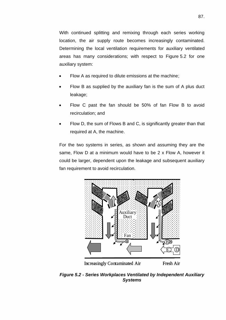
87.
With continued splitting and remixing through each series working
location, the air supply route becomes increasingly contaminated.
Determining the local ventilation requirements for auxiliary ventilated
areas has many considerations; with respect to Figure 5.2 for one
auxiliary system:
• Flow A as required to dilute emissions at the machine;
• Flow B as supplied by the auxiliary fan is the sum of A plus duct
leakage;
• Flow C past the fan should be 50% of fan Flow B to avoid
recirculation; and
• Flow D, the sum of Flows B and C, is significantly greater than that
required at A, the machine.
For the two systems in series, as shown and assuming they are the
same, Flow D at a minimum would have to be 2 x Flow A, however it
could be larger, dependent upon the leakage and subsequent auxiliary
fan requirement to avoid recirculation.
Figure 5.2 - Series Workplaces Ventilated by Independent Auxiliary Systems
Auxiliary Duct
Fan
A
B
C D
Fresh AirIncreasingly Contaminated Air
Auxiliary Duct
Fan
A
B
C D
Fresh AirIncreasingly Contaminated Air

88.
Figure 5.3 shows an alternate ventilation arrangement for the same
workplace. With this single fan and split duct arrangement the fan
delivery, Flow E, is much larger being the sum of the two vehicle
requirements, Flow A, and leakage en route to both delivery points.
The bypass requirement, to avoid recirculation, Flow F is also greater,
consequently Flow G leading up to the fan is larger than under the
previous arrangement.
Figure 5.3 - Series Workplaces Ventilated by Single Auxiliary System
Within these arrangements, limiting duct leakage, especially in long
systems, is critical as it factors into both the fan and bypass flow
requirements. The scenario presented in either Figure 5.2 or 5.3 can be
further complicated if the main haulage route providing the air to the
draw-point fans originates from yet another auxiliary system.
The preceding scenarios have focused on ventilation arrangements
within typical drifts. The size of the workspace such as in ‘room and pillar’
type mining adds yet another consideration.
Auxiliary Duct
Fan
A
E
F G
A
Auxiliary Duct
Fan
A
E
F G
A

89.
Figure 5.4 shows an auxiliary ventilated room. In this instance, although
the muck pile is ventilated with the appropriate volume, it is the total
clearance time of the room that can be an issue.
Figure 5.4 - Large Workspace Ventilated by Auxiliary Method
These considerations demonstrate how even at the local level it is
important to understand how the ventilation system operates and a
workers’ relationship to contaminated air. Provision of the appropriate
airflow does not guarantee the necessary dilution effect unless the
contaminants and airflow are managed correctly.
When developing a mine ventilation plan the following basic design
principles for auxiliary ventilation should be considered:
• For local ventilation (in individual work places) air should be
supplied in accordance with any regulatory standards. In most
instances, the air is injected into the workplace by means of a fan
from the main drift to the working face through a rigid or flexible
duct.
• To limit the air volume required at the fan, the duct sections should
be properly coupled to the fan and joined to each other, and the
whole system maintained to keep leakage to a minimum.
Auxiliary Duct
FanTo Ore
Pass
Fresh Air
Auxiliary Duct
FanTo Ore
Pass
Fresh Air

90.
• To limit the pressure needed from the fan, the duct should be as
smooth and as straight as possible, sections / fan coupled correctly,
and with the number of bends, elbows or changes in cross-sectional
area or profile reduced to a minimum.
• With respect to limiting duct resistance, rigid followed by flexible and
lastly spiral reinforced provide the least resistance. Where the
spiral type ducting is used, it should be extended to its full length.
The duct delivery must be close enough to and directed towards the
working face such that the discharge air velocity is sufficiently high
enough to produce the required air velocity.
• Where the duct discharge is subject to blast damage, it could be
replaced with a rigid section, the duct may be retracted along a
carrier wire to a safe distance, or the system turned off during the
blast. Where the duct is retracted, or fan system temporarily
stopped, it is necessary to ensure that the workplace is flushed prior
to re-entry.
• The duct discharge should never be pinched in an effort to increase
outlet air velocity at the expense of total volume. Nor should the
pipe be perforated here and there to deliver air all along the drift;
this takes necessary air away from the face area, where dilution of
contaminants is essential.
• The fan that serves the work place should operate independent of
the primary ventilation system. Often, a drawn steel grill, with
lozenge-shaped openings slightly over 2 cm in size, is used to
protect workers and the fan blades. This type of grill blocks off a
considerable portion of the fan intake area, provides considerable
resistance and reduces the volumetric performance of the fan.
Further, this size grill readily becomes clogged and further
increases the intake restriction. Ideally it would be preferable to
place the fan in a location where no grill is necessary; failing that,
the grill should have openings 4 to 6 cm in size.

91.
• The positioning of the fan in the main drift is by far one of the most
critical aspects. It should never be placed too close to the work
place entrance, or out of the general flow regime of the main drift,
or its purpose will be defeated because of recirculation of air (and
therefore contaminants) at the fan intake. The fan should be placed
more than 5 m upwind of the entrance and be facing in the direction
from which the non-contaminated air is coming. It should not be
placed within a cut-out along the wall unless sufficient fresh air is
guaranteed. Similarly, caution must also be taken close to bends
and junctions where fan placement could be in a stagnant area.
• In addition, the quantity of air flowing in the main drift must be
sufficient to supply the work place and maintain a positive flow past
the fan. Therefore, it is recommended that the flow in the main drift
must be 50% greater than that delivered by the fan, or recirculation
can occur at the fan intake, even if the intake is located away from
the entrance.
• In situations where the length of the auxiliary system changes with
time, such as development drifts and retreat mining, the duty of the
auxiliary system will have to be regularly reviewed to compensate
for changes in leakage and resistance. In association with this, the
flow supplied in the main drift will also require review to ensure the
integrity of the fresh air supply system.
• Long auxiliary installations can require multiple fans spaced along
the duct. Where flexible duct is employed, the final flow, after
leakage delivered by the initial fan to the second fan, must be
greater than its intake requirement to avoid recirculation.
• The use of an intake ‘bleed’ should be discouraged as the
compounding effect of recirculation in as few as a three fan series
system can dramatically deplete the amount of fresh air reaching
the final discharge. Rigid ducting is preferred for multiple fan
systems.
92.
• Finally, it is important to be fully familiar with the work place and the
demands of the production cycle so as to make the necessary
adjustments to reduce worker exposure. Well-informed workers
who understand the basic principles of mine ventilation can often
carry out these adjustments.
5.1.3 Ventilation design principles – coal mines
Main ventilation in coal mines is provided in a similar manner to hard rock
mines, although the main fans almost always exhaust. Auxiliary
ventilation systems consist of either brattice, used to divert airflow to the
working place or auxiliary fan and duct. Auxiliary ventilation is normally
exhaust using rigid ducts, although forcing overlap systems are used
occasionally.
• Bord and pillar operations
Bord and pillar operations are normally ventilated by brattice or auxiliary
ventilation. There are many configurations which can be used to ventilate
using brattice. An example is shown in Figure 5.5.
In this case, A and B Heading, 16-17 cut through (c/t) have been
completed and C Heading is being driven. Brattice is being used to
create an airflow in the C heading drive by exposing the outbye end of
the brattice to return ventilation pressure.
Subsidiary brattice sheets are used to divert airflow locally.
One of the hazards inherent in a brattice ventilated process is that small
adjustments to the brattice can cause changes to the amount of airflow
and therefore whether or not diesel access is permitted. For example,
removal of the partial brattice in D Heading, 16-16 c/t would cause a
reduction in the parallel E Heading, probably sufficient to make
E Heading inaccessible to diesel machinery.

93.
Figure 5.5 - Brattice Ventilated Bord and Pillar Operations
The use of auxiliary ventilation in bord and pillar is more arduous from an
operational perspective but provides more security of airflow. A
modification of the bord and pillar case is shown in Figure 5.6.
Advantages inherent in an auxiliary ventilation system include the
following:
• Increased robustness;
• Ventilation closer to the working face;
• Reduction in susceptibility to changes in ventilation;
• Elimination of series ventilation; and
• Ventilation to numerous places more readily achieved.
T pieces, bends and in line regulation are required in order to divert
airflow to the appropriate locations. The diagram shows a single auxiliary
fan. However, where numerous headings are ventilated, more than one
fan, possibly with more than one duct system would be used.
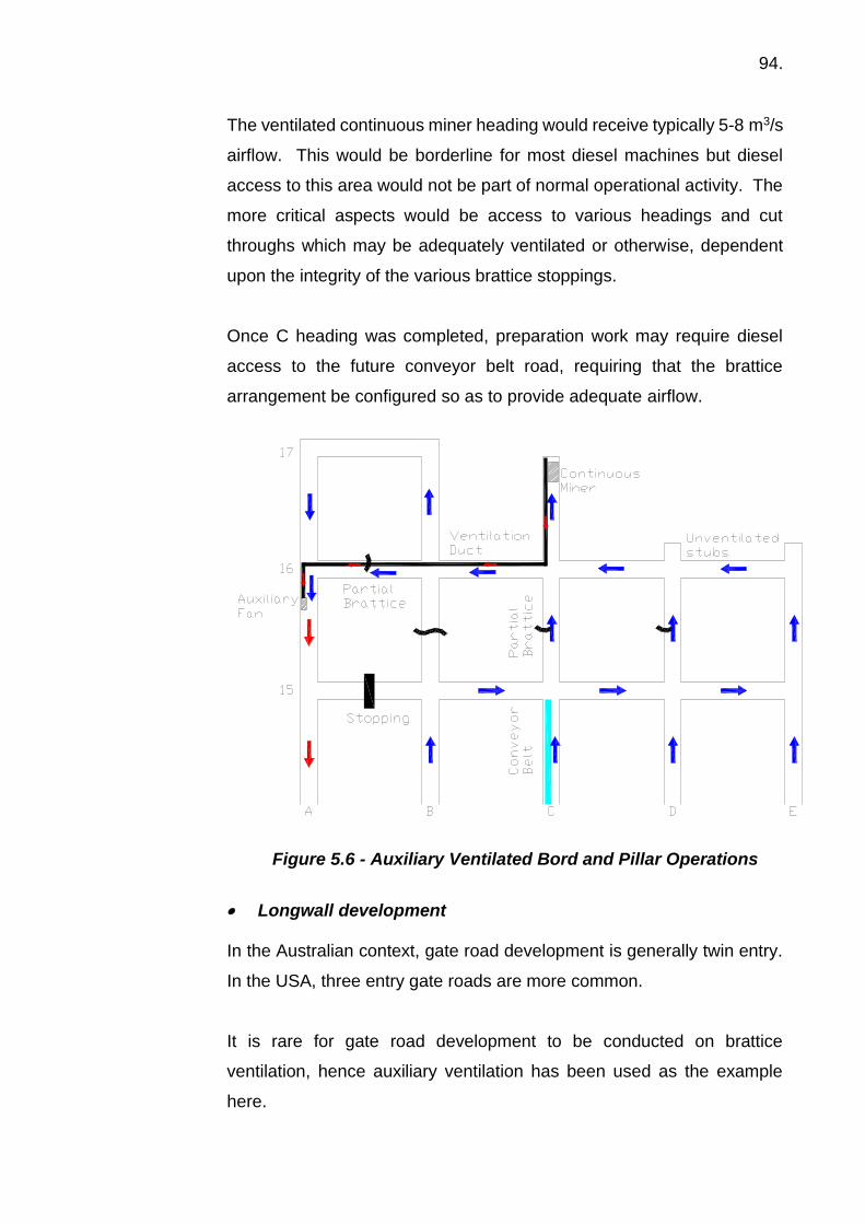
94.
The ventilated continuous miner heading would receive typically 5-8 m3/s
airflow. This would be borderline for most diesel machines but diesel
access to this area would not be part of normal operational activity. The
more critical aspects would be access to various headings and cut
throughs which may be adequately ventilated or otherwise, dependent
upon the integrity of the various brattice stoppings.
Once C heading was completed, preparation work may require diesel
access to the future conveyor belt road, requiring that the brattice
arrangement be configured so as to provide adequate airflow.
Figure 5.6 - Auxiliary Ventilated Bord and Pillar Operations
• Longwall development
In the Australian context, gate road development is generally twin entry.
In the USA, three entry gate roads are more common.
It is rare for gate road development to be conducted on brattice
ventilation, hence auxiliary ventilation has been used as the example
here.

95.
A gate road development would typically be ventilated by 25-50 m3/s at
the inbye end, meaning the order of 40-90 m3/s at the panel entry. This
would support more than three diesel machines in the worst case in the
main ventilation airflow.
In the development activity, it is not uncommon for preparation work to
take place in a pre-driven conveyor road entry whilst completion of
development of the adjacent transport road is conducted. This is shown
in Figure 5.7.
Figure 5.7 - Twin Heading Gate Road Development
In many cases, preparation work would be conducted in this situation,
cleaning up A Heading ready for a belt move. This would require
sufficient airflow in A Heading to support diesel activity and in B Heading
to support continuous miner operations.

96.
The capacity of auxiliary fans is increasing with time and multiple fans in
a single development is a common solution. Twin continuous miners in
a development panel is also common. In such a case, twin fans are
normally used, generally with twin, separate ventilation ducts, each
continuous miner being serviced by an individual auxiliary ventilation
system.
The ventilation capacity of an auxiliary fan and duct system is limited by
fan capacity and dust diameter. Provision of sufficient airflow both to the
development process and the completed heading can be challenging.
• Longwall operation
A typical U ventilation system is shown in Figure 5.8. The total airflow
entering the longwall split would typically range from 25 m3/s to as high
as 100 m3/s. Hence, the use of diesel equipment is normally catered for.
The single heading inbye of the longwall face, adjacent to the goaf, is
ventilated by a bleed system, a small diameter shaft to the surface or by
auxiliary ventilation. Provision of adequate airflow for diesel machinery
in this location can be difficult.
Figure 5.8 - Typical Longwall Ventilation System

97.
• Longwall recovery and installation
During longwall recovery, significant challenges exist with regard to the
use of diesels. Typically, the longwall face is caved as shields are
removed and this choking of the airway across the face leads to reduced
airflow.
Additionally, the longwall recovery process involves numerous diesel
machines and this compounds the problem of reduced available airflow.
Figure 5.9 - Longwall Recovery
5.1.4 Summary
Ventilation has been and will continue to be an important part of a mine’s
emissions control strategy. Historically it has been the primary method through
simple dilution; today combined engineering solutions are required as it would
be unrealistic to control all workplace contaminants purely with ventilation.

98.
5.2 Noise
Occupational noise-induced hearing loss (NIHL) has been described by many
as one of the biggest compensable diseases. The annual national
compensation cost is estimated to be over AU$30 million in Australia. The real
cost is probably ten times this.
The mining industry is a “high risk” industry and employees are often exposed
to high noise levels. Noise management should be a key component of any
risk management programme. Australia Standard AS/NZS 1269:2005
provides guidance on effective methods of managing workplace noise and
minimising noise induced hearing impairment, as does the NIOSH webpage
“Mining Topic: Hearing Loss Prevention Overview”.
5.2.1 Introduction
Noise is sound caused by a vibrating object. The vibrating object sets air
particles in motion and this motion causes sound pressure waves that are
detected by the human ear. Noise can be:
• Steady like the sound of a fan;
• Changing like traffic passing on the highway; or
• Impulsive like a hammer hitting a metal object.
Noise in the form of sound pressure may travel a long way from its origin before
it is registered by the human brain. It passes through air, solid matter, fluids
and nerves. The contact point on the human body for this process is of course
the ear.
The ear and auditory system is more complex than is generally believed.
It consists of four main parts: the external ear, the middle ear, the internal ear
and the central auditory pathways. The first two are relatively uncomplicated.

99.
The external ear consists of the auricle (or pinna - the part you can see and
scratch) and the external auditory canal. It is separated from the middle ear
by the drum membrane. The middle ear contains three little bones - malleus
(hammer), incus (anvil) and stapes (stirrup). These convey the sound into the
complicated mechanisms of the internal ear. They also have two small
muscles attached to them, which help protect the inner ear from loud sounds.
The internal ear includes two separate organs in charge of two main functions
of the ear: the cochlea (the auditory organ) and the vestibulum, the balance
organ.
If sound waves are followed from their source to the brain by hitting, for
example, a nail with a hammer, sound waves are generated and pass through
the air to the ear of the hearer. There they are received by the auricle and
funnelled into the auditory canal. They cause the eardrum to vibrate, and the
vibrations are transmitted through the three bones of the middle ear - from the
malleus, via the incus to the stapes - and on to a second membrane in the
internal ear called the “oval window”.
(Source: Coal Services Health & Safety Trust – reproduced with permission)
Figure 5.10 – Components of the Ear
Then the sound waves enter the winding passages of the cochlea, vibrating a
system of fluids, until they reach the central auditory system: the so-called
Corti’s organ in the centre of the cochlea.
In Corti’s organ there are thousands of sensory hair cells that respond to
individual frequencies.

100.
The sensory cells transform the sound waves to nerve impulses that are
transmitted by the auditory nerve to the central auditory pathways and the
brain. Finally then, the individual will perceive and hopefully understand that
they have heard something, the sound of a hammer hitting a nail, rather than
a thumb!
It’s the tiny sensory cells that are affected when individuals are exposed to
excessive noise. They can be damaged or disappear entirely - and they can
never be restored. NIHL is irreversible.
The intensity or loudness of noise is described by a unit called the decibel (dB).
The term was named in honour of Alexander Graham Bell, the inventor of the
telephone.
The amplitude or sound intensity scale used is from 0 to 140 dB. It is a special
logarithmic scale and therefore noise levels cannot be added or subtracted in
the normal arithmetic way. For example, add a 60 dB noise to another 60 dB
noise and you wind up with 63 dB, not 120 dB.
Another important characteristic of noise is frequency or pitch. Frequency is
the number of sound waves per second, measured in hertz (Hz). The higher
the frequency, the higher pitched the sound.
Since human ears respond to some frequencies more than others do, a
correction factor known as “A-weighting” is applied to the noise level (dB). The
result is dB(A).
For exposure to noise in the occupational environment, an eight-hour
equivalent continuous A-weighted sound pressure level, LAeq,8h, of 85 dB(A) is
a common standard. Safe Work Australia (2015), South American countries,
the ACGIH (2016) have this standard, while South Africa and countries in
Europe have similar level standards.
For 12-hour shifts this is reduced to 83 dB(A).

101.
For peak noise levels, the limit is 140 dB(C).
As a rule of thumb if two people are a metre apart in a workplace and have to
raise their voices to be heard or understood by each other, the noise levels are
most likely greater than 85 dB(A).
For every 3 dB(A) increase in noise level, a person’s exposure time must be
reduced by half; e.g. if the noise level rises to 88 dB(A) the maximum exposure
time should be not more than 4 hours, 91 dB(A) maximum exposure time is
2 hours, 94 dB(A) down to 1 hour, and so on.
For each 1 metre in distance a person is moved from the source of noise,
generally speaking, a reduction of 3 dB(A) in noise level is achieved for the
person.
Many hand-held tools (electrical grinders, saw, drills and air ratchets, air rattle
guns, air drills, air blower nozzles etc) can generate noise levels up to and in
excess of 120 dB(A) meaning, at 120 dB(A) the maximum exposure time for a
person should be no more than 6 seconds in any one eight hour period.
The exposure time to noise is also accumulative; i.e. each dose of noise on
each occasion within the same eight-hour period is added together.
The exposure time to noise is also affected when working in atmospheres
containing some organic vapours and other so-called ototoxins.
5.2.2 Health effects
Hearing ability or acuity is greatest during childhood. Typically, the range of
audible frequencies heard by a young person is from 20 to 20,000 Hz. (Dogs,
bats and dolphins on the other hand can detect much higher frequencies.) As
one ages however, the ability to hear the higher frequencies declines
somewhat. This effect, due to aging, is called presbycusis. It usually doesn’t

102.
become noticeable until the later years, when you can’t hear high frequency
sounds like a watch ticking or your children asking to borrow money.
If you are exposed to excessively loud noise levels for many years, you can
experience hearing losses above that due to aging. The damage cannot be
repaired. Hearing loss depends on how loud the noise is and the length of
time you are exposed.
When you are exposed to high levels of noise the sensory hairs in the cochlea
tire or become fatigued. The result is temporary hearing loss. Normal hearing
will return, after a period of 16-24 hours away from the noise. This is similar
to walking across a front lawn. The blades of grass lie down for a while but
will return to a normal position in a short time.
If continual or repeated noise exposure occurs, prolonged over-stimulation of
the hair cells will gradually injure or destroy them. This is the cause of
permanent hearing loss. This is similar to walking across the front lawn day
after day along the same path. Eventually the grass will be destroyed and,
likewise, hearing loss will be permanent.
At first, the higher frequency sounds disappear. This may go unnoticed at first,
but gradually lower and lower frequency sounds disappear. Think of removing
the highest tone musical instrument from an orchestra and then starting to
remove the lower toned instruments. Eventually it won’t sound like an
orchestra any more.
Once the hair cells are injured or destroyed, they cannot be repaired or
replaced. Hearing aids cannot repair the damage that has occurred. It is
irreversible.
Certain people exposed to high noise levels may complain of ringing or a
hollow buzzing in the ears (tinnitus). This may be a temporary or a permanent
problem.

103.
Impulse or impact noise is a momentary sharp noise that, if sufficiently loud,
can cause serious damage to hearing. Examples of equipment that cause
impulse noise are pile drivers, gunfire, explosive charges, etc.
Care must be exercised to ensure that the number of impacts per day (8 hours)
is maintained below appropriate limits.
In all cases, workers should never be exposed to impact noise levels in excess
of the national standard of 140 dB(C) peak SPL.
Prevention, by reducing the noise exposure via implementing mechanical or
administrative controls or using personal hearing protection, is the only way to
minimise NIHL.
Episodes of high noise occur in all mines however they need to be identified,
evaluated and appropriate steps taken to control them at their source, and/or
initiate a personal hearing protection programme.
This will undoubtedly take time and thus each site should develop and observe
a hearing conservation programme (see section 4.2). This will involve
evaluating noise exposures, monitoring employee exposure, assessing any
loss of hearing of individuals and the introduction of a range of control
strategies including hearing protection.
In assessing the possible loss of hearing, some reliance is placed upon the
screening audiometric test.
The object of the audiometric test is to determine the sound pressure levels
(or thresholds) at which you can just hear pure tone test frequencies. The tone
generator is called an audiometer. The audiogram is either a printout or graph
of hearing thresholds for each ear for each pure tone at varying intensities. It
is reviewed by the audiologist to determine whether or not your hearing has
changed.
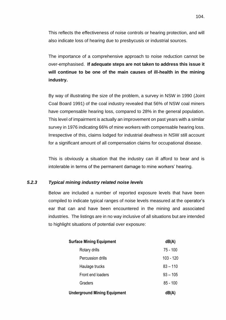
104.
This reflects the effectiveness of noise controls or hearing protection, and will
also indicate loss of hearing due to presbycusis or industrial sources.
The importance of a comprehensive approach to noise reduction cannot be
over-emphasised. If adequate steps are not taken to address this issue it
will continue to be one of the main causes of ill-health in the mining
industry.
By way of illustrating the size of the problem, a survey in NSW in 1990 (Joint
Coal Board 1991) of the coal industry revealed that 56% of NSW coal miners
have compensable hearing loss, compared to 28% in the general population.
This level of impairment is actually an improvement on past years with a similar
survey in 1976 indicating 66% of mine workers with compensable hearing loss.
Irrespective of this, claims lodged for industrial deafness in NSW still account
for a significant amount of all compensation claims for occupational disease.
This is obviously a situation that the industry can ill afford to bear and is
intolerable in terms of the permanent damage to mine workers’ hearing.
5.2.3 Typical mining industry related noise levels
Below are included a number of reported exposure levels that have been
compiled to indicate typical ranges of noise levels measured at the operator’s
ear that can and have been encountered in the mining and associated
industries. The listings are in no way inclusive of all situations but are intended
to highlight situations of potential over exposure:
Surface Mining Equipment dB(A)
Rotary drills 75 - 100
Percussion drills 103 - 120
Haulage trucks 83 – 110
Front end loaders 93 – 105
Graders 85 - 100
Underground Mining Equipment dB(A)

105.
Airleg & Jumbo drill 103 – 120
Continuous miner 93 – 110
Longwall shearers 90 – 105
Roof bolters 83 – 95
Haulage trucks 90 – 100
Ventilation fans 90 – 110
Processing Equipment dB(A)
Crushers 90 – 100
Autogenous grinders 90 – 100
Screen classifiers 90 – 103
Chutes and hoppers 100 – 110
General Maintenance Type Activities dB(A)
Screw gun / drill 86
Large hand power saw 87
Sledge hammer 90
Rattle gun 98
Chipping gun 103
Metal Fabrication dB(A)
Hammering on metal objects 115 – 120
Punch press 102 – 107
9-inch angle grinder 97 – 106
5.2.4 Very high and impact noise Air-arc cutting or air-arc gouging is a particular situation where very high noise
exposures occur in mining related industries.
Air-arc cutting is used for example to cut dragline or shovel buckets to remove
defective parts or to gouge out cracks found in the frames of draglines or
buckets. It is also used in the iron and steel industry to cut large, up to 40
tonnes pieces of steel scrap from the steelmaking processes into smaller sizes
that can be recycled and fed back into the steelmaking furnaces.

106.
A copper clad carbon rod is used to create an arc that generates enough heat
to melt the metal. Compressed air is used to remove the molten metal from
the cut. The noise is generated when the air disturbs the magnetic field
created by the arc which results in a very, very loud cracking sound.
In a Noise Identification Project (MSHA 2000) it was reported that the Sound
Pressure Level can be of the order of 108 – 120 dB(A). They also
acknowledged that a welder’s personal noise exposure depends upon the
amount of time spent gouging during the shift. The highest dose obtained
during this study was 483% for a 10-hour shift.
The study concluded that there are different product and method parameters
that can reduce noise related exposures.
Other examples in the mining industry where very high or very high impact
noise exposures occur include exploration drill rig contractors and geologists.
In a study by Kee (1996), he reported “daily noise dose received (DND) ranged
from 1 - 16 times the permissible limit, based upon an 85 dB(A) 8-hour Leq.
Impact noise of 115 dB(A) was consistently recorded for each drill operator
with occasional excursions to 140 dB(A). The geometric mean (GM) for 13
samples was 96.5 dB(A) and GSD of 6.3.”
Some typical high noise levels from other tools include:
Rotohammer 96 dB(A)
Rattle gun 98 dB(A)
Chipping gun 103 dB(A)
Other sources of high noise levels include drilling and roof bolting.
Sources of Peak or impact noise levels are associated with:
• Roof bolting – peaks up to 130 dB(C).
• Explosives - peaks up to 150dB(C)
107.
• Compressed air - peaks up to 120 dB(C) are not uncommon – need for
silenced nozzles.
• Pile driving – can go over limit of 140 dB(C). Sound proof cabins required.
As noise exposure in mining operations tends to be variable in intensity and
intermittent in duration, the only way to assess daily noise exposure in these
circumstances is by use of a personal noise dosimeter which integrates sound
level exposure over the course of the full shift and calculates the Daily Noise
Dose. A study performed at a Newcastle underground mine showed the face
workers were exposed to an average projected daily noise dose of 186% (Coal
Services H&S Trust 2008). This is the equivalent of a constant noise exposure
of 93 dB(A). Peak noise exposures during shifts ranged from 60 dB to 123 dB
for different workers.
5.3 Volatile organic vapours 5.3.1 Introduction
Organic vapours usually arise in the workplace as a result of the use of organic
solvents. Solvents have a wide application within industry because of two
characteristics:
• They dissolve a wide range of materials (which are often insoluble in
water); and
• They evaporate into the atmosphere easily.
It is this second characteristic that leads to many problems of exposure which
can be further exacerbated if the activity takes place in a poorly ventilated
space or involves heated or warm components. Organic solvents are found in
the mining industry in a broad range of products used in: conveyor belt
repairing; polyurethane resin injection during underground roof bolting; in
degreasers to cleaning products and paints; and solvent extraction processes
(e.g. Shellsol for copper recovery). The organic chemicals in these solvents,
and the sources for associated organic vapours in the atmosphere, include
hydrocarbons (xylene, toluene, mineral turps and white spirit), chlorinated
hydrocarbons typically used in cleaning type applications (trichloroethylene,

108.
perchloroethylene, 1,1,1 trichloroethane), ethanol and other alcohols, esters
(ethyl acetate), ketones (acetone, MEK) and isocyanates from the application
or use of polyurethane or two pack paint spraying. Where xanthates are used,
for example in the flotation process, carbon disulphide (CS2) can be given off
as a vapour and in mist.
The range and combinations of these types of chemicals that occur in
commercial products are endless, with reference to the SDS, being one way
of establishing what each product actually contains.
5.3.2 Health effects
The range of health effects resulting from excessive exposure to solvents and
their vapours is nearly as large as the number of solvents in use today.
In all cases the extent of any health effects is dependent on the duration and
frequency of exposure and the concentration in air of the substance involved.
Vapours of many organic solvents can be irritating to the respiratory tract, or
can affect specific organs of the body; e.g. liver (carbon tetrachloride), kidney
(trichloroethane), cardio vascular system (trichloroethylene, carbon
disulphide). In many cases severe damage can be done to the central nervous
system (brain and spinal cord), ranging from alcohol-like intoxication to
narcosis (stupor) and in some severe cases eventually death from respiratory
failure. Respiratory sensitisation (an asthma type condition) can result from
exposure to isocyanates.
Some specific organic solvents are either the cause of, or suspected of
involvement in, cancer. The best known compound in this category is benzene
and thus petrol (which contains up to 5% benzene) should never be used to
clean anything and only used as a fuel.
These types of compounds are the basis for many of the cases of skin
disorders found within the mining workforce. Skin contact often causes drying,

109.
cracking, reddening and blistering in the affected area. This condition is
commonly referred to as dermatitis.
It is also possible for solvents to be absorbed through the skin. They can cause
eye irritation, although permanent eye damage is rare.
Detailed toxicological descriptions of the many organic solvents and their
vapours likely to be experienced at mine sites are beyond the scope of this
module, however the following general guidance is provided for their effective
management:
• Identify which solvents are on-site and assess the risks associated with
their use;
• Keep all employee exposures as low as is reasonably practicable by
appropriate control measures including changing to less volatile solvents
where possible;
• Always ensure adequate ventilation is available;
• Do not spray solvents (thus producing much more vapour and aerosol) if
brushing, dipping or rolling is possible;
• Do not apply to heated surfaces;
• Eliminate the use of solvents if possible (e.g. use water-based paints if
this is practical);
• Do not use solvents in confined spaces without taking adequate
precautions (e.g. ventilation, breathing apparatus, workplace
monitoring); and
• Be extremely careful when cleaning out sludges which may contain
solvents (degreasing tank sludge) as movement of the sludge may
release large concentrations of organic vapours.
One other aspect of organic solvents that should be noted is the potential for
the production of extremely dangerous compounds in the event of a fire or
exposure to excessive heat. For instance, chlorinated hydrocarbons can

110.
produce phosgene in the presence of a welding arc. Thus, any metal products
cleaned with these types of products should be allowed to dry before welding.
This is only one example of this aspect, and caution should be exercised when
using solvents near ignition sources, both from an explosion and toxic vapour
perspective.
More detailed information can be found on the NIOSH webpage “Organic
Solvents”.
5.3.3 Exposure levels
The review of health risks in rubber belt splicers by Haynes (2008) indicated
that exposure levels vary considerably due to how a particular task was
undertaken. It is not possible to provide typical values due to the high
variability that can occur.
5.3.4 Typical constituents of splicing compounds
Table 5.1 shows a list of chemical substances, their main chemical
constituents and their use in rubber belt splicing and repair.
Table 5.1 – Typical Splicing Compounds
(Source: Haynes, A. (2008))
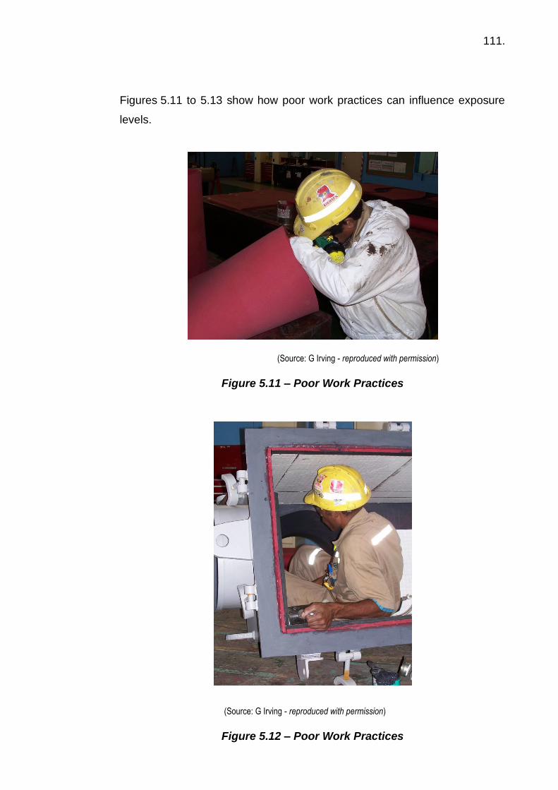
111.
Figures 5.11 to 5.13 show how poor work practices can influence exposure
levels.
(Source: G Irving - reproduced with permission)
Figure 5.11 – Poor Work Practices
(Source: G Irving - reproduced with permission)
Figure 5.12 – Poor Work Practices

112.
(Source: R Crafter (2004) - reproduced with permission)
Figure 5.13 – Poor Work Practices
Spray painting with two pack paints and injection of polyurethane resins
containing isocyanates in the mining industry are areas of potential respiratory
sensitisation that need consideration. Spraying of two pack isocyanate
containing paints must be carried out wearing air supplied respirators and
attention paid to other workers in the area.
Spraying of isocyanate paints is covered by OH&S Regulations in most
jurisdictions and information is typically available from state authorities.
5.4 Vibration (whole body & hand arm)
Vibration can be defined as oscillatory motions of solid bodies and can be
visualised as waves on a lake. Vibration can be either:
• Whole-body; or
• Segmental (such as hand/arm or foot/leg).

113.
Vibration energy can be passed onto operators from vibrating tools, vibrating
machinery or vibrating work areas and may give rise to adverse health effects.
The magnitude of these will depend on the severity and length of exposures.
5.4.1 Health effects Vibration can induce a number of adverse health effects. For whole-body
vibration (WBV) these may include:
• Degenerative changes in the spine.
• Problems in the digestive system.
• Problems for pregnant workers.
• Impairment of vision and/or balance.
For segmental and hand-arm vibration (HAV) these may include:
• The development of circulation problems in the fingers (Raynaud’s
Syndrome or vibration induced white finger) especially when combined
with cold conditions.
• Nerve degeneration.
• Pressure on nerves passing through the carpal tunnel at the wrist giving
rise to numbness and tingling in the fingers especially at night.
• Tenosynovitis (inflammation and pain in the tendons around the wrist or
foot).
• Muscle degeneration in the arms or legs.
Older age and smoking have been significantly linked to the onset of vibration
induced white finger.
In addition to these long-term effects, short-term exposure can lead to fatigue
and loss of dexterity when performing tasks. In Britain, Vibration White Finger
has emerged as a major compensable health issue in retired coal miners.

114.
WBV should be assessed using a recognised standard (e.g. ISO 2631-1:1997
& AS 2670-2001). A typical whole-body vibration measurement system is
shown in Figure 5.14.
(Source: Coal Services Health & Safety Trust – reproduced with permission)
Figure 5.14 - Typical Whole- Body Vibration Measurement System
A vibration sensor is placed on the seat to pick up the vibrations being
transmitted through to the body – driver, operator or passengers. The sensor
detects the vibration in the three axes. The vibration signal is then analysed
and logged by a meter. Further analysis can be performed after downloading
the data to a computer. The rms vibration, measured in m/s2, is assessed
against the criteria shown in Figure 5.15.
Using this Standard, most rides measured in open-cut and underground coal
mines exceed the recommended exposures for an eight-hour shift. In some
very rough rides (usually in vehicles without suspension) recommended
exposure times were well below any reasonable work or travelling time periods
(4 or 5 minutes or less).

115.
(Source: Coal Services Health & Safety Trust – reproduced with permission)
Figure 5.15 - Australian Standard Health Guidance Zones (as per ISO 2631)
The Vibration Dose Value (VDV), measured in m/s1.75, is also used in the
assessment of WBV. This is a measure of dose and will progressively increase
across an exposure period. The VDV formulae uses
the rms Acceleration raised to the fourth power and is more sensitive to the
peaks in the acceleration levels which reflect the jolts and jars which can be
prevalent in mining vehicles. These peaks are thought to be important when
assessing the risk of WBV. The formula is
The European Parliament has a Directive on workplace WBV and HAV
exposure, imposing minimum requirements of a daily exposure limit or action
value (standardised to an 8-hour reference period) of:
• A limit of 1.15 m/s2 and an action value of 0.5 m/s2 for WBV; or
• A vibration dose value (VDV) limit of 21 m/s1.75 and an action value of
9.1 m/s1.75 for WBV; and
• A limit of 5.0 m/s2 and an action value of 2.5 m/s2 for HAV.

116.
The determination of potential impact of vibration is not straight forward and
requires expert assistance. It may often be most practical to conduct
assessments using known vibration levels of equipment or tools;
manufacturers should be able to supply such information. The UK HSE
provide good resources for qualitative assessment of “Vibration at Work”.
5.4.2 Control of vibration The control of vibration in mining relies on both engineering design and
administrative procedures. For example, to reduce WBV while driving or
operating in mines the following aspects should be considered:
Engineering design
• Effective vehicle suspension or isolation of the cab from the frame of the
machine.
• Seat design including effective seat suspension (seat must not bottom
out).
• Vehicle maintenance including appropriate seat maintenance and timely
seat replacement.
• Sufficient cab space especially leg and headroom.
• Careful layout of controls and displays.
• Fully adjustable controls and seating.
• Passengers to face forward in appropriately designed seats.
• Good visibility from the cab especially at night.
• Appropriate and effective road maintenance systems.
• Appropriate tyres and tyre pressures.
Administrative measures
• Defining and giving feedback on what ‘operating to conditions’ means in
practice (appropriate speeds and skills).
• Specific vehicle operator training.
117.
• Job rotation – operation of different vehicles each shift.
• Regular, frequent breaks out of the seat (a minimum of 5 minutes within
each hour; preferably 10 minutes within each hour especially where 12-
hour shifts are worked.
Control of segmental vibration should include:
• Education on the effects of exposure to vibration and how to minimise
these.
• Engineering design to damp vibration (e.g. handles of tools).
• Isolation of the hands or feet from the vibration source – note that anti-
vibration gloves do not work.
• Maintaining warm hands while using vibrating equipment.
Vibration inside structures (e.g. coal preparation plants) needs to be assessed
and may require structural modification. Alternatively, isolation of operators
may be appropriate along with a range of other techniques (i.e. use of damping
materials, sandwich structures etc).
Checklist for vibration exposure reduction An extensive checklist has been provided in the Second Edition of “A
Handbook on Whole-Body Vibration in Mining” (McPhee, Foster & Long 2009).
The check list is to help identify and manage vibration problems at the mine.
Photocopy the check list, date it and use it to provide an overview of the current
situation. Progressive checklists can be completed as problems are identified
and solutions implemented.
The checklist includes headings for:
• Identification of vibration sources.
• Measurement, assessment and recording of vibration levels.
• Reducing vibration exposures:
- Operator training;

118.
- Road maintenance programmes;
- Restricting speeds;
- Design of vehicles and suspension;
- Cab design and layout;
- Seat design, suspension and layout;
- Maintenance of vehicle suspension systems;
- Lighting and visibility;
- Task design and work organisation; and
- Shot firing standards.
• Monitoring and evaluation.
• General comments.
5.5 Spontaneous combustion
Spontaneous combustion, also termed sponcom, can be defined as the
outbreak of fire without application of heat from an external source.
Spontaneous combustion can occur in all types of mines where the required
conditions occur. Historically coal mines have been prone to spontaneous
combustion both within coal seams but more commonly in waste material.
The issue of spontaneous combustion in relation to coal seams has challenged
the minds of scientists for centuries. Dr Plott, Professor of Chemistry at
Oxford, published, in 1686, the first known paper on spontaneous combustion
of coal. Many theories have been put forward since that time, but a basic set
of criteria must exist before spontaneous combustion can occur. These
criteria, first outlined in 1914, are:
a) The coal must react (chemically or physically) with another substance.
b) The reaction must be accompanied by the production of heat; i.e. be
exothermic.
c) The rate of heat production must be greater than the rate at which heat
can be dissipated from the coal.
d) The above conditions must be satisfied at the prevailing ambient
temperature and pressure.

119.
There are many publications on spontaneous combustion that should be
sourced if such an issue is likely to occur on-site. However, as this Student
Manual is focused on occupational hygiene issues associated with mining,
discussion is restricted to those long-term health issues likely to arise from
spontaneous combustion incidents.
In terms of health effects, spontaneous combustion results in oxidation of coal
(and coal waste) causing the release of large volumes of noxious and
flammable gases that can cause asphyxiation, poisoning, or explosions if a
source of ignition is present. The main toxic gases likely to be present as the
result of spontaneous combustion are carbon monoxide, carbon dioxide,
hydrogen sulphide, oxides of nitrogen and sulphur dioxide. The range of
flammable gases evolved includes hydrogen, methane, ethane, ethylene,
acetylene and a complex mixture of other hydrocarbons.
In recent years some focus has been placed on this hydrocarbon mixture. As
with all combustion, some potentially dangerous aromatic hydrocarbons
(Polycyclic Aromatic Hydrocarbons - PAHs) have been shown to be present in
the gas streams of combusting coal.
Exposure to high concentrations of these compounds for a significant period
(years), may result in lung cancer. Most of this concern is based on the
experience of coke oven workers where lung cancer in the past has been a
serious problem and significantly higher concentrations of PAHs may occur.
More recent research has demonstrated the possibility of spontaneous
combustion releasing compounds that may play a role in skin cancer. Given
this, it is important that caution is exercised when breathing the atmosphere in
the vicinity of a spontaneous combustion heating, because of the presence of
not only acutely toxic compounds such as carbon monoxide, but also the
possibility of the presence of PAHs in significant concentrations. Moreover,
care should be exercised when cleaning up after a sponcom event to ensure
no tars, etc come in contact with the skin, producing skin disorders such as
erythema (reddening of skin).

120.
In the metalliferous mining industry, most spontaneous combustion fires can
be traced to the presence of high sulphide-containing ores.
With sulphide based ores, the process of spontaneous combustion arises from
the oxidation of the metal sulphide to the oxide with the generation of heat and
toxic gases such as sulphur dioxide and some hydrogen sulphide.
Dust clouds from sulphide ores can also explode if an ignition source is
present, much in the same manner as coal dusts, however the energy is less
thus giving rise to a less violent explosion.
The management of spontaneous combustion is best managed by the isolation
of the reactive material from oxygen. In coal waste dumps this is usually done
by placing the reactive materials within thick non-reactive layers (e.g. clay) of
covering material which prevent the movement of oxygen.
5.6 Hazards of overburden removal
Historically there has been a view within the mining industry that the focus
should only be on the ore body.
In terms of health issues, such a narrow focus can result in workers being
exposed to levels of contaminants which can give rise to serious adverse
health effects.
Some common issues that arise during overburden removal include:
Dust – Both respirable and inhalable dust can be a problem, especially if the
stripping of overburden is done with dozers, etc with open cabins.
Silica – It is very common for dusts arising from overburden removal to contain
crystalline silica. In some parts of the world this can be up to 35% (w/w) but
concentrations of 5% are very common.
121.
Spontaneous combustion – The removal of overburden exposes underlying
material to oxygen which in some circumstances results in spontaneous
combustion. The issues associated with spontaneous combustion have been
discussed in Section 5.5.
Asbestiform minerals – Depending on the geological structure of the region,
it is possible to uncover bands of asbestiform materials during overburden
material removal. The Pilbara region of Western Australia is well known for
this problem, which requires appropriate management.
5.7 Diesel emissions 5.7.1 Introduction
Diesel exhaust emissions have given rise to increased anxiety in mines in
respect to adverse health effects ever since diesel equipment was introduced
in the early 1950’s. As a result of this anxiety, numerous research projects
have taken place in the United States, Canada, Europe and Australia. Some
of these research projects have focused on the effect of exposure to diesel
exhaust emissions while others have concentrated on understanding the
composition of diesel exhaust emissions and developing appropriate control
technologies.
A complete review of the literature relating to diesel exhaust emissions is
beyond the scope of this Manual, but a summary of the main issues is provided
in this section. More detailed information on diesel particulate can be found in
the Australian Institute of Occupational Hygienists’ publication on diesel
particulate (AIOH 2004).
5.7.2 Composition of diesel exhaust fumes
Diesel exhaust has been shown to contain thousands of gaseous and
particulate substances, some of which are known to exhibit some form of
biological activity. While the major gaseous components found in air (nitrogen,
oxygen, argon, carbon dioxide, water vapour) comprise approximately
99 percent of the mass of diesel exhaust, much smaller quantities of other
gases and vapours such as carbon monoxide, nitric oxide, nitrogen dioxide,

122.
sulphur dioxide and hydrocarbons are also present. This complex mixture is
in a continual state of flux because a normally aspirated diesel engine draws
in a constant charge of air, and various load conditions are met by changes in
the quantity of fuel injected into this air and ignited in the combustion chamber.
Therefore, the composition of exhaust gas from a diesel engine changes
constantly as the fuel / air ratio is altered to meet variable demands for power.
Particulate matter is also found in the exhaust of diesel engines. Diesel
particulate matter is a complex mixture of compounds composed of non-
volatile carbon, large numbers of different adsorbed or condensed
hydrocarbons, sulphates and trace quantities of metallic compounds.
Over recent years attention has focused on diesel particulate matter for a
number of reasons. Firstly, research has shown that diesel particulate matter
is almost entirely respirable, with about 90 percent by mass having an
equivalent aerodynamic diameter of less than 1.0 µm. This means that the
particles can penetrate to the deep regions of the lungs, where, if retained,
there is a possibility that they may participate in some form of biological activity.
The role of elemental carbon (the central carbon core) in diesel particulate has
gained significant prominence in relation to possible adverse health effects and
is the focus of regulatory attention in many countries.
Emissions have been shown to be influenced by such factors as engine type,
duty cycle, fuel quality, engine maintenance, intake ambient conditions,
operator work practices and emission controls.
Because of this variability it is difficult to define a typical diesel exhaust,
however it is clear they do contain some compounds which require appropriate
control procedures to minimise worker exposures. These compounds include:
• Carbon monoxide
• Oxides of nitrogen
• Sulphur dioxide
• Aldehydes
• Hydrocarbons

123.
• Diesel particulate
Whilst at elevated exposures these all can produce adverse health effects, the following
section will focus on diesel particulate.
5.7.3 Health effects of diesel particulate (DP)
The potential for adverse health effects in humans arising from excessive
exposure to diesel particulate has been the subject of intense scientific debate
for many years and due to areas of uncertainty may well be for many more.
Notwithstanding this debate, there is sufficient evidence to suggest diesel
particulate from traditional ‘old’ (prior to 1970) diesel engines is a carcinogen
and thus various regulatory authorities around the world have moved to control
employee exposure to this contaminant.
Since 1957, many epidemiological studies have been reported in the literature
where the prevalence of lung cancers in workers has been evaluated in
respect to exposure to diesel particulate matter. Many of these studies have
been discounted due to issues with study design, but in 1955 the US based
Health Effects Institute (an industry-government funded organisation)
reviewed 30 such studies and concluded the data was consistent in showing
weak associations between increased risk of lung cancer and exposure to
diesel exhaust.
In 2012, the International Agency for Research on Cancer (IARC) classified
diesel exhaust as a human carcinogen (Group 1). This decision was primarily
based on the findings of the Diesel Exhaust in Miners Study (DEMS), which
has been criticised by a number of researchers.
An expert panel set up by the Health Effects Institute to evaluate the DEMS
results, together with a large study in the trucking industry, concluded that both
studies provided a useful basis for quantitative risk assessments of diesel
exhaust exposure. However, the results of both studies were non-definitive as
the studies suffer from several methodological shortcomings.

124.
At this point in time most overseas regulators are focussing on EC as the
measure of workplace exposure to diesel particulate. Research is ongoing
with respect to particle size and total surface area.
In recent years greater focus has been placed upon the non-malignant health
aspects associated with exposure to diesel particulate. Perhaps the most
definitive statement on this aspect was made in 2002 when the EPA concluded
that:
i) Exposure to diesel emissions (including particulate) may give rise to eye,
throat and bronchial irritation, light headedness, nausea, cough and
phlegm.
ii) Based on animal evidence the potential existed for chronic respiratory
disease.
Other research has suggested that the irritant effect of exposure to diesel
emissions which has traditionally been attributed to aldehydes in fact arises
from the fine diesel particulate which impacts the mucus membranes causing
a local irritant effect and at high concentrations a stinging sensation and
lachrymation (eye-watering).
In summary, it is reasonable to state based on the totality of the scientific
literature, most informed professionals would recognise that diesel particulate
from ‘old’ diesel engines is a carcinogen. With the evolution of cleaner diesel
engines and use of lower sulphur fuels, the composition of diesel particulate
from the newer technology has consequently changed substantially with EC
dropping from about 70% by mass in emissions from older engines to as low
as 13 to 16% in emissions from the newer technology diesel engines.
As an agreed well-defined dose response relationship between exposure and
health outcomes currently does not exist there is little doubt that this area will
be the subject of further research and debate.
Given the current state of knowledge there is sufficient evidence to indicate
that an 8-hour time weighted average (TWA) exposure standard of 0.1 mg/m3
125.
(measured as elemental carbon), with a 0.05 mg/m3 action level triggering the
need for controls and health surveillance, should provide adequate protection
against irritant effects and also minimise any risk of lung cancer.
5.7.4 Control of emissions
Considerable research has been conducted throughout the world on specific
measures to control diesel emissions in the mining industry.
A comprehensive overview of the topic is provided in an AIOH (2004)
publication. This publication can be obtained through the AIOH website at
https://www.aioh.org.au/onlinestore/publications (accessed 10 April 2017). In
summary, the hierarchy of controls must be utilised when determining the
appropriate controls to be utilised; for example:
• elimination of diesel equipment through the use of alternative powered
equipment, where feasible (e.g. electrical);
• provision of low emission diesel engines and fuel;
• provision of air conditioned (filtered) operators’ cabins;
• exhaust ventilation;
• good engine maintenance;
• use of exhaust filtration systems;
• administrative controls (e.g. limits on overtime and tag boards);
• worker education and training; and
• use of appropriate respiratory protection.
It should be understood that more than one control strategy will likely be
required to reduce worker exposures to as low as is reasonably practicable.
Whatever strategy is adopted it should be under-pinned by an effective
maintenance programme so that emission reductions are sustained.
5.8 NORM in ores
5.8.1 Background Naturally occurring radioactive materials (NORM) are ubiquitous in the
environment. NORM is widespread in sands, clays, soils and rocks, and many
ores and minerals, commodities, products by-products and recycled residues.

126.
Although the concentration of NORM in most natural substances is low, any
operation in which material is extracted from the earth and processed can
potentially concentrate NORM in products, by-products or waste (residue)
streams. The generation of products, by-products, residues and wastes
containing NORM has potential to lead to exposures to both workers and
members of the public along with environmental impacts.
The radionuclides of interest include long lived radionuclides such as uranium-
238 (238U) and thorium-232 (232Th) and their radioactive decay products (such
as isotopes of radium, radon, polonium, bismuth and lead), and individual long-
lived radionuclides such as potassium-40 (40K), rubidium-87 (87Rb) and
indium-115 (115In).
It is sufficient to say here that these radionuclides are present principally in the
solid form (including airborne dusts) with the exception of radon which is a gas.
The principle radiations are:
• Alpha – α;
• Beta – β; and
• Gamma – γ.
The organ(s) principally at risk include:
• Lung;
• Kidney;
• Skeleton;
• Liver;
• Colon; and
• Bone.
Some of the industries where radiation protection issues may arise in dealing
with NORM include:
• Bauxite / aluminium industry;
• Phosphate industry;

127.
• Metal extraction and processing;
• Coal extraction and electricity generation;
• Iron and steel production;
• Mineral sands and rare earths;
• Downstream processing of mineral sands; and
• Oil and gas industry.
5.8.2 Radiation protection series As an example, the Australian Radiation Protection Series is published by the
Australian Radiation Protection and Nuclear Safety Agency (ARPANSA) to
promote practices that protect human health and the environment from the
possible harmful effects of radiation.
There are four categories in the Series:
• Radiation Protection Standards which set the fundamental requirements
for safety;
• Codes of Practice contain practice-specific requirements that must be
satisfied to ensure an acceptable level of safety when dealing with
exposure to radiation;
• Recommendations provide guidance on fundamental principles for
radiation protection; and
• Safety Guides provide practice-specific guidance on achieving the
requirements set out in Radiation Protection Standards and Codes of
Practice.
There are currently 22 publications in the series and can be downloaded
from the ARPANSA website at:
http://www.arpansa.gov.au/Publications/codes/rps.cfm (accessed April 2017).
Numerous publications on radiation safety are also available from the
International Atomic Energy Agency (IAEA) website: http://www-
pub.iaea.org/books/IAEABooks/Series/33/Safety-Standards-Series
(accessed 27 July 2017).
128.
There are two specific publications by ARPANSA pertaining to the mining
industry that need to be acknowledged and distinguished between:
1. “Safety Guide for the Management of Naturally Occurring Radioactive
Material (NORM)” (ARPANSA 2008) and refers to situations where the
radionuclides present have little or no commercial value. This will be
discussed, albeit briefly; and
2. “Code of Practice and Safety Guide for Radiation Protection and
Radioactive Waste Management in Mining & and Mineral Processing”
(ARPANSA 2005) where uranium ores are mined specifically for their
radionuclide content.
The IAEA publications “Occupational Radiation Protection in the Mining and
Processing of Raw Materials” and “Management of Radioactive Waste from
the Mining and Milling of Ores” are also relevant.
5.8.3 Summary of safety guide for NORM (ARPANSA 2008) The Safety Guide discusses the issues involved in consideration of risks
associated with naturally-occurring radioactive material (NORM). It does not
discuss uranium mining and processing or mineral sand extraction as they are
dealt with in existing regulatory frameworks.
The extraction and processing of mineral ores containing low levels of
naturally-occurring radionuclides can lead to the generation of products, by-
products, wastes and residues containing elevated concentrations of these
radionuclides. There is also considerable variability in quantities of material
and radionuclide concentrations within and between industries. Potential
exposures from NORM can occur in a wide range of industries and for a wide
range of materials.
A short description of known industries where NORM may arise is given in
Section 2. The long half-lives of some of the radionuclides means that
radionuclide concentrations in NORM tend to decrease only slowly with time.
These features mean that management of NORM is a long-term issue, and it

129.
is important that operators acknowledge that it is their responsibility to
understand and manage the NORM issues relevant for their industry. These
issues include radiological protection during extraction, processing, transport,
storage and disposal of NORM.
Section 3 describes the radiological issues associated with NORM
management. In general, the activity concentrations in NORM are low. This
means that in many cases, regulation is unlikely to be necessary. Guidance
for both regulators and operators is given on assessing the need for regulation,
including consideration of unconditional or conditional exemption, which could
be appropriate in many NORM situations.
In particular, guidance is given on the need for a graded approach to
regulation, which places emphasis on the need for optimisation of protection.
The costs and benefits of introducing a regulatory approach need to be
considered and compared with those for other options that would achieve the
same objective.
Implementation of a NORM Management Plan, including characterisation of
materials, monitoring of radionuclide concentrations, and ongoing risk / dose
assessment is an important management tool, whether or not regulation is
applied. The main features of a NORM Management Plan are described.
Section 5 deals with operational issues, giving guidance on characterisation of
materials, identification of potential risks, risk assessment and risk mitigation.
Guidance on remediation of legacy sites (sites contaminated as a result of past
operations) is given in Section 6. In particular, guidance is given on the use of
computer models as an aid to planning and assessing alternative remediation
strategies.
Public perception is important in any issue involving radioactive materials.
Involvement of stakeholders is therefore an important consideration when
assessing the optimisation of protection when utilising NORM, or disposing of

130.
NORM residues and wastes. There is a clear need for communication of the
potential risks and benefits associated with proposals of this nature.
Relating the normally low risks from NORM exposure to other risk factors
understood by the public (e.g. road accidents, heart attacks) may be useful.
There is growing interest in utilising NORM residues because of the difficulties
associated with long-term storage and/or disposal, as a consequence of the
large volumes of material involved. Many of the residues are generated in
large quantities (e.g. megatons per year). Potential uses include incorporation
in landfill, road fill and building materials. In considering potential disposal
options for NORM, there is a need for careful assessment of radiological risks.
Guidance on a framework for such assessments is provided.
This Safety Guide currently incorporates three Annexes giving detailed
information on the oil and gas, bauxite / aluminium and phosphate industries.
It is anticipated that further Annexes will be developed in future on other
industries dealing with NORM.
5.9 Intrinsic safety of equipment
5.9.1 Introduction
The intrinsic safety (IS) of equipment is an issue that hygienists must
understand and comply with for those mines that have such restrictions. It is
of utmost importance that all equipment meet the required standard and that
the IS rating of a device not be compromised by inappropriate maintenance or
repairs. The following provides an overview of the IS rating system.
5.9.2 International Electrotechnical Commission scheme The International Electrotechnical Commission Scheme for standards relating
equipment for use in explosive atmospheres is known as IECEx.
Across the world there has been a general move towards the adoption of
IECEx Standards and in particular the 60079 Series for gases and vapours
and the 61241 Series for dusts by the different Standard setting organisations

131.
including those from Europe, United Kingdom, South Africa, USA, Canada,
Asia and Australia and New Zealand.
The modern day automation of industry has meant an increased need to use
equipment in Explosive or Ex areas. Such equipment is termed “Ex
equipment” and is found in areas such as:
• Automotive re-fuelling stations or petrol stations;
• Oil refineries, rigs and processing plants;
• Chemical processing plants;
• Printing industries, paper and textiles;
• Hospital operating theatres;
• Aircraft re-fuelling and hangars;
• Surface coating industries;
• Underground coal mines;
• Sewerage treatment plants;
• Gas pipelines and distribution centres;
• Grain handling and storage;
• Woodworking areas;
• Sugar refineries;
• Metal surface grinding, especially aluminium dusts and particles; and
• Solvent extraction plants.
An explosion can only take place if the following three factors are present:
• A flammable substance;
• Oxygen; and
• An ignition source.
An explosion only occurs if the substance-air mixture lies within a certain
concentration range – the explosive limits.
5.9.3 Explosion protection
The hierarchy for explosion protection are:

132.
• Reduce or avoid the use of flammable substances;
• Do not allow any releases of flammable substances to form potentially
explosive atmospheres;
• Remove sources of ignition from the potentially explosive atmosphere;
• Use adequately designed equipment that reduces the probability of
causing an explosion; and
• Provide measure to reduce the effects of explosions.
Guidance is provided in the IECEx Standards to enable the choice of suitable
equipment based on the following processes.
a) Classifications of zones
It is necessary to firstly identify the likelihood of an explosive atmosphere
being present.
The explosive atmosphere may be caused by the presence of a
flammable liquid, gas or vapour or by the presence of combustible dust
in suspension or layers or a combination of dust and gas explosive
atmospheres.
Gases, Vapours, Mists
Dusts
Explosive Atmosphere is Present
Zone 0 Zone 20 Most of the time
Zone 1 Zone 21 Some time
Zone 2 Zone 22 Seldom or short term
(Source: TestSafe – reproduced with permission)
The area may also be classified as a “Safe Area” if the explosive material
or air is not expected to be available in quantities that would allow it to be
explosive.
133.
b) Explosion groups
When the zone classification takes place, the explosive materials are
examined and the explosion protected electrical equipment is divided into
two groups depending on where it is used:
I equipment used in underground mining – explosive materials being
mainly methane and coal dust; and
II equipment used in other hazardous areas; i.e. other industries with
additional subgroups for Group II according to the nature of the
explosive gas atmosphere for which is intended:
IIA – least readily ignited gases such as propane and benzene
IIB – more readily ignited gases such as ethylene and diethyl
ether
IIC – most readily ignited gases such as hydrogen and
acetylene.
c) Temperature classes
To prevent the hot surfaces of electrical equipment from creating ignition,
the maximum surface temperature of electrical equipment exposed to
gas must not exceed the ignition temperature of gases that may be in the
area.
Group I electrical equipment requires the temperature of the components
and surfaces exposed to dust and methane to be limited to less than
150°C. In case the components and surfaces are protected from the
ingress of dust, the maximum temperature of such components may be
higher, but must be less than 450°C.
For Group II electrical apparatus the maximum surface temperature must
not exceed the values in Table 5.2, which corresponds to the
temperature class of the equipment. For convenience, a temperature
class may be assigned to a gas or vapour based on its ignition
temperature.

134.
Table 5.2 – Maximum Surface Temperature / Ignition Temperature
Temp Class
Maximum Permissible Surface Temp of the Equipment (°C)
T1 450
T2 300
T3 200
T4 135
T5 100
T6 85
(Source: TestSafe – reproduced with permission)
5.9.4 Levels of protection and zones of application Intrinsic Safety has 3 levels of protection:
“ia” – means that the type of protection ‘intrinsic safety” (no release of spark
energy or thermal energy that can cause ignition) is maintained with
up to two faults.
“ib” – means intrinsic safety is maintained with up to one fault.
“ic” – means intrinsic safety is maintained, but no requirement to apply
faults.
Level of Protection Suitable for
“ia” Zones 0, 20
“ib” Zones 1, 21
“ic” Zones 2, 22
(Source: TestSafe – reproduced with permission)
Safety factors are applied and the equipment evaluated for spark and thermal
ignition energy after the application of faults.

135.
In areas where explosive atmospheres can occur despite the explosive
protective measures employed, only explosive protected equipment can be
used.
Explosive protective equipment can be manufactured to IEC protection type
levels which are subject to the requirements of their own specific standards.
Intrinsic safety, Flameproof, Increased Safety, Encapsulation etc are some of
the common types of protection used for explosion protected electrical
equipment.
5.9.5 The Ex marking label Only appropriate certified and marked electrical equipment may be used in
hazardous areas. Users of electrical equipment must ensure that the
equipment complies with the relevant regulations and local standards.
The information of the name of the manufacturer, model number, Ex code and
certificate number is attached to the equipment.
An example is:
Smith Electronics
Model TRE
Ex ia IIC T4
Cert 098X
Serial No 8765
“ia” equipment is suitable for zone 0 application
IIC the equipment is suitable for Groups IIA, IIB, IIC
T4 the equipment is suitable for gases with auto ignition temperature greater
than 135°C.
Further and much more detailed information for the use of gas detection
equipment in potentially explosive atmospheres including the Classification of
Zones, Explosion Groups, Temperature Classes, the Types of Protection
136.
provided by equipment, the requirements for Certification and Marking is
available from the different National Standards and Certification bodies.
5.10 Tunnelling 5.10.1 Introduction
Tunnels may be driven for mining, hydroelectric projects, sewage disposal
schemes, oil storage, atomic power stations, road and rail traffic, diversion of
water, irrigation schemes etc. Tunnels can vary in length from a few metres
to many kilometres and in cross section from about 1 m2 to over 100 m2.
Tunnels are dug in various types of material, from soft clay, sand to hard rock
and the method of excavation depends on the ground condition and can
include use of:
• Cut & cover.
• Explosives.
• Full face tunnel boring machines for hard or hard to medium ground.
• Shield machines for soft, loose running sands and silts.
• Grouting.
• Concreting.
• Cryogenic treatment.
• Earth balancing machines etc.
The obvious occupational hygiene hazards (rather than safety type issues)
include:
• Noise and vibration.
• Dust – both inhalable and respirable quartz.
• Diesel particulate.
• Grouting type chemicals.
• Confined spaces.
• Heat stress.

137.
5.10.2 Respirable quartz Exposure to high levels of respirable quartz in tunnel operations is not
uncommon and the following levels were indicated at the Australian
Underground Construction and Tunnelling Association Safety Seminar in
2001.
Activity Respirable Quartz (mg/m3)
Road header 0.5 - 10
Truck driver 0.2 – 1.5
Outbye section of tunnel 0.1 – 0.8
NB: Exposure standard for respirable quartz is 0.1 mg/m3
Some of these levels are considerably in excess of the exposure standards
and often the means of control by ventilation or use of water sprays are not
sufficient, hence there is a reliance on respiratory protection.
However, all too often the levels of protection afforded by the selected
respirator are not sufficient for the exposure levels experienced.
5.10.3 Typical tunnelling operations
Figures 5.16 and 5.17 are typical of tunnelling operations and highlight the
potential of worker exposure to silica containing dusts.

138.
(Source: A Rowe – reproduced with permission)
Figure 5.16 – Tunnelling Operation
(Source: A Rowe – reproduced with permission)
Figure 5.17 – Tunnelling Operation
5.11 Silicosis Crystalline silica is one of the most abundant minerals in the earth’s crust and
thus is commonly encountered in the mining and processing of many minerals.

139.
There are three forms of crystalline silica – quartz, cristobalite and tridymite.
Quartz is by far the most common form of crystalline silica and one of the most
significant occupational health hazards encountered in the minerals industry.
The primary health risk is from the inhalation of respirable silica dust, which
may result in silicosis and other occupational lung diseases. In more recent
years, inhalation of respirable crystalline silica has been identified as a risk
factor in the development of lung cancer.
There are three types of silicosis that may develop from the inhalation of dusts
containing respirable crystalline silica. There are:
• Classic silicosis (chronic silicosis);
• Accelerated silicosis; and
• Acute silicosis.
Once these conditions develop there is no known cure, no reversal of the
condition and in some cases the pulmonary effects can become more severe
after exposure has ceased.
Classic (chronic) silicosis is the most common form and presents as fibrotic
changes in the air exchange region of the lung. These fibrotic changes
increasingly affect the lung’s ability to exchange gases, resulting in cardio
vascular stress and increased respiratory infections. Classic silicosis may take
10 – 30 years to develop.
Accelerated silicosis is the result of exposure to high concentrations of
respirable crystalline silica and commonly presents in periods of the order of 5
to 10 years from time of exposure.
Acute silicosis results from the inhalation of massive levels of respirable
crystalline silica and presents in the lungs as a filling of the air spaces by fluids
and cells. Respiratory failure can occur over a period of several months with
the rapid onset of death due to the lack of oxygenation of blood.

140.
In 1996 IARC classified respirable crystalline silica from occupational sources
as a human lung carcinogen. The pathway of causation of lung cancer from
exposure to respirable crystalline silica is unclear, however there is
considerable evidence to demonstrate that persons with silicosis are at a much
greater risk of developing lung cancer.
What is important to remember is that all silicosis is preventable – no exposure
to respirable crystalline silica – no silicosis. There are many well developed
control strategies to achieve this goal and each operation needs to develop an
appropriate control strategy and ensure it is implemented and maintained.
Regular workplace monitoring for atmospheric respirable crystalline silica are
a measure of the effectiveness of the strategy and occupational exposure
limits (OELs) should be achieved under all operating conditions.
Where exposure to respirable crystalline silica presents a high level of risk to
workers, appropriate medical screening (chest x-ray and spirometry) should
be implemented.

141.
6. SPECIFIC ISSUES ASSOCIATED WITH MINERAL PROCESSING
6.1 Introduction
It has been seen earlier that there are a number of the specific occupational
hygiene issues associated with mining and as the extracted material is further
processed some of the same issues can reoccur but additionally there can be
new issues associated with primary and secondary beneficiation. The range
of potential exposures is therefore extensive. Figure 6.1 illustrates the main
elements of both the mining and mineral process and how they influence the
types of hazard found.
(Source: ICMM – reproduced under terms of copyright)
Figure 6.1 - Illustrative Flowchart for a Mining Operation
An overview of mining and mineral processes was presented in Section 2. In
the primary and secondary beneficiation processes for production and refining
of metals there is a series of physico-chemical reactions. These processes

142.
can be divided into crushing and milling (or sizing), hydrometallurgical, molten
salt and pyrometallurgical techniques.
6.2 Hazards from mineral processing The hazards from mineral processing are obviously mixed and varied. Heat,
gases, dusts, fumes, noise, vibration and the various chemicals used form a
complex exposure background in the working environment.
Gases containing sulphur dioxide, hydrogen sulphide, carbon monoxide,
hydrogen fluoride, and metallic fumes such as lead, mercury and cadmium and
dusts containing metals such as arsenic can be encountered depending on the
particular industry.
While routine exposure levels of the contaminants are generally under control
there are circumstances where the levels may be in excess of or massively in
excess of TWA exposure standards or even peak or ceiling exposure
standards.
Plant shutdowns, general maintenance operations, start-ups and malfunction
of the process are situations where high levels of exposure are particularly
likely to arise.
6.3 Beneficiation of hazards Although the concentration of NORM and trace metals in most substances is
generally low, almost any operation in which any material is extracted from the
earth and processed can concentrate NORM or trace metals in product, by-
product, residue or waste streams. An example of the beneficiation of hazards
from NORM occurs in the processing of mineral sands (ARPANSA 2008).
Rutile and synthetic rutile (from ilmenite) are processed to produce titanium
dioxide pigments for use in manufacture of paint, plastics, paper, ink and many
other products. Titanium oxide is extracted from rutile and synthetic rutile
using either a chloride process or by sulphuric acid extraction.

143.
The original rutile and synthetic rutile material contain trace quantities of
uranium and thorium and their radioactive decay products.
These radionuclides tend to follow the solid waste stream during processing.
Titanium oxide pigments do not have detectable levels of radioactivity, but the
solid waste does. Typical radionuclide concentrations in the solid waste are
provided below:
In a similar manner, the presence of low concentrations of trace metals in the
ore can consequently present concerns after the beneficiation process, as
illustrated by the following example.
A copper, gold and silver mine was known by the geologist to contain 200 ppm
of arsenic (As) in the ore. During ore processing it was present as a solid in
solution together with the copper. It was beneficiated with the copper in the
float cells and this was known to the metallurgist.
The concentration of the arsenic was now 5,000 ppm in a 50% slurry that was
transferred by pipeline to the Port for shipping overseas.
At the port, it was dewatered (no point in transporting water) and this is where
the problem surfaced.
Spilled liquid on the ground from the dewatering process both dries out and is
also tracked to nearby areas where it too dries out and subsequently becomes
airborne by both the wind and by the passage of vehicles and people.

144.
It was dusty (5 mg/m3 of inhalable dust), but the issue was this dust contained
arsenic of the order of 0.05 mg/m3.
Arsenic has an exposure standard of 0.01 mg/m3. Thus, it is possible to have
overexposures at dust levels below the inhalable dust standard of 10 mg/m3.
You need to know and understand the whole process.
6.4 Specific metals and minerals
6.4.1 Aluminium Extraction of aluminium metal takes place in three main stages:
1 Mining of bauxite ore;
2 Refining of the ore to recover alumina; and
3 Smelting alumina to produce aluminium.
• Mining Bauxite is mined by surface methods (open cut mining) in which the
topsoil overburden is removed by bulldozers and scrapers. The
underlying bauxite is mined by front end loaders, power shovels or
hydraulic excavators. Sometimes the bauxite is crushed and washed to
remove some of the clay and sand waste and then dried in rotary kilns.
Other bauxites may be just crushed or dried. The bauxite is then
transferred by various means (e.g. trucks, conveyors, ships) to refineries.
• Refining In almost all commercial operations, alumina is extracted from the
bauxite by the Bayer refining process, which consists of four stages:
1. Digestion – in which finely ground bauxite is fed into a steam heated
digester. Here it is mixed, under pressure, with a hot solution of
caustic soda.

145.
The aluminium oxide of the bauxite and some of the silica react with
the caustic forming a solution of sodium aluminate or green liquor
and a precipitate of sodium aluminium silicate.
2. Clarification - in which the green liquor or alumina-bearing solution
is separated from the waste (the undissolved iron oxides and silica
which were part of the original bauxite and now make up the sand
and red mud waste). This stage involves three steps: firstly, the
coarse sand-sized waste is removed and washed to recover caustic
soda; secondly, the red mud is separated out; and, thirdly the
remaining green liquor is pumped through filters to remove any
residual impurities. The sand and mud are pumped together to
residue lakes and the green liquor is pumped to heat exchangers
where it is cooled from 1000°C to around 650 -790°C.
3. Precipitation - in this stage the alumina is precipitated from the
liquor as crystals of alumina hydrate. To do this, the green liquor
solution is mixed in tall precipitator vessels with small amounts of
fine crystalline alumina, which stimulates the precipitation of solid
alumina hydrate, as the solution cools. When completed the solid
alumina hydrate is passed on to the next stage and the remaining
liquor, which contains caustic soda and some alumina, goes back
to the digesters.
4. Calcination - in the final stage the alumina hydrate is washed to
remove any remaining liquor and then dried. Finally, it is heated to
about 1000°C to drive off the water of crystallisation, leaving the
alumina, which is a dry, pure white, sandy material. A portion of the
alumina may be left in the hydrate form or further processed for the
chemical industry.
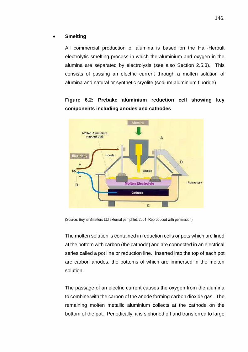
146.
• Smelting
All commercial production of alumina is based on the Hall-Heroult
electrolytic smelting process in which the aluminium and oxygen in the
alumina are separated by electrolysis (see also Section 2.5.3). This
consists of passing an electric current through a molten solution of
alumina and natural or synthetic cryolite (sodium aluminium fluoride).
Figure 6.2: Prebake aluminium reduction cell showing key
components including anodes and cathodes
(Source: Boyne Smelters Ltd external pamphlet, 2001. Reproduced with permission)
The molten solution is contained in reduction cells or pots which are lined
at the bottom with carbon (the cathode) and are connected in an electrical
series called a pot line or reduction line. Inserted into the top of each pot
are carbon anodes, the bottoms of which are immersed in the molten
solution.
The passage of an electric current causes the oxygen from the alumina
to combine with the carbon of the anode forming carbon dioxide gas. The
remaining molten metallic aluminium collects at the cathode on the
bottom of the pot. Periodically, it is siphoned off and transferred to large

147.
holding furnaces. Impurities are removed, alloying elements added and
the molten aluminium is cast into ingots, billets or slabs.
The smelting process is a continuous one. As the alumina content of the
cryolite bath is reduced more is added. Heat generated by the passage
of the electric current maintains the cryolite bath in its molten state so
that it will dissolve the alumina. A great amount of energy is consumed
during the smelting process; from 14,000 - 16,000 kilowatt hours of
electrical energy is needed to produce one tonne of aluminium from
about two tonnes of alumina.
The cathode is generally made from Soderberg paste, a mixture of tar
and anthracite coal, and releases coal tar pitch. Fluoride and some
Sulphur dioxide emissions occur from the pot.
Aluminium metal is produced in various shapes and sizes depending on
their end use. They may be rolled into plate, sheet, foil, bars or rods.
They may be drawn into wire which is stranded into cable for electrical
transmission lines. Presses extrude the ingots into hundreds of different
useful and decorative forms or fabricating plants may convert them into
large structural shapes.
A number of factors in the aluminium production cycle relate to the
environment and considerable resources are allocated to minimise the
impact of mining, refining and smelting on the surrounding environment.
Mine rehabilitation is carried out, making every effort to return the area to
at least its original condition. Extreme care is taken also with the handling
and disposal of red mud from the refineries. This is usually pumped into
dams which are sealed with impervious material to prevent pollution of
the surrounding countryside. Strict measures are taken also to minimise
fluoride emissions from smelters and dusty or corrosive material from the
refineries.

148.
Some of the occupational hygiene issues associated with the aluminium
industry include:
Dusts
- Alumina (Al2O3)
- Cryolite (Na3Al3F6)
- Aluminium fluoride (AlF6)
- Coke
- Lithium carbonate
Gases
- Sulphur dioxide (SO2)
- Hydrofluoric acid (HF)
Coal tar pitch volatiles (PAHs)
Heat stress
Noise and vibration
Alumina refinery workers may also be exposed to mercury when
undertaking maintenance, particularly in non-condensable vapour
systems in the digestion section of the process where exposure may be
to mercury vapour in off gases and mercury metal found condensed in
elbows, joints and in the bottom of vessels. The mercury is concentrated
from trace quantities in bauxite during the beneficiation process.
6.4.2 Lead / Zinc Most lead-zinc mines are underground operations and are highly mechanised.
Ore is drilled and blasted in large volumes, transferred to underground rock
crushers by large loaders and trucks before being hoisted to the surface in
skips or driven directly to the surface by truck via a spiral access tunnel
(decline). At the surface, the ore is subjected to additional crushing and fine
grinding.

149.
A flotation process separates the lead, zinc and other valuable sulphide
minerals from the waste rock particles (tailings) to form a concentrate.
Ground ore, water and special chemicals are mixed together and constantly
agitated in banks of flotation cells. Air is blown through the mixture in each
cell and the fine lead and zinc sulphide particles stick to the bubbles, which
rise to form a froth on the surface of the flotation cell. The tailings sink and are
removed from the bottom of the cell. The froth is skimmed off and the resulting
lead / zinc sulphide concentrate is dried. During this process, the ore, which
may contain only 5% lead, is upgraded to a concentrate with about 50% lead.
Lead and zinc can be produced pyrometallurgically or hydrometallurgically,
depending on the type of ore used as a charge. Only the former method is
described here, relevant to lead only.
The concentrate is sintered (partly melted) to combine the fine particles into
lumps and to remove some sulphur as sulphur dioxide. The sintered product
is then smelted in a blast furnace to produce impure lead metal (97% lead).
The lead metal is cooled in stages but kept molten to cause trace copper and
impurities to separate as a dross (impurities) at the surface layer. At each
cooling stage the dross layer is removed to be recycled to the blast furnace or
further processed. The remaining molten crude lead is either passed direct to
the refining stage or cast into lead bullion ingots for later refining.
Refining (purifying) the crude lead or bullion involves remelting then blowing
the molten lead with air to form a slag (impurities) layer containing antimony,
arsenic and some lead. Silver, and any trace gold or copper, is removed and
the refined lead (more than 99.9% lead) is cast into ingots (blocks) for use in
the manufacturing industry.
Some of the occupational hygiene issues associated with the lead industry
include:
Dusts
- Lead, zinc & quartz

150.
- Trace elements e.g. Cadmium & Arsenic
Metal fumes e.g. Lead, Cadmium, Arsenic & Mercury
Gases - Sulphur dioxide
Heat stress
Noise and vibration
6.4.3 Gold
• Mining Most gold production comes from open-cut mines. Large capacity earth-
moving equipment is used to remove waste rock from above the ore body
and then to mine the ore. Waste and ore are blasted to break them into
sizes suitable for handling and transport to waste dumps or, in the case
of the ore, to the crusher.
Underground mining is used where the depth of ore below the surface
makes open-cut mining uneconomic. Vertical shafts and declines (spiral
tunnels) are used to move people and equipment into and out of the mine,
to provide ventilation and for hauling the waste rock and ore to the
surface.
Deep extensions of deposits mined by open pit methods may be mined
later by underground methods beneath the old open pit.
• Processing
Coarse gold may be removed by gravity concentration. The processing
required to recover fine gold from crushed ore is determined by the free-
milling or refractory nature of the ore. Free-milling ore is ore from which
gold can be recovered by crushing, grinding and cyanidation (treatment
with a dilute cyanide solution) without additional processing. Free-milling
oxide ores are suitable for direct cyanidation of the crushed and ground
ore.

151.
In refractory ore, gold is locked in the sulphide minerals so that, to
achieve satisfactory levels of gold recovery, additional processing such
as roasting or biological leaching is required before cyanidation.
Sulphide minerals in refractory ores are converted to oxides by either
roasting or biological leaching to release the gold. In biological leaching
the oxidation is caused by the action of specific bacteria on the ore. The
tonnage of refractory ore to be roasted or leached is greatly reduced by
first producing a finely ground concentrate.
Ground ore or treated concentrate is placed in a weak solution of sodium
cyanide, which dissolves gold and forms a slurry of gold-bearing solution
and barren solids. Some ores may be treated by heap-leaching. This
involves sprinkling a weak cyanide solution over an open pile of ore
stacked on an impervious base. The solution percolates through the ore,
leaching gold as it goes, and is drawn off at the base before being treated
to recover the gold.
In both cases, the gold is recovered from the gold-bearing solution in a
process in which pellets of activated carbon made from charred coconut
husks are added to the slurry and the gold-bearing ions are adsorbed
onto the pellet surface. The pellet load is moved through a number of
linked tanks containing slurry in a direction opposite to the slurry
movement.
The pellets loaded with gold are removed and the gold is stripped from
them by washing in a solution of hot cyanide. The carbon used in the
process is recycled and an electric current is passed through the new
solution, depositing the gold on a steel wool cathode. The gold laden
cathode is treated with hydrochloric acid to dissolve any residual steel
and the gold sludge is filtered and dried, ready for smelting. At this stage
the gold-bearing material may contain silver and base metals. Where
mercury is present, it is removed by heating in a retort and recovered to
avoid environmental contamination.

152.
Gold is smelted in a crucible furnace to produce unrefined bullion. In
smelting, base metal impurities are oxidised and absorbed, leaving the
precious metals to be poured into ingot moulds. Smelted gold is then
refined.
• Refining
Several refining processes are used - chlorination, electrolytic and aqua
regia.
1. In the chlorination process (Miller process), chlorine is introduced
to melted bullion in a crucible furnace. The gas reacts with silver
and any remaining base metals to form chlorides, bubbles of which
rise to the surface of the molten bullion and are removed. The
molten, refined gold is then cast into bars.
2. The electrolytic process (Wohlwill process) involves dissolving gold
from the bullion (anode) in a chloride solution and redepositing the
gold on a pure gold or titanium cathode. Silver remains on the
anode. The cathodes are melted and cast.
3. In the third process, the unrefined bullion is dissolved in aqua regia
and silver is precipitated as silver chloride. Sulphur dioxide gas is
passed through the remaining solution and gold is precipitated as a
fine metallic powder. The gold is then melted and cast.
Some of the occupational hygiene issues associated with the gold
industry include:
Dusts
- Ore dusts, including quartz
- Sodium cyanide (NaCN)
Gases - Cyanide (HCN)
Heat stress

153.
Noise and vibration
6.4.4 Copper
• Mining
Large copper deposits are mined by either open-cut methods or from
underground mines in many of the major producing countries.
Figure 6.3 – Open-cut Copper Mine
(Source: R. Di Corleto – reproduced with permission)
• Processing At some mines, the copper is leached from the ore to produce a copper-
rich solution which is later treated to recover the copper metal. The ore
is first broken and set out on leach pads where it is dissolved by a
sulphuric acid solution to leach out the copper. The copper-rich solution
is then pumped to the solvent extraction plant to separate the copper as
a copper complex. This is concentrated and the solution is passed to the

154.
electrowinning plant to recover the copper. The copper cathodes
produced by electrowinning contain 99.99% copper which is suitable for
electrical uses.
The traditional method used at most mines involves the ore being broken
and brought to the surface for crushing.
The ore is then ground finely before the copper-bearing sulphide minerals
are concentrated by a flotation process which separates the grains of ore
mineral from the waste material, or gangue. Depending on the type of
copper bearing minerals in the ore and the treatment processes used,
the concentrate can contain between 25 and 57% copper. The
concentrate is then processed in a smelter.
Various methods of smelting are used to convert the concentrates to
copper metal. One method is to melt them with fluxes in a smelter
furnace to produce copper matte, which is a mixture mainly of iron and
copper sulphides usually containing 50 to 70% copper. The molten matte
is poured into a converter, which contains more fluxes, and converted
into blister copper, which is about 98 to 99% pure. The blister copper is
tapped, further refined in an anode furnace and finally electrolytically
refined to pure cathode copper.
Another process is where the concentrate is flash-smelted directly to
blister copper. In this process copper concentrate is fed into the smelter
with oxygen-enriched air. The fine concentrate reacts or 'flashes'
instantaneously as the sulphur fraction of the copper sulphides is burnt
and becomes sulphur dioxide gas. Molten copper and slag fall to the
hearth of the smelter. The slag forms a layer on the surface of the molten
blister copper. The blister copper is removed periodically for further
purifying in an anode furnace and electrolytically refined.
Some of the occupational hygiene issues associated with the copper
industry include:
155.
Dusts
- Copper (Cu) & quartz
- Trace elements (e.g. Arsenic)
Sulphuric acid mist
Fumes - Copper, Arsenic
Gases - Sulphur dioxide
Heat stress
Noise and vibration
6.4.5 Nickel
• Mining
Most nickel production is from nickel sulphide deposits, which are mined
by underground and open-cut methods, as are nickel laterite deposits.
• Concentration
After mining, the sulphide ores are transported to a concentrator to
upgrade their nickel content. The ores are first crushed and ground,
liberating the sulphide minerals from worthless rock, or gangue. The
sulphide minerals are then separated from the gangue, by flotation, and
dried.
• Smelting and refining
A nickel smelter, which incorporates an Outokumpu flash furnace,
produces nickel matte (essentially a mixture of nickel and iron sulphides),
usually containing 71-72% nickel and 5-6% copper. The nickel matte is
produced in granulated form and is used as feed to a refinery.
The refining process often uses a hydrometallurgical ammonia leach
process. The nickel is leached from nickel matte by ammonia under

156.
pressure. The resulting nickel-bearing solution is treated with hydrogen
sulphide to remove copper as copper sulphide and then with hydrogen
gas under pressure to precipitate metallic nickel. Nickel and cobalt left
in solution are finally precipitated by hydrogen sulphide as a mixed
sulphide product. The remaining solution is rich in ammonium sulphate,
which is crystallised for use as a fertiliser. Nickel powder is dried and
sold as such, or after compaction and heating as sintered briquettes.
Another refining process is that used for lateritic nickel ore. The ore is
dried, ground, reduced and leached with ammonia. Nickel is precipitated
as nickel carbonate, which is further treated to give a sinter of nickel and
nickel oxide containing 85%, 88%, 98% or 99.5% nickel. An ammoniacal
solvent extraction plant assists in the separation of higher quality nickel
and cobalt products.
Some of the occupational hygiene issues associated with the nickel
industry include:
Dusts - Nickel especially Ni sub-sulphide & quartz
Strong acid aerosols
Fumes - Nickel
Gases - Sulphur dioxide
Heat stress
Noise and vibration
6.4.6 Coal mining In open-cut mining, rock covering the coal seam (the overburden) is blasted
and removed by large draglines and/or electric or hydraulic shovels and trucks.
Modern equipment and techniques allow open-cut mines to be operated to
depths much greater than the 60 metres that was considered a maximum
depth for many years. Advanced methods used include where the upper

157.
section of overburden is removed by bucket wheel excavator followed by a
truck and shovel operation, which removes more overburden before the
deeper overburden is stripped by dragline.
Underground coal mining is often done by either the bord and pillar or the
longwall method (see Section 2.4). Generally, longwall techniques result in
higher productivity and higher recovery of coal than does the bord and pillar
method.
Black coal may be used without any processing other than crushing and
screening to reduce the rock to a useable and consistent size. However, it is
often washed to remove pieces of rock or mineral which may be present. This
reduces ash and improves overall quality. Washing involves immersing the
crushed coal in a liquid of high specific gravity in which coal floats and can be
recovered while the heavier rock and minerals sink.
Some of the occupational hygiene issues associated with coal mining include:
Respirable coal dust
Respirable quartz
Inhalable dust
- Coal dust
- Dust from shotcreting
- Roadway dusting (application of limestone for explosion mitigation) 20 to
>100 mg/m3 can regularly be experienced
Organic vapours
Diesel exhaust
Heat stress
Noise and vibration
158.
6.5 Acid and other processing chemical mists
Mists are very fine airborne droplets produced by atomization or condensation
processes. Sulphuric acid mist is most commonly produced as a result of
hydrolysis of water in electrolysis processes in metal refining, electroplating
and pickling, lead-acid battery production. It is also generated during the
manufacture of fertilisers.
Mists may also be generated during the mixing and agitation of acid or other
liquid baths and dissolution of solids in liquids.
• Electrolytic refining of metals
Airborne acid mists and droplets are generated by transfer of materials
from tank to tank and from the electrolysis process releasing bubbles of
oxygen into the air which also disperses the acid mist.
• Electroplating and pickling
Electroplating is the coating of a metal object with another metal using an
electrical current passing through a chemical solution. Metals used in
coatings include zinc, copper, brass, chromium, nickel, gold, cadmium
and lead.
Bubbles of hydrogen are released during the electrolysis process and
contained or ventilated can result in the generation of mists.
Pickling is a descaling process by which oxides (e.g. rust) and scale are
chemically removed from a metallic surface by immersion in a dilute
inorganic acid – generally sulphuric or hydrochloric acid.
The amount of acid splashing, gas evolution and mist formation are
largely dependent on the pickling process being used:
• Stationary or vat pickling;
• Batch pickling; or
• Continuous picking.
159.
• Control strategies
Various control strategies have been used to limit the amount of acid mist
in the atmosphere inside chemical processing plants. These include:
• Push-pull ventilation systems (small scale facilities);
• Inert gas blankets;
• Use of a chemical additive that acts as a mist suppressant;
• The use of plastic balls floating on top of the cell to inhibit the acid
from forming a mist. This is called “choffle” in some countries; and
• Enclosure of cells with exhaust ventilation.
6.6 Fixed radiation gauges 6.6.1 Introduction
Fixed radiation gauges are designed for installation as a fixed component
within an industrial process and are used for the direct or indirect control of
any part of that process.
The term “fixed radiation gauge” refers to the whole of the device and includes
the radiation source (radioactive material, energised X-ray tube or neutron
generator tube), source containment (radioactive source container, X-ray tube
housing or shielded enclosure or neutron generator tube housing or shielded
enclosure), associated exposure controls and detector.
In most countries, the ionising radiation sources used in fixed radiation gauges
are regulated by radiation control legislation in the various levels of
government. Industrial gauges, which include sources of ionising radiation,
are used for a variety of manufacturing process and quality control
applications. These applications may include non-invasive measurement and
control of:
• Thickness;
• Level;

160.
• Density;
• Weight;
• Composition (e.g. in stream analysis); or
• Moisture content.
In each of the applications, the principle of the operation of the gauge depends
on the detection of radiation that is transmitted through, scattered by or emitted
as a secondary emission from the item or material of interest.
If the radiation sources used in these gauges are not adequately shielded the
dose rates near them could constitute a significant hazard to health to people
working near them.
ARPANSA, IAEA and ICRP provide good guidance on the promotion of
practices that protect human health and the environment from the possible
harmful effects of radiation. The ARPANSA publication “Code of Practice &
and Safety Guide for the Safe Use of Fixed Radiation Gauges” is relevant to
further discussion, as an example, but good information on radiation gauges
is also available from:
• http://www-ns.iaea.org/tech-areas/communication-
networks/orpnet/documents/Nuclear-Gauges.pdf (accessed 27 July 2017);
and
• https://www.iaea.org/sites/default/files/sealedradsource1013.pdf
(accessed 27 July 2017).
6.6.2 Safe use of fixed radiation gauges
It is considered to be beyond the scope of this course to go into any great detail
of the Code of Practice and the accompanying Safety Guide for the safe use
of fixed radiation gauges (ARPANSA 2007), but a brief description of the topics
covered is provided below.
The purpose of this Code is to establish working practices, procedures and
protective measures and to ensure the security of radioactive sources. This
will ensure that the dose limits specified are not exceeded.

161.
In brief, most codes of practice or guidance will provide the requirements for
the design, testing, supply, use, storage, transport, disposal and radiation
monitoring of fixed radiation gauges. For example, these may include:
• Responsibilities of the
- Supplier of a fixed radiation gauge
- Responsible person
- Service provider
- Employee
• Management of radiation incidents
• Radiation monitoring devices and radiation levels
• Transport of radioactive material
• Repairs and disposal.
Most codes are supported by a number of guides such as documents which
may include a Radiation Management Plan. The Radiation Management Plan
specifies what must be included in relation to:
• Work practices; and
• Roles and responsibilities; and
• Radiation monitoring requirements; and
• Control of an incident involving a gauge; and
• Storage of the gauge; and
• Transport of the gauge; and
• Records of repairs and maintenance of the gauge; and
• What to do with the gauge (e.g. sale, transfer, disposal) when it is no
longer required; and
• Records and accountability; and
• Mechanisms for implementation and review, including the arrangements
for the provision of expert advice in radiation protection, of the Radiation
Management Plan; and
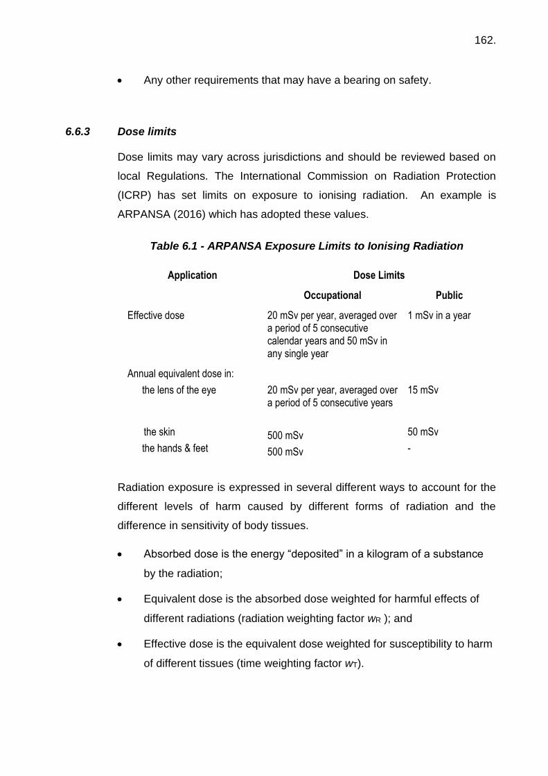
162.
• Any other requirements that may have a bearing on safety.
6.6.3 Dose limits
Dose limits may vary across jurisdictions and should be reviewed based on
local Regulations. The International Commission on Radiation Protection
(ICRP) has set limits on exposure to ionising radiation. An example is
ARPANSA (2016) which has adopted these values.
Table 6.1 - ARPANSA Exposure Limits to Ionising Radiation
Application Dose Limits
Occupational Public
Effective dose 20 mSv per year, averaged over a period of 5 consecutive calendar years and 50 mSv in any single year
1 mSv in a year
Annual equivalent dose in:
the lens of the eye
the skin
the hands & feet
20 mSv per year, averaged over a period of 5 consecutive years
500 mSv
500 mSv
15 mSv
50 mSv
-
Radiation exposure is expressed in several different ways to account for the
different levels of harm caused by different forms of radiation and the
difference in sensitivity of body tissues.
• Absorbed dose is the energy “deposited” in a kilogram of a substance
by the radiation;
• Equivalent dose is the absorbed dose weighted for harmful effects of
different radiations (radiation weighting factor wR ); and
• Effective dose is the equivalent dose weighted for susceptibility to harm
of different tissues (time weighting factor wT).

163.
6.6.4 Additional reference documents
Other documents may be used to provide practice-specific guidance on
achieving the various requirements set out in the Codes of Practice or
Regulatory requirements.
The Code requires that work practices be included in the Radiation
Management Plan. Work practices include working rules to ensure a high
standard of radiation safety and procedures that need to be followed in the
event of an incident or emergency or other likely anticipated scenarios.
The key message is to maintain distance from any source, reduce time spent
near any source and provide suitable shielding (e.g. lead).
Points to consider may include:
• Work Practices:
- Working rules,
- Emergency procedures,
- Procedures to avoid loss of a source,
- Procedures for employee training.
• Responsibilities and Duties of:
- The Responsible Person,
- General duties to ensure radiation protection in an organisation,
- The Radiation Safety Officer.
• Radiation Monitoring & Radiation Levels:
- Monitoring devices to be available,
- Survey meters.
• Storage & Transport of Gauges.
• Radiation Warning Labels and Notices.
• Licensing Issues.
An example of this type of information can be found in the ARPANSA Safety
Guide (ARPANSA 2008)

164.
Annexes to the Safety Guide provide further practical information that is
necessary to support the Code of Practice and include:
Annex A - Radiation Sources Used in Fixed Radiation Gauges covering:
• Selection of Radioactive Materials for Fixed Radiation Gauges.
• Testing of Sealed Source Encapsulation.
• X-Ray Tube and Generator Assembly Requirements.
• Neutron Generator Tubes.
Annex B – Radiation Source Containment covering:
• Requirements for RADIPACTIVE Source Containers.
• Shutters and Interlocks.
• Requirements for Shutterless Gauges.
Annex C – Radiation Monitoring and Radiation Levels:
• General Radiation Levels.
• Radiation Exposure as a Result of an Incident.
Annex D
• Radiation Warning Labels and Notices.
Annex E – Inspection Proforma:
• Information that should be included in an inspection proforma used for
inspecting a fixed radiation gauge, is provided.
Below is an example of a suitable warning label for attachment to a fixed radiation gauge containing a radioactive source

165.
Annex F – Example Wipe Test Procedure:
• Objective.
• Minimising Radiation Exposure.
• Control of Radioactive Contamination.
• Items required to Conduct a Wipe Test.
• Method for Making the Wipe Tests.
• Packaging Procedures.
Annex G – Radiation Safety Officer.
Annex H – Health Effects of Ionising Radiation and Standards for Control of
Exposure.
Annex I – ARPANSA Radiation Protection Series Publications. All these
publications are available in electronic format and can be downloaded free of
charge from ARPANSA’s website
http://www.arpansa.gov.au/Publications/Codes/rps.cfm (accessed April
2017). The ICRP also have such publications, available from
http://journals.sagepub.com/page/ani/collections/complete-issue-pdfs
(accessed 27 July 2017).

166.
7. EXPOSURE ASSESSMENT
7.1 Introduction For the hygienist to be effective in minimising the potential for adverse health
effects in the workplace, a suitable programme must be in place to anticipate,
recognise, evaluate and control any potential risks.
The following sections detail the elements of a typical programme.
7.2 Getting to know the sites
It is not unusual for a small hygiene team to be responsible for hygiene
services to multiple sites. In many cases this may involve operations spread
out over hundreds of kilometres, with workforces ranging from many to just a
few. These places aren’t always comfortable but to the hygienist they are
much more interesting than the office, and when hygienists spend time with
the workers listening to them and observing what they do, they can understand
their work and its potential health hazards. Hygienists also gain their respect
by showing interest in their work and concern for problems and hazards they
face. When they understand that hygienists are there to help them have a
better and safer workplace, they are usually more willing to spend time
discussion the issue and to wear exposure monitoring equipment when the
time comes.
Some of the work teams visited will be permanently assigned to the site, either
as company employees or as supporting contractors. They do the core routine
work of operating and maintaining the production facilities. There may also be
permanently assigned health, safety, and environmental specialists,
production laboratory technicians, emergency responders, medical
practitioners, and housekeeping, catering, security, and administrative staff
depending on the site size and location.
Other workers, not permanently assigned to the field, will arrive from outside
employers to do special work such as unusual maintenance tasks. The
167.
complex array of work groups and worksites, often changing over time, makes
for challenging and interesting work for the occupational hygiene team.
7.2.1 Initial hygiene survey & basic characterisation
The hygiene team should begin conducting basic characterisation surveys for
each of the work groups. Note that the surveys focus on the workgroups rather
than the facilities in which they work.
The task is to recognise, evaluate and control health hazards for workers who
may or may not be tied to a single facility. Any facility is likely to have several
distinct workgroups - operators, mechanics, electricians, are examples - all
with tasks and exposures specific to their trade. Site problems, like heat stress
or the presence of asbestos-containing building materials, should be identified
through the surveys of the work groups affected by them. While some
workgroups, such as operators, generally work in a single facility, others, such
as heavy overhaul mechanics or electricians, may have a central base shop
but work across multiple facilities. By organising occupational hygiene surveys
around distinct work groups, and going where the workers go, it is more likely
the full range of potential health stressors that affect each group will be
identified.
The basic characterisation survey of a workgroup begins as the hygienist
meets with several workers of the group to record a description of the group’s
duties. It is easy to miss things that may be done only occasionally or on other
shifts, or at different times of the year, so persistent questioning may be
necessary.
The next step in the basic characterisation survey is to accompany one or
more workers for a time as they go about their duties. This will make it easier
to fill in gaps in the task descriptions for the group. This is the first opportunity
to observe and identify potential health hazards for later prioritisation and
evaluation.
168.
A check of chemical storage cabinets and tool boxes for products or equipment
may also suggest activities and hazards the workers forgot to mention. A
chain saw in the tool box or two-part polyurethane paint supplies in a
flammable storage cabinet, should prompt the question “What are these used
for?”
As employees go about their tasks, record the potential chemical, physical,
and biological hazards linked to the tasks. It is essential to understand the
basics of the process, including process intermediates, and auxiliary systems
to understand what might be released during sample-taking or maintenance
work. When conducting a walk through survey, first obtain a “Safe Permit to
Work” or other necessary approval before visiting the area – the hygienist is
the same as any other visitor to the site, particularly if they are using any
monitoring equipment and remember it must be intrinsically safe or a “Hot
Work Permit” will also be required. It is often helpful to have a few direct
reading instruments along with which to collect the occasional grab sample. A
sound level meter is particularly useful in a mine site as noise hazards are
generally present. When encountering a worker grinding without hearing
protection, the opportunity presents not only to get a useful sample, but more
importantly to interact with the employee and show him or her how loud their
task actually is, and this is usually enough to get them to wear their hearing
protection. Other useful grab sampling instruments such as a multi gas meter
may be useful. Follow up sampling at a later stage can then be undertaken,
with integrated personal exposure sampling for those hazards believed to be
significant.
The most important tool, however, is probably your eyes and ears plus a
clipboard and pen and where allowed, photographs now readily obtained via
the modern day phones. Information that should be recorded includes:
• Identification of the workplace or workgroup
• Similarly exposed groups or crafts working here or based here if they
work at various field locations out of a base shop
• Work description

169.
- Key tasks they do at the site, such as in the plant or base shop
- Key tasks they do at other locations such as in the field
- Particularly hazardous locations such as confined spaces
• Health hazards—as detailed as possible
- Chemical (process, process intermediates or contaminants,
process chemical products, maintenance products, building
materials, etc.)
- Physical (noise, vibration, ionising radiation, heat or cold stress, are
typical)
- Biological (Legionella in facility water systems, dangerous
equipment around animals at remote field sites like drilling pads)
- Ergonomic hazards (turning awkward valves, repetitive motion in
maintenance tasks, heavy or awkward lifting and carrying
• Health hazard exposure assessment
- Record any results of screening samples, such as noise levels
during the survey
- Is there any fixed exposure monitoring system, such as for carbon
monoxide, hydrogen sulfide or combustible gas, and if so are data
available from these systems
- Has there been any previous exposure monitoring or assessment
and if so what results are known?
- Do they routinely do job hazard analysis, COSHH assessments, or
other risk assessments to identify health hazards and establish
controls for all their tasks?
- Which hazards should have the highest priority for OH
assessment?
• Controls in place (or needed)
- Elimination or substitution potential
- Engineering (if in place, is the maintenance programme effective?)
- Administrative or work practices and procedures permit systems
- PPE (a complete list and evaluation is important. Is it suitable,
clean, available, and employees trained and using it properly?)
• Emergency provisions

170.
- Exits
- Phones with emergency numbers
- Eyewashes and showers
- First aid kits and medical response capability
- Fire extinguishers
- Spill containment, etc
• Safety issues observed (serious safety hazards such as exposed
electrical wires, hot surfaces, unguarded machinery, fire hazards, or
working at height must not be ignored.)
• Is there a hazard communication programme in place?
- SDS system
- Chemical Inventory
- New chemical product evaluation and approval system
- Training on hazards and controls
• Are workers enrolled in medical surveillance programmes for hazards or
PPE in use? If so, what hazards?
• Any other recommendations or comments from the initial survey
From the initial survey it is possible to build a basic characterisation for the
workplace or for a similarly exposed group that works there. This is a report
that can be kept “evergreen” by updating it with the results of follow up
exposure monitoring or research. It is handy to keep the report in a word
processing file where it can be edited and published as an update with new
information periodically.
The survey report has many values, among them:
• It records conditions and information about activities, exposures and
controls in place at a given time for future reference, such as if an illness
develops or there is a claim of past exposure
• It summarises exposure assessments, often provisional, for the hazards
identified
171.
• It serves as the basis for prioritization and planning for additional
exposure monitoring to resolve uncertain exposures, or to confirm
adequacy of controls
• It informs enrolment of workers into exposure control or medical
surveillance programmes such as hazard communication training,
hearing conservation, respiratory protection, and medical exams
asbestos, benzene, lead, or chromium exposures
• It gives the occupational health staff information about the worksite, work
tasks, exposures, and PPE required for workers visiting the clinic for
fitness for work exams, routine medical surveillance, or an illness or
injury. The report should be readily available to the clinic staff, either as
a paper copy or on line
7.2.2 Exposure assessment monitoring follow-up
Generally, the initial survey and basic characterisation will suggest the need
for some exposure monitoring either because the exposure was uncertain, or
because there is a need to quantify exposures in support of medical
surveillance. For example:
• The survey may have identified high noise areas in a plant but there is
some uncertainty whether workers spend enough time in them to develop
exposures over the OEL. By conducting personal noise dosimetry on a
representative set of workers going about their normal duties, it is
possible to characterise those exposures better, and thus inform the
audiometric monitoring programme. Exposure data will also be available
to inform a future hearing loss case evaluation if needed.
• Mechanics make repairs on process equipment and may be subject to
high but variable dust exposures. Only monitoring will allow their
exposure profile to be characterised with any confidence.
• Special maintenance tasks, such as welding or asbestos removal, need
to be assessed to determine whether control systems are adequate for
the exposures. There may also be regulatory requirements for some
such assessments.

172.
Planning for some of these monitoring events is possible in advance, but there
is a need to be ready to use sampling equipment on short notice when advised
of a special opportunity.
Assessment methods will be informed by the process discussed earlier and by
the methods covered in other training modules such as on chemicals or noise.
7.3 Exposure assessment
The central task of the mine site hygiene programme is to assess workplace
health hazard exposures and make judgements about the adequacy of
controls. The health hazards may be chemical, physical, biological or
ergonomic. The exposure assessment process is applied for new
construction, routine operations and maintenance, major maintenance,
renovations, emergency response and demolition activities. The results of
exposure assessments inform decisions about:
• the most appropriate type and level of control,
• training needs for workers,
• enrolment of workers in medical surveillance programmes,
• treatment of occupational health cases,
• compliance assurance, and
• design of future facilities, work processes, or response activities.
Exposure assessment data can also be used in epidemiological studies.
Epidemiology is concerned with the statistical study of disease patterns in
groups of individuals. It traditionally had a role in the study of epidemics of
infectious diseases, but it has evolved and also looks at non-communicable
diseases such as those seen in occupational environments. It studies the
distribution of death and illness in populations. Hence, occupational hygiene’s
process of collection of data is relevant to the detection of hazards to health
now and particularly in the future. Biostatistics are often employed in
epidemiology to assess the data from designed (prospective / cohort) studies
or from historical data collection (retrospective / case-control studies).

173.
The AIHA Exposure Assessment Strategy, developed by the AIHA Exposure
Assessment Committee (AIHA 2015) provides a model for assessment of all
these seemingly disparate kinds of activities, as does the AIOH (2014)
Occupational Hygiene Monitoring and Compliance Strategies guidebook.
Another useful reference is EN 689 Workplace Exposure. Measurement of
exposure by inhalation to chemical agents. Strategy for testing compliance
with occupational exposure limit values.
It is helpful to commence with a brief summary of the strategy as it informs as
to the overall approach. The basic strategy is shown schematically in
Figure 7.1.

174.
(Source: AIHA)
Figure 7.1 – AIHA Exposure Assessment Strategy Flow Diagram
Start
Basic Characterisation
Exposure Assessment
Uncertain Unacceptable Exposure
Acceptable Exposure
Improve Control
Reassessment
Further Information Gathering

175.
The starting point in an exposure assessment exercise may be the need to
assess an anticipated new process, new facility, new work task, demolition,
task, or conceivable emergency situation that is not yet present. Or, it may be
a walkthrough survey of an existing workplace, process, or workshop, a
developing emergency (e.g. a hazmat spill), or a demolition in progress.
The next step is to develop a basic characterisation about the work being done,
who is doing it, the chemical, physical, biological or ergonomic hazards
associated with it, and the controls in place. Sources of information may
include process diagrams, task step descriptions, safety data sheets,
walkthrough observations, discussions with site workers, supervisors, or
engineers, mathematical exposure monitoring, available monitoring results,
industry specific technical publications and any other relevant information.
If workplace exposure monitoring is required (in most cases it is necessary to
improve the decision process), then an evaluation of the data must be
conducted as part of the exposure assessment process. In the majority of
cases (especially where a significant amount of data is available), statistical
tools are used to develop an exposure profile for the situation of concern.
As a result of this process, decisions can then be made as to the adequacy of
the controls in place and if necessary, what remedial action is necessary.
This process continues until all exposures are considered acceptable and a
reassessment process (commonly called a maintenance programme) is in
place and functioning.
7.3.1 Identification of similar exposure groups (SEGs) While the goal is to protect each individual worker, limited resources usually
mean that occupational hygienists need to:
• aggregate workers into exposure groups,
• determine which exposure groups require priority attention (through risk
assessment), and
• evaluate the measured ‘exposure profile’ of each SEG in order of priority.

176.
Identification of SEGs is the process where the employees of a workforce are
divided into groups of similar potential exposure, based on past monitoring
data or via using the knowledge of persons working in the plant as to possible
exposures.
A number of persons in each group are then monitored and it is assumed that
the exposures measured represent that of the whole group (SEG).
The allocation of workers to SEGs can be accomplished in a number of ways,
including:
• Observational - simplest form but least accurate;
• Sampling - preliminary sampling to establish groups; or
• Combination of observation and sampling - most accurate approach.
In establishing SEGs, they can be defined by:
• Process and environmental agent;
• Process, job and environmental agent;
• Process, job, task and environmental agent;
• Work teams; or
• Non-repetitive work.
While this may seem a simple task, it is actually quite complex and time spent
in the initial stages getting it as close as possible for a particular site, will pay
benefits at a later stage.
SEGs should be revised when:
• New data is available;
• A change to the process occurs;
• New jobs are created; or
• New contaminants may be present.

177.
As data increases so does the level of confidence (or lack of confidence) in the
SEGs, which then allows judgement on exposure to be made on a sound
basis.
7.3.2 Exposure profile / statistical analysis
The next step of assessment is to estimate the exposure profile for each SEG
for potentially significant exposures. The assessment needs to be structured
so as to focus time and effort on the most significant exposures - that is those
with the potential to reach or exceed OELs or otherwise to threaten worker
health.
Many people think of occupational hygienists as people who perform air or
noise monitoring, but hygienists frequently assess exposures without
conducting any sampling at all.
It is possible to quickly dismiss obviously low exposure situations such as the
use of a substance with low toxicity, low vapour pressure, in small amounts or
for brief times, with no apparent regulatory issues, considered of minor risk
and adequately controlled. Similarly, it is known that use of a slow turning drill
press to drill holes in a steel plate will not contribute significantly to a noise
dose. There is little to be gained by doing exposure monitoring in these
situations and the hygienist should move on to more important concerns,
provided they are sure of their findings and have the relevant training and
experience to make such judgements.
Unfortunately, cases are also encountered in which exposures are obviously
unnecessarily high or fall short of regulatory or industry norms. A worker
welding in an enclosed area without exhaust ventilation is clearly exposed to
more fume than necessary and may well have metal fume exposures
exceeding OELs. Many countries have specific regulations calling for
ventilation control of welding fumes, so there may be an obvious compliance
problem, as well. Similarly, the assistant using a disk grinder to prepare metal
for welding or to grind welds is certainly exposed to noise exceeding 100 dB(A)

178.
and unquestionably needs very effective hearing protection and should be
enrolled in a hearing conservation programme.
Immediate action is needed to control these exposures and strong
recommendations should not be delayed for the results of exposure
monitoring. Instead, hygienists should draw on experience in past monitoring
and knowledge of occupational hygiene standards, normal practice and
regulatory requirements in concluding without sampling that the level of control
is inadequate. It may be necessary to conduct monitoring later after the
recommended control is installed to test its effectiveness, but the priority is
always controlling worker exposures not measuring them.
The broad uncertain middle ground is home to the most interesting exposure
assessments. Here exposures are neither clearly adequately controlled, nor
clearly inadequately controlled. Usually these are situations, or combinations
thereof, where observation alone leaves uncertainty as to the level of exposure
with regard to an OEL. There is a need to measure the chemical or physical
agent under the various work conditions that may prevail, using the specialised
equipment and methods of occupational hygiene. In some situations,
hygienists are required to take measurements for regulatory assurance
purposes. The ultimate goal is to characterise quantitatively the exposure
profile for comparison with the OEL and to do so with some statistical
assurance.
Once groups of similarly exposed workers are identified, it is possible to
develop a sampling strategy to characterise the exposures. Experience has
shown that the workers in a SEG don’t all have the same exposure level every
day. There is a lot of variability even for a single worker from day to day and
even more variability across the group over the year. So, when and how does
the hygienist sample to make a useful estimation of the exposure profile?
If the interest is only whether there are exposures over a compliance limit, one
approach is to try to find and sample “worst case” situations. If these worst-
case situations are well below the exposure limit, then the other more common

179.
situations should be even lower and it may be reasonably concluded that there
isn’t a compliance problem.
On the other hand, if the worst-case sampling does indicate an overexposure,
more work is necessary to control exposures in at least those cases.
There are some pitfalls to worst case monitoring. To begin with, it suggests
that a relatively low number of samples will be taken. The fewer the number
of samples the less confident the hygienist can be in the characterisation and
conclusions. More samples generally mean more confidence, at least up to a
point. If the worst-case sampling finds exposures near or over the OEL, and
no further evaluation is performed, the result may drive broad application of
controls, such as respirator use, at times when they are not needed or
desirable. It is also possible that what was thought to be the worst case was
not, and that the assurance of being within the limits was false. Thus, worst
case sampling may be useful as a first cut but it falls short of producing a
reliable estimate of the true exposure profile and may lead to erroneous
conclusions.
Random sampling, with a statistically sufficient number of samples, is
theoretically the most reliable means of establishing an exposure profile for
workplace health hazard exposures but it is also costly in both time and
resources. Broad experience with occupational hygiene exposure monitoring
suggests that the true population of exposures for a SEG is best modelled as
a lognormal distribution, described by a population geometric mean or an
estimate of the arithmetic mean (i.e. minimum variance unbiased estimate -
MVUE) and geometric standard deviation (Figure 7.2). Most of the exposures
will be clustered to the lower end of the distribution, but a few may be much
higher, even several times higher than the mean. Clearly, only one or two
samples cannot be expected to represent the entire range of exposures for the
SEG. It is the upper end of the distribution (those higher exposure days) that
is of most concern because that is where the over exposures will most likely
be. Any single sample will most likely be from the lower end of the exposure
distribution, where most of the exposures are clustered.

180.
That is why taking only one or a very few samples is likely to understate the
exposure range and may lead to a conclusion that the hazard is sufficiently
controlled when it is not. If enough samples are collected, eventually some
representation of the higher exposures will be evident, particularly if they are
randomly drawn or at least close to that ideal.
(Source: AIHA IHStat; Ian Firth)
Figure 7.2 – Idealised Lognormal Distribution of Occupational Hygiene Sampling Data

181.
Statistical tools, such as IHSTAT from the AIHA and BWStat from
BOHS/NVvA, can be used to estimate what proportion of the exposures may
exceed the OEL. To use such tools, the samples must be all the same type;
e.g. all short-term samples, or all full shift TWA samples.
The statistical tools use the sampling data to generate a theoretical lognormal
distribution with geometric mean or MVUE, and geometric standard deviation,
that is intended to represent as reasonably as possible, the actual distribution
of exposures for the SEG. A key indicator is the population’s 95% upper
confidence limit (UCL), for it is common to conclude that an exposure profile is
adequately controlled if the hygienist can be 95% confident that the true
population mean exposure falls below the OEL. Thus, if the 95% UCL is below
the OEL, that criterion is met. However, because not all possible worker-days
were - or can be sampled - there is uncertainty in location of the 95% UCL.
Fortunately, statistical tools can calculate that uncertainty.
The lognormal curve in the example in Figure 7.2 is the theoretical lognormal
distribution of exposures for a SEG. It was generated from what might have
been 16 random samples for an air contaminant with an OEL of 5. Note that
the point estimate of the 95% UCL of the SEGs modelled exposure distribution
is above the OEL of 5. It appears that more than 5% of the time exposures
will exceed the OEL. If that is used as the criterion for sufficient control, this
analysis suggests that controls are inadequate. Had the 95% UCL been well
under 5 it would have been concluded by the same criterion that exposures
were sufficiently controlled. Theoretically a random sampling data set of 6-10
samples is enough to generate a reasonable estimate of the profile and as
more samples are added this will narrow the tolerance intervals on the key
statistical metrics. The random sampling model assumes that the same work
goes on in much the same way all the time, and that it is possible to collect
samples on any day, any shift, and any person and achieve the same result.
In practice that idea seldom is achievable.
182.
As it turns out, truly random sampling is not always feasible, or sufficiently
timely, particularly if the hygienist doesn’t have up to a full year to sample
before making a decision. In practice, they are more likely to sample during
one or more relatively short campaigns during which they try to capture
situations believed to represent the actual distribution of exposures. Caution
is due however, as sampling what are thought to be representative conditions
may introduce bias. The results may reflect the conditions thought to be
representative but not necessarily the full exposure profile. For example,
conditions or activities with differing exposures may happen at other times of
the year, or even on other shifts (e.g. production rates might be higher in winter
than in summer). Major maintenance activities may create greater or lesser
exposure potentials than during normal operations. Furthermore, samples
clustered in a limited time period may be auto-correlated leading to inaccurate
estimates of the mean and underestimates of the variability. There may be a
need to do extra samples or try to add more samples to the data set at other
times of the year to improve the confidence. The more deviation from a
random sampling strategy the more conservative an approach may need to be
taken in our interpretation of the results. Communicating effectively the limits
of sampling results in reports is challenging but essential to be sure that
managers do not take a simplistic view and take inappropriate action.
In practice, most hygienists apply some combination of the above sampling
strategies in assessing exposures. Most would sample a few worst-case
situations as a first cut to gauge roughly the potential for overexposure or
compliance failures. Then it is common to continue with one or more campaign
sampling events, trying to get a few samples from each shift, perhaps over a
week or two. When time allows in succeeding months, it may be possible to
return to gather additional samples to build the database and improve the
characterisation.
When there are unusual maintenance tasks, such as a vessel clean out, a
fabrication project, an asbestos abatement, or a major painting job, being
conducted on site, exposure monitoring should be planned to see if the
controls that were specified for the work are indeed effectively controlling
exposures. These projects are generally short-term, so campaign sampling is

183.
the norm, and sampling may be more or less continuous during the work in
order to get enough samples for an exposure profile. Documentation of the
controls in place and relevant exposures from a job today can be highly
valuable when a similar job is planned next year.
In many organisations there are significant quantities of data collected and it
is important that this data is stored securely and confidentially. Monitoring
records and collected data must be stored in a secure location for assessment
and future access. This may vary between jurisdictions but in some cases can
be as long as 30 years. Due to stringent confidentiality laws in most
jurisdictions the security access must be controlled and limited.
Where ever possible, storing data on personal computers/hard drives must be
avoided and they should be stored on secure network systems in which the
data is backed up regularly. Currently there are a number of commercial
programmes available that can be used.
7.3.3 Acceptability of the exposure profile
Regardless of whether qualitative or quantitative means (or perhaps more
likely some combination of both) have been used to collect data, some
judgement regarding the acceptability of the exposure must be made.
The result of any assessment, whether initial with little data, or one developed
over time with a lot of data and statistical analysis, will be the judgment as to
whether the exposure profile is acceptable, uncertain, or unacceptable with the
controls being used. Occupational hygiene practice today suggests that
exposures to agents of chronic concern may be considered adequately
controlled when the vast majority of exposures are a small fraction of the
exposure limit, and exposures over the limit relatively rare. That said, any
identified exposure over an OEL should be investigated and some
organisations have self-imposed “action levels” set at a percentage of the OEL
(usually 50%). Considerations could be:
• Does the overexposure indicate that something was missed in the
original assessment and control design?
184.
• Is the control system occasionally unreliable?
• Is there a gap in training for the workers?
• Is it necessary to improve the work procedures?
A judgement of acceptable exposure should be documented in writing by a
report for future reference. There should be a schedule for future
reassessment, with more exposure monitoring if necessary, to see if the
controls continue to be adequate. All workplaces have turnover in staff - both
in management and employees.
Control systems may wear out or fail to keep up with changes in the process
or production rates. There may also be regulatory requirements for
reassessment periodically.
A judgement of uncertain exposure requires further assessment. More
information about the hazard and how it affects workers may be helpful. For
example, it may be decided to do exposure monitoring where none had been
done, sample by another method, or take more samples to increase the
confidence in the conclusions. If initial grab sampling with a direct reading
instrument was inconclusive, follow up with integrated personal sampling of
multiple workers over several days may be necessary to be more certain about
whether exposures may be exceeding an OEL. If only full shift sampling was
performed, it may still be necessary to sample for short-term exposures during
any expected high exposure times. Uncertainty may remain even after
significant samples have been taken if conditions differ at another time of year.
The hygienist will plan another round in the future to broaden the
characterisation.
A judgement of unacceptable exposure calls for a prompt recommendation
for immediate action to reduce the exposures. Most operations are not shy
about stopping work if necessary until the deficiency can be corrected, but it
may be possible to apply or upgrade PPE, or modify work practices for the
short term, thereby allowing the task to continue while more reliable
engineering controls or process changes can be introduced. After improved

185.
controls are in place the assessment process is repeated to check the
effectiveness of the control.
7.3.4 Biological exposure monitoring
Biological exposure monitoring usually supplements workplace exposure
monitoring (except for lead exposure) and involves the determination of a
parent chemical, or a mixture of chemicals (e.g. pyrene for PAHs), by
assessing the level of a metabolite of that chemical in body fluids (blood or
urine) or expired air. It can be used to determine the total body burden of a
substance and is also useful in determining the effectiveness of controls such
as PPE.
It is particularly useful in situations where the substance of interest can bio-
accumulate such as in the cases of some heavy metals. Substances in mining
and allied processes in which biological monitoring may be utilised include but
are not limited to:
• Arsenic
• Cadmium
• Fluoride
• Lead
• Mercury
• Polycyclic Aromatic Hydrocarbons (PAHs)
• Uranium
It is important to note that the ACGIH in their TLV®/BEI® booklet they specify:
“BEIs® are intended as guidelines to be used in the evaluation of potential
health hazards in the practice of occupational hygiene. BEIs® do not indicate
a sharp distinction between hazardous and non-hazardous exposures.”
(ACGIH 2016)

186.
7.4 Continuous improvement cycle The exposure assessment process depicted in Figure 7.1 is really a
continuous improvement process. The concept is to reach a point where it is
possible to cycle around it until it is possible to document assurance of
adequate control. At that point, it is possible to move on to the next exposure
assessment priority but with the intent to revisit the loop periodically to be sure
the controls remain effective.
The hygiene programme needs to focus on the long-term exposure
assessment strategy for workplaces and for special projects, assuring that the
exposure control processes and programmes are being implemented
effectively, while also responding to short term issues that arise, including
emergency situations. In the background, hygienists have to spend time
maintaining equipment, reference library and supplies, assuring that contracts
are in place for laboratory and other services, and building professional skills
and achieving and maintaining certification.
These background items maintain personal capability to do the core work of
exposure assessment and control verification.
7.5 Reporting results
Occupational hygiene surveys and exposure monitoring assessments are of
limited value unless they are documented in clearly written and timely reports.
Many hygienists, trained in the sciences, tend to write reports in a formal style
with passive, third person voice. While the author may intend for the report to
communicate an air of objectivity and scientific veracity, this writing style
conflicts with the important purpose of communicating the results in an
understandable manner. Too often, the information the business manager
really needs is buried at the far end of the report.
A more effective approach is to write the report like a newspaper article, with
the most important ideas and conclusions right up front. This is most often
achieved in an executive summary on the first page. News articles lead with
187.
the news, using active voice to tell the reader what it means for them in the
future. For example:
Painting crews must continue to use full-face air purifying respirators
while re-coating the inside surfaces of produced water tanks because
paint solvent vapour exposures exceed occupational exposure limits,
according to occupational hygiene monitoring on 11 June. Forced
ventilation of the large tanks is helpful, and should continue to be applied,
but the internal structures create dead spots where vapours remain
elevated.
Or:
Plant operators must wear double hearing protection in the crusher
where noise levels were found to reach 110 dB(A) during our 18 August
occupational hygiene noise survey. Although operators spend only a
small portion of their shift in this area, personal noise dosimetry the same
day showed exposures can exceed the daily exposure limit by nine times.
All operators must be enrolled in the company hearing conservation
programme, have annual audiograms and training, and be fitted for
hearing protection.
This should be followed with supporting information, including information such
as how the monitoring was conducted, where samples were analysed, and a
table of sample results as compared to the OEL - but the manager, crew
supervisor, or worker already knows what action to take after reading the first
two or three sentences.
It is not our purpose to detail how to write reports, and indeed your business
may have their own preferred layouts and styles. What doesn’t vary though is
the responsibility to get the information across clearly and effectively. If the
reader doesn’t understand the meaning or is unwilling to read through our
report to find the key conclusion, the failure to communicate is the
responsibility of the hygienist alone.
188.
7.6 Application of control strategies
The principles of control of health hazard exposures in the work place covered
in the module on controls apply perfectly well to the mining industry. The
hierarchy of controls guides us toward implementing the most reliable control
possible for the work situation consistent with our assessment of the exposure
and risk. Regulatory rules may dictate specific controls for particular hazards,
such as asbestos or lead exposures, or for specific tasks such as welding or
spray painting. Control recommendations must at a minimum meet regulatory
requirements but should also seek ways to improve on that minimum in a
fit-for-purpose manner reflecting the exposure assessment and level of risk.
The value of occupational hygiene assessments is most appreciated by both
workers and managers when they fine tune the control system such that it is
sufficient to assure that exposures are sufficiently controlled but the workers
are not burdened by excessive controls.
If it is possible to recommend a temporary local exhaust system for a process
maintenance task so that respiratory protection is not needed, the workers may
be more comfortable and productive. Similarly, when exposure monitoring
shows that painters can safely downgrade from air-supplied to air-purifying
respirators, everyone is usually happier.
7.7 Development of effective control programmes
The application of occupational hygiene controls is most effective when they
are carefully thought out in advance and consistently applied. There is a need
to have uniform standards for when and how to use various kinds of controls,
for testing effectiveness, and for supporting medical surveillance or approval
relating to the exposure or control system. This can assure consistency and
quality in control applications through written control programmes. These
programmes may address worker protection for specific hazards such as
asbestos or blood-borne pathogens, or they may set forth procedures for use
of a specific kind of control, such as respirator or hearing protection use.
Documented programmes help drive consistency in approach, methods, and
decision making. They are an anchor, without which there is a tendency to

189.
drift. It is also valuable to have a reference to return to when an issue hasn’t
been worked on for a year or so, or when a new hygienist takes on the site
role. When the programme is posted on a web site, it serves to help others
understand how the issue is being managed and the responsibilities of the
various persons.
Control programmes provide guidance to the organisation about a number of
important topics including:
• Activities that may generate potential exposures above applicable
exposure limits?
• Recommended work practices and/or control of work permits needed to
be issued?
• Roles and accountabilities that are required for members of the work
force and supervision?
• Regulatory compliance expectations and/or notifications required by
law?
• Training requirements necessary to educate the work force on the
hazards?
• Medical health surveillance programmes that may be necessary to
monitor the health of the work force?
Any site programme must be site-specific, fully addressing the local regulatory
requirements, the specific operations and exposures of the site and the
relevant functional controls. Therefore, site programmes may vary in detail but
the fundamental principles remain the same.
In the Exposure Assessment Programme, the hygiene team organises and
documents it’s procedures and plans for this key activity. This programme
mainly serves the hygiene team. Sections of the programme may include:
• Statement of purpose.
• Types of sampling the team is prepared to do or can do.

190.
• Equipment list and location.
• Equipment service schedule.
• Procedures for calibration and use of various sampling equipment, such
as:
- Noise dosimeters
- Air sampling pumps
- Calibration equipment
- Diffusion monitors
- Radiation meters
- Direct reading colorimetric instruments
- Multi gas monitors
- Photoionisation detectors.
• Provisions for laboratory analysis:
- Preparing samples for shipment
- Shipping procedures
- Tracking of samples sent for analysis
- Receiving and logging of results.
• Laboratory services (internal or external) criteria for analysis:
- Adequate / validated analysis methodologies (i.e. NIOSH, OSHA,
HSE);
- Quality control / quality assurance (QC/QA) procedures;
- Staff who are skilled and experienced in the analysis of occupational
/ industrial hygiene samples; and
- Accreditation for the actual analyses that are required.
• Data entry into electronic databases if used.
• Data analysis, use of statistical programmes.
• Report writing - including templates.
• Schedule of planned monitoring for the year.
One of the major problems at remote mine sites is poor change management
and this applies to the hygiene profession. A detailed programme, as indicated
above, at least gives the person following the incumbent a chance of knowing
the site status.

191.
8. REFERENCES
ACGIH (2016): 2016 TLVs and BEIs; Threshold Limit Values for Chemical
Substances and Physical Agents and Biological Exposure Indices. American
Conference of Governmental Industrial Hygienists ACGIH – available from
http://www.acgih.org/forms/store/CommercePlusFormPublic/search?action=F
eature.
AIHA (2015): A Strategy for Assessing and Managing Occupational Exposures
4th edn, American Industrial Hygiene Association (AIHA) 2015 – available from
https://www.aiha.org/marketplace/Pages/default.aspx.
AIOH (2004): A Guideline for the Evaluation and Control of Diesel Particulate
in the Occupational Environment, AIOH, 2004 – available from
https://www.aioh.org.au/onlinestore/publications.
AIOH (2006): Simplified Occupational Hygiene Risk Management Strategies,
AIOH June 2006 - available from
https://www.aioh.org.au/onlinestore/publications.
AIOH (2013): A Guide to Managing Heat Stress: Developed for use in the
Australian Environment, AIOH November 2013 – available from
https://www.aioh.org.au/onlinestore/publications.
AIOH (2014): Occupational Hygiene Monitoring and Compliance Strategies,
AIOH, 2014 – available from https://www.aioh.org.au/onlinestore/publications.
ANSI/ISEA Z87.1 (2015): American National Standard for Occupational and
Educational Personal Eye and Face Protection Devices – available from
http://webstore.ansi.org/RecordDetail.aspx?sku=ANSI%2fISEA+Z87.1-2015.
ARPANSA (2005): Code of Practice and Safety Guide for Radiation Protection
and Radioactive Waste Management in Mining and Mineral Processing,
Australian Radiation Protection and Nuclear Safety Agency (ARPANSA),
Radiation Protection Series No. 9 – available from
http://www.arpansa.gov.au/Publications/Codes/rps9.cfm.
ARPANSA (2007): Code of Practice and Safety Guide for Safe Use of Fixed
Radiation Gauges, Australian Radiation Protection and Nuclear Safety Agency

192.
(ARPANSA), Radiation Protection Series No. 13 – available from
http://www.arpansa.gov.au/Publications/Codes/rps13.cfm.
ARPANSA (2008): Safety Guide for the Management of Naturally Occurring
Radioactive Material (NORM), Australian Radiation Protection and Nuclear
Safety Agency (ARPANSA), Radiation Protection Series No. 15 – available
from http://www.arpansa.gov.au/Publications/Codes/rps15.cfm.
ARPANSA (2014): Fundamentals for Protection Against Ionising Radiation,
Australian Radiation Protection and Nuclear Safety Agency (ARPANSA)
Radiation Protection Series (RPS) F-1 – available from
http://www.arpansa.gov.au/Publications/Codes/rpsF-1.cfm.
ARPANSA (2016): Code for Radiation Protection in Planned Exposure
Situations, Australian Radiation Protection and Nuclear Safety Agency
(ARPANSA) Radiation Protection Series (RPS) C-1 – available from
http://www.arpansa.gov.au/Publications/Codes/rpsc-1.cfm.
AS/NZS 1269 Set: 2005 Occupational Noise Management Set – available from
https://infostore.saiglobal.com/en-
au/Search/Standard/?sortKey=productName-
asc&productFamily=STANDARD.
AS 1319: Safety Signs for the Occupational Environment, 1994.
AS/NZS 1336: Recommended Practices for Occupational Eye Protection,
1997.
AS/NZS 1337: Personal Eye protection 1992 – 2014.
AS/NZS 1715: 2009 Selection Use and Maintenance of Respiratory Protective
Devices.
AS/NZS 1716: Respiratory Protective Devices, 2012.
AS/NZS 2161: Occupational Protective Gloves (set), 2008.
AS 2670.1-2001: Evaluation of human exposure to whole-body vibration –
General requirements, Standards Australia – available from
https://infostore.saiglobal.com/store/details.aspx?ProductID=278805.

193.
AS/NZS 2865: Confined Spaces, 2009.
Australian Government (2016): Hazardous Materials Management - Leading
Practice Sustainable Development Program for the Mining Industry – available
from https://www.industry.gov.au/sites/default/files/2019-04/lpsdp-hazardous-
materials-management-handbook-english.pdf.
Cecala, A.B., O'Brien, A.D., Schall, J., Colinet, J.F., Fox, W.R., Franta, R.J.,
Joy, GJ., Reed, W.R., Reeser, P.W., Rounds, J.R. & Schultz, M.J. (2012):
Dust Control Handbook for Industrial Minerals Mining and Processing. IMA-
NA / NIOSH, RI9689 – available from
https://www.cdc.gov/niosh/mining/works/coversheet1765.html.
Coal Services Health & Safety Trust (2008): Keeping Coal Miners Health at
Work – An Occupational Hygiene Manual for the Coal Mining Industry –
available from
http://www.hstrust.com.au/MessageForceWebsite/Sites/326/Files/20545_Ke
eping_Coal_Miners_Healthy_At_Work_Rev3.pdf.
Haynes, A. (2008): Review and Assessment of Health Risks During Solvent
Application in Rubber Belt Splicing and Repairs, Proceedings of the
26th Annual Conference of the AIOH, 2008.
HB 213: Guidelines for Safe Working in a Confined Space, 2003 – available
from https://infostore.saiglobal.com/store/details.aspx?ProductID=568827.
Henderson, J., Monitoring Programmes and Selection of Respiratory
Protection, Australian Tunnel Construction Safety Seminar, Australian
Underground Construction and Tunnelling Association (AUCTA), Sydney 2001
ICMM (2009): Good Practice Guidance on Occupational Health Risk
Assessment, International Council on Mining & Metals (ICMM) – available from
https://www.icmm.com/gpg-occupational-health.
ISO 2631-1 (1997): Mechanical vibration and shock - Evaluation of human
exposure to whole-body vibration - Part 1: General requirements. International
Organisation for Standardisation (ISO) – available from
https://www.iso.org/standard/7612.html.

194.
Joint Coal Board, Occupational Health and Rehabilitation, Technical Bulletin,
May 1991 “The Occupational Diseases and Injuries Prevalent in the NSW Coal
Mining Industry”.
Kee, S. (1996) An Occupational Hygiene Evaluation of Exploration Drilling
Activities. Proceedings of the Australian Institute of Occupational Hygienists,
1996.
McPhee, B., Foster, G., & Long, A., (2009): Bad Vibrations – A Handbook on
Whole Body Vibration in Mining, Coal Services Health & Safety Trust –
available from http://www.hstrust.com.au/ManualHandlingandVibration.aspx.
MSHA (2000): Noise Source Identification Project, Draglines, Shovels and Air
Arc Gouging.
Safe Work Australia (2015): Model Code of Practice - Managing Noise and
Preventing Hearing Loss at Work – available from
http://www.safeworkaustralia.gov.au/sites/swa/about/publications/pages/man
aging-noise-preventing-hearing-loss-cop.
Safe Work Australia (2016): Model Code of Practice - Confined Spaces –
available from
http://www.safeworkaustralia.gov.au/sites/swa/about/publications/pages/confi
ned-spaces-cop.
Safe Work Australia (2016): Model Code of Practice - How to Manage and
Control Asbestos in the Workplace – available from
http://www.safeworkaustralia.gov.au/sites/swa/about/publications/pages/man
age-control-asbestos-cop.
Safe Work Australia (2016): Model Code of Practice – Welding Processes –
available from
http://www.safeworkaustralia.gov.au/sites/swa/about/publications/pages/weld
ing-processes.