Embed Size (px)
Citation preview
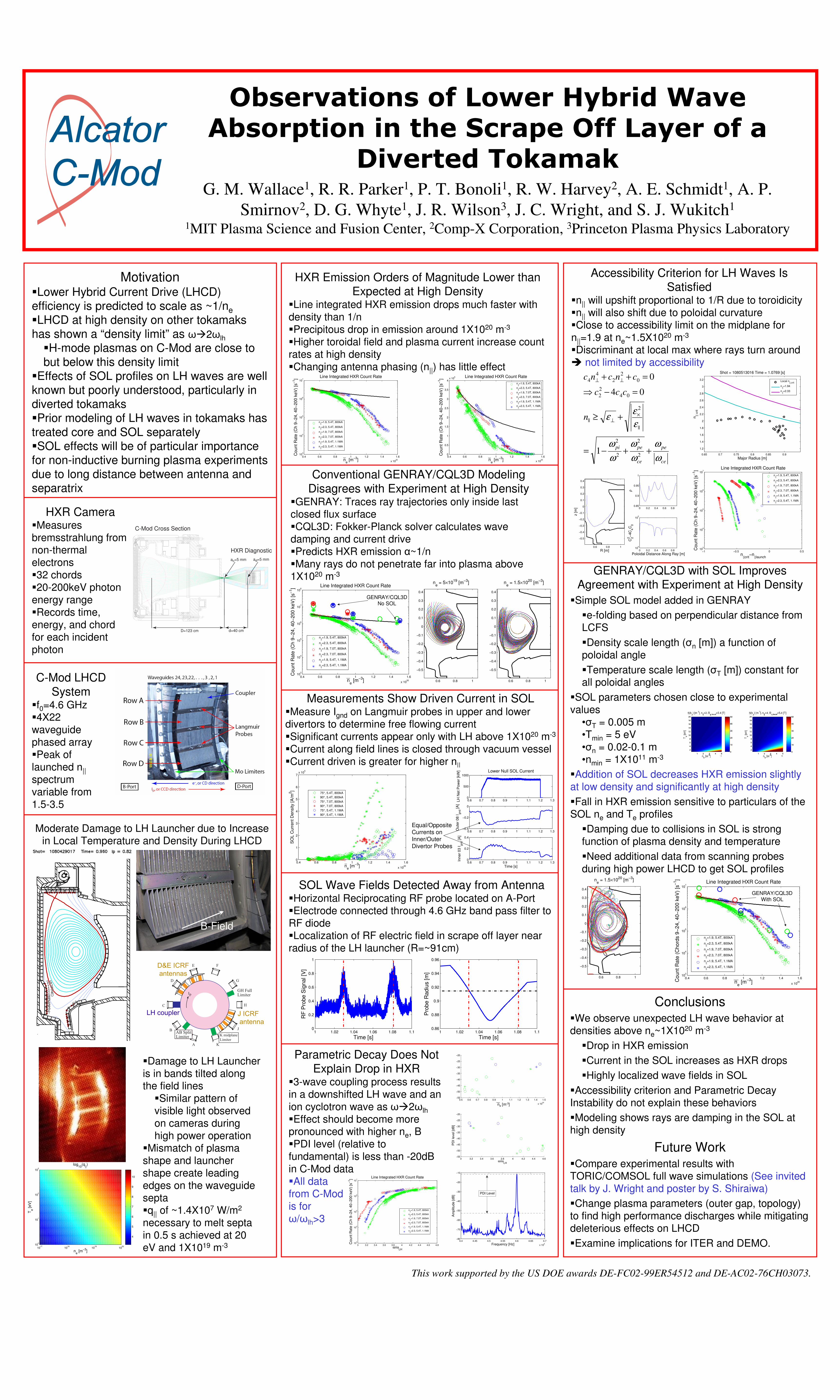
Observations of Lower Hybrid Wave Absorption in the Scrape Off Layer of a
Diverted TokamakG. M. Wallace1, R. R. Parker1, P. T. Bonoli1, R. W. Harvey2, A. E. Schmidt1, A. P.
Smirnov2, D. G. Whyte1, J. R. Wilson3, J. C. Wright, and S. J. Wukitch1
1MIT Plasma Science and Fusion Center, 2Comp-X Corporation, 3Princeton Plasma Physics Laboratory
This work supported by the US DOE awards DE-FC02-99ER54512 and DE-AC02-76CH03073.
A
B
C
D
E
K
J
G
F
H
GH FullLimiter
J ICRF
antenna
AB SplitLimiter
Ip
K midplane
Limiter
D&E ICRF
antennas
LH coupler
C-Mod LHCD
System�f0=4.6 GHz�4X22
waveguide
phased array
�Peak of
launched n||
spectrum
variable from
1.5-3.5
HXR Camera�Measures
bremsstrahlung from non-thermal
electrons
�32 chords
�20-200keV photon
energy range
�Records time,
energy, and chord
for each incident
photon
HXR Emission Orders of Magnitude Lower than
Expected at High Density�Line integrated HXR emission drops much faster with
density than 1/n
�Precipitous drop in emission around 1X10²⁰ m-3
�Higher toroidal field and plasma current increase count
rates at high density
�Changing antenna phasing (n||) has little effect
Parametric Decay Does Not
Explain Drop in HXR�3-wave coupling process results
in a downshifted LH wave and an
ion cyclotron wave as ω�2ωlh
�Effect should become more pronounced with higher ne, B
�PDI level (relative to
fundamental) is less than -20dB
in C-Mod data
�All data
from C-Mod
is for
ω/ωlh>3
Conclusions�We observe unexpected LH wave behavior at
densities above ne~1X10²⁰ m-3
�Drop in HXR emission
�Current in the SOL increases as HXR drops
�Highly localized wave fields in SOL
�Accessibility criterion and Parametric Decay
Instability do not explain these behaviors
�Modeling shows rays are damping in the SOL at
high density
Future Work�Compare experimental results with
TORIC/COMSOL full wave simulations (See invited
talk by J. Wright and poster by S. Shiraiwa)
�Change plasma parameters (outer gap, topology)
to find high performance discharges while mitigating
deleterious effects on LHCD
�Examine implications for ITER and DEMO.
GENRAY/CQL3D with SOL Improves
Agreement with Experiment at High Density
�Simple SOL model added in GENRAY
�e-folding based on perpendicular distance from
LCFS
�Density scale length (σn [m]) a function of
poloidal angle
�Temperature scale length (σT [m]) constant for all poloidal angles
�SOL parameters chosen close to experimental
values
•σT = 0.005 m
•Tmin = 5 eV
•σn = 0.02-0.1 m
•nmin = 1X10¹¹ m-3
�Addition of SOL decreases HXR emission slightly
at low density and significantly at high density
�Fall in HXR emission sensitive to particulars of the
SOL ne and Te profiles
�Damping due to collisions in SOL is strong
function of plasma density and temperature
�Need additional data from scanning probes
during high power LHCD to get SOL profiles
Conventional GENRAY/CQL3D Modeling
Disagrees with Experiment at High Density�GENRAY: Traces ray trajectories only inside last closed flux surface
�CQL3D: Fokker-Planck solver calculates wave
damping and current drive
�Predicts HXR emission α~1/n
�Many rays do not penetrate far into plasma above
1X10²⁰ m-3
Measurements Show Driven Current in SOL�Measure Ignd on Langmuir probes in upper and lower
divertors to determine free flowing current
�Significant currents appear only with LH above 1X10²⁰ m-3
�Current along field lines is closed through vacuum vessel
�Current driven is greater for higher n||
SOL Wave Fields Detected Away from Antenna�Horizontal Reciprocating RF probe located on A-Port
�Electrode connected through 4.6 GHz band pass filter to
RF diode
�Localization of RF electric field in scrape off layer near
radius of the LH launcher (R=~91cm)
�Damage to LH Launcher
is in bands tilted along the field lines
�Similar pattern of
visible light observed
on cameras during
high power operation
�Mismatch of plasma
shape and launcher
shape create leading
edges on the waveguide
septa�q|| of ~1.4X10⁷ W/m2
necessary to melt septa
in 0.5 s achieved at 20
eV and 1X10¹⁹ m-3
B-Field
C-Mod Cross Section
D=123 cm d=40 cm
ac=5 mm ad=5 mm
HXR Diagnostic
Motivation�Lower Hybrid Current Drive (LHCD)
efficiency is predicted to scale as ~1/ne
�LHCD at high density on other tokamaks
has shown a “density limit” as ω�2ωlh
�H-mode plasmas on C-Mod are close to
but below this density limit
�Effects of SOL profiles on LH waves are well
known but poorly understood, particularly in
diverted tokamaks
�Prior modeling of LH waves in tokamaks has
treated core and SOL separately
�SOL effects will be of particular importance
for non-inductive burning plasma experiments
due to long distance between antenna and
separatrix
Accessibility Criterion for LH Waves Is
Satisfied�n|| will upshift proportional to 1/R due to toroidicity
�n|| will also shift due to poloidal curvature
�Close to accessibility limit on the midplane for
n||=1.9 at ne~1.5X10²⁰ m-3
�Discriminant at local max where rays turn around
� not limited by accessibility
0.4 0.6 0.8 1 1.2 1.4 1.6
x 1020
0
0.5
1
1.5
2
2.5
3
3.5
4x 10
6
ne [m
−3]
Count R
ate
(C
h 9
−24, 40−
200 k
eV
) [s
−1] Line Integrated HXR Count Rate
n
||=1.9, 5.4T, 800kA
n||=2.3, 5.4T, 800kA
n||=1.9, 7.0T, 800kA
n||=2.3, 7.0T, 800kA
n||=1.9, 5.4T, 1.1MA
n||=2.3, 5.4T, 1.1MA
0.4 0.6 0.8 1 1.2 1.4 1.6
x 1020
103
104
105
106
107
ne [m
−3]
Count R
ate
(C
h 9
−24, 40−
200 k
eV
) [s
−1] Line Integrated HXR Count Rate
n||=1.9, 5.4T, 800kA
n||=2.3, 5.4T, 800kA
n||=1.9, 7.0T, 800kA
n||=2.3, 7.0T, 800kA
n||=1.9, 5.4T, 1.1MA
n||=2.3, 5.4T, 1.1MA
0.4 0.6 0.8 1 1.2 1.4 1.6
x 1020
103
104
105
106
107
108
ne [m
−3]
Count R
ate
(C
h 9
−24, 40−
200 k
eV
) [s
−1] Line Integrated HXR Count Rate
n||=1.9, 5.4T, 800kA
n||=2.3, 5.4T, 800kA
n||=1.9, 7.0T, 800kA
n||=2.3, 7.0T, 800kA
n||=1.9, 5.4T, 1.1MA
n||=2.3, 5.4T, 1.1MA
1 1.02 1.04 1.06 1.08 1.10
0.2
0.4
0.6
0.8
1
RF
Pro
be S
ignal [V
]
Time [s]1 1.02 1.04 1.06 1.08 1.1
0.86
0.88
0.9
0.92
0.94
0.96
Pro
be R
adiu
s [m
]
Time [s]
0.5 0.6 0.7 0.8 0.9 1 1.1 1.2 1.3 1.4 1.5
x 1020
−55
−50
−45
−40
−35
−30
−25
−20
3 3.2 3.4 3.6 3.8 4 4.2 4.4 4.6−55
−50
−45
−40
−35
−30
−25
−20
ω/ωLH
PD
I le
ve
l [d
B]
4.4 4.45 4.5 4.55 4.6 4.65 4.7
x 109
−80
−70
−60
−50
−40
−30
−20
−10
Frequency [Hz]
Am
plit
ude [dB
] PDI Level
3 3.2 3.4 3.6 3.8 4 4.2 4.4 4.6 4.810
3
104
105
106
107
Line Integrated HXR Count Rate
ω/ωLH
Count R
ate
(C
h 9
−24, 40−
200 k
eV
) [s
−1]
n||=1.9, 5.4T, 800kA
n||=2.3, 5.4T, 800kA
n||=1.9, 7.0T, 800kA
n||=2.3, 7.0T, 800kA
n||=1.9, 5.4T, 1.1MA
n||=2.3, 5.4T, 1.1MA
−1 −0.5 0 0.510
3
104
105
106
107
Line Integrated HXR Count Rate
n||crit
−n||launch
Count R
ate
(C
h 9
−24, 40−
200 k
eV
) [s
−1]
n
||=1.9, 5.4T, 800kA
n||=2.3, 5.4T, 800kA
n||=1.9, 7.0T, 800kA
n||=2.3, 7.0T, 800kA
n||=1.9, 5.4T, 1.1MA
n||=2.3, 5.4T, 1.1MA
0.6 0.8 1
−0.5
−0.4
−0.3
−0.2
−0.1
0
0.1
0.2
0.3
0.4
R [m]
z [
m]
0 0.2 0.4 0.6 0.810
0
105
C22−
4C
4C
0
Poloidal Distance Along Ray [m]
0 0.2 0.4 0.6 0.80.85
0.9
0.95
1
ρ
0.65 0.7 0.75 0.8 0.85 0.9
1.2
1.4
1.6
1.8
2
2.2
2.4
2.6
2.8
3
3.2
Shot = 1080513016 Time = 1.0769 [s]
Major Radius [m]
n|| c
rit
Local n||,crit
n||=1.94
n||=2.33
ce
pe
ce
pepi
n
ccc
cncnc
ω
ω
ω
ω
ω
ω
ε
εε
++−=
+≥
=−⇒
=++
×⊥
⊥⊥
2
2
2
2
||
2
||
04
2
2
0
2
2
4
4
1
04
0
Moderate Damage to LH Launcher due to Increase in Local Temperature and Density During LHCD
0.6 0.8 1
−0.5
−0.4
−0.3
−0.2
−0.1
0
0.1
0.2
0.3
0.4
ne = 5×10
19 [m
−3]
0.6 0.8 1
−0.5
−0.4
−0.3
−0.2
−0.1
0
0.1
0.2
0.3
0.4
ne = 1.5×10
20 [m
−3]
0.4 0.6 0.8 1 1.2 1.4 1.6
x 1020
103
104
105
106
107
ne [m
−3]C
ount R
ate
(C
hord
s 9
−24, 40−
200 k
eV
) [s
−1]
Line Integrated HXR Count Rate
n||=1.9, 5.4T, 800kA
n||=2.3, 5.4T, 800kA
n||=1.9, 7.0T, 800kA
n||=2.3, 7.0T, 800kA
n||=1.9, 5.4T, 1.1MA
n||=2.3, 5.4T, 1.1MA
GENRAY/CQL3DNo SOL
GENRAY/CQL3DWith SOL
1017
1018
1019
1020
100
101
102
103
ne [m
−3]
Te [eV
]
log10
(q||)
4
5
6
7
8
9
10
0.4 0.6 0.8 1 1.2 1.4 1.6
x 1020
0
1
2
3
4
5
6
7x 10
5
ne [m
−3]
SO
L C
urr
ent D
ensity [A
/m2]
75°, 5.4T, 800kA
90°, 5.4T, 800kA
75°, 7.0T, 800kA
90°, 7.0T, 800kA
75°, 5.4T, 1.1MA
90°, 5.4T, 1.1MA
0.6 0.7 0.8 0.9 1 1.1 1.2 1.30
500
1000
LH
Net P
ow
er
[kW
] Lower Null SOL Current
0.6 0.7 0.8 0.9 1 1.1 1.2 1.3−0.4
−0.2
0
Oute
r 08 I
gnd [A
]
0.6 0.7 0.8 0.9 1 1.1 1.2 1.30
0.2
0.4
Inner
03 I
gnd [A
]
Time [s]
Equal/Opposite
Currents on
Inner/Outer
Divertor Probes
0.6 0.8 1
−0.5
−0.4
−0.3
−0.2
−0.1
0
0.1
0.2
0.3
0.4
ne = 1.5×10
20 [m
−3]
ne [m-3]
![Light absorption in hybrid silicon-on … absorption in hybrid silicon-on-insulator/quantum dot waveguides ... [2,3]. As a result, the ap-Published in: Optics Express · 2013Authors:](https://img.pdfslide.us/doc/110x75/5ac66fea7f8b9af91c8e2d6f/light-absorption-in-hybrid-silicon-on-absorption-in-hybrid-silicon-on-insulatorquantum.jpg)