Embed Size (px)
Citation preview

Object Space Silhouette Algorithims
Ashley HartnerUniversity of Utah
Mark HartnerUniversity of Utah
Elaine CohenUniversity of Utah
Bruce GoochUniversity of Utah
Abstract
In computer graphics, silhouette extraction and rendering has a crit-ical role in a growing number of applications. This paper exam-ines five object space silhouette extraction algorithms for polygonalmodels. The algorithms are applied to a variety of models and com-pared in terms of code complexity and run time performance. Thepurpose of this paper is to inform programmers who must choosefrom among these five algorithms.
Note: The computer code generated for this project is availableonline at: http://cs.utah.edu/˜hartner
1 Introduction
Silhouette drawings are a simple form of line art used in cartoons,technical illustrations, architectural design and medical atlases. Sil-houette curves of a polygonal model are useful in realistic render-ing, in interactive techniques, and in non-photorealistic rendering(NPR).
In realistic rendering silhouettes are used to simplify shadow cal-culation. Sander et al. demonstrate that complex models can be ren-dered at interactive rates by clipping the polygons of a coarse geo-metric approximation of a model along the silhouette of the originalmodel [Sander et al. 2000]. Hertzmann and Zorin have shown thatsilhouettes can be used as an efficient means to calculate shadowvolumes [Hertzmann and Zorin 2000]. Haines demonstrates an al-gorithm using silhouettes for rapidly rendering soft shadows on aplane [Haines 2001]. Silhouettes are used for interactive hapticrendering [Johnson and Cohen 2001]. Some authors, [Jensen et al.2002; Chung et al. 1998] have described the use of silhouettes inCAD/CAM applications. Systems have also been built which usesilhouettes to aid in modeling and motion capture tasks [Fua et al.1999; Lee et al. 2000; Bottino and Laurentini 2001].
In NPR, complex models and scenes are often rendered as linedrawings using silhouette curves. Lake et al. present interac-tive methods to emulate cartoons and pencil sketching [Lake et al.2000]. Gooch et al. built a system to interactively display techni-cal drawings [Gooch et al. 1999]. Rheingans and Ebert and Lumand Ma have built a NPR volume visualization system which usessilhouettes to emphasize key data in volume renderings [Rheingansand Ebert 2001; Lum and Ma 2002].
The silhouette set of a polygonal model can be computed in ob-ject space or in screen space. Object space algorithms require com-putations in three dimensions and produce a list of silhouette edgesfor a given viewpoint. Screen space algorithms are usually basedon 2D image processing techniques and are useful if rendering sil-houettes is the only goal of the algorithim. This paper examinesfive software-based object space algorithms in terms of runtimespeed, code complexity, pre-process timing and complexity, scal-ability, and memory usage.
Figure 1: Silhouette algorithims are evaluated using various tessela-tions of an irregular sphere model. This model was chosen because;it has a high silhouette complexity, it contains interior silhouettesfor every veiw angle, and it containins regions with similar normalswhich are not spacialy close, these properties make this model adifficult case for all of the evaluated algorithims.
1. Brute Force – Iterate through each edge in a polygonal modeland test whether it is a silhouette edge.
2. Edge Buffer – Using the “Edge Buffer” data structure ofBuchanan and Sousa [Buchanan and Sousa 2000] to iterateover facets instead of edges.
3. Probabilistic – An edge tracing method that chooses a fi-nite number of “seed” edges of each viewpoint based on ameasure of the likelihood that the “seed” edges are silhou-ettes [Markosian et al. 1997].
4. Gauss Map Arc Hierarchy – The angles of arcs between frontand back facing polygons are stored in a tree structure [Goochet al. 1999; Benichou and Elber 1999].
5. Normal Cone Hierarchy – Polygon normals are grouped intocones and these cones are stored in a tree structure [Sanderet al. 2000; Johnson and Cohen 2001; Hertzmann and Zorin2000; Pop et al. 2001] .
2 Definition of a Silhouette
Given E(u,v) as the eye vector, a point on a surfaceσ(u,v) withsurface normalN(u,v) is a silhouette point ifE(u,v) ·N(u,v) = 0,that is, the angle betweenE(u,v) andN(u,v) is 90 degrees. Thisrelationship is demonstrated in Figure 3. This definition includesinternal silhouettes as well as the object’s outline, or halo. It is im-portant to note that the silhouette set of an object is view dependent,that is the edges of a model that are silhouettes change based on thepoint from which the object is viewed.
Additional important feature lines exist for three dimensionalmodels. These lines include; texture boundaries, creases, and objectboundaries. These additional feature lines are view independent,
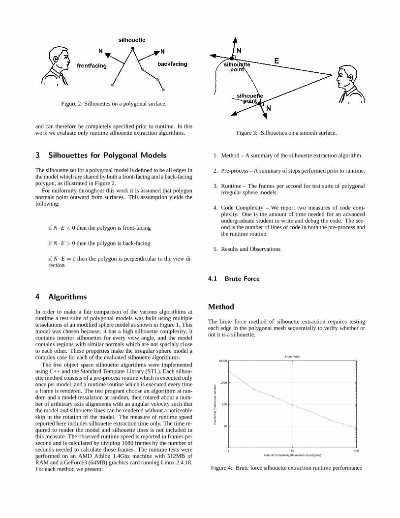
Figure 2: Silhouettes on a polygonal surface.
and can therefore be completely specified prior to runtime. In thiswork we evaluate only runtime silhouette extraction algorithms.
3 Silhouettes for Polygonal Models
The silhouette set for a polygonal model is defined to be all edges inthe model which are shared by both a front-facing and a back-facingpolygon, as illustrated in Figure 2.
For uniformity throughout this work it is assumed that polygonnormals point outward from surfaces. This assumption yields thefollowing:
if N ·E < 0 then the polygon is front-facing
if N ·E > 0 then the polygon is back-facing
if N ·E = 0 then the polygon is perpendicular to the view di-rection
4 Algorithms
In order to make a fair comparison of the various algorithims atruntime a test suite of polygonal models was built using multipletesselations of an modified sphere model as shown in Figure 1. Thismodel was chosen because; it has a high silhouette complexity, itcontains interior silhouettes for every veiw angle, and the modelcontains regions with similar normals which are not spacialy closeto each other. These properties make the irregular sphere model acomplex case for each of the evaluated silhouette algorithims.
The five object space silhouette algorithms were implementedusing C++ and the Standard Template Library (STL). Each silhou-ette method consists of a pre-process routine which is executed onlyonce per model, and a runtime routine which is executed every timea frame is rendered. The test program choose an algorithim at ran-dom and a model tessalation at random, then rotated about a num-ber of aribitrary axis alignments with an angular velocity such thatthe model and silhouette lines can be rendered without a noticeableskip in the rotation of the model. The measure of runtime speedreported here includes silhouette extraction time only. The time re-quired to render the model and silhouette lines is not included inthis measure. The observed runtime speed is reported in frames persecond and is calculated by dividing 1080 frames by the number ofseconds needed to calculate those frames. The runtime tests wereperformed on an AMD Athlon 1.4Ghz machine with 512MB ofRAM and a GeForce3 (64MB) grachics card running Linux 2.4.18.For each method we present:
Figure 3: Silhouettes on a smooth surface.
1. Method – A summary of the silhouette extraction algorithm.
2. Pre-process – A summary of steps performed prior to runtime.
3. Runtime – The frames per second for test suite of polygonalirregular sphere models.
4. Code Complexity – We report two measures of code com-plexity. One is the amount of time needed for an advancedundergraduate student to write and debug the code. The sec-ond is the number of lines of code in both the pre-process andthe runtime routine.
5. Results and Observations
4.1 Brute Force
Method
The brute force method of silhouette extraction requires testingeach edge in the polygonal mesh sequentially to verify whether ornot it is a silhouette.
1
10
100
1000
10000
1 10 100
Fra
mer
ate
(fra
mes
per
sec
ond)
Asteroid Complexity (thousands of polygons)
Brute Force
Figure 4: Brute force silhouette extraction runtime performance
Pre-Process
Create a data structure which holds the information about an edgeand contains pointers to the normal vectors of both polygons asso-ciated with that edge. Then create an edge list using a static arrayof these edge data structures.
Runtime
At runtime, for every frame, traverse the edge list. Each polygon ad-jacent to the current edge is tested to determine whether it is front-facing or back-facing with respect to the current eye point. If onepolygon is front-facing and the other back-facing a silhouette lineis rendered.
Results and Observations
There is a steep dropoff initially due to cache performance, then thebrute-force silhouette method’s runtime complexity scales linearlywith the number of edges. Because of the simplicity of the bruteforce method, it is easy to implement using a single iterative loop,thus eliminating any function call overhead.
4.2 Edge Buffer
Method
The second silhouette algorithm tested is the “edge buffer”[Buchanan and Sousa 2000]. Instead of iterating over each edgeand testing both adjacent polygon normals for front/back facing,the Edge Buffer method iterates over the polygons. Since the num-ber of polygons is always fewer than the number of edges, the edgebuffer method should run faster than the brute force algorithm.
Pre-Process
Create an edge list similar to the data structure used in the bruteforce method, adding of a front facing flag and a back facing flagfor each edge. The front facing and back facing flags for each edgeare initialized to 0. In addition, create a data structure which mapspolygons back to edges shared by the respective polygon.
Runtime
For each polygon in the polygon list, test to see whether the polygonis front-facing. If the polygon is front facing, XOR a 1 with thefront facing flag for each edge shared by that polygon. Likewise,if the polygon is back facing, XOR a 1 with the back facing flagfor each edge shared by that polygon. Upon completion, each edgethat shares exactly one front-facing polygon and one back-facingpolygon will have both flags set. Finally, iterate through the edgelist and draw only the edges that have both their flags set, also resetboth flags for all the edges to 0.
Results and Observations
In practice this implementation of the edge buffer algorithm runsslightly slower than brute force. Although the edge buffer method isless complex than brute force in terms of floating point operations,the edge buffer has a higher overhead cost because of the XOR
operations, in addition to the dot products computed to test whetherpolygons are front or back facing.
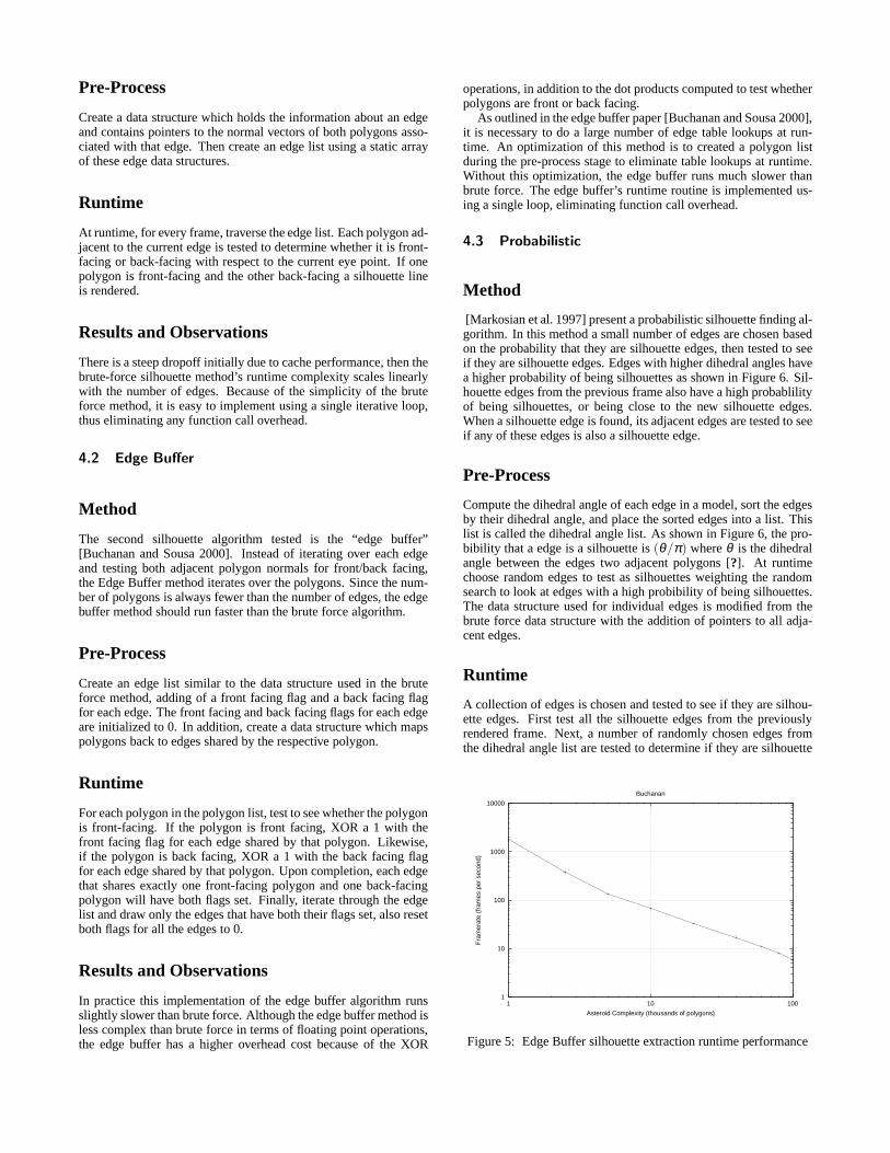
As outlined in the edge buffer paper [Buchanan and Sousa 2000],it is necessary to do a large number of edge table lookups at run-time. An optimization of this method is to created a polygon listduring the pre-process stage to eliminate table lookups at runtime.Without this optimization, the edge buffer runs much slower thanbrute force. The edge buffer’s runtime routine is implemented us-ing a single loop, eliminating function call overhead.
4.3 Probabilistic
Method
[Markosian et al. 1997] present a probabilistic silhouette finding al-gorithm. In this method a small number of edges are chosen basedon the probability that they are silhouette edges, then tested to seeif they are silhouette edges. Edges with higher dihedral angles havea higher probability of being silhouettes as shown in Figure 6. Sil-houette edges from the previous frame also have a high probablilityof being silhouettes, or being close to the new silhouette edges.When a silhouette edge is found, its adjacent edges are tested to seeif any of these edges is also a silhouette edge.
Pre-Process
Compute the dihedral angle of each edge in a model, sort the edgesby their dihedral angle, and place the sorted edges into a list. Thislist is called the dihedral angle list. As shown in Figure 6, the pro-bibility that a edge is a silhouette is(θ/π) whereθ is the dihedralangle between the edges two adjacent polygons [?]. At runtimechoose random edges to test as silhouettes weighting the randomsearch to look at edges with a high probibility of being silhouettes.The data structure used for individual edges is modified from thebrute force data structure with the addition of pointers to all adja-cent edges.
Runtime
A collection of edges is chosen and tested to see if they are silhou-ette edges. First test all the silhouette edges from the previouslyrendered frame. Next, a number of randomly chosen edges fromthe dihedral angle list are tested to determine if they are silhouette
1
10
100
1000
10000
1 10 100
Fra
mer
ate
(fra
mes
per
sec
ond)
Asteroid Complexity (thousands of polygons)
Buchanan
Figure 5: Edge Buffer silhouette extraction runtime performance

Figure 6: The small dihedral angle corresponds to a small viewarea where edge V is not a silhouette. The large dihedral anglecorresponds to a large view area where edge V is not a silhouette.Thus an edge with a smaller dihedral angle has a higher probabilityof being a silhouette edge.
edges. Each edge that is found to be a silhouette edge for the currentviewpoint is then traced.
If the edge is a silhouette, trace through the edge adjacencypointers in the dihedral angle list to check if any adjacent edges aresilhouette edges. Adjacent edges are recursively tested until thereare no adjacent silhouette edges. In order to avoid testing silhouetteedges that have already been found, a reference to each silhouetteedge is hashed into a table. Every time a new silhouette edge isfound it is checked for inclusion in this hash table. In order to avoidhaving to reset the hash table after each frame, frame numbers arestored in the hash table and compared to the current frame number.
1
10
100
1000
10000
1 10 100
Fra
mer
ate
(fra
mes
per
sec
ond)
Asteroid Complexity (thousands of polygons)
Markosian
Figure 7: Probabilistic silhouette extraction runtime performance
Results and Observations
A speedup over the brute force algorithm is observed, although asmall number of silhouette edges may be missed for a particularframe. It was observed that frame-to-frame coherence of silhouetteedges works very well, but can become more difficult as the modelbecomes large because silhouette curves tend to move across manypolygons per frame and may be missed by the tracing algorithm.For good performance scaling, the number of random edges chosenat the beginning of each frame should be proportional to the squareroot of the total number of edges.
4.4 Gauss Map Arcs
Method
A modified Gauss map can be used to calculate the silhouette edgesof a polygonal model [Gooch et al. 1999; Benichou and Elber1999]. The model is placed at the origin of a bounding sphere(Gauss map) and each edge of the model maps to an arc on thesphere. Silhouette edges are extracted from the Gauss map by in-tersecting the Gauss map with a plane. The intersecting plane isdefined as passing through a point at the origin of the boundingsphere and perpendicular to the viewing vector. The arcs on theGauss map which are intersected by the plane correspond to silhou-ette edges in the original model. Since the Gauss map only takesinto consideration the viewing direction, and not the viewing dis-tance, it will not work for perspective. A 2D Gauss map example isshown in Figure 8.
Pre-Process
Begin by mapping the model edges onto the Gauss map. Each edgein the model has two ajacent facets,F1 andF2 which have normalsN1 andN2. Model edges are mapped to the Gauss surface by plac-ing N1 and N2 at the origin of the Gauss Map and sweepingN1across the Gauss surface toN2. For a Gauss sphere,N1 and N2sweep out an arc on the surface of the sphere.
For simplicty the Gauss map can be represented as a boundingcube. With the Gauss map represented as a cube, the Gauss maparcs become straight lines on one or more of the cube faces. Eachface of the cube is divided into a 20 by 20 grid of buckets, and eachedge maps to several of these buckets, see Figure 9. After all edgeshave been mapped each bucket contains a list of zero or more edges.
Runtime
To extract the set of silhouette edges for a given viewing directiona plane is intersected with the Gauss map. The intersecting plane isdefined by a point P at the origin of the Gauss map and a vector Vwhich is the viewing direction. Since the Gauss map is representedas a grid of buckets, the intersecting plane corresponds to a list ofbuckets intersected in the Gauss map. Each bucket contains a pos-sibly empty list of edges which are silhouette edges for the currentviewing direction.
Results and Observations
This algorithm is simple to implement when the Gauss sphere isapproximated by a cube. However, the data structures used in thisalgorithim can become large depending on the bucket resolution,and this technique works only for orthogonal projection.
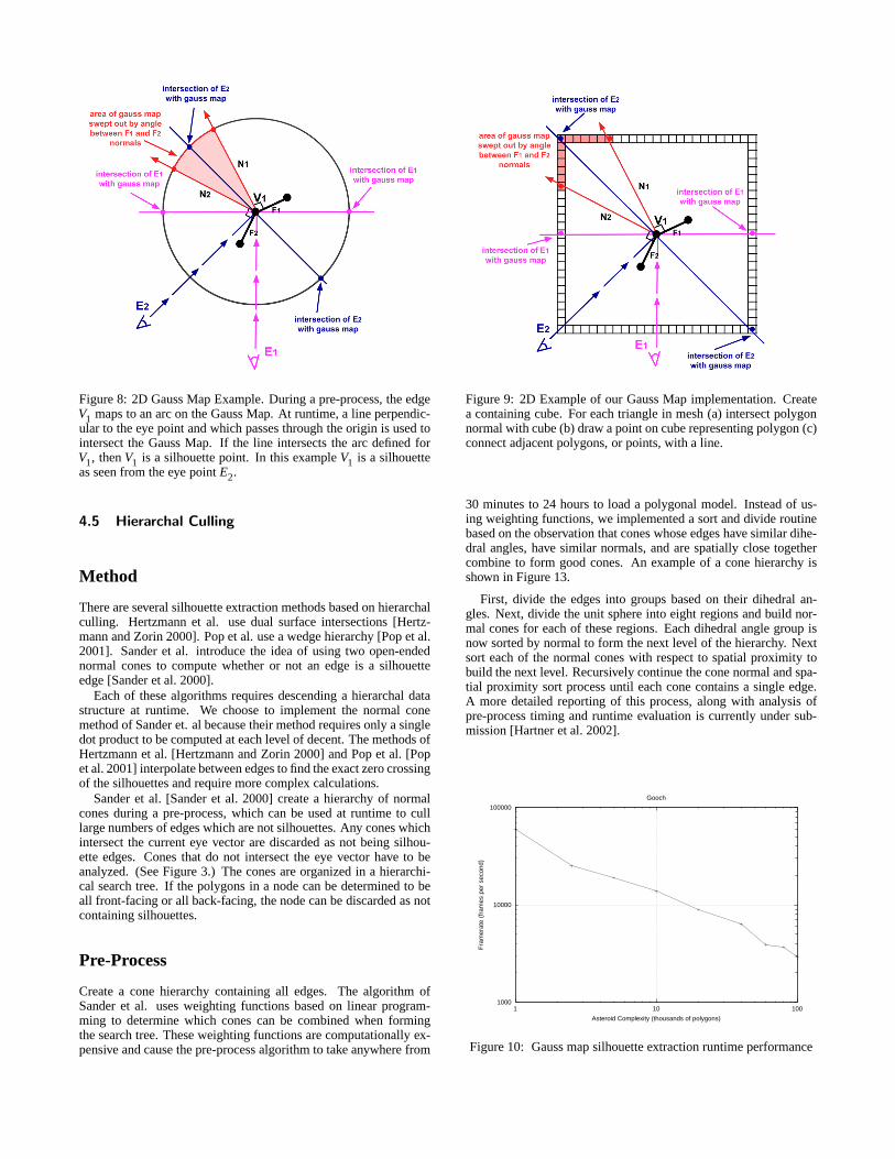
Figure 8: 2D Gauss Map Example. During a pre-process, the edgeV1 maps to an arc on the Gauss Map. At runtime, a line perpendic-ular to the eye point and which passes through the origin is used tointersect the Gauss Map. If the line intersects the arc defined forV1, thenV1 is a silhouette point. In this exampleV1 is a silhouetteas seen from the eye pointE2.
4.5 Hierarchal Culling
Method
There are several silhouette extraction methods based on hierarchalculling. Hertzmann et al. use dual surface intersections [Hertz-mann and Zorin 2000]. Pop et al. use a wedge hierarchy [Pop et al.2001]. Sander et al. introduce the idea of using two open-endednormal cones to compute whether or not an edge is a silhouetteedge [Sander et al. 2000].
Each of these algorithms requires descending a hierarchal datastructure at runtime. We choose to implement the normal conemethod of Sander et. al because their method requires only a singledot product to be computed at each level of decent. The methods ofHertzmann et al. [Hertzmann and Zorin 2000] and Pop et al. [Popet al. 2001] interpolate between edges to find the exact zero crossingof the silhouettes and require more complex calculations.
Sander et al. [Sander et al. 2000] create a hierarchy of normalcones during a pre-process, which can be used at runtime to culllarge numbers of edges which are not silhouettes. Any cones whichintersect the current eye vector are discarded as not being silhou-ette edges. Cones that do not intersect the eye vector have to beanalyzed. (See Figure 3.) The cones are organized in a hierarchi-cal search tree. If the polygons in a node can be determined to beall front-facing or all back-facing, the node can be discarded as notcontaining silhouettes.
Pre-Process
Create a cone hierarchy containing all edges. The algorithm ofSander et al. uses weighting functions based on linear program-ming to determine which cones can be combined when formingthe search tree. These weighting functions are computationally ex-pensive and cause the pre-process algorithm to take anywhere from
Figure 9: 2D Example of our Gauss Map implementation. Createa containing cube. For each triangle in mesh (a) intersect polygonnormal with cube (b) draw a point on cube representing polygon (c)connect adjacent polygons, or points, with a line.
30 minutes to 24 hours to load a polygonal model. Instead of us-ing weighting functions, we implemented a sort and divide routinebased on the observation that cones whose edges have similar dihe-dral angles, have similar normals, and are spatially close togethercombine to form good cones. An example of a cone hierarchy isshown in Figure 13.
First, divide the edges into groups based on their dihedral an-gles. Next, divide the unit sphere into eight regions and build nor-mal cones for each of these regions. Each dihedral angle group isnow sorted by normal to form the next level of the hierarchy. Nextsort each of the normal cones with respect to spatial proximity tobuild the next level. Recursively continue the cone normal and spa-tial proximity sort process until each cone contains a single edge.A more detailed reporting of this process, along with analysis ofpre-process timing and runtime evaluation is currently under sub-mission [Hartner et al. 2002].
1000
10000
100000
1 10 100
Fra
mer
ate
(fra
mes
per
sec
ond)
Asteroid Complexity (thousands of polygons)
Gooch
Figure 10: Gauss map silhouette extraction runtime performance

Figure 11: A dolphin model in which a cone is associated withsome of the polygon edges. (a) view from which marked polygonsare not silhouettes (b) view from which marked polygons must betested
Runtime
During runtime, traverse the cone hierarchy testing cones to find ifthey include the current eye vector. This test can be done with twodot products:
The eye vector is inside the cone if(E−O) · (N) >= 0 and((E−O) · (N))2 >= ||E−O||2Where E is the vector form the eyepoint as in 2, O
is the cone origin and N is the scaled cone normalN =coneNormal/cos(coneAngle). If a cone contains the eye point, wecan discard it and all its sub-cones. Otherwise we traverse down thecone hierarchy until we are left with only edges. Each edge that isnot culled at this point must be checked individually to determinewhether or not it is a silhouette edge.
Results and Observations
A significant improvement in runtime speed for silhouette extrac-tion is observed using this method. Because cone hierarchy is con-structed using a top-down approach, alternating grouping normalsby angle and by distance, edges become closer together both interms of edge normal and spatial locality at each level of the hierar-chy.
10
100
1000
10000
1 10 100
Fra
mer
ate
(fra
mes
per
sec
ond)
Asteroid Complexity (thousands of polygons)
Sander
Figure 12: Hierarchal Culling silhouette extraction runtime perfor-mance
Figure 13: Example of a cone hierarchy built from cones that havesimilar dihedral angles, have similar cone normals, and are spatiallyclose to each other.
5 Discussion and Future Work
We found that for small models, under 10,000 polygons for ourhardware, brute force silhouette extraction is easy to implement andruns nearly as fast much more complex methods. For more com-plex models it may be worth the time implementing more complexmethods. If orthographic is all that is needed, then Gauss Mapsare easiest to implement and also very fast. For large models withperspective, methods based upon heirarchical culling may be nec-essary, but are generally difficult to program. Memory managementseems to be more important than the algorithmn. All of the methodsscale at the same rate as soon as cache misses begain to occur.
We found that silhouette extraction methods are more sensitiveto size than to complexity in the polygonal models. In all of thetests performed model size dominated the runtime speed of the al-gorithims. We tested the algorithims on the complexity based testsuite of Kettner and Welzl [Kettner and Welzl 1997] we found nosignificant difference in the runtime of the algorithims on mod-els of differing complexity but with similar polygon counts. Thismay be due to the fact that all of the models in the Kettner andWelzl test suite have less than 15,000 polygons. The complexitybased model test suite is available online at:www.cs.unc.edu/ ket-tner/proj/obj3d/index.html
The algorithms reviewed in this paper represent the current bestin the field. However, an ideal silhouette extraction algorithm hasyet to be found. Some desirable characteristics for an ideal silhou-ette algorithm are given below.
The ability to handle non-closed models and multiple objects.
The ability to perform visability culling on the extracted sil-houette set.
The ability to perform occlusion clipping on the extracted sil-houette set.
The ability to simplifiy coincident silhouette edges, i.e. edgeswhich overlap or occlude each other when projected to screenspace.
6 Acknowledgements
We would like to thank Aaron Hertzmann for sharing his code withus. We would also like to thank Peter Pike Sloan, Amy Gooch, LeeMarkosian, Mario Costa Sousa, Gershon Elber and Adam Finkel-sein for their time and consideration in talking with us and answer-ing our many questions on this project. We would also like to thankAmy Gooch for her help in constructing models.
Thanks to Alias|Wavefront for their generous donation of MayaComplete, which we used to create the geometric models for thispaper.
References
BENICHOU, F., AND ELBER, G. 1999. Output sensitive extractionof silhouettes from polygonal geometry. InPacific Graphics ’99.
BOTTINO, A., AND LAURENTINI , A. 2001. Experimenting withnonintrusive motion capture in a virtual environment.The VisualComputer 17, 1, 14–29. ISSN 0178-2789.
BUCHANAN, J. W.,AND SOUSA, M. C. 2000. The edge buffer:A data structure for easy silhouette rendering. InNPAR 2000 :First International Symposium on Non Photorealistic Animationand Rendering, ACM SIGGRAPH / Eurographics, 39–42.
CHUNG, Y. C., PARK, J. W., SHIN, H., AND CHOI, B. K. 1998.Modeling the surface swept by a generalized cutter for nc verifi-cation.Computer-aided Design 30, 8, 587–594.
FUA, P., PLANKERS, R., AND THALMANN , D. 1999. Fromsynthesis to analysis: Fitting human animation models to imagedata. InComputer Graphics International ’99, IEEE CS Press.ISBN ISBN 0-7695-018.
GOOCH, B., SLOAN, P.-P. J., GOOCH, A., SHIRLEY, P. S.,ANDRIESENFELD, R. 1999. Interactive technical illustration. In1999 ACM Symposium on Interactive 3D Graphics, ACM SIG-GRAPH, 31–38. ISBN 1-58113-082-1.
HAINES, E. 2001. Soft planar shadows using plateaus.Journal ofGraphics Tools 6, 1, 19–27.
HARTNER, A., HARTNER, M., COHEN, E., AND GOOCH, B.2002. A fast method for normal cone hierarchy construction.Submitted to The Journal of Graphics Tools.
1
10
100
1000
10000
100000
1 10 100
Fra
mer
ate
(fra
mes
per
sec
ond)
Asteroid Complexity (thousands of polygons)
composite
goochsander
markosianbrute
buchanan
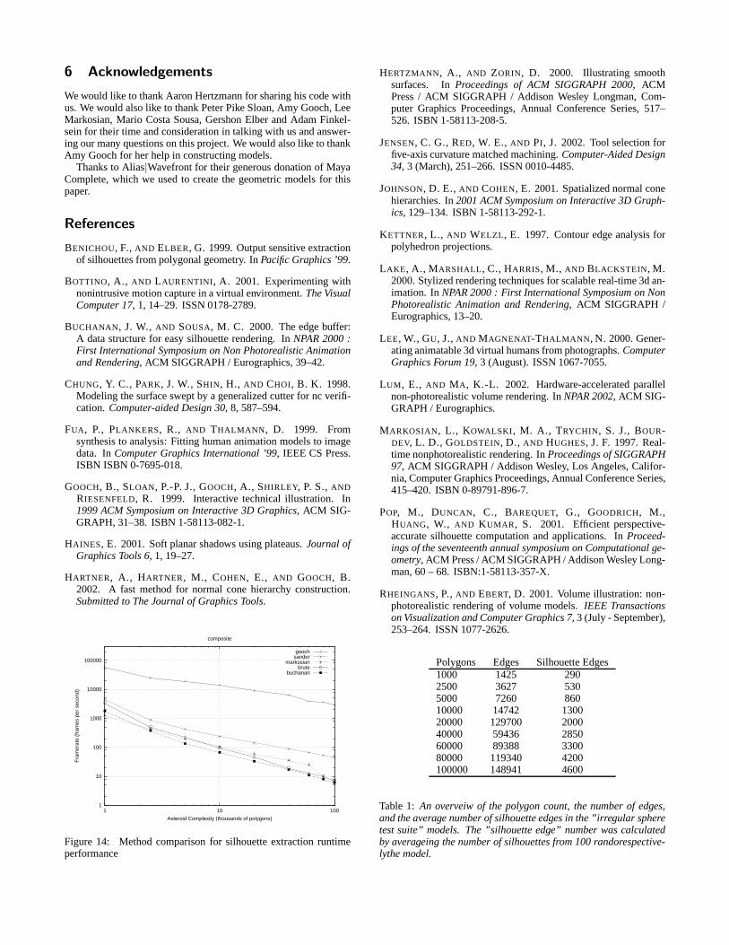
Figure 14: Method comparison for silhouette extraction runtimeperformance
HERTZMANN, A., AND ZORIN, D. 2000. Illustrating smoothsurfaces. InProceedings of ACM SIGGRAPH 2000, ACMPress / ACM SIGGRAPH / Addison Wesley Longman, Com-puter Graphics Proceedings, Annual Conference Series, 517–526. ISBN 1-58113-208-5.
JENSEN, C. G., RED, W. E., AND PI, J. 2002. Tool selection forfive-axis curvature matched machining.Computer-Aided Design34, 3 (March), 251–266. ISSN 0010-4485.
JOHNSON, D. E.,AND COHEN, E. 2001. Spatialized normal conehierarchies. In2001 ACM Symposium on Interactive 3D Graph-ics, 129–134. ISBN 1-58113-292-1.
KETTNER, L., AND WELZL, E. 1997. Contour edge analysis forpolyhedron projections.
LAKE, A., MARSHALL, C., HARRIS, M., AND BLACKSTEIN, M.2000. Stylized rendering techniques for scalable real-time 3d an-imation. InNPAR 2000 : First International Symposium on NonPhotorealistic Animation and Rendering, ACM SIGGRAPH /Eurographics, 13–20.
LEE, W., GU, J.,AND MAGNENAT-THALMANN , N. 2000. Gener-ating animatable 3d virtual humans from photographs.ComputerGraphics Forum 19, 3 (August). ISSN 1067-7055.
LUM, E., AND MA, K.-L. 2002. Hardware-accelerated parallelnon-photorealistic volume rendering. InNPAR 2002, ACM SIG-GRAPH / Eurographics.
MARKOSIAN, L., KOWALSKI, M. A., TRYCHIN, S. J., BOUR-DEV, L. D., GOLDSTEIN, D., AND HUGHES, J. F. 1997. Real-time nonphotorealistic rendering. InProceedings of SIGGRAPH97, ACM SIGGRAPH / Addison Wesley, Los Angeles, Califor-nia, Computer Graphics Proceedings, Annual Conference Series,415–420. ISBN 0-89791-896-7.
POP, M., DUNCAN, C., BAREQUET, G., GOODRICH, M.,HUANG, W., AND KUMAR, S. 2001. Efficient perspective-accurate silhouette computation and applications. InProceed-ings of the seventeenth annual symposium on Computational ge-ometry, ACM Press / ACM SIGGRAPH / Addison Wesley Long-man, 60 – 68. ISBN:1-58113-357-X.
RHEINGANS, P.,AND EBERT, D. 2001. Volume illustration: non-photorealistic rendering of volume models.IEEE Transactionson Visualization and Computer Graphics 7, 3 (July - September),253–264. ISSN 1077-2626.
Polygons Edges Silhouette Edges1000 1425 2902500 3627 5305000 7260 86010000 14742 130020000 129700 200040000 59436 285060000 89388 330080000 119340 4200100000 148941 4600
Table 1: An overveiw of the polygon count, the number of edges,and the average number of silhouette edges in the ”irregular spheretest suite” models. The ”silhouette edge” number was calculatedby averageing the number of silhouettes from 100 randorespective-lythe model.
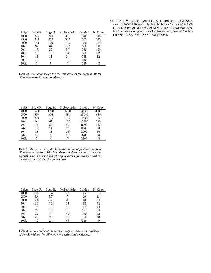
Polys Brute F. Edge B. Probabilistic G. Map N. Cone1000 326 320 336 340 3482500 325 315 332 335 3455000 194 129 185 330 33510k 92 64 103 330 21020k 45 32 57 330 12940k 19 16 34 330 8260k 13 11 24 315 6280k 10 8 10 310 51100k 7 6 7 310 42
Table 2: This table shows the the framerate of the algorithims forsilhouette extraction and rendering.
Polys Brute F. Edge B. Probabilistic G. Map N. Cone1000 3400 1790 1250 60000 46002500 500 376 430 25000 8805000 220 135 195 19000 42210k 94 67 106 13800 24020k 45 33 59 8900 14240k 19 17 36 6300 8860k 13 11 25 3900 6680k 10 8 10 3700 54100k 7 6 7 2900 44
Table 3: An overveiw of the framerate of the algorithims for onlysilhouette extraction. We show these numbers because silhouettealgorithims can be used in haptic applicaitons, for example, withoutthe need to render the silhouette edges.
Polys Brute F. Edge B. Probabilistic G. Map N. Cone1000 5.8 5.4 6.1 15 5.82500 6.4 5.7 7 29 6.45000 7.6 6.2 8. 48 7.410k 9.7 7.2 11 62 9.620k 14 9.1 18 103 1440k 23 13 30 133 2460k 32 17 42 160 3280k 40 20 55 190 40100k 49 24 68 219 49
Table 4:An overveiw of the memory requiernments, in megabytes,of the algorithims for silhouette extraction and rendering.
SANDER, P. V., GU, X., GORTLER, S. J., HOPPE, H., AND SNY-DER, J. 2000. Silhouette clipping. InProceedings of ACM SIG-GRAPH 2000, ACM Press / ACM SIGGRAPH / Addison Wes-ley Longman, Computer Graphics Proceedings, Annual Confer-ence Series, 327–334. ISBN 1-58113-208-5.