Embed Size (px)
DESCRIPTION
Object-Oriented Modeling and Design. Object-Oriented models are useful for :. understanding problems communicating with application experts modeling enterprises preparing documentation. What is Procedure-Oriented Programming ?. Emphasis is on doing things (algorithms) - PowerPoint PPT Presentation
Citation preview
Object-Oriented Object-Oriented Modeling and DesignModeling and Design
•understanding problems
•communicating with application experts
•modeling enterprises
•preparing documentation
Object-Oriented models are useful for :
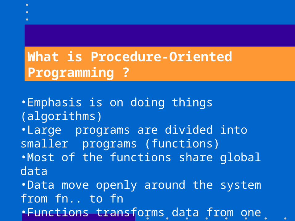
•Emphasis is on doing things (algorithms)•Large programs are divided into smaller programs (functions)•Most of the functions share global data•Data move openly around the system from fn.. to fn•Functions transforms data from one form to another•Employs top-down approach in program design
What is Procedure-Oriented Programming ?
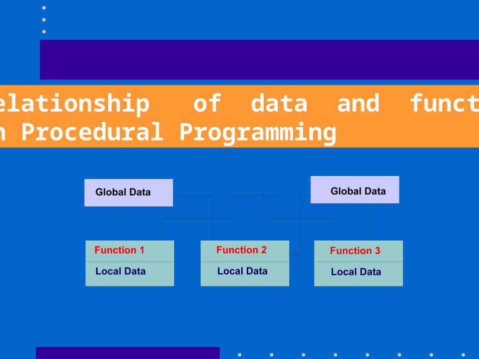
Relationship of data and functionsin Procedural Programming
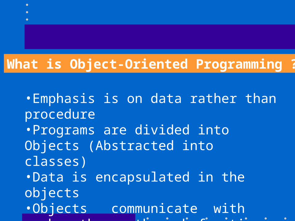
What is Object-Oriented Programming ?
•Emphasis is on data rather than procedure•Programs are divided into Objects (Abstracted into classes)•Data is encapsulated in the objects •Objects communicate with each other through functions•Follows bottom-up approach in program design.
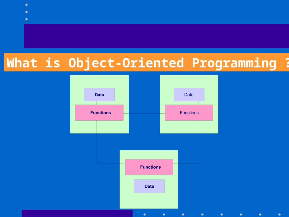
What is Object-Oriented Programming ?
Characteristics of Object-Oriented Model
•Abstraction•Encapsulation•Polymorphism•Inheritance
Abstraction
•Focus is an what an Object is and does before deciding how it should be implemented.
•Use of abstraction preserves the freedom to make decisions as long as possible by avoiding premature commitments to details.
Encapsulation
•Separates the external aspects of an object, which are accessible to other objects, from the internalimplementation details of the object.•Prevents a program from becoming so inter-dependent that a small change has massive ripple effects.
Polymorphism
•The same operation may behave differently on different classes.•An operation is an action or transformation that an object performs or is subject to.Example : 'move' operation may behave differently on the Window and Chess Piece Classes.
Inheritance
•Is the sharing of attributes and operations among classes based on a hierarchical relationship. •The properties of a Superclass need not be repeated in the subclass. Example : Scrolling Window and Fixed Window are subclasses of Superclass Window.
OBJECT MODELING CONCEPTS
An Object Model
•captures the static structure of the systemshows the objects, the relationship between them,and •the attributes and operations that characterize each class of objects.
Objectsis a concept, abstraction, or thing with crisp boundaries and meaning for an application. Purpose
promotes understanding of the real world provides a practical basis for computer information.
Objects have identity and are distinguishable. Example : Two apples with the same color, shape and texture are still individual entities.
ClassesIt describes a group of objects, with common attributes, operations and semantics. Example : Fruit is a class.
Objects in a class have the same attributes and behaviour patterns. A object's class is an implicit property of the object.
OBJECT DIAGRAMS
•Object Diagrams provides a formal graphic notation for modeling objects, classes and their relationships to one another. •They are concise and easy to understand.
OBJECT DIAGRAMS
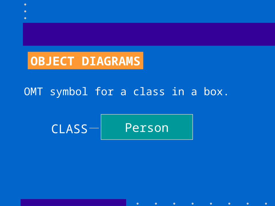
OMT symbol for a class in a box.
CLASS Person
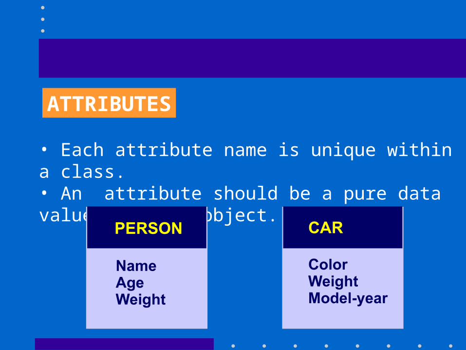
ATTRIBUTES
•is a property of the objects in a class
•is a data value held by the objects in a class
•different Object instances may have the same or different values for a given attribute.
ATTRIBUTES
• Each attribute name is unique within a class.• An attribute should be a pure data value, not an object.
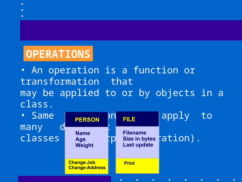
OPERATIONS• An operation is a function or transformation that may be applied to or by objects in a class.• Same operations may apply to many different
classes (Polymorphic Operation).
Methods
is the implementation of an operation for a class.
Example : Operation 'Print' in class 'File' can be implemented for printing ASCII files, printing binary files are for printing digitized picture files.
Links and Associations
A link is a physical or conceptual connection object instances i.e. represents the relationship between them.
Example : Joe Smith works for Simplex Company
Links and Associations
• An association describes a group of links with common structure and common semantics.
Example : A persons works for a company.
• Association and links often appear as verbs in the problem statement.
Representation of Links / Associations
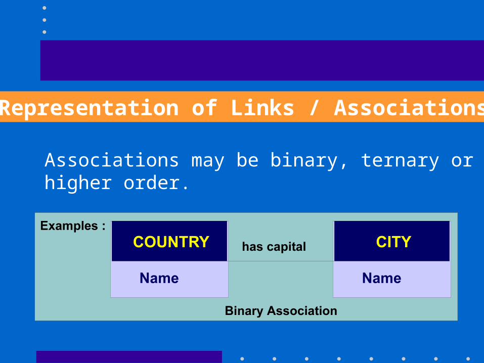
Associations may be binary, ternary or higher order.
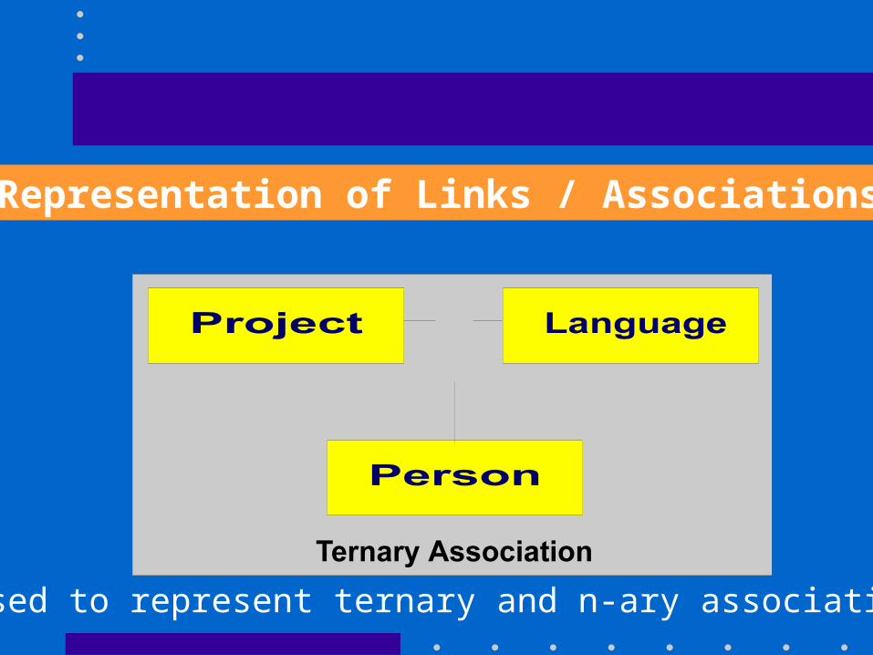
Representation of Links / Associations
used to represent ternary and n-ary association.
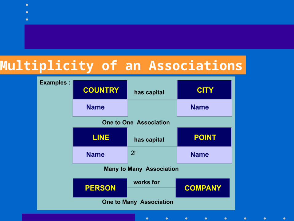
Multiplicity of an Associations
• Specifies how many instances of one class may to a single instance of an associated class. • Usually described as "one" or "many".
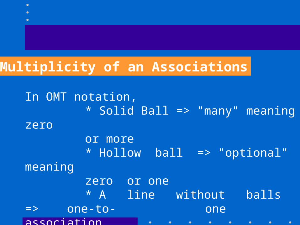
Multiplicity of an Associations
In OMT notation, * Solid Ball => "many" meaning zero or more* Hollow ball => "optional" meaning zero or one * A line without balls => one-to-one association.
Multiplicity of an Associations
Link and Association Concepts
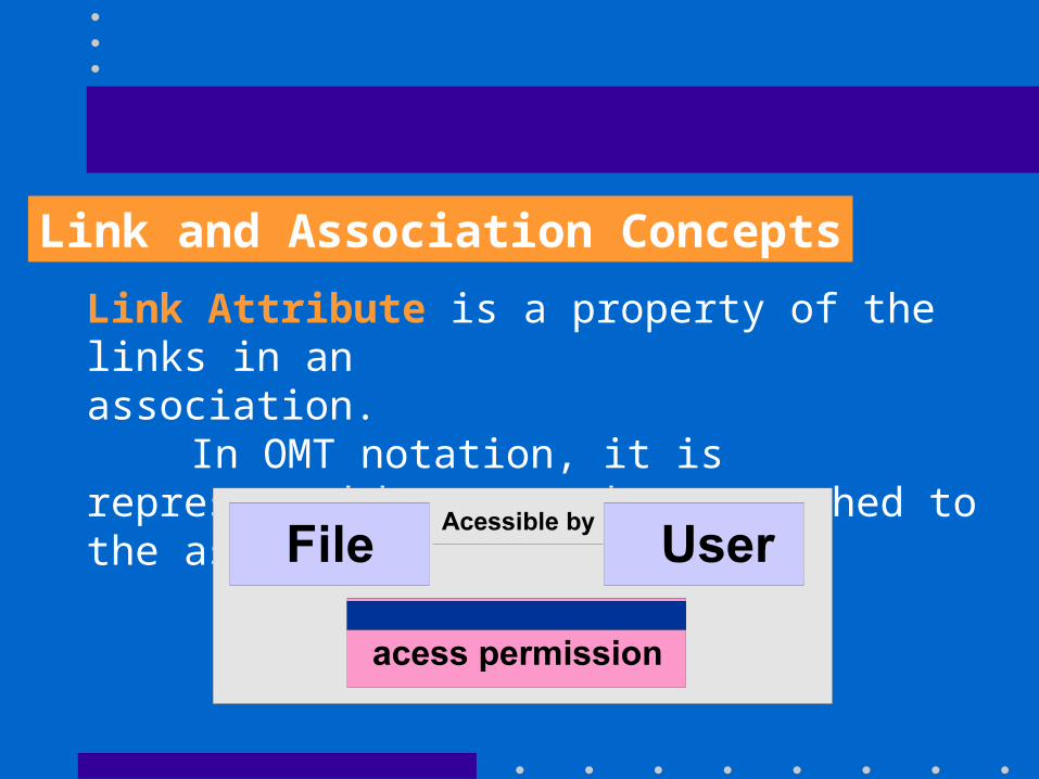
Link Attribute is a property of the links in an association.
In OMT notation, it is represented by a box attached to the association by a loop.
Link and Association Concepts
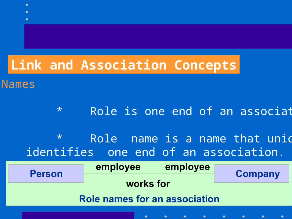
Role Names * Role is one end of an association. * Role name is a name that uniquely
identifies one end of an association.
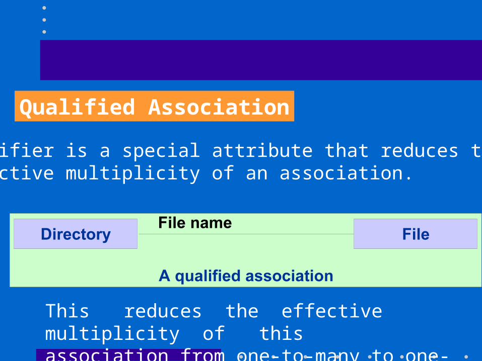
Qualified Association
Qualifier is a special attribute that reduces the effective multiplicity of an association.
This reduces the effective multiplicity of this association from one-to-many to one-to-one.
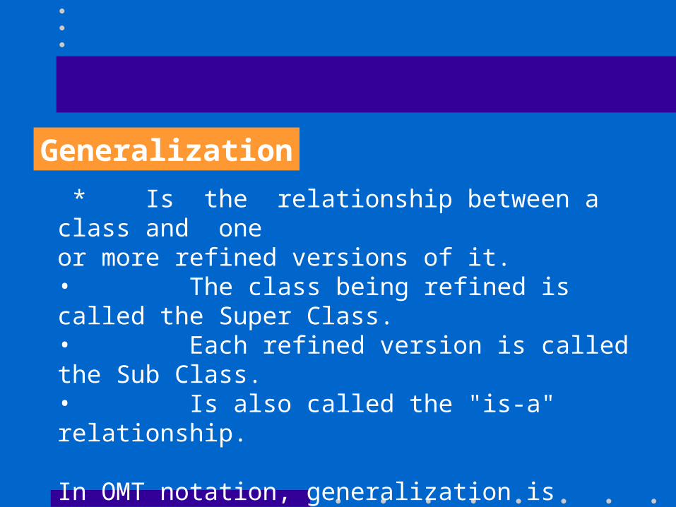
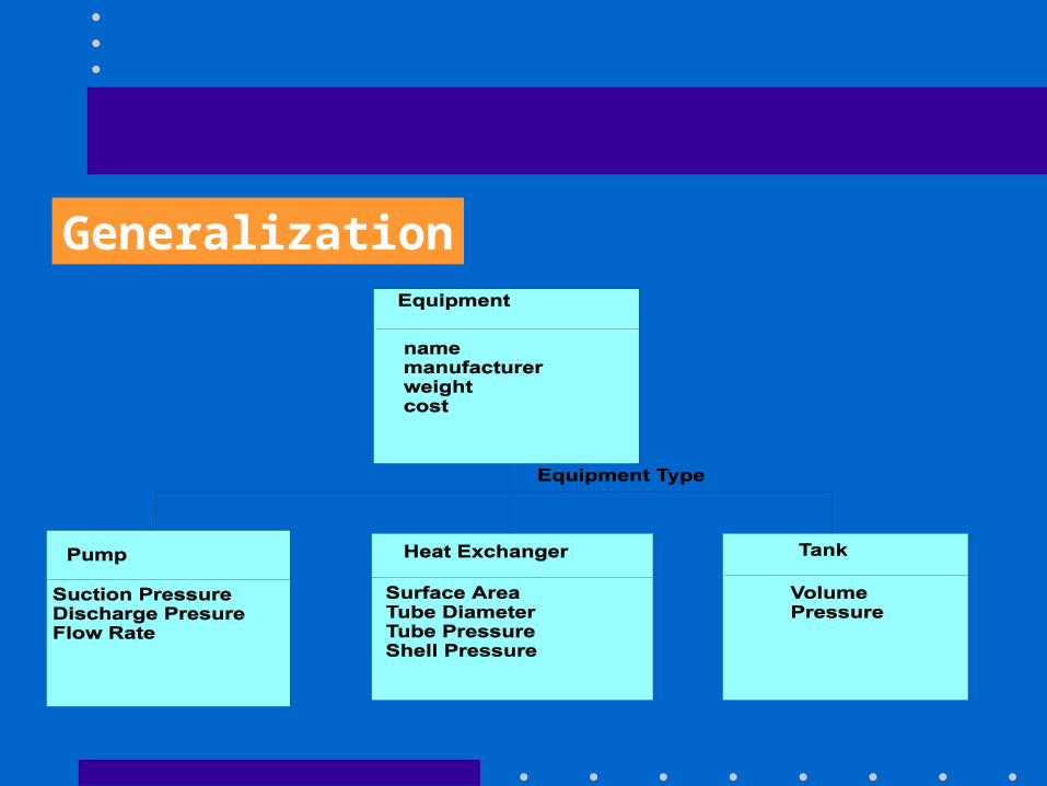
Generalization
* Is the relationship between a class and one or more refined versions of it. • The class being refined is called the Super Class. • Each refined version is called the Sub Class. • Is also called the "is-a" relationship.
In OMT notation, generalization is represented by a triangle connection a superclass to its subclass.
Generalization
Inheritance
• Each subclass is said to inherit the
features of its superclass.
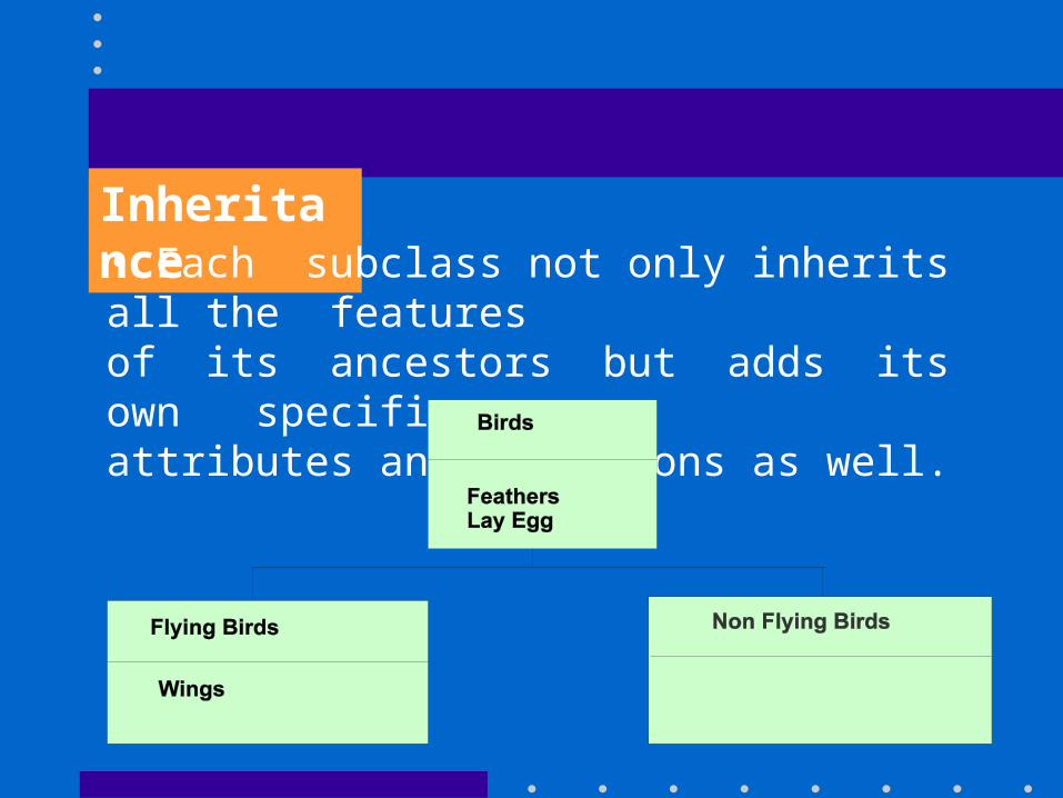
Inheritance• Each subclass not only inherits all the features
of its ancestors but adds its own specific attributes and operations as well.
Inheritance
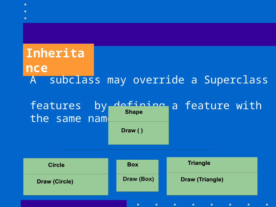
A subclass may override a Superclass features by defining a feature with the same name.
Multiple Inheritance
• A class may have more than one superclass and inherits features from all panels
• Such a class is called a "Join Class".
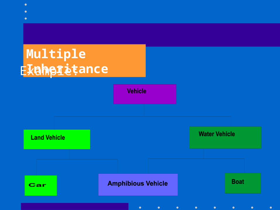
Multiple InheritanceExample:
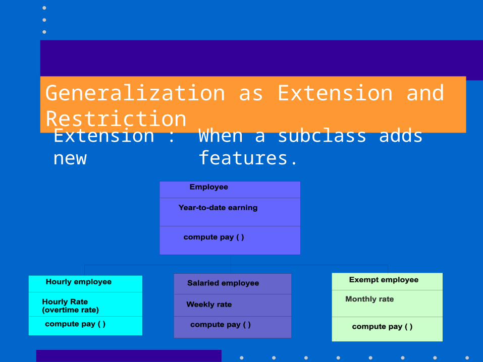
Generalization as Extension and RestrictionExtension : When a subclass adds new
features.
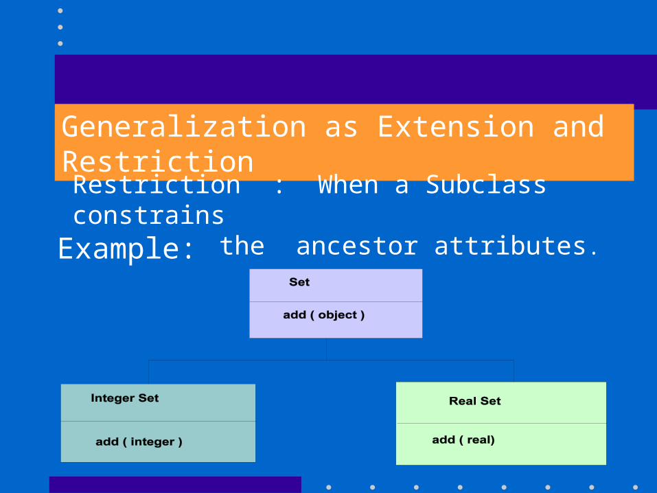
Generalization as Extension and RestrictionRestriction : When a Subclass constrains
the ancestor attributes. Example:
Generalization, Inheritance and Specialization
• Generalization is the relationship among classes.
• Inheritance is the mechanism of sharing attributes and operations using the generalization relationship.
Generalization and Inheritance:
Generalization, Inheritance and Specialization
Generalization and Specialization:
(Basically they are two different viewpoints of the same relationship)
•Generalization => Superclass generalizes the subclass.
•Specialization => Subclass refines or Specializes the Superclass.
Aggregation:
• Is the "part-whole" or "a-part-of" relationship
• Objects representing the components are associated with an object representing the entire assembly. • Aggregation is a special form of association.
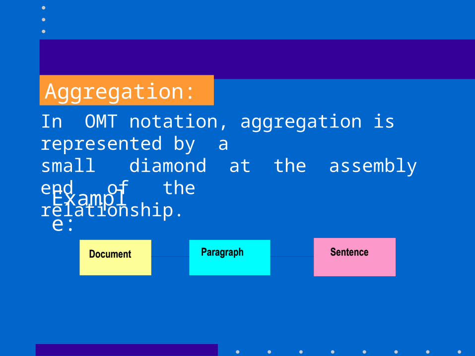
Aggregation:In OMT notation, aggregation is represented by a small diamond at the assembly end of the relationship.
Example:
Aggregation Versus Generalization
Aggregation relates instances
• two distinct parts are involved, one is a part of the other.
Generalization relates classes
• Subclass inherits the properties of theSuperclass.
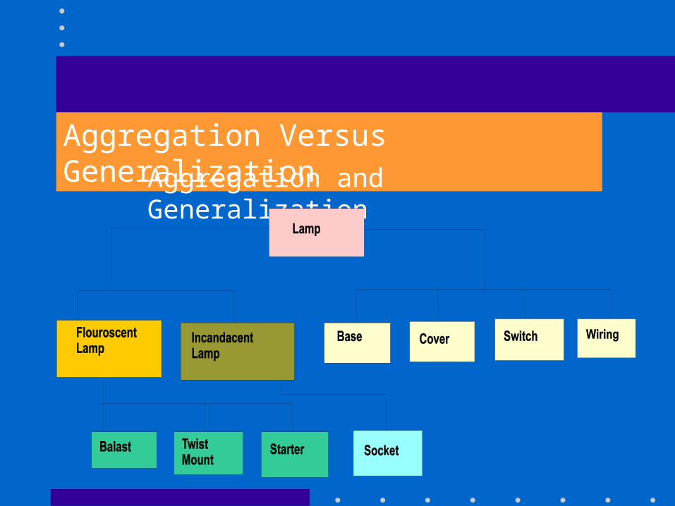
Aggregation Versus GeneralizationAggregation and Generalization
ABSTRACT CLASSES
• An abstract class is a class that has no direct
instances but whose descendent classes have direct
instances.
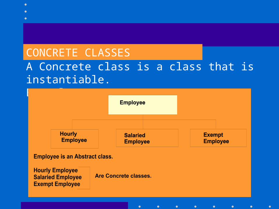
CONCRETE CLASSES A Concrete class is a class that is instantiable.Example:
META DATA
• Is data that describes other data
• Many real-world applications have metadata such
as pats catalogs, blueprints and dictionaries. Example : The definition of a class is metadata.
META DATA
• In RDBMS, a data table may store information such as capital of India is New Delhi.
Capital of Japan is Tokyo. And so on .…
A meta table will store the fact that a country has a Capital City.
Homomorphisms
• Is the mapping between two associations.
• A frequent usage is the mapping between a descriptor and a part tree
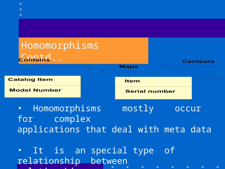
Homomorphisms Contd..
• Homomorphisms mostly occur for complex applications that deal with meta data
• It is an special type of relationship between relationships.
Dynamic Modeling
• examines changes to the objects and their relationships overtime.
• represents control information : The sequence of events, states and operations that occur within a system of objects.
• describes the sequences of operations that occur in response to external stimuli.
• represents the control structure of a system.
Events and States
• State is the attribute values and links held by an object
•An event results in a series of changes to the object states.
•The pattern of events, states and state transitions for a given class can be abstracted and represented as a state diagram.
Events
• Is something that happens at a point in time
• Is a one-way transmission of information from one object to another.
• Events may be simple signals, or may convey data values. • Events with common structure and behaviour can be grouped into an Event class.
• Events includes error conditions too.
Events Contd..Example:
•airplane flight departs
• mouse button pushed
• input string entered
• phone receiver lifted
Scenarios
• Scenario is a sequence of events that occurs during one particular execution of a system.
• Scenario can be the historical record of executing a system.
• Scenario can be a thought experiment of executing a proposed system.
Scenarios Contd..Example : Scenario for making a telephone call.
•caller lifts receiver•dial tone begins•caller dials digits•called phone begins ringing•called party picks up the receiver•phones are connected•caller hangs up•phones are disconnected.
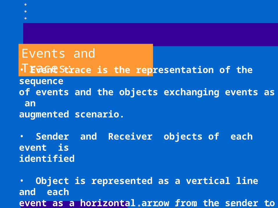
Events and Traces:• Event trace is the representation of the sequence of events and the objects exchanging events as an augmented scenario.
• Sender and Receiver objects of each event is identified
• Object is represented as a vertical line and each event as a horizontal arrow from the sender to the receiver object.
• Sequence of events is important.
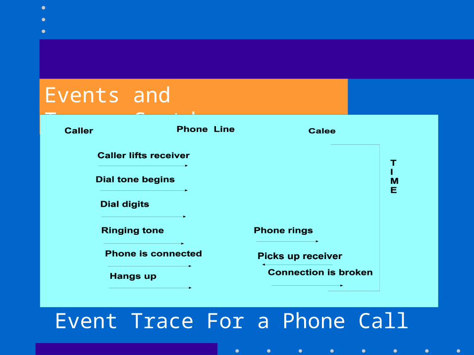
Events and Traces:Contd..
Event Trace For a Phone Call
State:
•Is an abstraction of the attribute values and links of an object.
•A state specifies the response of the object to input events. •The response of an object to an event may include an action or a change of state by the objects.
Example : After the receiver is lifted and before the first digit is dialed, the phone line is in state Dial tone.
State Diagrams• It relates events and states
• It is a graph whose nodes are states and whose directed arcs are transitions labelled by event names.
• Describes the behaviour of a single class of objects
• Example : State diagram for phone line
Figure 5.5 Page 90 (Rambaugh)
Relationship between Object and Dynamic Models
• The dynamic model structure is relatedto and constrained by Object model structure.
•A sub-state refines the attribute and link values that the object can have.
• The dynamic model specifies allowable sequences of changes to objects from the object model.
Functional Modeling
•Describes computations within a system. •It shows how output values in a computation are derived from input values, without regard for the order in which the values are computed. •Consists of multiple DFD's, which show the flow of values from external inputs, through operations and internal data stores, to external outputs.
Data Flow Diagrams (DFD's)
•Shows the functional relationships of values computed by a system, including input values and output values and internal data stores. •A data flow diagram is a graph showing the flow of data values from their sources in objects through processes that transform them to their destinations in other objects. •It does not show central information.
DFD's Contd..
A DFD contains
• processes, that transform data
• data flows, that move data
• actor objects, that produce and consume data
• data store objects that store data passively.
Processes
• A process transforms data values. • The final model only indicates the possible functional paths, it does not show which path will actually occur.
Processes
•The results of such a process depends on the behaviour of the system, as specified by the dynamic model.
•Process may or may not have side effects on the non-functional components such as data stores and external objects.
Processes Contd..
•Representation in DFD is as an ellipse, containing a description of the transformation.
•Each process has a fixed number of input and output data arrows.
•Input and Outputs are labeled.
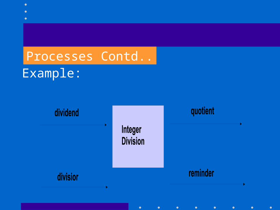
Processes Contd..Example:
Data Flows
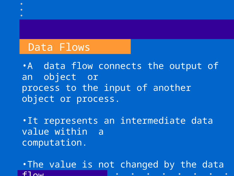
•A data flow connects the output of an object or process to the input of another object or process.
•It represents an intermediate data value within a computation.
•The value is not changed by the data flow.
Data Flows Contd..
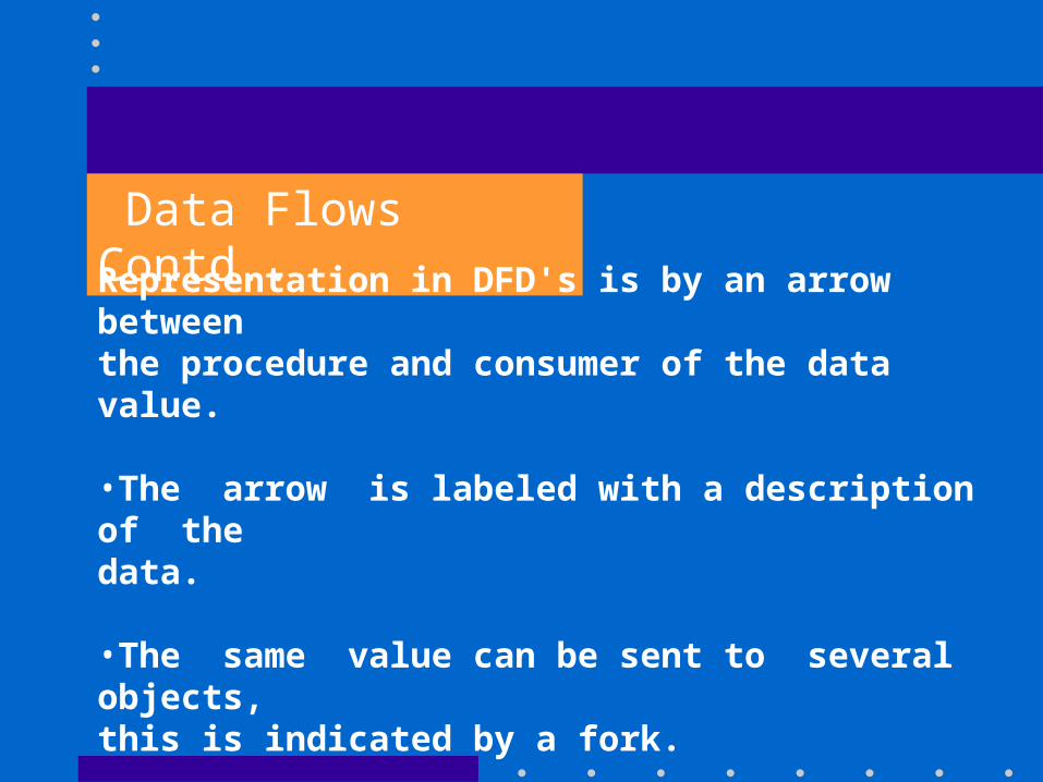
Representation in DFD's is by an arrow between the procedure and consumer of the data value.
•The arrow is labeled with a description of the data. •The same value can be sent to several objects, this is indicated by a fork.
•Output arrows if not split into its components, may be unlabeled.
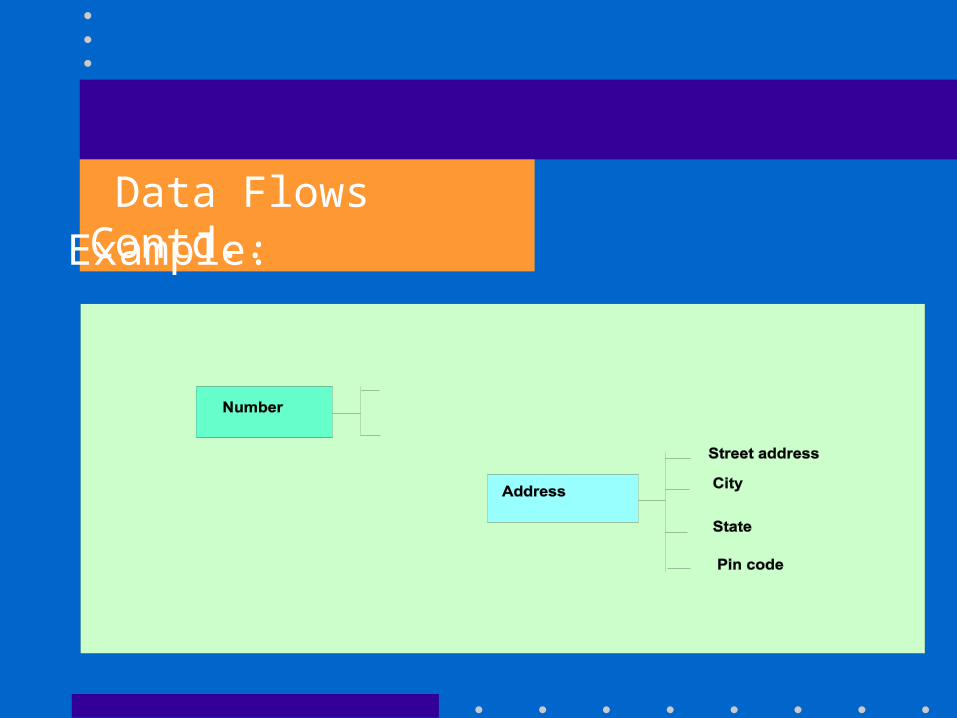
Data Flows Contd..Example:
Actors
•An actor is an active object that drives the data flow graph by producing or consuming values. •Actors are attached to the inputs and outputs of a data flow graph.
•Actors act as sources and sinks of data, so also called as terminators. •Actors lie on the boundary of the data flow graph but terminate the flow of data.
Actors Contd..
•Representation in DFD's is by a rectangle
•Arrows between the actor and the diagram are inputs and outputs of the diagram.
•Actions of actors are a part of the Dynamic Model.

Actors Contd..
•Representation in DFD's is by a rectangle
•Arrows between the actor and the diagram are inputs and outputs of the diagram.
•Actions of actors are a part of the Dynamic Model.
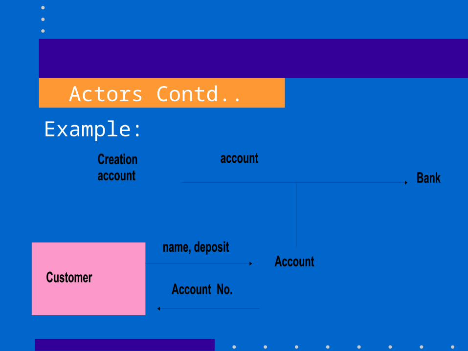
Actors Contd..
Example:
Data Stores
• A data store is a passive object within a data flow diagram, that stores data for later access.
• A data store does not generate any operations on its own but merely responds to requests to store and access data.
Data Stores Contd..
• A data store allows values to be accessed in a different order, than they are generated.
• Aggregate data stores, such as lists and labels, provide access of data by insertion order or index keys.
• Representation of a data store is by a pair of parallel lines containing the name of the store.
Data Stores Contd..
• Input arrows indicate information or operations that modify the stored data (like adding, modifying, deleting elements)
• Output arrows indicate information retrieved from the data store the data store
Data Stores Contd..
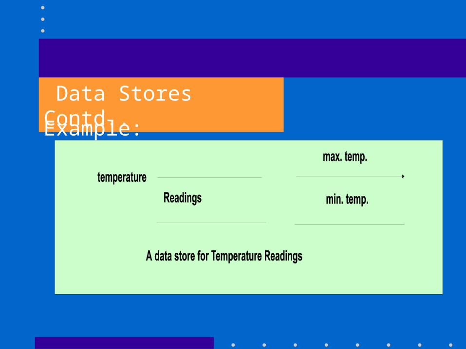
Example:
Relationship between Object, Dynamic and Functional Models
•Functional model shows what "has to be done" by a system
•Object model shows the "doer" - the objects of the system.
•Dynamic model shows the sequence in which the operations are performed.
•Processes in the final model shows objects that are related by functions.
Relative to the Functional Model
• The Object Model shows the structure of the actors, data stores, and flows in the functional model.
• The Dynamic Model shows the sequence in which processes are performed.
Relative to the Object Model
•The final model shows the operations in the classes and the arguments of each operation.
•The Dynamic Model shows the states of each object and the operations that are performed as it receives events and changes state.
Relative to Dynamic Model
The final Model shows the definitions of the leaf actions and activities that are undefined with the dynamic model.
The Object Model shows what changes state and undergoes operations.
OBJECT ORIENTED ANALYSIS (OOA)
Stages in OOA
Problem / Requirement is stated
•Problem / Requirement is understood
•Essential features are abstracted into an analysis model (Object,Dynamicand functional Models)
OOA Contd..
• Iterate the analysis, refine the analysis model
and Restate the requirements if required.
Goal of OOA
Is to fully specify the problem and application
domain without introducing a bias to any particular
implementation.
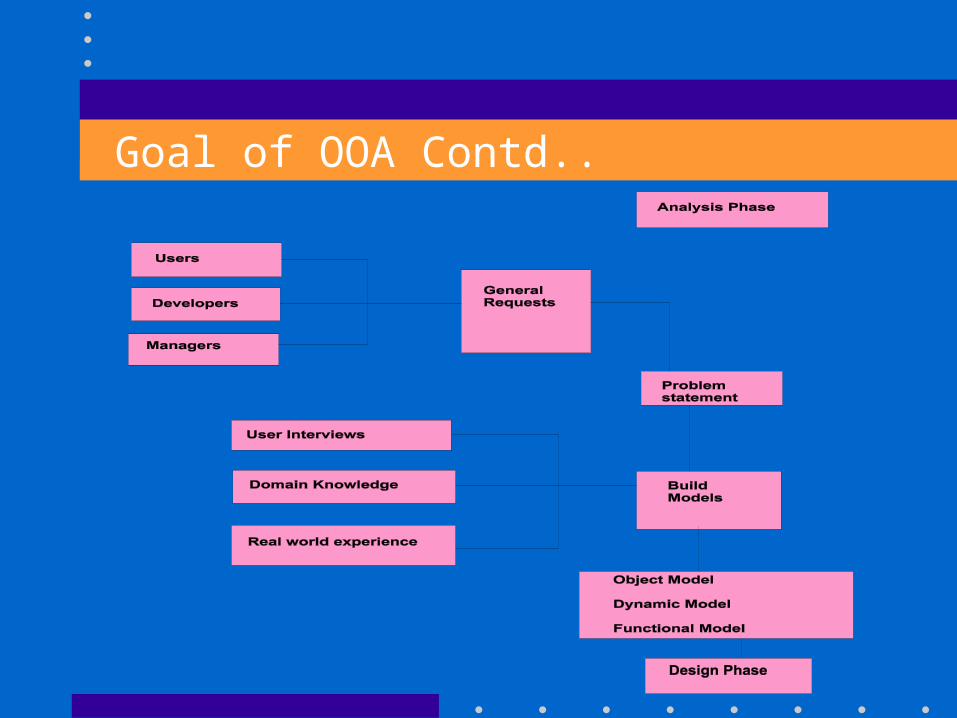
Goal of OOA Contd..
Problem or Requirements Statements•Problem scope
•What is needed
•Application context
•Assumptions
•Performance needs
Problem or Requirements Statements Contd..
The analyst must work with the requestto refine the requirements, so theyrepresent the requestor's true intent. Page 151 include Fig. 8.3 + explanation of paragraph.
Object Modeling
• Object Model shows the static data structure of the real-world system, as object classes and
relationship between classes.
Object Modeling Contd..
•Information for the Object Model comes from
the problem statement
the expert knowledge of the application domain, and
the general knowledge of the real world.
Steps for construction of an Object Model
•Identify all possible Objects and classes
Eliminate Redundant classes
Eliminate irrelevant classes
•Eliminate operations that are applied to objects
•Eliminate Implmentation Constructs.
1. Identify Objects and Classes
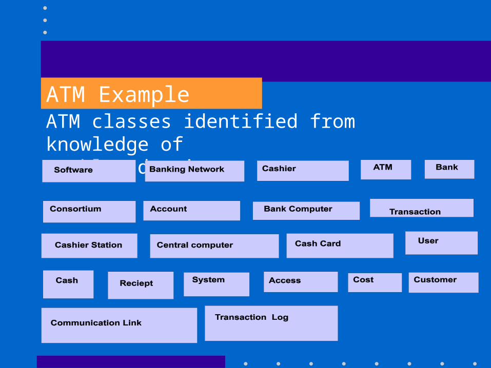
ATM ExampleATM classes identified from knowledge ofproblem domain :
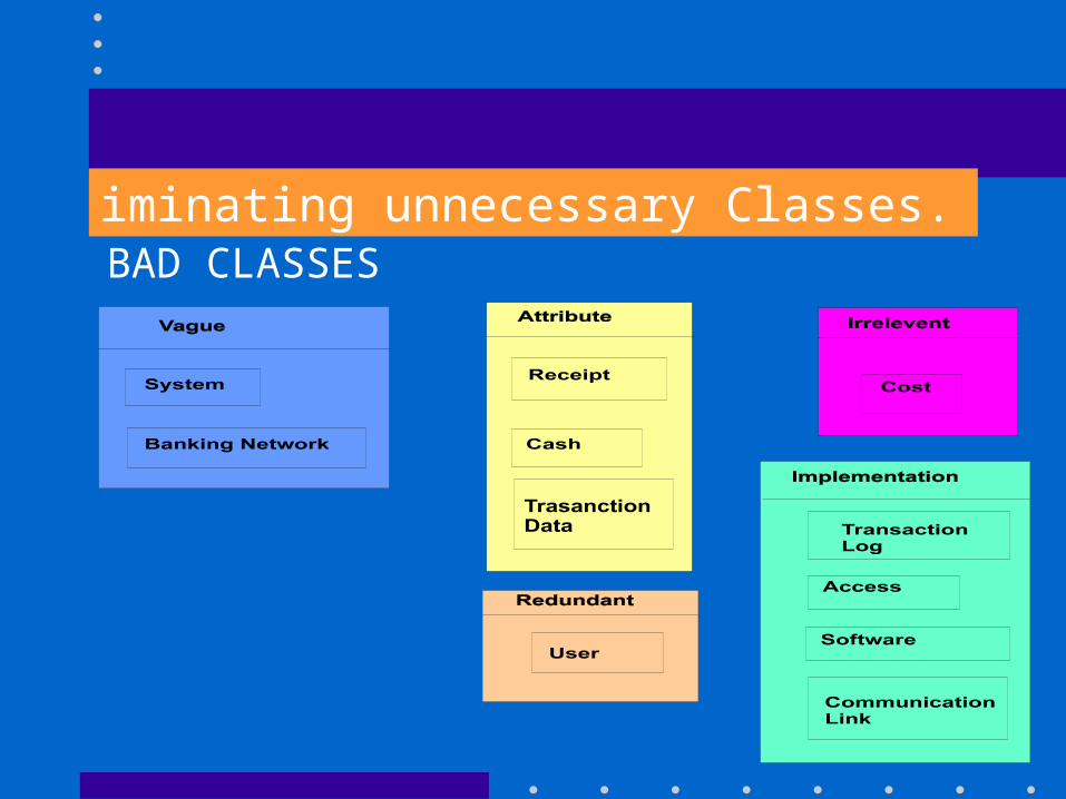
iminating unnecessary Classes.BAD CLASSES
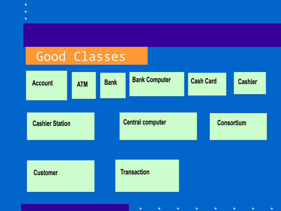
Good Classes
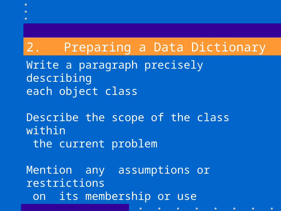
2. Preparing a Data DictionaryWrite a paragraph precisely describing each object class
Describe the scope of the class within the current problem
Mention any assumptions or restrictions on its membership or use
Briefly describe associations, attributesand operations
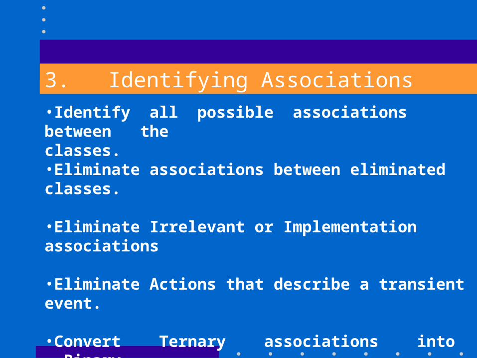
3. Identifying Associations
•Identify all possible associations between the classes. •Eliminate associations between eliminated classes. •Eliminate Irrelevant or Implementation associations •Eliminate Actions that describe a transient event.
•Convert Ternary associations into Binary associations (But without loss of information)
•Eliminate Derived associations.
ATM Example
Some possible Associations from ATM problem Statement
•Banking network includes Cashiers and ATMs•Consortium shares ATMs
•Cashier enters transaction for account
•Bank provides Bank Computer
•Bank owns Cashier station
ATM Example Contd..
•ATMs communicate with Central Computerabout transaction
•Central Computer clear transaction with bank
•ATM accepts Cash Card
•ATM interact with user
•ATM dispenses Cash
ATM Example Contd..
•ATM prints receipts
•System handles concurrent access
•Consortium consists of banks
•Bank holds account
•Consortium owns Central Computer
ATM Example Contd..
•Cost apportioned to banks
•Bank employs Cashier
•Cash Card Accesses account
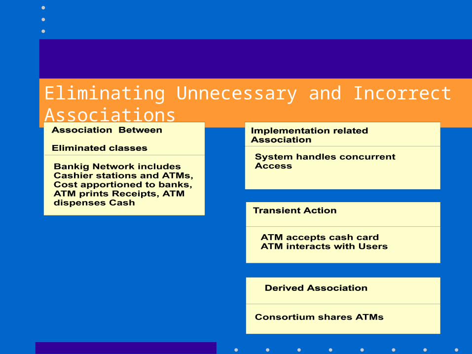
Eliminating Unnecessary and Incorrect Associations
4. Identifying Object Attributes
•should describe the properties of individual objects
•Identify link attributes too.
•Eliminate unnecessary and incorrect attributes.
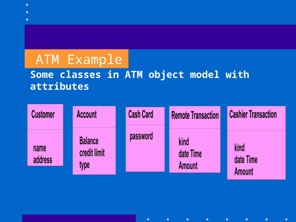
ATM ExampleSome classes in ATM object model with attributes
5. Refining the Classes with Inheritance
•Bottom UP approach
By Generalizing common aspects of existing classes into a superclass.
•Top Down Approach
By defining existing classes into specialized subclasses.
ATM Example
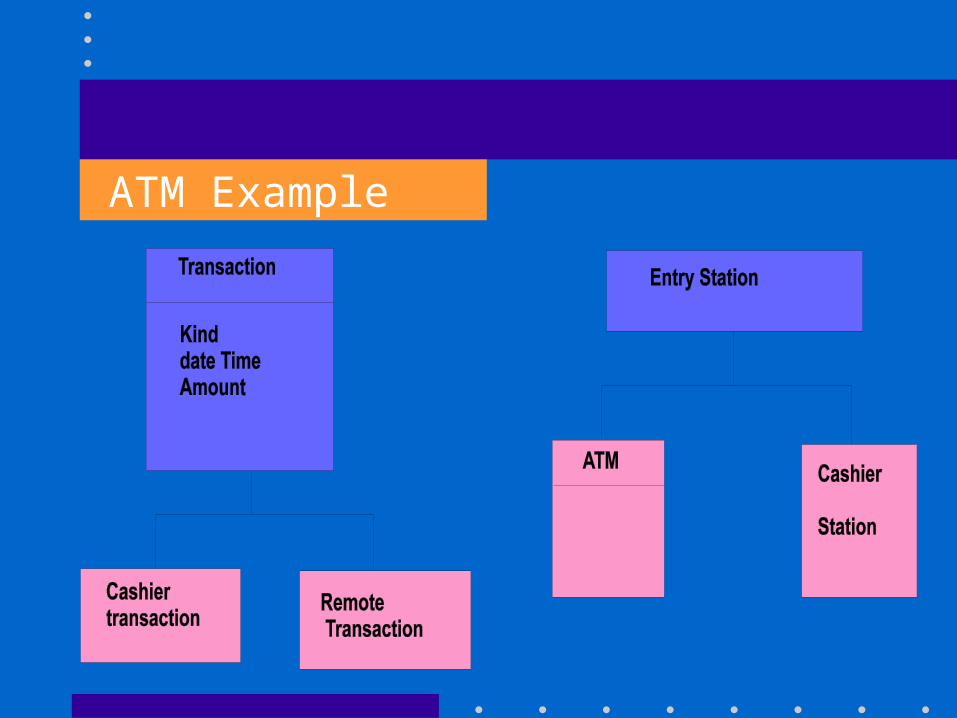
6. Grouping Classes into Modules
•Group classes into sheets and modules
•Tightly coupled classes should be grouped together
•Diagrams may be divided into sheets of uniformsize for convenience in drawing, printing and viewing……...
ATM example for grouping classes intoModules.
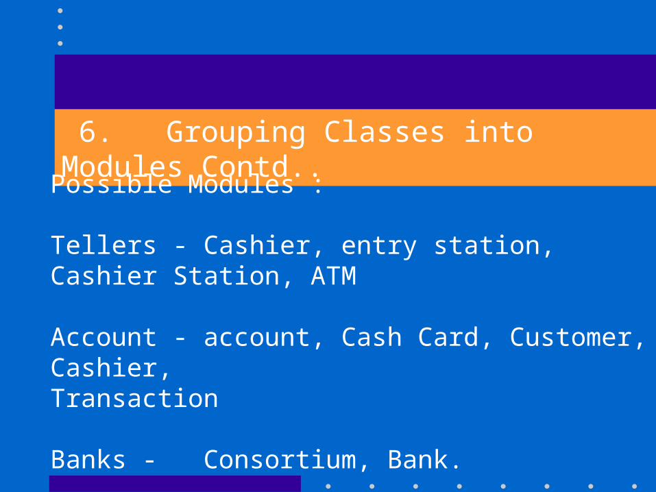
6. Grouping Classes into Modules Contd..
Possible Modules : Tellers - Cashier, entry station, Cashier Station, ATM
Account - account, Cash Card, Customer, Cashier,Transaction
Banks - Consortium, Bank.
Dynamic Modeling
•It shows the time-dependent behaviour of the system and objects
•This model is important for interactive systems only.
•Look for externally visible stimuli and responses.
•Summarize permissible event sequences for each object with a state diagram.
Steps for construction of an Dynamic Model 1. Preparation of a Scenario
•Scenarios show the major interactions, external display formats and information exchanges
•Scenario is a sequence of events
•Event occurs whenever information is exchanged between an object in the system and an outside agent, such as a user, a sensor or another task.
Contd.. ATM Example : Possible Scenario
•The ATM asks the user to insert a Card
•The user inserts a Cash Card.
The ATM accepts the Card and reads serial number
•The ATM requests the password
•The user enters the 'password’•The ATM verifies the serial number and password with the consortium and so on .........
2. Identifying Events betwwn Objects
•Events include all signals, inputs, decisions, interrupts, transitions and action to or from user or external devices.
•Show each scenario as a event-trace or event-flow diagram.
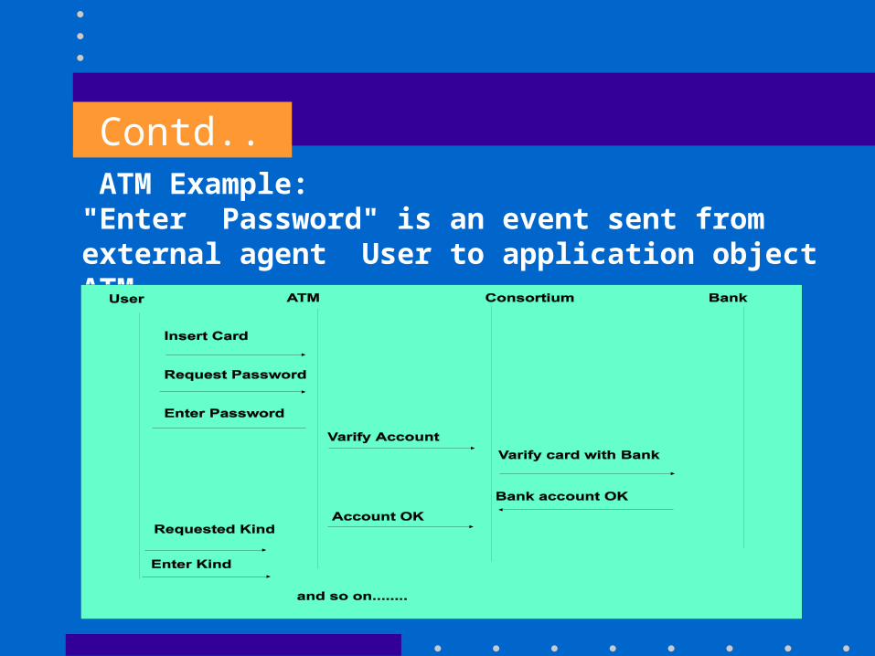
Contd.. ATM Example:"Enter Password" is an event sent from external agent User to application object ATM.
3. Prepare a State Diagram
• for each Object class with retrieval dynamic behaviour
• showing the events the objects receives and sends
• Early scenario or event trace corresponds to a path through the state diagram.
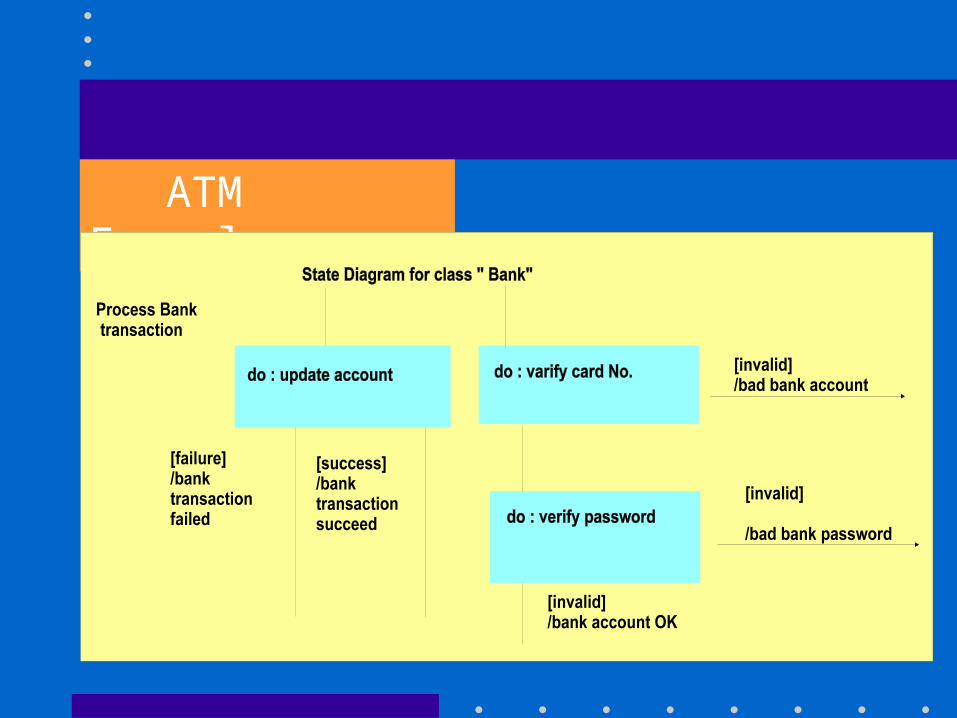
ATM Example :
4. Matching Events between Objects
•Check for completeness and consistency at the system level
•Every event should have a sender and a receiver
4.Matching Events between Objects Contd..
ATM Example:
An "account" can potentially be accessed concurrently by more than one machine.Access to account needs to be controlled to ensure that only one update at a time is applied.
Steps for Construction of Functional Model
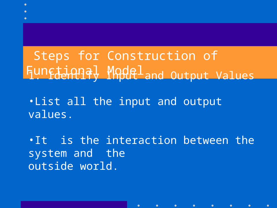
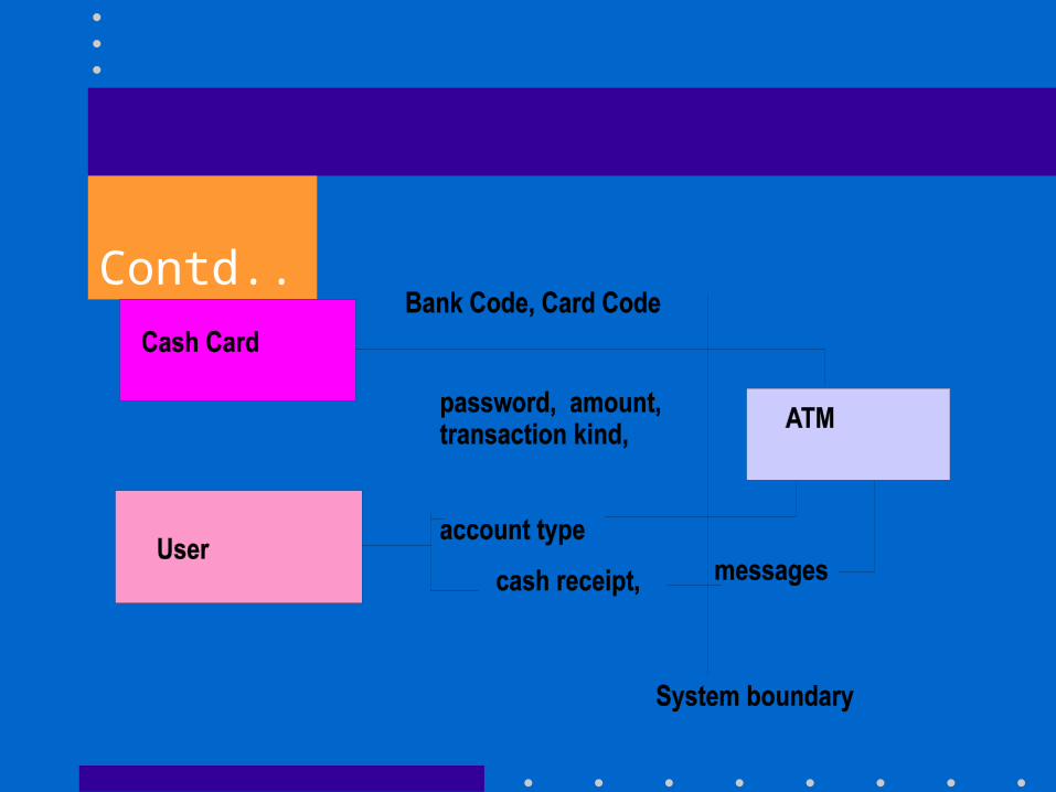
1. Identify Input and Output Values
•List all the input and output values.
•It is the interaction between the system and the outside world.
Contd..
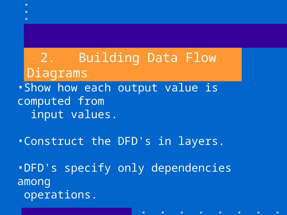
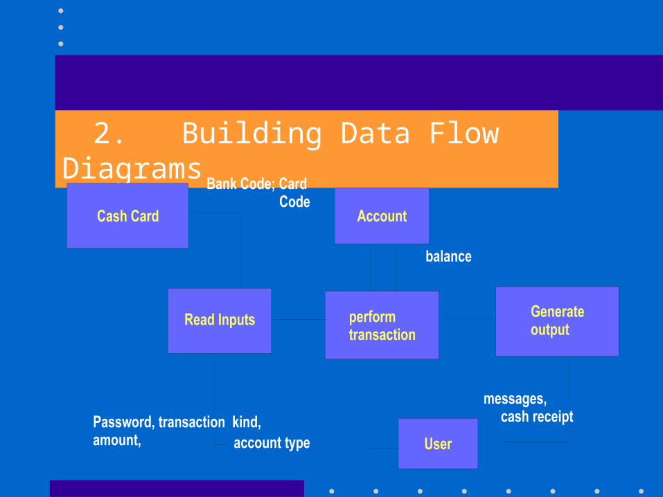
2. Building Data Flow Diagrams
•Show how each output value is computed from input values.
•Construct the DFD's in layers.
•DFD's specify only dependencies among operations.
2. Building Data Flow Diagrams
3. Describng Functions
• Refine the DFD's
• Describe each function
What it does
Not flow to implement it
• Description can be declarative or procedural.
ATM Example
Update-account-function ()
If amount on withdrawal > the current account balance
reject transaction.
If amount on withdrawal < the current account balance
debit the account and dispence the amount request and so on ......…
4. Identify Constraints between Objects
•Constraints are functional dependencies between objects that are not related by an input-output dependency.
•Constraints can be on two objects at the same time.
•or between instances of the same object and different times
4. Identify Constraints between Objects•or between instances of different objects and different hours.
•Constraints are the preconditions on the functions.
ATM Example:
A possible constraint
'No account balance may ever be negative'
5. Specifying Optimization Criteria
Specify values to be maximized, minimized or optimized
In case of conflict, indicate the trade-off.
5. Specifying Optimization CriteriaATM Example:
Possible Optimization Criteria
•Minimize the number of physical messages sent between different sites.
•Minimize the time an account is locked for concurrency reason.
Final Stage :
• Refine the analysis model
• Restate the Requirements if required.
• Verify the analysis model.
• Final verified analysis model serves as the basis for system architecture, design and implementation.
Summary
• Purpose of OOA is to state and understand the problem and application domain, so that a correct design can be constructed
• A good analysis captures the essential features of the problem without introducing implementation artifacts.
SYSTEM DESIGN
During analysis, the focus is on what is to be done, independent of how it is done. During design,
decisions are made about how the problem will be
solved, first at high level, then at increasingly
detailed levels.
SYSTEM DESIGN
System Design is the high level strategy for
solving the problem and building a solution.
The overall organization of a system into
components is called the System Architecture.
SYSTEM DESIGN
The system designee must make the followingdecisions : • Organise the system into sub-systems
• Identify concurrency inherent in the problem
• Allocate sub-system to processor and tasks
• Choose an approach for management of data stores
SYSTEM DESIGN
The system designee must make the followingdecisions : Contd.. •Handle access to global resources
•Choose the implementation of control in software
•Handle boundary conditions
•Set trade off priorities
Contd..
There are a number of architectural styles suitable
for various applications. They differ in placing
emphasis on the three models - Object, Dynamic and
Functional.
Breaking System into sub-systems
The first step in system design is to divide the system into a small number of components called subsystem.
A subsystem is not an object nor a function but a package of classes, associations, operations, events and constraints that are inter-related and that havea reasonably well-defined and small interface with other systems. It defines a coherent way of looking at one aspect of the problem.
Breaking System into sub-systems
To identify the sub-systems in a system, the following should be observed :
• Each subsystem should encompass the aspects of a system that share some common property, like, similar functionality or
same physical location orexecution on the same kind of hardware, etc.
Breaking System into sub-systems• Subsystem can be identified by the services it provide. A service is a group of related functions that share some common purpose.
• Each subsystem should have well-defined interface to the rest of the system.
• Subsystem should be defined so that most interactions are within subsystems, rather than across the subsystem boundaries, in order to reduce the dependencies among the subsystem.
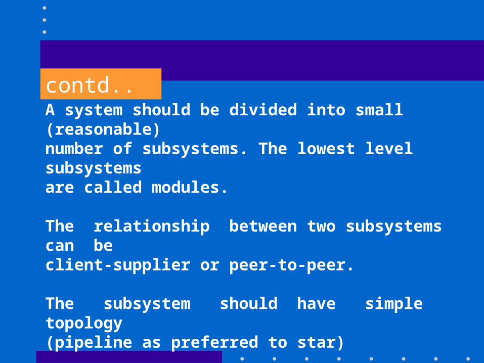
contd..A system should be divided into small (reasonable) number of subsystems. The lowest level subsystems are called modules.
The relationship between two subsystems can be client-supplier or peer-to-peer.
The subsystem should have simple topology (pipeline as preferred to star)
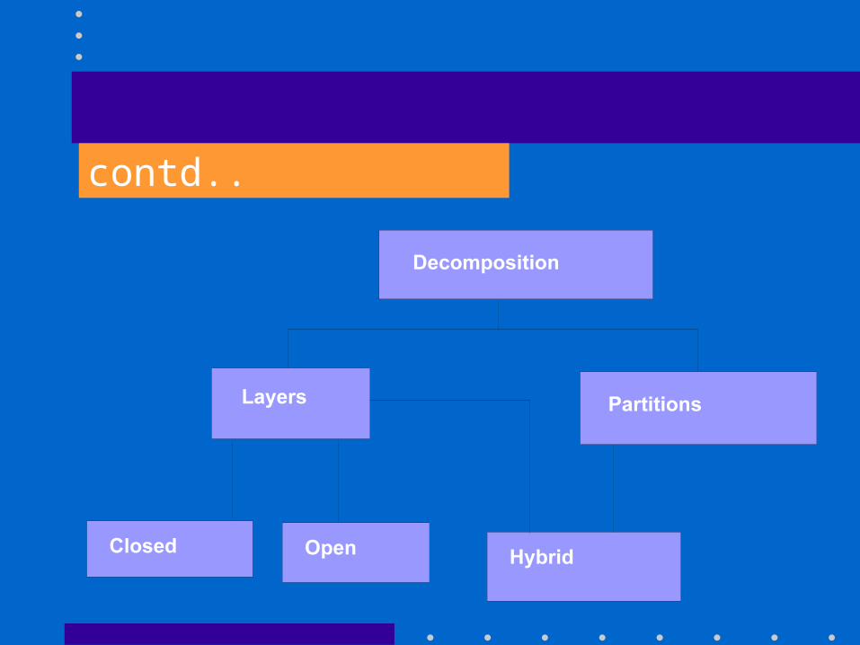
The decomposition of system into subsystem can be organized as a sequence of horizontal layers or vertical partitions.
contd..
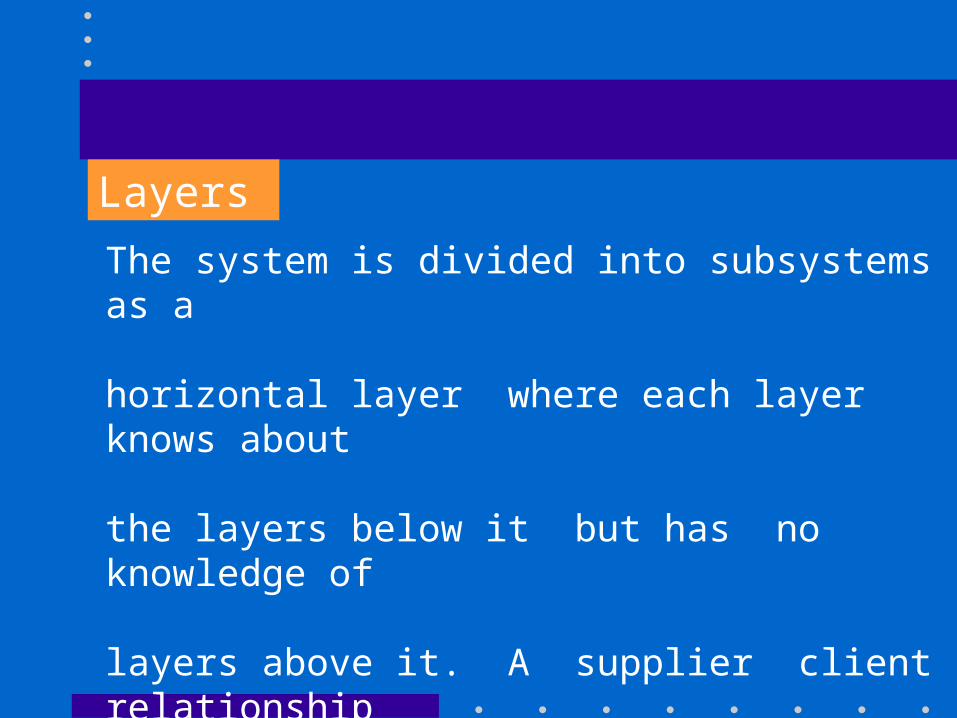
Layers
The system is divided into subsystems as a
horizontal layer where each layer knows about
the layers below it but has no knowledge of
layers above it. A supplier client relationship
exists between lower layers and upper layers.
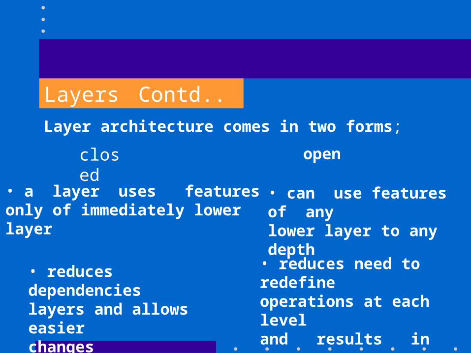
Layers Contd..
closed open
Layer architecture comes in two forms;
• a layer uses features only of immediately lower layer
• reduces dependencies layers and allows easier changes
• can use features of anylower layer to any depth
• reduces need to redefineoperations at each leveland results in moreefficient and compactcode
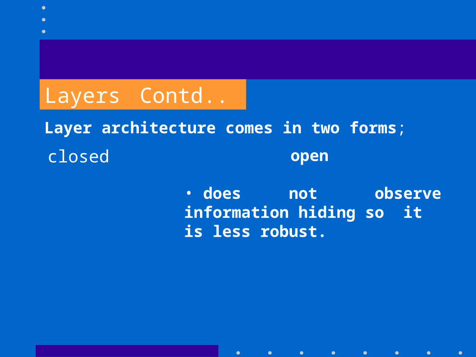
Layers Contd..
closed open
Layer architecture comes in two forms;
• does not observeinformation hiding so itis less robust.
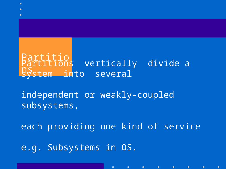
Partitions
Partitions vertically divide a system into several
independent or weakly-coupled subsystems,
each providing one kind of service
e.g. Subsystems in OS.
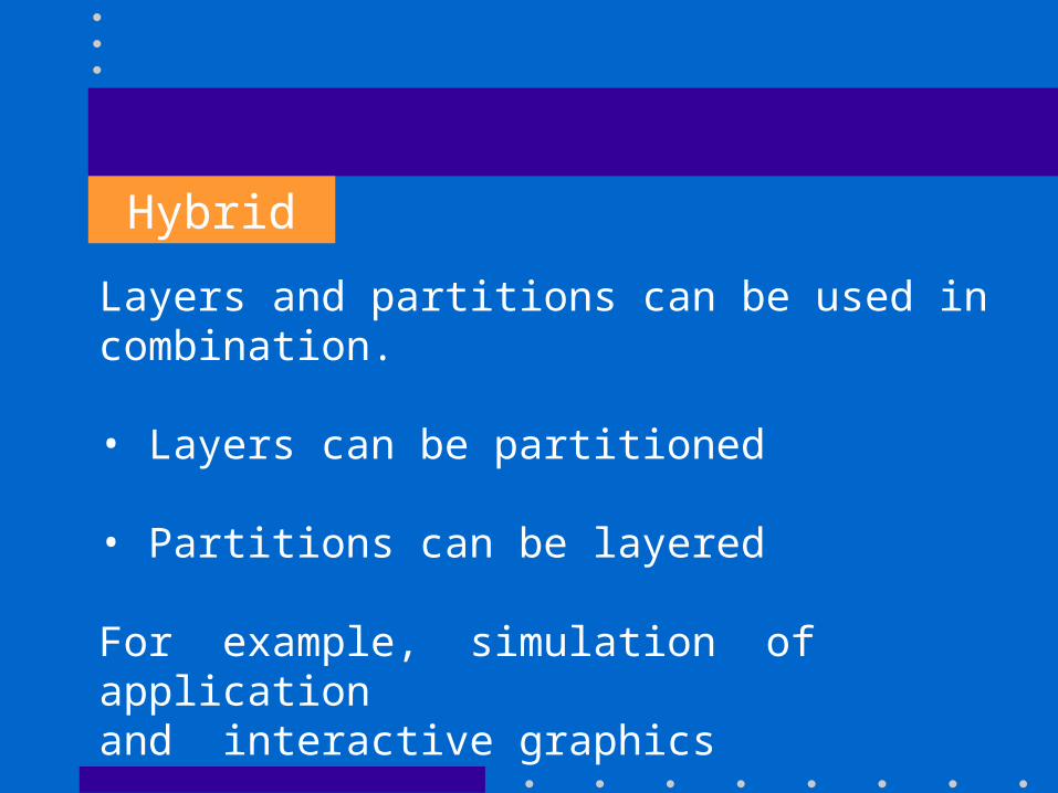
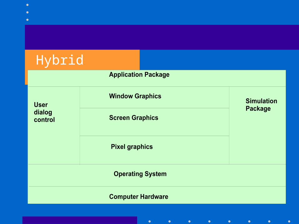
Hybrid
Layers and partitions can be used in combination.
• Layers can be partitioned
• Partitions can be layered
For example, simulation of applicationand interactive graphics
Hybrid Contd..
Identifying Concurrency
System design needs to identify which objects
must be active concurrently and which objects
have activity that in mutually exclusive.
The later objects can be folded together
into a single thread of control or task.
Identifying Concurrency Contd..
There are two ways of identifying concurrency.
1. Identify inherent concurrency
The dynamic model is the guide to identifying concurrency. Two objects are inherently concurrentif they can receive events at the same time withoutinteracting. If the events are unsynchronized, theobjects can not be folded into a single threadof control.
Identifying Concurrency Contd..
2. Defining Concurrent tasks
By examining the state diagrams of individual objects and the exchange of events among them,many objects can be folded together onto a singlethread of control. On each thread of control, only a single object at a time is active. Thread of controlare implemented as tasks in computer systems.