Embed Size (px)
Citation preview

Copyright: Only integral reproduction of this Certificate is permitted without written permission from DNV GL. Electronic copies as PDF or scan of this
Certificate may be available and have the status “for information only”. The sealed and bound version of the Certificate is the only valid version.
Vers
ion:
2
Object Product family of protection relays 1418-18 Type Relion® 670 and 650 series, version 2.2 Serial No. See 2.2
Product(s)
REB670, REC670, RED670, REG670, REL670, RER670, RES670 and RET670 REB650, REC650, RED650, REL650, RET650 and REQ650
Operating range -25 to 70 °C EMC emission class A Mechanical class 1 EMC environment Zone A
Manufacturer ABB AB,
Nätverksgatan 3, Västerås, Sweden *)
ABB India Limited, Plot no. 4A, 5 & 6, Peenya 2nd Phase, Peenya Industrial Estate, Bangalore - 560058. India *)
Client ABB AB,
Nätverksgatan 3, Västerås, Sweden
Tested by DNV GL Netherlands B.V.,
Arnhem, the Netherlands
Date of tests 6 November 2017 to 1 August 2018
The object, constructed in accordance with the description, drawings and photographs incorporated in this Certificate, has been subjected to the series of proving tests in accordance with the complete type test requirements of
IEC 60255-1:2009
The results are shown in the record of proving tests and the oscillograms attached hereto. The values obtained and the general performance are considered to comply with the above standard(s) and to
justify the ratings assigned by the manufacturer as listed on pages 5 and 6.
This Certificate applies only to the object tested. The responsibility for
conformity of any object having the same type references as that tested rests with the Manufacturer. *) as declared by the manufacturer This Certificate consists of 22 pages in total.
DNV GL Netherlands B.V.
J.P. Fonteijne Executive Vice President KEMA Laboratories
Arnhem, 4 October 2018
-2- 1418-18
Vers
ion:
1
INFORMATION SHEET 1 KEMA Type Test Certificate A KEMA Type Test Certificate contains a record of a series of (type) tests carried out in accordance with a recognized standard. The object tested has fulfilled the requirements of this standard and the relevant ratings assigned by the manufacturer are endorsed by DNV GL. In addition, the object’s technical drawings have been verified and the condition of the object after the tests is assessed and
recorded. The Certificate contains the essential drawings and a description of the object tested. A KEMA Type Test Certificate signifies that the object meets all the requirements of the named subclauses of the standard. It can be identified by gold-embossed lettering on the cover and a gold seal on its front sheet. The Certificate is applicable to the object tested only. DNV GL is responsible for the validity and the contents of the Certificate. The responsibility for conformity of any object having the same type
references as the one tested rests with the manufacturer.
Detailed rules on types of certification are given in DNV GL’s Certification procedure applicable to KEMA Laboratories. 2 KEMA Report of Performance A KEMA Report of Performance is issued when an object has successfully completed and passed a subset (but not all) of test programmes in accordance with a recognized standard. In addition, the
object’s technical drawings have been verified and the condition of the object after the tests is assessed and recorded. The report is applicable to the object tested only. A KEMA Report of Performance signifies that the object meets the requirements of the named subclauses of the standard. It can be identified by silver-embossed lettering on the cover and a silver seal on its front sheet. The sentence on the front sheet of a KEMA Report of Performance will state that the tests have been carried out in accordance with …… The object has complied with the relevant requirements.
3 KEMA Test Report A KEMA Test Report is issued in all other cases. Reasons for issuing a KEMA Test Report could be:
• Tests were performed according to the client’s instructions. • Tests were performed only partially according to the standard. • No technical drawings were submitted for verification and/or no assessment of the condition of
the object after the tests was performed. • The object failed one or more of the performed tests. The KEMA Test Report can be identified by the grey-embossed lettering on the cover and grey seal on its front sheet. In case the number of tests, the test procedure and the test parameters are based on a recognized standard and related to the ratings assigned by the manufacturer, the following sentence will appear on the front sheet. The tests have been carried out in accordance with the client's instructions. Test
procedure and test parameters were based on ..... If the object does not pass the tests such behaviour will be mentioned on the front sheet. Verification of the drawings (if submitted) and assessment of the condition after the tests is only done on client's request. When the tests, test procedure and/or test parameters are not in accordance with a recognized standard, the front sheet will state the tests have been carried out in accordance with client’s
instructions.
4 Official and uncontrolled test documents The official test documents of DNV GL are issued in bound form. Uncontrolled copies may be provided as a digital file for convenience of reproduction by the client. The copyright has to be respected at all times.

-3- 1418-18
Vers
ion:
2
TABLE OF CONTENTS
1 Summary ................................................................................................................... 4
2 Identification of the object tested .................................................................................. 5
2.1 Ratings/characteristics of the object tested 5
2.2 Description of the object tested 7
2.3 List of drawings 8
2.4 Photograph of test objects 9
3 General information ................................................................................................... 10
3.1 The tests were witnessed by 10
3.2 The tests were carried out by 10
3.3 Reference to other reports 10
3.4 Subcontracting 10
3.5 Measurement uncertainty 10
3.6 Instruments used 10
4 Test arrangement ...................................................................................................... 11
5 Risk assessment ....................................................................................................... 12
6 Communication protocols ........................................................................................... 14
7 Photographs of printboards......................................................................................... 15
8 Measurement uncertainty ........................................................................................... 22

-4- 1418-18
Vers
ion:
2
1 SUMMARY
By order of the client type tests according to IEC 60255-1 have been performed on the product family
of protection relays, Relion 670 and 650 series, version 2.2.
Test / Measurement Test result
Dimensions of structure and visual inspection Passed
Functional requirements Passed
Product safety Passed
Electromagnetic compatibility (EMC) Passed
Burden tests Passed
Climatic environmental conditions Passed
Mechanical environmental conditions Passed
Enclosure protection Passed
Contact performance Passed
A risk assessment has been performed for the complete Relion 670 and 650 series, version 2.2. The
risk assessment shows what test on which IED need to be conducted to cover compliance to the
requirements for the whole product family as stated on page 1 of this certificate.
Therefore, type tests were done on various test objects of various IED types, all belonging to the
Relion 670 and 650 series, version 2.2. The required tests and the corresponding results of these type
tests are described in the following documents/reports:
Report number Relion version 2.2 device
1417-18 REC670
1414-18 RED670
1410-18 REL670
1416-18 REQ650
1412-18 RER670
1408-18 RES670
1415-18 RET670
1446-18 Tests of protection functions

-5- 1418-18
Vers
ion:
2
2 IDENTIFICATION OF THE OBJECT TESTED
2.1 Ratings/characteristics of the object tested
Rated voltage, UR 110-220 Vac
Rated current IR 1/5 A
Rated frequency 16,7/50/60 Hz
Rated auxiliary voltage 24-60 Vdc
90-250 Vdc
Binary input voltage 24- 250 Vdc
Output contact continuous current (BOM) 8 A
Output contact continuous current (SOM) 5 A
Maximum operating temperature 70 °C
Minimum operating temperature -25 °C
Maximum storage temperature 85 °C
Minimum storage temperature -40 °C
Classification
IP-class, front side (with sealing strip)
IP-class, front side (without sealing strip)
IP-class sides
IP-class rear side (compression terminal)
IP-class ring lug terminal
IP 54
IP 40
IP 40
IP 20
IP 10
Mechanical class 1
EMC emission class A
EMC immunity zone A
Overvoltage category II & III
Pollution degree 2

-6- 1418-18
Vers
ion:
2
Protection functions tested
ANSI code Function code
Distance protection 21 ZMFPDIS 1),
ZMFCPDIS, ZRWPDIS
Phase undervoltage protection 27 UV2PTUV
Negative sequence overcurrent or current unbalance
protection
46 NS2PTOC
Thermal protection 26, 49 LPTTR, TRPTTR
Instantaneous phase overcurrent protection 50 PHPIOC
Time delayed phase overcurrent protection 51 OC4PTOC
Instantaneous residual overcurrent protection 50N EFPIOC
Time delayed residual overcurrent protection 51N EF4PTOC
Voltage restrained overcurrent protection 51V VRPVOC
Phase overvoltage protection 59 OV2PTOV
Residual overvoltage protection 59N ROV2PTOV
Directional phase overcurrent protection 67 OC4PTOC
Directional residual overcurrent protection 67N EF4PTOC, SDEPSDE
Line differential protection 87L L3CPDIF, L4CPDIF
Transformer differential protection 87T T2WPDIF 2), T3WPDIF
1) Manufacturer declares that ZMFPDIS and ZMFCPDIS are fundamentally the same functions.
2) Manufacturer declares that T2WPDIF and T3WPDIF are fundamentally the same functions.

-7- 1418-18
Vers
ion:
2
2.2 Description of the object tested
Manufacturer ABB AB,
Nätverksgatan 3, Västerås, Sweden
ABB India Limited,
Plot no. 4A, 5 & 6, Peenya 2nd Phase, Peenya Industrial
Estate, Bangalore - 560058. India
Type Relion 670 and 650 series, version 2.2
Object Product family of protection relays
Settings Unless otherwise specified, the default settings of the
manufacturer were used.
The table underneath gives an overview of the test objects. More detailed information concerning the
individual test objects is present in the respective Reports of performance.
Type Serial no. Firmware version Manufacturing Location
IED no.
REC670 I1741048 2.2.1.10 India 1A
T1752171 2.2.2.3 Sweden 1B
RET670 T1738217 2.2.1.10 Sweden 2A
T1738218 2.2.1.10 Sweden 2B
I1817001 2.2.2.3 India 2C
RED670 T1819167 2.2.2.3 Sweden 3A (II)
T1738216 2.2.1.10 Sweden 3B
T1739128 2.2.1.10 Sweden 3C
T1739129 2.2.1.10 Sweden 3D
REL670 I1741047 2.2.1.10 India 4
RES670 T1738219 2.2.1.10 Sweden 5
T1819165 2.2.2.3 Sweden 5B
REQ650 T1738222 2.2.1.10 Sweden 6
RER670 T1738220 2.2.1.10 Sweden 7A
T1738221 2.2.1.10 Sweden 7B

-8- 1418-18
Vers
ion:
2
2.3 List of drawings
The client has submitted files containing drawings and documents of the IEDs and their modules.
These files are kept in the KEMA Laboratories project file.
KEMA Laboratories has made use of these drawings / documents during the execution of the tests.
KEMA Laboratories has not verified in detail that these drawings and documents represent the object
tested.

-9- 1418-18
Vers
ion:
2
2.4 Photograph of test objects
Photographs of the objects tested are presented in the respective reports of performance.

-10- 1418-18
Vers
ion:
2
3 GENERAL INFORMATION
3.1 The tests were witnessed by
The tests were carried out without a representative of the client present.
3.2 The tests were carried out by
Name Company
Martijn Dallinga
Herman Koerts
Mihai Bivolaru
DNV GL Netherlands B.V.,
Arnhem, the Netherlands
3.3 Reference to other reports
Report no. Tests described
10021419-OPE/INC 162464 Communication requirements in accordance with
IEC 61850 Edition 2 Parts 6, 7-1, 7-2, 7-3, 7-4 and 8-1
10021419-OPE/INC 16-2490 Communication requirements in accordance with
IEC 60870-5-103
1029-16 Type test certificate 670 v2.0
3.4 Subcontracting
The following tests were subcontracted to DEKRA Certification B.V., Arnhem, the Netherlands:
• measurement of radiated emission in accordance with IEC 60255-26 and CISPR22
• measurement of conducted emission in accordance with IEC 60255-26 and CISPR22
• radiated, radio-frequency and electromagnetic field immunity test in accordance with
IEC 60255-26 and IEC 61000-4-3
• contact performance tests in accordance with IEC 61810-1.
The following tests were subcontracted to Sebert Trillingstechniek, Bergschenhoek, the Netherlands:
• vibration response and endurance in accordance with IEC 60255-21-1
• shock response and withstand in accordance with IEC 60255-21-2
• bump test in accordance with IEC 60255-21-2
• seismic test in accordance with IEC 60255-21-3.
3.5 Measurement uncertainty
A table with measurement uncertainties is enclosed in this Certificate. Unless otherwise stated, the
measurement uncertainties of the results presented in this Certificate are as indicated in that table.
3.6 Instruments used
A detailed list with instruments used is enclosed in the respective Reports of performance.

-11- 1418-18
Vers
ion:
2
4 TEST ARRANGEMENT
A general test set-up is made by connecting the protective relay to a relay test set. The protective
relay is powered with rated auxiliary voltage. Currents and/or voltages are applied to the analogue
input module(s). If required status signals are applied to the binary input module(s). The operation
and resetting is monitored with the binary output modules operated with 24 VDC. The protective relay
is parameterized and monitored by means of the human machine interface and interface on the
display and LED's. Settings of the IED under test and information from the IED is handled by PCM600
software from ABB. Communication between IED and parameterizing and monitoring device is via
Ethernet communication.
Protective relay
Analog
input
Binary
I/O
Current/voltage
amplifier
Relay test set
Analog
output
Binary
I/O
Parameterizing and
monitoring device
Monitoring device

-12- 1418-18
Vers
ion:
2
5 RISK ASSESSMENT
Clause 7.3 in IEC 60255-1 describes that testing a product which is part of a product family shall be
considered sufficient to cover the entire product family provided a documented risk assessment is
carried out to determine which type tests are valid and which tests need to be repeated on the rest of
the product family.
A detailed risk assessment for Relion 670 and 650 series, version 2.2 is enclosed in the Excel
document with file name 72126077 ABB_650_670 V2.2_risk_assessment dated 29 August 2018.
The risk assessment revealed that not all product variants of the Relion 670 and 650 series,
version 2.2 was required to be tested to still certify all product variants of the family and as stated on
page 1 of this certificate.
The table below gives an condensed overview of which test was done on what IED type.
No. Test description Standard IED 650/670 type tested
1 Dimensions of structure and visual inspection
1.1 Markings IEC 60255-27 REC, RED, REL, REQ, RER, RES, RET
1.2 Documentation IEC 60255-27 REC, RED, REL,
1.3 Packaging IEC 60255-27 REC, RED, REL
1.4 Dimensions IEC 60297-3-101 REC, RED, REL
2 Functional requirements
2.1 Differential protection IEC 60255-13 RED, RET
2.2 Distance protection IEC 60255-121 RED, RER
2.3 Over/under voltage protection IEC 60255-127 RED
2.4 Thermal protection IEC 60255-149 RER, RET
2.5 Over/under current protection IEC 60255-151 RED, RET
3 Product safety requirements
3.1 Clearance and creepage distances IEC 60255-27 REC, REL
3.2 Accessible parts test IEC 60255-27 REC, REL, REQ
3.3 IP rating IEC 60255-27 REC, RED, RES
3.4 Impulse voltage IEC 60255-27 REL, REQ, RES, RET, note 1
3.5 AC or DC dielectric voltage IEC 60255-27 REL, REQ, RES, RET, note 1
3.6 Insulation resistance IEC 60255-27 REL1, REQ, RES,
RET
3.7 Protective bonding resistance IEC 60255-27 REQ, RES, RET
3.8 Flammability of insulating materials, components and
fire enclosures IEC 60255-27 REC, RET
3.9 Single-fault condition IEC 60255-27 REC, RET
3.10 Thermal short time CT and VT inputs IEC 60255-27 RER, Note 2
4 EMC requirements
4.1 Conducted emission IEC 60255-26
CISPR 22
REQ, RER, RES
4.2 Radiated emission IEC 60255-26
CISPR 11
CISPR 22
REQ, RER, RES
4.3 Radiated radiofrequency electromagnetic field IEC 60255-26
IEC 61000-4-3
IEEE C37.90.2
REL, RER, RES

-13- 1418-18
Vers
ion:
2
No. Test description Standard IED 650/670 type
tested
4.4 Electrostatic discharge IEC 60255-26
IEC 61000-4-2
IEEE C37.90.3
REL, RER, RES
4.5 Power frequency magnetic field IEC 60255-26
IEC 61000-4-8
REL, RER, RES
4.6 Conducted disturbance induced by radio-frequency fields
IEC 60255-26
IEC 61000-4-6
REL, RER, RES
4.7 Fast transients IEC 60255-26
IEC 61000-4-4
REL, RER, RES
4.8 Slow damped oscillatory wave IEC 60255-26
IEC 61000-4-18
IEEE C37.90.1
REL, RES
4.9 Surge IEC 60255-26
IEC 61000-4-5
REL, RER, RES
4.10 AC and DC voltage dips and interruptions IEC 60255-26
IEC 61000-4-11
IEC 61000-4-29
REL, RES
4.11 AC component in DC power supply (ripple) IEC 60255-26
IEC 61000-4-17
REL, RES
4.12 Gradual shut-down/start-up for DC power supply IEC 60255-26 REL, RES
4.13 Reversal of DC power supply voltage IEC 60255-27 REL, RES
4.14 Power frequency voltage IEC 60255-26
IEC 61000-4-16
REL, RES
5 Energizing quantities
5.1 Burden VT and CT inputs IEC 60255-1 RER, note 2
5.2 Burden, inrush current DC power supply IEC 60255-1 REL, RES
5.3 Burden binary input IEC 60255-1 Note 2
5.4 Input circuit for energizing quantities IEC 60255-1 RER, note 2
6 Contact performance
6.1 Mechanical endurance IEC 60255-1 Note 2
6.2 Limiting making capacity IEC 60255-1 Note 2
6.3 Continuous contact current IEC 60255-1 Note 2
6.4 Short time contact current IEC 60255-1 Note 2
6.5 Limited breaking capacity IEC 60255-1 Note 2
7 Climatic environmental requirements
7.1 Cold test storage & operational IEC 60068-2-2 REQ, RES, RET
7.2 Dry heat test storage & operational IEC 60068-2-1 REQ, RES, RET
7.3 Change of temperature test IEC 60068-2-14 REQ, RES, RET
7.4 Damp heat steady-state test IEC 60068-2-78 REQ, RES, RET
7.5 Cyclic temperature with humidity test IEC 60068-2-30 REQ, RES, RET
8 Mechanical requirements
8.1 Vibration test response & endurance IEC 60255-21-1 REC, RED, RES
8.2 Shock test response & withstand IEC 60255-21-2 REC, RED, RES
8.3 Bump test IEC 60255-21-2 REC, RED, RES
8.4 Seismic test IEC 60255-21-3 REC, RED, RES
9 Enclosure protection IEC 60255-27
IEC 60529
REC, RED, RES
Note
1: Only on RJ45 SFP port.
2: Test results of 670-series v 2.0 are re-used.

-14- 1418-18
Vers
ion:
2
6 COMMUNICATION PROTOCOLS
The communication protocols and the type of communication media, used for communication
with the equipment, shall be stated by the manufacturer. Protocols preferred are those with an
IEC standard. Conformance testing shall be performed to ensure that they comply with the
relevant standard or specification. See IEC 60255-1 subclause 6.6.
The results of communication protocol testing have been enclosed in the reports;
Report no. Tests described
10021419-OPE/INC 162464 Communication requirements in accordance with
IEC 61850 Edition 2 Parts 6, 7-1, 7-2, 7-3, 7-4 and 8-1
10021419-OPE/INC 16-2490 Communication requirements in accordance with
IEC 60870-5-103

-15- 1418-18
Vers
ion:
2
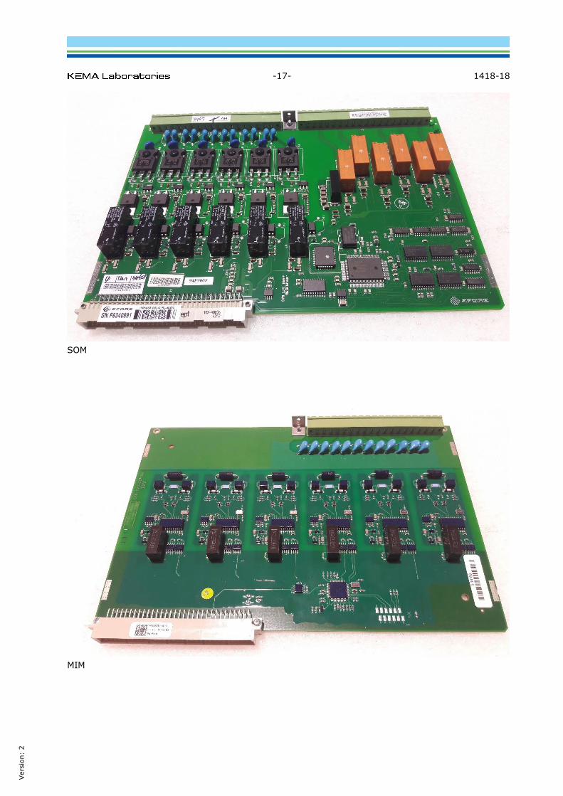
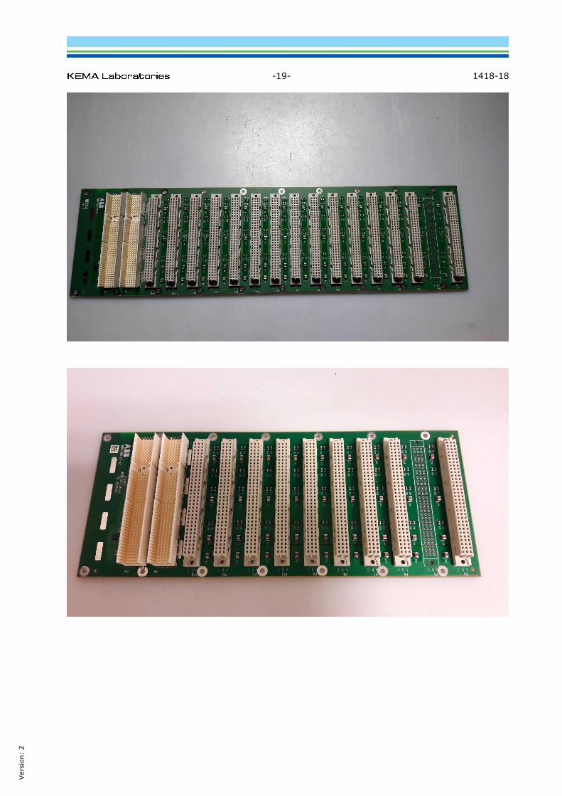
7 PHOTOGRAPHS OF PRINTBOARDS
PSM
BIM

-16- 1418-18
Vers
ion:
2
BOM
IOM
-17- 1418-18
Vers
ion:
2
SOM
MIM

-18- 1418-18
Vers
ion:
2
TRM
At the top ADM board with GTM, IRIG-B and SLM. NUM at the bottom.
-19- 1418-18
Vers
ion:
2

-20- 1418-18
Vers
ion:
2
CBM
UBM

-21- 1418-18
Vers
ion:
2
UBM
LHMI
-22- 1418-18
Vers
ion:
2
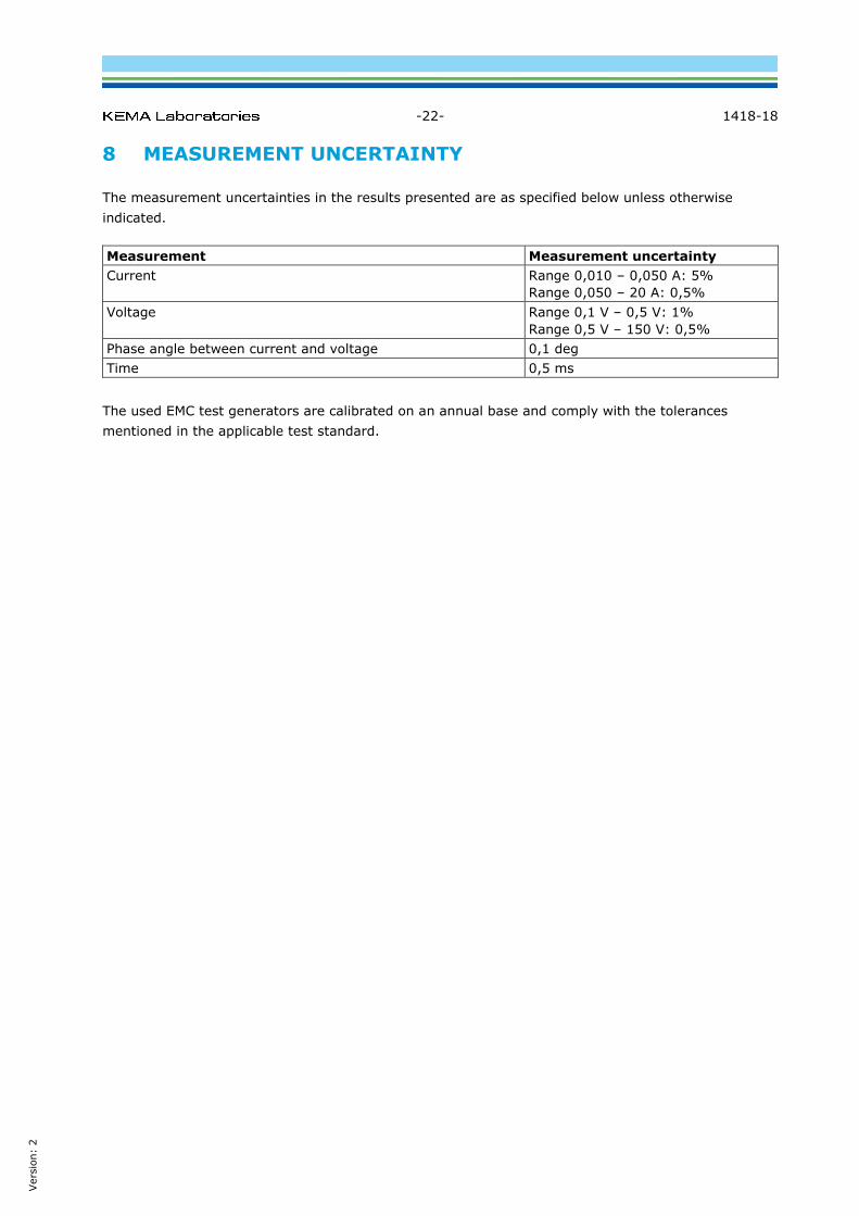
8 MEASUREMENT UNCERTAINTY
The measurement uncertainties in the results presented are as specified below unless otherwise
indicated.
Measurement Measurement uncertainty
Current Range 0,010 – 0,050 A: 5%
Range 0,050 – 20 A: 0,5%
Voltage Range 0,1 V – 0,5 V: 1%
Range 0,5 V – 150 V: 0,5%
Phase angle between current and voltage 0,1 deg
Time 0,5 ms
The used EMC test generators are calibrated on an annual base and comply with the tolerances
mentioned in the applicable test standard.


![Describing an Object’s Position - Scholastic...to other positions or stationary objects [GCO 1/3] • 35.0 place an object in an identified position relative to another object or](https://img.pdfslide.us/doc/110x75/5ecc1ee1283e5866285333df/describing-an-objectas-position-to-other-positions-or-stationary-objects.jpg)