Embed Size (px)
Citation preview
*
t
i
REEIVEB 8Y TIC NOV 2 6 1984
NUREG/CR-3853ORNL-6093
OAK RIDGENATIONALLABORATORY
MM* Ft TIN MM* FtlETTF*
Preloading of Bolted Connections in Nuclear Reactor
Component Supports
G. T. Yahr
Prepared for the U.S. Nuclear Regulatory Commission Office of Nuclear Regulatory Research
Under Interagency Agreement DOE 40-550-75
OPERATED BYMARTIN MARIETTA ENERGY SYSTEMS, INC. FOR THE UNITED STATES DEPARTMENT OF ENERGY jisiit itiiioi r? thtcs meifisif is iferoa
Printed in the United States of America. Available from National Technical Information Service
U.S. Department of Commerce 5285 Port Royal Road, Springfield, Virginia 22161
Available from
GPO Sales ProgramDivision of Technical Information and Document Control
U.S. Nuclear Regulatory Commission Washington, D.C. 20555
This report was prepared as an account of work sponsored by an agency of the United States Government. Neither the U nited States Government nor any agency thereof, nor any of their employees, makes any warranty, express or implied, or assumes any legal liability or responsibility for the accuracy, completeness, or usefulness of any information, apparatus, product, or process disclosed, or represents that its use would not infringe privately owned rights. Reference herein to any specific commercial product, process, or service by trade name, trademark, manufacturer, or otherwise, does not necessarily constitute or imply its endorsement, recommendation, or favoring by the United States Government or any agency thereof. The views and opinions of authors expressed herein do not necessarily state or reflect those of the United States Government or any agency thereof.

DISCLAIMER
This report was prepared as an account of work sponsored by an agency of the United States Government. Neither the United States Government nor any agency thereof, nor any of their employees, makes any warranty, express or implied, or assumes any legal liability or responsibility for the accuracy, completeness, or usefulness of any information, apparatus, product, or process disclosed, or represents that its use would not infringe privately owned rights. Reference herein to any specific commercial product, process, or service by trade name, trademark, manufacturer, or otherwise does not necessarily constitute or imply its endorsement, recommendation, or favoring by the United States Government or any agency thereof. The views and opinions of authors expressed herein do not necessarily state or reflect those of the United States Government or any agency thereof.
DISCLAIM ER
Portions of this document may be illegible in electronic image
products. Images are produced from the best available
original document.
f-h O fl rf ET (D
00 0J
e 3 o- (D H
O KlW
O M S
O rf
f-t)
CD
CS cn 9 2!
c O
PL
o n
j1
0QI'S
/ft
M 1
-f /TvC3
^
® 2
lX3 * n> rt
i—3
IWZ
'O!> S
3i—3 r
tM
fy ■
1 «
g 2
* 3
5
2 ro
fir»
i jS3
a>
rf 3
fD
3
r"3 r
lw m
o o
* as
8*
^
^ OQ
fD > D
O ^
O. (D
03e
2 E, o
h^
ro fD
03 O -P-i S
'3
s-W f
DO
3S
U252
S!i
4?-
O I Ui Ul
0 1 'vl Ul
% m n> m 3 o 13*
O 02 r+ fD
K 02 3 3 03 o 3 H*
hd
C O'
M -
O
H*
rt
03 cr o
fD
O
I t*
o o rf O o* fl>
rM
OQ00 C
O -F
> rt N2 4> 00
O 9 H 02 3* 1-!CO c3 V O Pd H CO
s § O £ £
DIS
CL
AIM
ER
Thi
s re
port w
as p
repa
red
as a
n ac
coun
t o
f w
ork
spon
sore
d by
an
agen
cy o
f the
Uni
ted
Sta
tes
Gov
ernm
ent.
Nei
ther
the
Uni
ted
Sta
tes
Gov
ernm
ent
nor
any
agen
cy t
here
of,
nor
any
of t
heir
empl
oyee
s, m
akes
any
war
rant
y, e
xpre
ss o
r im
plie
d, o
r as
sum
es a
ny l
egal l
iabili
ty o
r re
spon
si
bili
ty f
or t
he a
ccur
acy, c
ompl
eten
ess, o
r us
eful
ness
of
any
info
rmat
ion, a
ppar
atus
, pr
oduc
t, or
pr
oces
s di
sclo
sed, o
r re
pres
ents t
hat
its u
se w
ould n
ot i
nfrin
ge p
rivat
ely
owne
d rig
hts. R
efer
en
ce h
erei
n to
any
spe
cific
com
mer
cial p
rodu
ct,
proc
ess, o
r se
rvic
e by
tra
de n
ame, t
rade
mar
k,
man
ufac
ture
r, o
r ot
herw
ise
does n
ot n
eces
saril
y co
nstit
ute
or i
mpl
y its
end
orse
men
t, re
com
m
enda
tion, o
r fa
vorin
g by
the
Uni
ted
Sta
tes
Gov
ernm
ent
or a
ny a
genc
y th
ereo
f. T
he v
iew
s an
d op
inio
ns o
f au
thor
s ex
pres
sed
here
in
do n
ot
nece
ssar
ily
stat
e or r
efle
ct t
hose o
f th
e U
nite
d S
tate
s G
over
nmen
t or
any
agen
cy t
here
of.
H 3 00 H- 3 CD fD fj H- do H fD O 3* 3 O M O 2^ u H-< H* 03 H* O 3
■ I—i co ' Ln O o tsj w Ut
ROUGEPORTIONS OF THIS REPORT ARE ILLEGIBLE.
It has been reproduced from the best available copy to permit the broadest possible availability.

CONTENTS
Page
ABSTRACT ................. ................................. ....... 11. INTRODUCTION ..... .............................. ............ 12. BACKGROUND .................................................. 33. STRESS CORROSION CRACKING .................... .............. 54. PRELOAD RANGE SELECTION ............. ...................... 9
4.1 Principles of Bolted Joints ..... ........... .......... 94.1.1 Tension joints ....... ................ ......... 94.1.2 Shear loading ........... ................... . 154.1.3 Eccentric shear ..... ........................... 174.1.4 Combined tension and shear .................. . 17
4.2 Joint Stiffness ..................... .................. 184.3 Relaxation Effects ..................................... 214.4 Selection of Preload ...... .................. ......... 24
5. APPLICATION AND MEASUREMENT OF PRELOAD ...................... 305.1 Mechanics of Bolt Preloading ............ .......... . 305.2 Quantities Measured to Assess Preload ................. 335.3 Accuracy of the Preloading Methods ............... 395.4 Code Requirements for Selection of Preloading
Method ........... ............. ......... ............... 435.5 Industry Bolting Practice .... ......................... 455.6 Recommendations for Preloading of Bolted Connec
tions ....... ........... ................ .............. 456. CONCRETE ANCHORS BOLTS ........ 477. REACTOR VESSEL INTERNALS FASTENERS ....... 498. PRESSURE BOUNDARY BOLTING ............ 529. PRELOAD ASSURANCE ............ 55
10. SUMMARY .................................. 5611. RECOMMENDATIONS .... 5712. ACKNOWLEDGMENTS ......... 59REFERENCES ...................... ................ ................ 60
iii
■ '

PRELOADING OF BOLTED CONNECTIONS IN NUCLEAR REACTOR COMPONENT SUPPORTS
G. T. Yahr
ABSTRACT
A number of failures of threaded fasteners in nuclear reactor component supports have been reported. Many of those failures were attributed to stress corrosion cracking. This report discusses how stress corrosion cracking can be avoided in bolting by controlling the maximum bolt preloads so that the sustained stresses in the bolts are below the level required to cause stress corrosion cracking. This is a basic departure from ordinary bolted joint design where the only limits on preload are on the minimum preload. Emphasis is placed on the importance of detailed analysis to determine the acceptable range of preload and the selection of a method for measuring the preload that is sufficiently accurate to ensure that the preload is actually within the acceptable range. Procedures for determining acceptable preload range are given, and the accuracy of various methods of measuring preload is discussed.
1. INTRODUCTION
Bolted connections are often used in the supports of light-water reactor (LWR) components. The purpose of the bolts is usually to maintain contact between the component and its support structure or between different elements of the support structure so that functional integrity of the supported component is maintained. Adequate preload of the bolts to ensure contact of mating elements under all loading conditions is required to minimize cyclic load effects that can lead to fatigue failure. Excessive preload can cause failure of the bolts, or if the bolt is susceptible to stress corrosion cracking, excessive preload can result in stress corrosion cracking. Therefore, it is necessary for the preload to be within a certain range for the bolts to function properly. Although the required preload range depends on many factors, including geometry, loading conditions, bolting material, and environment, a reasonable estimate of the permissible preload range can generally be made. This will be discussed further in this report. Although this report deals primarily with bolted joints in nuclear reactor component supports, some aspects of bolted connections for pressure-retaining joints and nuclear reactor vessel internals will be discussed briefly.
Several methods are used for applying the specified preload to a bolt. Methods based on the amount of torque applied to the bolt are widely used but are no longer permissible under the Specification for

2
Structural Joints Using ASTM A325 or A490 Bolts The methods of applying and measuring preload will also be discussed in more detail in this report.
Background on the rules governing bolted joints and failures of bolted joints is provided in the following section. The subsequent section discusses the primary cause of failure, stress corrosion cracking, and potential methods for controlling it. The fourth section of this report shows how the proper preload range that must be applied to the bolts in the particular joint is selected. The fifth section explores the available methods of preload application and measurement and recommends particular methods. In the following three sections, three special categories of bolted joints are discussed: concrete anchor bolts, reactor vessel internalsfasteners, and pressure boundary bolting. Preload assurance is discussed in Sect. 9. A summary of the report and recommendations are provided in the last two sections.
3
2. BACKGROUND
The material, design, fabrication, examination, testing, and preparation of reports concerning supports for reactor components are governed by the rules of Subsection NF of the ASME Boiler and Pressure Vessel Code.2- The rules pertaining to bolted connections have been prepared with reference to the American Institute of Steel Construction (AISC) requirements for bolted joints contained in the AISC steel construction handbook,^ especially the 1978 edition of the Specification for Structural Joints Using ASTM A325 or A490 Bolts.^- The available information on bolted joints that has gone into the development of Ref. 1 is summarized and referenced in the Guide to Design Criteria for Bolted and Riveted Joints.1* The AISC and Research Council on Riveted and Bolted Joints of the Engineering Foundation have led in the development of reliable bolted joints in structural applications.
The AISC is in the process of producing a new Specification for the Designs Fabrications and Erection of Steel Safety-Related Structures for Nuclear Facilities (N-690).5 It is most significant that Ref. 1 applies to only two materials, ASTM A325 and A490. Paragraph Ql.4.3 of Ref. 5 requires steel bolts to conform to one of the following standard specifications: ASTM A193, ASTM A194, ASTM A307, ASTM A320, ASTM A325, ASTM A354, ASTM A449, ASTM A490, ASTM A540, ASTM A564, or ASTM A687. It further requires that for A193, A194, A320, A354, A449, A540, A564, and A687, if the bolt is preloaded, the maximum ultimate strength cannot exceed 170 ksi.The principal reason for the 170-ksi limit is apparently to prevent stress-corrosion cracking. Paragraph Q1.16.1 of Ref. 5 states,
High strength bolts using ASTM A193 (Grades B7 and B16), A320 (Grades L7, L7a, and L43), A354, A540, and A564 (Type 630 and 631) may also be used for joints. Bolts with ultimate tensile strengths larger than 170 ksi shall not be used unless impact testing is performed and it can be shown that the bolt is not subject to stress corrosion cracking by virtue of the fact that (a) a corrosive environment is not present and (b) no residual stresses or assembly stresses are present and frequent sustained service loads are not experienced.
Thus, the AISC avoids stress corrosion cracking by limiting the permissible bolting materials and guarding against the use of high-strength materials when conditions might be conducive to stress corrosion cracking. Minimum tensile strengths for bolting materials are given in Subsection NF of the Code, but there are no maximum tensile strength values prescribed. Furthermore, Inconel 718 bolts with a minimum tensile strength of 185 ksi are allowed by the Code. Thus, the Code does not provide as much protection against stress corrosion cracking as the new AISC specification.
A survey6 of threaded-fastener degradation and failure in nuclear power plants revealed 44 problems with bolted connections. Stress corrosion cracking was the most common cause of those failures. In one of those instances, 28 of the 48 mounting bolts on steam generators 11 and

4
12 of the Prairie Island 1 Nuclear Plant were found defective in 1980 during a refueling shutdown.^ Subsequent inspection of Prairie Island 2 revealed three defective bolts in steam generator 22. Failure was attributed to stress corrosion cracking in the presence of moisture, high tensile stress, and elevated temperature. The bolts were made of Vascomax 250 CVM steel, which is an 18% nickel managing high-strength steel with a yield strength of 255 ksi and an ultimate strength of 264 ksi.

5
3. STRESS CORROSION CRACKING
Stress corrosion cracking has been identified as the most prevalent cause of failure of threaded fasteners in LWRs.6 Understanding the mechanism of stress corrosion cracking is important to avoid bolting failures caused by this mechanism. Unfortunately, although there are several theories that attempt to explain the mechanism of stress corrosion cracking, none of them gives a completely satisfactory account of all observed phenomena . It is generally accepted that a localized electrochemical corrosion must occur along narrow paths and that both corrosion and stress must be present for stress corrosion cracking to occur. Conditions for cracking are specific as to alloy and environment,8 and specific ions are usually necessary to promote cracking conditions. Almost any metal can be subject to stress corrosion cracking in certain environments. Yet the same conditions that cause cracking in one metal may not cause cracking in another, making it difficult to predict whether stress corrosion cracking will occur. Empirical data is the most reliable method of determining the propensity for stress corrosion cracking.
Once a crack has initiated, the fracture-mechanics approach can be used to analyze stress corrosion cracking.9 Alternatively, an initial flaw can be assumed so that fracture mechanics can be applied. The critical stress intensity factor K^c is replaced by the threshold value of the stress intensity factor for stress corrosion cracking Kjscc when applying fracture mechanics. It is necessary that the value of Kjgcc be determined for the exact alloy and environmental conditions. Thus, the principal advantage of this method is that the effect of stress level is treated in a rational manner.
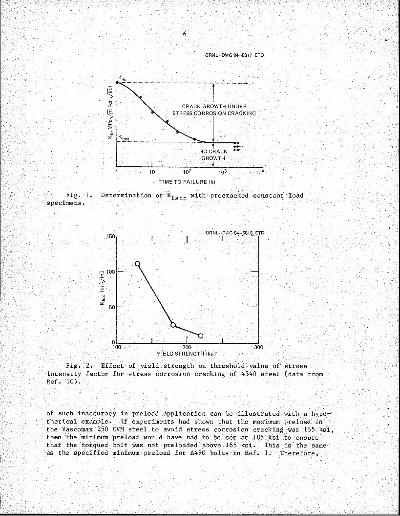
Stress corrosion cracking is a time-dependent phenomenon. Therefore, the critical stress intensity for crack propagation decreases with hold time. A schematic representation of this is shown in Fig. 1. A lower- limit value, defined as Kjgcc, is approached asymptotically as the hold time under constant stress increases.
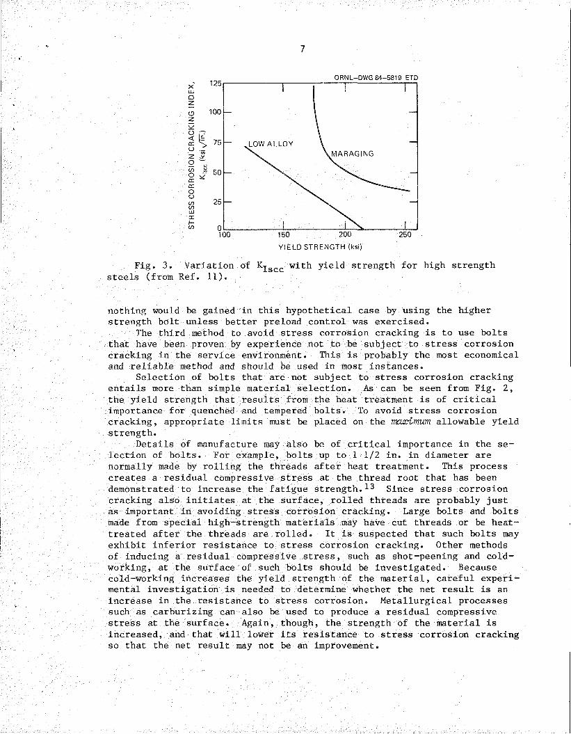
The value of Kjgcc has been shown to depend on the thermomechanical processing as well as on the material composition and environment. Imhof and Barsom10 heat-treated three pieces of 4340 steel to three different strength levels and measured their Kjgcc values in identical environments. The results from these tests are plotted in Fig. 2. A strong dependence of Kjgcc on yield strength is indicated. As a result of such evidence, reactor operators were requested11>12 to evaluate the propensity for stress corrosion cracking in material with minimum yield strength greater than 120 ksi by using Fig. 3 to estimate the value of K-j-gcc based on the yield strength.
There are three ways that stress corrosion cracking of bolts can be avoided. The first is to make sure that the environment is such that stress corrosion cannot occur. It is extremely difficult to avoid moisture at all times in an LWR plant, so that method is of little practical use. The second method is to avoid preloads that are high enough to cause stress corrosion in the operating environment. This is difficult to do if the bolt is susceptible to stress corrosion cracking. The use of calibrated wrenches is so inaccurate that the maximum preload obtained by this method may be 50% more than the minimum allowable preload. The effects
6
ORNL-DWG 84-5817 ETD
----ar~
CRACK GROWTH UNDER STRESS CORROSION CRACKING
NO CRACK GROWTH
TIME TO FAILURE (h)
Fig. 1. Determination of Kjscc with precracked constant load specimens.
ORNL-DWG 84-5818 ETD
YIELD STRENGTH (ksi)
Fig. 2. Effect of yield strength on threshold value of stress intensity factor for stress corrosion cracking of 4340 steel (data from Ref. 10).
of such inaccuracy in preload application can be illustrated with a hypothetical example. If experiments had shown that the maximum preload in the Vascomax 250 CVM steel to avoid stress corrosion cracking was 165 ksi, then the minimum preload would have had to be set at 105 ksi to ensure that the torqued bolt was not preloaded above 165 ksi. This is the same as the specified minimum preload for A490 bolts in Ref. 1. Therefore,
7
ORNL-DWG 84-5819 ETD
LOW ALLOYMARAGING
250150 200
YIELD STRENGTH (ksi)
Fig. 3. Variation of Kjgcc with yield strength for high strength steels (from Ref. 11).
nothing would be gained in this hypothetical case by using the higher strength bolt unless better preload control was exercised.
The third method to avoid stress corrosion cracking is to use bolts that have been proven by experience not to be subject to stress corrosion cracking in the service environment. This is probably the most economical and reliable method and should be used in most instances.
Selection of bolts that are not subject to stress corrosion cracking entails more than simple material selection. As can be seen from Fig. 2, the yield strength that results from the heat treatment is of critical importance for quenched and tempered bolts. To avoid stress corrosion cracking, appropriate limits must be placed on the maximum allowable yield strength.
Details of manufacture may also be of critical importance in the selection of bolts. For example, bolts up to 1 1/2 in. in diameter are normally made by rolling the threads after heat treatment. This process creates a residual compressive stress at the thread root that has been demonstrated to increase the fatigue strength.^ Since stress corrosion cracking also initiates at the surface, rolled threads are probably just as important in avoiding stress corrosion cracking. Large bolts and bolts made from special high-strength materials may have cut threads or be heat- treated after the threads are rolled. It is suspected that such bolts may exhibit inferior resistance to stress corrosion cracking. Other methods of inducing a residual compressive stress, such as shot-peening and coldworking, at the surface of such bolts should be investigated. Because cold-working increases the yield strength of the material, careful experimental investigation is needed to determine whether the net result is an increase in the resistance to stress corrosion. Metallurgical processes such as carburizing can also be used to produce a residual compressive stress at the surface. Again, though, the strength of the material is increased, and that will lower its resistance to stress corrosion cracking so that the net result may not be an improvement.

8
In those instances when a bolt must be used that is subject to stress corrosion cracking under the service conditions, the minimum and maximum allowable preloads must be determined and the bolts be tightened so that the actual preload falls within the acceptable range. Section 4 discusses preload selection, followed by a discussion on methods that can be used for applying the preload (Sect. 5).
9
4. PRELOAD RANGE SELECTION
Paragraph NF-4724 of the ASME Code2 requires that "All high strength bolts shall be preloaded to a value not less than that given in the Design Specifications." Note that the Code gives no upper limit on preload, only a lower limit. As previously discussed, the maximum preload must also be controlled when stress corrosion is a problem.
Why is it important to preload a bolt? First, it should be noted that there are two basic types of bolted joints: the pressure-containingjoint (usually gasketed) and the nonpressure-containing joint (used to connect two parts). The preload in the pressure-containing joint must be high enough to maintain sufficient contact between the mating parts (flanges) so that leakage does not occur under any service conditions.The design of such joints is discussed briefly in Chap. 8. Incidentally, failure to apply sufficient preload for this type of joint can often be detected by leakage of the joint.
The joints used for component supports and reactor vessel internals usually fall into the nonpressure-containing category. Preload is important in such joints to prevent fatigue and vibration loosening of the nut. The mechanics of preloading a bolted joint are discussed in the following section.
There are four major categories of loading of bolted joints:(1) tension, (2) axial shear, (3) eccentric shear, and (4) combined tension and shear. The behavior, analysis, and design of each of the four types of joints will be discussed further.
4.1.1 Tension joints
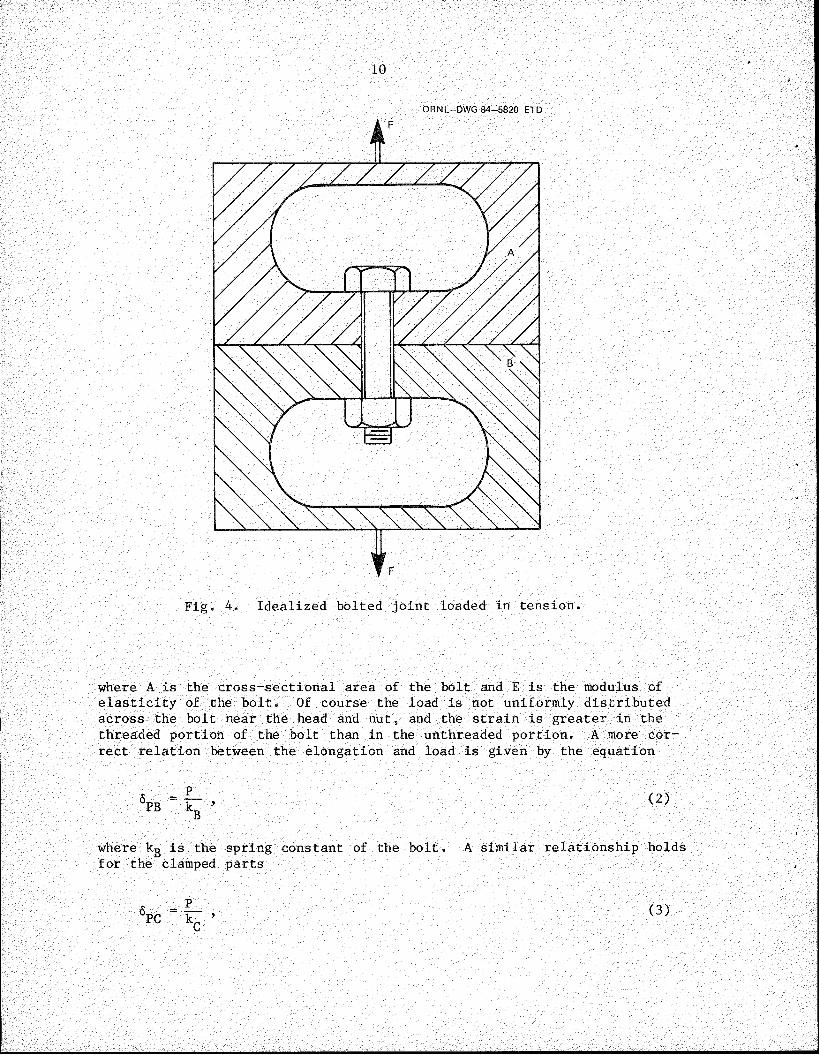
Consider the simple joint shown in Fig. 4. Parts A and B are connected by a single bolt and are subjected to a variable axial load F that acts through the center of the bolt so that no bending or prying occurs in the bolted joint. A preload P has been applied to the joint before the force F was applied. The tensile preload in the bolt is balanced by an equal and opposite compressive force between members A and B. The preload produces an elongation 6pg in the bolt and a compressive deformation 6p^ in the clamped parts A and B between the head of the bolt and the nut. Assuming the preload is low enough that the bolt and parts remain elastic, there is a linear relation between the preload P and the deformations 6pg and <$p£. The load P can be considered to be uniformly distributed through the cross section of the bolt, and the stretch 6pg can be assumed to be uniformly distributed along the length l of the bolt. The equation can be written
4.1 Principles of Bolted Joints
6 PB (1)
10
ORNL-DWG 84-5820 ETD
Fig. 4. Idealized bolted joint loaded in tension.
where A is the cross-sectional area of the bolt and E is the modulus of elasticity of the bolt. Of course the load is not uniformly distributed across the bolt near the head and nut, and the strain is greater in the threaded portion of the bolt than in the unthreaded portion. A more correct relation between the elongation and load is given by the equation
6PB (2)
where kg is the spring constant of the bolt. A similar relationship holds for the clamped parts
<5PC 9 (3)
11
where 6pQ is the compressive deformation of the clamped parts and Icq is the spring constant of the clamped parts.
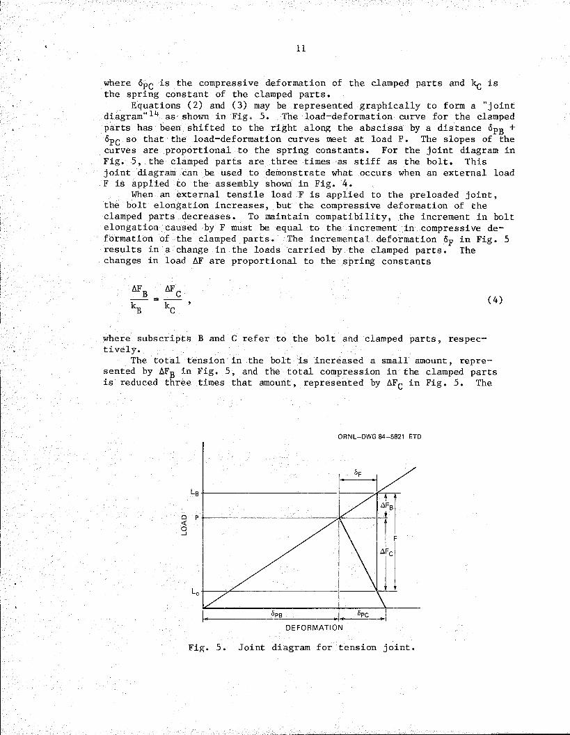
Equations (2) and (3) may be represented graphically to form a "joint diagram"14 as shown in Fig. 5. The load-deformation curve for the clamped parts has been shifted to the right along the abscissa by a distance 6pg + SpQ so that the load-deformation curves meet at load P. The slopes of the curves are proportional to the spring constants. For the joint diagram in Fig. 5, the clamped parts are three times as stiff as the bolt. This joint diagram can be used to demonstrate what occurs when an external load F is applied to the assembly shown in Fig. 4.
When an external tensile load F is applied to the preloaded joint, the bolt elongation increases, but the compressive deformation of the clamped parts decreases. To maintain compatibility, the increment in bolt elongation caused by F must be equal to the increment in compressive deformation of the clamped parts. The incremental deformation Sp in Fig. 5 results in a change in the loads carried by the clamped parts. The changes in load AF are proportional to the spring constants
AF
h
B (4)
where subscripts B and C refer to the bolt and clamped parts, respectively.
The total tension in the bolt is increased a small amount, represented by AFg in Fig. 5, and the total compression in the clamped parts is reduced three times that amount, represented by AF^-. in Fig. 5. The
ORNL-DWG 84-5821 ETD
Q P
DEFORMATION
Fig. 5. Joint diagram for tension joint.
12
total tension in the bolt Lg is
kB + kCF + P , (5)
and the total compression in the clamped part is
kB + kCF - P . (6)
When the stiffness of the clamped parts is three times the stiffness of the bolt, as in the example shown in Fig. 5, that is,
kC = 3kB ’ (7)
then Eqs. (5) and (6) become
lb F + P (8)
and
LC (9)
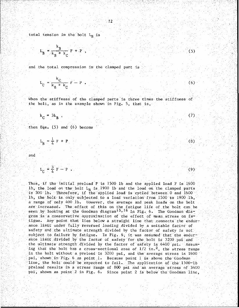
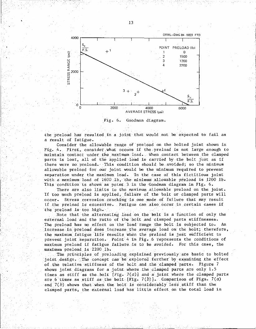
Thus, if the initial preload P is 1500 lb and the applied load F is 1600 lb, the load on the bolt Lg is 1900 lb and the load on the clamped parts is 300 lb. Therefore, if the applied load is cycled between 0 and 1600 lb, the bolt is only subjected to a load variation from 1500 to 1900 lb, a range of only 400 lb. However, the average and peak loads on the bolt are increased. The effect of this on the fatigue life of the bolt can be seen by looking at the Goodman diagram^5> ^ in Fig. 6. The Goodman diagram is a conservative approximation of the effect of mean stress on fatigue. Any point that lies below a straight line that connects the endurance limit under fully reversed loading divided by a suitable factor of safety and the ultimate strength divided by the factor of safety is not subject to failure by fatigue. In Fig. 6, it was assumed that the endurance limit divided by the factor of safety for the bolt is 3200 psi and the ultimate strength divided by the factor of safety is 6400 psi. Assuming that the bolt has a cross-sectional area of 1/2 in.2, the stress range in the bolt without a preload is 3200 psi, and the average stress is 1600 psi, shown in Fig. 6 as point 1. Because point 1 is above the Goodman line, the bolt could be expected to fail. The application of the 1500-lb preload results in a stress range of 800 psi and an average stress of 3400 psi, shown as point 2 in Fig. 6. Since point 2 is below the Goodman line,
13
ORNL-DWG 84-5822 ETD
POINT PRELOAD (lb)
4000AVERAGE STRESS (psi)
6000
Fig. 6. Goodman diagram.
the preload has resulted in a joint that would not be expected to fail as a result of fatigue.
Consider the allowable range of preload on the bolted joint shown in Fig. 4. First, consider what occurs if the preload is not large enough to maintain contact under the maximum load. When contact between the clamped parts is lost, all of the applied load is carried by the bolt just as if there were no preload. This condition should be avoided; so the minimum allowable preload for our joint would be the minimum required to prevent separation under the maximum load. In the case of this fictitious joint with a maximum load of 1600 lb, the minimum allowable preload is 1200 lb. This condition is shown as point 3 in the Goodman diagram in Fig. 6.
There are also limits to the maximum allowable preload on the joint. If too much preload is applied, failure of the bolt or clamped parts will occur. Stress corrosion cracking is one mode of failure that may result if the preload is excessive. Fatigue can also occur in certain cases if the preload is too high.
Note that the alternating load on the bolt is a function of only the external load and the ratio of the bolt and clamped parts stiffnesses.The preload has no effect on the load range the bolt is subjected to. An increase in preload does increase the average load on the bolt; therefore, the maximum fatigue life results when the preload is just sufficient to prevent joint separation. Point 4 in Fig. 6 represents the conditions of maximum preload if fatigue failure is to be avoided. For this case, the maximum preload is 2200 lb.
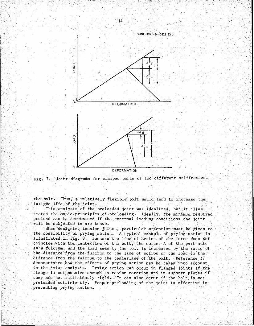
The principles of preloading explained previously are basic to bolted joint design. The concept can be explored further by examining the effect of the relative stiffness of the bolt and the clamped parts. Figure 7 shows joint diagrams for a joint where the clamped parts are only 1.5times as stiff as the bolt [Fig. 7(a)] and a joint where the clamped partsare 6 times as stiff as the bolt [Fig. 7(b)]. Comparison of Figs. 7(a)and 7(b) shows that when the bolt is considerably less stiff than theclamped parts, the external load has little effect on the total load in
14
ORNL-DWG 84-5823 ETD
DEFORMATION
DEFORMATION
Fig. 7. Joint diagrams for clamped parts of two different stiffnesses.
the bolt. Thus, a relatively flexible bolt would tend to increase the fatigue life of the joint.
This analysis of the preloaded joint was idealized, but it illustrates the basic principles of preloading. Ideally, the minimum required preload can be determined if the external loading conditions the joint will be subjected to are known.
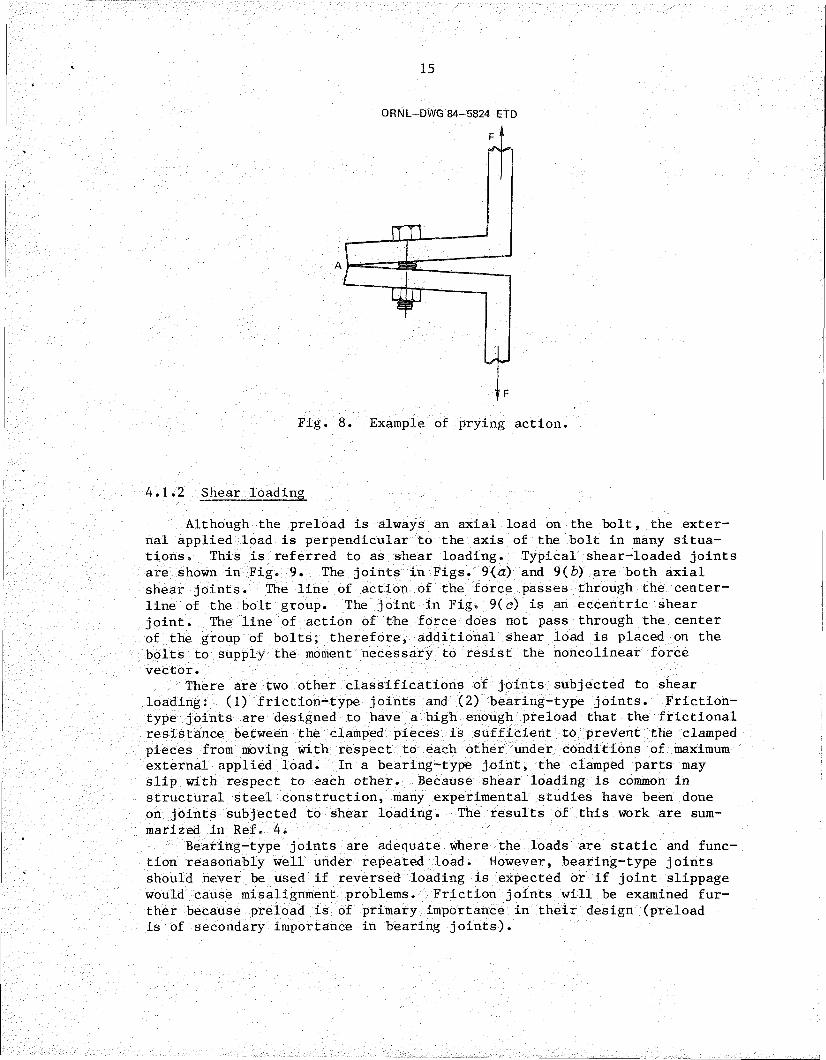
When designing tension joints, particular attention must be given to the possibility of prying action. A typical example of prying action is illustrated in Fig. 8. Because the line of action of the force does not coincide with the centerline of the bolt, the corner A of the part acts as a fulcrum, and the load seen by the bolt is increased by the ratio of the distance from the fulcrum to the line of action of the load to the distance from the fulcrum to the centerline of the bolt. Reference 17 demonstrates how the effects of prying action may be taken into account in the joint analysis. Prying action can occur in flanged joints if the flange is not massive enough to resist rotation and in support plates if they are not sufficiently rigid. It can also occur if the bolt is not preloaded sufficiently. Proper preloading of the joint is effective in preventing prying action.
15
ORNL-DWG 84-5824 ETD
Fig. 8. Example of prying action.
4.1.2 Shear loading
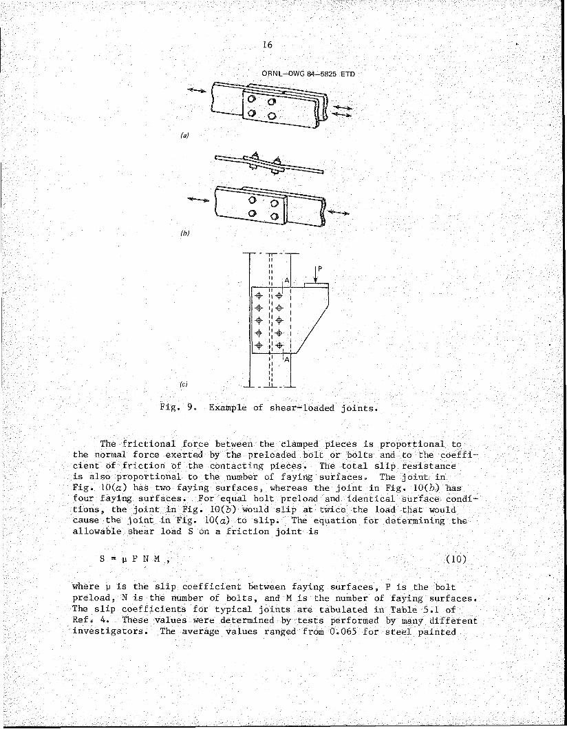
Although the preload is always an axial load on the bolt, the external applied load is perpendicular to the axis of the bolt in many situations. This is referred to as shear loading. Typical shear-loaded joints are shown in Fig. 9. The joints in Figs. 9(a) and 9(£>) are both axial shear joints. The line of action of the force passes through the center- line of the bolt group. The joint in Fig. 9(c) is an eccentric shear joint. The line of action of the force does not pass through the center of the group of bolts; therefore, additional shear load is placed on the bolts to supply the moment necessary to resist the noncolinear force vector.
There are two other classifications of joints subjected to shear loading: (1) friction-type joints and (2) bearing-type joints. Friction-type joints are designed to have a high enough preload that the frictional resistance between the clamped pieces is sufficient to prevent the clamped pieces from moving with respect to each other under conditions of maximum external applied load. In a bearing-type joint, the clamped parts may slip with respect to each other. Because shear loading is common in structural steel construction, many experimental studies have been done on joints subjected to shear loading. The results of this work are summarized in Ref. 4.
Bearing-type joints are adequate where the loads are static and function reasonably well under repeated load. However, bearing-type joints should never be used if reversed loading is expected or if joint slippage would cause misalignment problems. Friction joints will be examined further because preload is of primary importance in their design (preload is of secondary importance in bearing joints).
16
(b)
(c)
o o
Fig. 9. Example of shear-loaded joints.
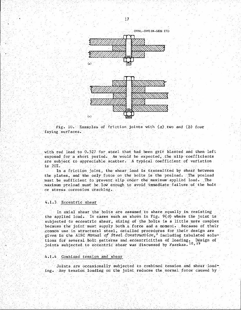
The frictional force between the clamped pieces is proportional to the normal force exerted by the preloaded bolt or bolts and to the coefficient of friction of the contacting pieces. The total slip resistance is also proportional to the number of faying surfaces. The joint in Fig. 10(a) has two faying surfaces, whereas the joint in Fig. 10(b) has four faying surfaces. For equal bolt preload and identical surface conditions , the joint in Fig. 10(b) would slip at twice the load that would cause the joint in Fig. 10(a) to slip. The equation for determining the allowable shear load S on a friction joint is
S = p P N M , (10)where p is the slip coefficient between faying surfaces, P is the bolt preload, N is the number of bolts, and M is the number of faying surfaces. The slip coefficients for typical joints are tabulated in Table 5.1 of Ref. 4. These values were determined by tests performed by many different investigators. The average values ranged from 0.065 for steel painted
17
ORNL-DWG 84-5826 ETD
mmmmi v/m^ m
__
L(a} J J
1W///////W///, yM.
Wm WmmmmV/////////////M y//M
HIs J
Fig. 10. Examples of friction joints with (a) two and (&) four faying surfaces.
with red lead to 0.527 for steel that had been grit blasted and then left exposed for a short period. As would be expected, the slip coefficients are subject to appreciable scatter. A typical coefficient of variation is 20%.
In a friction joint, the shear load is transmitted by shear between the plates, and the only force on the bolts is the preload. The preload must be sufficient to prevent slip under the maximum applied load. The maximum preload must be low enough to avoid immediate failure of the bolt or stress corrosion cracking.
4.1.3 Eccentric shear
In axial shear the bolts are assumed to share equally in resisting the applied load. In cases such as shown in Fig. 9(e) where the joint is subjected to eccentric shear, sizing of the bolts is a little more complex because the joint must supply both a force and a moment. Because of their common use in structural steel, detailed procedures for their design are given in the AISC Manual of Steel Construction^ including tabulated solutions for several bolt patterns and eccentricities of loading. Design of joints subjected to eccentric shear was discussed by Fazekas.^
4.1.4 Combined tension and shear
Joints are occasionally subjected to combined tension and shear loading. Any tension loading on the joint reduces the normal force caused by
18
preload and, therefore, directly reduces the shear loading that will produce slip. In friction joints, the preload must be high enough that the net normal force on the joint is sufficient to ensure that slip cannot occur.
In the case of bearing joints, the bolts will see a shear stress and a tension stress. The combination of shear and tension stress that the bolt is subjected to in such joints should be limited by the following equation^
—----+ y2 < 1 , (11)(0.62)2
where x is the ratio of the shear stress to the allowable tensile strength, and y is the ratio of the tensile stress to the allowable tensile strength. This equation was determined empirically.20
4.2 Joint Stiffness
As discussed previously, the behavior of tension joints is strongly influenced by the stiffness of the clamped parts relative to the bolt.The amount of load fluctuation seen by the bolt decreases in proportion to the decrease in the stiffness of the bolt relative to the stiffness of the clamped parts. Detailed studies of fatigue in bolted joints often end up with recommendations for "elasticated” bolts2^ that are less stiff than normal bolts.
The stiffness of the bolt can be calculated by estimating the total length change per unit load. The spring constant kg is the reciprocal of the total length change per unit load. The threaded length of the bolt is not as stiff as the unthreaded portion of the bolt. Some additional deformation occurs in the head of the bolt and in the nut. For purposes of estimating the bolt stiffness, the effective lengths of the unthreaded and threaded portions of the bolt are increased somewhat to account for the deformation in the head and nut, respectively. Bickford22 recommends that the unthreaded length be increased by one-half the thickness of the head and that the threaded length be increased by one-half the thickness of the nut. The threaded length is the length up to the point that the threads enter the nut. Therefore, the stiffness of the bolt is given by
1 lg + 0.5 tH 1T + 0.5 tN kg E Ag + E Aj (12)
where lg is the distance from the head to the threads, tg is the thickness of the head, E is the modulus of elasticity of the bolt, Ag is the cross- sectional area of the unthreaded portion of the bolt, Lj is the distance from the beginning of the threads to the nut, tjj is the thickness of the nut, and Ay is the effective stress area of the threaded portion of the bolt. The threaded portion of the bolt does not have a uniform diameter,

194
so the proper cross-sectional area to use is not evident. The effective stress area is the area that gives the same value for ultimate tensile strength S as measured in a specimen of uniform diameter when the formula
S T_AX
(13)
is used, where T is the tensile load that breaks the bolt. Screw Thread Standards for Federal Services1^ provides a formula for calculating stress area:
AT = 3.1416 3H16
2
or
AT 0.7854 D - 0.9743n
2»
(14)
(15)
where E is the basic pitch diameter, D is the basic major diameter, n is the number of threads per inch, and H is 0.866025/n. The standard states that Eq. (14) is applicable to steels up to 180,000 psi ultimate tensile strength. For higher strength steels, it recommends the minimum pitch diameter E^.n for the class of thread specified be used. The formula becomes
AT 3.1416E . min
2
3H \2Tb (16)
Now consider the stiffness of the joint. Much of the work on joint stiffness has been done in Germany, Russia, and Egypt. The procedure used for estimating the stiffness of the clamped parts is to assume that the load is carried by the portion of the clamped parts that lies within a conical volume extending from the outer diameter of the contacting surface of the head and bolt. The German standard VDI 2230: Systematic Calculation of High Duty Bolted Joints*’7 provides equations for estimating the stiffness of concentric clamped parts that are concentrically loaded and firmly stacked. The stiffness of the firmly clamped parts k^ is given by
kCTIE
= a — D 2) + B 'irE8l
\ A +5 100 (17)
20
for < D. < Sd^, where d^ is the diameter of the bolt head or nut surface that bears on the clamped parts, Dg is the diameter of the hole, D. is the diameter of the clamped parts, & is the combined thickness of the clamped parts, and E is the modulus of elasticity of the clamped parts. For clamped parts with a diameter more than 3 times the diameter of the bolt head or nut bearing area.
Equations (17) and (18) are only valid if the clamped parts are in uniform firm contact. The stiffness will be less if there is not uniform contact• Furthermore, if the line of action of the external load on the joint is not in line with the centerline of the bolt, the stiffness of the clamped parts is decreased.
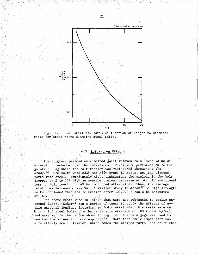
The German standard VDI 2230: Systematic Calculation of High DutyBolted Joints (Ref. 17) contains a nomograph that gives values of the ratio of the bolt spring constant to the sum of the spring constants for the bolt and clamped parts for joints of various clamping lengths, for both full and reduced shank bolts and for steel, cast iron, and aluminum. The plot of kg/(kg + k^) vs the length-to-diameter ratio shown in Fig. 11 was obtained from the nomograph in VDI-2230, which was also included in Ref. 24. This plot can be useful to the designer for estimating the stiffness of the joint. Bickford25 developed plots of k^/kg vs %/d using the VDI-2230 nomograph and the work of Motosh.25 The plots based on these two sources are in good agreement. Figure 11 should only be used for joints without gaskets and for steel parts and bolts.
More recent work27»28 on the determination of the stiffness of the clamped parts in bolted joints has made use of finite-element analyses.The joint consisted of two steel plates in the form of circular cylinders of equal thickness with a single bolt through the center. Effects of plate diameter, plate thickness, bolt head height, and bolt head thickness were examined. It was discovered that the stiffness of the clamped parts increased with plate diameter Dj up to a value of 3.5 times the bolt diameter d and was constant for larger diameters. The stiffness of the clamped parts decreased as the joint thickness i increased until it reached a minimum for %/d = 2.75. The stiffness of the clamped parts then increased until it approached a constant value for i/d > 10. The bolt geometry had a negligible effect on the stiffness.
This discussion of joint behavior has thus far considered linear- elastic behavior of the bolt and clamped part. Actual joint behavior is nonlinear, especially at low and very high loads. The initial behavior is nonlinear because initial contact is at points that must deform or wear down until a surface contact results.29»30 This change in actual contact area as the load increases from zero is nonlinear. This effect diminishes as the load is increased, and there is a portion of the load-deformation diagram that approaches linearity. At still higher loads the nonlinearity increases as local yielding increases.
(18)
21
ORNL-DWG 84-5827 ETD
e/d
Fig. 11. Joint stiffness ratio as function of length-to-diameter ratio for steel bolts clamping steel parts.
4.3 Relaxation Effects
The original preload on a bolted joint relaxes to a lower value as a result of embedment at the interfaces. Tests were performed on bolted joints during which the bolt tension was registered throughout the study.31 The bolts were A325 and A354 grade BD bolts, and the clamped parts were steel. Immediately after tightening, the preload in the bolt dropped by 2 to 11% with an average preload decrease of 5%. An additional loss in bolt tension of 4% had occurred after 21 d. Thus, the average total loss in tension was 9%. A similar study in Japan32 on high-strength bolts concluded that the relaxation after 100,000 h could be estimated at ~6%.
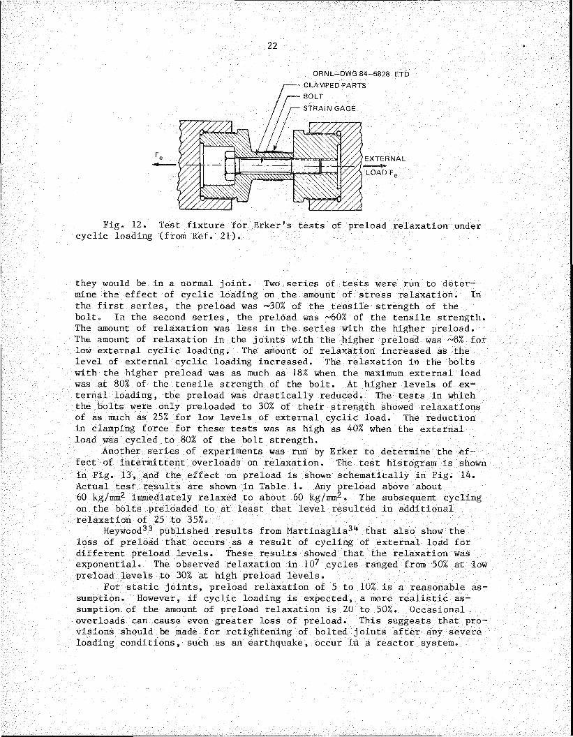
The above tests were on joints that were not subjected to cyclic external loads. Erker21 ran a series of tests to study the effects of cyclic external loading, including periodic overloads. His tests were on M 14 x 1.5 steel bolts that had a tensile strength of 100 to 120 kg/mm2 and were run in the device shown in Fig. 12. A strain gage was used to monitor the stress in the clamped part. Note that the clamped part has a relatively small diameter, which makes the clamped parts less stiff than
22
ORNL-DWG 84-5828 ETD
CLAMPED PARTS BOLTSTRAIN GAGE
EXTERNAL
LOAD Fe
Fig. 12. Test fixture for Erker's tests of preload relaxation under cyclic loading (from Ref. 21).
they would be in a normal joint. Two series of tests were run to determine the effect of cyclic loading on the amount of stress relaxation. In the first series, the preload was ~30% of the tensile strength of the bolt. In the second series, the preload was ~60% of the tensile strength. The amount of relaxation was less in the series with the higher preload. The amount of relaxation in the joints with the higher preload was ~8% for low external cyclic loading. The amount of relaxation increased as the level of external cyclic loading increased. The relaxation in the bolts with the higher preload was as much as 18% when the maximum external load was at 80% of the tensile strength of the bolt. At higher levels of external loading, the preload was drastically reduced. The tests in which the bolts were only preloaded to 30% of their strength showed relaxations of as much as 25% for low levels of external cyclic load. The reduction in clamping force for these tests was as high as 40% when the external load was cycled to 80% of the bolt strength.
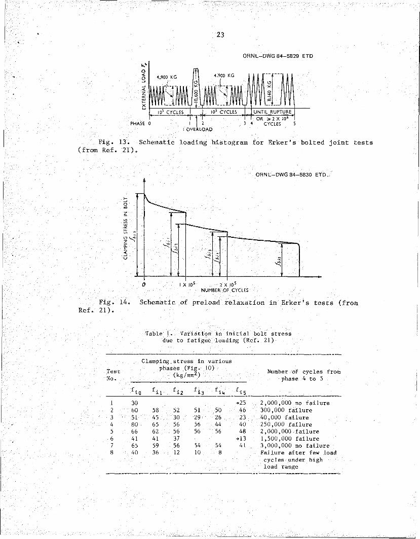
Another series of experiments was run by Erker to determine the effect of intermittent overloads on relaxation. The test histogram is shown in Fig. 13, and the effect on preload is shown schematically in Fig. 14. Actual test results are shown in Table 1. Any preload above about 60 kg/mm2 immediately relaxed to about 60 kg/mm2. The subsequent cycling on the bolts preloaded to at least that level resulted in additional relaxation of 25 to 35%.
Heywood^3 published results from Martinaglia3tf that also show the loss of preload that occurs as a result of cycling of external load for different preload levels. These results showed that the relaxation was exponential. The observed relaxation in 102 cycles ranged from 50% at low preload levels to 30% at high preload levels.
For static joints, preload relaxation of 5 to 10% is a reasonable assumption. However, if cyclic loading is expected, a more realistic assumption of the amount of preload relaxation is 20 to 50%. Occasional . overloads can cause even greater loss of preload. This suggests that provisions should be made for retightening of bolted joints after any severe loading conditions, such as an earthquake, occur in a reactor system.
23
ORNL-DWG 84-5829 ETD
4,900 KG4,900 KG
10s CYCLES I05 CYCLES UNTIL RUPTUREOR ^ 2 X 10s
CYCLESPHASE 0OVERLOAD
Fig. 13. Schematic loading histogram for Erker's bolted joint tests (from Ref. 21).
ORNL-DWG 84-5830 ETD
NUMBER OF CYCLES
Fig. 14. Schematic of preload relaxation in Erker's tests (from Ref. 21).
Table 1. Variation in initial bolt stress due to fatigue loading (Ref. 21)
TestNo.
Clamping stress in phases (Fig.
(kg/mm2)
fi0 fi1 fi2 fi3
various10)
fi4 fi5
Number of cycles from phase 4 to 5
1 30 +25 2,000,000 no failure2 60 58 52 51 50 46 300,000 failure3 51 45 30 29 26 23 40,000 failure4 80 65 56 56 44 40 250,000 failure5 66 62 56 56 56 48 2,000,000 failure6 41 41 37 +13 1,500,000 failure7 65 59 56 54 54 41 3,000,000 no failure8 40 36 12 10 8 Failure after few load
cycles under highload range

24
Another condition that should be considered when the amount of relaxation is being estimated is the effect of thermal gradients or different temperatures in different components of the bolted joints. Such conditions can result in self-equilibrating forces within the joint that promote relaxation of the preload.
4.4 Selection of Preload
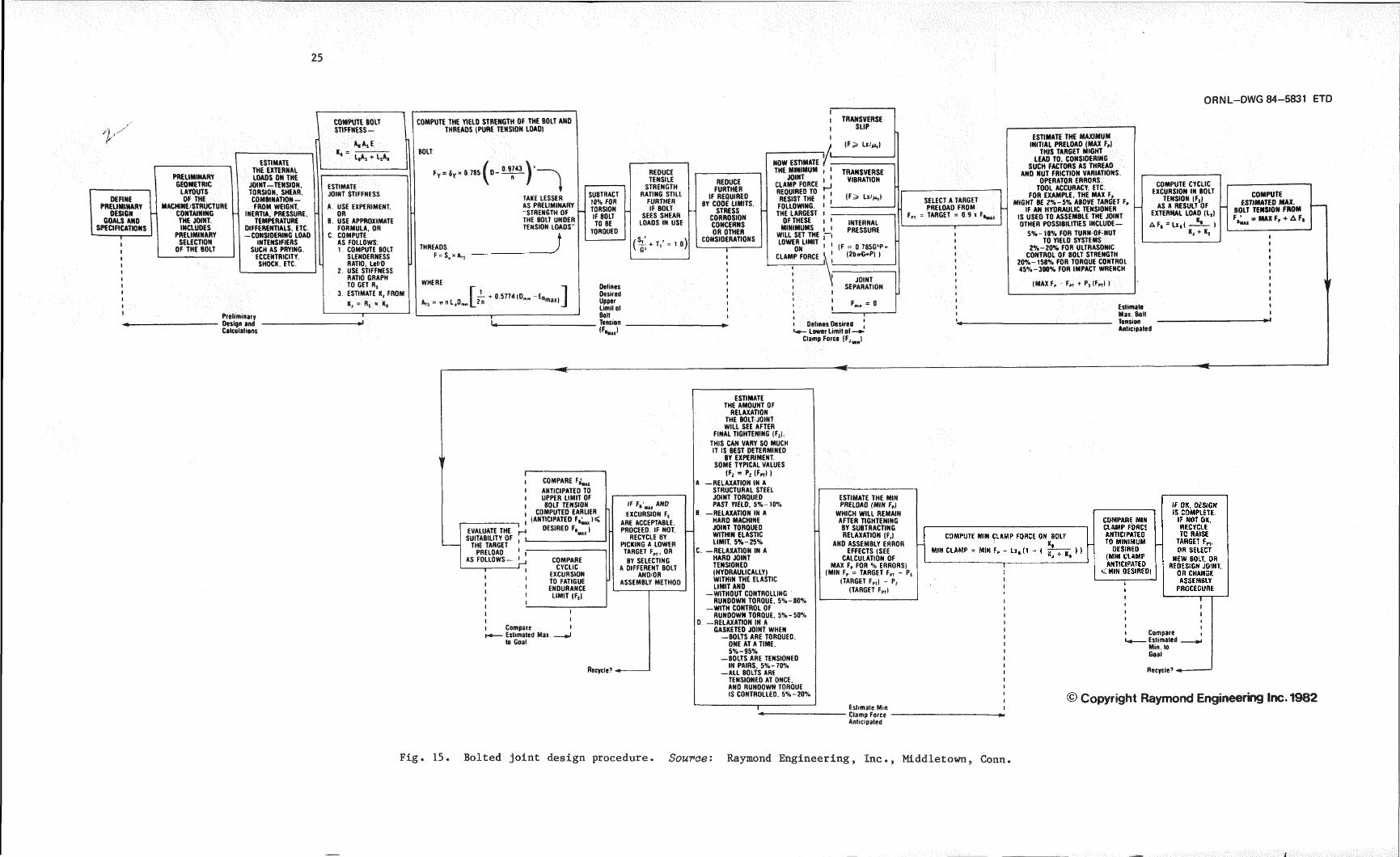
Various aspects of bolted joint design and preload selection have been discussed. The designer must consider all these aspects to arrive at a properly designed joint. John Bickford of Raymond Engineering, Inc., developed the flowchart in Fig. 15 to aid the designer in this process.A modified version of the chart was published in Ref. 35. The accuracy of the method used for preloading the bolts must be taken into account, as pointed out in Fig. 15. The methods for applying preload and their accuracies are addressed in the following section.
An alternative unified procedure for designing bolted joints is given in Ref. 17 and consists of the following ten steps.
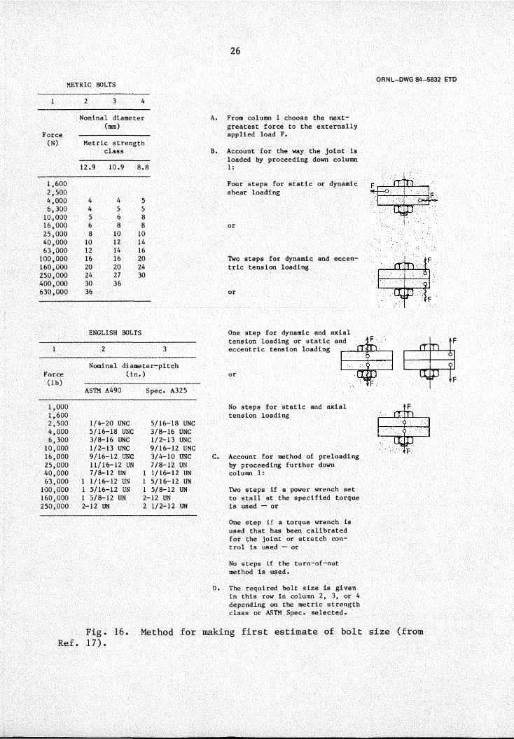
1. Make an initial estimation of bolt diameter and joint thickness and determine whether the bearing stress under the bolt head when a preload equal to 90% of the yield strength of the bolt is applied exceeds the bearing capacity of the material the clamped parts are made from. If the bearing capacity of the material is exceeded, appropriate hardened washers may be required. Figure 16 provides a convenient method for making the initial estimate of the diameter bolt required.
2. The method of applying and controlling preload is selected. A tightening factor is then determined from Table 2. The tightening factor is defined as the ratio of the maximum preload that might be achieved to the minimum preload that might be achieved using a particular preloading method. The tightening factor is not applicable to tightening procedures that reach or exceed the yield strength of the bolt.
3. Determine the minimum required preload Pr, taking into account thefollowing considerations: (a) preload must be sufficient to resistany shear loading in a friction-type joint, (b) preload must be sufficient to seal pressure-retaining joints, and (c) preload must be high enough to prevent one-sided lift-off under prying action.
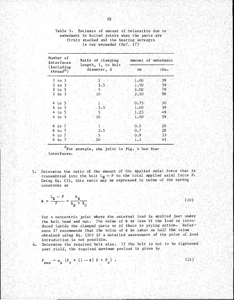
4. The amount of preload loss caused by embedment Pz should be determined using the expression
where fz is the amount of embedment estimated using Table 3 and kg and k^ are the spring constants of the bolt and clamped parts, respectively.
25
ORNL-DWG 84-5831 ETD
DEFINE PRELIMINARY
DESIGN GOALS AND
SPECIFICATIONSI
COMPUTE BOLT \STIFFNESS-
| Ms*
ESTIMATE1 8 L|AS + LsA9
PRELIMINARYTHE EXTERNALLOADS ON THE 1----------------------------------------GEOMETRIC JOINT-TENSION. ESTIMATE
LAYOUTS TORSION. SHEAR. JOINT STIFFNESSOF THE COMBINATION-
MACHINE/STRUCTURE FROM WEIGHT. A. USE EXPERIMENT.CONTAINING INERTIA, PRESSURE. ORTHE JOINT. TEMPERATURE B. USE APPROXIMATEINCLUDES DIFFERENTIALS. ETC. FORMULA. OR
PRELIMINARY -CONSIDERING LOAD C COMPUTESELECTION INTENSIFIERS AS FOLLOWS:
OF THE BOLT SUCH AS PRYING. ECCENTRICITY.
1 COMPUTE BOLTSLENDERNESS
SHOCK. ETC. L RATIO. Lel/O2 USE STIFFNESS
RATIO GRAPHTO GET R,
3 ESTIMATE Kj FROM
Ki = Rs * A.
COMPUTE THE YIELD STRENGTH OF THE BOLT AND THREADS (PURE TENSION LOAD)
BOLT:
Fy = Sy » 0.785 I 0
THREADSF” S, x ats
TAKE LESSER AS PRELIMINARY
STRENGTH OF THE BOLT UNDER TENSION LOADS"
WHERE
Priltiniiufy Design andCalculations
SUBTRACT 18% FOR TORSION IF BOLT TO BE
TOROUEO
REDUCE TENSILE
STRENGTH RATING STILL
FURTHER IF BOLT
SEES SHEAR LOADS IN USE
(Si + T,' = 10)
REDUCE FURTHER
IF REQUIRED BY CODE LIMITS.
STRESS CORROSION CONCERNS OR OTHER
CONSIDERATIONS
DelinesDesired Upper Limit st BoltTension
I TRANSVERSE l SLIP
NOW ESTIMATE THE MINIMUM
JOINTCLAMP FORCE REQUIRED TO RESIST THE
FOLLOWING. THE LARGEST
OF THESEmBmFnvTOv
WILL SET THE LOWER LIMIT
ONCLAMP FORCE
£
(F> Lx/m,)
i 1 TRANSVERSE I 1 VIBRATION
t-Ji ' (F> Lx/m,)
INTERNALPRESSURE
(F = 0 785G'P + (2bfrG»P) )
JOINTSEPARATION
Defines Desired ,Lower Limit ol —®-
Clamp Force (FJm-)
SELECT A TARGET PRELOAD FROM
F„ = TARGET = 0.9 x F,
ESTIMATE THE MAXIMUM INITIAL PRELOAD (MAX F,)
THIS TARGET MIGHT LEAD TO, CONSIDERING
SUCH FACTORS AS THREAD AND NUT FRICTION VARIATIONS.
OPERATOR ERRORS,TOOL ACCURACY. ETC.
FOR EXAMPLE. THE MAX F, SIGHT BE 2%-S% ABOVE TARGET F,
IF AN HYDRAULIC TENSIONER IS USED TO ASSEMBLE THE JOINT OTHER POSSIBILITIES INCLUDE—
5%-10% FOR TURN-OF-NUT TO YIELD SYSTEMS
2%-20% FOR ULTRASONIC CONTROL OF BOLT STRENGTH
20%-150% FOR TORQUE CONTROL 45%-300% FOR IMPACT WRENCH
(MAX F, - F„ + PS|F„) )
COMPUTE CYCLIC EXCURSION IN BOLT
TENSION (F,)AS A RESULT OF
EXTERNAL LOAD (L„)
AF, =Lx,( —)Kj + K,
COMPUTE ESTIMATED MAX.
BOLT TENSION FROM
= mX +3
iI
Estimate Mai. Bolt
Anticipated
1 f
EVALUATE THE SUITABILITY OF
THE TARGET PRELOAD
AS FOLLOWS —
illtI(
1 «Hl *- I -
H
COMPARE F^,
ANTICIPATED TO UPPER LIMIT OF BOLT TENSION
COMPUTED EARLIER (ANTICIPATED F^K
DESIRED F,^)
COMPARE CYCLIC
EXCURSION TO FATIGUE ENDURANCE LIMIT (Fe)
IF F,'^ AND
EXCURSION F, ARE ACCEPTABLE. PROCEED IF NOT.
RECYCLE BY PICKING A LOWER TARGET F„, OR
BY SELECTING A DIFFERENT BOLT
AND/ORASSEMBLY METHOD
II
Compare •• Estimated Max ___ »J
to Goal
Recycle?
ESTIMATE THE AMOUNT OF
RELAXATION THE BOLT/JOINT WILL SEE AFTER
FINAL TIGHTENING (F;).
THIS CAN VARY SO MUCH IT IS BEST DETERMINED
BY EXPERIMENT SOME TYPICAL VALUES
(F, = Pj (Fpr) )A —RELAXATION IN A
STRUCTURAL STEEL JOINT TOROUED PAST YIELD, 5%-m
B. —RELAXATION IN AHARD MACHINE JOINT TOROUEO WITHIN ELASTIC LIMIT. 5%-25%
C. —RELAXATION IN AHARO JOINT TENSIONED (HYDRAULICALLY)WITHIN THE ELASTIC LIMIT AND
—WITHOUT CONTROLLING RUNDOWN TORQUE. 5%-80%
-WITH CONTROL OF RUNDOWN TORQUE. 5%-50%
0 -RELAXATION IN AGASKETED JOINT WHEN
—BOLTS ARE TOROUED.ONE AT A TIME.5%-95%
—BOLTS ARE TENSIONED IN PAIRS. 5%-70%
—ALL BOLTS ARE TENSIONED AT ONCE.AND RUNDOWN TORQUE IS CONTROLLED. 5%-20%
T
ESTIMATE THE MIN PRELOAD (MIN F,)
WHICH WILL REMAIN AFTER TIGHTENING BY SUBTRACTING RELAXATION (F,|
AND ASSEMBLY ERROR EFFECTS (SEE
CALCULATION OF MAX Fp FOR % ERRORS)
(MIN Fp = TARGET F„ - Ps (TARGET Fp,) - P,
(TARGET Fpt)
Estimate Mm Clamp Force Anticipated
COMPARE MIN CLAMP FORCE ANTICIPATED TO MINIMUM
DESIRED (MIN CLAMP ANTICIPATED
<MIN DESIRED)
COMPUTE MIN CLAMP FORCE ON BOLT
MIN CLAMP = MIN F, - Lx, (1 - (
IF OK. DESIGNIS COMPLETE
IF NOT OK. RECYCLE TO RAISE
TARGET Fp,.OR SELECT
NEW BOLT. OR REDESIGN JOINT.
OR CHANGE ASSEMBLY
PROCEDURE
i
i CompareLa____ Estimated
Min.to Goal
Recycle? «
© Copyright Raymond Engineering Inc. 1982
Fig 15. Bolted joint design procedure• Source: Raymond Engineering Inc., Middletown Conn
iL
26
METRIC BOLTS ORNL-DWG 84-5832 ETD
Force(N)
Nominal diameter (mm)
Metric strength class
12.9 10.9 8.81,6002,5004,000 4 4 56,300 4 5 510,000 5 6 816,000 6 8 825,000 8 10 1040,000 10 12 1463,000 12 14 16100,000 16 16 20160,000 20 20 24250,000 24 27 30400,000 30 36630,000 36
A. From column 1 choose the next- greatest force to the externally applied load F.
B. Account for the way the joint is loaded by proceeding down column 1:
Four steps for static or dynamic shear loading
Two steps for dynamic and eccentric tension loading
ENGLISH BOLTS1 2 3
Nominal diameter-pitchForce(lb)
(in. )ASTM A490 Spec. A325
1,0001,6002,500 1/4-20 UNC 5/16-18 UNC4,000 5/16-18 UNC 3/8-16 UNC6,300 3/8-16 UNC 1/2-13 UNC10,000 1/2-13 UNC 9/16-12 UNC16,000 9/16-12 UNC 3/4-10 UNC25,000 11/16-12 UN 7/8-12 UN40,000 7/8-12 UN 1 1/16-12 UN63,000 1 1/16-12 UN 1 5/16-12 UN100,000 1 5/16-12 UN 1 5/8-12 UN160,000 1 5/8-12 UN 2-12 UN250,000 2-12 UN 2 1/2-12 UN
One step for dynamic and axial tension loading or static and eccentric tension loading
No steps for static and axial tension loading
C. Account for method of preloading by proceeding further down column 1:Two steps if a power wrench set to stall at the specified torque is used — orOne step if a torque wrench is used that has been calibrated for the joint or stretch control is used — orNo steps if the tum-of-nut method is used.
D. The required bolt size is given in this row in column 2, 3, or 4 depending on the metric strength class or ASTM Spec, selected.
rrD f6
9
■F
^ If
Ref.Fig.17).
16. Method for making first estimate of bolt size (from
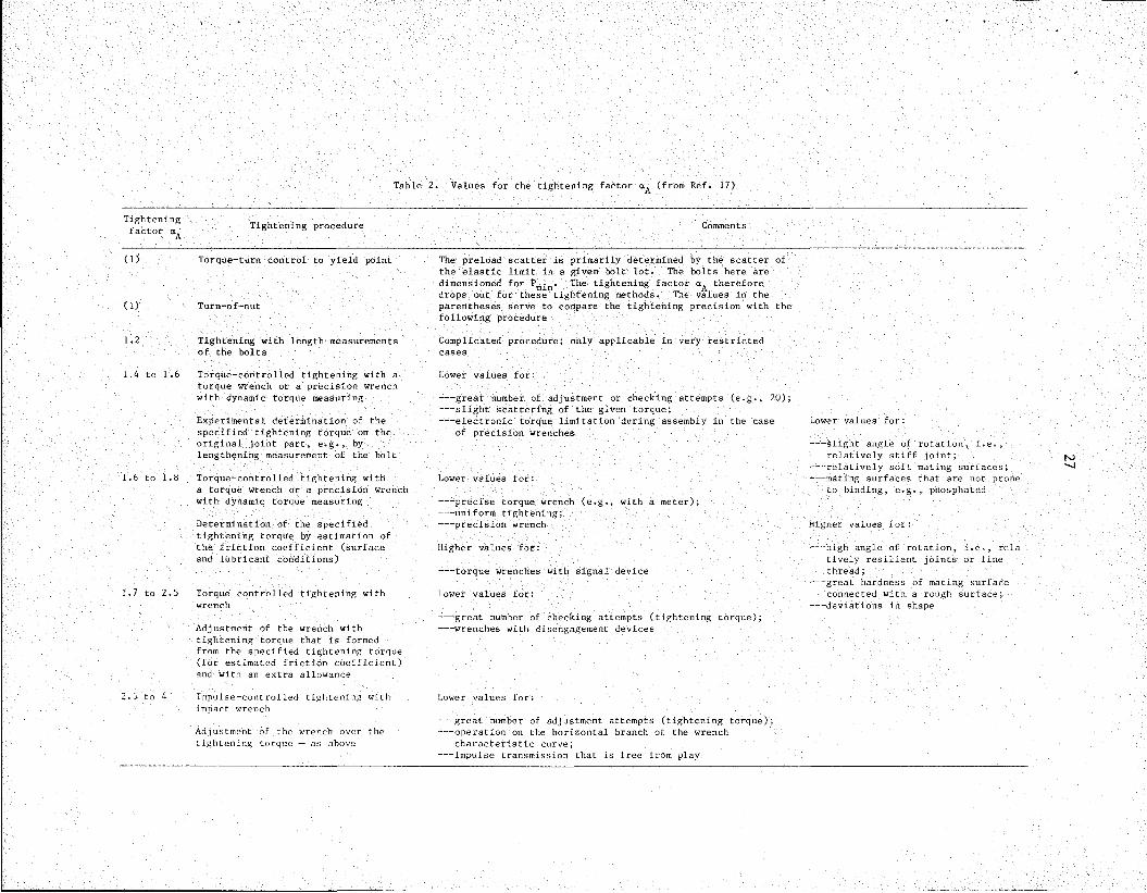
Table 2. Values for the tightening factor (from Ref. 17)
Tighteningfactor Tightening procedure Comments
(1) Torque-turn control to yield point
(1) Turn-of-nut
1.2 Tightening with length measurementsof the bolts
1.4 to 1.6 Torque-controlled tightening with a torque wrench or a precision wrench with dynamic torque measuring
Experimental determination of the specified tightening torque on the original joint part, e.g., by lengthening measurement of the bolt
1.6 to 1.8 Torque-controlled tightening witha torque wrench or a precision wrench with dynamic torque measuring
Determination of the specified tightening torque by estimation of the friction coefficient (surface and lubricant conditions)
1.7 to 2.5 Torque controlled tightening with wrench
Adjustment of the wrench with tightening torque that is formed from the specified tightening torque (for estimated friction coefficient) and with an extra allowance
2,5 to 4 Impulse-controlled tightening with impact wrench
Adjustment of the wrench over the tightening torque — as above
The preload scatter is primarily determined by the scatter of the elastic limit in a given bolt lot. The bolts here are dimensioned for The tightening factor thereforedrops out for these tightening methods. The values in the parentheses serve to compare the tightening precision with the following procedure
Complicated procedure; only applicable in very restricted cases
Lower values for:
-- great number of adjustment or checking attempts (e.g., 20);-- slight scattering of the given torque;-- electronic torque limitation during assembly in the case Lower values for:
of precision wrenches-- slight angle of rotation, i.e.,
relatively stiff joint;-- relatively soft mating surfaces;
Lower values for: -- mating surfaces that are not proneto binding, e.g., phosphated
-- precise torque wrench (e.g., with a meter);-- uniform tightening;-- precision wrench Higher values for:
Higher values for: -- high angle of rotation, i.e., relatively resilient joints or fine
-- torque wrenches with signal device thread;-- great hardness of mating surface
Lower values for: connected with a rough surface;-- deviations in shape
-- great number of checking attempts (tightening torque);-- wrenches with disengagement devices
Lower values for:
-- great number of adjustment attempts (tightening torque);-- operation on the horizontal branch of the wrench
characteristic curve;-- impulse transmission that is free from play
N3^4
28
Table 3. Estimate of amount of relaxation due to embedment in bolted joints when the parts are
firmly stacked and the bearing strength is not exceeded (Ref. 17)
Number of interfaces Ratio of clamping
length, 1, to bolt diameter, d
Amount of embedment(includingthreada) pm pin.
2 to 3 1 1.00 392 to 3 2.5 1.50 592 to 3 5 2.00 792 to 3 10 2.50 98
4 to 5 1 0.75 304 to 5 2.5 1.00 394 to 5 5 1.25 494 to 5 10 1.50 59
6 to 7 1 0.5 206 to 7 2.5 0.7 286 to 7 5 0.9 356 to 7 10 1.1 43
aFor example, the joint in Fig. 4 has fourinterfaces.
5. Determine the ratio of the amount of the applied axial force that is transmitted into the bolt Lg — P to the total applied axial force F. Using Eq. (5), this ratio may be expressed in terms of the spring constants as
k„ + k. (20)
for a concentric joint where the external load is applied just under the bolt head and nut. The value of $ is less if the load is introduced inside the clamped parts or if there is prying action. Reference 17 recommends that the value of $ be taken as half the value obtained using Eq. (20) if a detailed assessment of the point of load introduction is not possible.
6. Determine the required bolt size. If the bolt is not to be tightened past yield, the required maximum preload is given by
P = cxA [Pr + (1 - $) F + Pz] .max (21)

29
The bolt size must then be selected such that the maximum combined stress caused by the applied torque plus the induced tension will not exceed the lesser of 90% of the yield strength of the bolt or the stress that may cause stress corrosion cracking in the bolt in the environment to which the bolt will be subjected. Unfortunately, such data on the load required for stress corrosion cracking do not generally exist.
An alternative approach that may be used is the fracture- mechanics approach described in Sect. 3. Generally, some initial flaw size must be assumed to determine the allowable load. In his study on the development of allowable bolt loads for preventing stress corrosion cracking, Cipolla^® assumed that an initial flaw existed at the thread root, which had a depth of 0.01 in. and an aspect ratio of 0.5.
When the bolts are to be tightened past their yield point, the minimum preload Pm£n is determined as
Pmin P + (1 — $) F + P r z (22)
The bolt size must then be selected so that its yield strength is equal to or greater than Pmin and the yield strength must be less than the stress that may cause stress corrosion cracking.
7. Unless the initial estimate of bolt diameter in step 1 happened to be correct, steps 5 and 6 must be repeated using the proper values for stiffnesses. It may also be necessary to choose a more accurate method of preloading the bolts. If so, step 6 must be repeated.
8. Make sure the applied loading will not produce yielding. The portion of the applied load that the bolt will see should be <10% of the yield strength of the bolt.
9. Evaluate the propensity for fatigue failure. The procedure for evaluating fatigue is discussed in Sect. 4.1.1. In the case of eccentric loading, the bending stress induced in the bolt must be considered.
10. Finally, a check should be made to determine whether the compressive stress under the bolt head and nut exceeds the bearing strength of the material from which the clamped parts are made. This evaluation should be made assuming that the stress in the bolt is sufficient to cause it to yield.
30
5. APPLICATION AND MEASUREMENT OF PRELOAD
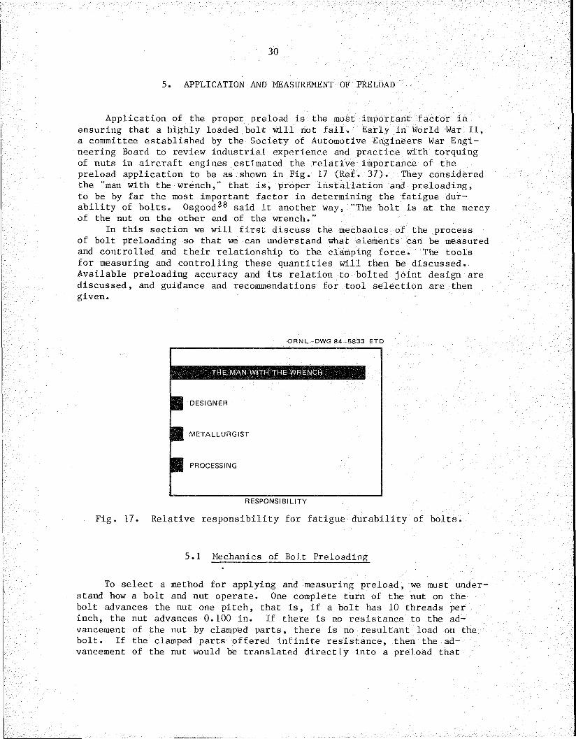
Application of the proper preload is the most important factor in ensuring that a highly loaded bolt will not fail. Early in World War II, a committee established by the Society of Automotive Engineers War Engineering Board to review industrial experience and practice with torquing of nuts in aircraft engines estimated the relative importance of the preload application to be as shown in Fig. 17 (Ref. 37). They considered the "man with the wrench,” that is, proper installation and preloading, to be by far the most important factor in determining the fatigue durability of bolts. Osgood^8 said it another way, "The bolt is at the mercy of the nut on the other end of the wrench."
In this section we wi11 first discuss the mechanics of the process of bolt preloading so that we can understand what elements can be measured and controlled and their relationship to the clamping force. The tools for measuring and controlling these quantities will then be discussed. Available preloading accuracy and its relation to bolted joint design are discussed, and guidance and recommendations for tool selection are then given.
ORNL-DWG 84-5833 ETD
THE MAIM WITH THE WRENCH
DESIGNER
METALLURGIST
PROCESSING
RESPONSIBILITY
Fig. 17. Relative responsibility for fatigue durability of bolts.
5.1 Mechanics of Bolt Preloading
To select a method for applying and measuring preload, we must understand how a bolt and nut operate. One complete turn of the nut on the bolt advances the nut one pitch, that is, if a bolt has 10 threads per inch, the nut advances 0.100 in. If there is no resistance to the advancement of the nut by clamped parts, there is no resultant load on the bolt. If the clamped parts offered infinite resistance, then the advancement of the nut would be translated directly into a preload that
31
would be determined by the stiffness of the bolt. In a real joint, the stiffness of the clamped parts is always less than infinite so that part of the deformation imposed by the advancement of the nut goes into a deformation of the clamped parts. In other words, the bolt elongates less than one pitch, and the clamped parts are compressed somewhat. The relative amount of these two quantities depends only on the relative stiffness of the bolt and clamped parts.
In essence, a bolt is an application of the inclined plane. As the nut is turned it advances up the threads. In the absence of friction, there would be a unique relation between the torque applied to the nut and the preload induced in the bolt. If a torque T was applied to a frictionless nut with a pitch n, the preload P induced in the bolt would be given by
P 2ttT' ' 0n (22)
In reality, friction between the threads of the nut and the bolt and between the nut and the clamped parts must be overcome by the applied torque. The required torque according to Bickford22, based on work by Motosh,39 is given by
T Vt ,cos B ^nrn (23)
where is the coefficient of friction between the threads of the nut and bolt, r is the effective contact radius of the threads, $ is the half angle of the threads [30° for Unified National (UN) or International Standards Organization (ISO) threads], is the coefficient of friction between the nut and the clamped parts, and r^ is the effective radius of contact between the nut and the clamped parts. This equation may be rearranged to give preload explicitly
P T11 + ^ ^ 4--y— + ---- r + p r2n cos 3 n n
(24)
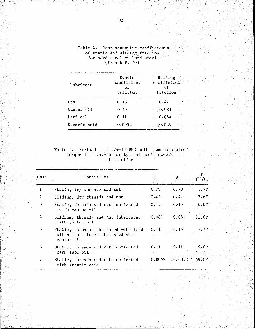
Representative values of the coefficient of friction for hard steel on hard steel are given in Table 4 for both static and sliding conditions. The lubricant used has a large effect on the coefficient of friction. In general, the friction coefficient is reduced once motion is initiated.The effect of various coefficients of friction on the relation between torque and preload is given in Table 5. The dimension of a 3/4—10 UNC nut was used in Eq. (24) to obtain the preload in a typical bolt for different coefficients of friction. For dry threads and nut face under static conditions, the preload in pounds is only 1.4 times the torque in inch-pounds. For threads and nut face lubricated with stearic acid and
32
Table 4• Representative coefficients of static and sliding friction for hard steel on hard steel
(from Ref. 40)
Static SlidingLubricant coefficient
ofcoefficient
offriction friction
Dry 0.78 0.42Castor oil 0.15 0.081Lard oil 0.11 0.084Stearic acid 0.0052 0.029
Table 5. Preload in a 3/4—10 UNC bolt from an applied torque T In in.-lb for typical coefficients
of friction
Case Conditions wt »nP
(lb)
1 Static, dry threads and nut 0.78 0.78 1.4T2 Sliding, dry threads and nut 0.42 0.42 2.6T3 Static, threads and nut lubricated
with castor oil0.15 0.15 6.8T
4 Sliding, threads and nut lubricated with castor oil
0.081 0.081 11.6T
5 Static, threads lubricated with lard oil and nut face lubricated with castor oil
0.11 0.15 7.7T
6 Static, threads and nut lubricated with lard oil
0.11 0.11 9.0T
7 Static, threads and nut lubricated with stearic acid
0.0052 0.0052 49.0T

33
still under static conditions, the preload is 49.0 T. If friction were zero, the preload would be 62.8 T. These are extreme cases.
Recommendations1+1 for assembly torque indicate that the preload would be expected to be ~6.7 T for a nonplated 3/4—10 UNC steel bolt. This is very close to Case 3 in Table 5, which indicates that the coefficient of friction in a typical bolt is ~0.15. Case 4 is for the same lubricant as Case 3 but is for sliding conditions instead of static conditions. The preload for Case 4 is 70% higher than for Case 3. If the bolt were tightened by hand, the loading would be very nearly static corresponding to Case 3. Tightening with a machine such as a hydraulic wrench would correspond to Case 4 because the nut would be run on up to the prescribed torque in a continuous motion and the preload would therefore be 70% higher than if tightened by hand. These examples and further study of Table 3 show why torque is an inaccurate measure of preload except under very carefully controlled conditions. Variation in clamping load of up to ±30% for the same torque has been determined from tests2^ > 37 >42 an(j iS generally accepted1*3—1+5 to be the best accuracy that can be achieved without extreme care. Because of the large variability of the torque-to- tension relationship for seemingly similar bolts and conditions, recognition of torque control methods was withdrawn in the August 14, 1980, edition of the AISC Specifioation for Structural Joints Using ASTM A325 or A490 Bolts.1
Bolts are designed to be assembled by turning the nut. In most instances , sufficient torque is applied to the nut to produce the requiredpreload. Note that this results in a torsional stress in the bolt in addition to the axial load. This can result in a lower apparent yield strength.4+6 An alternative approach is to stretch the bolt and then runthe nut down until it contacts the clamped parts. The bolt can bestretched by a hydraulic tensioner1*1* that applies a known load to the bolt or by heating1*7 the bolt so that it increases in length as a result of thermal expansion.
5.2 Quantities Measured to Assess Preload
Since bolts are usually torqued to apply preload and it is easily measured, torque is the quantity traditionally measured to assess preload . However, because of the role of friction as previously discussed, the value of applied torque does not relate very accurately to the bolt preload.
A torque wrench is only one of several ways of controlling the applied torque. Nut runners, impact wrenches, hydraulic wrenches, twist- off nuts, and twist-off bolts are other torque control methods. Nut runners, impact wrenches, and hydraulic wrenches may all be set to apply a specified torque. Good practice requires frequent calibration. Twist- off nuts and twist-off bolts both twist off when the required torque is applied. The twist-off bolt requires a special tool for assembly; however, it offers the advantage of installation from one side.
The next quantity that one might choose to relate to preload is the nut rotation. However, several factors keep nut rotation from relating accurately to preload. The relative stiffnesses of the bolt and clamped
34
parts affect the relationship between nut rotation and preload. Furthermore , the actual load-rotation curve is very nonlinear and nonrepeatable when the preloading first starts because of such things as the initial seating of the clamped parts and bolt. Consequently, it is difficult to determine where to start measuring the amount of nut rotation.
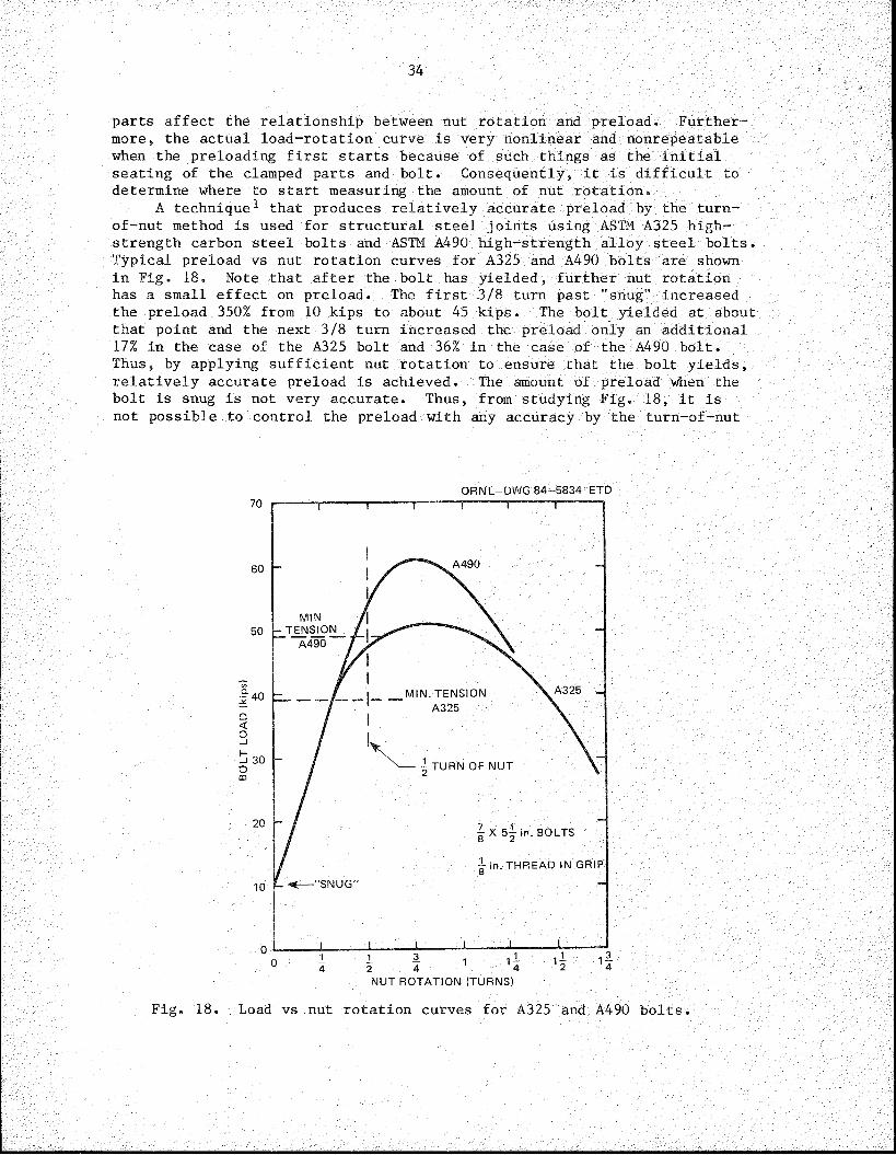
A technique1 that produces relatively accurate preload by the turn- of-nut method is used for structural steel joints using ASTM A325 high- strength carbon steel bolts and ASTM A490 high-strength alloy steel bolts. Typical preload vs nut rotation curves for A325 and A490 bolts are shown in Fig. 18. Note that after the bolt has yielded, further nut rotation has a small effect on preload. The first 3/8 turn past "snug" increased the preload 350% from 10 kips to about 45 kips. The bolt yielded at about that point and the next 3/8 turn increased the preload only an additional 17% in the case of the A325 bolt and 36% in the case of the A490 bolt. Thus, by applying sufficient nut rotation to ensure that the bolt yields, relatively accurate preload is achieved. The amount of preload when the bolt is snug is not very accurate. Thus, from studying Fig. 18, it is not possible to control the preload with any accuracy by the turn-of-nut
ORNL-DWG 84-5834 ETD
A490
A325 „MIN. TENSION A325
-i 30 Iturn OF NUT
X 5^ in. BOLTS
1 in. THREAD IN GRIP"SNUG"
NUT ROTATION (TURNS)
Fig. 18. Load vs nut rotation curves for A325 and A490 bolts.

35
method without yielding the bolt. In cases where stress corrosion cracking is a problem, the maximum allowable preload must usually be below the yield point to avoid stress corrosion cracking.
Special control systems 22,48~5Q have been developed that monitor both torque and nut rotation and yield much better preload control than either method alone. Such systems have been designed primarily for assembly line use in the automotive and aircraft industries using relatively low-torque production tools, such as nut runners. Although the techniques are best suited to high production assembly line operations because of the sophisticated instrumentation required, portable systems are available that would be amenable to use in nuclear reactor construction. These techniques can detect problems such as cross-threading or bottoming of a bolt in a blind hole. They can also provide a permanent record of the tightening process for quality control and for future reference.
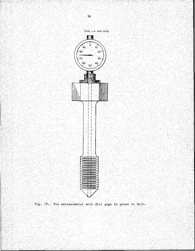
The amount of stretch of the bolt is a more direct measure of the bolt preload. A micrometer caliper may be used to measure the length of the bolt before and after tightening if both ends are accessible and there is room for the micrometer caliper.23,47 Otherwise, a hole can be drilled through the center, and a pin can be inserted and welded at one end. A micrometer depth gage may then be used to measure the stretch. Alternatively, a dial gage may be used to measure the stretch as in the pin extensometer-sensor shown in Fig. 19 (Ref. 51).
Several devices have been developed that use ultrasonics to measure the bolt stretch.22,52-57 Commercial ultrasonic equipment designed specifically for measuring bolt stretch is marketed by at least two companies . *
Measurement of bolt stretch is an accurate indicator of preload provided that the actual stretch is measured and the measurement is made with sufficient precision. One must be careful to ensure that the ends of the bolt are perfectly flat or that the length measurements before and after preloading are made at exactly the same location.
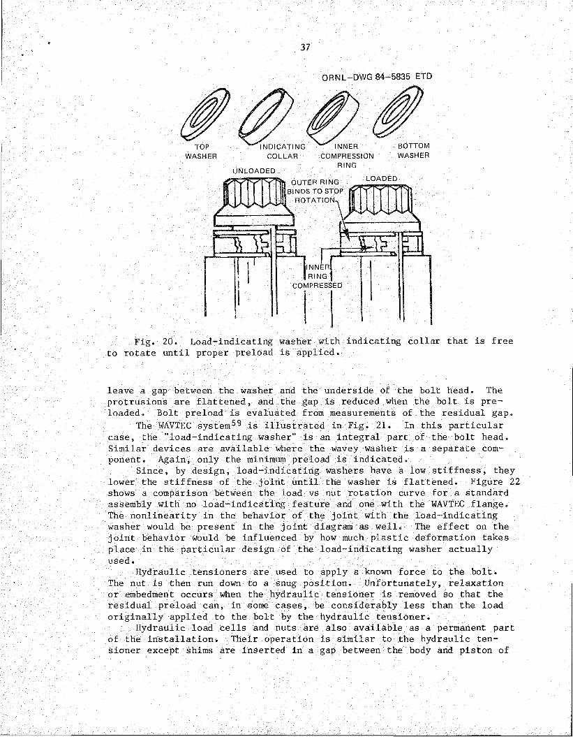
More direct measurement of preload, including strain-gaged bolts, strain-gaged force washers, load-indicating washers, and hydraulic tensioning devices, can be used to measure preload. Strain-gaged bolts or strain-gaged force washers can provide extremely accurate preload control but are relatively expensive. At least two companiest market strain-gaged bolts and studs. One concept of the load-indicating washer2^,1+1+ is shown in Fig 20. Initially, the indicating collar is slightly shorter than the inner compression ring, so it is free to turn. As the nut is tightened, the inner compression ring is compressed until, at the designated preload, the indicating collar can no longer turn. Such a load-indicating washer ensures that the minimum preload is applied but does not indicate the maximum preload applied.
Other load-indicating washers include patented devices such as the Coronet load indicator^8 and the WAVTEC system.89 The Coronet load indicator is a hardened washer with a series of protrusions on one face that
Raymond Engineering, Inc., Power-Dyne Division, Middletown CT 06457; Stresstel Corp., Scotts Valley, CA 95066.
Strainsert Company, West Conshohocken, PA 19428; Eaton Corp., Electronic Instrumentation Division, Los Angeles, CA 90066.
36
ORNL—LR—DWG 59792
y
i i
Fig. 19. Pin extensometer with dial gage in place on bolt.
911898^495
37
ORNL-DWG 84-5835 ETD
TOPWASHER
BOTTOMWASHER
LOADEDOUTER RING BINDS TO STOP
ROTATION-.
JlNNER 1 RING
COMPRESSED
Fig. 20. Load-indicating washer with indicating collar that is free to rotate until proper preload is applied.
leave a gap between the washer and the underside of the bolt head. The protrusions are flattened, and the gap is reduced when the bolt is pre- loaded. Bolt preload is evaluated from measurements of the residual gap.
The WAVTEC system59 is illustrated in Fig. 21. In this particular case, the "load-indicating washer” is an integral part of the bolt head. Similar devices are available where the wavey washer is a separate component. Again, only the minimum preload is indicated.
Since, by design, load-indicating washers have a low stiffness, they lower the stiffness of the joint until the washer is flattened. Figure 22 shows a comparison between the load vs nut rotation curve for a standard assembly with no load-indicating feature and one with the WAVTEC flange. The nonlinearity in the behavior of the joint with the load-indicating washer would be present in the joint diagram as well. The effect on the j oint behavior would be influenced by how much plastic deformation takes place in the particular design of the load-indicating washer actually used.
Hydraulic tensioners are used to apply a known force to the bolt.The nut is then run down to a snug position. Unfortunately, relaxation or embedment occurs when the hydraulic tensioner is removed so that the residual preload can, in some cases, be considerably less than the load originally applied to the bolt by the hydraulic tensioner.
Hydraulic load cells and nuts are also available as a permanent part of the installation. Their operation is similar to the hydraulic tensioner except shims are inserted in a gap between the body and piston of
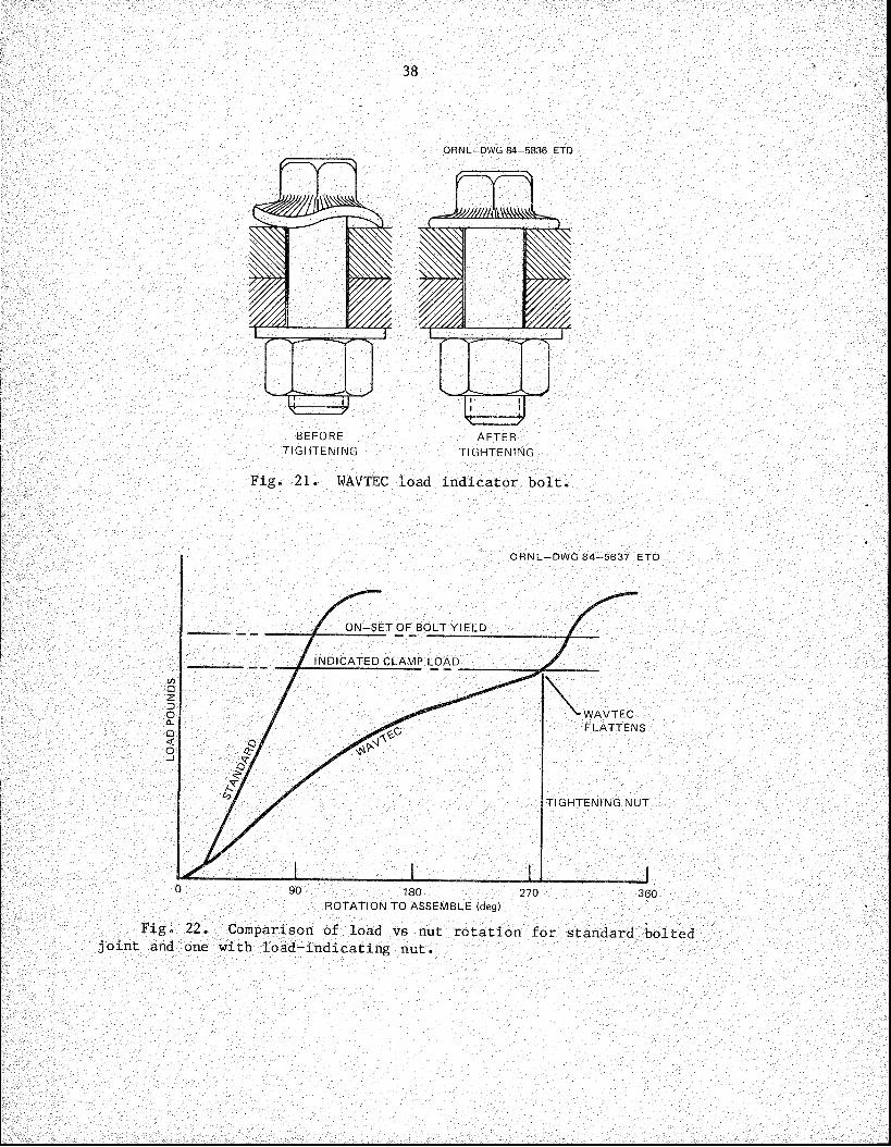
38
ORNL-DWG 84-5836 ETD
BEFORETIGHTENING
Fig. 21. WAVTEC load indicator bolt.
ORNL-DWG 84-5837 ETD
ON-SET OF BOLT YIELD
INDICATED CLAMP LOAD
WAVTECFLATTENS
TIGHTENING NUT
180ROTATION TO ASSEMBLE (deg)
Fig. 22. Comparison of load vs nut rotation for standard bolted joint and one with load-indicating nut.

39
the hydraulic device to carry the load when the hydraulic pressure is released and the pumping equipment is removed.
5.3 Accuracy of the Preloading Methods
It is clear that several methods are available for tightening bolts. From these methods, one that will produce preload with the required accuracy must be selected. Accuracy of the applied preload depends on three factors: (1) tool accuracy, (2) operator accuracy, and (3) control accuracy. Tool accuracy is the accuracy of the tool in measuring the entity that it measures directly. Operator accuracy relates to the additional error introduced by the operator as a result of such things as lack of skill, poor working conditions (e.g., hard to reach nut locations and poor lighting), and carelessness. Control accuracy relates to the accuracy with which the preload is controlled by the quantity actually being measured . As an example, consider a bolt that is preloaded using a bar torque wrench. The torque wrench itself may have an accuracy ±5% of full scale. If the torque required is only one-haIf of full scale, then the tool accuracy is reduced to ±10%. Even if the torque wrench were perfect, some error would be introduced by the operator. Under field conditions, an operator error of ±10% might easily occur. As previously discussed, the variability of friction results in the torque not being uniquely related to preload. A variation in preload for a given torque of ±30% is not unusual. When each of these three sources of inaccuracy are combined, the total accuracy is
± J 102 + 102 + 302 = ±33% (25)
Reliable and consistent comparisons of tool accuracy, as well as control accuracy and operator accuracy, are difficult to make because of the many variables that affect the comparisons. Estimates of tool accuracy and control accuracy from Machine Design Reference Issue on Fastening and Joining1*^ are given in Tables 6 and 7. Note that the tool accuracies are given as a percentage of full scale. Therefore, the error obtained on a particular joint may be considerably greater than the tabulated value if the maximum torque is only a fraction of full scale. Note also that digital torque wrenches have typical accuracies of ±0.25 to 1% of full scale. However, Table 7 shows that torque control can at best result in a ±15% variation, so that even with a digital torque wrench and zero operator error, the best possible accuracy of preload would be
/(0.25)2 + (15)2 + (0)2 - ±15% . (26)
Thus, control accuracy is the most important element in preload accuracy in this case. Greatly improved control accuracy can be obtained by torquing past yield or by direct measurement of bolt stretch.
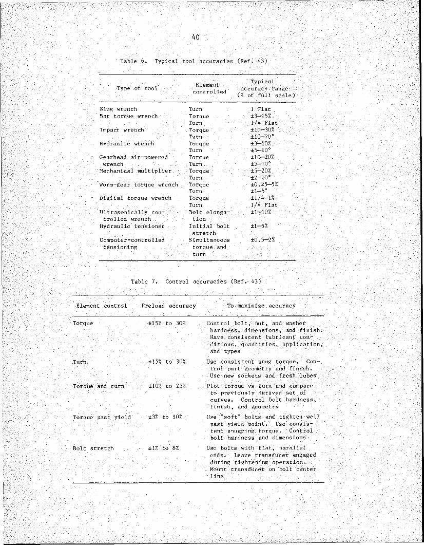
40
Table 6. Typical tool accuracies (Ref. 43)
Type of tool Elementcontrolled
Typicalaccuracy range
(% of full scale)Slug wrench Turn 1 FlatBar torque wrench Torque ±3-15%
Turn 1/4 FlatImpact wrench Torque ±10-30%
Turn ±10-20°Hydraulic wrench Torque ±3-10%
Turn ±5-10°Gearhead air-powered Torque ±10-20%wrench Turn ±5—10°
Mechanical multiplier Torque ±5-20%Turn ±2-10°
Worm-gear torque wrench Torque ±0.25-5%Turn ±1-5°
Digital torque wrench Torque ±1/4-1%Turn 1/4 Flat
Ultrasonically con- Bolt elonga- ±1-10%trolled wrench tion
Hydraulic tensioner Initial bolt stretch
±1-5%
Computer-controlled Simultaneous ±0.5-2%tensioning torque and
turn
Table 7. Control accuracies (Ref. 43)
Element control Preload accuracy To maximize accuracy
Torque ±15% to 30%
Turn ±15% to 30%
Torque and turn ±10% to 25%
Torque past yield ±3% to 10%
Bolt stretch ±1% to 8%
Control bolt, nut, and washer hardness, dimensions, and finish. Have consistent lubricant conditions, quantities, application, and types
Use consistent snug torque. Control part geometry and finish.Use new sockets and fresh lubesPlot torque vs turn and compare to previously derived set of curves. Control bolt hardness, finish, and geometry
Use "soft" bolts and tighten well past yield point. Use consistent snugging torque. Control bolt hardness and dimensions
Use bolts with flat, parallel ends. Leave transducer engaged during tightening operation.Mount transducer on bolt center line
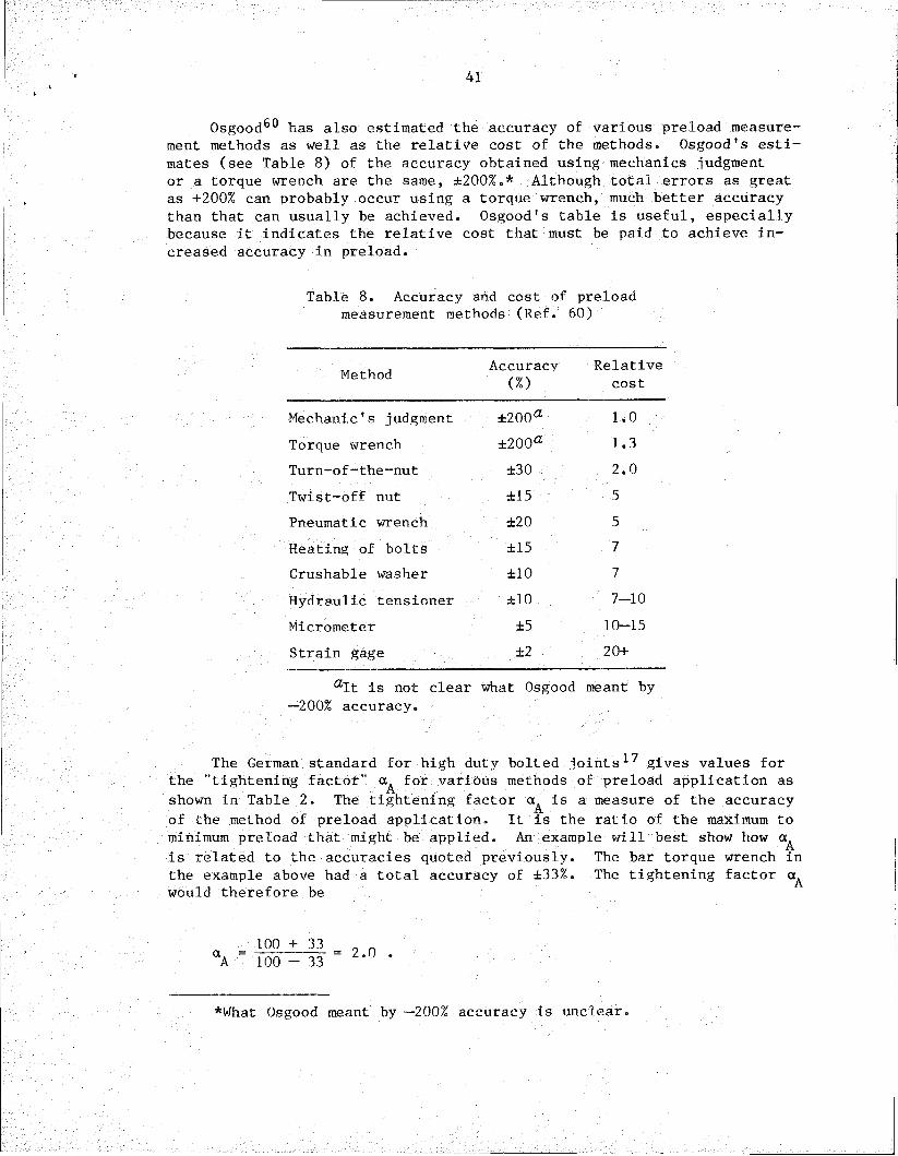
41
Osgood6® has also estimated the accuracy of various preload measurement methods as well as the relative cost of the methods. Osgood's estimates (see Table 8) of the accuracy obtained using mechanics judgment or a torque wrench are the same, ±200%.* Although total errors as great as +200% can probably occur using a torque wrench, much better accuracy than that can usually be achieved. Osgood's table is useful, especially because it indicates the relative cost that must be paid to achieve increased accuracy in preload.
Table 8. Accuracy and cost of preload measurement methods (Ref. 60)
Method Accuracy(%)
Relativecost
Mechanic's judgment ±200a 1.0Torque wrench ±200a 1.3Turn-of-the-nut ±30 2.0Twist-off nut ±15 5Pneumatic wrench ±20 5Heating of bolts ±15 7Crushable washer ±10 7Hydraulic tensioner ±10 7-10Micrometer ±5 10-15Strain gage ±2 20+
aIt is not clear what Osgood meant by—200% accuracy.
The German standard for high duty bolted joints17 gives values for the "tightening factor" for various methods of preload application as shown in Table 2. The tightening factor is a measure of the accuracy of the method of preload application. It is the ratio of the maximum to minimum preload that might be applied. An example will best show how is related to the accuracies quoted previously. The bar torque wrench in the example above had a total accuracy of ±33%. The tightening factor would therefore be
= 100 + 33 aA 100 - 33 2.0 .
*What Osgood meant by —200% accuracy is unclear
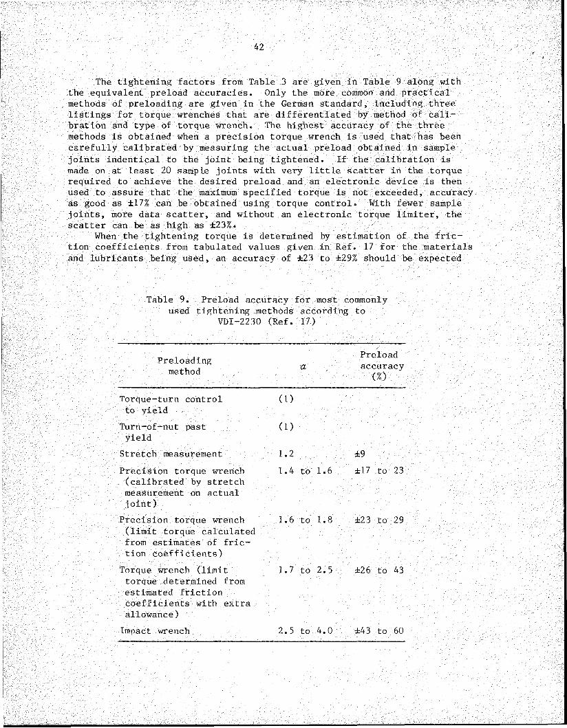
42
The tightening factors from Table 3 are given in Table 9 along with the equivalent preload accuracies. Only the more common and practical methods of preloading are given in the German standard, including three listings for torque wrenches that are differentiated by method of calibration and type of torque wrench. The highest accuracy of the three methods is obtained when a precision torque wrench is used that has been carefully calibrated by measuring the actual preload obtained in sample joints indentical to the joint being tightened. If the calibration is made on at least 20 sample joints with very little scatter in the torque required to achieve the desired preload and an electronic device is then used to assure that the maximum specified torque is not exceeded, accuracy as good as ±17% can be obtained using torque control• With fewer sample joints, more data scatter, and without an electronic torque limiter, the scatter can be as high as ±23%.
When the tightening torque is determined by estimation of the friction coefficients from tabulated values given in Ref. 17 for the materials and lubricants being used, an accuracy of ±23 to ±29% should be expected
Table 9. Preload accuracy for most commonly used tightening methods according to
VDI-2230 (Ref. 17)
Preloadingmethod
Preloada accuracy
(%)Torque-turn control to yield
Turn-of-nut past yield
Stretch measurement
(1)
(1)1.2 ±9
Precision torque wrench (calibrated by stretch measurement on actual joint)
Precision torque wrench (limit torque calculated from estimates of friction coefficients)
Torque wrench (limit torque determined from estimated friction coefficients with extra allowance)
Impact wrench
1.4 to 1.6 ±17 to 23
1.6 to 1.8 ±23 to 29
1.7 to 2.5 ±26 to 43
2.5 to 4.0 ±43 to 60

43
if precision torque wrenches are employed. Use of less precise torque wrenches and an extra allowance on the specified torque determined from the estimated friction coefficients will produce an accuracy of ±26 to ±43%.
With any of the procedures requiring the use of a torque wrench, better relative accuracy is achieved when the clamped parts are relatively stiff; the accuracy is not so good when the clamped parts are not relatively stiff or when fine threads are used. The preload accuracy using the first two methods in Table 9 is almost completely determined by the variability of the yield strength. The bolts are therefore sized on the basis of the preload obtained from Eq. (22), assuming the minimum yield strength instead of using Eq. (21). Hence, the tightening factor is not used when the torque-turn control to yield or the turn-of-nut past yield methods are used. The values in parentheses serve to compare the tightening precision with that obtained by the other tightening methods. Both methods are considered to be relatively accurate.
Determination of preload by measurement of the length change of the bolt gives an accuracy of ±9%. Finally, the use of an impact wrench produces a preload accuracy of from ±43 to ±60%.
5.4 Code Requirements for Selection of Preloading Method
Like most engineering decisions, the selection of preloading method must be a compromise that best meets the requirements of a particular situation. The primary consideration in the case of bolting for joints that fall under the jurisdiction of a Code is that it must meet the Code requirements. Those requirements for component supports are given by paragraph NF-4724 of Ref. 2, which states "Preloading shall be monitored by the turn of nut method, by properly calibrated wrenches, by load indicating washers, or by direct extension indicators."
Requirements of methods for determining bolting preload are not given for other nuclear components covered by Section III of the ASMS Boiler and Pressure Vessel Code. However, mandatory "Appendix XII, Design Considerations for Bolted Flanged Connectionsdoes give the following guidance in paragraph XII-I100(m)
(m) Another very important item in bolting design is the question of whether the necessary bolt stress is actually realized and what special means of tightening, if any, must be employed. Most joints are tightened manually by ordinary wrenching and it is advantageous to have designs that require no more than this. Some pitfalls must be avoided, however.The probable bolt stress developed manually, when using standard wrenches, is:
S = 45,000/^d"
where S is the bolt stress and d is the nominal diameter of the bolt. It can be seen that smaller bolts will have excessive stress unless judgment is exercised in pulling up on

44
them. On the other hand, it will be impossible to develop the desired stress in very large bolts by ordinary hand wrenching. Impact wrenches may prove serviceable, but, if not, resort may be had to such methods as preheating the bolt or using hydraulically powered bolt tensioners. With some of these methods, control of the bolt stress is possible by means inherent in the procedure, especially if effective thread lubricants are employed, but in all cases the bolt stress can be regulated within reasonable tolerances by measuring the bolt elongation with suitable extensometer equipment. Ordinarily, simple wrenching without verification of the actual bolt stress meets all practical needs, and measured control of the stress is employed only when there is some special or important reason for doing so.
Note that this paragraph emphasizes the use of manual wrenching for tightening bolts in flanged connections. As noted above, hand tightening is very imprecise. Therefore, the question of why this guidance remains in the Code is raised. The apparent answer is that reasonable success has been achieved using this guidance. How can this be? With flanged joints bolt preload is not the problem one might expect. If the joint is not tightened enough it will leak, and the bolts will be tightened until leakage no longer occurs. Thus, a sufficient level of minimum preload will be applied. The other extreme is taken care of because the bolt will break during installation if too much torque is applied. Because of the effects of yielding, relaxation, or embedment and the torsional stress during torquing, there is enough of a decrease in bolt stress when the wrench is removed that bolt failure is unlikely if it does not occur during wrenching. However, if the material and environment are such that stress-corrosion cracking is a problem, tighter control on maximum-bolt preload must be exercised to prevent bolt failure in service.
Reference 5 gives requirements for steel safety-related structures and structural elements for nuclear facilities not covered by the ASME Boiler and Pressure Vessel Code. Paragraph Ql.23.8 of Ref. 5 specifies that A325 and A490 bolts be tightened to not less than 70% of their specified minimum tensile strength by the turn-of-nut method or by the use of direct tension indicators. This is in compliance with the August 14, 1980, version of the AISC Specification for Structural Joints Using ASTM AS25 and A490 Bolts.^ Earlier versions allowed use of calibrated wrenches. Note that the requirements of ASME Code Subsection NF2 are similar to the earlier versions of the AISC bolt specification, except that the ASME Code specifies use of "direct extension indicators" or "load-indicating washers,” whereas the AISC bolt specification calls for use of a "direct tension indicator." Neither explains what is meant by "direct extension indicators" or "direct tension indicators." The background document^ for the AISC bolt specification does say that direct tension indicators depend on strain or displacement control instead of torque control. It also cites swedge bolts, load-indicating washers, and load-indicating bolts as examples of commercially available direct tension indicators. It is not clear what the ASME Code Subsection NF defines as direct extension indicators. Perhaps they mean the same as direct tension

45
indicators, but they may be referring only to methods that measure the change in length of the bolt.
Paragraph CQ 1.23.8 of the commentary to Ref. 5 states that a calibrated wrench may be used for bolts other than A325 and A490 bolts.
5.5 Industry Bolting Practice
Another consideration in the selection of a preloading method for bolting is the current practice in the nuclear industry. The EPRI recently funded a surveyof the utility industry methods in torquing, tensioning, and bolting. It was found that the tools being used ranged from slug wrenches, which are tightened by striking with a sledge hammer, to hydraulic multistud tensioners. Slug wrenches, impact wrenches, and mechanical multipliers are usually used in the secondary system. They found very little application of torque wrenches and bolting specifications in the secondary systems.
Rigid torque specifications are applied in the primary systems. Manual torque wrenches were found to be used most commonly, with the beam and click varieties being the most popular. Torque multipliers are used for obtaining high torques. Hydraulic tensioners are always used for the head bolts of the reactor pressure vessel. It was also noted that hydraulic wrenches were being used more frequently.
5.6 Recommendations for Preloading of Bolted Connections
When bolts with reasonable ductility* are used and there is no propensity for stress corrosion cracking, it is recommended that the requirements of the Specification for Structural Joints Using ASTM A3 26 or A490 Bolts1 should be followed. That is, either the turn-of-nut method or a direct tension indicator should be used that has been demonstrated to produce a minimum fastener tension equal to 70% of the specified minimum tensile strength of the bolts. This will produce a preload in the bolts of no less than 70% of the specified minimum tensile strength. The highest preload will be on the order of 5 to 15% below the maximum tensile strength of the bolts. This upper bound is a result of the fact that the bolt will break immediately if its tensile strength is exceeded during installation. Relaxation or embedment immediately reduces the initial preload by 2 to 11%. The torsional stress induced during the torquing operation reduces the apparent yield strength of the bolt. The apparent yield strength increases again when the torsional stress is reduced.t Therefore, the resultant preload accuracy of something on the order of ±10 or 15% is as good as can be achieved without resorting to extreme bolting
*The criterion of reasonable ductility means that the bolt elongation at failure is at least as great as that of an A490 bolt of the same dimensions.
tDetailed treatment of the interaction of the torsional and axial stress in bolts is given in Ref. 17.

46
procedures. Furthermore, the highest practical preload is achieved. This makes detailed analysis of every joint unnecessary. Finally, use of certain direct tension indicators, such as load-indicating washers, simplifies inspection of the bolted joints as will be discussed in the next section.
In some instances it will not be possible to apply the procedures outlined above. A prime example is when the bolt is subject to stress corrosion cracking. A careful and complete joint analysis, which includes consideration of preload relaxation, is then required to establish the minimum allowable preload. Data for determining the maximum permissible preload that will not result in stress corrosion cracking must be obtained or it must be conservatively estimated. Thus, a preloading method must be selected which will provide sufficient accuracy to ensure that the actual preload is within the required range. Methods such as the "turn-of-nut" or "torque-turn control to yield" cannot be used because the maximum preload is only controlled by the strength of the bolt when such techniques are used. Appropriate methods for use, in order of increasing accuracy, are torque control, hydraulic tensioner, length measurement, and strain gages. It is recommended that every effort be made to design the joint so that the permissible preload range is as large as possible. This makes it possible for the less expensive and more widely used preloading techniques to be used. It must be remembered that workers are more apt to make mistakes when they are using techniques they do not use often. Furthermore, delays may result because the correct tools are not at hand.

47
6. CONCRETE ANCHOR BOLTS
Expansion anchor bolts are used to attach component and pipe supports to structural concrete. Structural failures of piping supports for safety equipment, found in 1978 during an in-service inspection at Millstone Unit 1, resulted in further inspections of undamaged supports. These inspections revealed that a large percentage of the concrete anchor bolts were not tightened properly. As a result, the NRC issued IE Bulletin No. 79-02 (Ref. 63), followed by a revision^** and supplement6^ to the original IE Bulletin No. 79-02 requiring that anchor bolts for pipe support base plates be reexamined. This IE Bulletin also drew attention to the increased bolt load resulting from prying action that can result from support plate flexibility and the possibility of deleterious effects of cyclic loading on the holding power of concrete anchor bolts.
Shortly after IE Bulletin No. 79-02 was issued, a consortium of 14 utilities commissioned Teledyne Engineering services to do an extensive testing program on anchor bolts.66 > 67 These studies showed that the strength values given in the manufacturers' catalogs were correct if the manufacturers' installation instructions were carefully adhered to. Shear-tension interaction tests showed that a linear shear-tension interaction formula was too conservative. A small amount of shear increased the tensile pullout load. Dynamic cyclic tests showed that cyclic loading within allowable load levels did not adversely affect the strength of the anchor bolts. It was found that bolt preload was not necessary to give good cyclic performance of the concrete anchor once the anchor was properly set.
Considerable work on concrete anchor bolts has also been done at the Hanford Engineering Development Laboratory,68,69 where existing concrete anchor bolt test data were surveyed. Also additional tests were performed to determine the effect of preload on anchor bolt performance under dynamic loading. It was found that although the ultimate strength was not significantly impaired by cyclic dynamic loading, the stiffness was lower than for static loading. The residual preload did not significantly affect anchor load-displacement characteristics under dynamic loading unless the preload was <50% of the full installation preload. The stiffness was slightly less when zero residual preload existed. This decrease in stiffness can result in an increase in prying action in the baseplate. Because of the possibility of causing the anchor to slip if the installation torque were reapplied during in-service inspections, HEDL recommended that anchors with reduced preload not be retorqued.
It appears that the principal problems with anchor bolts are those of correct design and proper installation. If the factors of safety on ultimate load capacity of four for wedge- and sleeve-type anchor bolts and five for shell-type anchor bolts recommended by IE Bulletin No. 79-02 are applied, the spacing requirements of ACI-349 (Ref. 70) are met, and the proper installation procedures (including minimum embedment depth) are followed, anchor bolts should perform satisfactorily. However, it is necessary that proper attention be given to the effects of prying action.
The flexibility of the baseplate must be considered when determining the effect of prying action on the working load to which the bolt will be subjected. The procedure for considering prying action given in

48#
VDI-2230 (Ref. 17) is not applicable for flexible plates. Finite-element analysis71 or the closed-form approach using the elastic solutions to the beam on elastic foundation problem presented by Hou72 may be used to correctly determine the bolt loading. The reduced stiffness of the anchor bolt under dynamic loading must be considered in this analysis also. Bolt preload should then be set high enough to prevent lift-off.

49
7. REACTOR VESSEL INTERNALS FASTENERS
This study is aimed primarily at bolted joints in component supports; however» because problems have occurred in the reactor vessel internal fasteners,6 they deserve some attention here. Generally, the guidance given in this report for component support bolting can be applied equally well to reactor vessel internal fasteners, since they are both ungasketed joints. The only additional guidance is to stress the importance of material selection, fastener design, and fastener manufacture since special fasteners are often used in reactor vessel internals. Careful attention must be given to determination of the loads imposed on the joint including hydraulic loading, thermal loading, and cyclic loading which is due to such phenomena as vortex shedding and thermal mixing. Also, water chemistry may be of particular importance. Material compatibility with regard to potential galvanic action that may increase the propensity for stress corrosion cracking must be considered.
Finally, because of the difficulty of inspection and repair, along with the vibrations that are often present, special steps should be taken to ensure that the nuts or bolts do not back off and become loose during service. Many techniques and devices have been developed to prevent vibrational loosening. Table 10 shows the relative performance of some of the available methods of preventing vibrational loosening.Only the liquid threadlockers and preapplied threadlockers were rated as excellent in their locking performance. However, these materials generally lose strength at temperatures above 300°F (149°C), although some maintain good strength to temperatures as high as 450°F (230°C). Potential chemical incompatibility problems, as well as the temperature limitations, rule out their use in reactor internals. The only other device in Table 10 that received a good rating for locking performance was the serrated head. However, preload loss due to embedment may be excessive with such fasteners. They may also cause failure of the clamped parts because the digging into the clamped parts that occurs may initiate cracks.
Consideration of special locking devices,71* such as the one shown in Fig. 23, is often warranted for reactor vessel internal fasteners.Such devices should be designed to minimize the possibility of loose parts in the event of a failure of the fastener or locking devices.
ASME Code Section III, Division 1, Subsection NG75 provides rules for core support structures. These rules apply to other internal structures only when so stipulated by the Certificate Holder. Stress limits for threaded structural fasteners are given in Subarticle 3230. The average stress in the bolt (primary plus secondary membrane stress including stress from preload) is restricted to 90% of the minimum yield strength or two-thirds of the minimum ultimate strength at the service temperature. The maximum membrane stress intensity during preloading is restricted to 1.08 times the minimum yield strength or 0.80 times the minimum ultimate strength at the installation temperature. No minimum limits are placed on the preload.
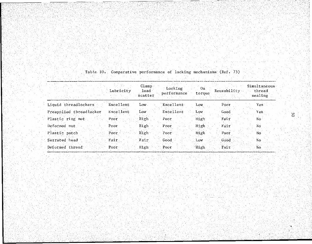
Table 10. Comparative performance of locking mechanisms (Ref. 73)
LubricityClampload
scatterLocking
performanceOn
torque ReusabilitySimultaneous
threadsealing
Liquid threadlockers Excellent Low Excellent Low Poor YesPreapplied threadlocker Excellent Low Excellent Low Good YesPlastic ring nut Poor High Poor High Fair NoDeformed nut Poor High Poor High Fair NoPlastic patch Poor High Poor High Poor NoSerrated head Fair Fair Good Low Good NoDeformed thread Poor High Poor High Fair No
%
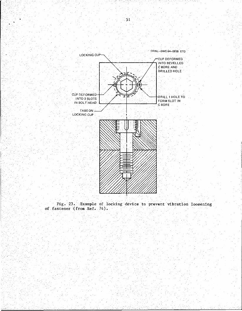
51
ORIML-DWG 84-5838 ETDLOCKING CUP
CUP DEFORMED INTO BEVELLED C BORE AND DRILLED HOLE
CUP DEFORMED INTO 3 SLOTS
IN BOLT HEAD
•DRILL 1 HOLE TO FORM SLOT IN C BORE
TABS ON LOCKING CUP
Fig. 23. Example of locking device to prevent vibration loosening of fastener (from Ref. 74).

52
8. PRESSURE BOUNDARY BOLTING
The main concern of this report is bolted joints in component supports. Such joints are nongasketed and are nonpressure-containing. Bolted pressure-containing joints are generally flanged with a relatively soft gasket material (between the flanges) that is deformed into the irregularities of the mating surfaces when the bolting preload is applied. Appendix XI of Section III, Division 1 of the ASME Boiler and Pressure Vessel Code1^ provides rules for the design of bolted flange connections for Class 2 and 3 components and Class MC vessels. Bolt preload is required to be high enough to overcome the hydrostatic end force and still retain enough compression on the gasket to prevent leakage. The bolt preload must also be high enough to seat the gasket properly by applying a minimum initial load under atmospheric temperature conditions without the presence of internal pressure. The required seating load depends on the gasket material and the effective gasket area to be seated. Factors (m and y) are given in Appendix XI which allow determination of the required bolt loads. These factors — first introduced into the Code in the 1930s — have remained in the Code relatively unchanged.
Unfortunately, the calculated bolt preload does not always produce a joint that is leaktight, and additional unknown preload is often applied until a satisfactory seal is obtained.
A more exact calculation of the preload required for producing leak- tight gasketed joints using ANSI B16.5 flanges was made by Rodabaugh and Moore. ^ Comparison of the required bolt preload calculated by Rodabaugh and Moore with the required bolt preload according to the Code76 are shown in Table 11. According to Appendix XII,61 the probable bolt stress developed manually by ordinary wrenching is given by
_ 45,000✓d
(27)
where S is the bolt stress and d is the nominal diameter of the bolt. The probable bolt stress developed in the flanges, based on this equation, is given in the last column of Table 11. According to Ref. 78, Eq. (27) was presented by Petrie79 as applicable to alloy-steel bolts with diameters >1 in. (with eight threads per inch). Manual wrenching produces considerably higher bolt preload than is required by Ref. 76. Manual wrenching produces sufficient bolt preload77 for all the Class 150, 300, and 400 ANSI B16.5 flanged joints. Manual wrenching does not produce sufficient bolt preload for some of the larger, higher-pressure flanged joints.
Proper preloading of pressure-retaining bolted joints is in a way easier than it is for critical nonpressure-retaining joints. If the preload is not high enough on the pressure-retaining joint, leakage will occur; whereas only proper measurements will indicate that a nonpressure retaining joint is not preloaded adequately. If too much torque is applied before a seal is attained, the bolt fails. Because of short-term relaxation and at least partial relief of the torsional stress component
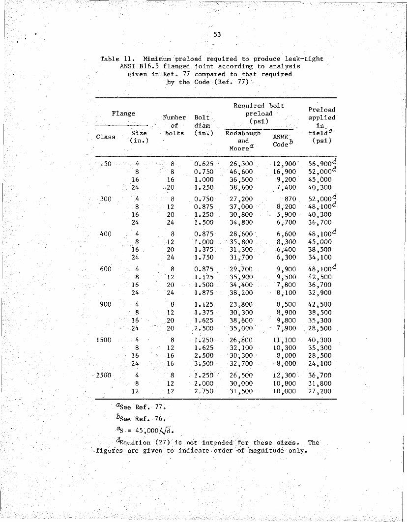
53
Table 11. Minimum preload required to produce leak-tight ANSI B16.5 flanged joint according to analysis
given in Ref. 77 compared to that required by the Code (Ref. 77)
Flange Numberof
bolts
Boltdiam(in.)
Required bolt preload (psi)
Rodabaugh ^„ a"da Coda6Moorea
Preloadapplied
infield*5(psi)Class Size
(in.)
150 4 8 0.625 26,300 12,900 56,900^8 8 0.750 46,600 16,900 52,000**
16 16 1.000 36,500 9,200 45,00024 20 1.250 38,600 7,400 40,300
300 4 8 0.750 27,200 870 52,000*J8 12 0.875 37,000 8,200 48,100*2
16 20 1.250 30,800 5,900 40,30024 24 1.500 34,800 6,700 36,700
400 4 8 0.875 28,600 6,600 48,100*28 12 1.000 35,800 8,300 45,000
16 20 1.375 31,300 6,400 38,50024 24 1.750 31,700 6,300 34,100
600 4 8 0.875 29,700 9,900 48,100*28 12 1.125 35,900 9,500 42,500
16 20 1.500 34,400 7,800 36,70024 24 1.875 38,200 8,100 32,900
900 4 8 1.125 23,800 8,500 42,5008 12 1.375 30,300 8,900 38,500
16 20 1.625 38,600 9,800 35,30024 20 2.500 35,000 7,900 28,500
1500 4 8 1.250 26,800 11,100 40,3008 12 1.625 32,100 10,300 35,30016 16 2.500 30,300 8,000 28,50024 16 3.500 32,700 8,000 24,100
2500 4 8 1.250 26,500 12,300 36,7008 12 2.000 30,000 10,800 31,800
12 12 2.750 31,500 10,000 27,200
^ee Ref. 77.^See Ref. 76. aS = 45»000A/d.“^Equation (27) is not intended for these sizes. The
figures are given to indicate order of magnitude only.

54
when the tightening operation is completed, in-service failure does not generally occur. However, if the bolts are subject to stress corrosion cracking, the high preload induced when the bolts are tightened enough to prevent the joint from leaking can cause in-service failure.
Considerable research on bolted, gasketed joints has been coordinated by the Pressure Vessel Research Committee's (PVRC) Subcommittee on Bolted Flanged Connections. A literature survey80 of gasket leakage testing sponsored by this subcommittee concluded that the m and y factors given in the Code must be reevaluated and improved to reflect the fact that they depend not only on gasket type and material, but also on gasket width, surface finish of the flanges, gasket stress, assembly stress, internal pressure, contained medium, and permissible leakage rate. As a result, the Gasket Test Program II was initiated by PVRC.
A literature survey®1 of methods of analysis of bolted-flanged connections was also published under the sponsorship of the Subcommittee on Bolted Flanged Connections. It discusses analysis of the bolting, including tightening and the bolt stresses.
An exploratory gasket test program®^ was conducted to narrow down and better define the Gasket Test Program II parameters. A computer data bank containing the exploratory test parameters and results was established . The Gasket Test Program II is well under way. A survey of flanged-joint user experience has been written by J. R. Payne and is expected to be approved for publication as a Welding Reseaveh Council Bulletin^ Another report entitled PVffl Milestone Gasket Tests — First Results by A. Bazerqui and L. Marchand8® was recently published. The Milestone Tests are part of the Gasket Test Program II. In these tests, complex load/pressure sequences were used to determine leakage performance and deformation response at room temperature of four types of gaskets:(1) a spiral-wound asbestos-filled gasket with an outer compression ring;(2) a compressed-asbestos gasket with a rubber binding; (3) a flat stainless steel, doubled-jacketed, asbestos-filled gasket; and (4) a soft-iron oval-ring joint gasket. It is anticipated that the main parameters affecting gasket performance will be identified and will serve as a basis for defining a simplified production test procedure, which should eventually result in more meaningful gasket design factors.
The joint diagram for a gasketed joint is considerably different from the joint diagram for a hard-joint. The gasket is relatively soft and usually exhibits much more nonlinear load-deformation behavior.
In any joint with multiple bolts that are tightened sequentially, the preload applied to the first bolt is changed when subsequent bolts are preloaded. This "cross-talk" is especially important in pressure- retaining joints.

55
9= PRELOAD ASSURANCE
It is important that steps be taken to assure that bolts have been preloaded properly. During a walk-down inspection of a nuclear power plant, a concrete anchor bolt was discovered that had been cut off and inserted in the hole without being attached. Placement of the reinforcing steel in the concrete was such that it was in the way of the hole for the concrete anchor bolt. Therefore, the workman just cut the bolt off and put it in place so that it looked like it had been installed properly.
In another instance, examination of pipe-support anchor plates at the Clinton reactor revealed a number of improperly installed anchor plates.8lt For example, in the case of one plate used to anchor a pipe support in the reactor core isolation cooling system, one of the four concrete expansion bolts had been welded to the plate instead of being properly attached in the floor.
Both of the cases cited above were instances of gross incompetence or dishonesty in the installation of the bolts. Steps to assure proper preload in such cases should emphasize training and communication with the workmen to make sure they know how to properly preload the bolts, to make sure they want to install the bolts properly, and to make sure that they understand the importance of correctly preloading each bolt.
Proper preload, as we have seen, is critical to the performance of bolted connections. In some instances the preload must be controlled with considerable precision. Complete assurance that a joint has been preloaded properly requires that the stretch of the bolt be measured. This requires that the bolt be measured before tightening and again when the preload is verified. As discussed in a previous section, the methods avallable for measuring bolt stretch include strain gages, ultrasonics, micrometer calipers, and datum rods and/or depth micrometers. Unfortunately, any of these methods requires that careful documentation of the original length of each individual bolt be maintained. This would be a formidable task and would require special procedures for assuring that the original length measurements themselves were accurate.
Guidance for how best to assure that bolts have been properly pre- loaded is contained in "Sect. 6. Inspection” of Ref. 1. Major points included are as follows:
1. An inspector should observe the installation of bolts to determine that the selected procedure is properly used and should determine that all bolts are tightened.
2. A procedure is given for using a torque wrench for assuring the bolts have been preloaded properly.
Their first point is endorsed. However, the use of a torque wrench for assuring that the preloading has been applied properly is of questionable value because of the inherent scatter in the preload-torque relationship.
Not only is it necessary to assure that the bolts were preloaded properly when they were installed, but consideration should also be given to checking the preload in selected critical bolts after severe upset conditions such as water-hammer or an earthquake. Such events can cause severe loss of preload.

56
10. SUMMARY
A number of bolted joints have failed in nuclear Class 1 component supports and other safety-related equipment. The most frequently cited cause of failure has been stress corrosion cracking. Whenever possible, bolting materials that are known to not be susceptible to stress corrosion cracking should be used. Because stress corrosion cracking generally requires the presence of a locally high stress, control of the maximum bolt preload can be used to avoid such failures if materials that are susceptible to stress corrosion cracking must be used. In the usual bolted joint design procedure, only the minimum preload is controlled.
Two procedures for the design of bolted joints are presented, and the importance of controlling the maximum as well as the minimum preload is stressed. The methods available for applying and measuring preload and their accuracies are presented. For many critical applications, torque control cannot yield sufficient preload accuracy; thus, more expensive methods of measuring preload must be used.
Concrete anchor bolts are frequently used to connect component supports to the building structure. Although there have been several failures observed, recent studies indicate they will function satisfactorily if they are installed according to the manufacturers' instructions. The effects of prying action must be considered and baseplates must be carefully designed to avoid too much flexibility, which can enhance prying action.
Reactor vessel internals fasteners should be designed using the same procedures discussed for component supports. However, more attention should be given to preventing preload loss and possible loose parts. Positive mechanical means of keeping the fasteners from coming loose are recommended.
Some of the principles and problems of gasketed pressure-retaining joints are mentioned. However, the design and preloading of such joints are beyond the scope of the present report. Indeed, much research is still going on in this area.
Finally, once the joint is designed and the proper preload range is determined and applied, steps must be taken to ensure that the proper preload does indeed exist in the bolts. Traditional torque measurements are inadequate for critical joints where the proper preload range is relatively narrow, that is, less than ±25%. For critical joints, some method of measuring the bolt stretch is recommended for validating that the proper preload is applied.

57
11. RECOMMENDATIONS
Whenever possible, the problem of stress corrosion cracking should be avoided by using relatively ductile bolts that are known to be insusceptible to stress corrosion cracking in the service environment. When this approach is used, reliable preload levels can be achieved using the turn-of-nut method to preload the bolts past yield. These joints should be designed so that the minimum required preload is no more than 70% of the specified minimum tensile strength. Selection of the bolts goes beyond the material specification. Bolts and nuts are complex machine elements that must be carefully manufactured based on many years of experience. Use of nonstandard fasteners and manufacturing methods must be avoided unless they are carefully qualified. For example, standard practice is to roll the threads after heat-treatment. This has been found to produce a residual compressive stress at the root of the threads, which increases the fatigue life of bolts.
Because of the complicated stress distribution in bolts, it is important that stress-corrosion testing be conducted on prototypic bolts. Stress corrosion cracking is a localized phenomena that makes local stress conditions of overriding importance.
When designing a bolted joint, it is generally advantageous to make sure the bolt is more flexible than the clamped parts in order to minimize the load variations that the bolt will encounter during service. In addition it minimizes the preload loss that will result from embedment or relaxation.
Once a trial bolt size is selected, the acceptable preload range must be determined by detailed analysis of the joint. The minimum preload should be selected on the basis of the following factors:
1. Avoid lift-off, including careful consideration of possible prying action.
2. Minimize load variations the bolt will see to prevent fatigue.3. Avoid loosening during service by using high preload.4. Allow for the effects of embedment and relaxation, which decrease the
preload.
The maximum preload should be selected on the basis of the following factors:
1. It should not, of course, cause immediate fracture.2. It should not be so high that it leads to fatigue failure because of
the effect of high mean stress on fatigue life.3. It should not be high enough to cause stress corrosion cracking.4. It should not be high enough to damage the clamped parts.
The acceptable preload range determines how accurately the preload must be applied. Whenever the maximum acceptable preload is at least 60% more than the minimum required preload, torque control can be used to measure the preload. For smaller acceptable preload ranges, it is recommended that the preload be determined by measuring the stretch of the bolt.Direct length measurement using either micrometer calipers or a datum rod

58
and appropriate gage may be used if analysis shows them to be sufficiently accurate for the particular case at hand.
In some extreme cases strain-gaged bolts may be required to obtain sufficient accuracy. Ultrasonic methods show considerable promise.Further exploration of the costs and service applications of ultrasonic methods is strongly recommended. Any of the methods involving stretch measurement are costly and should be avoided whenever possible by designing the bolted joints so that the maximum acceptable preload exceeds the minimum by 60% or more.

59
12. ACKNOWLEDGMENTS
This work was performed under the U.S. Nuclear Regulatory Commission's ASME Code, Section III — Technical Support Program. The original manager for NRC, E. T. Baker, was succeeded by D. J. Guzy. The project was suggested by S. N. Hou of the NRC. Their support and guidance are gratefully acknowledged.
The assistance of several of my coworkers, including R. C. Hudson,R. D. Cheverton, and S. E. Moore, is also gratefully acknowledged. It was only through the assistance of W. L. Cooper that I was able to obtain Ref. 17 and, subsequently, have it translated. This translation provides some very important material that was not previously available to the U.S. technical community.
Finally, I wish to thank R. C. Gwaltney, C. B. Gland, D. J. Guzy, and A. C. Hood for careful and helpful reviews of the complete manuscript. I also thank J. H. Bickford for reviewing the first half of this report.
REFERENCES
Research Council on Structural Connections of the Engineering Foundation, Specification for Structural Joints Using ASTM AS25 or A490 Bolts, American Institute of Steel Construction, Chicago, August 14, 1980.
ASMS Boiler and Pressure Vessel Code, Section III, Nuclear Power Plant Component, Division 1, Subsection NF — Component Supports, American Society of Mechanical Engineers, New York, July 1, 1983.
Manual of Steel Construction, 8th Edition, American Institute of Steel Construction, Inc., Chicago, 1980.
J. W. Fisher and J. H. A. Struik, Guide to Design Criteria for Bolted and Riveted Joints, John Wiley and Sons, New York, 1974.
Specification for the Design, Fabrication, and Erection of Steel Safety-Related Structures for Nuclear Facilities, N-690, American Institute of Steel Construction, Chicago (to be published).
K. H. Koo, Threaded-Fastener Experience in Nuclear Power Plants, NUREG-0943, U.S. Nuclear Regulatory Commission, January 1983.
Northern States Power Company, Prairie Island 1 and 2, Docket 50- 282, LER No. 80-025R, December 3, 1980.
V. J. Colangelo and F. A. Reiser, Analysis of Metallurgical Failures, John Wiley and Sons, New York, 1974, p. 195.
S. T. Rolfe and J. M. Barsom, Fracture and Fatigue Control in Structures, Applications of Fracture Mechanics, Prentice-Hall, Inc. Englewood Cliffs, N.J., 1977, pp. 292—315.
E. J. Imhof and J. M. Barsom, "Fatigue and Corrosion-Fatigue Crack Growth of 4340 Steel at Various Yield Strengths," ASTM STP 536, American Society for Testing and Materials, Philadelphia, 1973.
D. G. Eisenhut letter to all power reactor licensees, May 19, 1980; published as Appendix D to NUREG-0577, Potential for Low Fracture Toughness and Lamellar Tearing on Component Supports.
D. G. Eisenhut, letter to all pending operating licensees and construction permit applicants, all licensees of plants under construction, May 20, 1980, Subject: Additional Guidance on"Potential for Low Fracture Toughness and Lamellar Tearing on PWR Steam Generator and Reactor Coolant Pump Supports," NUREG-0577.
H. 0. Fuchs and R. I. Stephens, Metal Fatigue in Engineering, John Wiley and sons, New York, 1980, pp. 274—75.

61
14. T. J. Dolan, "Load Relations in Bolted Joints,” Mech. Eng. 64(8), 607-11 (August 1942).
15. J. Goodman, Mechanics Applied to Engineering, vol. 1, 9th ed., Longmans, Green, and Co., London, 1930, p. 634.
16. M. F. Spotts, Design of Machine Elements, 2nd ed., Prentice-Hall, Englewood Cliffs, N.J., 1953, pp. 78—79.
17. VDI 2230: Systematic Calculation of High Duty Bolted Joints, ORNL-tr-5055, Oak Ridge National Laboratory, 1983.
18. G. A. Fazekas, "Eccentric Limit Load on Fasteners," J. Eng . Ind Trans. ASME, Ser. B, 98(3), 773—75 (August 1976).
19. G. A. Fazekas, "On Eccentrically Loaded Fasteners,” J. Eng. Ind., Trans. ASME, Ser. B, 98(3), 776—78 (August 1976).
20. E. Chesson, Jr., N. L. Faustino, and W. H. Munse, "High-Strength Bolts Subjected to Tension and Shear,” J. Struct. Div., ASCE, 91, ST5 (October 1965).
21. A. Erker, "Design of Screw Fastenings Subject to Repeated Stresses," pp. 290—300 in Proc. Int. Conf. Fatigue of Metals, September 10—14, 1956, in London; November 28—30, 1958 in New York, Institution of Mechanical Engineers, London (1956).
22. J. H. Bickford, An Introduction to the Design .and Behavior of Bolted Joints, Marcel Dekker, Inc., New York, 1981.
23. Screw-Thread Standards for Federal Services, FED-STD-H28, U.S. Government Printing Office, March 31, 1978.
24. G. H. Junker, Principle of the Calculation of High-Duty Bolted Joints, Interpretation of Directive VDI-2230, SPS, Jenkintown, Pa.
25. J. H. Bickford, Handout at Bolted Joint Seminar, September 14—15, 1982, Middletown, Conn.
26. -Ing. Nabil Motosh, "Determination of Joint Stiffness in Bolted Connections," J. Eng. Ind., Trans. ASME, Ser. B, 98(3), 858—61 (August 1976).
27. A. K. Abd El-Latif and H. H. Ziada, "Determining the Normal Stiffness of Joint Faces," J. Eng, Appl. Sci., Ser. B, 90(1), 97—106 (February 1968).
28. H. H. Ziada and A. K. Abd El-Latif, "Determination of Bolted Joint Stiffness from Load Deformation Analysis," ASME Paper 82-DE-W-3 (1983).
62
29. R. Connolly and R. H. Thornley, "Determining the Normal Stiffness of Joint Faces,” J. Eng. Ind., Trane. ASME, Ser. B, 90(1), 97—106 (February 1968).
30. J. T. Pindera and Y. Sze, "Influence of the Bolt System on the Response of the Face-to-Face Flanged Connections," Paper G2/6 in 2d Int. Conf. Stvuotwral Meehanies in Reactor Technology, Berlin, Germany, September 10—14, 1973, Vol. 3, Reactor Vessels (1973).
31. E. Chesson, Jr., and W. H. Munse, Studies of the Behavior of High- Strength Bolts and Bolted Joints, Engineering Experiment Bulletin 469, University of Illinois, Urbana (1965).
32. J. Tajima, Effect of Relaxation and Creep on the Slip Load of High Strength Bolted Joints, Structural Design Office, Japanese National Railways, Tokyo (June 1964).
33. R. B. Heywood, Designing Against Fatigue, Chapman and Hill, London, 1962.
34. L. Martinaglia, "Bolted Connections: The State of the Art,"Sahweiter Bauzeitung 119 (March 1942); Pametrada Trans. No. 1 (July 1948).
35. D. McCormick, "A Guide to Fastening and Joining," Des . Eng . 53(6) , F5-F27 (June 1982).
36. R. C. Cipolla, "Fracture Mechanics Based Methodology for Assessing the Integrity of High Strength Bolting Materials," presented at Bolting Degradation or Failure in Nuclear Plants Seminar, November 3, 1983, Knoxville, Tenn.
37. Torquing of Huts in Aircraft Engines, Progress Report No. 1, Society of Automotive Engineers, December 1943.
38. C. C. Osgood, Fatigue Design, 2d ed., Pergamon Press, 1982, p. 281.
39. N. Motosh, "Development of Design Charts for Bolts Preloaded up to the Plastic Range," J. Eng. Ind., 849-51, August 1976.
40. D. D. Fuller, "Friction," pp. 3—35 in Standard Handbook for Mechanical Engineers, 7th ed., T. Baumeister and L. S. Marks, McGraw-Hill, New York, 1967.
41. R. 0. Parmley, ed., Standard Handbook of Fastening and Joining, McGraw-Hill, New York, 1977, pp. 1-25.
42. C. P. Coughlen, Nut and Bolt Loading Curves, ORNL-578, February 15, 1950.
43. "Fastener Preload," Machine Design 1982 Fastening and Joining Reference Issue 54(26), 49—50 (November 18, 1982).
63
44. A. S. Cornford, "Bolt Preload —How Can You Be Sure It's Right!" Mach. Des., 78-82 (March 6, 1975).
45. W. C. Stewart, "Bolted Joints," p. 175 in ASME Handbooks Metals Engineering Design, ed. 0. J. Horger, McGraw-Hill, New York, 1953.
46. J. C. Blake and H. J. Kurtz, "The Uncertainties of Measuring Fastener Preload," Mach. Des., 128—31 (September 30, 1965).
47. E. C. Petrie, "Flanged Piping Joints, Methods for Applying and Determining Bolt Stresses," Heat./Piping/Air Cond. 8(6), 303—9 (June 1936).
48. J. T. Boys and P. W. Wallace, "Controlled Forces in Bolted Joints," Chart. Mech. Eng. 23(10), 53—56 (November 1976).
49. J. T. Boys and P. W. Wallace, "Controlled Forces in Bolted Joints — Developing a Controller," Chart. Mech. Eng. 24(2), 55—58 (February 1977).
50. "Thread Forms and Torque Systems Boost Reliability of Bolted Joints," Prod, Eng. 48(12), 37—41 (December 1977).
51. J. N. Robinson, M. I. Lundin, and 1. Spiewak, Development of Ring- Joint Flanges for Use in the HRE-2, ORNL-3165, December 6, 1961.
52. H. J. McFaul, "An Ultrasonic Device to Measure High-Strength Bolt Preloading," Mater. Eval. 32(11), 244—48 (November 1974).
53. J. S. Heyman, "A CW Ultrasonic Bolt-Strain Monitor," Exp. Mech., 183-87 (May 1977).
54. J. H. Bickford, "Ultrasonic Control of Bolt Preload," Piping Codes and Tests, personal communication, September 14, 1982.
55. T. Sakai, T. Makino, and H. Toriyama, "Bolt Clamping Force Measurement with Ultrasonic Waves," Trans. JSME 43(366), 723—29(February 1977).
56. V. M. Bobrenko et al., "Ultrasonic Method of Measuring Stresses in Parts of Threaded Joints," Sov. J. Nondestru. Test. 10(1)(January-February 1974 and November 1974).
57. J. H. Bickford, "Ultrasonic Measurement of Bolt Stretch," pp. 157—81 in An Introduction to the Design and Behavior of Bolted Joints,Marcel Dekker, Inc., New York, 1981.
58. J. H. A, Struik, A. 0. Oyeledun, and J. W. Fisher, "Bolt Tension Control with a Direct Tension Indication," Eng. J., AISC 10(1), 1—5 (1973).

64
"Bolt Tightness Indicated by Wavy Flange," Mouth. Des. 55(26), 2 (November 17, 1983).
C. C. Osgood, "How Elasticity Influences Bolted-Joint Design,Preload and Fatigue Concepts," Mach. Des. 44(6), 104 (1972).
"Appendix XII, Design Considerations for Bolted Flange Connections," ASME Boiler and Pressure Vessel Codet Section III3 Rules for Construction of Nuclear Power Plant Components Division 1 — Appendices, American Society of Mechanical Engineers, New York, 1983.
M. E. Looram, J. H. Bickford, J. L. Seminara, and J. R. Leth, A Study of Bolting Problems, Tools, and Practices in the Nuclear Industry, EPRI NP-2174, Electric Power Research Institute, December 1981.
USNRC, IE Bulletin 79-02, "Pipe Support Base Plate Designs Using Concrete Expansion Anchor Bolts,” March 1979. Available for inspection and copying for a fee in the NRC Public Document Room, 1717 H St., NW, Washington, DC 20555.
USNRC, IE Bulletin No. 79-02 (Revision No. 1), "Pipe Support Base Plate Designs Using Concrete Expansion Anchor Bolts," June 21,1979. Avallable for inspection and copying for a fee in the NRC Public Document Room, 1717 H St., NW, Washington, DC 20555.
USNRC, IE Bulletin No. 79-02 (Revision No. 1, Supplement No. 1), "Pipe Support Base Plate Designs Using Concrete Expansion Anchor Bolts," August 20, 1979. Available for inspection and copying for a fee in the NRC Public Document Room, 1717 H St., NW, Washington,DC 20555.
Teledyne Engineering Service, Summary Report on "Generic Response to USNRC IE Bulletin Number 79-02, Base Plate/Concrete Expansion Anchor Bolts," August 30, 1979, 303 Bear Hill Road, Waltham, MA 02154.
R. D. Ciatto and R. R. Boentgen, "Strength of Concrete Expansion Anchors for Pipe Supports," pp. 247—62 in Effects of Piping Restraints on Piping Integrity, PVP-40 (1980). Published by ASME, 345 E. 47th St., New York, NY 10017.
G. L. Clark, "Installation of Concrete Expansion Anchors at the Fast Flux Test Facility," pp. 263—72 in Effects of Piping Restraints on Piping Integrity, PVP-40 (1980). Published by ASME, 345 E. 47th St., New York, NY 10017.
M. R. Lindquist, Final Report USNRC Anchor Bolt Study, Data Survey and Dynamic Testing, NUREG/CR-2999, U.S. Nuclear Regulatory Commission (HEDL-MISC-7246), December 1982.
65
70. American Concrete Institute, "Code Requirements for Nuclear Safety Related Concrete Structures (ACI 349-76)Appendix B, 1979 Supplement .
71. L. J. DiLuna and J. A. Flaherty, An Assessment of the Effect of Plate Flexibility on the Design of Moment-Resistant Baseplates, ASME paper 79-PVP-50.
72. C. P. Hou, "Design Procedures for a Moment Resistant Base Plate with the Consideration of Plate Flexibility," pp. 273—64 in Effects of Piping Restraints on Piping Integrity, PVP-40 (1980). Published by ASME, 345 E. 47th St., New York, NY 10017.
73. G. S. Haviland, "Designing with Threaded Fasteners," Mech. Eng. 105(10), 16-31 (October 1983).
74. "Mechanical Locking Devices," RDT Standard M 6-2T, Division of Reactor Development and Technology, United States Atomic Energy Commission, March 1969.
75. ASME Boiler and Pressure Vessel Code, Section IIIt Rules for Construction of Nuclear Power Plant Components 3 Division 1 — Subsection NGS Core Support Structures, American Society of Mechanical Engineers, July 1, 1983.
76. "Appendix XI, Rules for Bolted Flange Connections for Class 2 and 3 Components and Class MC Vessels,” ASME Boiler and Pressure Vessel Code, Section III, Rules for Construction of Nuclear Power Plant Components, Division 1 — Appendices, American Society of Mechanical Engineers, New York, 1983, pp. 323—43.
77. E. C. Rodabaugh and S. E. Moore, Evaluation of Bolting and Flangesof ANSI B16.S Flanged Joints: ASME Part A Design Rules, ORNL/Sub-2913-3, August 1976.
78. D. B. Wesstrom and S. E. Bergh, "Effects of Internal Pressure on Stresses and Strains in Bolted-Flanged Connections," Trans. ASME 73(5), 553-68 (July 1951).
79. E. C. Petrie, "The Ring Joint, Its Relative Merit and Application,” Heat./Piping/Air Cond. 9(4), 213-20 (April 1937).
80. H. Kraus, "Interpretive Report on Gasket Leakage Testing,” NRC Bull. 262, October 1980.
81. A. E. Blach and A. Bazergui, "Methods of Analysis of Bolted Flanged Connections — A Review," WRC Bull. 271, October 1981•
H. D. Raut, A. Bazergui, and L. Marchand, "Gasket Leakage Behavior Trends," WRC Bull. 271, October 1981.
82.

66
83. A. Bazergui and L. Marchand, "PVRC Milestone Gasket Tests — First Results," WRC Bull. 292, February 1984.
84. "INFO QA Inspection Prompts Study — and Stop — of Pipe Work at Clinton,” Nucleonics Week 25(2), 1 (January 12, 1984).

67
Internal
NUREG/CR-3853 ORNL-6093Dist. Category RM
Distribution
1. C. R. Brinkman 17. J. G. Merkle2. R. D. Cheverton 18. S. E. Moore3. J. A. Clinard 19. D. G. 0'Conner4. C. W. Collins 20. C. B. Oland5. W. L. Cooper 21. C. E. Pugh6. J. M. Corum 22. H. E. Trammell7. D. M. Eissenberg 23. G. D. Whitman8. D. S. Griffith 24. L. V. Wilson9. R. C. Gwaltney 25-29. G. T. Yahr
10. W. R. Hendrich 30. F. C. Zapp11. R. L. Huddleston 31-34. Structural Design Criteria,12. R. C. Hudson Bldg. 9204-1, MS 1113. Y. L. Lin 35. ORNL Patent Office14. W. L. Greenstreet 36. Central Research Library15. A. P. Malinauskas 37. Document Reference Section16. S. S. Manson 38-39. Laboratory Records Department
(Consultant) 40. Laboratory Records (RC)
External Distribution
41. J. H. Bickford, 217 Smith St., Middletown, CT 06457-999042. W. R. Gall, P.0. Box 334, Oak Ridge, TN 3783043. Office of Assistant Manager for Energy Research and Development,
Department of Energy, 0R0, Oak Ridge, TN 3783144-45. Technical Information Center, DOE, Oak Ridge, TN 37831
46-345. Given distribution as shown under category RM (NTIS-10)346-410. Special ASME Code Distribution (by NRC)