Embed Size (px)
Citation preview
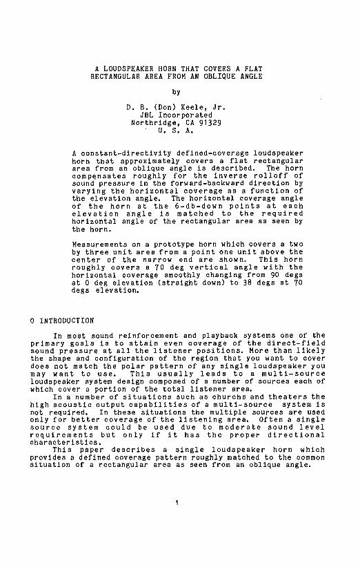
A LOUDSPEAKER HORN THAT COVERS A FLAT 2052 (D-7)
RECTANGULAR AREA FROM AN OBLIQUE ANGLE
D. B. (Don) Keele, Jr.
JBL Incorporated
Northridge, California
Presentedat ^_o, othe 74thConvention1983October 8-12New York ®
Thispreprint has been reproducedfrom the author's advancemanuscript, withoutediting, correctionsor considerationbythe ReviewBoard. TheAES takes no responsibilityfor thecontents.
Additionalpreprintsmay be obtainedby sendingrequestand remittance to the Audio Engineering Society, 60 East42nd Street, New York,New York10165USA.
All rights reserved.Reproductionof this preprint, oranyportion thereof, is not permitted without direct permissionfrom the Journalof the Audio EngineeringSociety.
AN AUDIO ENGINEERINGSOCIETYPREPRINT
A LOUDSPEAKER HORN THAT COVERS A FLATRECTANGULAR AREA FROM AN OBLIQUE ANGLE
by
D. B. (Don) Keele, Jr.JBL Incorporated
Northrldge, CA 91329U. S. A.
A constant-directivity defined-coverage loudspeakerhorn that approximately covers a flat rectangulararea from an oblique angle is described. The horncompensates roughly for the inverse rolloff ofsound pressure in the forward-backward direction byvarying the horizontal coverage as a function ofthe elevation angle. The horizontal coverage angleof the horn at the 6-db-down points at eachelevation angle is matched to the requiredhorizontal angle of the rectangular area as seen bythe horn.
Measurements on a prototype horn which covers a twoby three unit area from a point one unit above thecenter of the narrow end are shown. This hornroughly covers a 70 deg vertical angle with thehorizontal coverage smoothly changing from 90 degsat 0 deg elevation (straight down) to 38 degs at 70degs elevation.
0 INTRODUCTION
In most sound reinforcement and playback systems one of theprimary goals is to attain even coverage of the direct-fieldsound pressure at all the listener positions. More than likelythe shape and configuration of the region that you want to coverdoes not match the polar pattern of any single loudspeaker youmay want to use. This usually leads to a multi-sourceloudspeaker system design composed of a number of sources each ofwhich cover a portion of the total listener area.
In a number of situations such as churchs and theaters thehigh acoustic output capabilities of a multi-source system isnot required. In these situations the multiple sources are usedonly for better coverage of the listening area. Often a singlesource system could be used due to moderate sound levelrequirements but only if it has the proper directionalcharacteristics.
This paper describes a single loudspeaker horn whichprovides a defined coverage pattern roughly matched to the commonsituation of a rectangular area as seen from an oblique angle.

1 HISTORY
In the past, solutions to typical coverage situationsincluded: 1. Arrays of loudspeakers (Klepper [1], Schneider [2],Jones [3]), 2. Gradient sources (Hilliard [4], Olson [5]), 3.Horns (Wente [6], Klipsch [7], Keele [8], Henrikson [9]), and 4.Central clusters (Malmlund [10], Patronis [11], Rosner [12],Figwar [13]).
2 THEORY
2.1 Required Angular Coverage
Fig. 1 shows the general situation of an acoustic sourceabove and on the center line of a rectangular region. The taskis to derive the functional relationship between the requiredhorizontal coverage angle (as seen by the source) and theelevation angle.
In Fig. 1 the source is H units above the plane of therectangle and L1 units behind and on the center line of therectangle. The rectangle is W units wide and L units long. Theelevation angle is alpha (defined with 0 degs straight down) andthe total included horizontal coverage angle is beta.
Assuming a rectangular coordinate system centered directlybelow the source on the plane of the rectangle with the positivex axis bisecting the rectangle, analysis of Fig. 1 yields thefollowing relationships:
for the elevation angle
alpha = arctan (x/H) (I)
where
x is the distance from the origin to an arbitrarypointon the center line of the rectangle (thex axis),
H is the height of the source over the plane ofthe rectangle; and
for the horizontal coverage angle (as seen by the source)
beta = 2 * arctan (W / (2 * sqrt(x^2 + H^2)) (2)
where
W is the width of the rectangle.
Note: all equations in this paper are shown using standardcomputer language notation (BASIC) where * = multiply, / =divide, ^ = exponenttation, sqrt = squareroot function, arctan =inverse tangent function, etc.
Two sets of reference elevation and horizontal coverage anglescan be defined at the front and rear of the rectangle:
at the front (x = 41)
alpha1 =arctan (L1/H), (3)
beta1 = 2 *arctan (W / (2 * sqrt(Ll^2 + H^2)); (4)
at the rear (x = L1 + L)
alpha2 = arctan ((L1 + L) / H), and (5)
beta2 =
2 * arctan (W / (2 * sqrt((L1 + L)^2 + H^2)). (6)
A more general analysis of a source over a plane may be found inCable [14].
2.2 Horn Design
Once the horns horizontal coverage angle is known as afunction of the elevation angle (eqs. 1, 2) it is straightforward to compute the contours of the horn sidewalls at eachelevation angle. Well known sidewall contours as shown in[7J, [8], [9], and Smith [15] can be used. The generated hornbell section can then be Joined to a driver coupler with a throatsection of exponential or other area increase function [7], [8],[9], and [15].
3 EXPERIMENT
3.1 System Parameters
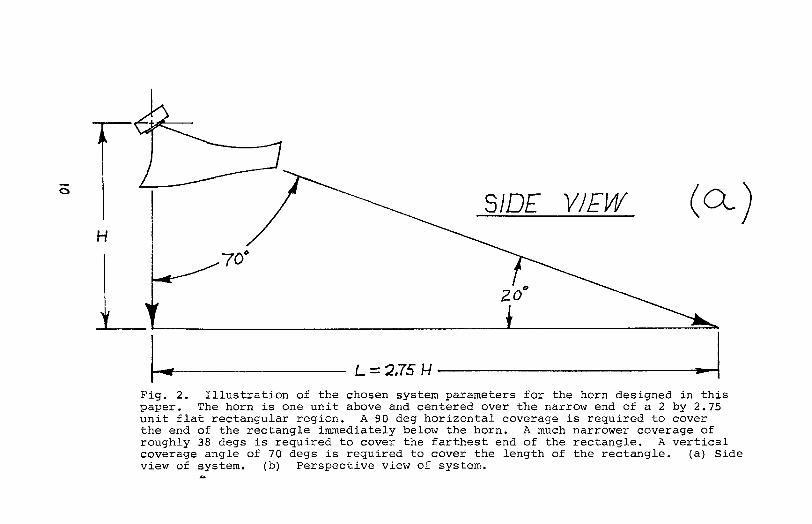
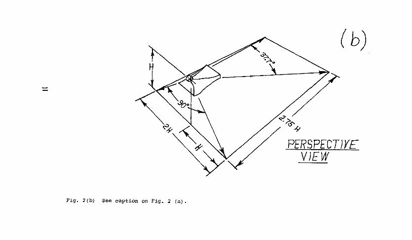
A defined coverage horn was designed to cover a 2 by 2.75(roughly 2 by 3) unit rectangle from a point one unit above thecenter of the narrow end. These requirements result in thefollowing system parameters:
rectangle length = L = 2.75,
rectangle width = W = 2.0,
source height = H = 1.0, and
source offset = L1 = 0.0.
The horn was to be used with a one inch diameter throatcompression driver and have an operating range of roughly 500 Hzto 12.5 kHz.
3.1 Elevation and Coverage Angles
Using eqs. I (3 - 6), these system parameters result in thefollowing elevation and horizontal coverage angles:
at the front of the rectangle (x = 0, source end)
elevatlonangle= alpha1 = 0.0 degs (straightdown),
coverage angle = beta1 = 90.0 degs;
at the rear of the rectangle (x = 2.75)
elevation angle = alpha2 = 70.0 degs,
coverage angle = beta2 = 37.7 degs.
Fig. 2 shows side and perspective views of the selected systemparameters.
3.3 Horn Design
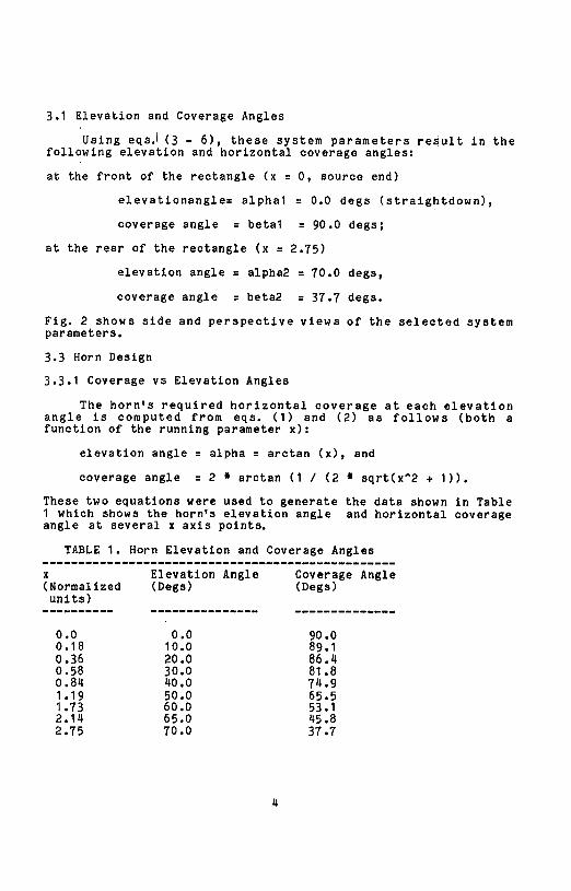
3.3.1 Coverage vs Elevation Angles
The horn's required horizontal coverage at each elevationangle is computed from eqs. (1) and (2) as follows (both afunction of the running parameter x):
elevation angle = alpha = aretan (x), and
coverage angle = 2 * arctan (1 / (2 a sqrt(x^2 + 1)).
These two equations were used to generate the data shown in Table1 which shows the horn's elevation angle and horizontal coverageangle at several x axis points.
TABLE 1. Horn Elevation and Coverage Angles........... .--.----.----.--.........--........--....__.__
x Elevation Angle Coverage Angle(Normalized (Degs) (Degs)units)
--....--.... .--.--. .... .I.... --.------.--.--.....
0.0 0.0 90.00.18 10.0 89.10.36 20.0 86.40.58 30.0 81.80.84 40.0 74.91.19 50.0 65.51.73 60.0 53.12.14 65.0 45.82.75 70.0 37.7
3.3.2 Sidewall Contours
The sidewall contour generating equation shown in [eq.p.409, 15], and Keele patent [16] was used to define the sidewallcontour shapes in both planes to yield the smoothest off-axisfrequency response:
y = a + b # x + c # x_n (7)
wherex = distance from throat of horn or source aperture
gap,y = horn contour dimension at point x,a = constant which defines half width (or half height)
of start of horn (either the throat radius orone-half the aperture gap width, this dimensionsets the highest operating frequency of the horn upto which full rated beamwidth is maintained),
b= constant which defines the slope of the sidewallnear the throat or aperture gap of the horn(b = tan (desired-coverage-angle/2)),
c = constant which sets the amount of end flaring of thesidewall (flaring of the sidewall near the mouthof the horn mlnimises mid-range narrowing [8], and
n: power constantwhich deflnestherapidityof side-wall flare (= 7 for this design).
Eq. 7 was used to define the horizontal sidewall shape of thehorn at each elevation angle in a smooth progression. Thehorizontal mouth width of the horn was constant for all verticalelevation angles. The vertical sidewalls (0 deg and 70 degcontours) were also designed using eq. 7. The general teachingsof patent [16] were used to design the rest of the horn(exponential throat section etc.).
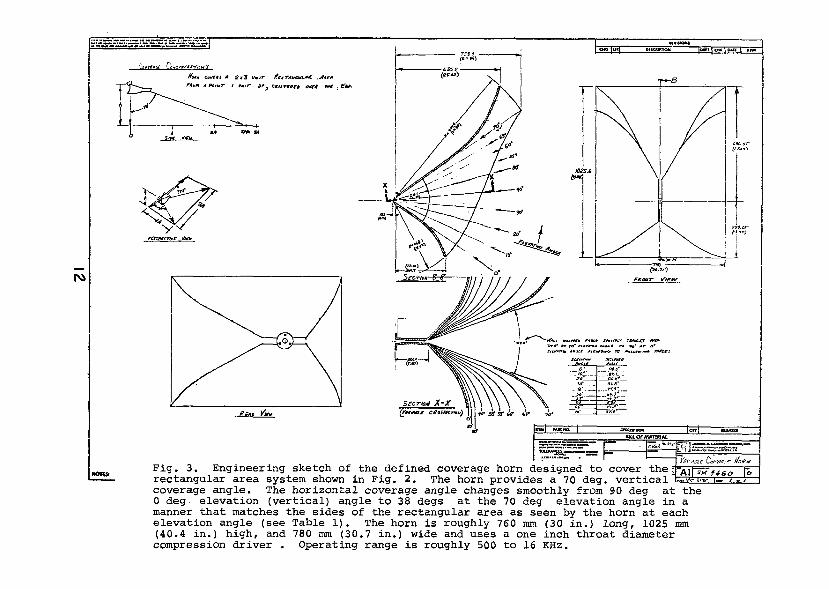
3.3.3 Horn Drawing
The complete horn design is shown in Fig. 3 and in isometricsketch form in Fig. 4. The horn is roughly 760 mm (30 in) long,1025 mm (40.4 in) high, and 780 mm (30.7 in) wide.
The selected mouth dimensions maintain horizontal beamwidthcontrol down to roughly 850 Hz for the narrow-angle (38 deg)coverage long-throw part of the horn and down to 360 Hz for thewide-angle (90 deg) coverage short-throw portion of the horn.
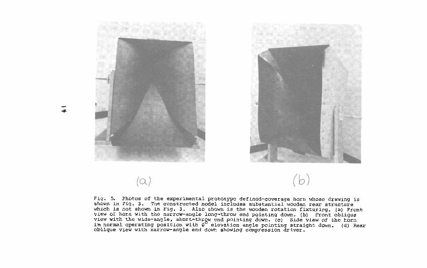
3.4 Model Construction
The model was constructed from wood and modeling compound.The complex compound curve shapes of the horizontal walls werebuilt up from each individual horizontal contour at eachelevation angle (at roughly 10 deg angle increments) much thesame way the contour of an airplane wlng is built up.
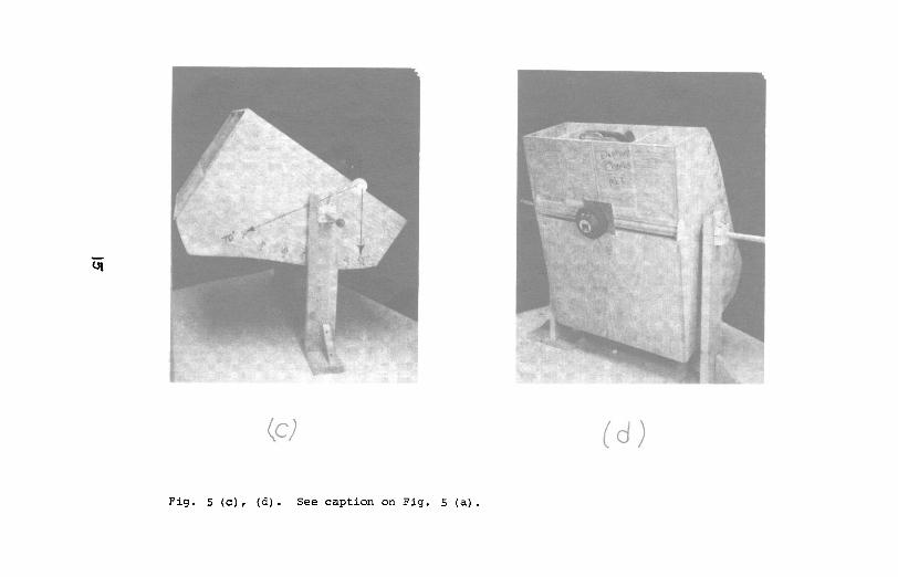
Photos of the completed experimental prototype hornare shown in Fig. 5.
3.5 Model Measurements
The model was tested using a JBL model 2425 compressiondriver. All measurements were done over a large ground plane(flat eonerete surface) at a distance of 2 meters from the mouthof the horn using the technique of Gander [17]. A fixture wasconstructed so that the horn could be rotated easily in theelavation plane (Fig. 5).
3.5.1 Zero Degree Elevation Frequency Response and Impedance
Fig. 6 shows the measured 0 deg elevation (90 deg horizontalcoverage at this elevation angle) frequency response andimpedance of the horn. This curve was run at 2 meters from themouth with an input voltage of 2.83 vrms (equivalent to 1 watt 1meter in free space). Due to the constant direetivitycharacteristics of the horn the frequency response clearly showsthe power response of the compression driver. The drivers powerresponse is roughly flat from 500 Hz to 3 kHz with a 6 dB peroctave rolloff beyond.
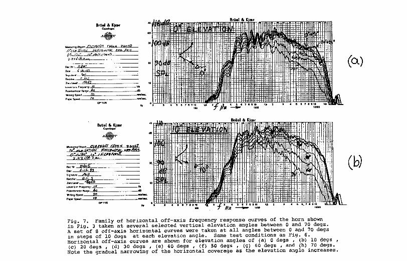
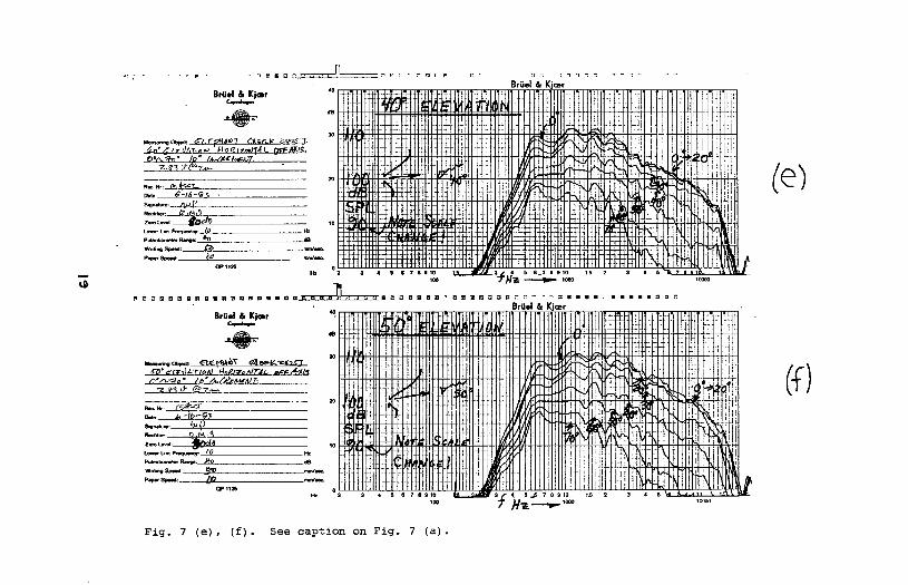
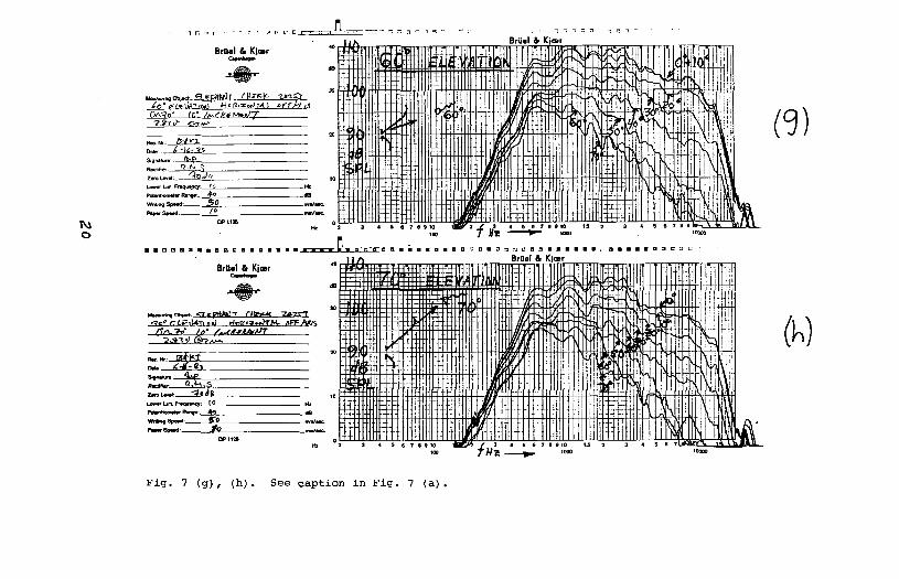
3.5.2 Horizontal Off-Axis Response Curves
Fig. 7 shows a family of horizontal off-axis frequencyresponse curves at several selected vertical elevation angles.At each elevation angle, 8 response curves were taken at all off-axis horizontal angles between 0 to 70 degs in steps of 10 degs.Eight complete sets of horizontal off-axis curves were gatheredat all elevation angles between 0 and 70 degs in steps of 10degs. Levels have been preserved from one set to another withthe SPL indicated on the graphs.
These horizontal response curves show a well behaved off-axis behavior that progressively gets narrower and narrower asthe elevation angle increases. Again the constant directivitynature of the horn shows up very clearly in the uniformlyparallel off-axis curves.
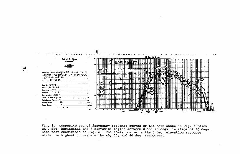
3.5.3 Vertical Off-Axis Response Curves
Fig. 8 shows a composite set of off-axis frequency responsecurves taken at all elevation angles between 0 and 70 degs insteps of 10 degs (all at 0 deg horizontal angle). The 40 and 50deg curves appear to exhibit the highest sensitivity.
The desired highest sensitivity at the 70 deg elevationangle is not evident. Thus this horn will only partiallycompensate for the inverse rolloff of sound pressure in theforward-backward direction.
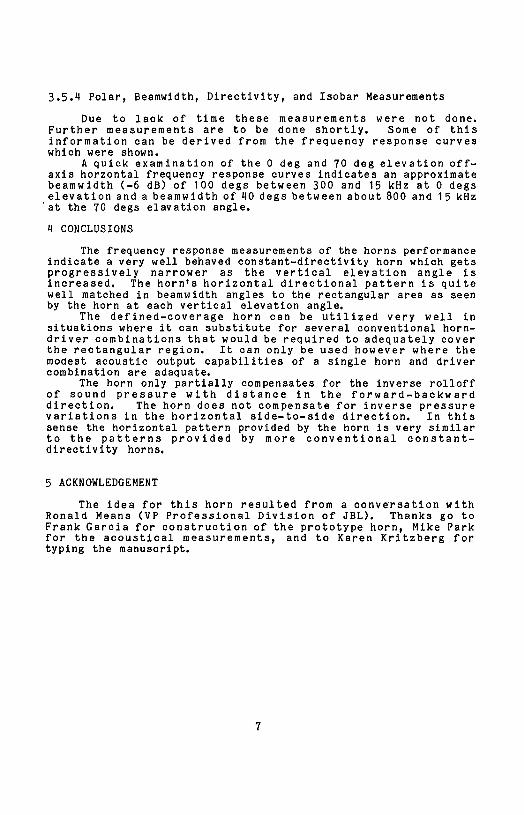
3.5.4 Polar, Beamwidth, Directivity, and Isobar Measurements
Due to lack of time these measurements were not done.Further measurements are to be done shortly. Some of thisinformation can be derived from the frequency response curveswhich were shown.
A quick examination of the 0 deg and 70 deg elevation off-axis horzontal frequency response curves indicates an approximatebeamwidth (-6 dB) of 100 degs between 300 and 15 kHz at 0 degselevation and a beamwidth of 40 degs between about 800 and 15 kHz_at the 70 degs elavation angle.
4 CONCLUSIONS
The frequency response measurements of the horns performanceindicate a very well behaved constant-directivtty horn which getsprogressively narrower as the vertical elevation angle isincreased. The horn's horizontal directional pattern is quitewell matched in beamwidth angles to the rectangular area as seenby the horn at each vertical elevation angle.
The defined-coverage horn can be utilized very well insituations where it can substitute for several conventional horn-
driver combinations that would be required to adequately coverthe rectangular region. It can only be used however where themoaest acoustic output capabilities of a single horn and drivercombination are adaquate.
The horn only partially compensates for the inverse rolloffof sound pressure with distance in the forward-backwarddirection. The horn does not compensate for inverse pressurevariations in the horizontal side-to-side direction. In thissense the horizontal pattern provided by the horn is very similarto the patterns provided by more conventional constant-directivity horns.
5 ACKNOWLEDGEMENT
The idea for this horn resulted from a conversation with
Ronald Means (VP Professional Division of JBL). Thanks go toFrank Gareia for construction of the prototype horn, Mike Parkfor the acoustical measurements, and to Karen Kritzberg fortyping the manuscript.
6 REFERENCES
[1] D. L. Klepper, D. W. Steele, "Constant DirectionalCharacteristics from a Line Source Array," J. Audio Eng. Soc.,(July 1963).
[2] A. W. Schneider, "Sound Systems at the Two New YorkWorld's Fairs," J. Audio Eng. Soc., (April 1968).
[3] E. S. Jones, "Providing Foldback with Out-of-PhaseLoudspeakers," J. Audio Eng. Soc., (April 1971).
[4] J. K. Hilliard, "Unbaffled Loudspeaker Column Arrays,,,J. Audio Eng. Soc., (Dec. 1970).
[5] H. F. Olson, "Gradient Loudspeakers," J. Audio Eng.Soc., (March 1973).
[6J E. C. Wente and A. L. Thuras, "Auditory Perspective --Loud Speakers and Microphones," Symposium on Auditory PerspectiveBell Tel. Labs., Inc., (Jan. 1934).
[7] P. W. Klipsch, "A High Quality Loudspeaker of SmallDimensions," J. Acoust. Soc. of America, vol. 17, no. 3, PP. 254-258 (Jan. 1946).
[8] D. B. Keele, Jr., "What's So Sacred About ExponentialHorns?," presented at the 51st Convention of the AudioEngineering Society, J. Audio Eng. Soc. (Abstracts), vol. 23, p.492 (1975 July/Aug), preprint 1038.
[9] C. A. Henrikson and M. S. Ureda, "The Manta-Ray Horns,"J. Audio Eng. Soc. , vol. 26, pp 629-634 (Sept. 1978).
[10] W. A. Malmlund and E. A. Wetherill, "An Optical Aid forDesigning Loudspeaker Clusters," J. Audio Eng. Soc., (Jan.1965).
[11] E. T. Patronis, "The Georgia Institute of TechnologyStadium Sound System," J. Audio Eng. Soc., (Oct. 1975).
[12] A. Rosner and L. S. King, "New Mobile SoundReinforcement System for the Metropolitan Opera/New YorkPhilharmonic Orchestra Park Concerts," J. Audio Eng. Soc., (Sept.1977 ).
[13] J. J. Figwar, "The Singapore National Stadium SoundSystem," J. Audio Eng. Soc., (Dec. 1977).
[14] C. R. Cable, "The Qualification of LoudspeakerDlrectivity Factor in Sound Reinforcement System Design,"J. Audio Eng. Soc., (July/Aug. 1975).
[15] D. Smith, D. B. Keele, Jr., and J. Eargle,"Improvements in Monitor Loudspeaker Systems," vol. 31, pp 422(June 1983).
[16] D. B. Keele, Jr., "Loudspeaker Horn," United StatesPatent No. 4,308,932, (issued Jan. 5, 1982).
[17] M. R. Gander, "Ground Plane Acoustic Measurement ofLoudspeaker Systems," J. Audio Eng. Soo., vol. 30, pp.723-731(Oct. 1982).

63
_14J_4J
__
-IJO,-I_
o,.c:::>
,_O
'__
o3
IO
GO
{n:3
J,J{B
_m
{DG
-IJ_:>
qq4..1
_,r:lO
_0
Im
o_
,.=:
0}:::_
o,-i
·_1,,4-1
-ii
_03OG
N,_4J
O
_0
_,._.,HG
_-,-I
',,,IX
_,-lO
,.c:
t__o._
o--.I
-__
_o_''_'_oOO_G
M_
qlq
4..1
I>_',q
_,r:l
_o
,-I0
.H
·H_-_4G.H
4J
_OD4J
O
__
O0)
0-_._N
O
._qq
_4J
O_
'_'
-'"II
IIo_
0_.,q_
.,-I0
.,-II
0
O.r-I
G,.Q
m,.c:
::>·
_-H
..iJ(D
,,.-i_
r_,-I
·
OaO_OMO
-H
M_,D
O,_
9
d·_L_
_O}
,E:{"-
q_O
4J
,_40'H_
('q0J
qJ{_
o_eqo
ic_
m_
0
{/}q-I_1
(D_
OO__,-_4J
_0_
L_
M_¢1_4J
o_4_O_
00)__4J
fi)_._1
O¢
)_q
-I_
LU
°_o_
C3
o_
o_
o
_0
_04J_z_
·
hO
O(]),z::_
_4J
_1
Nt_
4o
_)
0)
4JN
_O
o)
O,_
_)O
O
_>
'a_qO
).H_'_
_o_
_)_
_>
._oo_
>._
I!t_>
4J0_
.--Ioo_._
oo._°_>
O_
_O
_4J_
·¢i4J
L)
4JG
.,-I.H
_3o3
_N
O)
N
_:0:__0
0_
__o_
4J-H
_O
{/}
_3_O_.Hq_
_4_N
O
·_>_Q_q-_
F.H
__:
00._
10
cj
cs_
f_
.,-,Ic_0Q4rj
c_
Il
h....
--1r_-
·_l
4og:l_1
34'
.__.
,_,_-__
·
'!--"=
.,'°'=
/=
----=
.,_,,,_,o
,_e
-_0
0c_t--
,,__-_
--\
Ii1_
.=
I_,_:I
I-II1}
_1i'--
\I
1.o_,
_=..
.o
·"..,
%'.',,_.,",,',I!
/_
.I.'%
,X%/////_
_,1_g._I,_,g'-'_
,.Ii/,
il.,
,.._'IF,,,.'
''.".0'""..
/x/
._..,-I
_,.P
_Q
},,-.Igl
/I
.-__,o
__,
/_
I_
_lcl.m
_I
_.._
o_-_
mm
_---,_
/_
__
_=
o__'_
/'_
%.
/'..p
ol.,...l_m
_
/_.
hff_o._o
_._.il
_l.kl,
_,
_:_
_>m
o)i_
t_
II
_l*M
_E-_
v_tO
RI
I_
t_
/\
Im_
_o-l>
I_
l_/
\_1
O_
e*0_
o_,_._1/
.i
+,1_
/\
_<1
__
_.,-I
_1,-I
b',_I
_''?l
/\
m-_
_.__
_._,'a
I'
/I/
\_
__._
//
I/
\_
}-.I__
4Jt_
··
_tC
_.,-I.,"t
O_
/I
,,II
\%%
_l/
\_=
__._

0o_0.U1.4
0O.,4rO4_
q-40(D,,._4.10lq14.10,,"-IM4J0O
lH.,-Ir_
4J.H
..__
'
M·
G)
AO
Oo3
_.,-{
_qz[
M4J
,.'"t_
__
.__>
.g.
O_C
InU
MG
)
_,_
_._
qJ_O
OJ
_-_
4Jl:l.-_
,'lJ.1:I
n_
o]_
j_ro
4Jq3
,-i,--_
4J._;:_
_g_o.o
mo_
O)
O_O
h
4J,_
._,.c_
t_n_
·.H
04o
Om
.__._
o_
Oo
tlt__
o.,.-I
._._
v00-H.idUvK]v

_)
_o
01,1_,--t
0.i.¢4J
0_
N,-44J
00_0_0
i_l_:_,_
o·
o_
o
0_,'0_._
t!-t"0-,"1
00
o°
--!_
'-I_
0
_!_'_
·
_O
)0.i
I:>_0
__
__'_'""
_,f0'J-_',r-~q--/--4
'-_-
OCD
O
_.'_--._.lF,g
Y,
'..P;:,:;l':'.:','::i
._/_--"_
i_-Wrt''''ti3-_-
aor'-·
.,-I
l!klllIm
l_
ii:llld
...........i
II!III,.
,._
/--_-:-l_riii!
]ii;.,_
_-,'_
,.....
_"i'-_+!
!iii'_
......',llllllll',l'l'
.I[_.il
I:I03i_
I::II.....
!_
_--'_-,
[,IIit
,1,,._
l=l$
t0_
0II
__':
$,:
Ii1[il
',ll',;lltlll.;,_.,L
lli_-'_-'_q-'U
''
ii',',Il',
,-.,
,,_.............
'.....!
'::;!_!'
Ill'";?-'
,,+
,,,
_ot::a_
__
_,tv_m_...m
.._
.........._
_,_1-\_
;4.;·
........................_
illli!
'l'"'""_
_;lllllll!lltii
:ii_,,".'_''a'':'i__
_,.,..-,-
_...........
':'"ii
itlIll_'[
040
a4J_
mO_a_'l__n
""':l;
ii,i:
;;;iii,'q_,,_
',-.i._i;I:::;,
_,iI_,
."__
_t_.ao>_,_,_.ii
[i,;
[,i;
[I'
'!,.a
.;'1!
i[
I.I
]I
I]
['I
[[.,_
--'
Ue"{
_-_$
Kf_
O
',
tW,--I
.!:-,.....
'"::".;:ii'''a'''''',I
;:_:,,l,,i__
,,;,l,
;;io-,_
,..a_4,-tL
_]!;i
_/I!
',_]i_':]1:I:1';:;:;11_1'_
........._
'0
_,}0'_
(1)'S
_:_;._
:,
_;,,_,,:,,_:-_,_'-:_i',_,!._,;;tl,;',:;:;,,,,..::,,,.:'
'I:,',_',_;',',
,"f'i',',
"'_'i
_'].;;I',
',',',I:,;',!
o3...i__'l
_0__.,.i
,,,,.;'t,,,,,_.-_-.--.',::
';',;',:,_',',',;,i''....
',',........
""_
_·
"""lilili
[,.,I
il',...........
,.,
_o.....
:......
ti':'1
_O
iD1,4
o,.__.;_!!ii
"_i,,kJ'
l
_¢':_-,'q_,-.L/--u¢
x---"1
",:;'
_'*-'_''"'_%
';,
,:_'il'-:....
:',,,,
4:_
-qN,_./'-4_,'_r_,--
,,!';'::!,i!
!.1'ff[,_':_-,
f(t
''
i_!ql
'ii)!
l_J,_,ti
il:
_.f_;f;ili'!il
['Il
i':;!,il;
:i,ii_:i
Ile
11141fl
II,
_!I
;,I,
ii·
i%)l
[IIldl
_)iitill
1_'[_
_
'i:.',%':ii!
I";'".:',;'.i":i:i
',!,ii;
",......_....................
.I,,E
IIIE
._,!'1:
iiiIIII
Iq
,,_'_..,._
I,B
;'
Ii,i
IIii
ill,1:
fill-_
,,
)11
,.,.I,,!,,.,-_,'',
v.'.....
'_,,,',,,,i
......ii(
:'c.,,..,,.,_.,,,,,
,,,o
·,_,
,l_r_ll
,i,'111
'''IILi,!i':
_mh
i'llqiI-L:
[,ii;I:i'
',,'_1,m
il,1:
%i=
--_-----_
::-3:-
i_;'/t_c_'T'_'r
J',i+
,._._
,_:_
...i-___.____'___
.-_._w-,_¢-_
-i.:,
-._-",,ad.
''_(-¢-+-*{'-_
(c/t
:;iii!
/_.'I:
':i'[_:-E
i-F-:t-P
EE
-'--.,'_I'
,_!i
'1-
_-_-'_'_-_--_:"
i:1
'._
iI
;:;I;1'...
i;_'__L_:'_'_"
!il!
:''
.'I;;:._'_i,
,..
...,:
,i
,_'!_-i
;;i.il;
;!::_'4..:
:t-'.:=:....
,,i.
i:_
I;'%
,'""i!_.il!i;
iii'
._,,_,,,i,i:',,,.,
i%;l.
,:.,-',
.._.,..,.
,.:;
-';':
',:_
,i!!-
I,,dw
i;!i
."-',;E
!-%-'.:_-':;_i;;
·i&{!
:;i
:i':'._'Ii',{
,f...L,]i:
':ii_"_J"
':!...__,_'.
;
...........)_
!i'
'*'_
:ilii
.,4r.
{[__'"_4.[
_][i
Ii
_,_
I"r"i!
_i
!I
'7_,,,.
III].:;,'"_,1,I;
,;I
;'
I!'i
!r_
iT=
,I_
I_'_
__
_,_
,:,.0
I1I1
"
--,'''.1!I1.-.
.,ia'
[]
i',..
la
C
_--.
_:-e_.__-._
,
_"--__-_i_?
__
_-_-__-'_,_-
-__._
-,---_-_
_-_+,_,'
I_,I
_·_X
_,,
,:i!:.'
_,__-__-_
_-_
"i,_
:i,,
.c-_.....
,--**_*_¥X
_-':
!,,,''
'---'
_--:-r-,_
i/
'i,;,,
_/_.,,
;',
,I,:
_I,,
i,
'
'i
iii1:,
I,
,]=
;i:l_
Ii1'1
IIill;-ll!
I;I
':_1'
'I;,
I
*;i;:_T-'I:
?T
:_,,':I_it,iiilf_]!i
_,:;i:;_
::!"
!!ltl!!IIil'jjiij
__
.
_0
Q)
nj
.........."
,-4I_
:,,!,:
:,??_-_--_-_1,___
_o
...._
.,-__!
.,_
¢"'Jfi'l_,¢.._I_
"i--
·_40
_¢_
"i
dj
i,_,---_-+
__,'¢-:_<,7{:
iii'_
_'"
III
,I
IJ
I:1Ill
liftIii
'"il',-,
:___,.i!{i
FI,
_,,',_
_
'..'..m
,,_
_,,_
_4_d_
'T
iCk=
'_''_--:;
ii;;il
;_'._O
q21UJ
r'
:_
_','4
tY,
......._
'i!ii
:'ri.
i.:'>
.,_,c,
=::._:if'
,i'ii
:!'_',:ii:;'
iiilo,_
.r:
,,,_
_,,
i_ii',
',_i',II:'
__
0,0
viiIS
,,
Ir{{i{
::,i141
{*I
$"4
hl_'"J{
_,N
_.,,rr_;t;
;ll}li{
_Q
)
F'r',4..
II
{j
r'_!i}
}{!
_llJ
{Il{
:;,,.{O,,cJo
ii,i:_
?:.:!
!;iii_!
o-,4__
'"<;]
'_',I',_
_,__.¢
[i_--_-.,;_',T.-T
II;l',{i
m:>
._
·_
u_0_0
r4'_
O,,P
_
0',4_0
bo_
o,._
_4__
21