Embed Size (px)
Citation preview
Orion Pulse Arc Welders
Orion 100c User Manual
See inside or go tohttp://www.OrionWelders.com/100c-tutorialsfor full video tutorials.
www.OrionWelders.com - 1-877-786-9353
OR
IO
N

Orion 100C
User Manual
www.OrionWelders.com2
Copyright 2012 Orion Jewelry Welders

Orion 100C
User Manual
1-877-786-9353 3
Table of Contents
Foreword 4
Manufacturer’s Contact Information 4
Welding Safety Precautions 4
Chapter 1: Setup & Assembly 9
•Welder 9
•Microscope 10
•ArgonGas 13
•Electrodes 15
Chapter 2: Welder Overview 16
Chapter 3: Pulse Arc Welding 21
* Chapter 4: Tack/Resistance Welding 27
Chapter5:TungstenElectrodes 32
Chapter 6: Metals 40
Chapter 7: Orion Techniques, Tips & Tricks 50
Chapter 8: Maintenance 60
Chapter 9: Updating Welder Software 62
Chapter 10: Technical Specification 62
Chapter 11: Troubleshooting/FAQ 63
Warranty Contact Information 71
* Signifies that this welder does not have this feature.

Orion 100C
User Manual
www.OrionWelders.com4
FOREWORD:
Thank You for Choosing Orion Welders and congratulations on your purchase!
You are now the proud owner of an Orion 100c Welder. The Orion has pulse-arc and fine spot welding capabilities. This manual was designed to have you welding safely within minutes of unpacking your new welder. Please read and follow all safety precautions before proceeding with the welding process.
SunstoneEngineeringistheparentcompanyofOrionJewelryWelders.AtSunstonewearecommitted to producing quality products and ensuring complete owner satisfaction. If you require assistance after reading this manual please contact us with the information provided below.
Orion Jewelry Welders, a Subsidiary ofSunstoneEngineeringR&DCorp.
1693 American Way Suite #5Payson, UT 84651
Email:[email protected]: 801-658-0015Fax: 866-701-1209
Welding Safety Precautions
READBEFOREWELDINGThe following safety advice is generalized advice for the arc-welding industry. These safety precautions are not all inclusive. All users should exercise reasonable caution while using this device. The following group of symbols are warning symbols:
CAUTION,ELECTRICSHOCKHAZARD,EYEPROTECTIONREQUIRED.Consult these symbols and the related instructions listed next to the symbols for proper action when dealing with these hazards.

Orion 100C
User Manual
1-877-786-9353 5
READINSTRUCTIONS•Readtheowner’smanualbeforeusingtheOrion.•Onlypersonneltrainedandcertifiedbythemanufacturershouldservicetheunit.•Useonlygenuinereplacementpartsfromthemanufacturer.
SAFETYPRECAUTIONSFORFIREOREXPLOSIONSparks can fly off from the welding arc. The flying sparks, hot work piece, and hot equipmentcancausefiresandburns.Ensurethatyourworkareaiscleanandsafeforweldingbeforestartinganyweldjob.
•Donotinstalloroperateunitnearcombustiblesurfaces.•Donotinstalloroperateunitnearflammables.•Donotoverloadyourbuilding’selectricalwiring–besurethepowerdistribution
system is properly sized, rated, and protected to handle this unit.•Removeallflammablematerialsfromtheweldingarea.Ifthisisnotpossible,tightly
cover them with approved covers.•Donotweldwhereflyingsparkscanstrikeflammablematerial.•Protectyourselfandothersfromflyingsparksandhotmetal.•Watchforfireandkeepafireextinguishernearby.•Donotweldwheretheatmospheremaycontainflammabledust,gas,orliquidvapors.•Removeanycombustibles,suchasbutanelightersormatches,fromyourperson
before doing any welding.•Donotexceedtheequipment’sratedcapacity.•Useonlycorrectfusesorcircuitbreakers.Donotoversizeorbypassthem.
SAFETYPRECAUTIONSFORELECTRICALSHOCKTouching live electrical parts can cause fatal shocks or severe burns. The input power circuit and the Orion’s internal circuits are live when the power is on. Additionally the internal capacitors remain charged for a period of time after the Orion is turned off or power is disconnected. Incorrectly installed or improperly grounded equipment is a hazard. This device was designed to operate indoors only.Donotoperatewelderinawet/dampenvironment.Holdingthehandpiecesconnectedtothefront of the welder is okay and will not generate an electrical shock.
•Removepersonaljewelrybeforewelding(i.e.rings,watches,bracelets,etc).•Donottouchliveelectricalparts.•Weardry,hole-freeinsulatingglovesandbodyprotection.•Properlyinstallandgroundthisequipmentaccordingtothismanualandnational,
state, and local codes.

Orion 100C
User Manual
www.OrionWelders.com6
•Donotweldwithwethandsorwetclothing.•Alwaysverifythesupplyground–checkandbesurethattheinputpowercord
ground wire is properly connected to a ground terminal in the disconnect box or that the input power cord plug is connected to a properly grounded receptacle outlet.Donotremoveorbypassthegroundprong.
•Keepcordsdry,freeofoilandgrease,andprotectedfromhotmetalandsparks.•Frequentlyinspecttheinputpowercordandgroundconductorfordamageorbarewiring–replaceimmediatelyifdamaged–barewiringcankill.Checkgroundconductor for continuity.
•Turnoffallequipmentwhennotinuse.•Useonlywell-maintainedequipmentandrepairorreplacedamagedpartsatonce.
PERSONALPROTECTIVEEQUIPMENTRECOMMENDATIONSFORFLYINGSPARKSANDARC RAYS
It is essential for every person in the immediate work area to wear/utilize proper PersonalProtectionEquipment.ArcweldinggivesoffinfraredandUVraysthatcan burn the retinal tissues within the eyes and cause surface burns to exposed skin, similartoasunburn.Veryoftensparksflyofffromtheweldjointarea;therefore,takethe necessary precautions to avoid trapping a spark within your own clothing.
•Thestereomicroscopeprovidespropereyeprotectionwhenpulse-arcwelding.Noadditional protection is necessary.
•Wearprotectivegarmentssuchasoil-free,flame-resistantleathergloves,heavyshirt,cuff-less trousers, high shoes, and a cap. Avoid synthetic fibers as they melt easily.
•Useanapprovedfaceshieldorsafetygoggleswithsideshieldswhenweldingorwhen observing others performing pulse-arc and tack welds.
SAFETYPRECAUTIONSFORHOTMETAL•Weldingmaterialthathasahighthermalconductivitywillcausemetaltoheat
rapidly.•Repetitiveweldsinthesamelocationcancausemetaltobecomehot.•Donottouchhotweldareasbare-handed.•Allowsufficientcoolingtimebeforehandlingweldedpieces.
SAFETYPRECAUTIONSFORFUMESANDGASESWeldingproducesfumesandgases.Breathingthesefumesandgasescanbehazardoustoyourhealth. The Orion produces minimal fumes and gases when compared to large-scale arc welders. Though not required, some form of ventilation is recommended.

Orion 100C
User Manual
1-877-786-9353 7
•Keepyourheadoutofthefumes.Donotbreathethefumes.•Ventilatetheareaand/oruselocalforcedventilationatthearctoremovewelding
fumes and gases.•Ifventilationispoor,wearanapprovedair-suppliedrespirator.•ReadandunderstandtheMaterialSafetyDataSheets(MSDS)andthe
manufacturer’s instructions for metals, consumables, coatings, cleaners, and degreasers.
•Weldinginconfinedspacesrequiresgoodventilationoranair-suppliedrespirator.Always have a trained watch person nearby. Welding fumes and gases can displace airandlowertheoxygenlevelcausinginjuryordeath.Besurethebreathingairissafe.
•Donotweldinlocationsneardegreasing,cleaning,orsprayingoperations.Theheat and rays of the arc can react with vapors to form highly toxic and irritating gases.
•Donotweldoncoatedmetals,suchasgalvanized,lead,orcadmiumplatedsteel,unless the coating is removed from the weld area, the area is well ventilated, and while wearing an air-supplied respirator. The coatings and any metals containing these elements can give off toxic fumes if welded.
SAFETYPRECAUTIONSFORFALLINGEQUIPMENT•Useaworkingsurfaceofadequatephysicalstrengthtosupporttheweldingunit
during operation or storage.•Secureweldingunitduringtransportsothatitcannottiporfall.
SAFETYPRECAUTIONSFORHIGHFREQUENCYPITCHANDVOLUME•Weldingwithhighfrequencypulseagitationcanproduceloud,highpitched
sounds. It is recommended to use hearing protection when welding with agitation turned on.
MAGNETICFIELDSCANAFFECTIMPLANTEDMEDICALDEVICES•Wearersofpacemakersandotherimplantedmedicaldevicesshouldkeepaway.•Implantedmedicaldevicewearersshouldconsulttheirdoctorandthedevice
manufacturer before going near arc welding, spot welding, gouging, plasma arc cutting, or induction heating operations.

Orion 100C
User Manual
www.OrionWelders.com8
OVERUSECANCAUSEOVERHEATING•Allowacoolingperiodbetweenstrenuousweldingschedules;followratedduty
cycle.•Ifoverheatingoccursoften,reducedutycyclebeforestartingtoweldagain.
OBSERVEALLNECESSARYPRECAUTIONSASSOCIATEDWITHCOMPRESSEDGASES•Useonlycompressedgascylinderscontainingthecorrectshieldinggasforthe
process used.•Alwayskeepcylindersinanuprightpositionandsecuredtoafixedsupport.•Cylindersshouldbelocated:•Awayfromareaswheretheymaybestruckorsubjectedtophysicaldamage.•Asafedistancefromarcweldingorcuttingoperationsandanyothersourceof
heat, sparks, or flame.
PRINCIPALSAFETYSTANDARDS
SafetyinWelding,Cutting,andAlliedProcesses,ANSIStandardZ49.1,fromGlobalEngineeringDocuments(phone:1-877-413-5184,website:www.global.ihs.com).
OSHA,OccupationalSafetyandHealthStandardsforGeneralIndustry,Title29,CodeofFederalRegulations(CFR),Part1910,SubpartQ,andPart1926,SubpartJ,fromU.S.GovernmentPrintingOffice,SuperintendentofDocuments,P.O.Box371954,Pittsburgh,PA5250-7954(phone:1-866-512-1800)(thereare10RegionalOffices—phoneforRegion5,Chicago,is312-353-2220,website:www.osha.gov).
NationalElectricalCode,NFPAStandard70,fromNationalFireProtectionAssociation,P.O.Box9101,Quincy,MA02269-9101(phone:617-770-3000,website:www.nfpa.organdwww.sparky.org).
CanadianElectricalCodePart1,CSAStandardC22.1,fromCanadianStandardsAssociation,Standards Sales, 5060 Mississauga, Ontario,
CanadaL4W5NS(phone:800-463-6727orinToronto416-747-4044,website:www.csa-international.org).
SafePracticeForOccupationalAndEducationalEyeAndFaceProtection,ANSIStandardZ87.1,fromAmericanNationalStandardsInstitute,25West43rdStreet,NewYork,NY10036–8002(phone:212-642-4900,website:www.ansi.org).

Orion 100C
User Manual
1-877-786-9353 9
CHAPTER 1: WELDER SETUP & ASSEMBLYTheOrion100cisapowerfuladditiontotheOrionlineofpulse-arcweldingtechnology.Likeall Orion welders, the 100c features a touch screen interface that streamlines and simplifies the weldingprocess–allowinguserstodomoreandtoworkmoreefficiently.Usershavemanyfeatures available to them including high-frequency agitation for added penetration and weld strength, adaptive weld ignition for longer electrode life, customizable save settings for fast and easy switching between weld settings, fully updateable and upgradeable software options, and so much more. The Orion 100c continues the Orion legacy by providing a high-tech, and affordable welding solution.
As with other Orion welders, the Orion 100c utilizes Pulse Arc technology. This welding technologyconsistsoftwodistinctenergyranges–MicroandUltra.TheUltraenergyrangeuses30to100joulesofenergyforprojectsthatrequiredeeperpenetrationoralargerspotsize.TheMicroenergyrangeuses3to30joulesofenergyandisperfectforsmallerandmoredelicatepieces. The Orion 100c offers a compact, and affordable welding system in an easy-to-use package.
Initial AssemblyThe Orion has an internal switching power supply that can accept both 120 and 240VAC - simply plug the power cable into the back of the unit and connect the other end into the wall outlet. Next,plugyour1/4”gastubefirmlyintothebackofthewelderuntilitstopsfully.Itmaywigglewhen connected, but should not come out when pulled. The stereo microscope shutter should be pluggedintooneoftheHDMIports,andifdesired,thefootpedalcanbepluggedintotheotherHDMIport.
The pulse arc welding stylus requires the most attention during setup. Since the argon gas will flow through the hand piece, a tight fit between the power supply and the hand piece is necessary. To accomplish this, push the connector onto the Orion’sfrontpanelandscrewitdown.Next,pushin the connector again and continue to screw it down. Finally, push in the connector unit you feel it bottom out then screw the connector in unit it is firmly seated. Other welding attachments can be quickly attached in the ‘positive’ connections.

Orion 100C
User Manual
www.OrionWelders.com10
Simple Setup:
1. Push the power cord firmly into the power receptacle. 2.Pushtheargongastube(1/4”)firmlyintothetubereceptacleuntilitseatsfirmlyintothe
connector.3.Attachthemicroscopeconnectorbypushingitintothe“FootPedal/Microscope”port.
*OrionHDMIportsarenotcompatiblewithanyotherHDMIports.Connectingthemtootherdevicesmay damage the welder and/or the other devices.
4.Connectthefootpedalbypushingitintothe“FootPedal/Microscope”port.*OrionHDMIportsarenotcompatiblewithanyotherHDMIports.Connectingthemtootherdevicesmaydamagethewelder and/or the other devices.
5. The Pulse Arc welding stylus must be screwed in securely to insure no oxygen is entrained into the weld. This may require pushing in and screwing down the connector several times (pushingitinfurthereachtime)untilfeelingtherubberO-ringsealagainsttheOrionconnector.
6.Placeaweldingattachmentintothepositivereceptacleonthefrontpanel(e.g.thepulsearcalligatorclip)
HANDS ON: Please set up your Orion welder as described above.
How to Setup and Use the Microscope
The Shutter SystemThe Orion’s microscope shutter system is an advancement over other welding systems. The shutter allows an unobstructed working view before welding and completely protects the user’s eyes during the welding process. The Orion will not allow a weld to take place if the shutter does not completely shut. If you ever experience a shutter malfunction, First turn off the unit and then turn it back on. This will reset the shutter. If this does not reset the shutter remove the lens cap under the shutter and manually move the shutter switches.(Thisshouldbeaneasymovement.Ifitisnotcallinforadditionaltroubleshooting)
The Orion Microscope has been designed to provide maximum visual clarity, eye
protection and ease of use.

Orion 100C
User Manual
1-877-786-9353 11
Bottom View of Shutter:The Orion microscope shutter system provides an unobstructed working view before welding. During the welding process the shutter closes to completely protect the user’s eyes. The Orion’s internal computer verifies the shutter has been closed before allowing the weld to take place. If shutter system is not shutting turn the welder off then back on to reset the shutter. Shutter switches can be moved manually if the shutter does not reset when the welder is turned off then on.
Ensurethemicroscopeispluggedintothewelder’s“FootPedal/Microscope”port.*OrionHDMIportsarenotcompatiblewithanyotherHDMIports.Connectingthemtootherdevicesmaydamagethewelderand/or the other devices.
Whenadjustingthemicroscopefocus,placeyour finger next to the welding electrode to helpjudgethecorrectfocuslocation.Focusthe microscope till the texture on the skin of your finger is clearly visible.
a.) Adjust the magnification between 5x and 10x. b.) Adjust the focus. c.) Adjust the height of the microscope head.

Orion 100C
User Manual
www.OrionWelders.com12
The microscope and welding stylus can be configured to meet the user’s work preference. 1.)
Microscope facing forward work brought to stylus from front. 2.) Microscope head rotated 90deg from body work, piece drawn toward user to touch the stylus. 3.) Microscope head rotated 90deg
from body work piece lifted away from the user toward the back to touch the stylus.
Adjusting the Microscope Configuration
The microscope can be configured in many different ways to suit your individual preference. Orion highly recommends configuration # 3 as the simplest to use and implement. In this configuration the user has an unobstructed space for hand and part placement. This configuration alsoallowstheweldingstylustoeasilybeadjustedtodifferentangles.
HANDS ON: Please: take a moment to configure the Orion to one of the three configurations shown.
It is helpful to practice using the microscope before welding. One challenge that is easy to overcome is the eye-hand coordination of bringing the work piece to the welding electrode while looking through the microscope. Practice your eye-hand coordination while the welder is in pause or until you feel confident in your
It is helpful to practice using the microscope and welding stylus with the welder turned
off or placed on pause.

Orion 100C
User Manual
1-877-786-9353 13
electrode-to-partplacement(whenthewelderisinpauseanaudiblebeepwillsoundeverytimetheworkpieceistouchedtotheelectrodetiptoremindyoutoplacethewelderinplay).Aswillbe discussed, the angle of the electrode tip relative to the work piece surface is very important and will take practice. Practice placing the work piece such that it is always perpendicular to the point of electrode contact.
To Help You Become Familiar with the Microscope:
1. Rest your hands on the microscope table and position the work piece close to the welding electrode before looking into the microscope.
2. Make sure your focus is at the tip of the electrode.3. Use slow, controlled movements. 4. It is helpful to have your hands resting and to only use your fingers
to move the work piece. 5. Place the work piece surface perpendicular to the point to make electrode contact.
HANDS ON: Practice setting up your hands close to the welding electrode and then looking into the scope. Practice placing the work piece perpendicular to the point of electrode contact.
Argon Gas Setup
Duringthepulse-arcweldingprocesshightemperatureplasmaquicklymeltsmetalintoamoltenpool at the weld location. If room air is allowed to come into contact with the molten metal, oxygen from the air will quickly react with the hot metal. The result is a metal oxide that is brittle, porous and burnt-looking.
Ifaprotectiveweldinggasisused,suchas99.996%pureArgon(Argon4.6)orhigher,wecanprevent these effects. The argon is used to displace any oxygen at the weld location. As the arc is performed, the protective gas acts as a barrier to prevent oxygen from entering the weld zone. After the weld has occurred the protective gas is turned off.
Argon is necessary to produce clean and repeatable pulse-arc welds. Other protective gases can alsobeused,suchaspurenitrogen.However,OrionWeldersrecommendshighpurityargon.This can be purchased at your local welding supply shop.

Orion 100C
User Manual
www.OrionWelders.com14
Argon Safety
There are several important rules that should be followed when using a compressed shielding gas such as argon.
1.Alwayssecuretheargontanktoafixedlocation(suchasasturdytableleg).Iftheargoncylinder were to tip and become damaged there is possibility that the tank could become a rocket, expelling the high pressure argon as propellant.
2. If you experience a large argon leak, open all of the doors and windows in the room. Remember that argon is heavier than regular air and will sink to the floor of the room.
3. ALWAYSTURNOFFTHEARGONGASATTHEMAINVALVEANDTHEREGULATORWHENFINISHED. This will help your argon supply last longer if there is a small leak in the tubing, and is also a good safety practice. If the tube becomes dislodged, argon gas could fill the room displacing needed breathing oxygen. Argon is heavier than air and will fill the room from the bottom upward.
Setup Instructions
1.Ensurethatyourargon(orotherinertgas)tankis securely fastened to a stationary point near the welding area.
2. Install the gas regulator onto the argon tank.3.AdjusttheregulatorknobfullyCOUNTER
CLOCKWISE(closed)topreventover-pressurization of the line.
4. Connect one end of the gas tubing to the argon regulator. Insert the other end of the gas tube about 1/4 inch into the Orion’s argon connector on the rear panel. It will stop when it is fully connected. Tug gently on the tube to verify a tight fit.
5. Open the argon tank slowly to pressurize the regulator. The dial on the right should pressurize and the dial on the left should remain at zero in the ‘closed’ position.
6. Set the regulator to between 5-10 cubic feet per hour by slowly turning the regulator knob CLOCKWISE.(Thiswilladjustthedialontheleftoftheregulator.Listenforanygasleaksin the line.
RegulatorKnob
Between5-10cubicfeet per hour

Orion 100C
User Manual
1-877-786-9353 15
Electrodes
THESINGLEMOSTIMPORTANTVARIABLEINTHEWELDINGPROCESSISTHEELECTRODE.TheOrionweldercomesstandardwith(5)0.5mmand(5)1.0mmelectrodes.The1.0mm electrodes are a good all around electrode while the 0.5mm electrode is excellent for very smallprojects.
It is recommended that the user pay close attention to the electrode condition. A contaminated electrode can lead to inconsistent welds and poor arc starting. Only light pressure is needed to start the welding process, too much pressure will interfere with the welding process, lead to electrode metal contamination and will shorten the amount of time you can weld before re-sharpening or replacing the electrode.
Beforeweldingforthefirsttime,followthesestepstogetyourelectrodeproperlyinstalledandsetup:
1. Remove the stylus hull by gently pulling it away from the stylus.2.Loosenthecolletcapbytwistingitcounter-clockwise.3. Verify that the collet has a small hole in the center to allow for the 1mm electrodes. 4.Inserttheelectrodeintothecollet.Leavebetween0.6-0.7inchesoftheelectrode
protruding from the stylus shaft. This will allow the electrode enough room to stick out from the stylus once the stylus hull is in place.
5.Locktheelectrodeintoplacebyhandtighteningthecolletcapinaclockwisedirection.6. Replace the stylus hull by pushing it snuggly back into place.
Explodedviewofthestyluscomponents:
Stylus Shaft Collet Collet Cap Electrode Stylus Hull
SeeChapter5foradditionaldetailsabouttheTungstenElectrodes.

Orion 100C
User Manual
www.OrionWelders.com16
CHAPTER 2: WELDER OVERVIEW
User Interface: The Orion 100c offers a simplified and streamlined interface for ease of use and one touch access to every welding parameter. To help get started and familiarized with the new interface, here is a brief explanation of all the various buttons and options found on the screens.
Arc Screen
Energy SelectionSelecting the weld energy is accomplished by touching the energy selection bar. This bar ranges from3-100joules(Watt-Seconds).Asecondoptionforenergyselectionistousethepowerupanddownbuttonsoneithersideoftheenergyselectionbar.Thiswilljumptheenergyupordown.
Weld Initiation (Trigger Options)Directlyunderthe“EnergySelection”bararetwobuttons.Theleftbuttoncontrolsthetriggeroptions:“AutoTrigger”and“FootPedal.”Whenusing“AutoTrigger”,theunitwillautomaticallyfireoncetheworkpieceistouchedtotheelectrodetip.Whenusing“FootPedal”,initiationoccursonly when the foot pedal is pressed.

Orion 100C
User Manual
1-877-786-9353 17
Load SettingsThe 100c helps users find the best weld parameter by allowing them to choose from several metal presets. The settings are based on the type of metal being welded and its size. To load a preset, simply click on the load icon and select the desired preset. After selecting the preset, all users have toischoosetheamountofenergytheywanttouseontheenergyselectionbar(Asageneralruleofthumb,startwithlowerenergyandworkyourwayupasneeded).Looktothespotsizeandspotdepth reading for further guidance in your energy selection.
Spot Size & Spot DepthThis section of the touch screen interface shows the user the estimated weld spot size and weld spotdepth(basedontheenergyselection)thatwilloccurwhenaweldismade.
Agitation OptionsHighFrequencyPulseAgitationcanbeanextremelyvaluableoption-especiallywhenweldingthemoredifficulttoweldmetals.Theagitationcanimproveweldformationandstrength.Thevariousagitationoptionswillbediscussedhere.*Note:Agitationcanproduceloud,high-pitchedsounds;pleasetakeprecautionifearsaresensitive.
Agitation Off: This is the standard weld discharge with a smooth slope. This is good for most simple metals and will give maximum control over spot size formation.
Agitation On: *This function is only active in the 3 - 30 Ws range. With agitation on, additional energy is added periodically on top of or in addition to the standard primary weld discharge. This energy improves the strength of the spot, increases the weld penetration/depth, and increases the weld spot size to some extent. The increase is relatively small compared to the total weld energy but it should be accounted for in high precision applications.
Undo/Play/Pause/SleepThe four buttons displayed at the bottom of the screen are undo, play, pause, and sleep. In order to weld, the play button must be pushed. If the welder will not be in use for a short period of time the pause button can be pushed. This will keep the unit powered on, but welding functions will be disabled. The sleep button is a power saving option that will power down the unit without having to turn it off. To wake the unit from sleep mode, simply touch the screen, wait a second for the pop up message, then touch the screen again. The undo button will step backwards, allowing users to ‘undo’ the last 10 touches on the screen they have performed.

Orion 100C
User Manual
www.OrionWelders.com18
Options and Preferences Screen
Audio Video Options:
GasOptions:
IntheA/Vtabuserscanadjustthebrightness of the backlight, power button, and microscope light ring. Users can also adjusttheaudiovalumeofthewelder.
Pre-flow Delay: When the welder is not actively welding, oxygen slowly seeps into the gas line, which requires a longer pre-flow delay to expel all contaminated gas from within the hand piece tube and other sections of the gas flow system. The pre-flow delay is primarily responsible for clearing these lines of oxygen. Hereuserscancontroltheamountof shield gas released before the weld
occurs.Forlongerorcustomstyluslengths(usuallyforapplicationsthatrequiretheelectrodetiptobefurtheroutfromthegasnozzleopeningthanisnormal)anincreasedpre-flowdelayisrecommended to allow for complete clearing of the gas line and good shielding at the weld spot. The pre-flow delay can be alternatively shortened for applications that do not require as pure of an environment for the weld spot, or have very short distance from the electrode tip to the nozzle opening.
Post-flow Delay: With post-flow delay users are able to have control of the amount of shield gas released after the weld. Materials that solidify quickly do not need the system to maintain an sheilding gas environment for as long, while materials that remain in a molten state for an abnormally long time may require a longer post-flow delay to maintain good shielding at the weld spot for extended times beyond the actual weld event.
Accelerator: The accelerator button allows users to activate the gas accelerator feature of the welder. The gas accelerator will use standard gas flow delays for the first weld, but decrease the gas flow time for

Orion 100C
User Manual
1-877-786-9353 19
Timing OptionsFoot Pedal: Users can select single or continuous fire options. With single fire the welder will only weld once per each time the foot pedal is compressed. The user has to release the foot pedal and compress it again to perform a subsequent weld. With continuous fire the welder will continuously fire until the user takes their foot off the foot pedal. The welder will pause between each weld for
subsequent welds that occur immediately after the first weld. With the accelerator feature enabled, an operator or system can weld more quickly in applications that require rapid, back-to-back welds becausethesystemdoesnotneedtoclearagaslinethathasbeenrecentlyused(e.g.seamweldingorautomatedwelding).
Purge: Touching the purge button will send a shot of shielding gas through the gas flow system. This is used to clear the gas line of any oxygen that may have entered before a weld, to clear gas out of the lineaftertheshieldinggastankhasbeenturnedoff(sousercanremovethegastubingfromthebackofthewelder),andtotestifthegasisflowingthroughthesystemproperly.
varyingdurations.Thisdurationisthelargerofthechargetime(thetimethesystemtakestorechargetothesetenergy)andthe“BetweenWeld”delayassetbytheuser.The“Continuous”mode is useful for operations that require rapid back-to-back welding for extended periods of time (e.g.seamweldingorautomatedwelding).
Pre-Weld: Thisdelayisthetimefromthemomenttheweldisinitiated(eitherbycompressingthefootpedalortouchingthepositiveandnegativepiecestogether)tothetimetheweldprocessbegins.Whensetto“short”theweldprocesswillbeginimmediately.Whensetto“long,”theweldwillhaveanoticeable extended delay before it welds. The delay only sets the time until the beginning of a full weld process. As such, other factors add to this delay for a total time between trigger and weld energyrelease(i.e.tipretracttime,useradjustablegaspre-flowtime).
Shutter: Thisoptioncontrolshowlongtheshutterinthemicroscopewillstayshutduringaweld.Evenatthe“Short”setting,theshutterwillremainclosedforthedurationoftheweldandprotecttheuserfromtheplasmaarcflash.Theadjustabletimeistoaccountforthepropertiesofvariousmetals.Some metals splash small molten pieces that are still visible as sparks after the weld discharge is complete. For metals that react in this way, the shutter time can be extended to block visibility of the sparks until they dim or burn out.

Orion 100C
User Manual
www.OrionWelders.com20
System Options:
Between Welds: This option controls how long the delay is between welds when Foot Pedal trigger is set to “Continuous”.Astheenergysettingisincreased,thechargetimealsoincreases.Astheenergysetting is decreased, the charge time is also decreased and the welder can weld at a faster rate. Whenthissettingissetto“Short”,themachinewillnotenforceaminimumwelddelayandwillperform each weld as soon as the system is recharged. The rate of welding in this setting is variable and can be faster or slower depending on the energy setting. This setting is useful for operations thatrequirethemaximumweldrepetitionrateavailableonthewelder.Boththe“Medium”and“Long”settingswillenforceaminimumdelaybetweenwelds,regardlessofhowshorttherechargetime may be. These settings are useful for applications that require a consistent weld repetition rate.
Weld Length: Thetypicalsettingforweldlengthis“Long”.Mostapplicationswillusethe“Long”settingasastandard. You would want to use short or medium in applications that require lower energies or more precision than the energy setting provided. With lower energy settings it can be more difficulttogettheplasmaarctoignite.Thisisduetoalowerinitialpeakenergyoutput.Iftheoperator or application requires such low energies that ignition becomes inconsistent, the system can generate similar total energy output by increasing the initial energy, but decreasing the length or duration of the weld. The resulting weld will output more energy in a shorter period of time, but theheatgeneratedisthesameasthe“lowenergy”setup.Movingtotheshortormediumsettingwill help the weld to ignite.
Factory Presets: Touching this button will reset the welder back to all factory settings. This will erase any saved settings that have been placed on the welder.
Welder Settings:Touching this button will reset all the A/V, Gas,andTimingoptionsbacktotheiroriginal settings.
Touch Calibration: Touching this button will take the user to a screen to reset the touch calibration. It is recommended to use something with a point like a pen cap or palm pilot type of stylus.
Light Ring Control: Thisbuttoncontrolswheretoadjustthemicroscopelightringbrightness.If“Welder”isselecteduserswilladjustthelightringbrightnessfromtheA/Vtabinthesettingsmenu.If“Deactivated”isselecteduserswilladjustthelightringonthesideoftheStereoMicroscope.

Orion 100C
User Manual
1-877-786-9353 21
CHAPTER 3: PULSE ARC WELDING
Welding Basics
In its Pulse Arc Mode, the Orion can be used to perform permanent welds, add metal, and do a variety of other amazing and time saving applications.
What is a Pulse-Arc Welder?
Apulse-arcwelderisaspecialcaseofaTungstenInertGas(TIG)welder.InTIGwelding,asharpened tungsten electrode is used in combination with electrical power to start and sustain an high temperature plasma stream - an arc. This plasma arc is used as a heat source to melt the work piecemetal.Fillermetalcanalsobeaddedtobuildupjointsandcreatestrongandreliableweld“beads”,orweldseams.
TIGwelderscanuseAC(alternatingcurrent)orDC(directcurrent)energytoinitiatetheplasmaarc.OrionWeldershaschosentobuildonourextensiveexperiencewithDCweldingtechnology.The Orion uses industrial capacitive discharge technology to produce the pulse-arc weld. AC wall voltage can vary up to 20% during the day. Capacitive welders have the advantage, over AC technologies, of precisely storing energy before the welding process. This means that the Orion will produce a repeatable weld independent of AC power fluctuations.
TheOrionpulse-arcwelderisamicroTIGwelderandallowsextremelyfinecontroloverallwelding parameters.
Pulse Arc Welding Fundamentals
Pulse Arc welding uses electrical energy to create a plasma discharge. The high temperature plasmainturnmeltsmetalinasmallspot.Thisprocesstakesplaceveryquickly–within10’sofmilliseconds.Theprocessisclean,andverycontrollable–perfectforintricateandminuteweldingapplications.Plasmaisagasthathasbeenelectricallyionized.Bothapositiveatomandafreeelectronareproducedasahightemperaturegasmixture.BecausetheOrionisapplyingavoltagebetween the electrode and the work piece, the atoms are accelerated toward the electrode and the electrons are accelerated toward the work piece.

Orion 100C
User Manual
www.OrionWelders.com22
The Orion’s welding process. 1.) The user touches the electrode to the surface with very light pressure. 2.) The Orion turns on the shielding gas (argon). 3.) The Orion retracts the electrode and sends a burst of electrical energy – forming a plasma arc. Please note that the weld is only made after the electrode
lifts from the work piece surface – therefore it is important to use very light pressure.
Thepenetrationofyourweldspotdependsonmanydifferentfactors.However,asaruleofthumbyou can expect the penetration of the weld spot to be approximately ¼ of the diameter of the weld spot. Factors like electrode shape and condition also effect the weld penetration and will be discussed in more detail later.
ToensuretheOrionismosteffectivelyused,theusersimplyneedstofollowonebasicrule–touchthe electrode to the work piece with very light pressure. The Orion will then send out shielding gas,retracttheweldingtipandsendtheelectricalenergyneededtocreatetheweld.REMEMBERTHATTHEWELDISCREATEDONLYWHENTHEELECTRODELIFTSFROMTHEWORKPIECESURFACE.Thismeansthatusingtoomuchpressurewillpreventaweldfromtakingplaceand will also damage your electrode.
Pulse arc welding and Laser welding are different processes but provide the same end result – a high quality weld in almost any metal.
Laserweldingandpulsearcweldingtechnologiesaredesignedtocreatehighqualityweldsinpreciousandnon-preciousmetals.Laserweldingusescollimatedorfocusedlighttoaddenergyto
As a rule of thumb you can expect the weld spot penetration to be approximately ¼ that of the weld spot diameter.

Orion 100C
User Manual
1-877-786-9353 23
themetalandmeltitatasinglelocation.PulseArcweldinguseselectricity(specificallyelectrons)to add energy to the work piece and melt the metal in a spot. Although laser welding devices are good welding tools, the Orion can perform many of the same functions of a laser and in some casescanevenperformactionsthatlaserscannot.Forexample,weldingsilverisdifficultforlaserlightbecauseofsilver’shighlyreflectiveproperties.However,theOriondoesnothavethislimitation because electrons are electrically attracted to the surface of silver. The Orion also has theadvantageofonlyweldingonmetal.Laserscanstrikepreciousstonesorothernonmetalsandcanevencrackorevaporatethetarget.BecausetheOrioniselectricallydrivenitrequiresaconductor, such as a metal, to allow the welding process to take place.
The Orion welder uses the same high temperature plasma that can be found on the surface of the sun. The sun creates this plasma via internal fusion reactions and the plasma temperature measures about 5,500 deg C at the sun’s surface. The Orion creates it’s plasma via electrical dischargeandcangeneratetemperaturesof5,500–8,000degCinverycontrolled,smallbursts.
Start Welding
To become an expert and to really learn how to maximize the Orion we recommend that you dedicate time for real hands on experience. We recommend that you read and complete the following sections while you are in front of the Orion. The Orion is very easy-to-use and many users will be making quality welds within minutes. The purpose of this section is to help the user to better understand some of the fundamental welding principles, to utilize all of the functions of the Orion, and to adapt this knowledge to specific applications.
As you can see from this example the Orion’s Pulse Arc Weld Mode offers a lot of power. At higher powers, this mode is perfect for larger/thicker pieces, deeper weld penetration and for welding highly conductive metals like silver.
The Orion’s Pulse Arc plasma is as hot or hotter than the surface of the sun.
High energy Pulse Arc welds at 30, 50, 75, and 100 Joules of energy in a titanium bar stock.

Orion 100C
User Manual
www.OrionWelders.com24
Hands on: Try welding in Pulse Arc Mode on a flat plate with 30, 50, 75, and 100 Joules of energy. Stay at 100% length, and make sure you have a sharp welding electrode. **Note that the work piece may get hot.
TheOrion’sPulseArcModecanalsobeveryrefinedandcontrolled.Lowerenergysettingsallowforweldsonsmallpartsanddelicatefeatures.Havingbothpowerandprecisionallowuserstohavemaximumversatility,andmakingadjustmentsfastandeasy.Selectingtheproperweldsetting is a matter of user preference and application necessity.
Low energy, high accuracy Micro Pulse Arc welds at 1, 3, 10, 25 Joules of energy in a titanium bar stock.
Hands On: Try welding in micro mode at 1, 3, 10, 25 Joules of energy. Stay at 100% length, and make sure you have a sharp welding electrode. **Note that the work piece can be held in your hands at lower pulse arc energy settings).
Power vs. Time
Whathappensifthetimeorthelengthoftheweldpulseisadjusted?Ascanbeseeninthefiguresbelow,thepulsewidth(length)controlsthesizeofthepulsetoasmallerextentthenthepower.Italsocontrolsthesmoothnessoftheweldpuddle.Becausethesmoothnessoftheweldspotisalsorelatedtotheinternalstressoftheweldjoint–asmootherweldwillhavelessstress.Itisrecommendedthattheuserkeepthepulselengthatfull(100%)formostapplications.
25 Joules with 0, 2, 4, 8ms weld length. 75 Joules with 10, 20, 50ms weld length.

Orion 100C
User Manual
1-877-786-9353 25
Thetwoweldparameters(powerandlength)canbeunderstoodwiththefollowinganalogies.Consider the Orion welder to be like a water tower. The amount of water in the tower is like the powerlevelofthewelder–ortheenergystoredinthewelder.Firingthewelderislikeopeningalarge valve to let water out. The length parameter in the welder can be thought of as how long the valve is left open. You can discharge a very small amount of water by only having the valve open a short time, or you can allow all of the water out of the tower by leaving the valve open for a longer period of time.
The actual weld puddle can be understood better using the following analogy. Think of the metal surfaceasapoolofwaterinitsfrozenstate.Thewelder’sarcdischargeimpactsthe“water”causingittomelt.Thearcdischargealsocausesthenowliquid“water”toripple–similartowhenastonehasbeenthrownintoabodyoftranquilwater.Ifthearcenergyisremovedquicklythe“water”freezes instantly and the ripples remain frozen into the water’s surface. If the arc heat is removed more slowly, the ripples have a chance to dissipate and go away completely before the water’s surfacerefreezes.Thisiswhyshortpulselengthscausetheweldspottolookrippled.Keepingthepulse length at 100% will leave the weld looking smooth and clean.
The Orion welder stores energy much like a water tower stores water. The weld spot is very similar to a frozen body of water. Ripples in the water can be frozen into the surface if the heat is removed too
quickly with short pulse lengths.
Usingamoretechnicaldescription–duringtheweldingprocesstheweldspotbecomesaliquidpool of metal. The impact of the welding plasma causes vibrations on the molten pool’s surface, much like a stone causes ripples on the surface of a still body of water. The Orion welder’s energy discharge has been designed to ramp down the weld energy for longer pulse lengths. This gives the molten metal vibrations time to smooth out before the metal re-solidifies. It is recommended that the user keep the welder at 100% length for most welding applications.

Orion 100C
User Manual
www.OrionWelders.com26
Orion welders have an energy discharge curve that helps smooth the molten weld puddle before re-solidification.
In addition to the benefits listed above, a longer weld time will also help prevent cracking in some metals as the extended time and longer discharge curve allows the molten pool to cool more slowly. When the energy is cut offsuddenly(byshorteningthelengthsetting)theliquid
metal“freezes”inplace.Thisrapidfreezingcancausemicrostressesintheweldspotandmaymakethemetalmorepronetocracksunderadditionalstress(likehammering).
In most cases it is recommended to leave the weld length at 100% with one important exception. If welding a very small part in micro mode at less than 20% power it is very helpful to turn up the power to 30%+ and turn down the length. The higher the power settingissettheeasieritistoignitethearc.Byturningdownthelengthandkeepingthepower setting at around 30% the arc will still ignite easily but the energy that the welder allows out during the weld is limited by the shorter amount of time.
When welding very small parts it is helpful to leave the weld power at ~30% and reduce the pulse length to decrease the size of the weld spot. Note the difference – weld 1) micro weld 1: 100% length 30% power Weld 2) 0% length 30% power.
Alternatively, the user can sharpen the welding tip to a very fine point to help ignite the welding arc at very low power levels.
HANDS ON: Try making a small weld spot using 5 Joules of energy and maximum length, and then 5 Joules of energy and minimum length. Now, with a very sharp electrode, try making a weld spot at 1-3 Joules of energy and maximum length.
Orion 100C
User Manual
1-877-786-9353 27
*CHAPTER 4: RESISTANCE WELDING*TheOrion100cdoesnotcontainresistance(tack)weldingcapabilitiesbutourotherOrionweldersdo.Thissectionistoprovideuserswithknowledgeaboutresistance(tack)welding.Ifthistechnology interests you, please contact us for more information on trading in or upgrading to an OrionWelderwithresistance(tack)weldingcapabilities.
What is Resistance Welding (Tack Welding)?
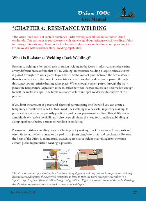
Resistancewelding,oftencalledtackorfusionweldinginthejewelryindustry,takesplaceusingaverydifferentprocessfromthatofTIGwelding.Inresistanceweldingalargeelectricalcurrentispassedthroughtwoworkpiecestojointhem.Atthecontactpointbetweenthetwomaterialsthere is a resistance to the flow of the electrical current. As electrical current is passed through this contact point resistive heating takes place. When enough current passes through the work piecesthetemperature(especiallyattheinterfacebetweenthetwopieces)canbecomehotenoughto melt the metal in a spot. The terms resistance welder and spot welder are descriptive of this process.
If you limit the amount of power and electrical current going into the weld you can create a temporaryorweakweldcalleda“tack”weld.Tackweldingisveryusefulinjewelrymaking.Itprovides the ability to temporarily position a part before permanent welding. This ability opens a multitude of creative possibilities. It also helps eliminate the need for complicated binding or clamping of parts before permanent welding or soldering.
Permanentresistanceweldingisalsousefulinjewelrymaking.TheOrioncanweldearpostsandwires,tietacks,catches,domedordappedparts,jointspins,bolobacksandmuchmore.Becausethe heart of the Orion is an industrial capacitive resistance welder, everything from one time custom pieces to production welding is possible.
“Tack” or resistance spot welding is a fundamentally different welding process from pulse arc welding. Resistance welding uses the electrical resistance to heat to fuse the work piece parts together in a “spot”. Left: A typical (industrial) welding configuration. Right: A close-up zoom of the weld showing the electrical resistances that are used to create the weld spot.

Orion 100C
User Manual
www.OrionWelders.com28
As shown in the figure above, a typical weld configuration requires a positive and negative electrode with pressure applied to the work piece parts. As we zoom in on a cross sectional view of the work piece parts, we can identify the electrical resistance locations where heat is generated. For fine spot, or small scale resistance welding, most of the heat is generated at the contact point between the two work pieces. This has been identified on the figure as the largest resistance point. Duringtheweldalargepulseofelectricalcurrentisdumpedquicklythroughtheworkpiececausing rapid heating and melting at the electrode location.
During the weld a large pulse of electrical current is dumped quickly through the work piece causing rapid heating and melting at the electrode location.
Left: On the micro scale all surfaces have a degree of surface roughness. This roughness causes the work pieces to only contact in a limited number of locations. Middle: Applying more pressure will
cause more surface contact, less resistance and less resistive heating. Right: Applying less pressure will cause less surface contact, more resistance and more resistive heating.
Duringaresistanceweldthesurfacebetweenthetwopartsbeingweldedisnottrulyflat.Onthe micro scale these surfaces are rough and only contact in a limited number of locations and the limited contact translates to an increased electrical resistance at the contact between the two parts. A resistance welder uses the resistance to the flow of electricity to heat and melt the part via alargeelectricalcurrent.Thiscontactpointiswherethehighestheatisgenerated.Lightpressurebetween the parts means less contact between the two surfaces, more resistance, and hence more heatingandmelting.Heavypressurebetweenthepartstranslatestomorecontactbetweenthetwosurfaces, less resistance, and less heating.

Orion 100C
User Manual
1-877-786-9353 29
For small scale welding the melting processes typically will start at the interface between the two parts due to this high contact resistance. The exception to this rule is when resistance welding conductivematerials(copper,silver,gold,brass)thatrequireatungstenormolybdenumelectrode.Whenweldingwitharesistiveelectrode(tungsten)theheatingactuallytakesplaceattheinterfacebetween the electrode and the part.
Left: Resistance welding using a series electrode configuration. Middle: Resistance welding using
a step electrode configuration. Right: Resistance welding using an opposed or direct electrode configuration.
When resistance welding conductive materials like copper, gold and silver, the electrode in contact
with the conductive material must be Tungsten or Moly. The melting then takes place from the electrode and works toward the part interface.
Left: Weldments (weld protrusions or bumps) can be used to focus the weld energy when resistance welding difficult materials or larger parts. Right: Weldments force the current to travel through a
smaller area create more heat at that location.
Sometimes it can be helpful to focus the energy of a resistance weld for larger parts. This can

Orion 100C
User Manual
www.OrionWelders.com30
be done by using a weldment, or bump between the parts to be welded. This bump forces the electricalcurrenttopassthroughaconcentratedpoint(especiallyimportantforthickerparts).The smaller the bump tip diameter the more heat that can be generated at that point. This technique is also very helpful for welding dissimilar, conductive metals. For example, resistance weldingsilvertogoldcanbedifficult,however,ifIplaceagoldweldmentonthesilverpartthegold to gold resistance weld become very simple.
To aid in resistance welding difficult thicknesses or material combinations. 1.) Place a weldment or bump on one side to focus the energy. 2.) Use an electrode configuration that is simple and have as
much contact area as possible on the outside of the parts. 3.) The weldment or bump will fuse into the other part making a resistance weld that cannot be seen on an edge.
Tips When Resistance Welding
With the above in mind there are several different helpful recommendations to use when resistance welding.
1.Thepressurebetweenthetwopartsisthemostimportantvariableinresistancewelding;eventheamountofpowerbeingusedfortheweldplays(toadegree)alesserrole.
2.Highpressurewillcreateacoolweld.3.Lightpressurewillcreateahotweld.4.Nopressurewillproduceanarc!!5.Placingasmallbumporweldmentbetweendifficulttoweldpartscansimplifythewelding
process.
If using tools to hold the work pieces remember that firm pressure between the tool and the work piece is important to prevent welding thetooltotheworkpiece(e.g.brasslinedpliers).Thenapplythecorrect pressure between the work pieces to achieve your weld.
The pressure between the tool holding the part is also very important.Ifinsufficientpressureisappliedbetweenthetooland

Orion 100C
User Manual
1-877-786-9353 31
the part the weld may take place between the tool and the part. Always grip the part firmly in the tooltoreducethecontactresistancebetweenthetoolandworkpiece.Doingthiswillreducetheamount of heat created where the tool and part meet.
Resistance Welding Tools
It is always a good idea to have the resistance welding tool made from a material like copper (whenweldingmoreresistivepartssuchassteels).Ifusingatooltoholdtheworkpiecetogetherremember that firm pressure between the tool and the work piece is important to prevent welding thetooltotheworkpiece(e.g.brasslinedpliers).Thenapplythecorrectpressurebetweenthework pieces to achieve your weld. This will help to ensure the resistance between the tool and the part is very low and no weld is made at this location. Typically, it is not good practice to use a set of steel pliers to hold a steel part, for example, during resistance welding. The tool can easily fuse to the work piece.
Typically, steel is not used for resistance welding because of steel’s high internal resistance. This high resistance means that a great deal of power is dropped in the tool before even making it to the weld location. The exception to making a resistance welding tool from steel is when only a small amount of power is needed. This may happen when only a light tack weld is needed before pulse arc welding.
Cables for Resistance Welding
A true resistance welding hand piece should transfer as much power to the weld location as possible. The Orion is capable of transferring over 3000 amperes to the weld location. To enable this full power transfer:
1.Theweldingattachmentshoulduse3.5ft(~1m)of10AWGcable.2.IMPORTANTthecableshouldbenolargerthan10AWGordamagetotheweldermay
occur(e.g.8AWGisalargercable).
Notalltackweldsrequirethisamountofenergy.Smallercabledpulsearcattachmentscanbeusedfor simple tack welds that require lower power.
Custom Resistance Welding Tools
Itmaybehelpfultoshapethetoolfortheapplication.Toolsthatclamptheparts(e.g.brasslinedpliers)shouldhaveasmuchsurfaceaspossibleincontactwiththeparttoallowmorepowerto

Orion 100C
User Manual
www.OrionWelders.com32
transfer to the weld location. Remember that the area between the work pieces should be small to focus the energy if a strong weld is desired. A weldment or bump can be used to help focus the energy if desired.If you are shaping an electrode to actually perform the weld then the tip should be as small as is reasonableforthedesiredweldsize(e.g.1mmspotsizeorlessistypical).Rememberthatwhenusing an electrode to perform the welding process, the pressure applied by the electrode tip determines the weld pressure and the heat generated. A weldment or bump between the two parts to be welded can still be used to focus the energy. Place the electrode directly over the weldment location(remembertheweldmentisactuallybetweenthetwosheetsetc,notontheelectrode).
CHAPTER 5: TUNGSTEN ELECTRODESTHESINGLEMOSTIMPORTANTVARIABLEINTHEWELDINGPROCESSISTHEELECTRODE.TheOrionweldercomesstandardwith(5)0.5mmand(5)1.0mmelectrodes.The 1.0mm electrodes are a good all around electrode while the 0.5mm electrode is excellent for verysmallprojects.Thelarger1mmelectrodeallowsmoreenergytocomeoutatonetime.Thesmaller 0.5mm electrode may be better for cases when less energy is desired.
HANDS ON: Make a weld using pulse arc-mode at 15 Joules and 8ms using a sharp 1.0mm electrode. Now make a weld using the same settings using a sharp 0.5mm tip.
Inthe‘HANDSON’examplesabove,morepowerwastransferredfromtheOrionintothepiecefor the same setting using the 1mm electrode. For very small parts using the small electrode is sufficient.Thisoptionreducesthepeakweldcurrentversususingthelargeelectrodeandcanalsoallow for a smaller weld spot. For larger parts use the 1mm electrode. The 1mm electrode is used whenneedingadditionalweldcurrent(moremeltingforsameenergy).Thelargerelectrodeisrecommended for metals such as silver, due to higher welding energy requirements of such metals.
Please note that the 1mm electrode should be used for the normal pulse arc welding mode and the 0.5mmsmallelectrodewill“burn”oroxidizeathigherpowersettings.Asageneralsuggestion,the 1mm electrode is a good choice for most applications, even very small ones.

Orion 100C
User Manual
1-877-786-9353 33
Left: Using too much power with the 0.5mm electrode will cause it to overheat and reduce its life. Right: A 1.0mm electrode can weld at a variety of powers without overheating.
Why Use Tungsten Electrodes?
1.Hardness–tungstenisextremelyhardandisthereforeabletoholditsshapeduringthewelding process.
2. Tungsten’s melting temperature is much higher than most other metals. This means the metals being welded will melt before the tungsten.
Melting temperatures of selected metals:
Material MeltingPoint(degC)
Zinc 420
Aluminum 660
Silver 962
Gold 1064
Copper 1083
Stainless 304 1450
Carbon Steel 1500
Titanium 1660
Platinum 1772
Niobium 2468
Tungsten 3410

Orion 100C
User Manual
www.OrionWelders.com34
Thetableshowsavarietyofmetalsandtheircorrespondingmeltingtemperatures.Notethat tungsten has a significantly higher melting temperature than the other metals. This is an important attribute of tungsten that aids the welding process. While welding, electrons from the weld plasma impact the work piece and form a weld spot. At the same time, positively charged gas atomsimpacttheelectrode.Bothoftheseprocessescreateheat.However,moreheatisgeneratedby the electrons impacting the work piece than the atoms striking the electrode.
Electrode Shape
The electrode shape is a very important aspect to consider and has a significant impact when welding various metals. The shape of the electrode will greatly affect the welding plasma created during the arc. Poor electrode shape will lead to plasma arcs that are not repeatable while good electrode shape will help the plasma arc to discharge smoothly from the welding tip.
The grinding direction to sharpen the electrode is very important. When grinding, make sure that grind marks run parallel to the electrode shaft. Parallel grind marks will allow the plasma to dischargeuniformlyandsmoothlyfromtheelectrode.Grindingtheelectrodesuchthatcircularrings or marks show up will lead to a poor plasma arc, affecting weld quality. The plasma will discharge inconsistently from the electrode ridges and may become unstable, oscillating in time. The weld spot will not be repeatable.
Grind marks on the electrode should always run parallel to the length of the electrode.
The arc will be unstable in time and the weld spot will not be repeatable if grind marks are circular.
As a rule of thumb the electrode should be ground so that the taper is approximately 2.5x the diameter. The resulting electrode shape is a good general shape for easy arc ignition and excellent weld spots.

Orion 100C
User Manual
1-877-786-9353 35
Always grind the welding electrode so that grind marks run parallel to the electrode shaft. Placing the electrode incorrectly on the diamond wheel will produce circular grind marks and poor weld results.
HANDS ON: Grind your electrode so that grind marks run parallel to the electrode shaft. Verify by looking under the microscope. Try to produce a taper that is approximately 2.5x the electrode diameter.
Electrode Shaping Effects
There are two main electrode shape configurations that Orion users should consider when preparingforanewproject.Thefirstisthesharpelectrode,whichisthebestformostapplicationsand metals. A sharp electrode is also the easiest to ignite and typically produces a good weld spot. A sharp electrode is especially important for small parts where fine control is essential.
The second electrode shape is a flat ended tip. This tip helps spread the energy more uniformly andisbettersuitedfordifficultmetalslikesilver.Acombinationofapointedelectrodewithasmall flat tip can also be useful for a variety of metals. This configuration will help improve arc propertiesforsilver(andlikemetals)whilestillallowingsmallerpartstobewelded.
As a general rule of thumb you can think of a sharp tip as a weld focuser while a blunted or truncated tip is a weld un-focuser.

Orion 100C
User Manual
www.OrionWelders.com36
The shape of the electrode will influence the shape and penetration of the weld spot. There are advantages and disadvantages to each electrode shape.
As shown in the illustration above, the electrode shape greatly influences the weld spot’s shape andpenetration.Bylookingatthefigure,onemightassumethatthe180degreeshapeisthebestelectrodeconfigurationtoachieveanoptimalweldspot.However,the15degreeelectrodeshapehas the advantage of easy weld ignition at lower power levels. In some situations it is advantageous toplaceasmallflatontheendofthesharpertip–ortruncatetheweldtip.Thishasastabilizingeffectonthearcandalsoallowsdeeperweldpenetration.Evenasmallflatonanotherwisesharpelectrode can be helpful in making repeatable welds while still allowing easy arc ignition. For the smaller energy settings an extremely sharp electrode is essential. Remember the size of the truncationflatisrelatedtothepowersetting.Usesmallerflatsforlowerenergy–largerflatsforhigh energy.Thereareseveralconsiderationsthatcanbehelpfulwhenselectingelectrodeshape(e.g.sharp,blunt,orasharptipwithasmallflattedend).ThemosthelpfuloftheseistospendtimewiththeOrion and get to know how it responds to different electrode shapes and metals.
Considerations for Electrode Shape:
1. When welding very small features, under about 1mm, the electrode should be sharp to help focus the weld energy.
2. When welding in with less than 20-30 Joules the electrode will typically be sharp.3.Somematerialsweldbetterwithasharpelectrode(e.g.StainlessSteel).4. When welding at very low power settings a sharp electrode will help ignite the arc more easily.
The tip shape changes the energy focus and weld penetration. The weld spot on the left was formed with a blunt electrode, while the spot on the right was made using a sharp electrode.

Orion 100C
User Manual
1-877-786-9353 37
5. Flattened tips provides arc stability at higher energies6. At high energies a sharp tip may melt off during the welding process and contaminate the
work piece.7.Alargeflatorcompletelybluntelectrodetipforsomemetalsisdesirable(e.g.silver,
aluminum).8. A large flat can be helpful on all metals depending on the desired weld puddle and the work
piece geometry.9.Truncatingtheelectrodehelpstoun-focustheweldenergyandprevents“burrowing”in
mobile metals like silver.10.Howlargeyoumakethetipflat(e.g.averysmallflatvs.acompletelybluntelectrode)is
determined by the amount of power the Orion will deliver. At low energies no flat is needed, whereatmaximumenergythetipcan(ifdesired)becompletelyblunt.Remember,thesmaller the flat the easier the weld ignition.
A blunt electrode tip can be helpful when making more powerful welds in silver to help overcome silver’s high liquid mobility by “un-focusing” the plasma over the entire flatted area.
A sharp electrode will help place the weld into tight geometries (left), a blunt electrode can spread the energy and prevent weld formation (right).
Asdiscussedabove,silverisreallythemajorexceptiontohavingasharptip.Becauseofsilver’shighliquidmobility,asharpelectrodewithafocusedarc(attheverytip)willactuallyburrowaholeinthecenteroftheweldspotathigherenergies.However,forsmallspotsasharptipisstillrecommended in silver. When welding with higher energy settings the users will find that a sharp tipwillactuallydigaholeinalargepieceofsilverorforthinnersilver,createahole.Byusingablunted or truncated tip the energy is effectively spread over the weld area and both the burrowing hole and the thin silver blow-through can be largely avoided.

Orion 100C
User Manual
www.OrionWelders.com38
Troubleshooting the Electrode
Poorweldresultsaremostoftentracedbacktoelectrodeconditionandshape.Becausetheelectrode condition is very important, the following table will help troubleshoot problems quickly.
Symptom Possible Problem Possible Solution1 Trouble igniting the arc Contaminated electrode Re-grind the electrode to
remove contamination
2 Electrodeshapenotconducive to ignition at low energy
Shape the electrode to a very sharp tip
3 Brokenelectrode,jaggededges
Re-grind electrode to desired shape
4 Cratering of the weld spot
Electrodecontaminationleading to a metal bridge explosion(seediscus-sion)
Re-grind the electrode
5 Sharp electrode in a mo-bile metal such as silver
Truncate the end of the electrode to help “un-focus”theweldenergy
6 Weld spot not symmetric Damagedorjaggedelectrode
Re-grind electrode
7 Porosity in the work piece
Damagedelectrodewithjaggedtips
Re-grind electrode
8 Metal may contain zinc and“boil”duringtheweldingprocess.(e.g.whitegold)
Often welding over the same location two or three times will smooth the weld spot
9 Sharp electrode in a mo-bile metal such as silver
Truncate the end of the electrode to help “un-focus”theweldenergy
In the table above we see that trouble igniting the arc can be cause by several different reasons. The most common is a contaminated electrode. If the work piece metal contaminates the welding electrode the following may occur:
1.Duringtheignitionprocesstheelectrodeistouchingtheworkpiecesurfacewhentheweld current begins to flow. The metal contaminate may form a liquid metal electrical

Orion 100C
User Manual
1-877-786-9353 39
conductionbridge.Duringtheweldignitionprocesstheelectrodewillretractandthismay lead to the vaporization of the liquid metal bridge as it is necked down during the electroderetractionprocess.Thisvaporizationprocesscanbeexplosive(onaverysmallscale)andleavesacraterinthemetal’ssurface.Theresultwillbeasmall“pock”markinthe metal’s surface. The electrode must be reground before reliable welding can continue at thissetting.Atlowerenergies(e.g.micromodeat20%power)thisresurfacing/re-tippingmay be very important to get the welder to ignite reliably. At higher energies the welding process may proceed virtually unhindered even with a metal contaminated electrode. To remove the small crater, weld over the crater with a newly ground electrode.
2. The electrode may stick to the metal’s surface. This happens as the liquid metal bridge cools beforetheelectrodetiphasretractedsufficientlytoleavethesurfaceoftheworkpiece.Anow solid metal to metal weld has taken place at the electrode tip preventing retraction and arcignition.Thisisoftenreferredtoaselectrode“sticking”.
3.Whatcanbedoneiftheweldspotdoesn’tlookgood,asymmetricforexample?Thismaymeantheelectrodemaybedamaged(sharptipsorjaggededgesorstrangeshapeduetocontamination).Poortipconditioncanalsoleadtoporosity(smallholesintheworkpiece).
Electrode contamination can lead to small “explosions” that create craters in the work piece. All four welds were made at the same setting. Metal contamination on the electrode caused one weld to create a crater.
Itisrecommendedthattheuserpaycloseattentiontotheelectrodecondition(seeadditionaldiscussion).Acontaminatedelectrodecanleadtoinconsistentweldsandpoorarcstarting.Onlylight pressure is needed to start the welding process, too much pressure will interfere with the welding process, lead to electrode metal contamination and will shorten the amount of time you can weld before re-sharpening or replacing the electrode.
Electrode condition greatly affects power transfer and also weld properties (see above discussions). Left: A perfect electrode. Right: An electrode in poor condition with metal contamination.

Orion 100C
User Manual
www.OrionWelders.com40
CHAPTER 6: METALS
Weldability of Common Metals
One very important aspect of Pulse Arc welding is a working knowledge of material properties. This knowledge will help you understand why various metals will react differently during the welding process. Shown below is a table of properties of some common metals. These metals have beenarrangedbymeltingtemperatureforconvenience.Eachofthepropertieslistedbelowwillhave an effect of the weldability of the metals.
Zin
c
Alu
min
um
Silv
er
Gol
d
Cop
per
Palla
dium
*
Cob
alt C
hrom
e*
Stai
nles
s 304
*
Car
bon
Stee
l
Tita
nium
Plat
inum
Nio
bium
Tung
sten
Melting Point
420 660 962 1064 1083 1200 1300 1450 1500 1660 1772 2468 3410
Boiling Point 607 2467 2212 3080 2567 3100 2800 3000 3000 3287 3827 4742 5660
Specific Heat
388 900 237 129 385 244 10 500 500 523 129 268 133
Electrical Resistivity
6 2.7 1.6 2.2 10.6 10.8 475 70 60 54 10.6 16 5.4
Density 7.1 2.7 10.5 19.3 9 11 8.3 7.9 7.8 4.5 21.5 8.6 19.3
Thermal Expansion
31 23.5 19.1 14.1 17 11 10 18 12 8.9 9 7.2 4.5
Thermal Conductivity
116 237 429 318 401 71 100 16.3 50 22 71.6 54 173
*Some Values may be approximate
Melting Point: The temperature at which the metal will begin to melt. The molten metal of the weld pool will be at this temperature during the welding process.
Boiling Point: Ifenoughenergyisaddedtotheweldjoint(andheatisremovedslowlybythesurroundingsolidmetal)theweldpuddlecanbegintoboil.Liquidmetalwillbeturnedinto gaseous metal.

Orion 100C
User Manual
1-877-786-9353 41
Specific Heat:Theenergyrequiredtoraisethetemperatureofthemetal(perunitmass).Thinkofthisnumberashowmuchmetalwillmeltforagivenweldenergy(meltingpointalsoisimportant).Alargerspecificheatmeansmoreenergyisrequiredtomeltthemetal.
Electrical Resistivity: This number represents the resistance to the flow of electrons in a metal.Thispropertyisespeciallyimportantduringaresistanceor“tack”weld.Themoreresistivethemetalisthemoreeasilyitwillresistanceweld(e.g.stainlesssteels),thesmallerthisnumberisthemoredifficultitwillbetoweldthematerial(e.g.silver),especiallyin“tack”mode.
Density:howmuchofthemetal(atoms/mass)isinagivenvolumeofspace.Thispropertywill also influence how large the weld spot is for a given metal. All other things being equal, a lower density metal will have a larger weld spot than a higher density metal for the same weld energy.
Thermal Expansion: When a metal is heated it will expand, or elongate slightly. In some situations, especially during resistance welding, metal can expand quickly and spill out of theweldjoint.
Thermal Conductivity: This is a measure of how fast the metal conducts heat. Metals that aregoodconductorsofheat(e.g.copper)willdispeltheheatawayfromtheweldlocationquickly during the welding process. This action reduces the size of the weld spot. Metals thatarepoorconductorsofheat(e.g.titanium)areslowtoconductheatawayfromtheweld location and the weld energy has a greater affect on the weld size, etc.
This measure of weldability comes from properties of the metal like melting point, thermal conductivity, density etc., and is intended as a relative reference between the different metals. It can be thought of as how much spot size and penetration a given amount of weld power will have on the metal. Please note that some metals may have properties not accounted for in this chart that may
make welding more difficult than indicated (e.g. palladium).

Orion 100C
User Manual
www.OrionWelders.com42
Titanium and Niobium
Somemetalsmayreacteasilywithoxygenandevenothergaseslikenitrogen.Titanium(Ti)reactswithbothoxygenandnitrogenatelevatedtemperatures.(Ti)burnstoform(TiO2)inairat1200degC.(Ti)willalsoburninpure(N2)gasat800degCtoform(TiN).Titaniumnitride(TiN)isinherentlybrittle,whichwillresultinaweakweldjoint.Verylightreaction(mostlyshielded)mayjustincludeslightdiscoloration.However,aheavyreactionwillcauseabsorptionofgas and will cause a dark gray and porous result. If the reaction is too heavy the weld location will become very weak and porous. Niobium(Nb)reactswithbothoxygen(O2)andnitrogen(N2)gas.Niobiumwilloxidize(reactwithoxygen)at200degC.Thereactionwith(N2)startsat400degC.Asyoucansee,niobiumisevenmorereactivethantitanium.Thismeansthatgreatercaremustbetakenwhenwelding(Nb)toensurepropergasshieldingandcleanwelds.Forthinpartsthisisparticularlydifficultasheatiseasilyconductedtotheoppositeweldside(theundersideofthesheetforexample).Thisheatontheundersidecausesthe(Nb)toabsorb(O2)and(N2)gasesresultinginbrittlewelds.
Forboth(Ti)and(Nb)thelevelofoxidationcanbeobservedvisually.Heavyoxidationwillcauseagrayporoussurface,however,oxidation(ornitrogenabsorption)insmallerdegreeswillcausethesurfaceofthemetaltocolor.Thisprinciplecanbeusedtoactually“paint”onoxideindifferentcolorson(Ti)and(Nb)parts.
Titanium and Niobium metals will oxidize readily at elevated temperatures and voltages. The charts show (Ti) and (Nb) “painting” with electricity (showing the voltage at which the color will appear). However, similar colors will appear due to heat if welding without sufficient shield gas. These colors
during welding need to be avoided. (Picture courtesy of Reactive Metals)

Orion 100C
User Manual
1-877-786-9353 43
Howtoavoidoxideandnitrideformation(thesewillworkforothermetalsaswell):Inmanysituationsthisisnotanissuebecausetheargon(Ar)comingfromtheweldingstyluscompletelycoversthemoltenweldpool.However,insomesituationsthisisnotthecase.Forexample,welding on a thin material, the back of the material is unshielded from oxygen and the exposed metal will react with oxygen.
Using the following can help reduce oxide formation on the back of the work piece:
1. Argon flood on both sides of the work piece during the welding process. This is the best method but can use a lot of gas and requires additional setup.
2. Solder flux: A thick layer of solder flux can help reduce oxide formation. Place the flux on the back side of the work piece. The flux should be as viscous and thick as possible. Some fluxes may work better than others.
After saying all of the above, it should be noted that titanium is very simple to weld. With proper gas shielding, the weld looks bright and clean. Titanium to titanium welds are simple to perform andarestrong.Titaniumweldedtoothermetalscanhaveavarietyofresults.Forexample(Ti)toGold(Au)resultsinacleanlookingbutbrittleweld.Copperto(Ti)hassimilarresults.Silverto(Ti)isrelativelystrong.Whenwelding(Ti)toothermaterialsremembertotesttheweldstrengthwith scrap pieces before welding the final work piece.
Oneimportantconsiderationwhenwelding(Nb)isit’shighboilingtemperature(4742degC)relativetotungsten’smeltingtemperature(3410degC).Whatthismeans:ifthetungstenelectrodeiscontaminatedwith(Nb)metalthe(Nb)metalmaysuperheatandstarttoboilrightontheelectrode.Thisboilingofthe(Nb)willinturnmeltthetungstenelectrodecausingittoloseitssharp shape.
Yellow / White Gold (Au)
Yellow gold is a relatively simple material to weld. Typically, it will produce a strong and symmetric weld spot and resulting welds are smooth and require little cleanup. This is true for evenlowerKaratgolds;however,pleasenotethatweldresultswillimprovewithhighergoldcontent. Typically, the different metals added to gold are used to change its wear characteristics andcolor.Themoreadditionalmetaladded(notgold)thelowerthekaratvalue.Lowerkaratgolds that contain copper and silver, etc. can produce a black coating around the weld’s surface. This can easily be steam cleaned, wiped off with a clean rag, or taken off with a glass brush. Please also note that sometimes during the welding process a small amount of the welded metalwillevaporate.Differentmetalswillevaporateatdifferentratesfromtheweldpool.The

Orion 100C
User Manual
www.OrionWelders.com44
evaporated metal can deposit around the weld location in a very thin layer that can look black. This type of deposit can typically be removed by steam cleaning, wiping with a clean rag or with a glass brush.
Pleasealsonotethatsomegoldalloyscancontainsmallamountsofzinc(0.5-1.0%).Thiszincaddition is used as a deoxidizer during casting, and can improve the fluidity of the molten metal. As discussed above, zinc can cause porosity and will contribute to a black film that must be removed via glass brush or clean rag.
Yellowgoldphysicalpropertiesandcomposition(onepossible):58-75% gold, 12-27% silver, 9-15% copper and some zinc
White Gold: White gold is also a relatively simple metal to work with. There are two main types ofwhitegolds–palladium-whitegoldandnickel-whitegold.
Palladium–whitegoldcomposition(onepossible):58.5%gold,10%palladium,28.5%silver,2.5%(copper,nickel,zinc)
Nickel–whitegoldcomposition14k(onepossible):58.5% gold, 25.8 % copper, 15.3% nickel, 0.4% zincGoldcolorcanbechangedwiththefollowingalloying(showalloychartbycompositionandcolor)
Notethezinccontentofwhitegold.Highzinccontentcanleadtowelddefectslikeporosity,etc.asthezincboilsoutoftheweldjoint.Pleaseseethepreviousdiscussiononovercomingporosity.In short, welding over the location with porosity again will help remove the porosity. A fresh, sharp electrode will help with this process. Sometimes adding pure laser wire will also help in removing porosity.
Ingeneral,goldweldseasily.Herearesometipswhenworkingwithgold:
1. Typically a sharp electrode is preferred when welding gold.2. Goldcaneasilyacceptsmallorlargeweldspots3. It is often typical that gold will look black surrounding the weld location. This black layer
is easily removed with steam cleaning, clean rag, or a small glass brush.4. Goldcaneasilybeaddedtoalmostanyothermetal.5. Very interesting welding combinations are possible.

Orion 100C
User Manual
1-877-786-9353 45
Platinum (Pt)
Platinum(Pt)hasameltingtemperaturethatissimilartostainlesssteel,butadensitythatis3timeshigher.Inaddition,thespecificheatof(Pt)islowerbyafactorof4thanstainlesssteel.Thismeansthatittakeslessenergytoraisethetemperatureof(Pt)toitsmeltingtemperature.Theendresultisthat(Pt)isalittlemoredifficultthanstainlesssteeltoweldbutverysimilarinoverallbehavior.
Oneimportantconsiderationwhenwelding(Pt)isitshighboilingtemperature(3827degC)relativetotungsten’smeltingtemperature(3410degC).Whatthismeans:ifthetungstenelectrodeiscontaminatedwith(Pt)metalthe(Pt)metalmaysuperheatandstarttoboilrightontheelectrode.Thisboilingofthe(Pt)willinturnmeltthetungstenelectrodecausingittoloseitssharp shape.
Palladium (Pd)
Palladium(Pd)isawhitelustrousmetalthatistypicallyamuchlowercostthanplatinum.Palladiumisalsomuchlighter,havingadensity½thatofplatinum.Itwouldseemthat(Pd)istheperfectmetal.Unfortunately,(Pd)isgenerallydifficulttoworkwithandissomewhatdifficulttoweldinajewelrysetting.Thisismainlyduetopalladiumcrackingduringtheweldingprocess.
Palladium can be welded using the Orion welder, however, cracking can occur.Palladiumcrackingisanespeciallydifficultphenomenontoovercomewithlaserorpulsearcwelding.Ifonlyoneweldspotismade,crackingwilltypicallynotoccurunlesstheweldjointisstressedbyhammering,etc.Thismeansthatweldingoverporosityina(Pd)piececanbeaccomplishedwiththeOriontohelpcleanupthemetalduringthefinishingprocess.However,weldingmorethanoneoverlappingweldwillinevitablyleadtocracking(laserorpulsearcwelder).Palladium cracking can be thought of as a combination of hot cracking and new weld puddle crystalstructureproblems.Afteraweld,themolten(Pd)re-crystallizes,typicallyformingalargeand weak metal grain structure. When welds overlap, the new crystal structure in the last weld puddle is weak compared to the original metal. The result - a crack will start at the edge of the newweldwhereitoverlapswiththeoldweldjointasthenewweldcoolsandisstressed.Thecrackwillthenrunalongthemiddleoftheweldpuddleinthedirectionoftheoverlappingjoints.Thiscracking is due to the stresses created during the weld puddle cooling process as described above withhotcracking.However,thistimeinsteadofgeometrycausingthecracking,aripstartsinthe old crystal structure and propagates during the cooling process, much like ripping a piece of

Orion 100C
User Manual
www.OrionWelders.com46
paper.Theresult–(Pd)isdifficulttoweldsuccessfullywithoutbreakage.Typically,singlespotsofporosity can be welded and fixed but overlapping welds will crack.
There is a welding solution that can stop this cracking process. The addition of gold fill wire to theweldjointcreatesanewalloyandstrongercrystalstructure.Thegoldcandiscolortheweldjoint.However,byweldingoverthejointseveraltimesthegoldwilldiffuseintothe(Pd).Anotherpossiblesolutionistouseahighgoldcontentwhite-gold(Pd)alloylaserwire.
Silver (Ag)
Silver is an interesting metal with several properties that must be considered during the welding process. First, silver is highly reflective over a large range of light wavelengths. This metal characteristicmakesweldingsilverdifficultforalaser,butposesnoproblemsforaPulseArcwelder. Second, silver is a very mobile metal when in a liquid state and has low surface tension whencomparedtoothermetals.Becauseoftheseproperties,howtheweldenergyisappliedtosilver is important.When welding silver it is important to understand the concentration of your weld energy relative to the size of the silver being welded. For very small welds, a sharp electrode poses no problem. This means that in the Orion’s micro mode, silver will typically behave well even with aconcentrated,focusedbeamofenergy(i.e.averysharpelectrodetippoint).However,asthedesiredspotsizegetslarger(biggermicromodeweldsandalmostallpulsearcmodewelds)theliquid silver is easily pushed around by the welding pulse. This will lead to large blobs of material being displaced from the weld site resulting in a noticeable hole. To avoid this problem, simply un-focus the weld energy by creating a truncated electrode tip flat. The size of the flat depends on the size of the weld. For relatively small welds a small flat is all that is required. For very high energyweldstheelectrodemaybecompletelyflat(1mmdiameter).
Resistanceweldingsilverintackmodeisverydifficultbecauseofsilver’shighelectricalconductivity(tackmodeisnotontheOrion100c,callformoreinformationaboutthisfeature).Sterlingsilverhasahighelectricalconductivityverysimilartothatofcopper.However,Argentium silver is approximately 30% less conductive. This means that more heat can be generated during the spot welding process due to the additional material resistance. Use Argentiumsilverifyourapplicationrequiresspotweldingasopposedtopulsearcwelding.Evenwhile pulse arc welding it may be desirable to use Argentium silver because of its superior tarnish resistance. Thin Argentium silver parts can be welded directly using copper electrodes. Thicker silverpartsmayrequireaweldprojectionor“bump”tofocustheweldcurrent.Thisweldingstrategy is discussed in detail in Chapter 4 - Tack Welding.

Orion 100C
User Manual
1-877-786-9353 47
Aluminum (Al)
Aluminum behaves very much like silver during the pulse arc welding process. Aluminum has a verylowmeltingtemperature(660degC)andisverymobilewheninaliquidphase.Thismeansthat the same principles that apply to welding silver also apply to Aluminum. Aluminum also hasoneadditionalcomplicationthatmaymakeitdifficulttoworkwithinsomesituations.Thismetal is very susceptible to hot cracking. On occasion the weld parameters or geometry may be such that a crack may appear in the weld. Always perform test welds for strength verification. In general, pulse arc welding in aluminum will produce a weaker weld than with other metals.
Stainless Steel
Stainlesssteelsarerelativelysimpletoweld.Theweldpuddlelookssmoothandjoinseasilyandtheresultingweldjointisstrong.Becauseofthelowthermalconductivityofstainlesssteel,itiseasy to hold the work piece in hand while welding without weld heat immediately making the work piece too hot to hold. Use only stainless steel fill wire when welding. If regular low carbon steelisused,theweldjointwilleventuallyrustovertime.
Austeniticstainlesssteels,(304forexample)weldeasily.However,hotcrackingisapossibilitywith this material. To help avoid any cracking it is helpful to weld using an alloy that will produce asmallamountofferriticcrystalstructureintheweldjoint.Theadditionoftheferriticcrystalstructure will help suppress cracking. For example, when welding 304 stainless, a 308 stainless fill wirecanbeused.Notallsituationswillrequirecracksuppressiontechniques.Smallerparts,likethosetypicallyweldedusingtheOrion,donotrequiretheseprocedures.(201,202,205,216,301,302, 303, 304, 305, 308, 309, 310, 312, 314, 316, 317, 321, 329, 330, 332, 347, 348, 384, 385 stainless steels).
Martensiticstainlesssteels(410forexample)haveahighcarboncontent.Thishighcarboncontent increases the risk of cracking. To decrease the risk of cracking it may be helpful to increase theworkpiecetemperaturetobetween200–300degC.Oftenmaterialthinnerthan3mmcanbewelded successfully without heat treatment provided that pure argon is used during the welding process.(403,410,414,416,418,420,422,431,440,501,502,503,504stainlesssteels).
Low Carbon Steels (Mild Steel)
Lowcarbonsteelstypicallyweldeasilywithnomajorcautions.Pleasebeadvisedthatlowcarbonsteel will rust and will often come with a coating of zinc. The zinc coating will cause the metal to

Orion 100C
User Manual
www.OrionWelders.com48
appear more white or lustrous than typical steel. As discussed above, welding on zinc will cause many issues to consider. The zinc will evaporate quickly from the weld area causing a black coat tospreadtothesurroundingmetal(includingtheweldingstylus).Thezincevaporationmayalsocause strange weld behavior, etc.
For best results select a low carbon steel without a zinc coating. Make sure the steel is free from other contaminates such as rust or oil. Remember that if using the Orion to produce welds in very thickpiecestheweldjointmayneedtobepreparedasdiscussedpreviously.
High Carbon Steels (Spring Steel / Tool Steel)
Highcarbonsteelweldseasilybutmaybecomebrittleaftertheweldingprocess.Toavoidweldfailure the part must be heat treated after the welding process.
Cobalt Chrome Alloys
CobaltChromeisverysensitivetooxygencontamination.Ifthereisinsufficientargoncoverageoroxygen present in the argon gas this alloy will crack. Once oxygen embrittlement has occurred the weldareamustberemoved(viagrindingetc)topreventfuturecrackingoverthesamearea.
Copper
Copperisoneofthemoredifficultalloystoweldbecauseofitshighheatcapacityandhighthermalconductivity.Thesefactorsmakeitevenmoredifficulttoweldthansilver.Copperalsorequiresmoreenergythansilverfortheweldtotakeplace(about30%more).Thincopper,however,weldsveryeasilyandmicromodeistypicallysufficienttoproduceverystrongwelds.For thicker copper similar techniques as those employed to weld silver must be used.
Brass
Brassisamaterialthatcontainsalargeamountofzinc-30-37%zincbycomposition.Theremaining material is copper.
As discussed previously, zinc is a hard metal to pulse arc weld or resistance weld because of its low meltingandboilingtemperature(420degC,907degC).
Duringthemeltingprocessthelowtemperaturezincevaporates/boilsoutofthebrassalloy.

Orion 100C
User Manual
1-877-786-9353 49
For low energies this simply coats the surrounding material in a black zinc film that can easily be removed with a glass brush.
For larger pulse arc weld energies the black coat can cover larger areas and porosity can develop at the weld location as zinc boils from the weld.
Joining Different Metals
Welding different metals together will produce a new alloy at the weld location. The new alloy will havedifferentproperties(althoughinmanycasessimilarproperties)tothebasemetals.Somemetals combine well, forming a strong and useful new alloy. Other metal combinations are weak and brittle.
HelpfulHintsforCombiningDifferentMetals
1.Checkthenewalloystrengthwithscrapmaterialtoensurethejointwillturnoutasexpected.
2.Youmayneedtoweldoverthejointlocationseveraltimestogetcompletemixingoftheweldpoolandauniformnewalloy.Inmostcasesthisisnotnecessaryforastrongjointandthefirstweldwillbesufficient.
3.Somematerialcombinationsmaybenefitfromathirdmetalatthejointwhichformsabetter/stronger alloy with the two primary metals.
An example of titanium welded to gold and silver. The gold to titanium weld looks clean but is brittle. The silver to titanium weld also looks good and is strong. The Silver to gold weld looks good
and is strong.
Ti
Ag
Au

Orion 100C
User Manual
www.OrionWelders.com50
CHAPTER 7: TECHNIQUES, TIPS, & TRICKS
Pulse Arc Welding: Adding Material
Typicallymaterialisaddedwithasmall“laser”wire,oneweldatatime.However,therearemanyadditionaloptionstoaddmaterial.Forexample,twopartscanbe“tack”weldedinplaceandthenpulsearcweldedforadditionalstability(tackfeatureisnotavailableontheOrion100c,callinfor information on upgrading or trading in your Orion 100c for an Orion welder with the tack feature),orinsteadofusingsmall“laserwire”theOrioncanweldamuchlargerwireorrodtofillin more metal in a single weld. There are several methods to aid in the addition of fill wire, which are mentioned below. The placement of the electrode relative to the wire is very important and will influence how the material behaves during the addition process.
SIDE PLACEMENT: Placing the electrode on the side of the wire is generally the best method of adding fill wire. As show in figure 51 below, place the electrode at an approximate 45 degree angle and at the contact between the wire and the base material. As the electrode pulls away from the base material and the arc ignition happens, the base material will melt first and then the wire will bemeltedandpushedorpulled(bysurfacetension)intothebasematerial.Thisisanexcellentmethod to produce a uniform molten pool of metal and ensure the proper mixing of the base material and the fill wire. The electrode may also be placed at a 45degree angle in front of the wire. However,lessmaterialwillbeaddedwitheveryweld,andaportionofthewirewilltypicallyball-up in the process.
The most effective way to add fill wire to a base material is to place the welding electrode at a 45deg angle from the base surface as shown. Small fill wire will quickly melt into the base material.

Orion 100C
User Manual
1-877-786-9353 51
Remember that for a larger fill wire the energy must be increased to completely melt the wire. If there is insufficient energy there may only be partial melting of the wire. However, in some situations this may be advantageous.
To assist in the welding process, place the electrode tip at a 45deg angle to the wire and part surface. This will allow melting to start at the base and melt the wire into the base as the tip retracts.
HANDS ON: Try adding fill wire using the side placement method. Build up a small mound or material.
TOP PLACEMENT: Placing the welding electrode on the top of the wire will have a much different effect than placement on the base material. With top placement the material addition process will depend a great deal on the wire size and the weld energy. If the wire is very small, the results will be similar to the side placement discussed above. For a small wire welded with high weldenergy(relativetothewiresize)theweldplasmapowersthroughthewire.Thistechniquemeltsthebasemetalandjointsthemeltedwiretothebaseplane.However,ifthewireislargerortheenergyissettoproduceonlyasmallspotsize,thewirewilltypically fail to be added to the base material. Instead the wire will ball and some melting of the basematerialwilloccur,whichisinsufficienttoaddthewire.

Orion 100C
User Manual
www.OrionWelders.com52
Placing the weld electrode on top of the fill wire at a 90deg angle from the base material surface is typically not the preferred method of adding material. If the wire is large compared to the energy
setting, the wire will ball due to surface tension and will not be added to the base material.
A top electrode placement can work if the wire diameter is small compared to the power setting. In this case there is enough plasma pressure to force the molten wire down onto the base material.
A final scenario can occur when the electrode is placed on top of a large wire being welded to a base material at a high weld energy setting. In this case the plasma can push the wire metal down to the base metal surface but there may be no penetration into the base material.
Placement of the electrode directly on top of the fill wire can melt the wire into the base if the power
is sufficient, or the wire is very small. Alternatively it may also only melt the wire causing it to ball as shown for larger wire size or insufficient power settings.

Orion 100C
User Manual
1-877-786-9353 53
HANDS ON: Try adding fill wire using the top placement method. Build up a small mound of material.
As a rule of thumb it is always best to use the side electrode placement. This is especially true of larger fill wire diameters. If it is essential for a top placement weld the process will be improved by using very fine laser wire to ensure full wire melting.
It is important to choose the correct wire size for your application. Extremely small wires may be required for tiny applications; larger wires can be used for things like filling a large joint. The correct wire size will save you time and prevent frustration.
Choosing the correct wire gauge for your application is very important. For example, micro-scale applications, it is important to select the smallest fill wire available. If a wire is selected that is similar in size to the base metal, there is a good chance that the power setting required to melt the wire will also melt the base metal. Alternatively, if the wire is small relative to the base metal, the wire can be melted adding material to the base metal without any damage or warping to the base metal.Forlargerfeatures,selectawiresizethatwillallowyoutoperformyourtaskefficiently.For example, filling a large pore should not be done with ultra-fine wire, but instead with wire of approximately the same diameter as the pore. In this case the repair can be accomplished in literally one weld. In comparison, with the ultra-fine wire, the repair would take many welds.
Pulse Arc Welding: Pushing Metal
There are two competing forces at work during the pulse arc welding process. The first is the surface tension of the molten metal. Surface tension is a force between the metal atoms themselves that is pulling the molten pool of metal flat during the metal’s liquid phase. Metal surface tension(whenmolten)ismanytimesstrongerthanwatersurfacetension.Thesecondforceaswork happens when the weld plasma exerts a force on the molten metal as the plasma’s electrons bombardtheweldsurface.Electronsfromtheplasmawillattempttopushthemoltenmetalinthe direction the electrode tip points. Surface tension and plasma electron pushing are generally competing forces. The plasma tries to push the molten metal, while the surface tension tries to keep it in place.

Orion 100C
User Manual
www.OrionWelders.com54
This means:1.Somemetalswithlowersurfacetension(e.g.silver)areeasierto“push”aroundthanmetals
withhighsurfacetension(e.g.Stainless).2.Surfacetensionitselfcanbeusedtomovemetalsaround.Byplacingtheelectrodebetween
ahighandlowspot,themeltingprocesswilltryand“flatten”thetwo–stealingmaterialfrom the high and moving it toward the low.
The surface tension smoothing is accomplished by placing the electrode at a 90 deg angle from the work piece surface with the electrode tip on the edge or slightly interior to the edge of the metal mound. The welding process will then take material from the mound and spread it into the surrounding material. One should repeat this process until the proper spread of material is achieved.
By placing the electrode between a high and low spot, the melting process will try and “flatten” the two
–taking material from the high area and moving it toward the low area.
Placing the weld electrode on the edge of a bump will smooth away the bump as surface tension spreads the metal over the molten base material.
HANDS ON: Use your electrode with several different materials to push metal around, or to use surface tension to smooth a metal mound out.

Orion 100C
User Manual
1-877-786-9353 55
Please note that various metals will react differently to pushing and surface tension smoothing. For example, silver has a relatively low surface tension while in a liquid state. This means that the plasmapushmethodmaybemoresuccessfulthanitwouldbewithstainlesssteel(withamuchhighersurfacetension).Ontheotherhand,becauseofthehighsurfacetensionofstainlesssteel,the surface tension smoothing method will proceed quickly.
The Orion can be used to push metal around. This is especially helpful if one of the parts to be joined is heat sensitive. In this example the horizontal member is more heat sensitive or is thinner than the
vertical member. Material is pushed from the vertical member onto the horizontal member to prevent part damage.
The Orion can be used to push metal around. This is especially helpful if one of the parts to be joined is heat sensitive. In this example the vertical member is more heat sensitive or is thinner than the horizontal member. Material is pushed from the horizontal member onto the vertical member to
prevent part damage.
Pulse Arc Welding: Weld Cracking
Somematerialsarepronetocrackbecauseoftheirmetalproperties.Forexample,HighCarbonsteel,Palladium(Pd),andsomesilveralloys.Whydoesthecrackingtakeplace?Withsomemetals it is the new crystal structure created during the welding process e.g. palladium and high carbonsteel.However,anothercrackingprocessoftencalled“hotcracking”canoccurwhenthecooling process and the resulting thermal shrinkage create high stresses in the work piece. For

Orion 100C
User Manual
www.OrionWelders.com56
example, some silvers, when first welded, may crack due to the thermal conduction out of the weld puddle.Hotcrackingisverygeometrydependentandcanbeavoidedbycarefullyconsideringtheweldjointbeforewelding.
Questions to consider to prevent hot cracking: 1.Howfastcantheheatescapeandthemoltenpoolcool.2.Doestheheatescapeinapreferentialdirectionthatmayleadtounevenstressesinthe
cooling weld puddle.
Ideas to overcome hot cracking:1.Keepjointgapsassmallaspossible.2.Keepthepulselengthat100%tohelprampdowntheheatmoregradually.3. Pulse Arc Mode has a much longer pulse duration and time that can improve heat ramp
down.
Improper joint preparation or geometry can lead to uneven weld puddle cooling. If the puddle cools in such a way to create a hot center section the hot section will be pulled apart by the stresses from the
cooling out metal.
A proper weld joint will help the weld puddle cool uniformly. This will allow even stresses within the weld puddle and prevent weld cracking.

Orion 100C
User Manual
1-877-786-9353 57
Palladiumandhighcarbonsteelcrackingisaspecialcaseandisdifficulttoovercomewhenlaseror Pulse Arc welding. If only one weld spot is made, cracking will typically not occur unless the weldjointisstressedbyhammeringetc.ThismeansthatweldingoverporosityinaPdpiececanbeaccomplishedwiththeOrion(orlaser)tohelpcleanuparingduringthefinishingprocess.However,weldingmorethanoneoverlappingweldwillinevitablyleadtocracking(laserorPulseArcwelder).
Palladium cracking can be thought of as a combination of hot cracking and a new weld puddle crystal structure problem. After a weld the molten Pd re-crystallizes, typically forming a large and weak metal grain structure. When welds overlap the new crystal structure in the previous weld, the new puddle will be weak compared to the original metal. The result is a crack will start attheedgeofthenewweldwhereitoverlapswiththeoldweldjoint.Thecrackwillthenrunalongthemiddleoftheweldpuddleinthedirectionoftheoverlappingjoints.Thisisduetothestresses created during the weld puddle cooling process as described above with hot cracking. However,thistime,insteadofgeometrycausingcracking,aripstartsintheoldcrystalstructureandpropagatesduringthecoolingprocess,muchlikerippingapieceofpaper.Theresult–Pdisdifficulttoweldsuccessfullywithoutbreakage.Typically,withPd,singlespotsofporositycanbewelded and fixed but overlapping welds will crack.
Heatingadifficultsilverpartcanhelpreducecrackingbyreducingthetemperaturedifferenceduring the weld cooling process. Part heating will change the spot size for a given amount of weldpower.Asthepartgetshot,lessenergyisneededtoproducethesamespotsize.Hence,withoutadjustingtheenergydown,thespotsizewillincrease.Thisisverynoticeableinsilver.Heatingwillalsoreducethehotcrackingapartcanpotentiallyundergo.Theheatingprocessreducesthedifferenceintemperaturebetweenthemetal’sliquidstateandsolidstate(attheheatedtemperature).Thismeansthestressandshrinkagecreatedduringthecoolingoftheweldpuddlewill be significantly less.
Pulse Arc Welding: Joint Preparation
TheOrioncanbeadjustedtoaweldpenetrationofuptoapproximately1mmindepth(dependingonthematerial).However,deeperpenetrationusuallyalsomeanslargespotsizearound3to4mm. When deep penetration is desired but the weld spot size needs to remain small or the work piecethicknessisverythick,additionalweldjointpreparationmaybenecessary. TheYjointisthesimplestjointtoprepare.Usefillwireofanappropriatediametertobuildupmaterialinthejoint.Weldwithnofillmaterialforthefirstpasstoincreasetheweldpenetration

Orion 100C
User Manual
www.OrionWelders.com58
intothejoint.ThenaddfillwiretobuildupmaterialinthetopoftheYuntilthematerialisflushwiththetopsurface.OtherjointpreparationslikeX,V,etc.arepossibleandtheweldingprocedure is similar.
The Y joint is the simplest joint to prepare. First, weld the bottom and top of the work piece without
fill wire to help strengthen the joint. Next, use fill wire of an appropriate diameter to build up material in the joint until the top of the Y is filled.
Other joint preparations, such as X and V, are possible. However, if the materials are thin and butt evenly no joint preparation may be needed.
Pulse Arc Welding: Warping
In some specialized applications, precise positioning of the work piece relative to a model is veryimportant.However,duringthemeltingprocesstheweldpoolwillexpandandshrinkasymmetrically, meaning that the expansion during melting is less than the shrinkage during cooling. This asymmetric expansion can warp the work piece.
The warping can be used to one’s advantage if done correctly. Often the user can simply observe the natural warp in the work piece and place welds to warp the part back into proper alignment. Evenifwarpingisnotdesiredtherearestepstoavoidthisproblem.

Orion 100C
User Manual
1-877-786-9353 59
To do this, start with very small pulse arc weld energies in micro mode. This will minimize the initial warping as you stabilize the work piece. Always alternate sides during the welding process –severalweldsinarowononesidecanexaggeratethewarping,whilealternatingweldswillpullthe part back and forth eliminating most warping. After the smaller stabilizing welds have been placed you can turn up the power and make the larger welds. It is still a good idea to alternate weld sides during the process.
Pulse Arc Welding: Weld Cleaning
Formanyapplicationstheweldjointwillrequireverylittlepreparation.Keeptheweldareacleanand free from debris. Remember that finger oils, etc. will cause blackening around the weld spot. Thisblackeningcaneasilybewipedawaywithacleanragortakenoffwithaglassbrush(oneisincludedwithyourOrionsystem),sandblasterorsteamcleaner.
Duringtheweldingprocesssmallamountsofmetalwillbevaporizedfromtheweldjointandcanbe deposited elsewhere on the work piece. Typically, this thin film of metal will look black and can easily be cleaned off with a glass brush, ultrasonic cleaner, etc.
Whatiftheweldsthemselveslookblackordiscolored?Thismaybeanindicationofoxidationand can come as a result of too little or too much argon gas flow. If the part is too hot, some metals willreadilyreactwithoxygentoformoxidelayers.Ifgasflowisinsufficienttheweldspotmaybepoorly covered and oxygen may be present during the weld. On the other hand, if the protective gas flow is too high, the gas may exit the stylus nozzle in a turbulent state. When the gas flow is turbulentitwill“grab”oxygenandotheratmosphericgasesandbringtheminsidetheprotectiveargon gas shield. This will also lead to the molten weld puddle being exposed to oxygen. Protective gas rules of thumb
1.4–10CuFt/Hrisagoodargonshieldgasrate2. The shorter the electrode is, the less gas flow is necessary3.Gasflowmayneedtobeincreasediftheelectrodeislengthened.
However,beawareofpossibleturbulentgasflowifincreasedtoomuch.Any discolorations that shows in titanium is an indication of poor shield gas coverage. For this reasonitmaybehelpfultopracticeontitaniumtomakesureyourgasflowiscorrect.Adjustyour gas to ensure no discoloration in a small titanium weld spot. This will give you confidence of proper argon shielding for other materials.

Orion 100C
User Manual
www.OrionWelders.com60
CHAPTER 8: MAINTENANCE
Changing and Sharpening Electrodes
As electrodes wear, they will become dull and result in lower quality and less attractive welds. Sharpening or changing them out periodically is important to maintain weld consistency.
The Orion’s electrodes are made of lanthanated tungsten. The small amounts of lanthinum found in the electrodes help the tips stay sharp and help improve weld performance. The electrodes are also double ended, meaning that either end can be used for welding. The 1mm electrodes require the included collet with the small hole in the center. This collet is pre-installed in the stylus when shipped. The 1mm electrodes cannot be used with the other zero clearance collet, and similarly the 0.5mm electrodes cannot be used in the collet designed for the 1mm electrodes. Inserting and tightening electrodes into the wrong collet can damage the stylus.
When swapping electrodes, use caution when touching any part internal to the stylus. With extensiveuse,theinternalpartsandespeciallytheelectrodeWILLBEHOT.Allowthemtocoolbefore attempting to change electrodes. As an added safety precaution, it is recommended to put the Orion in Stop Mode.To change the electrode, first remove the stylus hull by gently pulling on it. Then loosen the collet capbytwistingitcounter-clockwise.Grasptheelectrodeandpushitintothecollettofreeit,andthen pull it out to remove it.
If changing electrode sizes, the collet must also be swapped out. To do this, remove the collet cap by continuing to twist it counter-clockwise. The collet should be loose and will remain in the stylus shaft. If it is not loose, gently tap it out with a screwdriver or other small tool. Replace the collet with the desired one. Replace the collet cap, but do not tighten yet. Insert the fresh electrode into the collet and lock it into place by hand tightening the collet cap in a clockwise direction. Finally, replace the stylus hull by pushing it snuggly back into place. See below for an exploded view of the stylus.
Stylus Shaft Collet Collet Cap Electrode Stylus Hull
Orion 100C
User Manual
1-877-786-9353 61
When sharpening electrodes, be sure to remove them from the stylus first. Use the included diamondwheelinarotarytooltoreshapethetips.Besuretofollowallsafetyinstructionsprovided by the rotary tool manufacturer. When grinding down the tips, attempt to create a 15° angle to the tip as shown below. A sharp tip welds better in much the same way that a sharp pencilwritesbetter.However,grindingaverysmallflatsurfaceonthetipoftheelectrodetipwillimprove the number of welds between tip sharpening.
Cleaning Guidelines
Work pieces: The included fiberglass brush can be used to clean off weld debris and discoloration from weld areas. The bristles are extended and retracted by twisting the top.
General Cleaning Guidelines:BesuretoonlyperformcleaningontheOrionwhenitisswitchedoffandunplugged.NeveruseabrasivecleaningimplementsonanypartoftheOrion.DonotblowcompressedairintoanypartoftheOrionasthismaydamagetheinternalcomponents.NeveruseanychemicalsbesidesmilddetergentsonanypartoftheOrion. Always clean the Orion’s parts indirectly by moistening or spraying a soft cloth first, and then use only the cloth to perform the cleaning.
Stylus and Hand Attachments: If discoloration appears at the end of the stylus or hand attachment, it can be wiped off using a moistened cloth.
Cables and Cords:DetachcablesandcordsfromtheOrionandwipethemoffusingamoistened cloth.
Orion’s Case and LCD Screen: Wipe gently with a moistened cloth being careful not to let any moisture into the air vents.
Orion 100C
User Manual
www.OrionWelders.com62
CHAPTER 9: UPDATING WELDER SOFTWAREOrion users are able to receive software and welder setting updates via email or through a software update download option on our website. As Orion engineers develop new software with more efficientsettingsand/orfeaturestohelpusershavetheverybestweldingexperience,theywillplace the update on the Orion website for user to download.
1.DownloadupdateZIPfilefromwebsiteoremail.2. Unzip file, which produces a file called “Update.bin”3.PlugUSBintocomputerthenPlacethe“Update.bin”fileintherootdirectoryoftheUSBthumbdrive.(DonotplacethefileintoanysubdirectoryorfolderontheUSBdriveanddonotrename the update file or the welder will not be able toperformtheupdate.)4.TurnwelderoffthenplugtheUSBthumbdriveintotheUSBportonthebackofthewelder.5. Turn the welder on. Update will run automatically.
6. Once the update process is complete and reaches 100%, the system may reboot itself into the mainhomescreen.Dependingontheupdate,itmayalsonoautomaticallyrebootbutwaitatthe100%markfortheoperatortomanuallyreboot.Eitherway,itisimportantthattheoperatorturnsthewelderoff,removestheUSBdrive,andturnsitbackonatleastoncebeforeusing.
CHAPTER 10: TECHNICAL SPECIFICATIONS

Orion 100C
User Manual
1-877-786-9353 63
CHAPTER 11: FAQ / TROUBLESHOOTING / GLOSSARY
Frequently Asked Questions
Can I use any attachment while in Tack Mode?
NO.Thepulse-arcweldingstylusshouldneverbeusedwhiletheOrionisinTackMode.However,anyotherattachmentcanbeused.Attachmentssoldas“tack”weldingattachmentshave been designed to transfer more power to the weld. These attachments help the Orion work as not only a tack welder, but as a permanent fusion resistance welder.
Can attachments labeled “tack” be used with the pulse-arc welding stylus?
Yes*. The pulse-arc welding stylus requires an electrical contact to the workpiece. Tack welding attachments can be used for this purpose.
*Please note that tack welding attachments will also transfer more power to the arc when used for Pulse Arc Mode. This means that you should use lower power settings than you would need with pulse-arc attachments.
I want to get the most power possible out of the Orion. What can I do?
The Orion is designed to deliver a tremendous amount of power in Tack Mode. You can use up to10AWGcablingtodelivermorepowertotheworkarea.NOTE:Usinglargercabling(ex.8AWGorlarger)maydamagethewelderandwillvoidyourwarranty.
Can I make my own welding attachments?
Yes, the Orion welder is very versatile. You are welcome to make your own pulse-arc and tack / fusionweldingattachments.NOTE:10AWGisthelargestcablethatshouldbeusedwithyourOrionwelder.The10AWGcableshouldnotbeshorterthan3.5feet(1m).
Can I make permanent welds in Tack Mode?
Yes,theOrionhasbeendesignedwithSunstoneEngineering’sindustrialspotwelding(resistancewelding)technology.Byturningupthepower,andusingtackweldingattachments,
Orion 100C
User Manual
www.OrionWelders.com64
the Orion is a fully fledged resistance welder, often called a fusion welder. Alternatively, by using low energy, or small cabling, the Orion will act as a temporary tack welder. This temporary tacking allows positioning of a weld piece before permanent welding in Pulse Arc Mode.
What materials can you weld with the Orion?
Orion Jewelry Welders has designed the Orion to weld a wide variety of materials. Some examples include gold, silver, platinum, steel, stainless steel, titanium and virtually all other preciousmetals.Inaddition,cobaltalloys,aluminum,tin,brass,andEVENcoppercanbeweldedwiththeOrion.Evenwithanidealwelder,somematerialsandalloyswillbedifficultto weld. Furthermore, some materials such as zinc should not be welded because they may produce fumes that will make the welding technician sick. Pulse-arc welding of solder is also not advised because of its low melting temperature. Solder will vaporize easily and leave your workpiece looking blackened or burnt.
Can I build-up or add material to a weld location?
Yes, the Orion is very versatile. In Pulse Arc Mode, filler wire can be used to add metal to a weldlocation.InTackMode,fillerwireorsheetfillercanbepermanentlyaffixedtoalocation.Wiresizesuptoandgreaterthan1mmindiametercanbeadded.However,theusershouldselect wire diameters that match the size of the feature being welded. Users should also select wire with similar material to that of their workpiece. For example: when re-tipping a gold ring, 0.25mm gold filler wire is an excellent choice. If filling a large gap in a steel workpiece, 1mm steel wire may be more suitable. The Orion has the power and versatility to do weld both of these, and many more applications with ease.
Can the Orion weld silver?
Yes,theOrionhasbeenspecificallydesignedwiththemoredifficult-to-weldmaterialsinmind.Silver requires appreciable power for a sustained period of time. The Orion has enough power and capacity to make quick work of your silver applications.
Can I weld different (dissimilar) metals together?
Yes, in many instances different metals can be welded easily together with the Orion. In pulse-arcweldingtheweldspotlocationbecomesanewalloyofthetwoprimarymetals(thisnewalloywilladoptnewpropertiesthatmaybebetterorworsethantheprimarymaterials).DissimilarmetalscanalsobejoinedinTack/FusionMode.Again,weldstrengthand

Orion 100C
User Manual
1-877-786-9353 65
properties will depend on alloy properties.
How do I determine the best power settings for my particular weld application?
In Pulse Arc Mode, metals will weld according to thermal conductivity and melting point. For example,ametalwithlowerthermalconductivity(e.g.stainlesssteel,titanium,cobaltalloys)will weld easily because the weld heat stays concentrated in the spot. Therefore, less power is required to weld one of these metals than other metals of the same thickness that have a higher thermal conductivity.
Metalswithhigherthermalconductivity(e.g.copper,silver,gold)willrequiremorepowertocreate the same spot because much of the heat is conducted away quickly.
The melting temperature of the metal is also very important when determining the necessary powersettingforaweld.Knowingtheapproximate,orrelative,meltingtemperatureofyourworkingmetalwillenableyoutoestimatetheamountofenergyrequiretocreateaspot.Highmeltingtemperaturetranslatestoalargeamountofenergyrequired.Lowmeltingtemperaturetranslates into a smaller amount of energy required to make the weld.
In Tack Mode, power is important but there are two other important factors that need to be remembered. These factors are electrical conductivity and contact pressure. In Tack Mode the Orion is a full-fledged resistance welder. This means that the Orion uses a metal’s electrical resistancetocreatetheweldheat.Metalsthatconductelectricitywell(e.g.copper)aremoredifficulttoweldinTackModeandrequirespecialTackattachmentstoobtainaproperweld.The second important factor when in Tack Mode is the weld contact pressure. The weld contact pressure can be controlled by how much force you apply to the two pieces that are being welded together. The harder you push the pieces together the lower you make the electrical contact resistance between them and the lower the created heat. Conversely, light pressure will result in high contact resistance and high heat.
For all welds, the size and thickness of the metal will play a significant role in the power settings that you choose. Orion Jewelry Welders recommends that users start at a low power, and work upwards until an appropriate power setting is found. Please check the Orion Jewelry Welders forumforjobspecificpowersettinginformationandpleasepostyourpreferredsettingsaswell.

Orion 100C
User Manual
www.OrionWelders.com66
Will I contaminate my base material with the tungsten electrode?
There is a possibility of tungsten contamination when the Orion user forces the welding electrodeintotheweldmaterial.However,withproperpracticeusingthepulse-arcweldingstylus contamination is very unlikely.
Do I need to use Argon to weld?
Argon is necessary to produce a clean and repeatable pulse-arc weld. Without protective argon, oxygen may combine with the weld metal to produce brittle and porous welds. In Tack Mode, however, protective argon is not necessary. Other protective gases can also be used, such as purenitrogen.HoweverOrionJewelryWeldersrecommendshighpurityargon.Thiscanbepurchased at your local welding supply shop.
How do I control weld spot size and weld depth?
Thesimplifiedanswer:Yourweldpoweradjustsyourspotsizewhileyourweldtimecontrolspenetration.Inrealitybothofthesefactors(powerandtime)influencebothweldingcharacteristics(spotsizeandwelddepth).However,theaboverule-of-thumbwillallowgoodand intuitive control of your welding parameters. It is also important to keep your tungsten electrode sharp to maintain precise control over the characteristics of the weld spot size and weld depth.
How much heat is added to my workpiece?
The Orion is capable of extremely fine welds in Micro Mode. In Micro Mode and low power settings in Pulse Arc Mode, small amounts of energy are added and cause virtually no heat to beaddedtotheworkpiece.Duringsmallweldsinvolvinglittleenergyitispossibletoholdthework-piece in hand. For applications that require higher power, the Orion is capable of adding up to 100 Joules of energy to a weld. In Pulse Arc Mode this can be a significant amount of heat and small parts may become extremely hot! Until the user is familiar with the welding characteristics of the Orion, we recommend holding all parts with the pulse-arc attachments (e.g.alligatorclip)andnotwithyourfingers.
What is the smallest and largest spot size achievable?
Theanswertothisquestiondependsgreatlyonthematerialbeingwelded.However,spotsizes
Orion 100C
User Manual
1-877-786-9353 67
of down to 0.1 mm and up to 4.0 mm are typical and simple to implement.
How deep can my pulse-arc weld penetrate?
As stated above the answer to this question depends greatly on the material being welded. However,spotdepthofdownto1mmcanbeachieved.
How long will electrodes last?
Under normal use electrodes will last for approximately 2,000 welds. To ensure that you get the most life out of your electrodes use argon gas for pulse-arc welding and maintain a sharpened electrode tip during the welding process.
Are there special joint preparations needed when pulse-arc welding?
Pulse-arcjointpreparationisverysimilartothatofgeneral“tungsteninertgas”–TIGwelding.Somedifferenttypesofweldpreparationincludethesimple“I”seam(butjoint),X,YandVjoints(namedforthewaytheylook).The“I”seammayrequirenofillermaterial,whiletheX,Y and V require filler material and may require successive layers of material to be added to the joint.ForjointsweretheOrioncanpenetrateapproximately½to¾ofthewaythroughthematerialan“I”seammaybeappropriate.Theweldlocationshouldbeclearedofsolderasthiswill reduce weld quality.
Are there special joint preparations needed with tack/fusion welding?
Just as in pulse-arc welding, all solder should be removed if a strong metal to metal tack/fusion weld is desired. Tacking can be used to weld solder in place, or to temporarily tack a work-piece to a solder layer.
Can I use Tack Mode to place solder granules or pieces before a soldering torch is used?
Yes, this is a very simple process. A variety of hand pieces are available.

Orion 100C
User Manual
www.OrionWelders.com68
Trouble Shooting
Problem Solution(s)My welder won’t turn on.
•Verifythatthepowercordispluggedintotherearpanelofthe Orion and also into a power outlet.
•VerifythattheVoltageSelectorSwitchiscorrectlysetforyourregion’soperatingvoltage(115VAC/230VAC).
•PushthePowerButtonALLthewayin.•DoNOTuseanextensioncordwiththeOrion.•Checkthecircuitbreakerforthatparticularpowerreceptacle.•CheckandreplaceanyblownfusesintheOrion’sFuseBay.(2X10Amp)
I’m set to Auto Trigger(TouchDetect)butnoth-ing ever happens when I touch the electrode to my work-piece.
•Verifythatthework-pieceisclippedto,ortouching,anat-tachment that is securely plugged into one of the + terminals.
•VerifythattheLCDhastheword“Run”andnot“Stop”displayed in the upper left corner, and that no menus are displayed.PresstheRun/StopButtontodothis.
•Verifythatthestylusconnectoriscompletelyinsertedintothestylusreceiveronthefrontpanel.Disconnectandreconnectit following the procedure given in the Setup Instructions.
•Thework-pieceisnotconductiveandcannotbearc-weldedwith the Orion.
I can trigger a weld, but it always aborts and does nothing.
•Holdthestylussteadysothattheelectrodecontinuouslycon-tacts the work-piece. If contact is lost at the end of the third beep, even for an instant, the weld will abort.
•Verifythattheattachmentpluggedintothe+terminalismaking constant contact with the work-piece.
•Cleanthesurfaceofthework-pieceattheweldsite.Oil,carbon deposits, and other residue can cause continuity to be lost.
•Changethetipretractionto“Feather”intheAdvancedSet-tings Menu.
•Verifythattheelectrodeissharpandnotdeformedatitstip.Replace or sharpen the electrode as necessary.

Orion 100C
User Manual
1-877-786-9353 69
Problem Solution(s)My electrode keeps sticking when I weld.
•VerifythatthecurrentmodeisnotTackMode.•Holdthestylussothatthereislesspressureontheelec-
trode. Very low power settings in Micro Mode will require extremely little pressure on the electrode.
•Changethetipretractionto“Moderate”intheAdvancedSettings Menu.
•Increasethepowerslightlytoaddmoreenergytothearc.
My electrode keeps sticking before I even weld.
•Cleanthework-pieceattheweldsite.•Cleanorsharpentheelectrode.•Increasethepowerslightlytoaddmoreenergytothearc.
My welds look dirty or blackened.
•Changetheflowrateoftheshieldinggas.5-20lpm,asreadonthe Run Screen, is recommended.
•Decreasethelengthofexposedelectrodetobringthework-piece closer to the stylus nozzle.
•Verifythattherearenogasleaksatthegasreceiverontherear panel of the Orion and also at the stylus connector on thefrontpanel.Note:Gascannotleakfromthestyluscon-nector except during a weld.
The Orion still shows that I have gas connected even after I’ve turned my tank off.
•Eventhoughthetank’svalvehasbeenshut,theremaystillbe residual pressure in the gas tube. After the pressure is released, the Orion will display the gas connectivity status correctly.
Glossary
Capacitive Discharge (CD): An effective resistance welding technology that stores energy in capacitors in order to release a consistent amount of energy in every weld. Orion uses this technology to produce clean and smooth welds.
Custom Setting:Referstothefifteenavailable“slots”forsettingsthatausermaycustomizeand then save with any ten character name.
Factory Preset Setting: Refers to the fifteen settings that have been preprogrammed into the Orion Master Jeweler Plus.

Orion 100C
User Manual
www.OrionWelders.com70
Hand Attachment: The Orion comes with a variety of hand attachments that can serve as a positive or negative electrode depending on the circumstances.
Joule: See Watt Second.Liters Per Minute (lpm):Usedtoreferenceagasflowrateforshieldinggas(argon)asshown
on the Run Screen of the Orion Master Jeweler Plus.Millisecond (Ms):Onethousandthofasecond(.001).UsedtoreferencetheWeldTimeor
length of a weld pulse.Plasma: Plasma is an ionized, high temperature gas, in which a certain proportion of electrons
are free rather than being bound to an atom or molecule. The ability of the positive and negative charges to move somewhat independently makes the plasma electrically conductive. The Orion’s pulsed arc uses this high temperature plasma to create a weld.
Pulse-Arc Welder: Arc Welding uses a welding power supply to create an electric arc between anelectrodeandthebasematerialtomeltthemetalsattheweldingpoint;Pulsereferstothe intermittent nature of the weld arc produced.
Resistance Welding: A process that uses the electrical resistance properties of a metal as a method of welding.
Shielding Gas: Argon, or other inert gas, is used while welding to displace the regular atmosphere from the weld location. This drastically reduces oxidation and carbonization of the metals increasing the weld quality.
Stylus: On the Orion, the stylus is the main hand piece used for arc welding. It safely encloses the electrode and directs the shielding gas to the weld area.
Tack / Fusion Welding: Tack welding can refer to a semi-permanent weld to place parts prior to permanent pulse arc welding. Fusion welding can also refer to a permanent resistance weld. See Resistance Welding.
TIG Welding:AlsoknownasTungstenInertGasWelding,isanarcweldingprocessthatusesa non consumable tungsten electrode to produce a weld. The weld area is protected from atmospheric contamination by an inert gas such as argon.
Trigger: When using the Orion welder the term trigger is used to denote what method the operatorisusingtoinitiatetheweldingcycle.Whenthetriggerissetto“Automatic”the Orion will automatically detect the contact between the tungsten electrode and the workpiece. Once contact is made the weld sequence will initiate automatically. When the triggerissetto“FootSwitch”theOrionwillnotinitiatetheweldsequenceuntilthefootpedal is depressed and there is contact between the tungsten electrode and the workpiece.
Watt Second (Ws): Used to reference weld energy as shown on the Run Screen of the Orion. A Watt second is the same as a Joule. 1 Ws = 1 J.
Workpiece: In this manual, workpiece refers to anything being welded or worked on.

Orion 100C
User Manual
1-877-786-9353 71
WARRANTY AND CONTACT INFORMATIONAll Orion products come with a 2-year limited repair warranty. Orion Jewelry Welders will repairalldefectsincraftsmanshipwithoutchargeduringthistimeperiod(excludingthecostofshipping).ThiswarrantydoesnotcoverdamagecausedbyimproperuseofOrionJewelryWelder products. This warranty does not include consumable items, such as welding electrodes or hand piece attachments. Orion Jewelry Welders is dedicated to keeping our products operating at peak performance for years to come. Any repairs needed after the 2-year warranty period are performedatcost,typicallycosting$50-100USD.
OrionJewelryWeldersoffersa30-daymoney-backguaranteeonallofourproducts.Beforesending a product back please contact Orion Jewelry Welders to receive an RMA number. The RMA number should appear clearly on the outside of the package. Customer refunds are accomplished via check. Please note that a 3% restocking fee will apply to all returns. In some cases,amerchantfeemayapply.Equipmentdamagedbyimproperuseorinsufficientshippingprecautions will be charged additional fees.
Orion Jewelry Welders is dedicated to providing quality products and support. Please feel free to call with any questions before or after purchasing our products.
Phone: 1-801-658-0015 Toll free: 1-877-786-9353 Fax: 1-866-701-1209 E-mail: Sales [email protected]
Web: www.OrionJewelryWelders.com Mail: Orion Jewelry Welders, a Subsidiary of SunstoneEngineeringR&DCorporation 1693 American Way, Unit 5 Payson, UT 84651 USA

Orion 100C
User Manual
www.OrionWelders.com72
Orion 100c User Manual
See inside or go tohttp://www.OrionWelders.com/100c-tutorialsfor full video tutorials.
Orion Jewelry Welders1693 American Way, Unit 5Payson, UT 84651 USA
www.OrionWelders.com - 1-877-786-9353
Orion Pulse Arc Welders