Embed Size (px)
Citation preview
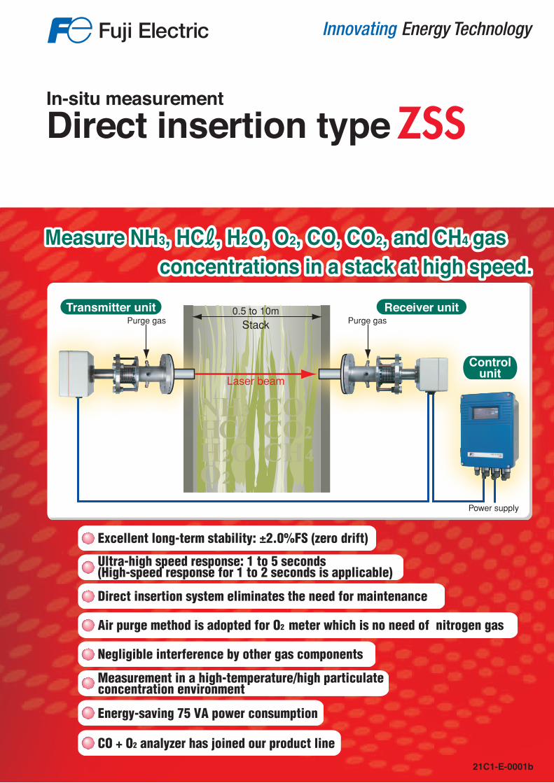
Direct insertion system eliminates the need for maintenance
Air purge method is adopted for O2 meter which is no need of nitrogen gas
Negligible interference by other gas components
Measurement in a high-temperature/high particulate concentration environment
Energy-saving 75 VA power consumption
CO + O2 analyzer has joined our product line
Ultra-high speed response: 1 to 5 seconds(High-speed response for 1 to 2 seconds is applicable)
Excellent long-term stability: ±2.0%FS (zero drift)
In-situ measurementDirect insertion type ZSS
COCO2CH4
NH3HCℓH2OO2
0.5 to 10mStack
Laser beam
Transmitter unit Receiver unit
Power supply
Purge gas Purge gas
Controlunit
Measure NH3, HCℓ, H2O, O2, CO, CO2, and CH4 gas concentrations in a stack at high speed.Measure NH3, HCℓ, H2O, O2, CO, CO2, and CH4 gas concentrations in a stack at high speed.
21C1-E-0001b
* Before using products in this catalog, be sure to read their instruction manuals in advance. Caution on Safety
Printed in Japan 2014-7/15FOLS
International Sales Div.Sales GroupGate City Ohsaki, East Tower, 11-2, Osaki 1-chome,Shinagawa-ku, Tokyo 141-0032, Japanhttp://www.fujielectric.comPhone: 81-3-5435-7280, 7281 Fax: 81-3-5435-7425http://www.fujielectric.com/products/instruments/
Information in this catalog is subject to change without notice.
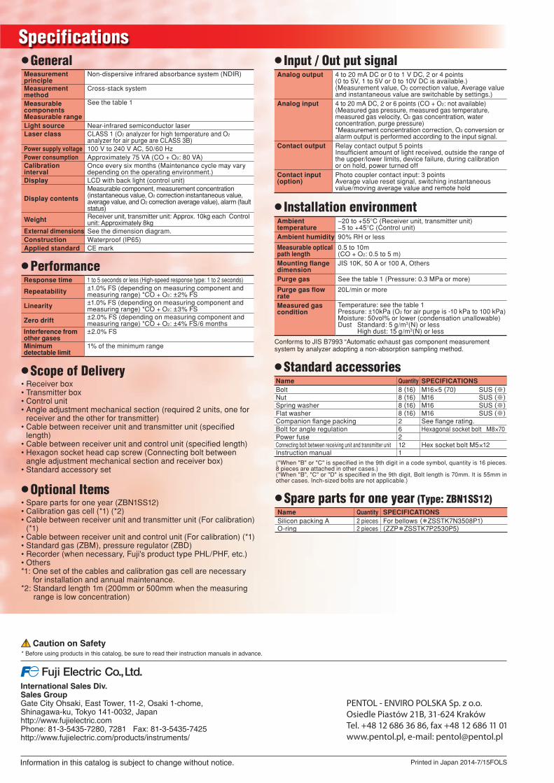
SpecificationsMeasurement principle
320
420
φ30
240
13074
DI/O
OA
IA
12134 3
φ10
.5 420
100100
150 to 200 150 to 200
0.5 to 10m(0.5 to 5m) Note 2
(160x240 (320) x 100) (Note 2)
120
160
φ551
16
(M16x55)
JIS10K50A FF
2
20 to 100L/min
Instrumentationair inlet
74
φ34φ34
φ14
Approx. 400 (432) (Note 2)
Mounting method
4-φ12 (mounting hole)
Power supply
2-φ12 (mounting hole)
Connecter
Cable between the controland receiver units(Standard: 5m, Max: 100m)
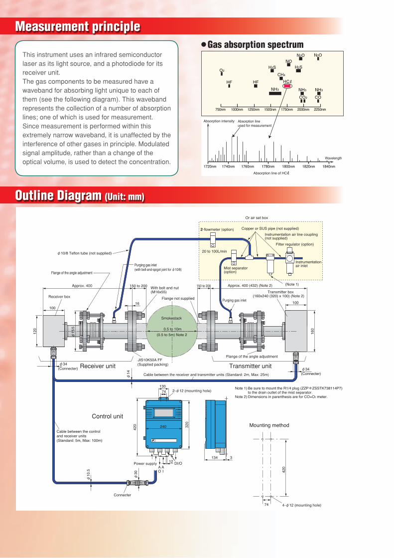
Note 1) Be sure to mount the R1/4 plug (ZZP*ZSSTK738114P7) to the drain outlet of the mist separator.Note 2) Dimensions in parenthesis are for CO+O2 meter.
(Connecter)(Connecter)
Flange of the angle adjustment
(Note 1)
Copper or SUS pipe (not supplied)
Or air set box
Instrumentation air line coupling (not supplied)
Filter regulator (option)
Mist separator(option)
φ10/8 Teflon tube (not supplied)
(with bell-and-spigot joint for φ10/8)
This instrument uses an infrared semiconductor laser as its light source, and a photodiode for its receiver unit. The gas components to be measured have a waveband for absorbing light unique to each of them (see the following diagram). This waveband represents the collection of a number of absorption lines; one of which is used for measurement. Since measurement is performed within this extremely narrow waveband, it is unaffected by the interference of other gases in principle. Modulated signal amplitude, rather than a change of the optical volume, is used to detect the concentration.
NH3 NH3NH3
HCℓ
CH4
CO2 CO
HF HF
H2S H2SNO
N2O N2O
O2
1720nm
750nm 1000nm 1250nm 1500nm 1750nm 2000nm 2250nm
1740nm 1760nm 1780nm 1800nm 1820nm 1840nm
Absorption lineused for measurement
Absorption intensity
Wavelength
Absorption line of HCℓ
●Gas absorption spectrum ●GeneralMeasurement principle
Non-dispersive infrared absorbance system (NDIR)
Measurement method
Cross-stack system
Measurable componentsMeasurable range
See the table 1
Light source Near-infrared semiconductor laserLaser class CLASS 1 (O2 analyzer for high temperature and O2
analyzer for air purge are CLASS 3B)Power supply voltage 100 V to 240 V AC, 50/60 HzPower consumption Approximately 75 VA (CO + O2: 80 VA)Calibration interval
Once every six months (Maintenance cycle may vary depending on the operating environment.)
Display LCD with back light (control unit)
Display contents
Measurable component, measurement concentration (instantaneous value, O2 correction instantaneous value, average value, and O2 correction average value), alarm (fault status)
Weight Receiver unit, transmitter unit: Approx. 10kg each Control unit: Approximately 8kg
External dimensions See the dimension diagram.Construction Waterproof (IP65)Applied standard CE mark
●Scope of Delivery• Receiver box• Transmitter box• Control unit• Angle adjustment mechanical section (required 2 units, one for
receiver and the other for transmitter) • Cable between receiver unit and transmitter unit (specifi ed
length)• Cable between receiver unit and control unit (specifi ed length)• Hexagon socket head cap screw (Connecting bolt between
angle adjustment mechanical section and receiver box)• Standard accessory set
●Optional Items• Spare parts for one year (ZBN1SS12)• Calibration gas cell (*1) (*2)• Cable between receiver unit and transmitter unit (For calibration)
(*1)• Cable between receiver unit and control unit (For calibration) (*1)• Standard gas (ZBM), pressure regulator (ZBD)• Recorder (when necessary, Fuji's product type PHL/PHF, etc.)• Others*1: One set of the cables and calibration gas cell are necessary
for installation and annual maintenance.*2: Standard length 1m (200mm or 500mm when the measuring
range is low concentration)
●PerformanceResponse time 1 to 5 seconds or less (High-speed response type: 1 to 2 seconds)
Repeatability ±1.0% FS (depending on measuring component and measuring range) *CO + O2: ±2% FS
Linearity ±1.0% FS (depending on measuring component and measuring range) *CO + O2: ±3% FS
Zero drift ±2.0% FS (depending on measuring component and measuring range) *CO + O2: ±4% FS/6 months
Interference from other gases
±2.0% FS
Minimum detectable limit
1% of the minimum range
● Input / Out put signalAnalog output 4 to 20 mA DC or 0 to 1 V DC, 2 or 4 points
(0 to 5V, 1 to 5V or 0 to 10V DC is available.)(Measurement value, O2 correction value, Average value and instantaneous value are switchable by settings.)
Analog input 4 to 20 mA DC, 2 or 6 points (CO + O2: not available) (Measured gas pressure, measured gas temperature, measured gas velocity, O2 gas concentration, water concentration, purge pressure)*Measurement concentration correction, O2 conversion or alarm output is performed according to the input signal.
Contact output Relay contact output 5 pointsInsuffi cient amount of light received, outside the range of the upper/lower limits, device failure, during calibration or on hold, power turned off
Contact input (option)
Photo coupler contact input: 3 pointsAverage value reset signal, switching instantaneous value/moving average value and remote hold
●Standard accessoriesName Quantity SPECIFICATIONSBolt 8 (16) M16×5 (70) SUS (※)Nut 8 (16) M16 SUS (※)Spring washer 8 (16) M16 SUS (※)Flat washer 8 (16) M16 SUS (※)Companion fl ange packing 2 See fl ange rating.Bolt for angle regulation 6 Hexagonal socket bolt M8×70Power fuse 2Connecting bolt between receiving unit and transmitter unit 12 Hex socket bolt M5×12Instruction manual 1
(*When "B" or "C" is specifi ed in the 9th digit in a code symbol, quantity is 16 pieces. 8 pieces are attached in other cases.)(*When "B", "C" or "D" is specifi ed in the 9th digit, Bolt length is 70mm. It is 55mm in other cases. Inch-sized bolts are not applicable.)
●Spare parts for one year (Type: ZBN1SS12)Name Quantity SPECIFICATIONSSilicon packing A 2 pieces For bellows (*ZSSTK7N3508P1)O-ring 2 pieces (ZZP*ZSSTK7P2530P5)
● Installation environmentAmbient temperature
−20 to +55°C (Receiver unit, transmitter unit)−5 to +45°C (Control unit)
Ambient humidity 90% RH or less
Measurable optical path length
0.5 to 10m(CO + O2: 0.5 to 5 m)
Mounting fl ange dimension
JIS 10K, 50 A or 100 A, Others
Purge gas See the table 1 (Pressure: 0.3 MPa or more)
Purge gas fl ow rate
20L/min or more
Measured gas condition
Temperature: see the table 1Pressure: ±10kPa (O2 for air purge is -10 kPa to 100 kPa)Moisture: 50vol% or lower (condensation unallowable)Dust Standard: 5 g/m3(N) or less
High dust: 15 g/m3(N) or less
Conforms to JIS B7993 “Automatic exhaust gas component measurement system by analyzer adopting a non-absorption sampling method.
Outline Diagram (Unit: mm)
Measures various gas components. 2-component analyzer available!
DustStandard: 5 g/m3 (N) or lessHigh dust: 15 g/m3 (N) or less
■ An ultra-high speed measurement (within 2 seconds): 8minutes faster than gas sampling method
■ Energy efficient, low running cost Low-power consumption (75VA maximum). Low maintenance (at most 2 times/year) reduces running cost.
■ Easy maintenance No need of gas sampling, pretreatment, or parts replacement such as filters and catalysts.
■ Barely affected by the interference of other gas components
Minimal interference from other gasses thanks to the use of an infrared semiconductor laser, which matches the absorption wavelength of the measuring components.
■ Excellent long-term stability±2.0%FS (zero drift)17:00 16:00 18:00 19:00
40
20
0
60
80
100
120
140 Approximately
8 minuteApproximately
8 minuteApproximately
8 minuteApproximately
8 minute
HCℓ(ppm)
Time
Cross stack laser gas analyzer Ion electrode system (Sampling conduit: Approximately 20m)
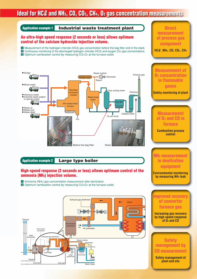
Direct measurement of process gas
componentHCℓ, NH3, CO, CO2, CH4
Measurement of O2 concentration
in flammable gases
Safety monitoring of plant
Measurement of O2 and CO in
furnaceCombustion process
control
NH3 measurement in denitration
equipmentEnvironmental monitoring
by measuring NH3 leak
Improved recovery of converter furnace gas
Increasing gas recovery by high-speed response
of O2 and CO
Safety management by CO measurementSafety management of
plant and silo
An ultra-high speed response (2 seconds or less) allows optimum control of the calcium hydroxide injection volume.
High-speed response (2 seconds or less) allows optimum control of the ammonia (NH3) injection volume.
●Sludge
●Mixed waste
●Infectious waste●Industrial waste subject to special control
●Waste oil●Waste acid●Waste alkali
Secondarycombustion
chamber
Kiln stoker-firedfurnace
AshFly ash (dust)
Sludge dryer
Waste-heatboiler
Bag filter
SteamGenerator
Exhaust gasSteam turbine
G
Gas cooling tower
Catalyst tower
Chimney
Before the bag fi lter Stack
Air Air preheater
Exhaust gas denitrizerBoiler
Electrostaticprecipitator
Coal ash
Chimney
Exhaustgas
denitrizer
Exhaustgas
denitrizer Air Airpreheater
Exhaust gas denitrizer
Plaster
Coal ash
Boiler Steam turbineGenerator
Dehydrator
Outlet
Water intake
TransformerTransformer
Coalpulverizer
Heatexchanger
Electrostaticprecipitator
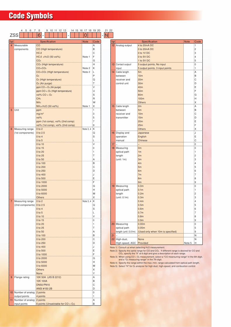
Code Symbols
Note 1) Consult us when selecting H2O measurement.
Note 2) Specify the same range for CO and CO2. If different range is desired for CO and CO2, specify the “X” at 6 digit and give a description of each range.
Note 3) When using CO + O2 measurement, select a "CO mearsuring range" in the 6th digit, and a "O2 measuring range" in the 7th digit.
Note 4) Specify the range within the max./min. range calculated from optical path length.
Note 5) Select "H" for O2 analyzer for high dust, high-speed, and combustion control.
4 5 6 7 8 9 10 11 12 13 14 15 16 17 18 19 20 21 22
ZSS 6 - - 0 - NDigit Specifi cation Note Code4 Measurable CO A
components CO (High temperature) B
HCℓ C
HCℓ+H2O (50 vol%) Note 1 F
CO2 G
CO2 (High temperature) H
CO+CO2 Note 2 K
CO+CO2 (High temperature) Note 2 L
O2 P
O2 (High temperature) Q
O2 (Air purge) T
ppm CO + O2 (Air purge) V
ppm CO + O2 (High temperature) U
vol% CO + O2 S
CH4 R
NH3 W
NH3+H2O (50 vol%) Note 1 X
5 Unit ppm 1
mg/m3 3
vol% 5
ppm (1st comp), vol% (2nd comp) 7
vol% (1st comp), vol% (2nd comp) 9
6 Measuring range 0 to 2 Note 3, 4 K
(1st components) 0 to 2.5 Q
0 to 4 S
0 to 5 L
0 to 10 V
0 to 15 0
0 to 20 1
0 to 25 T
0 to 50 A
0 to 100 B
0 to 200 C
0 to 250 D
0 to 400 J
0 to 500 E
0 to 1000 F
0 to 2000 G
0 to 5000 H
0 to 6000 M
Others X
7 Measuring range 0 to 2 Note 3, 4 K
(2nd components) 0 to 2.5 Q
0 to 4 S
0 to 5 L
0 to 10 V
0 to 15 0
0 to 20 1
0 to 25 T
0 to 50 A
0 to 100 B
0 to 200 C
0 to 250 D
0 to 400 J
0 to 500 E
0 to 1000 F
0 to 2000 G
0 to 5000 H
0 to 6000 M
Others X
None Y
9 Flange rating 10K 50A (JIS B 2212) A
10K 100A B
DN50/PN10 C
ANSI #150 2B D
10 Number of analog 2 points 0
output points 4 points 1
11 Number of analog 2 points A
input points 6 points (Unselctable for CO + O2) B
Digit Specifi cation Note Code12 Analog output 4 to 20mA DC 1
0 to 20mA DC 2
0 to 1V DC 3
0 to 5V DC 4
1 to 5V DC 5
13 Contact output/ 5 output points, No input 0
input 5 output points, 3 input points 1
14 Cable length 5m A
between 10m B
receiver and 20m C
control unit 30m D
40m E
50m F
80m G
100m H
Others X
15 Cable length 2m A
between 5m B
receiver and 10m C
transmitter 15m D
20m E
25m F
Others X
16 Display and Japanese J
operation English E
manual Chinese C
17 − − 0
18 Measuring 0m 0
optical path 1m 1
length 2m 2
(unit: 1m) 3m 3
4m 4
5m 5
6m 6
7m 7
8m 8
9m 9
19 Measuring 0.0m 0
optical path 0.1m 1
length 0.2m 2
(unit: 0.1m) 0.3m 3
0.4m 4
0.5m 5
0.6m 6
0.7m 7
0.8m 8
0.9m 9
20 Measuring 0.00m 0
optical path 0.05m 5
length (unit: 0.01m) (Used only when 10m is specifi ed) 9
21 − − N
22 High-dust, None N
High-speed, AGC Provided Note 5 H
Ideal for HCℓ and NH3, CO, CO2, CH4, O2 gas concentration measurements
Application example 2 Large type boiler
Application example 1 Industrial waste treatment plant
1 Measurement of the hydrogen chloride (HCℓ) gas concentration before the bag filter and in the stack.2 Continuous monitoring of the discharged hydrogen chloride (HCℓ) and oxygen (O2) gas concentrations.3 Optimum combustion control by measuring CO+O2 at the furnace outlet.
1 Ammonia (NH3) gas concentration measurement after denitration.2 Optimum combustion control by measuring CO+O2 at the furnace outlet.
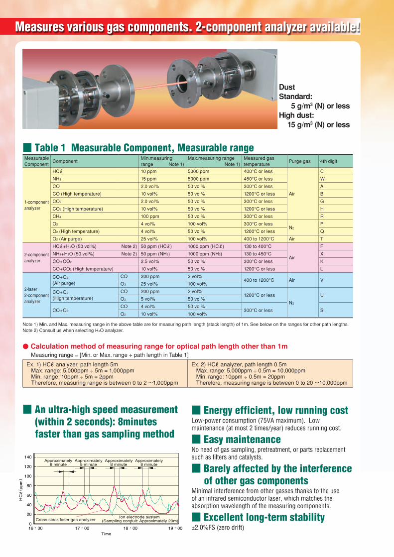
■ Table 1 Measurable Component, Measurable rangeMeasurable Component
ComponentMin.measuring range Note 1)
Max.measuring range Note 1)
Measured gas temperature
Purge gas 4th digit
1-component analyzer
HCℓ 10 ppm 5000 ppm 400°C or less
Air
C
NH3 15 ppm 5000 ppm 450°C or less W
CO 2.0 vol% 50 vol% 300°C or less A
CO (High temperature) 10 vol% 50 vol% 1200°C or less B
CO2 2.0 vol% 50 vol% 300°C or less G
CO2 (High temperature) 10 vol% 50 vol% 1200°C or less H
CH4 100 ppm 50 vol% 300°C or less R
O2 4 vol% 100 vol% 300°C or lessN2
P
O2 (High temperature) 4 vol% 50 vol% 1200°C or less Q
O2 (Air purge) 25 vol% 100 vol% 400 to 1200°C Air T
2-component analyzer
HCℓ+H2O (50 vol%) Note 2) 50 ppm (HCℓ) 1000 ppm (HCℓ) 130 to 400°C
Air
F
NH3+H2O (50 vol%) Note 2) 50 ppm (NH3) 1000 ppm (NH3) 130 to 450°C X
CO+CO2 2.5 vol% 50 vol% 300°C or less K
CO+CO2 (High temperature) 10 vol% 50 vol% 1200°C or less L
2-laser 2-component analyzer
CO+O2
(Air purge)CO 200 ppm 2 vol%
400 to 1200°C Air VO2 25 vol% 100 vol%
CO+O2
(High temperature)CO 200 ppm 2 vol%
1200°C or less
N2
UO2 5 vol% 50 vol%
CO+O2CO 4 vol% 50 vol%
300°C or less SO2 10 vol% 100 vol%
Note 1) Min. and Max. measuring range in the above table are for measuring path length (stack length) of 1m. See below on the ranges for other path lengths.Note 2) Consult us when selecting H2O analyzer.
● Calculation method of measuring range for optical path length other than 1mMeasuring range = [Min. or Max. range ÷ path length in Table 1]
Ex. 1) HCℓ analyzer, path length 5m Max. range: 5,000ppm ÷ 5m = 1,000ppm Min. range: 10ppm ÷ 5m = 2ppm Therefore, measuring range is between 0 to 2 ···1,000ppm
Ex. 2) HCℓ analyzer, path length 0.5m Max. range: 5,000ppm ÷ 0.5m = 10,000ppm Min. range: 10ppm ÷ 0.5m = 20ppm Therefore, measuring range is between 0 to 20 ···10,000ppm
Measures various gas components. 2-component analyzer available!
DustStandard: 5 g/m3 (N) or lessHigh dust: 15 g/m3 (N) or less
■ An ultra-high speed measurement (within 2 seconds): 8minutes faster than gas sampling method
■ Energy efficient, low running cost Low-power consumption (75VA maximum). Low maintenance (at most 2 times/year) reduces running cost.
■ Easy maintenance No need of gas sampling, pretreatment, or parts replacement such as filters and catalysts.
■ Barely affected by the interference of other gas components
Minimal interference from other gasses thanks to the use of an infrared semiconductor laser, which matches the absorption wavelength of the measuring components.
■ Excellent long-term stability±2.0%FS (zero drift)17:00 16:00 18:00 19:00
40
20
0
60
80
100
120
140 Approximately
8 minuteApproximately
8 minuteApproximately
8 minuteApproximately
8 minute
HCℓ(ppm)
Time
Cross stack laser gas analyzer Ion electrode system (Sampling conduit: Approximately 20m)
Direct measurement of process gas
componentHCℓ, NH3, CO, CO2, CH4
Measurement of O2 concentration
in flammable gases
Safety monitoring of plant
Measurement of O2 and CO in
furnaceCombustion process
control
NH3 measurement in denitration
equipmentEnvironmental monitoring
by measuring NH3 leak
Improved recovery of converter furnace gas
Increasing gas recovery by high-speed response
of O2 and CO
Safety management by CO measurementSafety management of
plant and silo
An ultra-high speed response (2 seconds or less) allows optimum control of the calcium hydroxide injection volume.
High-speed response (2 seconds or less) allows optimum control of the ammonia (NH3) injection volume.
●Sludge
●Mixed waste
●Infectious waste●Industrial waste subject to special control
●Waste oil●Waste acid●Waste alkali
Secondarycombustion
chamber
Kiln stoker-firedfurnace
AshFly ash (dust)
Sludge dryer
Waste-heatboiler
Bag filter
SteamGenerator
Exhaust gasSteam turbine
G
Gas cooling tower
Catalyst tower
Chimney
Before the bag fi lter Stack
Air Air preheater
Exhaust gas denitrizerBoiler
Electrostaticprecipitator
Coal ash
Chimney
Exhaustgas
denitrizer
Exhaustgas
denitrizer Air Airpreheater
Exhaust gas denitrizer
Plaster
Coal ash
Boiler Steam turbineGenerator
Dehydrator
Outlet
Water intake
TransformerTransformer
Coalpulverizer
Heatexchanger
Electrostaticprecipitator
Code Symbols
Note 1) Consult us when selecting H2O measurement.
Note 2) Specify the same range for CO and CO2. If different range is desired for CO and CO2, specify the “X” at 6 digit and give a description of each range.
Note 3) When using CO + O2 measurement, select a "CO mearsuring range" in the 6th digit, and a "O2 measuring range" in the 7th digit.
Note 4) Specify the range within the max./min. range calculated from optical path length.
Note 5) Select "H" for O2 analyzer for high dust, high-speed, and combustion control.
4 5 6 7 8 9 10 11 12 13 14 15 16 17 18 19 20 21 22
ZSS 6 - - 0 - NDigit Specifi cation Note Code4 Measurable CO A
components CO (High temperature) B
HCℓ C
HCℓ+H2O (50 vol%) Note 1 F
CO2 G
CO2 (High temperature) H
CO+CO2 Note 2 K
CO+CO2 (High temperature) Note 2 L
O2 P
O2 (High temperature) Q
O2 (Air purge) T
ppm CO + O2 (Air purge) V
ppm CO + O2 (High temperature) U
vol% CO + O2 S
CH4 R
NH3 W
NH3+H2O (50 vol%) Note 1 X
5 Unit ppm 1
mg/m3 3
vol% 5
ppm (1st comp), vol% (2nd comp) 7
vol% (1st comp), vol% (2nd comp) 9
6 Measuring range 0 to 2 Note 3, 4 K
(1st components) 0 to 2.5 Q
0 to 4 S
0 to 5 L
0 to 10 V
0 to 15 0
0 to 20 1
0 to 25 T
0 to 50 A
0 to 100 B
0 to 200 C
0 to 250 D
0 to 400 J
0 to 500 E
0 to 1000 F
0 to 2000 G
0 to 5000 H
0 to 6000 M
Others X
7 Measuring range 0 to 2 Note 3, 4 K
(2nd components) 0 to 2.5 Q
0 to 4 S
0 to 5 L
0 to 10 V
0 to 15 0
0 to 20 1
0 to 25 T
0 to 50 A
0 to 100 B
0 to 200 C
0 to 250 D
0 to 400 J
0 to 500 E
0 to 1000 F
0 to 2000 G
0 to 5000 H
0 to 6000 M
Others X
None Y
9 Flange rating 10K 50A (JIS B 2212) A
10K 100A B
DN50/PN10 C
ANSI #150 2B D
10 Number of analog 2 points 0
output points 4 points 1
11 Number of analog 2 points A
input points 6 points (Unselctable for CO + O2) B
Digit Specifi cation Note Code12 Analog output 4 to 20mA DC 1
0 to 20mA DC 2
0 to 1V DC 3
0 to 5V DC 4
1 to 5V DC 5
13 Contact output/ 5 output points, No input 0
input 5 output points, 3 input points 1
14 Cable length 5m A
between 10m B
receiver and 20m C
control unit 30m D
40m E
50m F
80m G
100m H
Others X
15 Cable length 2m A
between 5m B
receiver and 10m C
transmitter 15m D
20m E
25m F
Others X
16 Display and Japanese J
operation English E
manual Chinese C
17 − − 0
18 Measuring 0m 0
optical path 1m 1
length 2m 2
(unit: 1m) 3m 3
4m 4
5m 5
6m 6
7m 7
8m 8
9m 9
19 Measuring 0.0m 0
optical path 0.1m 1
length 0.2m 2
(unit: 0.1m) 0.3m 3
0.4m 4
0.5m 5
0.6m 6
0.7m 7
0.8m 8
0.9m 9
20 Measuring 0.00m 0
optical path 0.05m 5
length (unit: 0.01m) (Used only when 10m is specifi ed) 9
21 − − N
22 High-dust, None N
High-speed, AGC Provided Note 5 H
Ideal for HCℓ and NH3, CO, CO2, CH4, O2 gas concentration measurements
Application example 2 Large type boiler
Application example 1 Industrial waste treatment plant
1 Measurement of the hydrogen chloride (HCℓ) gas concentration before the bag filter and in the stack.2 Continuous monitoring of the discharged hydrogen chloride (HCℓ) and oxygen (O2) gas concentrations.3 Optimum combustion control by measuring CO+O2 at the furnace outlet.
1 Ammonia (NH3) gas concentration measurement after denitration.2 Optimum combustion control by measuring CO+O2 at the furnace outlet.
■ Table 1 Measurable Component, Measurable rangeMeasurable Component
ComponentMin.measuring range Note 1)
Max.measuring range Note 1)
Measured gas temperature
Purge gas 4th digit
1-component analyzer
HCℓ 10 ppm 5000 ppm 400°C or less
Air
C
NH3 15 ppm 5000 ppm 450°C or less W
CO 2.0 vol% 50 vol% 300°C or less A
CO (High temperature) 10 vol% 50 vol% 1200°C or less B
CO2 2.0 vol% 50 vol% 300°C or less G
CO2 (High temperature) 10 vol% 50 vol% 1200°C or less H
CH4 100 ppm 50 vol% 300°C or less R
O2 4 vol% 100 vol% 300°C or lessN2
P
O2 (High temperature) 4 vol% 50 vol% 1200°C or less Q
O2 (Air purge) 25 vol% 100 vol% 400 to 1200°C Air T
2-component analyzer
HCℓ+H2O (50 vol%) Note 2) 50 ppm (HCℓ) 1000 ppm (HCℓ) 130 to 400°C
Air
F
NH3+H2O (50 vol%) Note 2) 50 ppm (NH3) 1000 ppm (NH3) 130 to 450°C X
CO+CO2 2.5 vol% 50 vol% 300°C or less K
CO+CO2 (High temperature) 10 vol% 50 vol% 1200°C or less L
2-laser 2-component analyzer
CO+O2
(Air purge)CO 200 ppm 2 vol%
400 to 1200°C Air VO2 25 vol% 100 vol%
CO+O2
(High temperature)CO 200 ppm 2 vol%
1200°C or less
N2
UO2 5 vol% 50 vol%
CO+O2CO 4 vol% 50 vol%
300°C or less SO2 10 vol% 100 vol%
Note 1) Min. and Max. measuring range in the above table are for measuring path length (stack length) of 1m. See below on the ranges for other path lengths.Note 2) Consult us when selecting H2O analyzer.
● Calculation method of measuring range for optical path length other than 1mMeasuring range = [Min. or Max. range ÷ path length in Table 1]
Ex. 1) HCℓ analyzer, path length 5m Max. range: 5,000ppm ÷ 5m = 1,000ppm Min. range: 10ppm ÷ 5m = 2ppm Therefore, measuring range is between 0 to 2 ···1,000ppm
Ex. 2) HCℓ analyzer, path length 0.5m Max. range: 5,000ppm ÷ 0.5m = 10,000ppm Min. range: 10ppm ÷ 0.5m = 20ppm Therefore, measuring range is between 0 to 20 ···10,000ppm
Direct insertion system eliminates the need for maintenance
Air purge method is adopted for O2 meter which is no need of nitrogen gas
Negligible interference by other gas components
Measurement in a high-temperature/high particulate concentration environment
Energy-saving 75 VA power consumption
CO + O2 analyzer has joined our product line
Ultra-high speed response: 1 to 5 seconds(High-speed response for 1 to 2 seconds is applicable)
Excellent long-term stability: ±2.0%FS (zero drift)
In-situ measurementDirect insertion type ZSS
COCO2CH4
NH3HCℓH2OO2
0.5 to 10mStack
Laser beam
Transmitter unit Receiver unit
Power supply
Purge gas Purge gas
Controlunit
Measure NH3, HCℓ, H2O, O2, CO, CO2, and CH4 gas concentrations in a stack at high speed.Measure NH3, HCℓ, H2O, O2, CO, CO2, and CH4 gas concentrations in a stack at high speed.
21C1-E-0001b
* Before using products in this catalog, be sure to read their instruction manuals in advance. Caution on Safety
Printed in Japan 2014-7/15FOLS
International Sales Div.Sales GroupGate City Ohsaki, East Tower, 11-2, Osaki 1-chome,Shinagawa-ku, Tokyo 141-0032, Japanhttp://www.fujielectric.comPhone: 81-3-5435-7280, 7281 Fax: 81-3-5435-7425http://www.fujielectric.com/products/instruments/
Information in this catalog is subject to change without notice.
SpecificationsMeasurement principle
320
420
φ30
240
13074
DI/O
OA
IA
12134 3
φ10
.5 420
100100
150 to 200 150 to 200
0.5 to 10m(0.5 to 5m) Note 2
(160x240 (320) x 100) (Note 2)
120
160
φ551
16
(M16x55)
JIS10K50A FF
2
20 to 100L/min
Instrumentationair inlet
74
φ34φ34
φ14
Approx. 400 (432) (Note 2)
Mounting method
4-φ12 (mounting hole)
Power supply
2-φ12 (mounting hole)
Connecter
Cable between the controland receiver units(Standard: 5m, Max: 100m)
Note 1) Be sure to mount the R1/4 plug (ZZP*ZSSTK738114P7) to the drain outlet of the mist separator.Note 2) Dimensions in parenthesis are for CO+O2 meter.
(Connecter)(Connecter)
Flange of the angle adjustment
(Note 1)
Copper or SUS pipe (not supplied)
Or air set box
Instrumentation air line coupling (not supplied)
Filter regulator (option)
Mist separator(option)
φ10/8 Teflon tube (not supplied)
(with bell-and-spigot joint for φ10/8)
This instrument uses an infrared semiconductor laser as its light source, and a photodiode for its receiver unit. The gas components to be measured have a waveband for absorbing light unique to each of them (see the following diagram). This waveband represents the collection of a number of absorption lines; one of which is used for measurement. Since measurement is performed within this extremely narrow waveband, it is unaffected by the interference of other gases in principle. Modulated signal amplitude, rather than a change of the optical volume, is used to detect the concentration.
NH3 NH3NH3
HCℓ
CH4
CO2 CO
HF HF
H2S H2SNO
N2O N2O
O2
1720nm
750nm 1000nm 1250nm 1500nm 1750nm 2000nm 2250nm
1740nm 1760nm 1780nm 1800nm 1820nm 1840nm
Absorption lineused for measurement
Absorption intensity
Wavelength
Absorption line of HCℓ
●Gas absorption spectrum ●GeneralMeasurement principle
Non-dispersive infrared absorbance system (NDIR)
Measurement method
Cross-stack system
Measurable componentsMeasurable range
See the table 1
Light source Near-infrared semiconductor laserLaser class CLASS 1 (O2 analyzer for high temperature and O2
analyzer for air purge are CLASS 3B)Power supply voltage 100 V to 240 V AC, 50/60 HzPower consumption Approximately 75 VA (CO + O2: 80 VA)Calibration interval
Once every six months (Maintenance cycle may vary depending on the operating environment.)
Display LCD with back light (control unit)
Display contents
Measurable component, measurement concentration (instantaneous value, O2 correction instantaneous value, average value, and O2 correction average value), alarm (fault status)
Weight Receiver unit, transmitter unit: Approx. 10kg each Control unit: Approximately 8kg
External dimensions See the dimension diagram.Construction Waterproof (IP65)Applied standard CE mark
●Scope of Delivery• Receiver box• Transmitter box• Control unit• Angle adjustment mechanical section (required 2 units, one for
receiver and the other for transmitter) • Cable between receiver unit and transmitter unit (specifi ed
length)• Cable between receiver unit and control unit (specifi ed length)• Hexagon socket head cap screw (Connecting bolt between
angle adjustment mechanical section and receiver box)• Standard accessory set
●Optional Items• Spare parts for one year (ZBN1SS12)• Calibration gas cell (*1) (*2)• Cable between receiver unit and transmitter unit (For calibration)
(*1)• Cable between receiver unit and control unit (For calibration) (*1)• Standard gas (ZBM), pressure regulator (ZBD)• Recorder (when necessary, Fuji's product type PHL/PHF, etc.)• Others*1: One set of the cables and calibration gas cell are necessary
for installation and annual maintenance.*2: Standard length 1m (200mm or 500mm when the measuring
range is low concentration)
●PerformanceResponse time 1 to 5 seconds or less (High-speed response type: 1 to 2 seconds)
Repeatability ±1.0% FS (depending on measuring component and measuring range) *CO + O2: ±2% FS
Linearity ±1.0% FS (depending on measuring component and measuring range) *CO + O2: ±3% FS
Zero drift ±2.0% FS (depending on measuring component and measuring range) *CO + O2: ±4% FS/6 months
Interference from other gases
±2.0% FS
Minimum detectable limit
1% of the minimum range
● Input / Out put signalAnalog output 4 to 20 mA DC or 0 to 1 V DC, 2 or 4 points
(0 to 5V, 1 to 5V or 0 to 10V DC is available.)(Measurement value, O2 correction value, Average value and instantaneous value are switchable by settings.)
Analog input 4 to 20 mA DC, 2 or 6 points (CO + O2: not available) (Measured gas pressure, measured gas temperature, measured gas velocity, O2 gas concentration, water concentration, purge pressure)*Measurement concentration correction, O2 conversion or alarm output is performed according to the input signal.
Contact output Relay contact output 5 pointsInsuffi cient amount of light received, outside the range of the upper/lower limits, device failure, during calibration or on hold, power turned off
Contact input (option)
Photo coupler contact input: 3 pointsAverage value reset signal, switching instantaneous value/moving average value and remote hold
●Standard accessoriesName Quantity SPECIFICATIONSBolt 8 (16) M16×5 (70) SUS (※)Nut 8 (16) M16 SUS (※)Spring washer 8 (16) M16 SUS (※)Flat washer 8 (16) M16 SUS (※)Companion fl ange packing 2 See fl ange rating.Bolt for angle regulation 6 Hexagonal socket bolt M8×70Power fuse 2Connecting bolt between receiving unit and transmitter unit 12 Hex socket bolt M5×12Instruction manual 1
(*When "B" or "C" is specifi ed in the 9th digit in a code symbol, quantity is 16 pieces. 8 pieces are attached in other cases.)(*When "B", "C" or "D" is specifi ed in the 9th digit, Bolt length is 70mm. It is 55mm in other cases. Inch-sized bolts are not applicable.)
●Spare parts for one year (Type: ZBN1SS12)Name Quantity SPECIFICATIONSSilicon packing A 2 pieces For bellows (*ZSSTK7N3508P1)O-ring 2 pieces (ZZP*ZSSTK7P2530P5)
● Installation environmentAmbient temperature
−20 to +55°C (Receiver unit, transmitter unit)−5 to +45°C (Control unit)
Ambient humidity 90% RH or less
Measurable optical path length
0.5 to 10m(CO + O2: 0.5 to 5 m)
Mounting fl ange dimension
JIS 10K, 50 A or 100 A, Others
Purge gas See the table 1 (Pressure: 0.3 MPa or more)
Purge gas fl ow rate
20L/min or more
Measured gas condition
Temperature: see the table 1Pressure: ±10kPa (O2 for air purge is -10 kPa to 100 kPa)Moisture: 50vol% or lower (condensation unallowable)Dust Standard: 5 g/m3(N) or less
High dust: 15 g/m3(N) or less
Conforms to JIS B7993 “Automatic exhaust gas component measurement system by analyzer adopting a non-absorption sampling method.
Outline Diagram (Unit: mm)
Direct insertion system eliminates the need for maintenance
Air purge method is adopted for O2 meter which is no need of nitrogen gas
Negligible interference by other gas components
Measurement in a high-temperature/high particulate concentration environment
Energy-saving 75 VA power consumption
CO + O2 analyzer has joined our product line
Ultra-high speed response: 1 to 5 seconds(High-speed response for 1 to 2 seconds is applicable)
Excellent long-term stability: ±2.0%FS (zero drift)
In-situ measurementDirect insertion type ZSS
COCO2CH4
NH3HCℓH2OO2
0.5 to 10mStack
Laser beam
Transmitter unit Receiver unit
Power supply
Purge gas Purge gas
Controlunit
Measure NH3, HCℓ, H2O, O2, CO, CO2, and CH4 gas concentrations in a stack at high speed.Measure NH3, HCℓ, H2O, O2, CO, CO2, and CH4 gas concentrations in a stack at high speed.
21C1-E-0001b
* Before using products in this catalog, be sure to read their instruction manuals in advance.
Caution on Safety
Printed in Japan 2014-7/15FOLS
International Sales Div.Sales GroupGate City Ohsaki, East Tower, 11-2, Osaki 1-chome,Shinagawa-ku, Tokyo 141-0032, Japanhttp://www.fujielectric.comPhone: 81-3-5435-7280, 7281 Fax: 81-3-5435-7425http://www.fujielectric.com/products/instruments/
Information in this catalog is subject to change without notice.
PENTOL - ENVIRO POLSKA Sp. z o.o.Osiedle Piastów 21B, 31-624 KrakówTel. +48 12 686 36 86, fax +48 12 686 11 01www.pentol.pl, e-mail: [email protected]
SpecificationsMeasurement principle
320
420
φ30
240
13074
DI/O
OA
IA
12134 3
φ10
.5 420
100100
150 to 200 150 to 200
0.5 to 10m(0.5 to 5m) Note 2
(160x240 (320) x 100) (Note 2)
120
160
φ551
16
(M16x55)
JIS10K50A FF
2
20 to 100L/min
Instrumentationair inlet
74
φ34φ34
φ14
Approx. 400 (432) (Note 2)
Mounting method
4-φ12 (mounting hole)
Power supply
2-φ12 (mounting hole)
Connecter
Cable between the controland receiver units(Standard: 5m, Max: 100m)
Note 1) Be sure to mount the R1/4 plug (ZZP*ZSSTK738114P7) to the drain outlet of the mist separator.Note 2) Dimensions in parenthesis are for CO+O2 meter.
(Connecter)(Connecter)
Flange of the angle adjustment
(Note 1)
Copper or SUS pipe (not supplied)
Or air set box
Instrumentation air line coupling (not supplied)
Filter regulator (option)
Mist separator(option)
φ10/8 Teflon tube (not supplied)
(with bell-and-spigot joint for φ10/8)
This instrument uses an infrared semiconductor laser as its light source, and a photodiode for its receiver unit. The gas components to be measured have a waveband for absorbing light unique to each of them (see the following diagram). This waveband represents the collection of a number of absorption lines; one of which is used for measurement. Since measurement is performed within this extremely narrow waveband, it is unaffected by the interference of other gases in principle. Modulated signal amplitude, rather than a change of the optical volume, is used to detect the concentration.
NH3 NH3NH3
HCℓ
CH4
CO2 CO
HF HF
H2S H2SNO
N2O N2O
O2
1720nm
750nm 1000nm 1250nm 1500nm 1750nm 2000nm 2250nm
1740nm 1760nm 1780nm 1800nm 1820nm 1840nm
Absorption lineused for measurement
Absorption intensity
Wavelength
Absorption line of HCℓ
●Gas absorption spectrum ●GeneralMeasurement principle
Non-dispersive infrared absorbance system (NDIR)
Measurement method
Cross-stack system
Measurable componentsMeasurable range
See the table 1
Light source Near-infrared semiconductor laserLaser class CLASS 1 (O2 analyzer for high temperature and O2
analyzer for air purge are CLASS 3B)Power supply voltage 100 V to 240 V AC, 50/60 HzPower consumption Approximately 75 VA (CO + O2: 80 VA)Calibration interval
Once every six months (Maintenance cycle may vary depending on the operating environment.)
Display LCD with back light (control unit)
Display contents
Measurable component, measurement concentration (instantaneous value, O2 correction instantaneous value, average value, and O2 correction average value), alarm (fault status)
Weight Receiver unit, transmitter unit: Approx. 10kg each Control unit: Approximately 8kg
External dimensions See the dimension diagram.Construction Waterproof (IP65)Applied standard CE mark
●Scope of Delivery• Receiver box• Transmitter box• Control unit• Angle adjustment mechanical section (required 2 units, one for
receiver and the other for transmitter) • Cable between receiver unit and transmitter unit (specifi ed
length)• Cable between receiver unit and control unit (specifi ed length)• Hexagon socket head cap screw (Connecting bolt between
angle adjustment mechanical section and receiver box)• Standard accessory set
●Optional Items• Spare parts for one year (ZBN1SS12)• Calibration gas cell (*1) (*2)• Cable between receiver unit and transmitter unit (For calibration)
(*1)• Cable between receiver unit and control unit (For calibration) (*1)• Standard gas (ZBM), pressure regulator (ZBD)• Recorder (when necessary, Fuji's product type PHL/PHF, etc.)• Others*1: One set of the cables and calibration gas cell are necessary
for installation and annual maintenance.*2: Standard length 1m (200mm or 500mm when the measuring
range is low concentration)
●PerformanceResponse time 1 to 5 seconds or less (High-speed response type: 1 to 2 seconds)
Repeatability ±1.0% FS (depending on measuring component and measuring range) *CO + O2: ±2% FS
Linearity ±1.0% FS (depending on measuring component and measuring range) *CO + O2: ±3% FS
Zero drift ±2.0% FS (depending on measuring component and measuring range) *CO + O2: ±4% FS/6 months
Interference from other gases
±2.0% FS
Minimum detectable limit
1% of the minimum range
● Input / Out put signalAnalog output 4 to 20 mA DC or 0 to 1 V DC, 2 or 4 points
(0 to 5V, 1 to 5V or 0 to 10V DC is available.)(Measurement value, O2 correction value, Average value and instantaneous value are switchable by settings.)
Analog input 4 to 20 mA DC, 2 or 6 points (CO + O2: not available) (Measured gas pressure, measured gas temperature, measured gas velocity, O2 gas concentration, water concentration, purge pressure)*Measurement concentration correction, O2 conversion or alarm output is performed according to the input signal.
Contact output Relay contact output 5 pointsInsuffi cient amount of light received, outside the range of the upper/lower limits, device failure, during calibration or on hold, power turned off
Contact input (option)
Photo coupler contact input: 3 pointsAverage value reset signal, switching instantaneous value/moving average value and remote hold
●Standard accessoriesName Quantity SPECIFICATIONSBolt 8 (16) M16×5 (70) SUS (※)Nut 8 (16) M16 SUS (※)Spring washer 8 (16) M16 SUS (※)Flat washer 8 (16) M16 SUS (※)Companion fl ange packing 2 See fl ange rating.Bolt for angle regulation 6 Hexagonal socket bolt M8×70Power fuse 2Connecting bolt between receiving unit and transmitter unit 12 Hex socket bolt M5×12Instruction manual 1
(*When "B" or "C" is specifi ed in the 9th digit in a code symbol, quantity is 16 pieces. 8 pieces are attached in other cases.)(*When "B", "C" or "D" is specifi ed in the 9th digit, Bolt length is 70mm. It is 55mm in other cases. Inch-sized bolts are not applicable.)
●Spare parts for one year (Type: ZBN1SS12)Name Quantity SPECIFICATIONSSilicon packing A 2 pieces For bellows (*ZSSTK7N3508P1)O-ring 2 pieces (ZZP*ZSSTK7P2530P5)
● Installation environmentAmbient temperature
−20 to +55°C (Receiver unit, transmitter unit)−5 to +45°C (Control unit)
Ambient humidity 90% RH or less
Measurable optical path length
0.5 to 10m(CO + O2: 0.5 to 5 m)
Mounting fl ange dimension
JIS 10K, 50 A or 100 A, Others
Purge gas See the table 1 (Pressure: 0.3 MPa or more)
Purge gas fl ow rate
20L/min or more
Measured gas condition
Temperature: see the table 1Pressure: ±10kPa (O2 for air purge is -10 kPa to 100 kPa)Moisture: 50vol% or lower (condensation unallowable)Dust Standard: 5 g/m3(N) or less
High dust: 15 g/m3(N) or less
Conforms to JIS B7993 “Automatic exhaust gas component measurement system by analyzer adopting a non-absorption sampling method.
Outline Diagram (Unit: mm)
Laser CO + O2 analyzerZSS-6
Dual beam
The world's fi rst analyzer which can measureThe world's fi rst analyzer which can measureCO and OCO and O22 with one unit! with one unit!
EPR08
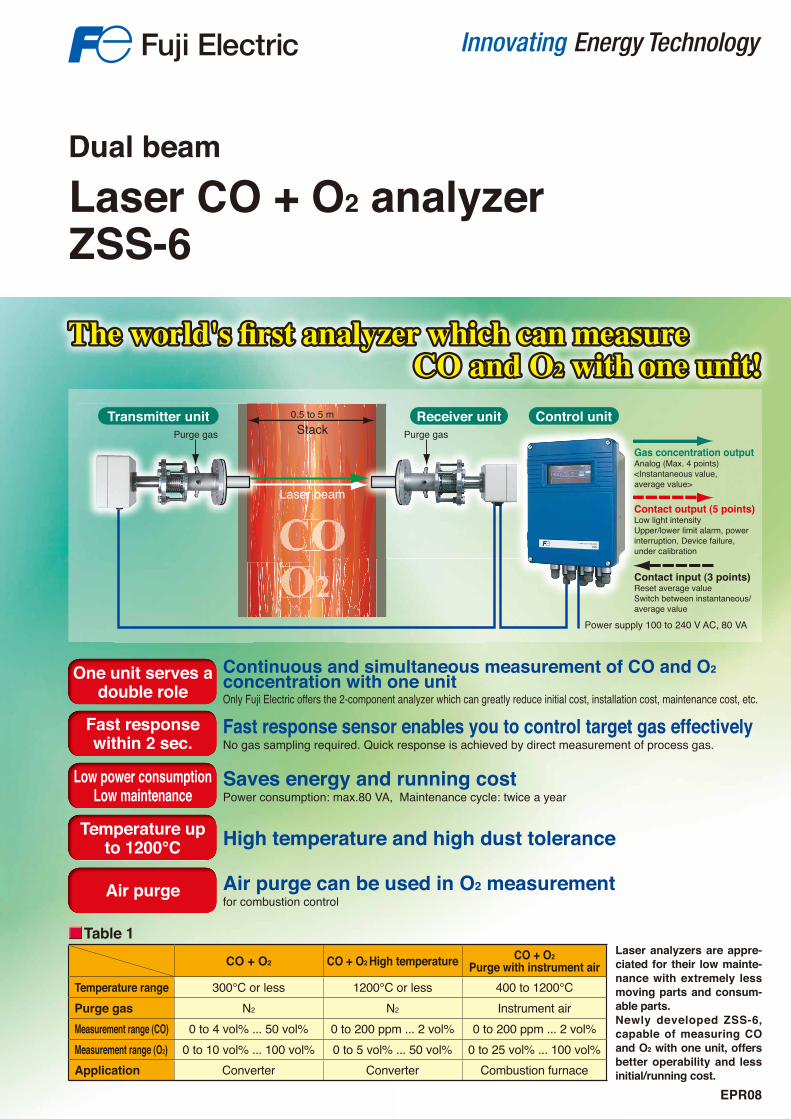
Continuous and simultaneous measurement of CO and O2concentration with one unitOnly Fuji Electric offers the 2-component analyzer which can greatly reduce initial cost, installation cost, maintenance cost, etc.
Fast response sensor enables you to control target gas effectivelyNo gas sampling required. Quick response is achieved by direct measurement of process gas.
Saves energy and running costPower consumption: max.80 VA, Maintenance cycle: twice a year
High temperature and high dust tolerance
One unit serves a double role
Fast response within 2 sec.
Low power consumption Low maintenance
Temperature upto 1200°C
Air purge Air purge can be used in O2 measurementfor combustion control
CO + O2 CO + O2 High temperature CO + O2
Purge with instrument air
Temperature range 300°C or less 1200℃ or less 400 to 1200℃Purge gas N2 N2 Instrument air
Measurement range (CO) 0 to 4 vol% ... 50 vol% 0 to 200 ppm ... 2 vol% 0 to 200 ppm ... 2 vol%
Measurement range (O2) 0 to 10 vol% ... 100 vol% 0 to 5 vol% ... 50 vol% 0 to 25 vol% ... 100 vol%
Application Converter Converter Combustion furnace
Laser analyzers are appre-ciated for their low mainte-nance with extremely less moving parts and consum-able parts.Newly developed ZSS-6, capable of measuring CO and O2 with one unit, offers better operability and less initial/running cost.
2222222
Table 1
Application examples
Outline diagram (unit: mm)
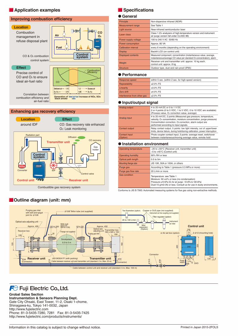
Specifi cations●GeneralPrinciple Non-dispersive infrared (NDIR)
Measurement range See Table 1
Light source Near-infrared semiconductor laser
Laser classClass 1 (O2 analyzers of high-temperature version and instrument air purge version fall under CLASS 3B)
Power supply voltage 100 to 240 V AC 50/60 Hz
Power consumption Approx. 80 VA
Calibration interval every 6 months (depending on the operating environment)
Display Backlit LCD (on control unit)
Displayed contents Measured component, concentration (instantaneous value, average,
instantaneous/average CO value per standard O2 concentration), alarm
WeightReceiver unit and transmitter unit: approx. 10 kg each,control unit: approx. 8 kg
Structure Outdoor type, dust and rain proof (IP65)
●PerformanceResponse speed within 5 sec. (within 2 sec. for high-speed version)
Repeatability ±2.0% FS
Linearity ±3.0% FS
Zero drift ±4.0% FS
Interference from other gas ±2.0% FS
● Input/output signalAnalog output 4 to 20 mA DC or 0 to 1 V DC
2 or 4 points (0 to 5 VDC, 1 to 5 VDC, 0 to 10 VDC are available)(Process value, O2 correction value, average)
Analog input4 to 20 mA DC, 2 points (Measured gas pressure, temperature, velocity, O2 concentration, moisture concentration, purge pressure)Concentration correction, O2 correction, alarm output are performed according to input signals.
Contact output Relay contact output, 5 points: low light intensity, out of upper/lower limits, device failure, during hold/during calibration, power interruption
Contact input(Option)
Photo coupler contact input, 3 points: average reset, switchover between instantaneous/moving average value, remote hold
● Installation environmentOperating temperature −20 to +55°C (Receiver unit, transmitter unit)
−5 to +45°C (Control unit)
Operating humidity 90% RH or less
Optical path length 0.5 to 5m
Mounting fl ange size JIS 10K, 50A or 100A, or others
Purge gas According to Table 1 (pressure 0.3 MPa or more)
Purge gas fl ow rate 20 L/min or more
Gas conditionTemperature: see Table 1Moisture: 50 vol% or less (no condensation)Pressure: ±10 kPa (O2 for air purge: -10 kPa to 100 kPa)Dust: 15 g/m3 (N) or less. Consult us for use in dusty environments.
Conforms to JIS B 7993: Automated measuring systems for fl ue gas using non-extractive methods.
Improving combustion effi ciency
Enhancing gas recovery effi ciency
Location
Location
Effect
Effect
Combustion management in refuse disposal plant
CO & O2 combustion
control system
Correlation between combustion effi ciency and
air-fuel ratio
Combustible gas recovery system
around IDF
Precise control of CO and O2 to ensure ideal air-fuel ratio
CO: Gas recovery rate enhancedO2: Leak monitoring
φ
φ
φ
φ φ
φ φ
φ
φ


![Pad diameters φ10 [0.394], φ15 [0.591], and φ20 [0.787 ... · Halogen-treated NBR Electroconductive silicon *Each pad can be mounted on conventional brackets. Incline Step Pad](https://img.pdfslide.us/doc/110x75/60b5666a05a6d2171840567a/pad-diameters-10-0394-15-0591-and-20-0787-halogen-treated-nbr.jpg)