Embed Size (px)
Citation preview
© 2017 IBRACON
Volume 10, Number 3 (June 2017) p. 687 – 705 • ISSN 1983-4195http://dx.doi.org/10.1590/S1983-41952017000300008
The effect of the failure of the steel roof on the facade concrete columns of a warehouse in fire. A study case
O efeito do colapso da cobertura de aço nos pilares de concreto de fachada de um depósito em situação de incêndio. Um estudo de caso
Abstract
Resumo
In many situations, the Brazilian Legislation does not require verification of roof structures in a fire, since its failure will not endanger the stability of the structure. In fire, the steel roof of an industrial building deforms by heating in geometry similar to a catenary, resulting in horizontal forces in the upper extremities of the columns. Thus, even roofs that do not constitute a frame with the columns may lead them to collapse, therefore, should be protected against fire. Due to the small dimensions of the structural elements of the roof, fire coating is uneconomical. So there is a problem in the design practice. This paper presents a procedure based on British literature, which considers the horizontal load on the columns. This horizontal load must be supported by the columns and the foundations. The aim of this paper is to detail this procedure, adapt it to Brazilian standards and apply it to a case study.
Keywords: fire, steel roof, industrial building, concrete columns.
Em muitas situações correntes, as Instruções Técnicas dos Corpos de Bombeiros e as normas brasileiras dispensam a verificação das estrutu-ras de coberturas em situação de incêndio, desde que seu colapso não prejudique a estabilidade dos pilares e dos fechamentos. Em incêndio, a cobertura de aço de um edifício industrial deforma-se pelo aquecimento, em uma geometria semelhante a uma catenária, provocando forças horizontais nas extremidades superiores dos pilares. Assim, mesmo coberturas simplesmente apoiadas que não compõem um pórtico com os pi-lares de fechamento poderão leva-los ao colapso, portanto, deveriam ser revestidas contra fogo. Devido às pequenas dimensões dos elementos estruturais da cobertura, o revestimento contra fogo é economicamente inviável, criando dessa forma um problema na prática de projeto. Este trabalho apresenta um procedimento com base em literatura britânica, em que se consideram os esforços horizontais nos pilares, que devem ser resistidos por eles e pelas fundações. O objetivo deste trabalho será detalhar esse procedimento, adaptá-lo às normas brasileiras e aplicá-lo a um estudo de caso.
Palavras-chave: incêndio, coberturas de aço, edifício industrial, pilares de concreto.
a Escola Politécnica da Universidade de São Paulo,.Sao Paulo, SP, Brasil;b Tecsteel Engenharia, São Paulo, SP, Brasil.
Received: 17 Mar 2016 • Accepted: 21 Oct 2016 • Available Online: 12 Jun 2017
I. PIERIN a
V. P. SILVA a
M. R. VARGAS b
688 IBRACON Structures and Materials Journal • 2017 • vol. 10 • nº 3
The effect of the failure of the steel roof on the facade concrete columns of a warehouse in fire. A study case
1. Introduction
Steel roof supported by reinforced concrete columns is common in industrial buildings and deposits. According to IT8 [1] and ABNT NBR 14432 [2], structural verification in fire is not required for many of these buildings, especially for the ground floor. In build-ings where the structural verification in fire is required, the roofs verification may be exempted [1] if its structural failure does not compromise the stability of the external walls or the main structure of the building. However, this verification is necessary only when there is a risk of a fire inside a building propagating to the neighbor-ing buildings [3, 4, 5, 6].If there is risk of fire spread, the structural elements must be designed so as not to collapse in the event of the building roof collapsing.In the late 1970s, the Constructional Steel Research and Devel-opment Organization (CONSTRADO) studied the steel roof col-lapse in fire. Subsequently, the Steel Construction Institute (SCI) extended these studies, which resulted in a procedure proposed by Simms and Newman [3] and adopted herein.Initially, with the increase of temperature in the framed struc-tures, the columns are deformed outwards due to the expan-sion of the beam. Later, due to the vertical deformation of the beam, the columns are drawn to the undeformed position [7]. Moreover, with increasing temperatures, the formation of plastic hinge occurs in the beam mainly due to the yielding reduction at high temperatures.As from the formation of the plastic hinge, the structural behavior of the lattice roof changes to an isostatic arch. Thus, axial efforts appear in the rafter, which, concurrently with the degradation of the material strength, cause large deformations. The frame that would initially expand out, arises a horizontal force on the top of the column, moving inwards. In this situation, the columns and the foundations must be designed to withstand these new efforts.The aim of this paper is the case study on the collapse of an in-dustrial building in fire. This study was based on the international literature cited in [3] adapted by the authors.
2. Description of the structure
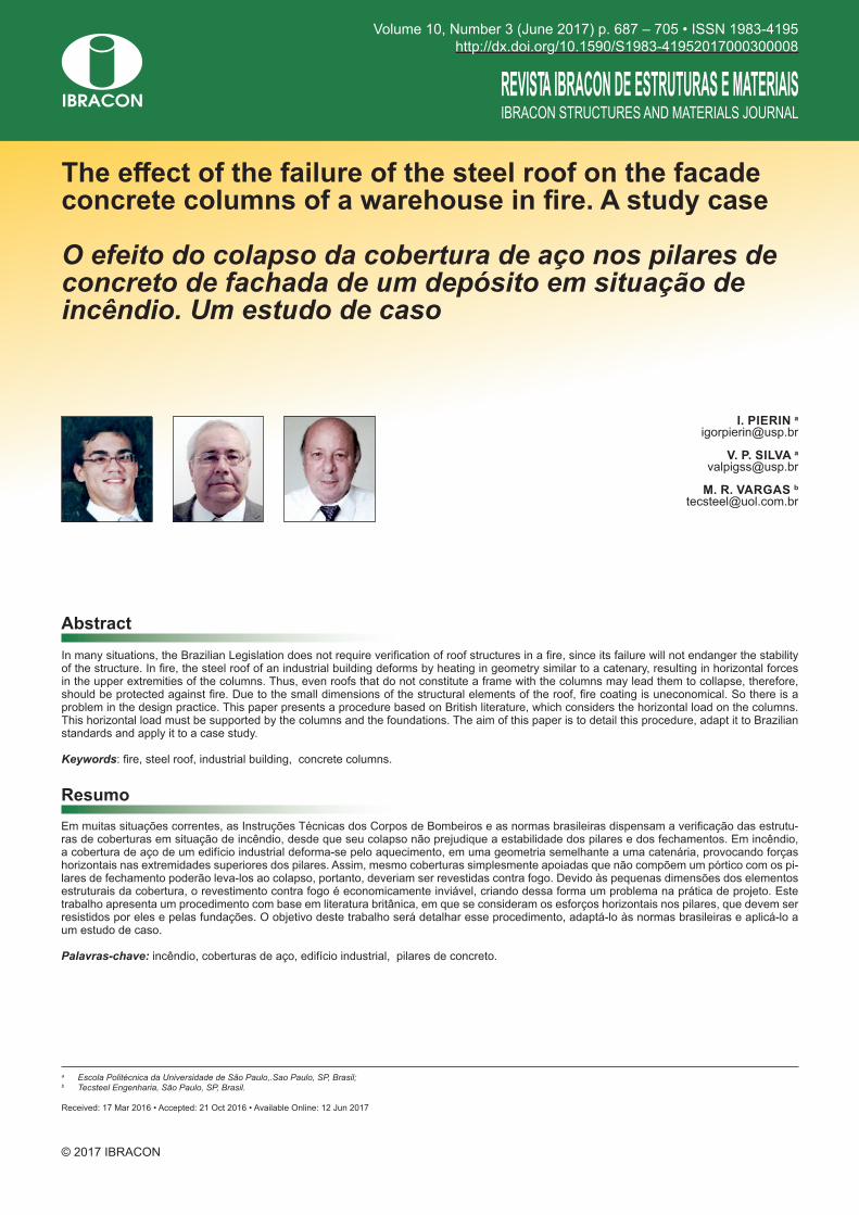
Figure 1 shows the industrial building studied in this paper. The span of the building is 20.0 m.The building roof is a steel lattice rafter supported on consoles connected to the reinforced concrete columns, as shown in Figure 2. The distance of the trusses is 9.0 m. The chords and the support verticals profiles are U 200 mm × 60 mm × 6.35 mm. The other verticals and the diagonals are composed of two equal legs of 2” × 3/16”.The cross section of the reinforced concrete column is showed in Figure 3. The length of the column is 15.0 m, the compres-sive strength of concrete is 30 MPa and the concrete cover is 3.0 cm.The lattice serves as a support to a trapezoid galvanized steel tile with insulation made of rock wool and laminated plastic. The lateral closing is made of reinforced concrete panels be-tween the columns. The thickness of the panels is 15 cm.
Figure 1Floor plan (mm)
Figure 2Transversal section (mm)
Figure 3Column cross section (mm)
689IBRACON Structures and Materials Journal • 2017 • vol. 10 • nº 3
I. PIERIN | V. P. SILVA | M. R. VARGAS
3. Procedure adopted
3.1 Overturning moment
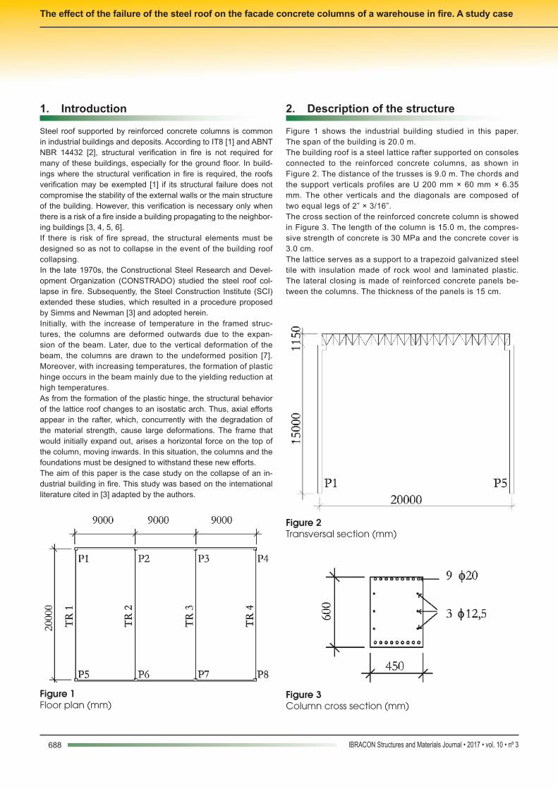
Newman [8] developed a method to determine the horizontal force that the roof rafter applies on the top of the steel column. He considered a frame formed by the columns and by the beam. Later, Simms and New-man [3] extended the method to be used in lattice rafter and trusses.It was formerly thought that the dilation of the roof structures were responsible for the collapse of the building lateral closing. Thus, there would be a horizontal force pushing the columns outwards. Currently, after the initial dilation, due to the reduction of the steel elasticity at high temperatures, the beam is known to deform. Thus, the horizontal force pulls the columns inwards.For a roof simply supported by the columns, if there is any possibil-ity of fire spreading outwards, affecting the neighboring buildings, the roof will apply a horizontal force on the columns before of the total collapse of the building. Thus, there will be necessary to apply the procedure described as follows. In simply supported roof structures, there is generally a connection between the beam and the columns. It should be verified whether the connection is able to transmit the horizontal force to the col-umns, causing the overturning moment.According to [3], the compressive members of the trusses (ties and
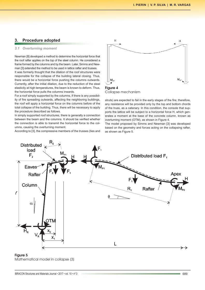
struts) are expected to fail in the early stages of the fire; therefore, any resistance will be provided only by the top and bottom chords of the truss, as a catenary. In this condition, the console that sup-ports the lattice will be subject to a horizontal force H, which gen-erates a moment at the base of the concrete column, known as overturning moment (OTM), as shown in Figure 4. The model proposed by Simms and Newman [3] was developed based on the geometry and forces acting on the collapsing rafter, as shown as Figure 5.
Figure 4Collapse mechanism
Figure 5Mathematical model in collapse [3]
690 IBRACON Structures and Materials Journal • 2017 • vol. 10 • nº 3
The effect of the failure of the steel roof on the facade concrete columns of a warehouse in fire. A study case
In Figure 5, R1 is the length from end of the haunch to the apex, R2 is the haunch length from the center line of the column, Y is the height of end haunch, F1 is the vertical load on rafter length R1, F2 is the vertical load on rafter length R2, Vr and Hr are the vertical and the horizontal reactions on the column base, H is the resulting horizontal load on rafter length R1, MP1 and MP2 are the fire hinge moment at the end of the haunch and at the apex, respectively, and is the rafter sag.Considering the vertical equilibrium, the vertical reaction on the column base is given by equation (1).
(1)
Taking moments of the apex, force H is given by equation (2).
(2)
Due to the failure mode of the trusses, the residual moments in the rafter is assumed to be zero and the haunch length is also equal zero [3]. Furthermore, as this method ignores the bending of the chords of the trusses, the magnitude of the overturning moment will be expected to be higher than the overturning moment for por-tal frames.Thus, the overturning moment is given by equation (3), which is greater than 10% of the plastic capacity of the column [3].
(3)The vertical force on the main rafter (F1) is given by equation (4).
(4)
In equation (4), wf is the factored load in fire, S is the frame spacing and L is the span.Considering the self-weight of the lateral closing (WD), the vertical reaction is obtained by equation (5).
(5)Substituting equation (4) into (2) and considering the failure mode of the trusses, horizontal force H is obtained on the top of the col-umn by of equation (6).
(6)
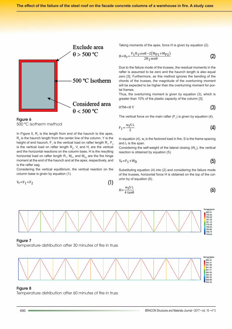
Figure 6500 ºC isotherm method
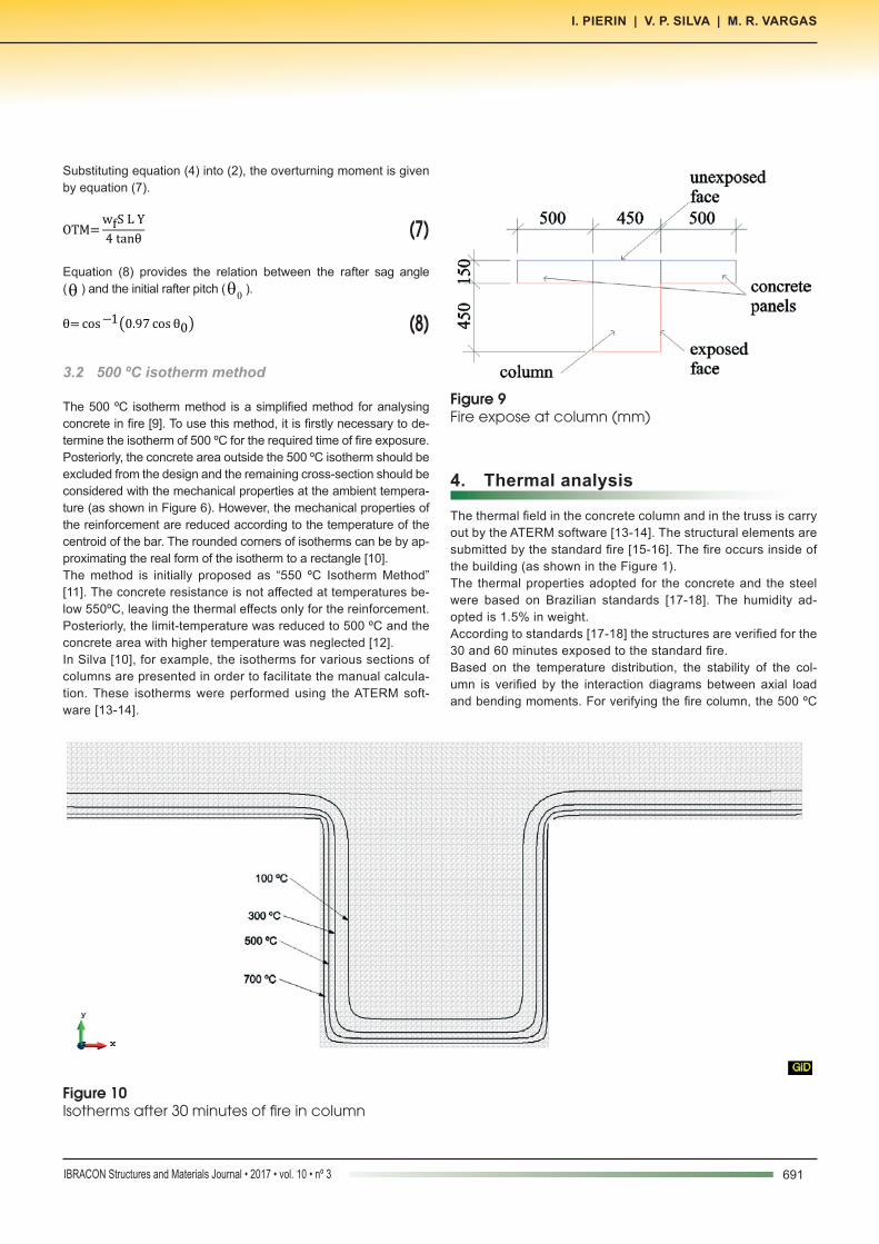
Figure 7Temperature distribution after 30 minutes of fire in truss
Figure 8Temperature distribution after 60 minutes of fire in truss
691IBRACON Structures and Materials Journal • 2017 • vol. 10 • nº 3
I. PIERIN | V. P. SILVA | M. R. VARGAS
Substituting equation (4) into (2), the overturning moment is given by equation (7).
(7)
Equation (8) provides the relation between the rafter sag angle (θ ) and the initial rafter pitch ( 0θ ).
(8)
3.2 500 ºC isotherm method
The 500 ºC isotherm method is a simplified method for analysing concrete in fire [9]. To use this method, it is firstly necessary to de-termine the isotherm of 500 ºC for the required time of fire exposure. Posteriorly, the concrete area outside the 500 ºC isotherm should be excluded from the design and the remaining cross-section should be considered with the mechanical properties at the ambient tempera-ture (as shown in Figure 6). However, the mechanical properties of the reinforcement are reduced according to the temperature of the centroid of the bar. The rounded corners of isotherms can be by ap-proximating the real form of the isotherm to a rectangle [10].The method is initially proposed as “550 ºC Isotherm Method” [11]. The concrete resistance is not affected at temperatures be-low 550ºC, leaving the thermal effects only for the reinforcement. Posteriorly, the limit-temperature was reduced to 500 ºC and the concrete area with higher temperature was neglected [12].In Silva [10], for example, the isotherms for various sections of columns are presented in order to facilitate the manual calcula-tion. These isotherms were performed using the ATERM soft-ware [13-14].
4. Thermal analysis
The thermal field in the concrete column and in the truss is carry out by the ATERM software [13-14]. The structural elements are submitted by the standard fire [15-16]. The fire occurs inside of the building (as shown in the Figure 1).The thermal properties adopted for the concrete and the steel were based on Brazilian standards [17-18]. The humidity ad-opted is 1.5% in weight.According to standards [17-18] the structures are verified for the 30 and 60 minutes exposed to the standard fire.Based on the temperature distribution, the stability of the col-umn is verified by the interaction diagrams between axial load and bending moments. For verifying the fire column, the 500 ºC
Figure 9Fire expose at column (mm)
Figure 10Isotherms after 30 minutes of fire in column

692 IBRACON Structures and Materials Journal • 2017 • vol. 10 • nº 3
The effect of the failure of the steel roof on the facade concrete columns of a warehouse in fire. A study case
isotherm method will be used as recommended in Eurocode 2 [9].
4.1 Trusses
Due the symmetry, only half of the truss was thermally analyzed. All the truss components were exposed to the standard fire. Fig-ures 7 and 8 show the temperatures distribution for the 30 and 60 minutes of fire. The thermal analyses were carried out by the ATERM software [14-15].The temperature distribution after 30 and 60 minutes of fire is was observed to be practically uniform.
4.2 Columns
The thermal analysis of the concrete columns was carried out by the ATERM software [14-15].
The thermal model used includes the column and a concrete panel with 50 cm in length on each side of the column, as shown in Figure 9. The internal sides of the column and the panel were exposed to the standard fire. The thermal parameters adopted in the analyses are indicated in ABNT NBR 15200 [17]. The out-side of the building was exposed to ambient temperature, and the combined phenomena of convection and radiation was simulated by a convection coefficient equal to 9 W/m² °C. The model was discretized into 8400 triangular elements with 1 cm in side.Figures 10 and 11 show the isotherms after 30 and 60 minutes of standard fire.
5. Actions
According to ABNT NBR 8681 [19], for the exceptional actions combination, the normal design force is given by equation (9),
Figure 11Isotherms after 60 minutes of fire in column
Figure 12Reduction section by the 500 ºC isotherm after (a) 30 minutes (b) 60 minutes
B BA B

693IBRACON Structures and Materials Journal • 2017 • vol. 10 • nº 3
I. PIERIN | V. P. SILVA | M. R. VARGAS
(9) where γg is the permanent action coefficient and is 1.2 for the exceptional combination, gF are the permanent loads, γq is the variable load coefficient and is a unitary, q,excF are the excep-tional actions, qF are the variable loads and ψ2 is the reduction factor, which is 0.6 for the deposits [20]. For the exceptional combination, the ψ2 factor can be multiplied by 0.7 when the principal load is the fire [19].The major influence area of the column is 90 m² (see Figure 1). The column height is 15 m. A self-weight of the roof equal to 0.5 kN/m² was admitted and the live load is 0.25 kN/m²; thus, the design normal force in the column is given by equation 10.
(10)In the exceptional combination, the reduction factor (ψ2) for the wind is zero [19]. However, when the structural members are submitted only to wind actions, in addition to the self-weight and any thermal actions, the reduction factor should be 0.2 [18]. In this study, the efforts acting on the column are the dead load and the thermal action caused by the lattice and not by the column. Thus, on the safety side, the reduction factor equal to 0.2 will be used. In addition, the wind exerts a pressure
equal to 0.7 kN/m², with an external pressure coefficient equal to 0.7. Thus, the wind causes a moment on the column base is 90.0 kN.m.In this situation, the truss console is submitted to a horizontal force H, which causes an overturning moment OTM on the column base.In fire, the weight of the roof steel is 0.07 kN/m² and the weight of the lattice rafter and the purling is 0.15 kN/m². Thus, the collapse load (wf) is 0.22 kN/m². Note that, in a fire, the roof cladding materi-als are consumed.By the equation (6) and by the building geometry (see Figure 1), horizontal force H is 39.5 kN and moment OTM is 592.5 kN.m.By equation (5), the vertical reaction in fire is 526.05 kN.
6. Column structural verification
In fire, the concrete structures can be verified by the 500 ºC Iso-therm Method [9]. This method assumes that only the concrete area with temperatures below 500 ºC contributes to the strength capacity of the structural element. The concrete within the 500 ºC isotherm is considered to have the same mechanical properties at ambient temperature; however, the safety coefficients are uni-tary. The concrete area above 500 ºC is despised. The mechanical properties of the reinforcement are reduced according to the tem-perature at the bar centroid obtained by thermal analysis.The interaction diagram between the normal force and the bend-ing moments (Mx and My) is carried out by the CFF program,
Table 1Coordinates and temperatures of the reinforcements
Bar Coordinate X (cm)
Coordinate Y (cm) Diameter (mm) Temperature
30 min (ºC)Temperature 60 min (ºC)
1 4 56 20 20.8 31.3
2 8.625 56 20 20.1 23.9
3 13.25 56 20 20 20.8
4 17.875 56 20 20 20.1
5 22.5 56 20 20 20
6 27.125 56 20 20 20.1
7 31.75 56 20 20 20.8
8 36.375 56 20 20.1 23.9
9 41 56 20 20.8 31.3
10 4 45 12.5 130.7 254.8
11 4 30 12.5 184.6 354.5
12 4 15 12.5 184.7 356.5
13 4 4 20 311.2 563.2
14 8.625 4 20 193.1 394.5
15 13.25 4 20 184.9 359.5
16 17.875 4 20 184.6 354.9
17 22.5 4 20 184.6 354.5
18 27.125 4 20 184.6 354.9
19 31.75 4 20 184.9 359.5
20 36.375 4 20 193.1 394.5
21 41 4 20 311.2 563.2
22 41 15 12.5 184.7 356.5
23 41 30 12.5 184.6 354.5
24 41 45 12.5 130.7 254.8
694 IBRACON Structures and Materials Journal • 2017 • vol. 10 • nº 3
The effect of the failure of the steel roof on the facade concrete columns of a warehouse in fire. A study case
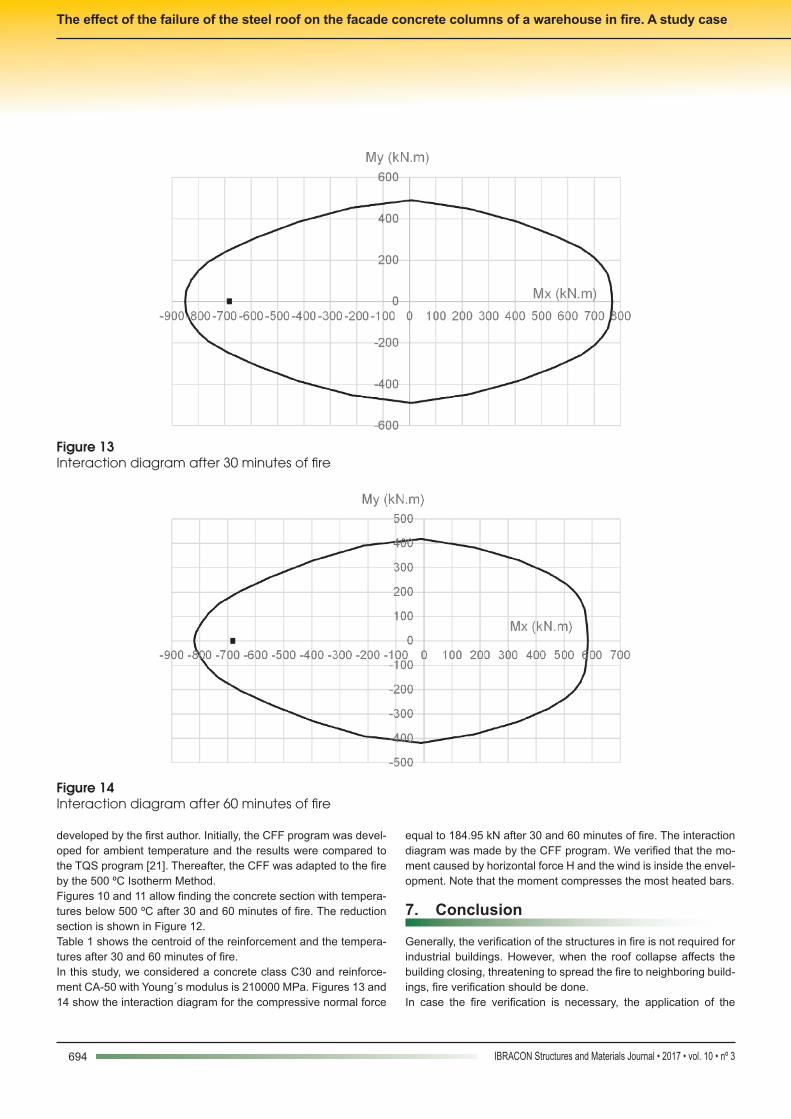
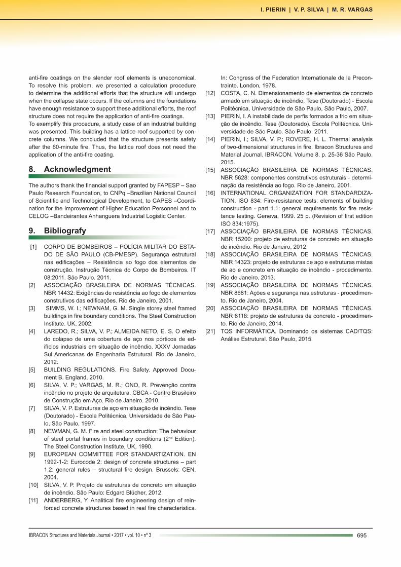
developed by the first author. Initially, the CFF program was devel-oped for ambient temperature and the results were compared to the TQS program [21]. Thereafter, the CFF was adapted to the fire by the 500 ºC Isotherm Method.Figures 10 and 11 allow finding the concrete section with tempera-tures below 500 ºC after 30 and 60 minutes of fire. The reduction section is shown in Figure 12.Table 1 shows the centroid of the reinforcement and the tempera-tures after 30 and 60 minutes of fire.In this study, we considered a concrete class C30 and reinforce-ment CA-50 with Young´s modulus is 210000 MPa. Figures 13 and 14 show the interaction diagram for the compressive normal force
equal to 184.95 kN after 30 and 60 minutes of fire. The interaction diagram was made by the CFF program. We verified that the mo-ment caused by horizontal force H and the wind is inside the envel-opment. Note that the moment compresses the most heated bars.
7. Conclusion
Generally, the verification of the structures in fire is not required for industrial buildings. However, when the roof collapse affects the building closing, threatening to spread the fire to neighboring build-ings, fire verification should be done. In case the fire verification is necessary, the application of the
Figure 13Interaction diagram after 30 minutes of fire
Figure 14Interaction diagram after 60 minutes of fire
695IBRACON Structures and Materials Journal • 2017 • vol. 10 • nº 3
I. PIERIN | V. P. SILVA | M. R. VARGAS
anti-fire coatings on the slender roof elements is uneconomical. To resolve this problem, we presented a calculation procedure to determine the additional efforts that the structure will undergo when the collapse state occurs. If the columns and the foundations have enough resistance to support these additional efforts, the roof structure does not require the application of anti-fire coatings.To exemplify this procedure, a study case of an industrial building was presented. This building has a lattice roof supported by con-crete columns. We concluded that the structure presents safety after the 60-minute fire. Thus, the lattice roof does not need the application of the anti-fire coating.
8. Acknowledgment
The authors thank the financial support granted by FAPESP – Sao Paulo Research Foundation, to CNPq –Brazilian National Council of Scientific and Technological Development, to CAPES –Coordi-nation for the Improvement of Higher Education Personnel and to CELOG –Bandeirantes Anhanguera Industrial Logistic Center. 9. Bibliografy
[1] CORPO DE BOMBEIROS – POLÍCIA MILITAR DO ESTA-DO DE SÃO PAULO (CB-PMESP). Segurança estrutural nas edificações – Resistência ao fogo dos elementos de construção. Instrução Técnica do Corpo de Bombeiros. IT 08:2011. São Paulo. 2011.
[2] ASSOCIAÇÃO BRASILEIRA DE NORMAS TÉCNICAS. NBR 14432: Exigências de resistência ao fogo de elementos construtivos das edificações. Rio de Janeiro, 2001.
[3] SIMMS, W. I.; NEWNAM, G. M. Single storey steel framed buildings in fire boundary conditions. The Steel Construction Institute. UK, 2002.
[4] LAREDO, R.; SILVA, V. P.; ALMEIDA NETO, E. S. O efeito do colapso de uma cobertura de aço nos pórticos de ed-ifícios industriais em situação de incêndio. XXXV Jornadas Sul Americanas de Engenharia Estrutural. Rio de Janeiro, 2012.
[5] BUILDING REGULATIONS. Fire Safety. Approved Docu-ment B. England, 2010.
[6] SILVA, V. P.; VARGAS, M. R.; ONO, R. Prevenção contra incêndio no projeto de arquitetura. CBCA - Centro Brasileiro de Construção em Aço. Rio de Janeiro. 2010.
[7] SILVA, V. P. Estruturas de aço em situação de incêndio. Tese (Doutorado) - Escola Politécnica, Universidade de São Pau-lo, São Paulo, 1997.
[8] NEWMAN, G. M. Fire and steel construction: The behaviour of steel portal frames in boundary conditions (2nd Edition).The Steel Construction Institute, UK, 1990.
[9] EUROPEAN COMMITTEE FOR STANDARTIZATION. EN 1992-1-2: Eurocode 2: design of concrete structures – part 1.2: general rules – structural fire design. Brussels: CEN, 2004.
[10] SILVA, V. P. Projeto de estruturas de concreto em situação de incêndio. São Paulo: Edgard Blücher, 2012.
[11] ANDERBERG, Y. Analitical fire engineering design of rein-forced concrete structures based in real fire characteristics.
In: Congress of the Federation Internationale de la Precon-trainte. London, 1978.
[12] COSTA, C. N. Dimensionamento de elementos de concreto armado em situação de incêndio. Tese (Doutorado) - Escola Politécnica, Universidade de São Paulo, São Paulo, 2007.
[13] PIERIN, I. A instabilidade de perfis formados a frio em situa-ção de incêndio. Tese (Doutorado). Escola Politécnica. Uni-versidade de São Paulo. São Paulo. 2011.
[14] PIERIN, I.; SILVA, V. P.; ROVERE, H. L. Thermal analysis of two-dimensional structures in fire. Ibracon Structures and Material Journal. IBRACON. Volume 8. p. 25-36 São Paulo. 2015.
[15] ASSOCIAÇÃO BRASILEIRA DE NORMAS TÉCNICAS. NBR 5628: componentes construtivos estruturais - determi-nação da resistência ao fogo. Rio de Janeiro, 2001.
[16] INTERNATIONAL ORGANIZATION FOR STANDARDIZA-TION. ISO 834: Fire-resistance tests: elements of building construction - part 1.1: general requirements for fire resis-tance testing. Geneva, 1999. 25 p. (Revision of first edition ISO 834:1975).
[17] ASSOCIAÇÃO BRASILEIRA DE NORMAS TÉCNICAS. NBR 15200: projeto de estruturas de concreto em situação de incêndio. Rio de Janeiro, 2012.
[18] ASSOCIAÇÃO BRASILEIRA DE NORMAS TÉCNICAS. NBR 14323: projeto de estruturas de aço e estruturas mistas de ao e concreto em situação de incêndio - procedimento. Rio de Janeiro, 2013.
[19] ASSOCIAÇÃO BRASILEIRA DE NORMAS TÉCNICAS. NBR 8681: Ações e segurança nas estruturas - procedimen-to. Rio de Janeiro, 2004.
[20] ASSOCIAÇÃO BRASILEIRA DE NORMAS TÉCNICAS. NBR 6118: projeto de estruturas de concreto - procedimen-to. Rio de Janeiro, 2014.
[21] TQS INFORMÁTICA. Dominando os sistemas CAD/TQS: Análise Estrutural. São Paulo, 2015.