Embed Size (px)
Citation preview
Skip to main content Skip to primary navigation
Menu
Home HomeAbout this portalLatest updates
Print Save EmailResource detailCitations
NZS 3604:2011 Timber-framed buildings
Table of Contents
View on Information Provider website Download this resource (PDF, 11.4MB) {{ linkText }}
AbbreviationNZS 3604:2011
Valid from13/02/2011
ReplacesNZS 3604:1999
Information providerStandards New Zealand
AuthorStandards New Zealand
Information typeNew Zealand Standard
FormatPDF
Cited ByThis resource is cited by 56 documents (show Citations)
CitesThis resource cites 49 documents (show Citations)
Description
Provides methods and details for the design and construction of timber-framed structures not requiring specific engineeringdesign. This Standard applies to residential buildings up to three-storeys high including multi-residential buildings, somecommercial buildings and freestanding, uninhabited garages.
Scope
NZS 3604 sets down construction requirements for timber framed buildings within the limitations specified in 1.1.2.NZS 3604applies only to buildings within the following limitations (this is not a complete list):
(a) Buildings shall be founded on good ground;(b) Buildings shall be Category IV or V buildings (see table 1.1). Buildings not covered by this Standard are those withoutexternal walls, such as free standing carports and pergolas;(c) The total height from the lowest ground level to the highest point of the roof shall not exceed 10 m;(d) The design snow load shall be not greater than 1 kPa, as determined from section 15;(e) Buildings shall have uses comprising:
(i) Domestic;
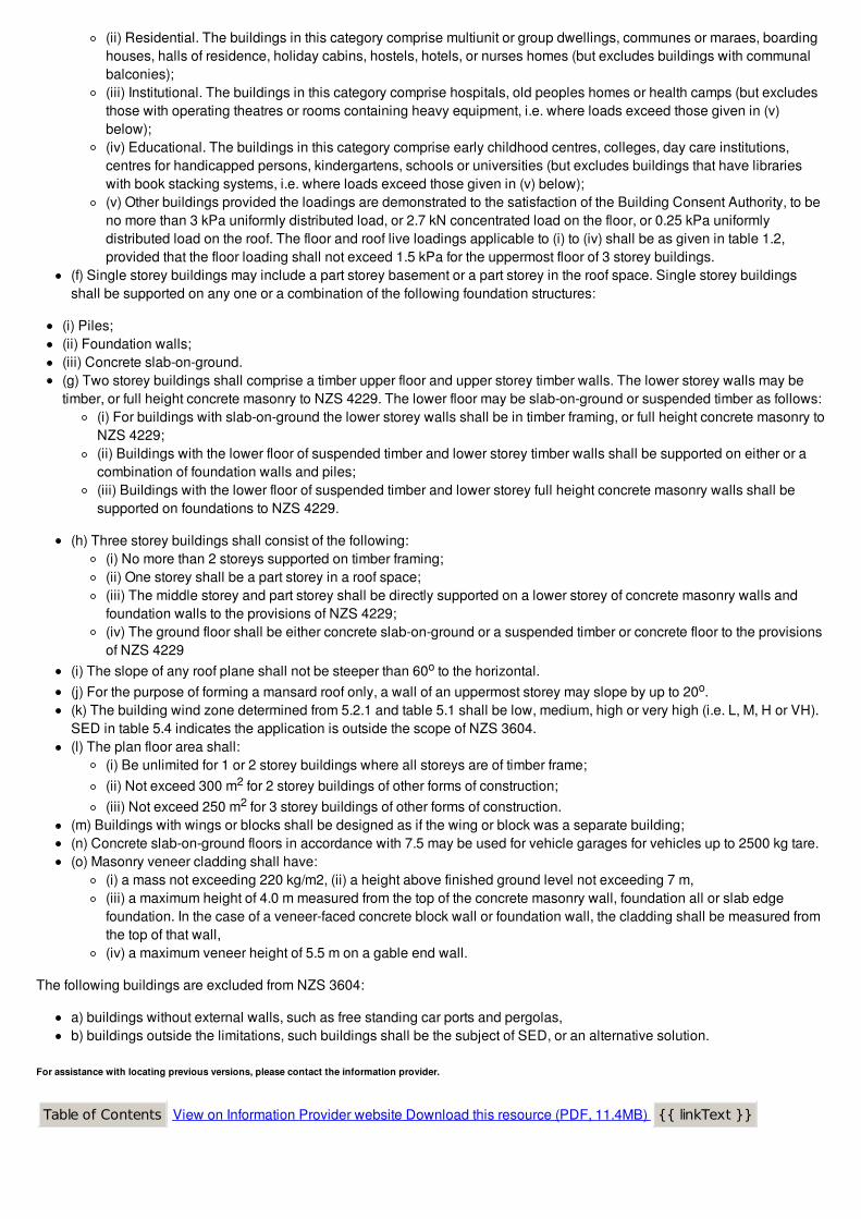
(ii) Residential. The buildings in this category comprise multiunit or group dwellings, communes or maraes, boardinghouses, halls of residence, holiday cabins, hostels, hotels, or nurses homes (but excludes buildings with communalbalconies);(iii) Institutional. The buildings in this category comprise hospitals, old peoples homes or health camps (but excludesthose with operating theatres or rooms containing heavy equipment, i.e. where loads exceed those given in (v)below);(iv) Educational. The buildings in this category comprise early childhood centres, colleges, day care institutions,centres for handicapped persons, kindergartens, schools or universities (but excludes buildings that have librarieswith book stacking systems, i.e. where loads exceed those given in (v) below);(v) Other buildings provided the loadings are demonstrated to the satisfaction of the Building Consent Authority, to beno more than 3 kPa uniformly distributed load, or 2.7 kN concentrated load on the floor, or 0.25 kPa uniformlydistributed load on the roof. The floor and roof live loadings applicable to (i) to (iv) shall be as given in table 1.2,provided that the floor loading shall not exceed 1.5 kPa for the uppermost floor of 3 storey buildings.
(f) Single storey buildings may include a part storey basement or a part storey in the roof space. Single storey buildingsshall be supported on any one or a combination of the following foundation structures:
(i) Piles;(ii) Foundation walls;(iii) Concrete slab-on-ground.(g) Two storey buildings shall comprise a timber upper floor and upper storey timber walls. The lower storey walls may betimber, or full height concrete masonry to NZS 4229. The lower floor may be slab-on-ground or suspended timber as follows:
(i) For buildings with slab-on-ground the lower storey walls shall be in timber framing, or full height concrete masonry toNZS 4229;(ii) Buildings with the lower floor of suspended timber and lower storey timber walls shall be supported on either or acombination of foundation walls and piles;(iii) Buildings with the lower floor of suspended timber and lower storey full height concrete masonry walls shall besupported on foundations to NZS 4229.
(h) Three storey buildings shall consist of the following:(i) No more than 2 storeys supported on timber framing;(ii) One storey shall be a part storey in a roof space;(iii) The middle storey and part storey shall be directly supported on a lower storey of concrete masonry walls andfoundation walls to the provisions of NZS 4229;(iv) The ground floor shall be either concrete slab-on-ground or a suspended timber or concrete floor to the provisionsof NZS 4229
(i) The slope of any roof plane shall not be steeper than 60o to the horizontal.(j) For the purpose of forming a mansard roof only, a wall of an uppermost storey may slope by up to 20o.(k) The building wind zone determined from 5.2.1 and table 5.1 shall be low, medium, high or very high (i.e. L, M, H or VH).SED in table 5.4 indicates the application is outside the scope of NZS 3604.(l) The plan floor area shall:
(i) Be unlimited for 1 or 2 storey buildings where all storeys are of timber frame;(ii) Not exceed 300 m2 for 2 storey buildings of other forms of construction;(iii) Not exceed 250 m2 for 3 storey buildings of other forms of construction.
(m) Buildings with wings or blocks shall be designed as if the wing or block was a separate building;(n) Concrete slab-on-ground floors in accordance with 7.5 may be used for vehicle garages for vehicles up to 2500 kg tare.(o) Masonry veneer cladding shall have:
(i) a mass not exceeding 220 kg/m2, (ii) a height above finished ground level not exceeding 7 m,(iii) a maximum height of 4.0 m measured from the top of the concrete masonry wall, foundation all or slab edgefoundation. In the case of a veneer-faced concrete block wall or foundation wall, the cladding shall be measured fromthe top of that wall,(iv) a maximum veneer height of 5.5 m on a gable end wall.
The following buildings are excluded from NZS 3604:
a) buildings without external walls, such as free standing car ports and pergolas,b) buildings outside the limitations, such buildings shall be the subject of SED, or an alternative solution.
For assistance with locating previous versions, please contact the information provider.
Table of Contents View on Information Provider website Download this resource (PDF, 11.4MB) {{ linkText }}
For assistance with locating previous versions, please contact the information provider.
This resource is cited by:
NZS 3604:2011 Timber-framed buildings
This document is CITED BY:
B1/AS1 (First edition, amendment 15)
NZS 3604:2011 is cited by Acceptable Solution B1/AS1: General from 19/05/2011
B1/AS1 (First Edition, Amendment 18)
NZS 3604:2011 is cited by Acceptable Solution B1/AS1: General from 19/05/2011
B1/AS1 (First edition, Amendment 13)
NZS 3604:2011 is cited by Acceptable Solution B1/AS1: General from 19/05/2011
B1/AS1 (First Edition, Amendment 17)
NZS 3604:2011 is cited by Acceptable Solution B1/AS1: General from 19/05/2011
B1/AS1 (First edition, Amendment 12)
NZS 3604:2011 is cited by Acceptable Solution B1/AS1: General from 19/05/2011
B1/AS1 (First edition, Amendment 16)
NZS 3604:2011 is cited by Acceptable Solution B1/AS1: General from 19/05/2011
B1/AS1 (First edition, Amendment 14)
NZS 3604:2011 is cited by Acceptable Solution B1/AS1: General from 19/05/2011
B1/AS1 (First edition, Amendment 11)
NZS 3604:2011 is cited by Acceptable Solution B1/AS1: General
B1/AS1 (First edition, Amendment 10)
NZS 3604:2011 is cited by Acceptable Solution B1/AS1: General from 01/04/2007
B1/AS3 (First Edition, Amendment 17)
NZS 3604:2011 is cited by Acceptable Solution B1/AS3: Small Chimneys from 19/05/2011
B1/AS3 (First edition, Amendment 16)
NZS 3604:2011 is cited by Acceptable Solution B1/AS3: Small Chimneys from 19/05/2011
B1/AS3 (First edition, Amendment 12)
NZS 3604:2011 is cited by Acceptable Solution B1/AS3: Small Chimneys from 19/05/2011
B1/AS3 (First Edition, Amendment 18)
NZS 3604:2011 is cited by Acceptable Solution B1/AS3: Small Chimneys from 19/05/2011
B1/AS3 (First edition, amendment 15)
NZS 3604:2011 is cited by Acceptable Solution B1/AS3: Small Chimneys from 19/05/2011
B1/AS3 (First edition, Amendment 14)
NZS 3604:2011 is cited by Acceptable Solution B1/AS3: Small Chimneys from 19/05/2011
B1/AS3 (First Edition, Amendment 11)
NZS 3604:2011 is cited by Acceptable Solution B1/AS3: Small Chimneys from 19/05/2011
B1/AS3 (First edition, Amendment 13)
NZS 3604:2011 is cited by Acceptable Solution B1/AS3: Small Chimneys from 19/05/2011
B2/AS1 (Second edition, Amendment 8)
NZS 3604:2011 is cited by Acceptable Solution B2/AS1: Durability from 01/07/2001
B2/AS1 (Second Edition, Amendment 10)
NZS 3604:2011 is cited by Acceptable Solution B2/AS1: Durability from 14/04/2014
B2/AS1 (Second edition, Amendment 9)
NZS 3604:2011 is cited by Acceptable Solution B2/AS1: Durability from 14/04/2014
B2/AS1 (Second Edition, Amendment 11)
NZS 3604:2011 is cited by Acceptable Solution B2/AS1: Durability from 14/04/2014
E1/AS1 (First Edition, Amendment 9)
NZS 3604:2011 is cited by Acceptable Solution E1/AS1: Surface Water from 10/10/2011
E1/AS1 (First Edition, Amendment 10)
NZS 3604:2011 is cited by Acceptable Solution E1/AS1: Surface Water from 30/09/2010
E2/AS1 (Third Edition, Amendment 7)
NZS 3604:2011 is cited by Acceptable Solution E2/AS1: External Moisture from 11/08/2001
E2/AS1 (Third Edition, Amendment 5, Errata 2)
NZS 3604:2011 is cited by Acceptable Solution E2/AS1: External Moisture from 11/08/2001
E2/AS1 (Third Edition, Amendment 9)
NZS 3604:2011 is cited by Acceptable Solution E2/AS1: External Moisture from 11/08/2001
E2/AS1 (Third Edition, Amendment 5)
NZS 3604:2011 is cited by Acceptable Solution E2/AS1: External Moisture from 11/08/2001
E2/AS1 (Third Edition, Amendment 8)
NZS 3604:2011 is cited by Acceptable Solution E2/AS1: External Moisture from 11/08/2001
E2/AS1 (Third Edition, Amendment 6)
NZS 3604:2011 is cited by Acceptable Solution E2/AS1: External Moisture from 11/08/2001
E2/AS2 (Third Edition, Amendment 6)
NZS 3604:2011 is cited by Acceptable Solution E2/AS2: Earth buildings from 01/08/2011
E2/AS2 (Third Edition, Amendment 8)
NZS 3604:2011 is cited by Acceptable Solution E2/AS2: Earth buildings from 01/08/2011
E2/AS2 (Third Edition, Amendment 5, Errata 2)
NZS 3604:2011 is cited by Acceptable Solution E2/AS2: Earth buildings from 01/08/2011
E2/AS2 (Third Edition, Amendment 5)
NZS 3604:2011 is cited by Acceptable Solution E2/AS2: Earth buildings from 01/08/2011
E2/AS2 (Third edition, amendment 7)
NZS 3604:2011 is cited by Acceptable Solution E2/AS2: Earth buildings from 01/08/2011
E2/AS2 (Third Edition, Amendment 9)
NZS 3604:2011 is cited by Acceptable Solution E2/AS2: Earth buildings from 01/08/2011
G12/AS2 (Third Edition, Amendment 9)
NZS 3604:2011 is cited by Acceptable Solution G12/AS2: Solar Water Heaters from 10/10/2011
G12/AS2 (Third Edition, Amendment 10)
NZS 3604:2011 is cited by Acceptable Solution G12/AS2: Solar Water Heaters from 10/10/2011
G12/AS2 (Third Edition, Amendment 12)
NZS 3604:2011 is cited by Acceptable Solution G12/AS2: Solar Water Heaters from 10/10/2011
G12/AS2 (Third Edition, Amendment 8)
NZS 3604:2011 is cited by Acceptable Solution G12/AS2: Solar Water Heaters from 10/10/2011
G12/AS2 (Third Edition, Amendment 11)
NZS 3604:2011 is cited by Acceptable Solution G12/AS2: Solar Water Heaters from 10/10/2011
G13/AS2 (Second Edition, Amendment 6)
NZS 3604:2011 is cited by Acceptable Solution G13/AS2: Drainage from 14/02/2014
G13/AS2 (Second Edition, Amendment 8)
NZS 3604:2011 is cited by Acceptable Solution G13/AS2: Drainage from 14/02/2014
G13/AS2 (Second Edition, Amendment 5)
NZS 3604:2011 is cited by Acceptable Solution G13/AS2: Drainage from 14/02/2014
G13/AS2 (Second Edition, Amendment 7)
NZS 3604:2011 is cited by Acceptable Solution G13/AS2: Drainage from 14/02/2014
E2/VM1 (Third Edition, Amendment 7)
NZS 3604:2011 is cited by Verification Method E2/VM1: External Moisture from 01/08/2011
E2/VM1 (Third Edition, Amedment 5, Errata 2)
NZS 3604:2011 is cited by Verification Method E2/VM1: External Moisture from 01/08/2011
E2/VM1 (Third Edition, Amendment 9)
NZS 3604:2011 is cited by Verification Method E2/VM1: External Moisture from 01/08/2011
E2/VM1 (Third Edition, Amendment 8)
NZS 3604:2011 is cited by Verification Method E2/VM1: External Moisture from 01/08/2011
E2/VM1 (Third Edition, Amendment 5)
NZS 3604:2011 is cited by Verification Method E2/VM1: External Moisture from 01/08/2011
E2/VM1 (Third Edition, Amendment 6)
NZS 3604:2011 is cited by Verification Method E2/VM1: External Moisture from 01/08/2011
AS/NZS 1748.1:2011
NZS 3604:2011 is cited by AS/NZS 1748.1:2011 Timber - Solid - Stress-graded for structural purposes - Generalrequirements
BRANZ EM6 2011
NZS 3604:2011 is cited by BRANZ Evaluation Method EM6 2011 - Test and evaluation procedure for window and doorsupports
CP01:2011 (Errata 1 January 2015)
NZS 3604:2011 is cited by Code of Practice for Weathertight Concrete and Concrete Masonry Construction
NASH Standard Part 1:2016
NZS 3604:2011 is cited by NASH Standard Part 1:2016 Design Criteria - Alternative Solution
NASH Standard Part 2:2019
NZS 3604:2011 is cited by NASH Standard Part 2:2019 Light Steel Framed Buildings.
NZS 4229:2013
NZS 3604:2011 is cited by NZS 4229:2013 Concrete masonry buildings not requiring specific engineering design
Back
NZS 3604:2011 Timber-framed buildings
Show what documents this resource is CITED BY Show what documents this resource CITES
Description
Provides methods and details for the design and construction of timber-framed structures not requiring specific engineeringdesign. This Standard applies to residential buildings up to three-storeys high including multi-residential buildings, somecommercial buildings and freestanding, uninhabited garages.
View on Information Provider website Download this resource (PDF, 11.4MB)
NZS 3604:2011 Timber-framed buildings
Description
Provides methods and details for the design and construction of timber-framed structures not requiring specific engineeringdesign. This Standard applies to residential buildings up to three-storeys high including multi-residential buildings, somecommercial buildings and freestanding, uninhabited garages.
View on Information Provider website Download this resource (PDF, 11.4MB)
This resource cites:
NZS 3604:2011 Timber-framed buildings
This document CITES:
New Zealand Standards
AS/NZS 1170.0:2002
NZS 3604:2011 cites AS/NZS 1170.0:2002 Structural Design Actions - General principles
AS/NZS 1170.1:2002
NZS 3604:2011 cites AS/NZS 1170.1:2002 (R2016) Structural Design Actions - Permanent, imposed and other actions
AS/NZS 1170.2:2002
NZS 3604:2011 cites AS/NZS 1170.2:2002 Structural Design Actions - Wind Actions
AS/NZS 1170.3 Supplement 1:2003
NZS 3604:2011 cites AS/NZS 1170.3 Supplement 1:2003 Structural design actions - Part 3: Snow and ice actions -Commentary (Supplement to AS/NZS 1170.3:2003)
AS/NZS 1170.3:2003 (Reconfirmed in 2016)
NZS 3604:2011 cites AS/NZS 1170.3:2003 Structural Design Actions - Snow and ice actions
AS/NZS 1328.1:1998
NZS 3604:2011 cites AS/NZS 1328.1:1998 Glued laminated structural timber - Performance requirements and minimumproduction requirements
AS/NZS 1328.2:1998
NZS 3604:2011 cites AS/NZS 1328.2:1998 Glued laminated structural timber - Guidelines for AS/NZS 1328: Part 1 for theselection, production and installation of glued laminated structural timber
AS/NZS 1393:1996
NZS 3604:2011 cites AS/NZS 1393:1996 Coach screws - Metric series with ISO hexagon heads
AS/NZS 1860.1:2002
NZS 3604:2011 cites AS/NZS 1860.1:2002 Particleboard flooring - Specifications
AS/NZS 2269.0.2008
NZS 3604:2011 cites AS/NZS 2269.0.2008 Plywood - Structural - Specifications
AS/NZS 2269.1:2008
NZS 3604:2011 cites AS/NZS 2269.1:2008 Plywood - Structural - Determination of structural properties - Test methods
AS/NZS 2269.2:2007
NZS 3604:2011 cites AS/NZS 2269.2:2007 Plywood - Structural - Determination of structural properties - Evaluationmethods
AS/NZS 2699.2:2000
NZS 3604:2011 cites AS/NZS 2699.2:2000 Built-in components for masonry construction - Connectors and accessories
AS/NZS 4357.0:2005
NZS 3604:2011 cites AS/NZS 4357.0:2005 Structural laminated veneer lumber - Specifications
AS/NZS 4357.1:2005
NZS 3604:2011 cites AS/NZS 4357.1:2005 Structural laminated veneer lumber - Method of test for measurement ofdimensions and shape
AS/NZS 4357.2:2006
NZS 3604:2011 cites AS/NZS 4357.2:2006 Structural laminated veneer lumber - Determination of structural properties -Test methods
AS/NZS 4357.3:2006
NZS 3604:2011 cites AS/NZS 4357.3:2006 Structural laminated veneer lumber - Determination of structural properties -Evaluation methods
AS/NZS 4357.4:2005
NZS 3604:2011 cites AS/NZS 4357.4:2005 Structural laminated veneer lumber - Determination of formaldehyde emissions
AS/NZS 4455.1:2008
NZS 3604:2011 cites AS/NZS 4455.1:2008 Masonry units, pavers, flags and segmental retaining wall units - Masonry units
AS/NZS 4534:2006
NZS 3604:2011 cites AS/NZS 4534:2006 (R2017) Zinc and zinc/aluminium-alloy coatings on steel wire
AS/NZS 4671:2001
NZS 3604:2011 cites AS/NZS 4671:2001 Steel reinforcing materials
AS/NZS 4680:2006
NZS 3604:2011 cites AS/NZS 4680:2006 Hot-dip galvanised (zinc) coatings on fabricated ferrous articles
NZS 1170.5 Supp 1:2004
NZS 3604:2011 cites NZS 1170.5 Supp 1:2004 Structural design actions - Part 5: Earthquake actions - New ZealandCommentary
NZS 1170.5:2004
NZS 3604:2011 cites NZS 1170.5:2004 Structural Design Actions - Part 5: Earthquake design actions - New Zealand
NZS 3101.1&2:2006
NZS 3604:2011 cites NZS 3101.1&2:2006 Concrete structures standard. The design of concrete structures
NZS 3104:2003
NZS 3604:2011 cites NZS 3104:2003 Specification for concrete production
NZS 3109:1997
NZS 3604:2011 cites NZS 3109:1997 Concrete construction
NZS 3602:2003
NZS 3604:2011 cites NZS 3602:2003 Timber and wood-based products for use in building
NZS 3603:1993
NZS 3604:2011 cites NZS 3603:1993 Timber structures standard
NZS 3605:2001
NZS 3604:2011 cites NZS 3605:2001 Timber piles and poles for use in building
NZS 3622:2004
NZS 3604:2011 cites NZS 3622:2004 Verification of timber properties
NZS 3631:1988
NZS 3604:2011 cites NZS 3631:1988 New Zealand timber grading rules
NZS 3640:2003
NZS 3604:2011 cites NZS 3640:2003 Chemical preservation of round and sawn timber
NZS 4210:2001
NZS 3604:2011 cites NZS 4210:2001 Code of practice for masonry construction: materials and workmanship
NZS 4229:1999
NZS 3604:2011 cites NZS 4229:1999 Concrete masonry buildings not requiring specific engineering design
NZS 4402.2.2:1986
NZS 3604:2011 cites NZS 4402.2.2:1986 Methods of testing soils for civil engineering purposes - Soil classification tests -Determination of the liquid limit
NZS 4402.2.6:1986
NZS 3604:2011 cites NZS 4402.2.6:1986 Methods of testing soils for civil engineering purposes - Soil classification tests -Test 2.6 Determination of the linear shrinkage
NZS 4402.6.5.2:1988
NZS 3604:2011 cites NZS 4402.6.5.2:1988 Methods of testing soils for civil engineering purposes - Soil strength tests -Determination of the penetration resistance of a soil - Test 6.5.2 Hand method using a dynamic cone penetrometer
NZS 4404:2010
NZS 3604:2011 cites NZS 4404:2010 Land development and subdivision infrastructure
NZS 4431:1989
NZS 3604:2011 cites NZS 4431:1989 Code of practice for earth fill for residential development
Australian Standards
AS 1111.1:2000
NZS 3604:2011 cites AS 1111.1:2000 ISO metric hexagon bolts and screws - Product grade C - Bolts
AS 1111:2-2000
NZS 3604:2011 cites AS 1111.2-2000 ISO metric hexagon bolts and screws - Product grade C - Screws
AS 1214:1983
NZS 3604:2011 cites AS 1214:1983 Hot-dip galvanised coatings on threaded fasteners (ISO metric coarse thread series)
AS 1397:2001
NZS 3604:2011 cites AS 1397:2001 Steel sheet and strip - Hot-dipped zinc-coated or aluminium/zinc-coated
AS 3566.2-2002
NZS 3604:2011 cites AS 3566.2-2002 Self-drilling screws for the building and construction industries. Part 2: Corrosionresistance requirements
Other
ASTM E96/E96M-05
NZS 3604:2011 cites ASTM E96/E96M-2005 Standard Test Methods for Water Vapor Transmission of Materials
BRANZ EM1 (1999)
NZS 3604:2011 cites Structural joints - strength and stiffness evaluation, EM1 (1999)
Field Description of Soil and Rock
NZS 3604:2011 cites Field Description of Soil and Rock - Guideline for the Field Description of Soils and Rocks inEngineering Purposes (2005)
P21
NZS 3604:2011 cites A wall bracing test and evaluation procedure, P21 (2010)
Back
Close
Table of Contents
Section 1 - Scope And Interpretation
1.1 Scope
1.2 Interpretation
1.3 Definitions
Table
Table 1.1 - Classification Of Buildings
Table 1.2 - Imposed Floor Live Load Reference Values
Figure
Figure 1.1 – Flow Chart For Limitations And Scope Of Nzs 3604
Figure 1.2 – Buildings Covered By This Standard
Figure 1.3 – Definitions Of Spans And Loaded Dimensions
Section 2 - General
2.1 Dimensions
2.2 Tolerances
2.3 Timber And Wood-Based Building Components
2.4 Fastenings And Fabrication
2.5 Reinforcing Steel
2.6 Concrete
2.7 Concrete Masonry
Table
Table 2.1 - Timber Framing Tolerances
Table 2.2 - Fixing Type And Capacity Reference Guide
Figure
Figure 2.1 – Protection Of Subfloor Framing Timber From Direct Contact With Concrete Or Masonry
Figure 2.2 – Wire Dogs
Section 3 - Site Requirements
3.1 Soil Bearing Capacity
3.2 Soil Types
3.3 Test Method For Soil Bearing Capacity
3.4 Bearing
3.5 Site Preparation
3.6 Water In Subfloor Spaces
3.7 Effects Of Tree Roots On Foundations
Figure
Figure 3.1 – Relationship Of Foundation To Sloping Ground Surface
Section 4 - Durability
4.1 General
4.2 Exposure Zones
4.3 Timber And Wood-Based Building Components
4.4 Steel Fixings And Fastenings
4.5 Concrete And Concrete Masonry
Table
Table 4.1 - Protection Required For Steel Fixings And Fastenings Excluding Nails And Screws
Table 4.2 - Galvanizing Of Steel Components Other Than Nails And Screws
Table 4.3 - Steel Items Such As Nails And Screws Used For Framing And Cladding
Figure
Figure 4.1 – Flow Chart Of Exposure Zone Determination
Figure 4.2 – Exposure Zone Map
Figure 4.3(A) – Environment Definitions “Sheltered” And “Exposed”
Figure 4.3(B) – Exposure Definitions
Section 5 - Bracing Design
5.1 General
5.2 Wind Bracing Demand
5.3 Earthquake Bracing Demand
5.4 Wall Bracing Design
5.5 Subfloor Bracing Design
5.6 Diaphragms
Table
Table 5.1 - Procedure For Determination Of Wind Zones
Table 5.2 - Procedure For Determination Of Topographic Class, T1 - T4
Table 5.3 - Determination Of Topographic Class
Table 5.4 - Determination Of Wind Zone
Table 5.5 - Wind Bracing Demand For Subfloor Structure
Table 5.6 - Wind Bracing Demand For Single Or Upper Storey Walls
Table 5.7 - Wind Bracing Demand For Lower Of Two Storeys
Table 5.8 - Bracing Demand For Various Combinations Of Cladding On Single-Storey Buildings OnSubflo
Table 5.9 - Bracing Demand For Various Combinations Of Cladding For Two-Storey Buildings OnSubfloor
Table 5.10 - Bracing Demand For Various Combinations Of Cladding For Single And Two-StoreyBuildings
Table 5.11 - Bracing Capacity Ratings Of Subfloor Bracing Elements
Figure
Figure 5.1 – Wind Regions And Lee Zones
Figure 5.2 – Topography (Including Escarpment Conditions)
Figure 5.3 – Direction Of Wind And Braced Walls
Figure 5.4 – Earthquake Zones
Figure 5.5 – Bracing Lines Supporting Diaphragms
Section 6 - Foundation And Subfloor Framing
6.1 General
6.2 Subfloor Systems
6.3 Setting Out
6.4 Piles
6.5 Ordinary Piles
6.6 Driven Timber Piles
6.7 Cantilever Piles
6.8 Braced Pile Systems
6.9 Anchor Piles
6.10 Framed Subfloor Walls
6.11 Foundation Walls (Concrete And Concrete Masonry)
6.12 Bearers
6.13 Stringers
6.14 Prevention Of Dampness
6.15 Nailing Schedule
Appendix A - Sg 6 And Sg 10 Tables
Table
Table 6.1 - Pile Footings
Table 6.2 - Spacing Of Driven Round Timber Piles
Table 6.3 - Subfloor Jack Studs - Sg 8 For Up To 2 Kpa Floor Load
Table 6.4 - Bearers - Sg 8 For Up To 2 Kpa Floor Loads
Table 6.5 - Stringer Sizes And Fixings
Table 6.6 - Nailing Schedule For Hand-Driven And Power-Driven Nails
Table A6.3 - Subfloor Jack Studs - Sg 6 For Up To 2 Kpa Floor Loads
Table A6.3 - Subfloor Jack Studs - Sg 10 For Up To 2 Kpa Floor Loads
Table A6.4 - Bearers - Sg 6 For Up To 2 Kpa Floor Loads
Table A6.4 - Bearers - Sg 10 For Up To 2 Kpa Floor Loads
Figure
Figure 6.1 – Support Of Loadbearing Wall
Figure 6.2 – Ordinary Piles
Figure 6.3 – Fixing Of Bearers And Jack Studs To Ordinary Piles
Figure 6.4 – Driven Timber Piles
Figure 6.5 – Cantilever Piles
Figure 6.6 – Braced Pile System – Brace Connected To Pile
Figure 6.7 – Braced Pile System – Brace Connected To Bearer
Figure 6.8 – Braced Pile System – Brace Connected To Joist
Figure 6.9 – Anchor Pile Directly Connected To Joist And Bearer
Figure 6.10 – Anchor Pile Directly Connected To Bearer Only
Figure 6.11 – Foundation Walls
Figure 6.12 – Foundation Walls – Openings And Steps
Figure 6.13 – Cantilevered Foundation Walls
Figure 6.14 – Foundation Walls (Not Cantilevered) For Single-Storey Buildings
Figure 6.15 – Foundation Walls (Not Cantilevered) For Two-Storey Buildings
Figure 6.15(A) – Horizontal Reinforcing Lap Length For Foundation Walls
Figure 6.16 – Fixing Of Wall Plates To Foundation Walls
Figure 6.17 – Fixing Of Bearers Perpendicular To Foundation Walls
Figure 6.18 – Fixing Of Bearers In Line With Foundation Walls
Figure 6.19 - Joints In Bearers
Figure 6.20 – Fixing Of Stringers To Foundation Walls
Figure 6.21 – Clearance Between Cladding And Adjacent Ground
Section 7 - Floors
7.1 Floor Joists
7.2 Flooring
7.3 Structural Floor Diaphragms
7.4 Timber Decks
7.5 Concrete Slab-On-Ground Floors For Timber Buildings
7.6 Nailing Schedule For Timber Floor Framing
Appendix A - Sg 6, Sg 10 Tables
Table
Table 7.1 - Floor Joists - Sg 8 Up To 2 Kpa Floor Loads
Table 7.2 - Cantilevered Floor Joists - Sg 8 Up To 2 Kpa Floor Loads
Table 7.3 - Flooring, For Up To 2 Kpa Floor Loads
Table 7.4 - Structural Plywood Flooring, For Up To 2 Kpa Floor Loads
Table 7.5 - Nailing Schedule For Hand-Driven And Power-Driven Nails
Table A7.1 - Floor Joists - Sg 6 Up To 2 Kpa Floor Loads
Table A7.1 - Floor Joists - Sg 10 Up To 2 Kpa Floor Loads
Table A7.2 - Cantilevered Floor Joists - Sg 6 Up To 2 Kpa Floor Loads
Table A7.2 - Cantilevered Floor Joists - Sg 10 Up To 2 Kpa Floor Loads
Figure
Figure 7.1 – Lapped Or Butted Joints In Floor Joists
Figure 7.2 – Floor Joists Layout Criteria
Figure 7.3 – Support To Floor Joists Under Loadbearing Walls
Figure 7.4 – Loadbearing Wall Over Foundation
Figure 7.5 – Support To Non-Loadbearing Walls
Figure 7.6 – Lapped Cantilevered Joists (Stepped/Notched)
Figure 7.7 – Openings In Floors
Figure 7.8 – Holes And Notches In Floor Joists Other Than Cantilevered Joists
Figure 7.9 – Floor Diaphragms
Figure 7.10(A) – Continuous Channel Support Detail For Cantilever Balustrade
Figure 7.10(B) – Top-Fixed Post Support Detail For Cantilever Balustrade
Figure 7.10(C) – Face-Fixed Post Support Detail For Cantilever Balustrade
Figure 7.11 – Minimum Heights Of Finished Concrete (Residential, Habitable) Slab-On-GroundFloors
Figure 7.12 – Provision Of Permanent Paving Adjoining Buildings With Concrete Slab-On-GroundFloors
Figure 7.13 – Foundation Edge Details – In-Situ Concrete
Figure 7.14 – Foundation Edge Details – Concrete Masonry
Figure 7.15 – Masonry Veneer Foundation Edge Details – In-Situ Concrete
Figure 7.16 – Masonry Veneer Foundation Edge Details – Concrete Masonry
Figure 7.17 – Construction Of Ground Slabs
Figure 7.18 – Irregular Slab (Plan View)
Figure 7.19 – Shrinkage Control Joints
Figure 7.20 – Ground Slabs Beneath Internal Loadbearing Walls
Figure 7.21 – Fixing Of Bottom Plates To Slabs And Cast-In Anchors
Section 8 - Walls
8.1 General
8.2 Systems To Resist Vertical Loads
8.3 Systems To Resist Horizontal Loads
8.4 Wall Framing - General Requirements
8.5 Studs
8.6 Lintels, Sill And Head Trimmers
8.7 Plates
8.8 Dwangs And Walings
Appendix A - Sg 6 And Sg 10 Tables
Table
Table 8.1 - Ratings Of 2.4 M High Reinforced Concrete Or Reinforced Concrete Masonry WallBracing
Table 8.2 - Studs In Loadbearing Walls For All Wind Zones - Sg 8
Table 8.3 - No. 2 Framing In Internal And Non-Loadbearing Walls
Table 8.4 - Studs In Non-Loadbearing Walls For All Wind Zones - Sg 8
Table 8.5 - Trimming Studs
Table 8.6 - Stud Spacing Adjustment Factor For Tall Studs Of Smaller Cross Section In RakingWalls
Table 8.7 – Span Multipliers For Roofs Steeper Than 45°
Table 8.8 - Reference Table For Lintel Load Cases
Table 8.9 - Lintel Supporting Roof Only For All Wind Zones - Sg 8
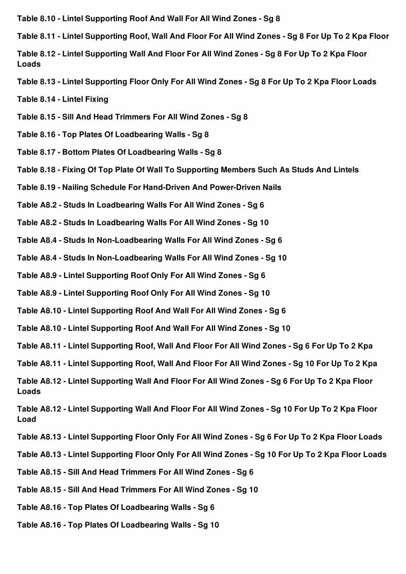
Table 8.10 - Lintel Supporting Roof And Wall For All Wind Zones - Sg 8
Table 8.11 - Lintel Supporting Roof, Wall And Floor For All Wind Zones - Sg 8 For Up To 2 Kpa Floor
Table 8.12 - Lintel Supporting Wall And Floor For All Wind Zones - Sg 8 For Up To 2 Kpa FloorLoads
Table 8.13 - Lintel Supporting Floor Only For All Wind Zones - Sg 8 For Up To 2 Kpa Floor Loads
Table 8.14 - Lintel Fixing
Table 8.15 - Sill And Head Trimmers For All Wind Zones - Sg 8
Table 8.16 - Top Plates Of Loadbearing Walls - Sg 8
Table 8.17 - Bottom Plates Of Loadbearing Walls - Sg 8
Table 8.18 - Fixing Of Top Plate Of Wall To Supporting Members Such As Studs And Lintels
Table 8.19 - Nailing Schedule For Hand-Driven And Power-Driven Nails
Table A8.2 - Studs In Loadbearing Walls For All Wind Zones - Sg 6
Table A8.2 - Studs In Loadbearing Walls For All Wind Zones - Sg 10
Table A8.4 - Studs In Non-Loadbearing Walls For All Wind Zones - Sg 6
Table A8.4 - Studs In Non-Loadbearing Walls For All Wind Zones - Sg 10
Table A8.9 - Lintel Supporting Roof Only For All Wind Zones - Sg 6
Table A8.9 - Lintel Supporting Roof Only For All Wind Zones - Sg 10
Table A8.10 - Lintel Supporting Roof And Wall For All Wind Zones - Sg 6
Table A8.10 - Lintel Supporting Roof And Wall For All Wind Zones - Sg 10
Table A8.11 - Lintel Supporting Roof, Wall And Floor For All Wind Zones - Sg 6 For Up To 2 Kpa
Table A8.11 - Lintel Supporting Roof, Wall And Floor For All Wind Zones - Sg 10 For Up To 2 Kpa
Table A8.12 - Lintel Supporting Wall And Floor For All Wind Zones - Sg 6 For Up To 2 Kpa FloorLoads
Table A8.12 - Lintel Supporting Wall And Floor For All Wind Zones - Sg 10 For Up To 2 Kpa FloorLoad
Table A8.13 - Lintel Supporting Floor Only For All Wind Zones - Sg 6 For Up To 2 Kpa Floor Loads
Table A8.13 - Lintel Supporting Floor Only For All Wind Zones - Sg 10 For Up To 2 Kpa Floor Loads
Table A8.15 - Sill And Head Trimmers For All Wind Zones - Sg 6
Table A8.15 - Sill And Head Trimmers For All Wind Zones - Sg 10
Table A8.16 - Top Plates Of Loadbearing Walls - Sg 6
Table A8.16 - Top Plates Of Loadbearing Walls - Sg 10
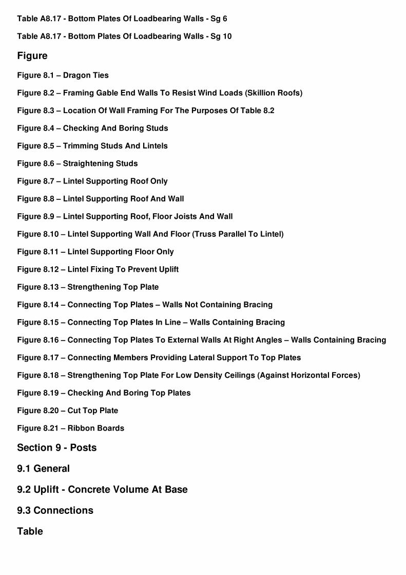
Table A8.17 - Bottom Plates Of Loadbearing Walls - Sg 6
Table A8.17 - Bottom Plates Of Loadbearing Walls - Sg 10
Figure
Figure 8.1 – Dragon Ties
Figure 8.2 – Framing Gable End Walls To Resist Wind Loads (Skillion Roofs)
Figure 8.3 – Location Of Wall Framing For The Purposes Of Table 8.2
Figure 8.4 – Checking And Boring Studs
Figure 8.5 – Trimming Studs And Lintels
Figure 8.6 – Straightening Studs
Figure 8.7 – Lintel Supporting Roof Only
Figure 8.8 – Lintel Supporting Roof And Wall
Figure 8.9 – Lintel Supporting Roof, Floor Joists And Wall
Figure 8.10 – Lintel Supporting Wall And Floor (Truss Parallel To Lintel)
Figure 8.11 – Lintel Supporting Floor Only
Figure 8.12 – Lintel Fixing To Prevent Uplift
Figure 8.13 – Strengthening Top Plate
Figure 8.14 – Connecting Top Plates – Walls Not Containing Bracing
Figure 8.15 – Connecting Top Plates In Line – Walls Containing Bracing
Figure 8.16 – Connecting Top Plates To External Walls At Right Angles – Walls Containing Bracing
Figure 8.17 – Connecting Members Providing Lateral Support To Top Plates
Figure 8.18 – Strengthening Top Plate For Low Density Ceilings (Against Horizontal Forces)
Figure 8.19 – Checking And Boring Top Plates
Figure 8.20 – Cut Top Plate
Figure 8.21 – Ribbon Boards
Section 9 - Posts
9.1 General
9.2 Uplift - Concrete Volume At Base
9.3 Connections
Table
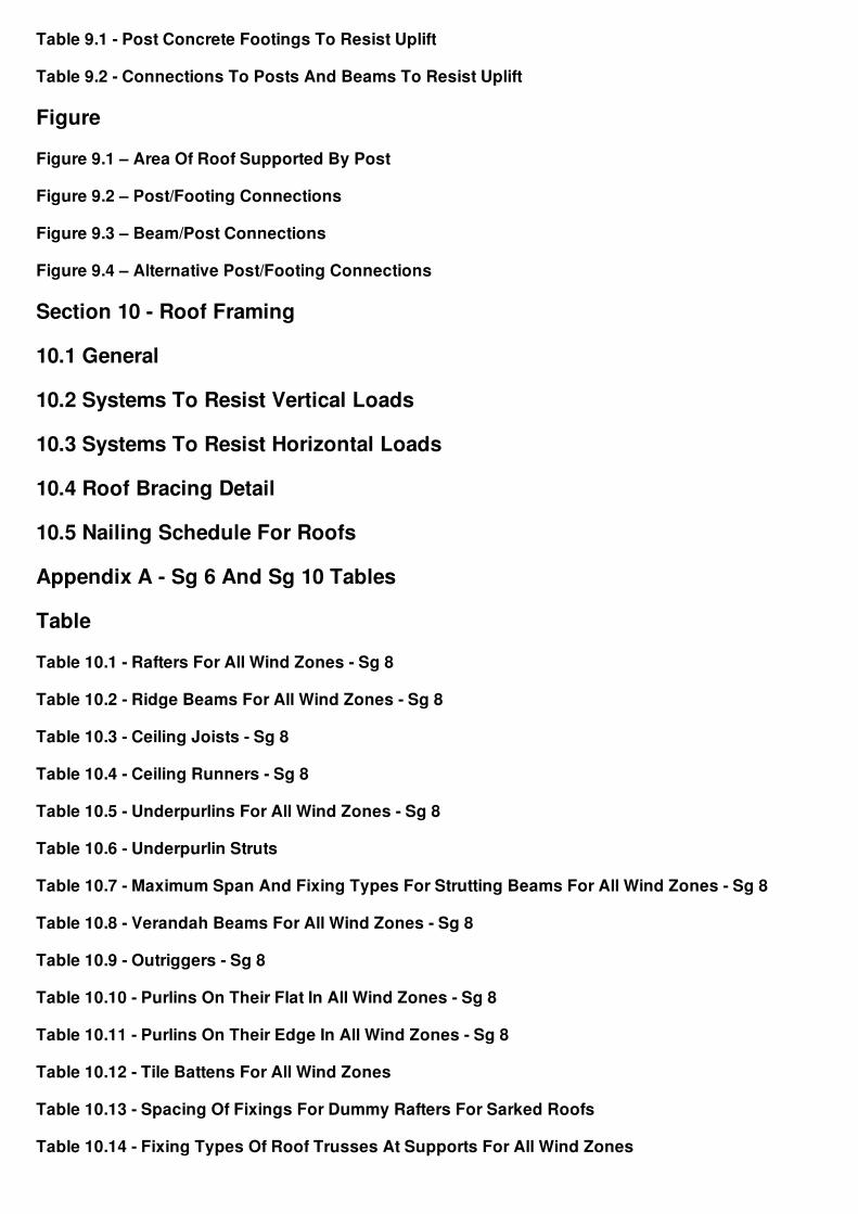
Table 9.1 - Post Concrete Footings To Resist Uplift
Table 9.2 - Connections To Posts And Beams To Resist Uplift
Figure
Figure 9.1 – Area Of Roof Supported By Post
Figure 9.2 – Post/Footing Connections
Figure 9.3 – Beam/Post Connections
Figure 9.4 – Alternative Post/Footing Connections
Section 10 - Roof Framing
10.1 General
10.2 Systems To Resist Vertical Loads
10.3 Systems To Resist Horizontal Loads
10.4 Roof Bracing Detail
10.5 Nailing Schedule For Roofs
Appendix A - Sg 6 And Sg 10 Tables
Table
Table 10.1 - Rafters For All Wind Zones - Sg 8
Table 10.2 - Ridge Beams For All Wind Zones - Sg 8
Table 10.3 - Ceiling Joists - Sg 8
Table 10.4 - Ceiling Runners - Sg 8
Table 10.5 - Underpurlins For All Wind Zones - Sg 8
Table 10.6 - Underpurlin Struts
Table 10.7 - Maximum Span And Fixing Types For Strutting Beams For All Wind Zones - Sg 8
Table 10.8 - Verandah Beams For All Wind Zones - Sg 8
Table 10.9 - Outriggers - Sg 8
Table 10.10 - Purlins On Their Flat In All Wind Zones - Sg 8
Table 10.11 - Purlins On Their Edge In All Wind Zones - Sg 8
Table 10.12 - Tile Battens For All Wind Zones
Table 10.13 - Spacing Of Fixings For Dummy Rafters For Sarked Roofs
Table 10.14 - Fixing Types Of Roof Trusses At Supports For All Wind Zones
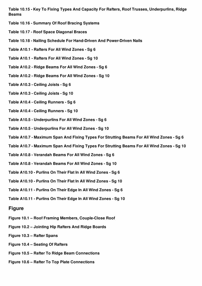
Table 10.15 - Key To Fixing Types And Capacity For Rafters, Roof Trusses, Underpurlins, RidgeBeams
Table 10.16 - Summary Of Roof Bracing Systems
Table 10.17 - Roof Space Diagonal Braces
Table 10.18 - Nailing Schedule For Hand-Driven And Power-Driven Nails
Table A10.1 - Rafters For All Wind Zones - Sg 6
Table A10.1 - Rafters For All Wind Zones - Sg 10
Table A10.2 - Ridge Beams For All Wind Zones - Sg 6
Table A10.2 - Ridge Beams For All Wind Zones - Sg 10
Table A10.3 - Ceiling Joists - Sg 6
Table A10.3 - Ceiling Joists - Sg 10
Table A10.4 - Ceiling Runners - Sg 6
Table A10.4 - Ceiling Runners - Sg 10
Table A10.5 - Underpurlins For All Wind Zones - Sg 6
Table A10.5 - Underpurlins For All Wind Zones - Sg 10
Table A10.7 - Maximum Span And Fixing Types For Strutting Beams For All Wind Zones - Sg 6
Table A10.7 - Maximum Span And Fixing Types For Strutting Beams For All Wind Zones - Sg 10
Table A10.8 - Verandah Beams For All Wind Zones - Sg 6
Table A10.8 - Verandah Beams For All Wind Zones - Sg 10
Table A10.10 - Purlins On Their Flat In All Wind Zones - Sg 6
Table A10.10 - Purlins On Their Flat In All Wind Zones - Sg 10
Table A10.11 - Purlins On Their Edge In All Wind Zones - Sg 6
Table A10.11 - Purlins On Their Edge In All Wind Zones - Sg 10
Figure
Figure 10.1 – Roof Framing Members, Couple-Close Roof
Figure 10.2 – Jointing Hip Rafters And Ridge Boards
Figure 10.3 – Rafter Spans
Figure 10.4 – Seating Of Rafters
Figure 10.5 – Rafter To Ridge Beam Connections
Figure 10.6 – Rafter To Top Plate Connections
Figure 10.7 – Fixing Rafters – Skillion Roof
Figure 10.8 – Example Of Fixing Ridge Beam To Wall
Figure 10.9 – Joints In Ceiling Joists
Figure 10.10 – Ceiling Runners
Figure 10.11 – Underpurlin Struts – Single
Figure 10.12 – Underpurlin Struts – Paired
Figure 10.13 – Strutting Beams
Figure 10.14 – Collar Ties And Underpurlins – Roof Pitches Greater Than 10o
Figure 10.15 – Fixing Cleats
Figure 10.16 – Gable Verge Framing
Figure 10.16(A) – Fly Rafter/Outrigger Orientation
Figure 10.17 – Solid Blocking For Purlins
Figure 10.18 – Purlins Fixed Directly To Rafters
Figure 10.19 – Fixing Purlins And Dummy Rafters To Skillion Roofs
Figure 10.20 – Fixing Purlins And Dummy Rafters To Sarked Roofs
Figure 10.21 – Truss/Top Plate Connections
Figure 10.22 – Roof Plane Diagonal Brace – Timber
Figure 10.23 – Roof Space Diagonal Brace – Alternative Fixings
Figure 10.24 – Sheet Sarked Roof
Section 11 - Building Envelope - Roof And Wall Claddings
11.1 Weathertightness
Section 12 - Interior Linings
12.1 General
Section 13 - Ceilings
13.1 Ceiling Linings
13.2 Ceiling Lining Supports
13.3 Openings In Ceilings
13.4 Water Tanks In The Roof Space
13.5 Structural Ceiling Diaphragms
13.6 Nailing Schedule For Ceilings
Table
Table 13.1 - Ceiling Battens
Table 13.2 - Thickness Of Trimmers And Trimming Joists
Table 13.3 - Nailing Schedule For Hand-Driven And Power-Driven Nails
Figure
Figure 13.1 – Ceiling Lining Supports
Figure 13.2 – Openings In Ceilings
Figure 13.3 – Support Of Water Tanks In The Roof Space
Figure 13.3(A) – Ceiling Diaphragm Protrusions And Cut-Outs
Figure 13.4 – Ceiling Diaphragms
Section 14 - Requirements For 3 Kpa Floor Loads
14.1 General
14.2 Concrete Slab-On-Ground
Appendix A - Sg 6 And Sg 10 Tables
Table
Table 14.1 - Bracing Demand For Various Cladding Combinations For Single-Storey Buildings OnSubfloo
Table 14.2 - Bracing Demand For Various Cladding Combinations For Two-Storey Buildings OnSubfloor F
Table 14.3 - Bracing Demand For Various Cladding Combinations For Single-Storey And ### Two-Storey Build
Table 14.4 - Bearers, 3 Kpa Floor Loads - Sg 8
Table 14.5 - Subfloor Jack Studs, 3 Kpa Floor Loads - Sg 8
Table 14.6 - Square Pile Footings For 3 Kpa Floor Loads
Table 14.7 - Spacing Of M12 Bolts Supporting Stringers For 3 Kpa Floor Loads
Table 14.8 - Floor Joists For 3 Kpa Floor Loads - Sg 8
Table 14.9 - Strip Flooring For 3 Kpa Floor Loads
Table 14.10 - Studs In Loadbearing Walls For All Wind Zones For 3 Kpa Floor Loads - Sg 8
Table 14.11 - Reference Table For Lintel Load Cases
Table 14.12 - Lintel Supporting Roof, Wall And Floor For 3 Kpa Floor Loads - Sg 8
Table 14.13 - Lintel Supporting Wall And Floor Only For 3 Kpa Floor Loads - Sg 8
Table 14.14 - Lintel Supporting Floor Only For 3 Kpa Floor Loads - Sg 8
Table 14.15 - Top And Bottom Plates For Loadbearing Walls, 3 Kpa Floor Loads - Sg 8
Table 14.16 - Structural Plywood Flooring
Table A14.4 - Bearers, 3 Kpa Floor Loads - Sg 6
Table A14.4 - Bearers, 3 Kpa Floor Loads - Sg 10
Table A14.5 - Subfloor Jack Studs, 3 Kpa Floor Loads - Sg 6
Table A14.5 - Subfloor Jack Studs, 3 Kpa Floor Loads - Sg 10
Table A14.8 - Floor Joists For 3 Kpa Floor Loads - Sg 6
Table A14.8 - Floor Joists For 3 Kpa Floor Loads - Sg 10
Table A14.10 - Studs In Loadbearing Walls For All Wind Zones For 3 Kpa Floor Loads - Sg 6
Table A14.10 - Studs In Loadbearing Walls For All Wind Zones For 3 Kpa Floor Loads - Sg 10
Table A14.12 - Lintels Supporting Roof, Wall And Floor For 3 Kpa Floor Loads - Sg 6
Table A14.12 - Lintels Supporting Roof, Wall And Floor For 3 Kpa Floor Loads - Sg 10
Table A14.13 - Lintels Supporting Wall And Floor Only For 3 Kpa Floor Loads - Sg 6
Table A14.13 - Lintels Supporting Wall And Floor Only For 3 Kpa Floor Loads - Sg 10
Table A14.14 - Lintels Supporting Floor Only For 3 Kpa Floor Loads - Sg 6
Table A14.14 - Lintels Supporting Floor Only For 3 Kpa Floor Loads - Sg 10
Table A14.15 - Top And Bottom Plates For Loadbearing Walls, 3 Kpa Floor Loads - Sg 6
Table A14.15 - Top And Bottom Plates For Loadbearing Walls, 3 Kpa Floor Loads - Sg 10
Section 15 - 1.5 Kpa And 2.0 Kpa Snow Loading
15.1 General
15.2 Snow Loading
15.3 Roof Abutting An Upper Wall
Appendix A - Sg 6 And Sg 10 Tables
Table
Table 15.1 - Reference Table For Lintel Load Cases
Table 15.2 - Lintel Supporting Roof Only For All Wind Zones Up To 1.5 Kpa Snow Load - Sg 8
Table 15.3 - Lintel Supporting Roof And Wall For All Wind Zones Up To 1.5 Kpa Snow Load - Sg 8
Table 15.4 - Lintel Supporting Roof, Floor And Wall For All Wind Zones Up To 1.5 Kpa Snow Load -Sg
Table 15.5 - Lintel Supporting Roof, Floor And Wall In All Wind Zones For 3 Kpa Floor Load And UpTo
Table 15.6 - Rafters For All Wind Zones Up To 1.5 Kpa Snow Load - Sg 8
Table 15.7 - Ridge Beams For All Wind Zones Up To 1.5 Kpa Snow Load - Sg 8
Table 15.8 - Verandah Beams For All Wind Zones Up To 1.5 Kpa Snow Load - Sg 8
Table 15.9 - Purlins On Their Flat In All Wind Zones Up To 1.5 Kpa Snow Load - Sg 8
Table 15.10 - Purlins On Their Edge For All Wind Zones Up To 1.5 Kpa Snow Load - Sg 8
Table A15.2 - Lintel Supporting Roof Only For All Wind Zones Up To 1.5 Kpa Snow Load - Sg 6
Table A15.2 - Lintel Supporting Roof Only For All Wind Zones Up To 1.5 Kpa Snow Load - Sg 10
Table A15.3 - Lintel Supporting Roof And Wall For All Wind Zones Up To 1.5 Kpa Snow Load - Sg 6
Table A15.3 - Lintel Supporting Roof And Wall For All Wind Zones Up To 1.5 Kpa Snow Load - Sg10
Table A15.4 - Lintel Supporting Roof, Floor And Wall For All Wind Zones Up To 1.5 Kpa Snow Load- Sg
Table A15.4 - Lintel Supporting Roof, Floor And Wall For All Wind Zones Up To 1.5 Kpa Snow Load- Sg
Table A15.5 – Lintel Supporting Roof, Floor And Wall In All Wind Zones For 3 Kpa Floor Load AndUp
Table A15.5 – Lintel Supporting Roof, Floor And Wall In All Wind Zones For 3 Kpa Floor Load AndUp T
Table A15.6 - Rafters For All Wind Zones Up To 1.5 Kpa Snow Load - Sg 6
Table A15.6 - Rafters For All Wind Zones Up To 1.5 Kpa Snow Load - Sg 10
Table A15.7 - Ridge Beams For All Wind Zones Up To 1.5 Kpa Snow Load - Sg 6
Table A15.7 - Ridge Beams For All Wind Zones Up To 1.5 Kpa Snow Load - Sg 10
Table A15.8 - Verandah Beams For All Wind Zones Up To 1.5 Kpa Snow Load - Sg 6
Table A15.8 - Verandah Beams For All Wind Zones Up To 1.5 Kpa Snow Load - Sg 10
Table A15.9 - Purlins On Their Flat In All Wind Zones Up To 1.5 Kpa Snow Load - Sg 6
Table A15.9 - Purlins On Their Flat In All Wind Zones Up To 1.5 Kpa Snow Load - Sg 10
Table A15.10 - Purlins On Their Edge For All Wind Zones Up To 1.5 Kpa Snow Load - Sg 6
Table A15.10 - Purlins On Their Edge For All Wind Zones Up To 1.5 Kpa Snow Load - Sg 10
Figure
Figure 15.1 – Snow Zones
Figure 15.2 – Roof Abutting Upper Wall
Section 16 - Composite Construction Lintel Tables
16.1 Plywood Box Beam Lintels
16.2 Glue-Laminated Timber Lintels
Table
Table 16.1 - Plywood Box Beam Lintels Supporting Roof Only
Table 16.2 - Glue-Laminated Timber Lintel Equivalents To Plywood Box Beam Lintels In ### Table16.1
Figure
Figure 16.1 – Built-Up Plywood Box Beam Lintel – Vertical Section
Figure 16.2 – Built-Up Plywood Box Beam Lintel – Elevation And Longitudinal Section
Section 17 - Expansive Soils
17.1 General
17.2 Building Sites
17.3 Foundations
17.4 Reinforcement
Print Save EmailFeedback
Contact usPrivacy policyDisclaimerCopyright
Feedback