Embed Size (px)
Citation preview

NZ 2000 T2DL / T2Y2DL

ii
Table of contents:
1. Introduction ......................................................................................................................1 2. Required add-ins ..............................................................................................................1
2.1. How to load an add-in ESPRIT ................................................................................1
2.2. AutoSubStock (optional) ..........................................................................................3 2.3. Turning Work Coordinates .......................................................................................6
3. How to turn on Custom Pages / Custom Settings utility .............................................10
4. Machine setup.................................................................................................................11 4.1. Introduction .............................................................................................................11 4.2. Set the program name, program number ...............................................................12
4.3. Define the turning stock ..........................................................................................13 4.4. Machine parameters ................................................................................................13
4.4.1. Introduction ......................................................................................................13
4.4.2. Machine Setup Utility .....................................................................................13 4.4.3. Output of Program End (M02), Program End and Rewind (M30) or Sub-
Program End (M99) .......................................................................................................14
4.4.4. Work unloader on spindle 2 side: hand or receiver .......................................15 4.4.5. Tool station for part transfer and work unloader ...........................................16 4.4.6. C-axis brake clamp/unclamp...........................................................................17
4.4.7. C-axis roll over ................................................................................................18 4.4.8. Set position of optional stop code (M01) in the NC code .............................21 4.4.9. Output of the end of bar macro call (/2 M98 Pxxxx) ....................................22
4.4.10. 99, 133 or 200 Tool wear offset number (Option).....................................23 4.4.11. Set position of sequence numbers (N) ........................................................24 4.4.12. Sending turrets home with G53 ..................................................................25
5. Tools (T function) ..........................................................................................................25 5.1. T function specifications .........................................................................................25
5.1.1. Introduction ......................................................................................................25
5.1.2. Specify the tool number: Method 1 ................................................................26 5.1.3. Specify the tool number: Method 2 ................................................................28 5.1.4. Restrictions.......................................................................................................30
5.1.5. Tool life management ......................................................................................31 5.1.6. Second home position .....................................................................................35
5.2. SolidTurn Grooving: Control Edge Shift ..............................................................40
5.3. Restrictions of 99, 133 or 200 Tool wear offset number (Option).......................45 6. Spindle direction, speed (S function) and feedrate (F function) .................................46
6.1. Turning spindle direction and milling tool spindle direction ...............................46
6.2. Spindle speed output for CSS unit .........................................................................48 6.3. Feedrate for 4-axis milling operations ...................................................................49 6.4. Output of rapid positioning moves (G00) with linear interpolation moves (G01
F) ..................................................................................................................................50 7. How to output coolant codes .........................................................................................52
7.1. Introduction .............................................................................................................52
7.2. Set the first coolant code .........................................................................................53 7.3. Set the second coolant code (optional) ..................................................................54
iii
7.4. Set a special coolant code (optional)......................................................................58 7.5. Sample NC code ......................................................................................................59
8. Operation synchronization .............................................................................................59 9. Park cycle .......................................................................................................................60
9.1. Introduction .............................................................................................................60
9.2. Park a tool at specific programmed location .........................................................60 9.3. Park the turret home (G28 or G30) ........................................................................61 9.4. Park a turret to its maximal travel position (G53).................................................61
9.5. Park a turret prior to a transfer ...............................................................................63 9.6. Other functionalities ................................................................................................65
10. How to program finished part catching and part transfer .........................................67
10.1. Introduction..........................................................................................................67 10.2. Finished part catching .........................................................................................67
10.2.1. Catching finished part on spindle 1 side after cut-off ...............................67
10.2.2. Catching finished part on spindle 1 side after cut-off with stock
repositioning (programmed first) ..................................................................................69 10.2.3. Catching finished part on spindle 1 side after cut-off with stock
repositioning (programmed last) ...................................................................................73 10.2.4. Manually catching finished part on spindle 1 side ....................................78 10.2.5. Catching finished part on spindle 2 side ....................................................80
10.3. Part transfer ..........................................................................................................84 10.3.1. Part transfer from spindle 1 to spindle 2 with cut-off ...............................84 10.3.2. Part transfer from spindle 1 to spindle 2 with cut-off (when machine
equipped with a barfeeder) ............................................................................................91 10.3.3. Part transfer from spindle 1 to spindle 2 with cut-off and stock
repositioning (programmed last) ...................................................................................99
10.3.4. Part transfer from spindle 1 to spindle 2 without cut-off ....................... 107 10.3.5. Part transfer from spindle 2 to spindle 1 without cut-off ....................... 113 10.3.6. Stock repositioning ................................................................................... 119
10.3.7. Machining of long parts with spindle 1 and 2 synchronized ................. 124 10.3.8. Workpiece Pushing Check (G38) ............................................................ 128 10.3.9. Park turret for transfer .............................................................................. 130
11. Multiple repetitive cycles ........................................................................................ 130 11.1. Introduction....................................................................................................... 130 11.2. Roughing cycle ................................................................................................. 132
11.2.1. Introduction ............................................................................................... 132 11.2.2. O.D./I.D. roughing .................................................................................... 137 11.2.3. Face roughing............................................................................................ 139
11.3. Grooving cycle ................................................................................................. 141 11.3.1. Introduction ............................................................................................... 141 11.3.2. Face grooving............................................................................................ 143
11.3.3. O.D./I.D. grooving .................................................................................... 144 11.4. Threading cycle ................................................................................................ 146
11.4.1. Introduction ............................................................................................... 146
11.4.2. Threading with canned cycle set to single path ...................................... 148 11.4.3. Threading with canned cycle set to off ................................................... 151

iv
11.4.4. Threading with canned cycle set to multiple path .................................. 154 12. Hole machining canned cycles and other functionalities for drilling cycles........ 158
12.1. Introduction....................................................................................................... 158 12.2. Face and side high-speed deep hole drilling / Face and side deep hole drilling
/ Deep hole drilling with G74 ......................................................................................... 163
12.2.1. Face and side high-speed deep hole drilling (G83.5/G87.5).................. 163 12.2.2. Face and side deep hole drilling (G83.6/G87.6) ..................................... 164 12.2.3. Deep hole drilling with G74..................................................................... 165
12.3. Face and side spot drilling (G83/G87) ............................................................ 167 12.4. Face and side tapping / Tapping at center of spindle ..................................... 168
12.4.1. Face and side tapping (G84/G88) ............................................................ 168
12.4.2. Tapping at center of spindle (G32) .......................................................... 169 12.5. Face and side synchronized tapping / Face and side (high-speed) deep hole
synchronized tapping / Spindle synchronized tapping .................................................. 171
12.5.1. Restriction of synchronized tapping ........................................................ 171 12.5.2. Face and side synchronized tapping (M329 G84/M329 G88) ............... 171 12.5.3. Face and side (high-speed) deep hole synchronized tapping (M329
G84/M329 G88) .......................................................................................................... 173 12.5.4. Spindle synchronized tapping (M329 G84) (Option) ............................. 176
12.6. Face and side boring / Boring in turning mode .............................................. 178
12.6.1. Face and side boring (G85/G89) .............................................................. 178 12.6.2. Boring in turning mode ............................................................................ 179
12.7. Spindle / Rotary Tool Spindle Simultaneous Operation Mode ..................... 180
13. 3D coordinate conversion (G68.1) (Option) .......................................................... 184 13.1. Introduction....................................................................................................... 184 13.2. How to output 3D coordinate conversion ....................................................... 184
14. 4-axis wrap milling cycles with interpolation ........................................................ 188 14.1. Introduction....................................................................................................... 188 14.2. Cylindrical interpolation .................................................................................. 188
14.3. Polar coordinate interpolation (Notching) ...................................................... 190 15. Custom Settings index ............................................................................................. 193
15.1. On operation pages ........................................................................................... 193
15.2. On tool pages .................................................................................................... 193 15.3. In machine setup ............................................................................................... 194

1
1. Introduction These notes are about the following post processors:
NZ-T2Y2DL_T1.asc: Upper left turret, machines on spindle 1 side
NZ-T2Y2DL_T2.asc: Upper right turret, machines on spindle 2 (sub spindle) side
This manual documents post processor version of 10/28/2011.
Note: NZ T2DL has no Y-axis; on T2Y2DL both turrets have a Y-axis.
The output will match your machine configuration based on the loaded NZ Machine
Setup in ESPRIT. For example, if you work on a NZ T2DL, no Y-axis movements will
be output in the code. In the following manual, you can ignore any reference to the Y-
axis if your machine is not equipped with this axis.
Post processors require ESPRIT 2011 (Build B18.0.2.0874 or above).
Please refer to NZ programming manual for detailed information on the related G and M-
codes.
The mention (Option) refers to a nonstandard functionality. Please contact your Mori
Seiki reseller for more details.
2. Required add-ins
2.1. How to load an add-in ESPRIT
To load an add-in in ESPRIT, from the Tools menu, select Add-In...:

2
You will then see the add-in window:
To load an add-in, highlight it in the Available Add-Ins list and check in Load Behavior
the box Loaded/Unloaded.
Also check the box Load on Startup: the add-in will then be automatically loaded when
you will start ESPRIT.

3
For the Mori Seiki NZ series, you will need to load the following add-ins:
AutoSubStock (optional)
Turning Work Coordinates
Note that the MoriSeiki AddIn should also be loaded. Some of its utilities can be used to
simplify programming in ESPRIT.
2.2. AutoSubStock (optional)
The AutoSubStock add-in needs to be turned on prior to open a file. This add-in will
allow you to correctly simulate the spindle 2 machining. It will also allow the simulation
of production machining, when cutting on the spindle 1 and the spindle 2 at the same
time.
Once you are done programming a part, simply play the entire simulation and once
complete click on Auto Sub Stock. This will save the sub stock in the spindle 2 and stop
the simulation.

4
If you restart the simulation, you will be able to see the cut on the spindle 1 and spindle 2
sides all at the same time.
Important note: In ESPRIT, from the Tools menu, select Options...

5
On the Machining tab, if you check Enable Stock Automation, you will not need to turn
off the AutoSubStock add-in since the Stock Automation will compute the state and
shape of your stock present in both the spindle 1 and spindle 2:

6
2.3. Turning Work Coordinates
The Turning Work Coordinate add-in will sort your operations in the appropriate work
coordinates and also offset the NC code for the spindle 2 operations. It is necessary to run
this add-in in order to generate correct NC code.
From the Create menu, select Turning Work Coordinates.

7
You will then see the Turning Work Coordinates dialog:
MainSpindle and SubSpindle information are directly coming from the Machine Setup.
WC Name: It corresponds to the Work Coordinate name. Operations located on
the spindle 1 side will be moved in the G54 work coordinate and on the spindle 2
side in G55. Please note that the name is just informative and will not affect the
code. WC Numbers will.

8
WC Numbers: The first field will be used in the NC code. 54 will output G54 at
the beginning of an operation on the spindle 1 side, 55 will output G55 at the
beginning of an operation on the spindle 2 side.
Z Offset: It is used to correctly offset the work coordinate on the spindle 2 side.
The value is read from the Part Stock Length field of the Machine Setup (on the
General tab). The spindle 2 work coordinate will be offset by minus this amount
from the spindle 1 work coordinate. That is why the value you enter in the machine
setup is critical. A wrong value will cause a wrong offset and as a conclusion a part
not cut correctly.
Spindle Orientation: This information is coming from the Machine Setup and
is just informative.
On the Options field, Keep Z axis parallel with Tool axis and Reverse Z axis of WC if
spindle Z axis is reversed will have no effect for this machine.
So, you basically do not need to change anything on this dialog. Once you click on ok, all
your operations will be sorted for you in G54 (spindle 1 side) and G55 (spindle 2 side).
Note that if you want to output different work coordinate numbers, you can change the
WC number to 56, 57, 58 or 59. This machine can work with work coordinates G54,
G55, G56, G57, G58 or G59.

9
If you did already run the add-in, you can still edit the existing work coordinates and
change the name and number to whatever you need:
On the Features tab, double click on an existing work coordinate. So you will be able to
edit it. You can change on the Work Coordinate dialog the Work Coordinate Name
(informative) and, for the NC code, the Standard Work Coordinate Number.
Please note that you can also create a new work coordinate with the desired number and
then move any operation to it.
Finally, you can set an Autorun Mode. So, you will not need to think about running the
add-in every time you need to output the NC code.
None: No autorun mode selected, you have to manually run the add-in to sort
operations.
Before posting: Every time you will output the NC code, the add-in will be run.
Before simulation: Every time you will start the simulation, the add-in will be
run.
Before posting & simulation: Every time you will output the NC code or you
will start the simulation, the add-in will be run.

10
3. How to turn on Custom Pages / Custom Settings utility
In the following manual, you might need to use the Custom tab of an operation page or of
the machine setup to be able to output specific code related to a special function.
To turn this tab on, in ESPRIT, from the Tools menu, select Options...
On the Machining tab, check the checkbox Custom Page, click on Default... (and Save
current as user defaults) and finally on OK.

11
Now, you will have access to the custom page on which you will be able to set some
flags. They will be detailed in the manual, when needed.
Note that when the MoriSeiki AddIn is loaded, you will be able to use the Custom
Settings utility:
Machine parameters can directly be set on the Machine Parameters tab of the
Machine Setup Utility (see part 4.4.2. Machine Setup Utility)
On operation and tool pages, the function of the required custom settings will be
displayed
4. Machine setup
4.1. Introduction
Some important settings regarding the NC output are set in the Machine Setup.

12
To open the Machine Setup, click on Common Machining and then on Setup:
4.2. Set the program name, program number
To set the program name and number output at the beginning of your NC code on each
channel, you will need to go to the NC Output tab of the Machine Setup. Under General
Properties of the Turret Program Output, enter the name of your program, its number.
You can also specify here the unit of your NC code and the coordinate mode.
Sample NC code: %
O0001(TEST)
(ESPRIT)
(MACHINE NAME: NZ2000-T2Y2DL TURRET1 TEST)
(POST PROCESSOR: E11MSP-NZ-T2Y2DL-2011-09-26-T1 FOR NZ2000-
T2Y2DL)
(9/27/2011 2:29:00 AM)

13
4.3. Define the turning stock
On the General tab of the Machine Setup, you can define your turning stock. For turning
operations, if you are using the Stock Type Automation, your NC output will be linked to
the defined turning stock.
Use Start Position Z to position the stock along the Z axis. It will be used, for example,
to define the front face facing amount.
Use Stock Type to define the shape of your stock: Bar, Tube (Inside Diameter will then
be available) or Casting (Casting Feature will then be available for selection).
Use Bar Diameter to specify the diameter of your stock.
Use Total Bar Length to define the total length of your stock.
Finally use Part Stock Length to define the length of your finish part. This will be used
by the Turning Work Coordinates add-in.
Note: The stock configuration will be detailed when needed in this manual.
4.4. Machine parameters
4.4.1. Introduction
Machine parameters can either be set on the Machine Parameters tab of the Machine
Setup Utility (part of the MoriSeiki AddIn) or manually using the Custom tab of the
Machine Setup. Both methods will be explained below.
4.4.2. Machine Setup Utility
You can set the machine parameters on the Machine Parameters tab of the Machine Setup
Utility.

14
4.4.3. Output of Program End (M02), Program End and Rewind (M30) or Sub-Program End (M99)
On the Custom tab of the Machine Setup, set Custom Setting 1 to 2 to output M02, set it
to 30 to output M30 or set it to 99 to output M99 at the end of the NC code of each turret.
Please note that M30 is the default, so if you omit (or enter a wrong value) to enter the
value in the Custom Setting 1 field, M30 will be output.
Sample NC code with Custom Setting 1 set to 2: M197
M05

15
M46
M201 (CHIP CONVEYOR STOP)
M02
%
Sample NC code with Custom Setting 1 set to 30: M197
M05
M46
M201 (CHIP CONVEYOR STOP)
M30
%
Sample NC code with Custom Setting 1 set to 99: M197
M05
M46
M201 (CHIP CONVEYOR STOP)
M99
%
4.4.4. Work unloader on spindle 2 side: hand or receiver
On the Custom tab of the Machine Setup, set Custom Setting 2 to 1 if your machine is
equipped with a receiver; set it to 0 if it is equipped with an arm.
This will affect the NC output when you program your finished part catching. It will
differ based on the type of work unloader present on your machine.
Please note that machine equipped with an arm is the default, so if you omit (or enter a
wrong value) to enter the value in the Custom Setting 2 field, the code will be output for
an arm equipped machine.
Sample NC code (head 2) of the part release for a machine equipped with an arm: N500 (RELEASE)
M09
G28 U0
G28 V0 W0
G00 T0100
M05

16
G53 Z0.0
G53 B-50.0
M73
M11
G04 U1.0
G330
M74
M52
M51
G04 U3.0
M57
M59
G28 U0
G28 V0 W0
Sample NC code (head 2) of the part release for a machine equipped with a receiver
(workpiece ejector OUT (M47)): N500 (RELEASE)
M09
G28 U0
G28 V0 W0
G00 T0100
M05
G53 Z0.0
M73
G53 B-50.0
M11
G04 U1.0
M47
M51
G04 U3.0
G330
M74
M59
G28 U0
G28 V0 W0
For additional information on how to program finished part catching, see part 10.2.
Finished part catching.
4.4.5. Tool station for part transfer and work unloader
By default, station 1 will be used as empty station during part transfer and work unloader.
It can be changed in the Machine Setup using the Custom Setting 4 for head 1 and
Custom Setting 5 for head 2. You can enter a value between 1 and 16.
For example, if Custom Setting 4 is set to 4 and Custom Setting 5 is set to 7, the tool call
for transfer will be T0400 for head 1 and T0700 for head 2.

17
Note: If the station number specified is out of range (value entered greater than 16 or less
than 0), you will get the following error message in your NC code: ERROR: WRONG
TRANSFER STATION NUMBER ENTERED IN MACHINE SETUP.
For additional information on finished part catching and part transfer, see part 10. How to
program finished part catching and part transfer.
4.4.6. C-axis brake clamp/unclamp
By default, C-axis brake clamp (M68) and unclamp (M69) M-codes will be output in the
NC code.
If you do not want to output these M-codes in the NC code, set in the Machine Setup
Custom Setting 7 to 1. If you omit (or enter a wrong value) to enter the value in the
Custom Setting 7 field, C-axis brake clamp/unclamp M-codes will be output in the NC
code.
Sample NC code with Custom Setting 7 set to 0: N5 (SPINDLE-2 DRILLING XYZ FACE)
18
(T0404 SPOT 03.15 UPPER RIGHT)
G28 U0
G28 V0 W0
G55
G00 T0404
M69
G98 G17 M45
G28 H0
G97 S3000 M13
G00 C90.0
M68
G00 Z-1.0
X0.0 Y-20.651 M08
G83 Z9.976 R7.426 F150.0
X41.301 Y0.0
X0.0 Y20.651
X-41.301 Y0.0
G80
M09
G28 U0
G28 V0 W0
M05
M69
M46
Sample NC code with Custom Setting 7 set to 1: N5 (SPINDLE-2 DRILLING XYZ FACE)
(T0404 SPOT 03.15 UPPER RIGHT)
G28 U0
G28 V0 W0
G55
G00 T0404
G98 G17 M45
G28 H0
G97 S3000 M13
G00 C90.0
G00 Z-1.0
X0.0 Y-20.651 M08
G83 Z9.976 R7.426 F150.0
X41.301 Y0.0
X0.0 Y20.651
X-41.301 Y0.0
G80
M09
G28 U0
G28 V0 W0
M05
M46
4.4.7. C-axis roll over
On the Custom tab of the Machine Setup, set Custom Setting 9 to 1 to turn on C-axis roll
over.
Note that you will need to turn it on on the machine control as well.

19
On machine control, if <Roll over for C-axis> is invalid
(NC Parameter 1008 bit 0 = 0):
min. C-axis value is -99999.999°
max. C-axis value is +99999.999°
In ESPRIT, Custom Setting 9 in Machine Setup is set to 0.
On machine control if <Roll over for C-axis> is valid
(NC Parameter 1008 bit 0 = 1):
min. C-axis value is -359.999°
max. C-axis value is 359.999°
In ESPRIT, Custom Setting 9 in Machine Setup is set to 1.
When C-axis roll over is on, C-axis will be indexed between -360° and 360°.
Sample NC code of an operation with C-axis roll over off: N5 (SPINDLE-1 MILLING)
(T1212 EM 09.0 UPPER LEFT)
G28 U0
G28 V0 W0
G54
G00 T1212
M69
G98 G19 M45
G28 H0
G97 S3000 M13
G00 C365.75
M68
.

20
.
. M09
G28 U0
G28 V0 W0
M05
M69
M46
Sample NC code of an operation with C-axis roll over on: N5 (SPINDLE-1 MILLING)
(T1212 EM 09.0 UPPER LEFT)
G28 U0
G28 V0 W0
G54
G00 T1212
M69
G98 G19 M45
G28 H0
G97 S3000 M13
G00 C5.75 (Index C-axis)
M68
.
.
. M09
G28 U0
G28 V0 W0
M05
M69
M46
Note: During 4-axis milling (wrap and rotary face milling) operations with C-axis roll
over on, if C-axis value exceeds a revolution (value output greater than 360° or less than -
360°), you will get the following error message in your NC code: ERROR: C-AXIS
OVER LIMIT: ROLL-OVER MUST BE TURNED OFF.
Sample NC code (C-axis roll over off): N5 (SPINDLE-1 THREAD WRAP MILLING)
(T0808 EM 09.0 UPPER LEFT)
G28 U0
G28 V0 W0
G54
G00 T0808
M69
G98 G19 M45
G28 H0
G97 S3000 M13
G00 C-0.338
G00 Z-4.488
X150.0 Y0.0 M08
X140.0

21
G01 X106.0 F600.0
Z-104.488 C1439.662 F648.0
X140.0 F600.0
G00 X150.0
M09
G28 U0
G28 V0 W0
M05
M69
M46
Sample NC code (C-axis roll over on): N5 (SPINDLE-1 THREAD WRAP MILLING)
(T0808 EM 09.0 UPPER LEFT)
G28 U0
G28 V0 W0
G54
G00 T0808
M69
G98 G19 M45
G28 H0
G97 S3000 M13
G00 C-0.338
G00 Z-4.488
X150.0 Y0.0 M08
X140.0
G01 X106.0 F600.0
Z-104.488 ERROR: C-AXIS OVER LIMIT: ROLL-OVER MUST BE TURNED OFF
4.4.8. Set position of optional stop code (M01) in the NC code
By default, optional stop codes (M01) will be output on each head after synchronization
codes in the NC code. This way, optional stop can be turned on on the machine while
running the NC code on both heads at the same time (production mode).
Set in the Machine Setup Custom Setting 10 to 1 to output optional stop codes after each
operation and each programmed wait code. If optional stop is turned on on the machine,
this mode can only be used when running NC code on one head at a time (NC code
proofing mode).
Set in the Machine Setup Custom Setting 10 to 2 to output optional stop codes at tool
cancellation and after each programmed wait code. If optional stop is turned on on the
machine, this mode can only be used when running NC code on one head at a time (NC
code proofing mode).
Note that if you omit (or enter a wrong value) to enter the value in the Custom Setting 10
field, optional stop codes will only be output after wait codes in the NC code.

22
4.4.9. Output of the end of bar macro call (/2 M98 Pxxxx)
If your machine is equipped with a barfeeder, you can output in the NC code the end of
bar macro call with /2 M98 Pxxxx (xxxx is the program number). This way, when the bar
(stock) reaches the end, the automatic barfeeder will load a new one.
In the ESPRIT Machine Setup, set Custom String 9 to the program number you desire to
call to check for the end of bar. It will then be output as entered in the NC code.
Note that if you omit (or enter a wrong value) to enter the value in Custom String 9 field,
end of bar macro call will not be output.

23
See part 10.3.6. Stock repositioning for sample NC code.
4.4.10. 99, 133 or 200 Tool wear offset number (Option)
By default, 66 tool wear offset number will be used as a limit when defining your tools in
ESPRIT: the maximum tool wear offset number you will be able to output in the NC code
will be 66.
If your machine has the 99, 133 or 200 tool wear offset number option, set in the
Machine Setup Custom String 10 to 99, 133 or 200. 99, 133 or 200 Tool wear offset
number will be used as a limit when defining your tools in ESPRIT: the maximum tool
wear offset number you will be able to output in the NC code will be 99, 133 or 200.
Tool calls will be done with five digits instead of four when using the 133 or 200 option:
tool wear offset numbers have three digits instead of only two.
Note that if you omit (or enter a wrong value) to enter the value in Custom String 10
field, the default 66 tool wear offset number will be used.

24
Note: See part 5. Tools (T function) for programming details.
4.4.11. Set position of sequence numbers (N)
By default, sequence numbers (N) will be output at the beginning of each operation in the
NC code.
Set in the Machine Setup Custom String 10 to NTCOnly to output sequence numbers at
tool change only.
Note that if you omit (or enter a wrong value) to enter the value in the Custom String 10
field, sequence numbers will be output at the beginning of each operation in the NC code.

25
This setting will only affect regular cutting operations: sequence numbers for transfer
operations will always be output.
Sequence numbers for SolidTurn Roughing operations with canned cycle on will also
always be output. This is to avoid sequence number mismatch since sequence numbers
will be used at the beginning and at the end of profile description.
4.4.12. Sending turrets home with G53
CAUTION !!! MoriSeiki AddIn must be loaded. This function can only be used using
Machine Setup Utility.
On the Machine Parameters tab of the Machine Setup Utility, you can specify the turrets
indexing X and Z positions. They will then be output in the NC code with G53.
Note that if no value is specified in one of the fields for an axis, the turret will be sent
home with G28 (default behavior) along this axis.
5. Tools (T function)
5.1. T function specifications
5.1.1. Introduction
T[][][][];
The first two digits of a T number specify the tool number and the tool geometry offset
number.
The last two digits of a T number specify the tool wear offset number.

26
Note: It is recommended to use the same number for the tool number and tool wear offset
number when specifying a T command in a program to avoid operator's errors.
In ESPRIT, you have two different ways to enter the tool call number that will be output
in the NC code. They will be explained below.
5.1.2. Specify the tool number: Method 1
A tool number in ESPRIT shall be entered as three- (101, for example) or four-digit
numbers (1414, for example). The tool number will be entered in the Tool Number
dialogue box on the respective tool page. It will then be output in the NC code.
If, for example on turret 1, the Tool Number entered is 101, the tool call output will be
T0101. If 1414 is entered, the tool call output will be T1414.
Turning tools:

27
Milling tools:

28
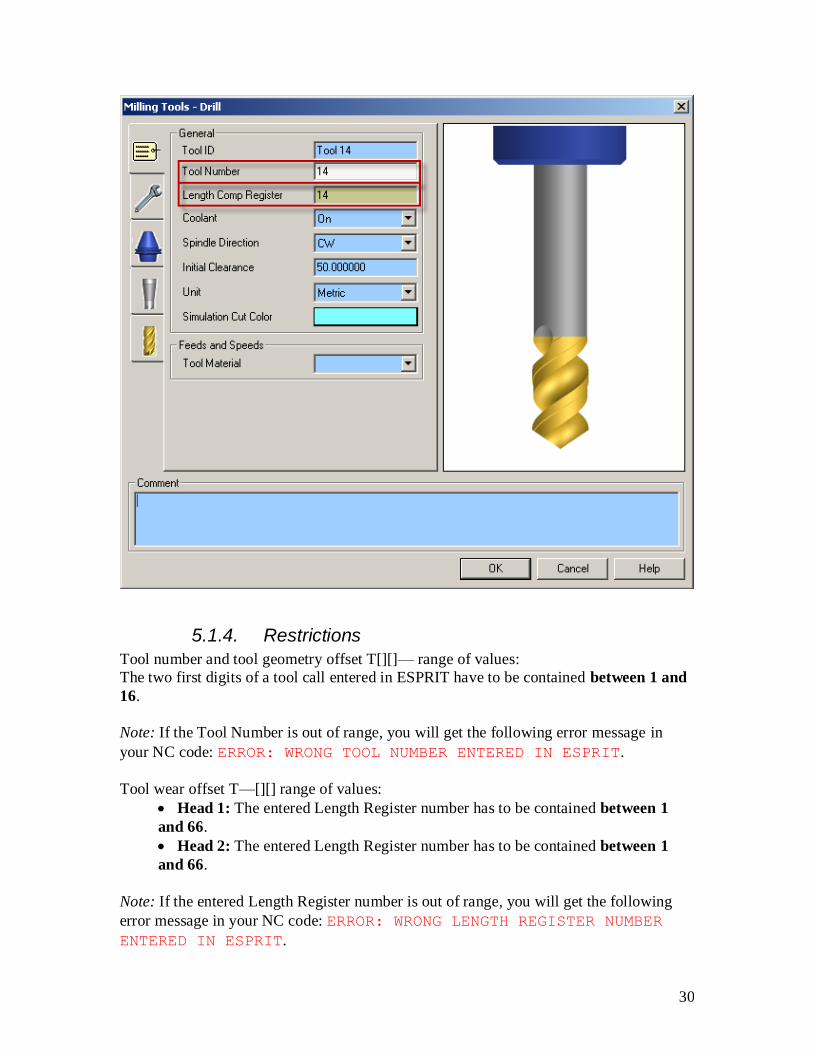
5.1.3. Specify the tool number: Method 2
If the Tool Number is entered as a one-digit number (1, for example) or a two-digit
number (14 for example) in ESPRIT, the post processor will combine this number to the
number entered in the Length Register dialogue box.
If, for example on turret 1, the Tool Number entered is 1 and the Length Register number
entered is 3, the tool call output will be T0103.
Turning tools:

29
Milling tools:
30
5.1.4. Restrictions
Tool number and tool geometry offset T[][]— range of values:
The two first digits of a tool call entered in ESPRIT have to be contained between 1 and
16.
Note: If the Tool Number is out of range, you will get the following error message in
your NC code: ERROR: WRONG TOOL NUMBER ENTERED IN ESPRIT.
Tool wear offset T—[][] range of values:
Head 1: The entered Length Register number has to be contained between 1
and 66.
Head 2: The entered Length Register number has to be contained between 1
and 66.
Note: If the entered Length Register number is out of range, you will get the following
error message in your NC code: ERROR: WRONG LENGTH REGISTER NUMBER
ENTERED IN ESPRIT.

31
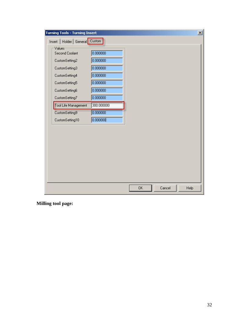
5.1.5. Tool life management
On the Custom tab of the tool page, set Custom Setting 8 to 300 to turn on the tool life
management.
Turning tool page:
With Custom Settings utility (MoriSeiki AddIn loaded):
32
Milling tool page:

33
With Custom Settings utility (MoriSeiki AddIn loaded):

34
This will trigger the output of G336 (group command) and M300 (tool life count): The
tool call will be made with G336 and at tool cancel M300 will be output.
If you omit (or enter a wrong value) to enter the value in the Custom Setting 8 field, the
tools will be called with G00; G336 and M300 will not be output in the NC code.
Sample NC code with tool life management on: N5 (SPINDLE-1 PECK CANNED CYCLE)
(T7 27MM INSERT DRILL UPPER LEFT)
G28 U0
G28 V0 W0
G54
G336 T7
M69
G99 G18 M46
G97 S3000 M03
G00 Y0.0 Z2.0
X0.0 M08
G83.6 Z-28.112 R0.0 Q2000 F0.05
G80
M09

35
M300
G28 U0
G28 V0 W0
M05
Sample NC code with tool life management off: N5 (SPINDLE-1 PECK CANNED CYCLE)
(T0707 27MM INSERT DRILL UPPER LEFT)
G28 U0
G28 V0 W0
G54
G00 T0707
M69
G99 G18 M46
G97 S3000 M03
G00 Y0.0 Z2.0
X0.0 M08
G83.6 Z-28.112 R0.0 Q2000 F0.05
G80
M09
G28 U0
G28 V0 W0
M05
5.1.6. Second home position
On the Custom tab of the tool page, set Custom Setting 3 to 30 to use the second zero
return of the machine (G30) for this tool.
Turning tool page:

36
With Custom Settings utility (MoriSeiki AddIn loaded):

37
Milling tool page:

38
With Custom Settings utility (MoriSeiki AddIn loaded):

39
This will trigger the output of G30 (instead of G28) whenever a turret needs to be sent
home.
If you omit (or enter a wrong value) to enter the value in the Custom Setting 3 field,
turrets will be sent to the machine zero point with G28; G30 will not be output in the NC
code.
Sample NC code with second home position on: N70 (SPINDLE-1 CANNED CYCLE SINGLE PATH)
(T0505 THREADING INSERT ID UPPER LEFT)
G30 U0
G30 V0 W0
G54
G00 T0505
M69
G99 G18 M46
G97 S500 M03
G00 Y0.0 Z3.0
X25.459 M08
Z1.863
M24

40
G76 P010060
G76 X31.75 Z-14.916 P1146 Q400 F2.117
G00 Z3.0
M09
G30 U0
G30 V0 W0
M05
Sample NC code with second home position off: N70 (SPINDLE-1 CANNED CYCLE SINGLE PATH)
(T0505 THREADING INSERT ID UPPER LEFT)
G28 U0
G28 V0 W0
G54
G00 T0505
M69
G99 G18 M46
G97 S500 M03
G00 Y0.0 Z3.0
X25.459 M08
Z1.863
M24
G76 P010060
G76 X31.75 Z-14.916 P1146 Q400 F2.117
G00 Z3.0
M09
G28 U0
G28 V0 W0
M05
5.2. SolidTurn Grooving: Control Edge Shift
When you finish a groove with control edge shift, you can output the NC code controlling
the left corner of the grooving insert for the left side of the groove and its right corner for
the right side of the groove. You can assign to your grooving insert two different tool
wear offset data. One register will be for the left edge of the tool and another will be for
the right edge.

41
To enable Control Edge Shift in ESPRIT, on the Finish tab of the SolidTurn Grooving
operation, set Control Edge Shift to Yes:

42
Notes:
This is only effective for the finish pass of the groove.
The Finish Mode has to be set to Per Side.
The second tool wear offset data can be specified on the General tab of the Grooving
Insert tool page in the Edge Shift Register field:

43
Tool wear offset range of values:
Head 1: The entered Edge Shift Register number has to be contained between 1
and 66.
Head 1 with tool life management on: The entered Edge Shift Register number
has to be contained between 1 and 66.
Head 2: The entered Edge Shift Register number has to be contained between 1
and 66.
Head 2 with tool life management on: The entered Edge Shift Register number
has to be contained between 1 and 66.
Note: If the entered Edge Shift Register number is out of range, you will get the
following error message in your NC code: ERROR: WRONG EDGE SHIFT
REGISTER NUMBER ENTERED IN ESPRIT.
Sample NC code with control edge shift on: N5 (SPINDLE-1 GROOVING)

44
(T0404 GROOVING INSERT OD UPPER LEFT)
G28 U0
G28 V0 W0
G54
G00 T0404
M69
G99 G18 M46
G97 S900 M04
G00 Y0.0 Z-4.213
X34.0 M08
G01 X26.25 F0.15
G00 X34.0
Z-5.267
G01 X26.25
G00 X34.0
Z-6.321
G01 X26.25
G00 X34.0
Z-7.375
G01 X26.25
G00 X30.0
Z-2.5 T0424
G01 X26.0 F0.1
Z-4.206
X28.5
G00 X30.0
Z-7.5 T0404
G01 X26.0
Z-5.794
X28.5
G00 X34.0
Sample NC code with control edge shift and tool life management on: N5 (SPINDLE-1 GROOVING)
(T4 GROOVING INSERT OD UPPER LEFT)
G28 U0
G28 V0 W0
G54
G336 T4
M69
G99 G18 M46
G97 S900 M04
G00 Y0.0 Z-4.213
X34.0 M08
G01 X26.25 F0.15
G00 X34.0
Z-5.267
G01 X26.25
G00 X34.0
Z-6.321
G01 X26.25
G00 X34.0
Z-7.375
G01 X26.25
G00 X30.0
G336 T4 H24

45
Z-2.5
G01 X26.0 F0.1
Z-4.206
X28.5
G00 X30.0
G336 T4
Z-7.5
G01 X26.0
Z-5.794
X28.5
G00 X34.0
5.3. Restrictions of 99, 133 or 200 Tool wear offset
number (Option)
If your machine has the 99, 133 or 200 tool wear offset number option, the following
restrictions apply.
Regular operations - Tool wear offset range of values:
With the 99 option:
Head 1: The entered Length Register number has to be contained between 1
and 99.
Head 2: The entered Length Register number has to be contained between 1
and 99.
With the 133 option:
Head 1: The entered Length Register number has to be contained between 1
and 133.
Head 2: The entered Length Register number has to be contained between 1
and 133.
With the 200 option:
Head 1: The entered Length Register number has to be contained between 1
and 200.
Head 2: The entered Length Register number has to be contained between 1
and 200.
Note: If the entered Length Register number is out of range, you will get the following
error message in your NC code: ERROR: WRONG LENGTH REGISTER NUMBER
ENTERED IN ESPRIT.
With the 133 and 200 option, you now have five digits instead of four output at tool call.
So if you are using method 1 to enter your tool and tool wear offset numbers when
creating your tools in ESPRIT, make sure to enter a five-digit number. For example,
where before you would enter 101 to output in the NC code T0101, you now have to
enter 1001 to output T01001.

46
SolidTurn Grooving with Control Edge Shift - Tool wear offset range of values:
With the 99 option:
Head 1: The entered Edge Shift Register number has to be contained between 1
and 99.
Head 1 with tool life management on: The entered Edge Shift Register number
has to be contained between 1 and 99.
Head 2: The entered Edge Shift Register number has to be contained between 1
and 99.
Head 2 with tool life management on: The entered Edge Shift Register number
has to be contained between 1 and 99.
With the 133 option:
Head 1: The entered Edge Shift Register number has to be contained between 1
and 133.
Head 1 with tool life management on: The entered Edge Shift Register number
has to be contained between 1 and 133.
Head 2: The entered Edge Shift Register number has to be contained between 1
and 133.
Head 2 with tool life management on: The entered Edge Shift Register number
has to be contained between 1 and 133.
With the 200 option:
Head 1: The entered Edge Shift Register number has to be contained between 1
and 200.
Head 1 with tool life management on: The entered Edge Shift Register number
has to be contained between 1 and 200.
Head 2: The entered Edge Shift Register number has to be contained between 1
and 200.
Head 2 with tool life management on: The entered Edge Shift Register number
has to be contained between 1 and 200.
Note: If the entered Edge Shift Register number is out of range, you will get the
following error message in your NC code: ERROR: WRONG EDGE SHIFT
REGISTER NUMBER ENTERED IN ESPRIT.
6. Spindle direction, speed (S function) and feedrate
(F function)
6.1. Turning spindle direction and milling tool spindle
direction
For turning operations using a cutting insert (Roughing, Contouring, Grooving and
Threading), the spindle direction will automatically be computed by the post processors
and will output the correct M-code (M03 or M04) based on the hand of the tool on the

47
holder and the orientation of the tool. The field Spindle Direction on the General tab has
not effect on the output.
For the turning Drilling and milling operations, the turning spindle direction or milling
tool spindle direction is specified by the Spindle Direction pull-down on the first tab of
the tool page.

48
6.2. Spindle speed output for CSS unit
On a turning operation page, if you choose to output the turning spindle speed in the unit
CSS (Constant Surface Speed), a warm up speed will first be output with the G97 code
before the first positioning move. The speed value is computed at the first diameter from
where the CSS command will be turned on. Next, after positioning the tool, the CSS is
turned on by the output of G96 S. The cut is done and finally, at the last diameter, the
CSS is cancelled by the output of G97 S with S computed at the current last diameter.

49
Sample NC code: N5 (SPINDLE-1 CONTOURING FACE)
(T0606 TURNING INSERT OD UPPER LEFT)
G28 U0
G28 V0 W0
G54
G00 T0606
M69
G99 G18 M46
G50 S5000
G97 S770 M03 (Warm up speed)
G00 Y0.0 X62.0
Z0.0 M08
G96 S150 (CSS)
G01 X-0.762 F0.15
Z1.25
G97 S5000 (Cancellation of CSS)
6.3. Feedrate for 4-axis milling operations
For Wrap Pocketing and Wrap Contouring operations with Cylindrical Interpolation set
to No, Rotary Face Pocketing and Rotary Face Contouring operations with Polar
Interpolation set to No or 5-axis operations with 5th
axis locked with Z-axis (5-axis
operation becomes a 4-axis operation), a rotary feedrate will be computed by the post
processor, based on the linear and rotary (C-axis) moves of the cut.
This computation is necessary since two types of feedrate are involved for 4-axis wrap
cuts: linear feedrates (linear moves along XYZ) in mm/min (or inch/min) and rotary
feedrates (angular moves around the C-axis) in deg/min.
In ESPRIT, when programming such operations, simply enter the desired XY and Z PM
(per minute) feedrate values. The post will then, based on these values, compute the
correct 4-axis feedrate.

50
6.4. Output of rapid positioning moves (G00) with linear interpolation moves (G01 F)
CAUTION !!! Works with milling operations
By default, rapid positioning moves will be output with G00 in the NC code.
If you want to output your rapid positioning moves with linear interpolation (G01 F),
enter the desired rapid feedrate value in the Custom Setting 1 field of the Custom tab of
the milling operation page.

51
With Custom Settings utility (MoriSeiki AddIn loaded):
aaaa
Sample NC code (NC code output with G00): N5 (SPINDLE-1 MILLING)
(T0101 EM 20 OD)
G28 U0
G28 V0 W0
G54
G00 T0101
M69
G98 G19 M45
G97 S3000 M13
G00 C0.0
M68
G00 Z32.4
X130.0 Y-50.0 M08
G01 X95.0 F240.0
Y50.0 F300.0
G00 X130.0
G01 X94.5 F240.0
Y50.0 F300.0
G00 X130.0
G01 X94.0 F240.0
Y50.0 F300.0
G00 X130.0
M01

52
Sample NC code (NC code output with G01 F): N5 (SPINDLE-1 MILLING)
(T0101 EM 20 OD)
G28 U0
G28 V0 W0
G54
G00 T0101
M69
G98 G19 M45
G97 S3000 M13
G00 C0.0
M68
G00 Z32.4
X130.0 Y-50.0 M08
G01 X95.0 F240.0
Y50.0 F300.0
X130.0 F450.0
X94.5 F240.0
Y50.0 F300.0
X130.0 F450.0
X94.0 F240.0
Y50.0 F300.0
X130.0 F450.0
M01
7. How to output coolant codes
7.1. Introduction
The Mori Seiki NZ Series can handle multiple different types of coolant:
Code Function
M08 Coolant ON
M09 Coolant OFF
M382 Shower coolant ON
M383 Shower coolant OFF
M478 Through-spindle coolant ON
M479 Through-spindle coolant OFF
M621 Super high pressure coolant ON
M622 Super high pressure coolant OFF
M651 Chuck top coolant ON
M652 Chuck top coolant OFF
The post processor will handle the output of two different coolant codes per tool.

53
7.2. Set the first coolant code
The first coolant code can be selected using the Coolant pull-down menu on the tool
pages.
Turning tool page:
Milling tool page:

54
Set Coolant to:
On to output M08 (M09)
Flood to output M382 (M383)
Flood Through Spindle to output M478 (M479)
On Through Spindle to output M621 (M622)
Mist to output M651 (M652)
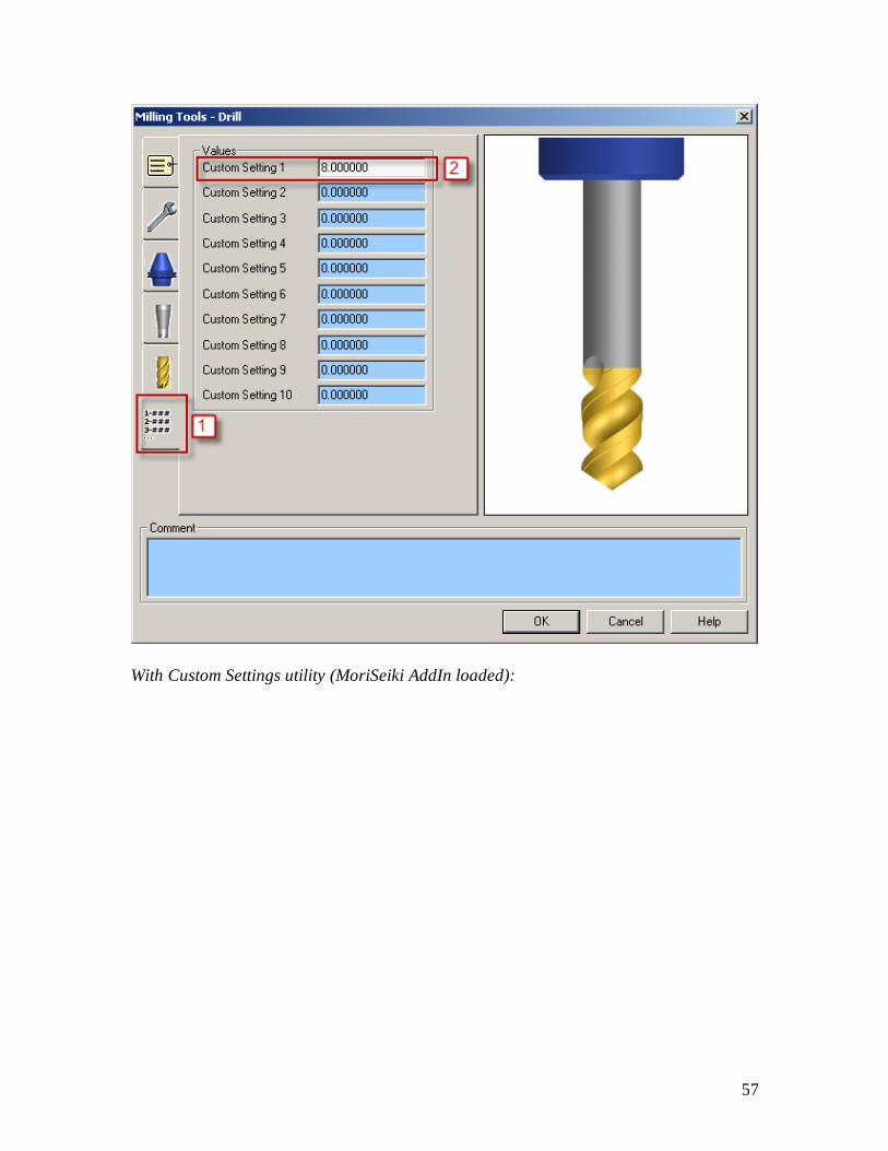
7.3. Set the second coolant code (optional)
If you desire to output a second coolant code (which is optional), enter the coolant code
value in the Custom Setting 1 field of the Custom tab of the tool page.
Turning tool page:

55
With Custom Settings utility (MoriSeiki AddIn loaded):

56
Milling tool page:
57
With Custom Settings utility (MoriSeiki AddIn loaded):

58
Set Custom Setting 1 to:
8 to output M08 (M09)
382 to output M382 (M383)
478 to output M478 (M479)
621 to output M621 (M622)
651 to output M651 (M652)
7.4. Set a special coolant code (optional)
If you desire to output a special coolant code (which is optional, like high pressure
coolant code for example), enter the coolant code ON value in the Custom Setting 6 field
of the Custom tab of the tool page and the coolant code OFF value in the Custom Setting
7 field of the Custom tab of the tool page. Note that both values will need to be entered
for the M-codes to be output in the NC code.
The codes will then be output in NC code: special coolant code ON will be output before
turning spindle or live tool speed output; special coolant code OFF will be output after
turning spindle or live tool stop code (M05).

59
7.5. Sample NC code
Sample NC code with first coolant set to on (M08) and second coolant set to shower
coolant (M382): N5 (SPINDLE-1 PECK CANNED CYCLE)
(T0707 27MM INSERT DRILL UPPER LEFT)
G28 U0
G28 V0 W0
G54
G00 T0707
M69
G99 G18 M46
G97 S3000 M03
G00 Y0 Z2.0
X0.0 M08 (Coolant ON)
M382 (Shower coolant ON)
G83.6 Z-28.112 R0.0 Q2000 F0.05
G80
M09 (Coolant OFF)
M383 (Shower coolant OFF)
8. Operation synchronization Operation synchronization M-codes start at M101 and can incrementally reach M197. In
the NC code, when M197 is reached or exceeded, the next output wait code will be
output in the (101; 197) range: M197 will never be exceeded.
Sample NC code: M194
Z-9.875
X59.0
G00 Z2.0
X57.5
M195
G01 Z-3.0
M196
Z-9.875
X58.0
G00 Z2.0
X56.5
M197
G01 Z-3.0
M101
Z-9.875
X57.0
G00 Z2.0
X55.5
M101
G01 Z-3.0
M102
Z-9.875

60
X56.0
G00 Z2.0
X54.5
M103
G01 Z-3.0
9. Park cycle
9.1. Introduction
With the Park cycle of ESPRIT, you will have different possibilities to park a tool located
on head 1 or 2. It is a great way to park a tool above a spindle to a clearance position, so
you can safely transfer the part from one side to the other. You can also send a tool home
along the X, Y (Y-axis specifications only) and/or Z axis. You finally can park a turret to
its maximal positions.
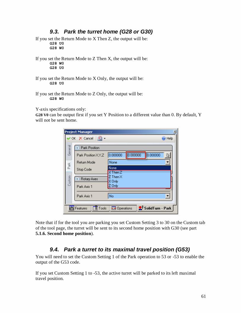
9.2. Park a tool at specific programmed location
On the Park tab of the Park operation page, set the Return Mode to None. The tool will be
parked at the (X; Y; Z) position specified under Park Position. The turret will move the
three axes to the specified point at the same time.
Note: The (X; Y; Z) position programmed in ESPRIT is absolute in YZX. So the post
processors will compute the correct values from this absolute position based on the turret
in use and the spindle on which the park is programmed on.
61
9.3. Park the turret home (G28 or G30)
If you set the Return Mode to X Then Z, the output will be: G28 U0
G28 W0
If you set the Return Mode to Z Then X, the output will be: G28 W0
G28 U0
If you set the Return Mode to X Only, the output will be: G28 U0
If you set the Return Mode to Z Only, the output will be: G28 W0
Y-axis specifications only:
G28 V0 can be output first if you set Y Position to a different value than 0. By default, Y
will not be sent home.
Note that if for the tool you are parking you set Custom Setting 3 to 30 on the Custom tab
of the tool page, the turret will be sent to its second home position with G30 (see part
5.1.6. Second home position).
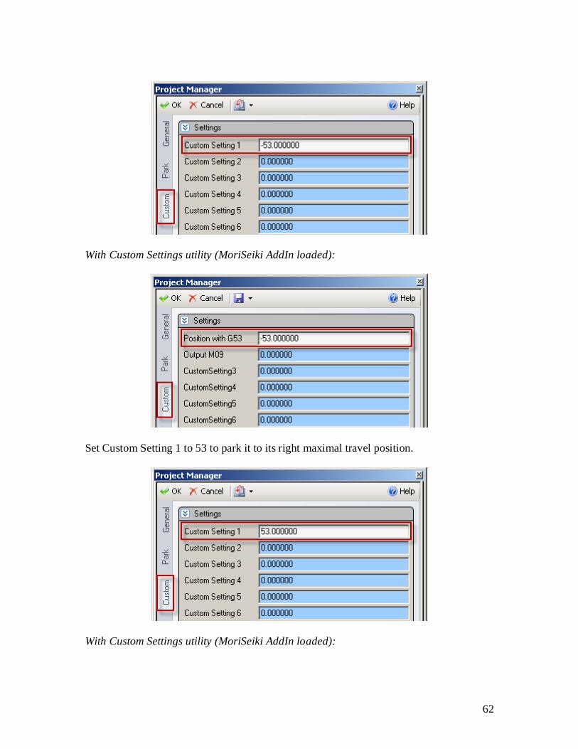
9.4. Park a turret to its maximal travel position (G53)
You will need to set the Custom Setting 1 of the Park operation to 53 or -53 to enable the
output of the G53 code.
If you set Custom Setting 1 to -53, the active turret will be parked to its left maximal
travel position.
62
With Custom Settings utility (MoriSeiki AddIn loaded):
Set Custom Setting 1 to 53 to park it to its right maximal travel position.
With Custom Settings utility (MoriSeiki AddIn loaded):

63
Turrets maximum travel position values (in the machine coordinate system G53):
Upper left turret T1:
Left position: -280 mm
Right position: 0 mm
Upper right turret T2:
Left position: 0 mm
Right position: 280 mm
Sample NC code: N5 (SPINDLE-1 PARK)
(T0202 TURNING INSERT)
G28 U0
G28 V0 W0
G00 T0202
M05
G53 Z-280.0
Note that if the tool you are parking is the same as the previous tool in use, the turret will
be sent home in Y (Y-axis specifications only) then X before the G53 output as a safety.
9.5. Park a turret prior to a transfer
By default, for all turrets, tool station 1 will be called prior to a transfer. As seen in part
4.4.5. Tool station for part transfer and work unloader, this tool station can be
changed using the Custom Setting 4 and 5 of the Machine Setup.
Once correctly setup, you can park turrets using the Park cycle (with G53) prior to a
transfer.
You will first need to create a dummy tool on the turret you need to park, in the right
station. Set the Tool Number to 1 (or whatever you set up in the machine setup) and the
Length Comp Register to 0, or simply set the Tool Number to 100 (or whatever you set
up in the machine setup time 100) and the Length Comp Register to the same number.

64
Then, simply program a Park operation using this previously defined tool prior to the
transfer sequence. Note that since the tool call will be made without tool wear offset
number, you will need to set the Custom Setting 1 to 53 (or -53, see part 9.4. Park a
turret to its maximal travel position (G53)) on the Park operation Custom tab. The
turret will be parked using G53.
Sample NC code: N45 (PARK)
(T0100 DUMMY TOOL UPPER RIGHT)
G28 U0
G28 V0 W0

65
G00 T0100
M05
G53 Z280.0
M110
M01
N1000 (TRANSFER)
M09
M05
M69
G98 G18 M46
G54
Note: If you omit to enter 53 in the Custom Setting 1 of the Park operation, you will get
the following error message in your NC code: ERROR: NO TOOL WEAR OFFSET:
SET CUSTOM SETTING 1 OF PARK TO 53.
9.6. Other functionalities
If you set the Custom Setting 2 to 1 on the Custom tab of the Park operation, the coolants
will be stopped.
With Custom Settings utility (MoriSeiki AddIn loaded):

66
On the Park tab of the operation, if you set Stop Code to Optional Stop or Stop, a Spindle
Rotation Stop Code (M05) will be output.
Sample NC code with coolant stopped and spindle stopped: N10 (SPINDLE-1 PARK)
M09
M05
G28 V0
G28 U0
G53 Z280.0

67
10. How to program finished part catching and part transfer
10.1. Introduction
In this following part, you will be given detailed instructions on how to manually
program various catching of finished part and various part transfers in ESPRIT. A
correct program in ESPRIT is necessary to have a correct NC code.
Please note that the following part catching and part transfer scenarios can be
programmed automatically using the Workpiece Transfer add-in.
10.2. Finished part catching
10.2.1. Catching finished part on spindle 1 side after cut-off
This type of part release comes at the end of the operation list.
It can be performed if your machine is equipped with a receiver on the spindle 1 side.
Note: On the General tab of the Machine Setup, set the Start Position Z:
Start Position Z = Length of stock for facing the front side of the part
The regular steps to follow are:
1. Machining the part on the spindle 1 side
2. Perform a cut-off operation
Steps to program this part ejection type in ESPRIT:
1. Machining the part on the spindle 1 side.
2. Cut-off:
Use operation Cutoff using Upper Left Turret tool on MainSpindle (Spindle
Name).
Cut-off tool is always loaded in the upper left turret for Mori Seiki NZ Series. The
post processors handle cut-off operation programmed in upper left turret only.

68
To trigger the part catching output, set Use Part Catcher to Yes on the Strategy
tab.
Sample operation list:
Sample NC code (head 1): N5 (CUTOFF)
(T1616 CUTOFF INSERT UPPER LEFT)
G28 U0
G28 V0 W0

69
G54
G00 T1616
M69
G99 G18 M46
G97 S2000 M03
G00 Y0.0 Z-103.0
X220.0 M08
X104.0
M73 (Work unloader OUT)
G01 X0.0 F0.05
X-1.0
M74 (Work unloader IN)
10.2.2. Catching finished part on spindle 1 side after cut-off with stock repositioning (programmed first)
If your machine is equipped with a barfeeder, you can reposition the stock, machine the
part, catch the finished part on spindle 1 side and finally loop for the next part.
Note: On the General tab of the Machine Setup, set the Start Position Z:
Start Position Z = - (Length of the finished part (Part Stock Length) + Cut-off tool width
+ Length of stock for facing the back side of the part (if needed))
The steps to follow are the same as previous point. The only difference is that you need to
program a barfeed (by stopper) operation first:
1. Perform a barfeed operation
2. Machining the part on the spindle 1 side
3. Perform a cut-off operation
4. Looping for next parts
Steps to program this part ejection type in ESPRIT:
1. Perform a barfeed operation:
Use operation Bar Feed By Stopper (Bar Feed Type) using Upper Left Turret
tool on MainSpindle (Spindle Name).
On Bar Feed tab, set the Feed Length and Reposition Distance:
Feed Length (=Barfeed distance) = Length of the finished part (Part Stock

70
Length) + Cut-off tool width + Length of stock for facing the front side and, if
needed, the back side of the part
Reposition Distance = 0
With Position X, Y, Z, set the barfeed reference point. Its Z coordinate value
should be equal to the length of stock for facing the front side of the part (if
needed).
The stopper tool will either be positioned in the G53 work coordinate or the
current machine work coordinate.
To use G53 work coordinate: On the Custom tab, enter in the Custom Setting 4
field the X position (in G53 work coordinate) of the stopper tool and in Custom
Setting 5 field the Z position (in G53 work coordinate) of the stopper tool.

71
With Custom Settings utility (MoriSeiki AddIn loaded):
To use current machine work coordinate defined in ESPRIT (see part 2.3.
Turning Work Coordinates): If no value is specified on the Custom tab in the
Custom Setting 4 and 5 fields (Custom Setting 4 and 5 fields left equal to 0), the
stopper tool will be positioned at the programmed position (Position X, Y, Z
specified on Bar Feed tab) in the current active machine work coordinate.
Note that using Custom String 9 in the Machine Setup, you can output the end of
bar macro call (/2 M98 Pxxxx); see part 4.4.9. Output of the end of bar macro
call (/2 M98 Pxxxx).
2. Machining the part on the spindle 1 side.
3. Cut-off:
Use operation Cutoff using Upper Left Turret tool on MainSpindle (Spindle
Name).
Cut-off tool is always loaded in the upper left turret for Mori Seiki NZ Series. The
post processors handle cut-off operation programmed in upper left turret only.
To trigger the part catching output, set Use Part Catcher to Yes on the Strategy
tab.

72
Sample operation list:
Sample NC code (head 1; Bar stopper tool positioned with G53): N1500 (BARFEED)
(T1500 BAR STOPPER)
G28 U0
G28 V0 W0
G00 T1500
M09

73
G53 Z-100.0
G53 X-50.0
M05
M51
M11
G04 U1.0
M70
G04 U1.0
M10
G04 U1.0
M59
G00 W10.0
G28 U0
G28 V0 W0
M05
M01
N5 (SPINDLE-1 FACING)
(T0101 TURNING INSERT OD UPPER LEFT)
G28 U0
G28 V0 W0
G54
G00 T0101
M69
G99 G18 M46
G50 S5000
G97 S1155 M03
G00 Y0.0 Z0.0
X124.0 M08
G96 S450
X119.238
G01 X-0.762 F0.025
Z2.5
G00 X124.0
G97 S1155
M09
G28 U0
G28 V0 W0
M05
M01
10.2.3. Catching finished part on spindle 1 side after cut-off with stock repositioning (programmed last)
If your machine is equipped with a barfeeder, you can after catching the finished part on
spindle 1 side reposition the stock. This way, you can loop for the next part.
Note: On the General tab of the Machine Setup, set the Start Position Z:
Start Position Z = Length of stock for facing the front side of the part

74
The steps to follow are the same as previous point. The only difference is that you need to
program a barfeed (by stopper) operation last:
1. Machining the part on the spindle 1 side
2. Perform a cut-off operation
3. Perform a barfeed operation
4. Looping for next parts
Steps to program this part ejection type in ESPRIT:
1. Machining the part on the spindle 1 side.
2. Cut-off:
Use operation Cutoff using Upper Left Turret tool on MainSpindle (Spindle
Name).
Cut-off tool is always loaded in the upper left turret for Mori Seiki NZ Series. The
post processors handle cut-off operation programmed in upper left turret only.
To trigger the part catching output, set Use Part Catcher to Yes on the Strategy
tab.

75
3. Perform a barfeed operation:
Use operation Bar Feed By Stopper (Bar Feed Type) using Upper Left Turret
tool on MainSpindle (Spindle Name).
On Bar Feed tab, set the Feed Length and Reposition Distance:
Feed Length (=Barfeed distance) = Length of the finished part (Part Stock
Length) + Cut-off tool width + Length of stock for facing the front side and, if
needed, the back side of the part
Reposition Distance = 0
With Position X, Y, Z, set the barfeed reference point. Its Z coordinate value
should be equal to the length of stock for facing the front side of the next part (if
needed).

76
The stopper tool will either be positioned in the G53 work coordinate or the
current machine work coordinate.
To use G53 work coordinate: On the Custom tab, enter in the Custom Setting 4
field the X position (in G53 work coordinate) of the stopper tool and in Custom
Setting 5 field the Z position (in G53 work coordinate) of the stopper tool.
With Custom Settings utility (MoriSeiki AddIn loaded):

77
To use current machine work coordinate defined in ESPRIT (see part 2.3.
Turning Work Coordinates): If no value is specified on the Custom tab in the
Custom Setting 4 and 5 fields (Custom Setting 4 and 5 fields left equal to 0), the
stopper tool will be positioned at the programmed position (Position X, Y, Z
specified on Bar Feed tab) in the current active machine work coordinate.
Note that using Custom String 9 in the Machine Setup, you can output the end of
bar macro call (/2 M98 Pxxxx); see part 4.4.9. Output of the end of bar macro
call (/2 M98 Pxxxx).
Sample operation list:
78
Sample NC code (head 1; Bar stopper tool positioned with G00 in G54): N10 (CUTOFF)
(T1616 CUTOFF INSERT UPPER LEFT)
G28 U0
G28 V0 W0
G54
G00 T1616
M69
G99 G18 M46
G50 S5000
G97 S568 M03
G00 Y0.0 Z-103.0
X112.0 M08
G96 S200
X104.0
M73
G01 X0.0 F0.05
X-1.0
G00 X112.0
G97 S568
M74
M09
G28 U0
G28 V0 W0
M05
M01
N1500 (BARFEED)
(T1515 BAR STOPPER)
G28 U0
G28 V0 W0
G54
G00 T1515
M09
G00 Z1.0
X0.0
M05
M51
M11
G04 U1.0
M70
G04 U1.0
M10
G04 U1.0
M59
G00 W10.0
G28 U0
G28 V0 W0
M05
M01
10.2.4. Manually catching finished part on spindle 1 side
This type of part release is performed when the part is completely machined on spindle 1
side.

79
The regular steps to follow are:
1. Machining the part on the spindle 1 side
2. Manually catching the finished part in the spindle 1
Steps to program this part ejection type in ESPRIT:
1. Machining the parts on the spindle 1 side.
2. Manually catching the finished part in the spindle 1 (head 1 is stopped with M00):
To be able to manually catch the finished part in the spindle 1, head 1 needs to be
stopped using M-code M00 (program stop).
Use operation Release with MainSpindle (Spindle Name) on Upper Left
Turret (Turret Name).
To trigger the output of M00 in head 1, set Part Chute to No on the Release tab.
Sample operation list of manual finished part catching:
Sample NC code of manual part catching: N500 (RELEASE)
M00

80
10.2.5. Catching finished part on spindle 2 side
This type of part release is performed when the part is completely machined on spindle 2
side.
The regular steps to follow are:
1. Machining the part on the spindle 2 side
2. Catching the finished part in the spindle 2
Steps to program this part ejection type in ESPRIT:
1. Machining the part on the spindle 2 side:
Note: The operations on the spindle 2 side are output with the origin shifted to the
other face of the part (back face). During operations, only positive Z coordinates
are output.
The setting “Part Stock Length” from the Machine Setup is used as default value
for Turning Work Coordinates Sub Spindle Z Offset.
CAUTION !!! Part Stock Length = Finished Part Length. You must run the
Turning Work Coordinates add-in prior to posting NC Code in order to have
correct NC output.
2. Catching the finished part in the spindle 2:
Use operation Release with SubSpindle (Spindle Name) on Upper Right
Turret (Turret Name).
The release operation has to be programmed with upper right turret because the
upper right turret controls the B-axis (spindle 2).
Based on the value entered in Custom Setting 2 field of the machine setup (see
part 4.4.4. Work unloader on spindle 2 side: hand or receiver), the NC output
will differ to match your machine specifications: hand or receiver equipped.
Catching the finished part in the spindle 2 on a machine equipped with a hand or a
receiver:
To trigger the part catching output, set Part Chute to Yes on the Release tab.
In the Custom Setting 8 field of the SolidTurn Release operation page, enter the
part catching position. The spindle 2 will rapid to this position. Note that you can
enter a positive or negative value, the output position will always be negative
since it is output in the machine work coordinate (G53).

81
On a machine equipped with a receiver, with Custom Setting 9, you can specify
how you want to eject the finished part: set Custom Setting 9 to 47 if you have the
workpiece ejector OUT (M47) equipped on the machine, to 360 if you have the
workpiece ejector OUT (M360), IN (M361) option. If you omit to enter a value in
Custom Setting 9 or enter a wrong value, no part ejection code will be output in
the NC code.
With Custom Settings utility (MoriSeiki AddIn loaded):

82
Manually catching the finished part in the spindle 2 (head 2 is stopped with M00):
To be able to manually catch the finished part in the spindle 2, head 2 needs to be
stopped using M-code M00 (program stop).
To trigger the output of M00 in head 2, set Part Chute to No on the Release tab.
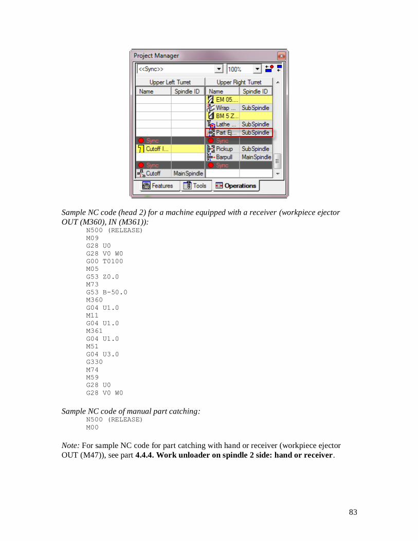
Sample operation list of finished part catching (with arm, receiver or manual):
83
Sample NC code (head 2) for a machine equipped with a receiver (workpiece ejector
OUT (M360), IN (M361)): N500 (RELEASE)
M09
G28 U0
G28 V0 W0
G00 T0100
M05
G53 Z0.0
M73
G53 B-50.0
M360
G04 U1.0
M11
G04 U1.0
M361
G04 U1.0
M51
G04 U3.0
G330
M74
M59
G28 U0
G28 V0 W0
Sample NC code of manual part catching: N500 (RELEASE)
M00
Note: For sample NC code for part catching with hand or receiver (workpiece ejector
OUT (M47)), see part 4.4.4. Work unloader on spindle 2 side: hand or receiver.
84
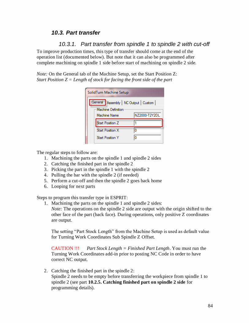
10.3. Part transfer
10.3.1. Part transfer from spindle 1 to spindle 2 with cut-off
To improve production times, this type of transfer should come at the end of the
operation list (documented below). But note that it can also be programmed after
complete machining on spindle 1 side before start of machining on spindle 2 side.
Note: On the General tab of the Machine Setup, set the Start Position Z:
Start Position Z = Length of stock for facing the front side of the part
The regular steps to follow are:
1. Machining the parts on the spindle 1 and spindle 2 sides
2. Catching the finished part in the spindle 2
3. Picking the part in the spindle 1 with the spindle 2
4. Pulling the bar with the spindle 2 (if needed)
5. Perform a cut-off and then the spindle 2 goes back home
6. Looping for next parts
Steps to program this transfer type in ESPRIT:
1. Machining the parts on the spindle 1 and spindle 2 sides:
Note: The operations on the spindle 2 side are output with the origin shifted to the
other face of the part (back face). During operations, only positive Z coordinates
are output.
The setting “Part Stock Length” from the Machine Setup is used as default value
for Turning Work Coordinates Sub Spindle Z Offset.
CAUTION !!! Part Stock Length = Finished Part Length. You must run the
Turning Work Coordinates add-in prior to posting NC Code in order to have
correct NC output.
2. Catching the finished part in the spindle 2:
Spindle 2 needs to be empty before transferring the workpiece from spindle 1 to
spindle 2 (see part 10.2.5. Catching finished part on spindle 2 side for
programming details).

85
3. Program a wait code (sync) across the two heads.
4. Picking the part in the spindle 1 with the spindle 2:
Use operation Pickup with SubSpindle (Spindle Name) on Upper Right Turret
(Turret Name). With Position X, Y, Z, set the pickup point.
The pickup operation has to be programmed with upper right turret because the
upper right turret controls the B-axis (spindle 2).
Set Sync Spindles to Speed and Direction Only (or to Off) for speed
synchronization code output (M35) or to Oriented for phase synchronization code
output (M34). The spindle speed entered on the SolidTurn Pickup page will be
output on head 1 after synchronization of the spindles.
Enter the Feedrate PM of the spindle 2 B-axis and its clearance (from the pickup
point); it will be output in head 2 program (since head 2 controls the B-axis).

86
5. Pulling the bar with the spindle 2 (if needed):
Use operation Bar Feed by Spindle (Bar Feed Type) on MainSpindle (Spindle
Name) by SubSpindle (Barfeed Spindle Name).
Set Turret Name to Upper Right Turret.
On Bar Feed tab, set the Feed Length and Reposition Distance:
Feed Length (= Barpull distance = Reposition Distance) = Length of the finished
part (Part Stock Length) + Cut-off tool width + Length of stock for facing the
front side and the back side of the part
With Position X, Y, Z, set the same point as for the pickup operation (If the
point is different, chucks will unclamp and clamp before pulling the bar).

87
Programming a pickup before the barpull makes the spindle 2 stay at the same
location after the barpull. Without pickup operation, spindle 2 goes home after the
barpull.
On the General tab, enter the Feedrate PM of the spindle 2 B-axis, it will be
output in head 2 program (since head 2 controls the B-axis).
6. Program a wait code (sync) across the two heads.
7. Cut-off:
Use operation Cutoff using Upper Left Turret tool on MainSpindle (Spindle
Name).
Cut-off tool is always loaded in the upper left turret for Mori Seiki NZ Series. The
post processors handle cut-off operation programmed in upper left turret only.
To output a dwell (G04 U) above workpiece cut-off detection (M80), enter in the
Dwell Time field on the Rough tab of the Cutoff operation the dwell time in s.

88
The spindle 2 automatically goes home after cut-off completion.
CAUTION!!! Make sure to move the cut-off toolchange above the last
programmed sync.
Sample operation list with transfer (with barpull) and cut-off:

89
Sample operation list with transfer (without barpull) and cut-off:
Sample NC code (barpull programmed):
Upper left turret Upper right turret M102 M102
M01 M01

90
N1000 (TRANSFER) N1000 (TRANSFER)
N100 (CUTOFF) M69
(T1616 CUTOFF INSERT UPPER
LEFT) G98 G18 M46
G28 U0 G54
G28 V0 W0 M11
G54 G04 U1.0
G00 T1616
M05
M09
M69
M46
M103 M103
M34 M34
M104 M104
G97 S500 M04 M51
M51 M385
G00 B50.0
G04 U1.0
G01 B20.0 F250.0
M10
G04 U1.0
M59
M105 M105
M11
G04 U1.0
M106 M106
G01 B61.0 F250.0
M107 M107
M10
G04 U1.0
M59
M108 M108
N2000 (CUTOFF) N2000 (CUTOFF)
M69
G99 G18 M46
G50 S5000
G97 S217 M04
G00 Y0.0 Z1.0
X220.0 M08
G96 S150
X64.0
G01 X0.0 F0.15
X-1.0

91
G97 S5000
G28 U0
M80
M109 M109
M51 M36
G330
M386
G99
M110 M110
M59
M09
G28 U0
G28 V0 W0
M05
M01
10.3.2. Part transfer from spindle 1 to spindle 2 with cut-off (when machine equipped with a barfeeder)
If your machine is equipped with a barfeeder, instead of pulling the part from spindle 1,
you can use the barfeeder to position the bar before pickup and cut-off.
To improve production times, this type of transfer should come at the end of the
operation list (documented below). But note that it can also be programmed after
complete machining on spindle 1 side before start of machining on spindle 2 side.
Note: On the General tab of the Machine Setup, set the Start Position Z:
Start Position Z = Length of stock for facing the front side of the part
The regular steps to follow are:
1. Machining the parts on the spindle 1 and spindle 2 sides
2. Catching the finished part in the spindle 2
3. Perform a barfeed operation
4. Picking the part in the spindle 1 with the spindle 2
5. Perform a cut-off and then the spindle 2 goes back home

92
6. Looping for next parts
Steps to program this transfer type in ESPRIT:
1. Machining the parts on the spindle 1 and spindle 2 sides:
Note: The operations on the spindle 2 side are output with the origin shifted to the
other face of the part (back face). During operations, only positive Z coordinates
are output.
The setting “Part Stock Length” from the Machine Setup is used as default value
for Turning Work Coordinates Sub Spindle Z Offset.
CAUTION !!! Part Stock Length = Finished Part Length. You must run the
Turning Work Coordinates add-in prior to posting NC Code in order to have
correct NC output.
2. Catching the finished part in the spindle 2:
Spindle 2 needs to be empty before transferring the workpiece from spindle 1 to
spindle 2 (see part 10.2.5. Catching finished part on spindle 2 side for
programming details).
3. Program a wait code (sync) across the two heads.
4. Perform a barfeed operation:
Use operation Bar Feed By Stopper (Bar Feed Type) using Upper Left Turret
tool on MainSpindle (Spindle Name).
On Bar Feed tab, set the Feed Length and Reposition Distance:
Feed Length (=Barfeed distance = Reposition Distance) = Length of the finished
part (Part Stock Length) + Cut-off tool width + Length of stock for facing the
front side and the back side of the part
With Position X, Y, Z, set the barfeed reference point. Its Z coordinate value
should be equal to the entered feed length.

93
The stopper tool will either be positioned in the G53 work coordinate or the
current machine work coordinate.
To use G53 work coordinate: On the Custom tab, enter in the Custom Setting 4
field the X position (in G53 work coordinate) of the stopper tool and in Custom
Setting 5 field the Z position (in G53 work coordinate) of the stopper tool.
With Custom Settings utility (MoriSeiki AddIn loaded):

94
To use current machine work coordinate defined in ESPRIT (see part 2.3.
Turning Work Coordinates): If no value is specified on the Custom tab in the
Custom Setting 4 and 5 fields (Custom Setting 4 and 5 fields left equal to 0), the
stopper tool will be positioned at the programmed position (Position X, Y, Z
specified on Bar Feed tab) in the current active machine work coordinate.
Note that using Custom String 9 in the Machine Setup, you can output the end of
bar macro call (/2 M98 Pxxxx); see part 4.4.9. Output of the end of bar macro
call (/2 M98 Pxxxx).
5. Program a wait code (sync) across the two heads.
6. Picking the part in the spindle 1 with the spindle 2:
Use operation Pickup with SubSpindle (Spindle Name) on Upper Right Turret
(Turret Name). With Position X, Y, Z, set the pickup point. Note that the pickup
point will be shifted by the reposition distance amount entered on Bar Feed tab of
Bar Feed operation.
The pickup operation has to be programmed with upper right turret because the
upper right turret controls the B-axis (spindle 2).
Set Sync Spindles to Speed and Direction Only (or to Off) for speed
synchronization code output (M35) or to Oriented for phase synchronization code
output (M34). The spindle speed entered on the SolidTurn Pickup page will be
output on head 1 after synchronization of the spindles.

95
Enter the Feedrate PM of the spindle 2 B-axis and its clearance (from the pickup
point); it will be output in head 2 program (since head 2 controls the B-axis).
7. Program a wait code (sync) across the two heads.
8. Cut-off:
Use operation Cutoff using Upper Left Turret tool on MainSpindle (Spindle
Name).
Cut-off tool is always loaded in the upper left turret for Mori Seiki NZ Series. The
post processors handle cut-off operation programmed in upper left turret only.

96
To output a dwell (G04 U) above workpiece cut-off detection (M80), enter in the
Dwell Time field on the Rough tab of the Cutoff operation the dwell time in s.
The spindle 2 automatically goes home after cut-off completion.
CAUTION!!! Make sure to move the cut-off toolchange above the last
programmed sync.
Sample operation list:

97
Sample NC code:
Upper left turret Upper right turret
M102 M102
M01 M01
N1000 (TRANSFER) N1000 (TRANSFER)
N1500 (BARFEED)
(T1500 BAR STOPPER Z+ UPPER
LEFT)
G28 U0
G28 V0 W0
G00 T1500
M09
G53 Z-4.0
G53 X-2.0
M05
M51
M11
G04 U1.0
M70
G04 U1.0
M10
G04 U1.0
M59
G00 W0.394
G28 U0

98
G28 V0 W0
M103 M103
N60 (CUTOFF) M09
(T1676 CUTOFF INSERT UPPER
LEFT) G28 U0
G28 U0 G28 V0 W0
G28 V0 W0 G00 T0100
G54 M05
G00 T1676 M69
M05 G98 G18 M46
M69 G54
M46 M11
G04 U1.0
M104 M104
M35 M35
M105 M105
G97 S500 M04 M51
M51 M385
G00 B4.7181
G04 U1.0
G01 B4.6181 F10.0
M10
G04 U1.0
M59
M106 M106
M59
M107 M107
N2000 (CUTOFF) N2000 (CUTOFF)
M69
G99 G18 M46
G50 S5000
G97 S82 M04
G00 Y0.0 Z0.0
X7.0 M08
G96 S150
X3.3
G01 X0.0 F0.15
X-0.254
G97 S2256
G28 U0
M80
M108 M108
M51 M36
G330

99
M386
G99
M109 M109
M59
M09
G28 U0
G28 V0 W0
M05
M01
10.3.3. Part transfer from spindle 1 to spindle 2 with cut-off and stock repositioning (programmed last)
If your machine is equipped with a barfeeder, you can after transferring the finished part
from spindle 1 to spindle 2 reposition the stock. This way, you can loop for the next part.
To improve production times, this type of transfer should come at the end of the
operation list (documented below). But note that it can also be programmed after
complete machining on spindle 1 side before start of machining on spindle 2 side.
Note: On the General tab of the Machine Setup, set the Start Position Z:
Start Position Z = Length of stock for facing the front side of the part
The regular steps to follow are:
1. Machining the parts on the spindle 1 and spindle 2 sides
2. Catching the finished part in the spindle 2
3. Picking the part in the spindle 1 with the spindle 2
4. Perform a cut-off and then the spindle 2 goes back home
5. Perform a barfeed operation
6. Looping for next parts
Steps to program this transfer type in ESPRIT:
1. Machining the parts on the spindle 1 and spindle 2 sides:
Note: The operations on the spindle 2 side are output with the origin shifted to the
other face of the part (back face). During operations, only positive Z coordinates

100
are output.
The setting “Part Stock Length” from the Machine Setup is used as default value
for Turning Work Coordinates Sub Spindle Z Offset.
CAUTION !!! Part Stock Length = Finished Part Length. You must run the
Turning Work Coordinates add-in prior to posting NC Code in order to have
correct NC output.
2. Catching the finished part in the spindle 2:
Spindle 2 needs to be empty before transferring the workpiece from spindle 1 to
spindle 2 (see part 10.2.5. Catching finished part on spindle 2 side for
programming details).
3. Program a wait code (sync) across the two heads.
4. Picking the part in the spindle 1 with the spindle 2:
Use operation Pickup with SubSpindle (Spindle Name) on Upper Right Turret
(Turret Name). With Position X, Y, Z, set the pickup point.
The pickup operation has to be programmed with upper right turret because the
upper right turret controls the B-axis (spindle 2).
Set Sync Spindles to Speed and Direction Only (or to Off) for speed
synchronization code output (M35) or to Oriented for phase synchronization code
output (M34). The spindle speed entered on the SolidTurn Pickup page will be
output on head 1 after synchronization of the spindles.
Enter the Feedrate PM of the spindle 2 B-axis and its clearance (from the pickup
point); it will be output in head 2 program (since head 2 controls the B-axis).

101
5. Program a wait code (sync) across the two heads.
6. Cut-off:
Use operation Cutoff using Upper Left Turret tool on MainSpindle (Spindle
Name).
Cut-off tool is always loaded in the upper left turret for Mori Seiki NZ Series. The
post processors handle cut-off operation programmed in upper left turret only.
To output a dwell (G04 U) above workpiece cut-off detection (M80), enter in the
Dwell Time field on the Rough tab of the Cutoff operation the dwell time in s.

102
The spindle 2 automatically goes home after cut-off completion.
CAUTION!!! Make sure to move the cut-off toolchange above the last
programmed sync.
7. Perform a barfeed operation:
Use operation Bar Feed By Stopper (Bar Feed Type) using Upper Left Turret
tool on MainSpindle (Spindle Name).
On Bar Feed tab, set the Feed Length and Reposition Distance:
Feed Length (=Barfeed distance = Reposition Distance) = Length of the finished
part (Part Stock Length) + Cut-off tool width + Length of stock for facing the
front side and the back side of the part
With Position X, Y, Z, set the barfeed reference point. Its Z coordinate value
should be equal to the length of stock for facing the front side (of the next part).

103
The stopper tool will either be positioned in the G53 work coordinate or the
current machine work coordinate.
To use G53 work coordinate: On the Custom tab, enter in the Custom Setting 4
field the X position (in G53 work coordinate) of the stopper tool and in Custom
Setting 5 field the Z position (in G53 work coordinate) of the stopper tool.
With Custom Settings utility (MoriSeiki AddIn loaded):

104
To use current machine work coordinate defined in ESPRIT (see part 2.3.
Turning Work Coordinates): If no value is specified on the Custom tab in the
Custom Setting 4 and 5 fields (Custom Setting 4 and 5 fields left equal to 0), the
stopper tool will be positioned at the programmed position (Position X, Y, Z
specified on Bar Feed tab) in the current active machine work coordinate.
Note that using Custom String 9 in the Machine Setup, you can output the end of
bar macro call (/2 M98 Pxxxx); see part 4.4.9. Output of the end of bar macro
call (/2 M98 Pxxxx).
Sample operation list with transfer, cut-off and barfeed (last):
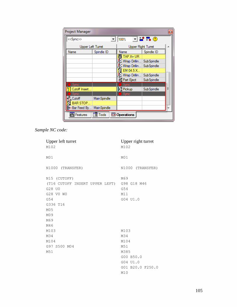
105
Sample NC code:
Upper left turret Upper right turret
M102 M102
M01 M01
N1000 (TRANSFER) N1000 (TRANSFER)
N15 (CUTOFF) M69
(T16 CUTOFF INSERT UPPER LEFT) G98 G18 M46
G28 U0 G54
G28 V0 W0 M11
G54 G04 U1.0
G336 T16
M05
M09
M69
M46
M103 M103
M34 M34
M104 M104
G97 S500 M04 M51
M51 M385
G00 B50.0
G04 U1.0
G01 B20.0 F250.0
M10

106
G04 U1.0
M59
M105 M105
M59
M106 M106
N2000 (CUTOFF) N2000 (CUTOFF)
M69
G99 G18 M46
G50 S5000
G97 S217 M04
G00 Y0.0 Z-39.0
X220.0 M08
G96 S150
X64.0
G01 X0.0 F0.15
X-1.0
G97 S5000
G28 U0
M80
M107 M107
M51 M36
G330
M386
G99
M108 M108
M59
M09
M300
G28 U0
G28 V0 W0
M05
M01
N1500 (BARFEED)
(T1500 BAR STOPPER Z+ UPPER
LEFT)
G28 U0
G28 V0 W0
G00 T1500
M09
G53 Z-100.0
G53 X-50.0
M05
M51
M11
G04 U1.0

107
M70
G04 U1.0
M10
G04 U1.0
M59
G00 W10.0
G28 U0
G28 V0 W0
M05
M01
10.3.4. Part transfer from spindle 1 to spindle 2 without cut-off
The stock is manually loaded in the spindle 1; the part is not pulled. The finished part in
the spindle 2 has to be released. The entire part is transferred to the spindle 2 when the
work on spindle 1 is finished.
To improve production times, this type of transfer should come at the end of the
operation list (documented below). But note that it can also be programmed after
complete machining on spindle 1 side before start of machining on spindle 2 side.
Note: On the General tab of the Machine Setup, set the Start Position Z and Total Bar
Length:
Start Position Z = Length of stock for facing the front side of the part
Total Bar Length = Length of the finished part (Part Stock Length) + Length of stock for
facing the front side and the back side of the part

108
The regular steps to follow are:
1. Machining the parts on the spindle 1 and spindle 2 sides
2. Catching the finished part in the spindle 2
3. Picking the part in the spindle 1 with the spindle 2
4. Releasing the part from the spindle 1 and then the spindle 2 goes back home
5. Stop for loading a new stock in the spindle 1
Steps to program this transfer type in ESPRIT:
1. Machining the parts on the spindle 1 and spindle 2 sides:
Note: The operations on the spindle 2 side are output with the origin shifted to the
other face of the part (back face). During operations, only positive Z coordinates
are output.
The setting “Part Stock Length” from the Machine Setup is used as default value
for Turning Work Coordinates Sub Spindle Z Offset.
CAUTION !!! Part Stock Length = Finished Part Length. You must run the
Turning Work Coordinates add-in prior to posting NC Code in order to have
correct NC output.
2. Catching the finished part in the spindle 2:
Spindle 2 needs to be empty before transferring the workpiece from spindle 1 to
spindle 2 (see part 10.2.5. Catching finished part on spindle 2 side for
programming details).
3. Program a wait code (sync) across the two heads.
4. Picking the part in the spindle 1 with the spindle 2:
Use operation Pickup with SubSpindle (Spindle Name) on Upper Right Turret
(Turret Name). With Position X, Y, Z, set the pickup point.
The pickup operation has to be programmed with upper right turret because the
upper right turret controls the B-axis (spindle 2).
Enter the Feedrate PM of the spindle 2 B-axis and its clearance (from the pickup
point); it will be output in head 2 program (since head 2 controls the B-axis).
During this type of transfer, the turning spindles are stopped. Using the Custom
Setting 6 on the Custom tab of the Pickup operation, you can specify how you
want to orient your spindles. Set Custom Setting 6 to 19 if you want to use spindle
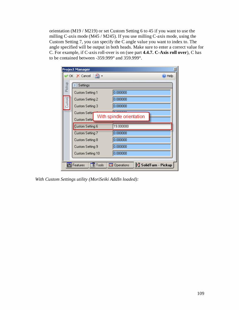
109
orientation (M19 / M219) or set Custom Setting 6 to 45 if you want to use the
milling C-axis mode (M45 / M245). If you use milling C-axis mode, using the
Custom Setting 7, you can specify the C angle value you want to index to. The
angle specified will be output in both heads. Make sure to enter a correct value for
C. For example, if C-axis roll-over is on (see part 4.4.7. C-Axis roll over), C has
to be contained between -359.999° and 359.999°.
With Custom Settings utility (MoriSeiki AddIn loaded):

110
With Custom Settings utility (MoriSeiki AddIn loaded):

111
Note that the milling C-axis mode is the default. So if you omit to enter a value in
Custom Setting 6 or enter a wrong value, the spindles will be indexed using this
mode.
5. Program a wait code (sync) across the two heads.
6. Releasing the part from the spindle 1:
Use operation Release with MainSpindle (Spindle Name) on Upper Left
Turret (Turret Name). With Position X, Y, Z, set the release point.
Sample operation list:

112
Sample NC code (with milling C-axis mode):
Upper left turret Upper right turret
M102 M102
M01 M01
N1000 (TRANSFER) N1000 (TRANSFER)
M09 M69
G28 U0 G98 G18 M45
G28 V0 W0 G54
G00 T0100 M11
M05 G04 U1.0
M69 G28 H0
M45 G00 C0.0
G28 H0
G54
G00 C0.0
M103 M103
M51 M51
M385
G00 B50.0
G04 U1.0
G01 B32.0 F250.0
M10
G04 U1.0
M59

113
M104 M104
M11
G04 U1.0
M59
M105 M105
G330
M386
G99
M106 M106
10.3.5. Part transfer from spindle 2 to spindle 1 without cut-off
The stock is manually loaded in the spindle 2; the part is not pulled. The finished part has
to be manually unloaded from the spindle 1. The entire part is transferred to the spindle 1
when the work on spindle 2 is finished.
To improve production times, this type of transfer should come at the end of the
operation list (documented below). But note that it can also be programmed after
complete machining on spindle 2 side before start of machining on spindle 1 side.
Note: On the General tab of the Machine Setup, set the Start Position Z:
Start Position Z = Length of stock for facing the front side of the part
Total Bar Length = Length of the finished part (Part Stock Length) + Length of stock for
facing the front side and the back side of the part

114
The regular steps to follow are:
1. Machining the parts on the spindle 1 and spindle 2 sides
2. Manually unloading the finished part in the spindle 1
3. Picking the part in the spindle 2 with the spindle 1
4. Releasing the part from the spindle 2 and then the spindle 2 goes back home
5. Stop for loading a new stock in the spindle 2
Steps to program this transfer type in ESPRIT:
1. Machining the parts on the spindle 1 and spindle 2 sides:
Note: The operations on the spindle 2 side are output with the origin shifted to the
other face of the part (back face). During operations, only positive Z coordinates
are output.
The setting “Part Stock Length” from the Machine Setup is used as default value
for Turning Work Coordinates Sub Spindle Z Offset.
CAUTION !!! Part Stock Length = Finished Part Length. You must run the
Turning Work Coordinates add-in prior to posting NC Code in order to have
correct NC output.
2. Manually unloading the finished part in the spindle 1:
Spindle 1 needs to be empty before transferring the workpiece from spindle 2 to
spindle 1 (see part 10.2.4 . Manually catching finished part on spindle 1 side
for programming details).
3. Program a wait code (sync) across the two heads.
4. Picking the part in the spindle 2 with the spindle 1:
Use operation Pickup with MainSpindle (Spindle Name) on Upper Left Turret
(Turret Name). With Position X, Y, Z, set the pickup point: point that you would
like the back of spindle 1 to reach while picking up the part (usually the zero point
of the part in the spindle 2).
Enter the Feedrate PM of the spindle 2 B-axis and its clearance (from the pickup
point); it will be output in head 2 program (since head 2 controls the B-axis).
During this type of transfer, the turning spindles are stopped. Using the Custom
Setting 6 on the Custom tab of the Pickup operation, you can specify how you
want to orient your spindles. Set Custom Setting 6 to 19 if you want to use spindle
orientation (M19 / M219) or set Custom Setting 6 to 45 if you want to use the

115
milling C-axis mode (M45 / M245). If you use milling C-axis mode, using the
Custom Setting 7, you can specify the C angle value you want to index to. The
angle specified will be output in both heads. Make sure to enter a correct value for
C. For example, if C-axis roll-over is on (see part 4.4.7. C-Axis roll over), C has
to be contained between -359.999° and 359.999°.
With Custom Settings utility (MoriSeiki AddIn loaded):

116
With Custom Settings utility (MoriSeiki AddIn loaded):

117
Note that the milling C-axis mode is the default. So if you omit to enter a value in
Custom Setting 6 or enter a wrong value, the spindles will be indexed using this
mode.
5. Program a wait code (sync) across the two heads.
6. Releasing the part from the spindle 2:
Use operation Release with SubSpindle (Spindle Name) on Upper Right
Turret (Turret Name). With Position X, Y, Z, set the release point.
Sample operation list:

118
Sample NC code (with spindle orientation):
Upper left turret Upper right turret M102 M102
M01 M01
N1000 (TRANSFER) N1000 (TRANSFER)
M09 M09
G28 U0 G28 U0
G28 V0 W0 G28 V0 W0
G00 T0100 G00 T0100
M05 M05
M11 M69
G04 U1.0 G98 G18 M46
M69 G54
M46 M19
G54
M19
M103 M103
M51 M51
M385
G00 B45.0
G04 U1.0
G01 B0.0 F250.0
M104 M104
M10
G04 U1.0
M105 M105

119
M59 M11
G04 U1.0
M59
G330
M386
G99
M106 M106
10.3.6. Stock repositioning
If your machine is not equipped with a barfeeder, using this type of transfer, you will be
able to reposition the stock in spindle 1 using the spindle 2. This type of transfer can be
programmed anywhere in the program.
Note: Spindle 2 needs to be empty before repositioning since spindle 2 will pick up the
part in spindle 1.
The regular steps to follow are:
1. Picking the part in the spindle 1 with the (empty) spindle 2
2. Pulling the bar with the spindle 2
3. Releasing the part from the spindle 2 and then the spindle 2 goes back home
Steps to program this transfer type in ESPRIT:
1. Program a wait code (sync) across the two heads.
2. Picking the part in the spindle 1 with the (empty) spindle 2:
Use operation Pickup with SubSpindle (Spindle Name) on Upper Right Turret
(Turret Name). With Position X, Y, Z, set the pickup point.
The pickup operation has to be programmed with upper right turret because the
upper right turret controls the B-axis (spindle 2).
Enter the Feedrate PM of the spindle 2 B-axis and its clearance (from the pickup
point); it will be output in head 2 program (since head 2 controls the B-axis).
During this type of transfer, the turning spindles are stopped. Using the Custom
Setting 6 on the Custom tab of the Pickup operation, you can specify how you
want to orient your spindles. Set Custom Setting 6 to 19 if you want to use spindle
orientation (M19 / M219) or set Custom Setting 6 to 45 if you want to use the
milling C-axis mode (M45 / M245). If you use milling C-axis mode, using the

120
Custom Setting 7, you can specify the C angle value you want to index to. The
angle specified will be output in both heads. Make sure to enter a correct value for
C. For example, if C-axis roll-over is on (see part 4.4.7. C-Axis roll over), C has
to be contained between -359.999° and 359.999°.
With Custom Settings utility (MoriSeiki AddIn loaded):

121
With Custom Settings utility (MoriSeiki AddIn loaded):
Note that the milling C-axis mode is the default. So if you omit to enter a value in
Custom Setting 6 or enter a wrong value, the spindles will be indexed using this
mode.

122
3. Pulling the bar with the spindle 2:
Use operation Bar Feed by Spindle (Bar Feed Type) on MainSpindle (Spindle
Name) by SubSpindle (Barfeed Spindle Name).
Set Turret Name to Upper Right Turret.
On Bar Feed tab, set the Feed Length and Reposition Distance:
Feed Length = Barpull distance = Length of stock that spindle 2 will pull out of
spindle 1 for repositioning
Reposition Distance = Set it to 0 if you do not want to shift your Z values after
repositioning or set it to Feed Length if you want to shift your Z values by the
repositioning distance value
With Position X, Y, Z, set the same point as for the pickup operation (If the
point is different, chucks will unclamp and clamp before pulling the bar).
Programming a pickup before the barpull makes the spindle 2 stay at the same
location after the barpull. Without pickup operation, spindle 2 goes home after the
barpull.
On the General tab, enter the Feedrate PM of the spindle 2 B-axis, it will be
output in head 2 program (since head 2 controls the B-axis).
4. Releasing the part from the spindle 2:
Use operation Release with SubSpindle (Spindle Name) on Upper Right
Turret (Turret Name). With Position X, Y, Z, set the release point.
5. Program a wait code (sync) across the two heads.

123
Sample operation list:
Sample NC code (with output of the end of bar macro call (/2 M98 Pxxxx)):
Upper left turret Upper right turret
M102 M102
M01 M01
N250 (STOCK REPOSITIONING) N250 (STOCK REPOSITIONING)
M09 M09
G28 U0 G28 U0
G28 V0 W0 G28 V0 W0
G00 T0100 G00 T0100
M05 M05
M69 M69
M45 G98 G18 M45
G28 H0 G54
G54 M11
G00 C0.0 G04 U1.0
G28 H0
G00 C0.0
M103 M103
M51 M51
M385
G00 B-40.0
G04 U1.0
G01 B-70.0 F250.0
M10

124
G04 U1.0
M104 M104
M11
G04 U1.0
M105 M105
/2 M98 P8000 /2 M98 P8000
G01 B36.5 F250.0
M106 M106
M10
G04 U1.0
M107 M107
M59 M11
G04 U1.0
M59
G330
M386
G99
M108 M108
M109 M109
M01 M01
10.3.7. Machining of long parts with spindle 1 and 2 synchronized
To support the stock with both spindles, you first need to pick it up (and, if needed, pull
it) with the spindle 2. You can after program your operations (in head 1) and in the code
will be output the necessary spindles synchronization and unsynchronization codes.
Finally, once machining is completed, you can program one of the transfer scenarios
described in the previous parts at the end of the operation list.
Note: On the General tab of the Machine Setup, set the Start Position Z:
Start Position Z = Length of stock for facing the front side of the part or position of the
stock in spindle 1 before pick up for synchronized machining

125
The regular steps to follow are:
1. Machining the parts on the spindle 1 and spindle 2 sides
2. Catching the finished part in the spindle 2
3. Picking the part in the spindle 1 with the spindle 2
4. Pulling the bar with the spindle 2 (if needed)
5. Machining the part on the spindle 1 side with head 1 while the spindles are
synchronized and are both supporting the part
6. Perform one of the previously described transfer scenarios to transfer the part to
spindle 2 side
7. Looping for next parts
Steps to program this transfer type in ESPRIT:
1. Machining the parts on the spindle 1 and spindle 2 sides:
Note: The operations on the spindle 2 side are output with the origin shifted to the
other face of the part (back face). During operations, only positive Z coordinates
are output.
The setting “Part Stock Length” from the Machine Setup is used as default value
for Turning Work Coordinates Sub Spindle Z Offset.
CAUTION !!! Part Stock Length = Finished Part Length. You must run the
Turning Work Coordinates add-in prior to posting NC Code in order to have
correct NC output.
2. Catching the finished part in the spindle 2:
Spindle 2 needs to be empty before transferring the workpiece from spindle 1 to
spindle 2 (see part 10.2.5. Catching finished part on spindle 2 side for
programming details).
3. Program a wait code (sync) across the two heads.
4. Picking the part in the spindle 1 with the spindle 2:
Use operation Pickup with SubSpindle (Spindle Name) on Upper Right Turret
(Turret Name). With Position X, Y, Z, set the pickup point.
The pickup operation has to be programmed with upper right turret because the
upper right turret controls the B-axis (spindle 2).
Based on the following operation in head 1, the correct synchronization code will
be output in the code:
- M34 (or M35): Turning operation is next on head 1; the spindle speed entered
on the SolidTurn Pickup page will be output on head 1 after synchronization of
the spindles; the spindle direction code will be output on head 1 based on the
direction of the following turning operation.
- M480: Milling operation is next on head 1; the spindles are stopped.

126
Enter the Feedrate PM of the spindle 2 B-axis and its clearance (from the pickup
point); it will be output in head 2 program (since head 2 controls the B-axis).
Note: The synchronization mode selected (as shown on picture above) on the
pickup operation page will be used for all the following turning operations while
the spindles are both holding the part.
5. Pulling the bar with the spindle 2 (if needed):
Use operation Bar Feed by Spindle (Bar Feed Type) on MainSpindle (Spindle
Name) by SubSpindle (Barfeed Spindle Name).
Set Turret Name to Upper Right Turret.
On Bar Feed tab, set the Feed Length and Reposition Distance:

127
Feed Length (= Barpull distance = Reposition Distance)
With Position X, Y, Z, set the same point as for the pickup operation (If the
point is different, chucks will unclamp and clamp before pulling the bar).
Programming a pickup before the barpull makes the spindle 2 stay at the same
location after the barpull. Without pickup operation, spindle 2 goes home after the
barpull.
On the General tab, enter the Feedrate PM of the spindle 2 B-axis, it will be
output in head 2 program (since head 2 controls the B-axis).
6. Program a wait code (sync) across the two heads.
7. Machining the part on the spindle 1 side with head 1 while the spindles are
synchronized and are both supporting the part:
The correct synchronization (and unsynchronization) codes will be output in the
NC code based on the programmed operations.
8. Program a wait code (sync) across the two heads.
9. Perform one of the previously described transfer scenarios to transfer the part to
spindle 2 side.
Sample operation list:

128
10.3.8. Workpiece Pushing Check (G38)
The G38 command can be specified when transferring a workpiece from chuck 1 to
chuck 2 (or from chuck 2 to chuck 1).
In the workpiece transfer operation, when the position error of the B-axis servomotor of
headstock 2 reaches the parameter set value, the workpiece is judged to have been
brought into contact with the reference face of chuck 2 or chuck 1. Then, chuck 2 or
chuck 1 clamps the workpiece and the program advances to the next block.
The output of the workpiece pushing check G38 is triggered on the Custom tab of the
SolidTurn Pickup operation.
G38 B_ K_ F_ Q_ R_ ;

129
With Custom Settings utility (MoriSeiki AddIn loaded):
Set Custom Setting 1 to 38 to trigger the output of the G38 command.

130
You can specify in the Custom Setting 2 field the value of K (B-axis retraction stroke,
unsigned value). If no value is entered, the B-axis is automatically retracted by the servo
error amount in the uni-direction positioning mode.
You can specify in the Custom Setting 3 field the value of F (B-axis feedrate (mm/min)
from R). If no value is entered, 30 mm/min will be used by the machine.
You can specify in the Custom Setting 4 field the value of Q (Tolerance for workpiece
transfer position). If no value is entered, 1 mm will be used by the machine.
You can specify in the Custom Setting 5 field the value of R (B-axis feedrate changing
position). If no value is entered, 1 mm will be used by the machine.
The spindle 2 will rapid to the programmed clearance location (entered on the Pickup tab
of Pickup operation page) and then feed to the pickup location plus 10% of the
programmed clearance. G38 will be performed on the remaining distance (10% of the
clearance) to the pickup location.
Sample NC code (head 2) with G38 turned on: M116
G00 B50.0
G04 U1.0
G01 B23.0 F250.0
G38 B20.0 K1.0 F1000.0 Q0.005 R0.5
M117
10.3.9. Park turret for transfer
See part 9.5. Park a turret prior to a transfer if you need to park a turret before
transfer.
11. Multiple repetitive cycles
11.1. Introduction
The multiple repetitive cycles simplify the programs for rough and finish cutting
processes on O.D./I.D. and face.
Roughing processes that require several blocks of commands can be specified by a single
block of commands preceded by a G code calling a multiple repetitive cycle, and blocks
that define the finished shape. The tool paths for rough cutting cycles are automatically
determined.
For example, by defining only the workpiece finish shape, the tool paths for executing
rough cutting operation are automatically generated.
O.D./I.D. rough, face rough and finish cycles:

131
O.D./I.D. groove, face groove and threading cycles:

132
11.2. Roughing cycle
11.2.1. Introduction
In ESPRIT, on the Strategy tab of the SolidTurn Roughing operation page, set Canned
Cycle to Yes to trigger the multiple repetitive cycle output.

133
Based on the selected work strategy (Type of Work), the output G-code will be different.
G71 will be output if your profile is on the O.D. or the I.D. of the part. G72 will be output
if you cut on the face of the part.

134
Note: Pockets on a turning profile will be cut by the roughing canned cycle, if
Undercutting Mode on the Strategy tab is set to:
Yes: All pockets on the O.D. or I.D. and the face will be cut.
Below: Only pockets on the O.D. or I.D. will be cut.
Front: Only pockets on the face will be cut.

135
The first block of the blocks used to define the finish shape must contain both X and Z
axes: Even if either of them does not move in the first block, U0 or W0 will be specified
in the NC code.
A finish pass will only be output with G70 if you set Finish Pass to Yes.
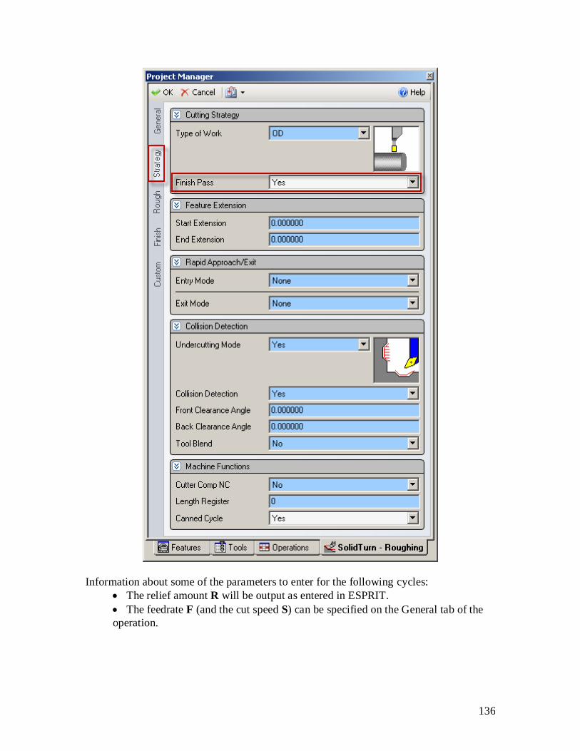
136
Information about some of the parameters to enter for the following cycles:
The relief amount R will be output as entered in ESPRIT.
The feedrate F (and the cut speed S) can be specified on the General tab of the
operation.

137
11.2.2. O.D./I.D. roughing
G71 U(1) R_ ;
G71 P_ Q_ U(2) W_ F_ ;
U(1) and W will be output as entered in ESPRIT. U(2)/2 will be multiplied by 2 to have
the correct value in the NC code U(2). R will be computed based on the entered

138
Maximum Depth of Cut and Retract % of Depth value: R = Maximum Depth of Cut *
Retract % of Depth / 100.
For example, if you set Maximum Depth of Cut to 5 and Retract % of Depth to 75, R
output in the NC code will be R3.75 (5*75/100).
Sample NC code with canned cycle: N5 (SPINDLE-1 ROUGH AND FINISH OD)
(T0303 TURNING INSERT OD 3V UPPER LEFT)
G28 U0
G28 V0 W0
G54
G00 T0303
M69
G99 G18 M46
G50 S5000
G97 S395 M03
G00 Y0.0 X125.0
Z1.888 M08
G96 S150
G71 U2.0 R2.0
G71 P6 Q7 U0.25 W0.125 F0.15
N6 G00 X95.777
G01 Z-0.112 F0.1
X100.0 Z-2.223
Z-20.0
X101.238
G03 X112.0 Z-25.381 I0.0 K-5.381 (R5.381)
N7 G01 Z-85.381
G96 S200
G70 P6 Q7
G97 S568
Z3.0
Sample NC code without canned cycle: N5 (SPINDLE-1 ROUGH AND FINISH OD)
(T0303 TURNING INSERT OD 3V UPPER LEFT)
G28 U0
G28 V0 W0
G54
G00 T0303
M69
G99 G18 M46
G50 S5000
G97 S395 M03
G00 Y0.0 X121.0
Z2.0 M08
G96 S150
G01 Z-85.381 F0.15
.
.
. X99.777
G01 X95.777

139
X100.0 Z-2.223 F0.1
Z-20.0
X101.238
G03 X112.0 Z-25.381 I0.0 K-5.381 (R5.381)
G01 Z-85.381
G00 Z3.0
G97 S568
11.2.3. Face roughing
G72 W(1) R_ ;
G72 P_ Q_ U_ W(2) F_ ;

140
W(1) and W(2) will be output as entered in ESPRIT. U/2 will be multiplied by 2 to have
the correct value in the NC code U. R will be computed based on the entered Maximum
Depth of Cut and Retract % of Depth value: R = Maximum Depth of Cut * Retract % of
Depth / 100.

141
11.3. Grooving cycle
11.3.1. Introduction
In ESPRIT, on the Strategy tab of the SolidTurn Grooving operation page, set Canned
Cycle to Yes to trigger the multiple repetitive cycle output.
Based on the selected work strategy (Type of Work), the output G-code will be different.
G74 will be output if you cut on the face of the part. G75 will be output if your profile is
on the O.D. or the I.D. of the part.

142
Information about some of the parameters to enter for the following cycles:
The return amount R(1) will be output as entered in ESPRIT.
P is an unsigned value, in radius. Q is an unsigned value. Specify P and Q in
mm, it will then be output in units of 0.001 mm without decimal point. For
example, if you enter 2 for P in ESPRIT, the output will be in the NC code P2000.
The feedrate F (and the cut speed S) can be specified on the General tab of the
operation.
Note that for face grooving, the value P designates the Step Over and the value
Q designates the Peck Increment. For O.D./I.D. grooving, these values are
REVERSED, i.e. P is the Peck Increment and Q is the Step Over.
Notes: Grooving canned cycles can only be used on grooves with straight wall geometry.
Grooves with a side taper angle must be programmed with a regular groove operation.

143
Grooving canned cycles can only be used when groove type is set to single plunge or
multiple plunge. If you set groove type to zigzag or zigzag diagonal, you will get the
following error message in your NC code: ERROR: SET GROOVE TYPE TO
SINGLE PLUNGE OR MULTIPLE PLUNGE FOR GROOVE CANNED CYCLE.
11.3.2. Face grooving
G74 R(1);
G74 X_ Z_ P_ Q_ F_ ;

144
11.3.3. O.D./I.D. grooving
G75 R(1) ;
G75 X_ Z_ P_ Q_ F_ ;

145
Sample NC code with canned cycle: N5 (SPINDLE-1 GROOVING OD)
(T0202 GROOVING INSERT OD UPPER LEFT)
G28 U0
G28 V0 W0
G54
G00 T0202
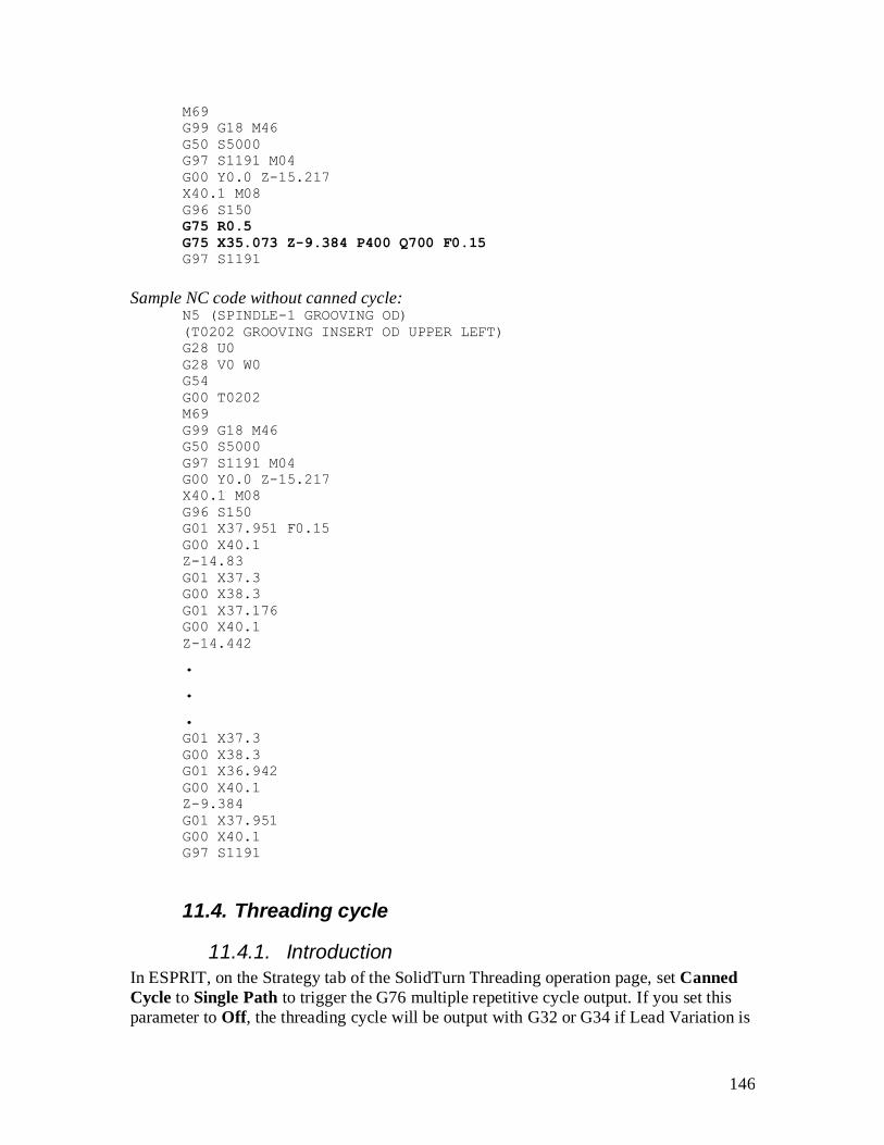
146
M69
G99 G18 M46
G50 S5000
G97 S1191 M04
G00 Y0.0 Z-15.217
X40.1 M08
G96 S150
G75 R0.5
G75 X35.073 Z-9.384 P400 Q700 F0.15
G97 S1191
Sample NC code without canned cycle: N5 (SPINDLE-1 GROOVING OD)
(T0202 GROOVING INSERT OD UPPER LEFT)
G28 U0
G28 V0 W0
G54
G00 T0202
M69
G99 G18 M46
G50 S5000
G97 S1191 M04
G00 Y0.0 Z-15.217
X40.1 M08
G96 S150
G01 X37.951 F0.15
G00 X40.1
Z-14.83
G01 X37.3
G00 X38.3
G01 X37.176
G00 X40.1
Z-14.442
.
.
. G01 X37.3
G00 X38.3
G01 X36.942
G00 X40.1
Z-9.384
G01 X37.951
G00 X40.1
G97 S1191
11.4. Threading cycle
11.4.1. Introduction
In ESPRIT, on the Strategy tab of the SolidTurn Threading operation page, set Canned
Cycle to Single Path to trigger the G76 multiple repetitive cycle output. If you set this
parameter to Off, the threading cycle will be output with G32 or G34 if Lead Variation is

147
different from 0. When Canned Cycle is set to Multiple Path, the threading cycle will be
output with G92.
Information about some of the parameters to enter for the following cycles:
The lead of the thread F will be output as entered in ESPRIT.
Specify the angle of shift of the thread cutting start angle Q in , it will then be
output in the units of 0.001without a decimal point. For example, if you enter 2
for Q in ESPRIT, the output will be in the NC code Q2000.
The cut speed S can be specified on the General tab of the operation.
On the Strategy tab, if you set the Lead-Out Type to Chamfer and the Chamfer Length
greater than 0, you will have M23 (chamfer ON) output prior to the G76 or G92
commands. With a different lead-out set, the M-code output will be M24 (chamfer OFF).

148
11.4.2. Threading with canned cycle set to single path
G76 P(1) Q(1) R(1) ;
G76 X_ Z_ R(2) P(2) Q(2) F_ ;

149

150
R(1) will be output as entered in ESPRIT. Q(1), P(2) and Q(2) are unsigned values, in
radius. Specify them in mm, they will then be output in units of 0.001 mm without
decimal point. For example, if you enter 2 for Q(1) in ESPRIT, the output will be in the
NC code Q2000.
Sample NC code: N5 (SPINDLE-1 SINGLE PATH)
(T0404 THREADING INSERT OD UPPER LEFT)
G28 U0
G28 V0 W0
G54
G00 T0404
M69
G99 G18 M46
G97 S500 M04
G00 Y0 Z0.847
X43.688 M08
M24
G76 P020560 Q300 R0.1
G76 X37.396 Z-9.737 P1146 Q400 F2.117

151
11.4.3. Threading with canned cycle set to off
Threading with canned cycle set to off, lead variation set to 0:
G32 X_ Z_ F_ Q_ ;
Sample NC code: N5 (SPINDLE-1 CANNED CYCLE OFF)
(T0404 THREADING INSERT OD UPPER LEFT)
G28 U0
G28 V0 W0

152
G54
G00 T0404
M69
G99 G18 M46
G97 S500 M04
G00 Y0 Z0.847
X43.688 M08
X38.888
G32 Z-9.737 F2.117 Q1000
G00 X43.688
Z0.847
X38.556
G32 Z-9.737 F2.117 Q1000
G00 X43.688
Z0.847
X38.302
G32 Z-9.737 F2.117 Q1000
G00 X43.688
Z0.847
X38.088
G32 Z-9.737 F2.117 Q1000
G00 X43.688
Z0.847
X37.899
G32 Z-9.737 F2.117 Q1000
G00 X43.688
Z0.847
X37.728
G32 Z-9.737 F2.117 Q1000
G00 X43.688
Z0.847
X37.571
G32 Z-9.737 F2.117 Q1000
G00 X43.688
Z0.847
X37.425
G32 Z-9.737 F2.117 Q1000
G00 X43.688
Z0.847
X37.396
G32 Z-9.737 F2.117 Q1000
G00 X43.688
Threading with canned cycle set to off, lead variation different from 0 (Option):
G34 X_ Z_ F_ K_ Q_ ;

153
K will be output as entered in ESPRIT.
Sample NC code: N5 (SPINDLE-1 CANNED CYCLE OFF)
(T0404 THREADING INSERT OD UPPER LEFT)
G28 U0
G28 V0 W0
G54
G00 T0404
M69
G99 G18 M46
G97 S500 M04
G00 Y0 Z0.847

154
X43.688 M08
X38.888
G34 Z-9.737 F2.117 K0.5 Q1000
G00 X43.688
Z0.847
X38.556
G34 Z-9.737 F2.117 K0.5 Q1000
G00 X43.688
Z0.847
X38.302
G34 Z-9.737 F2.117 K0.5 Q1000
G00 X43.688
Z0.847
X38.088
G34 Z-9.737 F2.117 K0.5 Q1000
G00 X43.688
Z0.847
X37.899
G34 Z-9.737 F2.117 K0.5 Q1000
G00 X43.688
Z0.847
X37.728
G34 Z-9.737 F2.117 K0.5 Q1000
G00 X43.688
Z0.847
X37.571
G34 Z-9.737 F2.117 K0.5 Q1000
G00 X43.688
Z0.847
X37.425
G34 Z-9.737 F2.117 K0.5 Q1000
G00 X43.688
Z0.847
X37.396
G34 Z-9.737 F2.117 K0.5 Q1000
G00 X43.688
11.4.4. Threading with canned cycle set to multiple path
The post processor will automatically adjust the output if you are cutting a straight or a
tapered thread.
Note: If you set the Lead-In Type to Feed or Chamfer or the Lead-Out Type to Feed, you
will get the following error message in your NC code: ERROR: WRONG LEAD-IN OR
LEAD-OUT TYPE SPECIFIED.

155
Straight thread cutting:
G92 X_ Z_ F_ Q_ ;
Sample NC code (straight thread): N5 (SPINDLE-1 CANNED CYCLE MULTIPLE PATH)
(T0404 THREADING INSERT OD UPPER LEFT)
G28 U0
G28 V0 W0
G54
G00 T0404
M69

156
G99 G18 M46
G97 S5000 M04
G00 Y0 Z0.0
X32.0 M08
M24
G92 X27.2 Z-30.0 F2.117 Q1000
X26.869
X26.614
X26.4
X26.211
X26.04
X25.883
X25.737
X25.709
G00 X32.0 Z0.0
Tapered thread cutting:
G92 X_ Z_ R_ F_ ;

157
Sample NC code (tapered thread): N5 (SPINDLE-1 CANNED MULTIPLE PATH)
(T0404 THREADING INSERT OD UPPER LEFT)
G28 U0
G28 V0 W0
G54
G00 T0404
M69
G99 G18 M46
G97 S5000 M04
G00 Y0 Z0.0
X44.0 M08
M24

158
G92 X39.2 Z-30.0 R-3.0 F2.117
X38.869
X38.614
X38.4
X38.211
X38.04
X37.883
X37.737
X37.709
G00 X44.0 Z0.0
12. Hole machining canned cycles and other
functionalities for drilling cycles
12.1. Introduction
Hole machining programs are so complicated, specified in several blocks. A hole
machining canned cycle, however, allows the hole machining to be programmed in one
block with the appropriate G codes below:
The Face Hole Machining Canned Cycle:
Hole machining is executed by the Z-axis with positioning executed by the combination
of the X-, C- and Y-axes (Y-axis specifications only).
The Side Hole Machining Canned Cycle:
Hole machining is executed by the X-axis with positioning executed by the combination
of the Z-, C- and Y-axes (Y-axis specifications only).
In ESPRIT, you can choose between the different drilling canned cycles using the Cycle
Type pull-down on the Drill tab for the SolidTurn Drilling cycle:

159
On the Drill tab for the SolidMillTurn Drilling cycle:
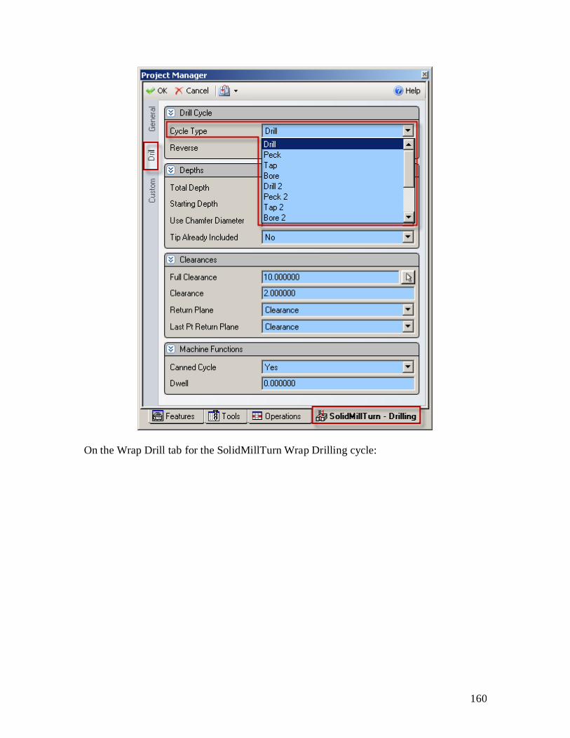
160
On the Wrap Drill tab for the SolidMillTurn Wrap Drilling cycle:
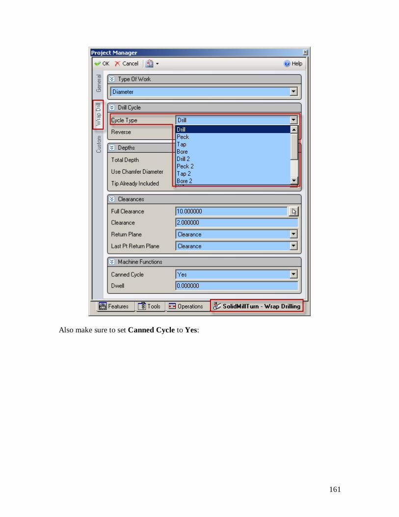
161
Also make sure to set Canned Cycle to Yes:
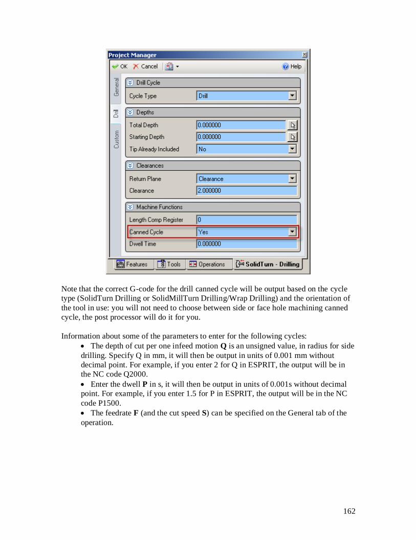
162
Note that the correct G-code for the drill canned cycle will be output based on the cycle
type (SolidTurn Drilling or SolidMillTurn Drilling/Wrap Drilling) and the orientation of
the tool in use: you will not need to choose between side or face hole machining canned
cycle, the post processor will do it for you.
Information about some of the parameters to enter for the following cycles:
The depth of cut per one infeed motion Q is an unsigned value, in radius for side
drilling. Specify Q in mm, it will then be output in units of 0.001 mm without
decimal point. For example, if you enter 2 for Q in ESPRIT, the output will be in
the NC code Q2000.
Enter the dwell P in s, it will then be output in units of 0.001s without decimal
point. For example, if you enter 1.5 for P in ESPRIT, the output will be in the NC
code P1500.
The feedrate F (and the cut speed S) can be specified on the General tab of the
operation.

163
12.2. Face and side high-speed deep hole drilling / Face and side deep hole drilling / Deep hole drilling with G74
12.2.1. Face and side high-speed deep hole drilling (G83.5/G87.5)
CAUTION !!! Use SolidMillTurn Drilling or SolidMillTurn Wrap Drilling
G83.5 X_ (Y_) C_ Z_ R_ Q_ P_ F_ ;
G87.5 Z_ (Y_) C_ X_ R_ Q_ P_ F_ ;

164
12.2.2. Face and side deep hole drilling (G83.6/G87.6)
CAUTION !!! Use SolidTurn Drilling, SolidMillTurn Drilling or SolidMillTurn
Wrap Drilling
G83.6 X_ (Y_) C_ Z_ R_ Q_ P_ F_ ;
G87.6 Z_ (Y_) C_ X_ R_ Q_ P_ F_ ;
Settings for SolidTurn Drilling:
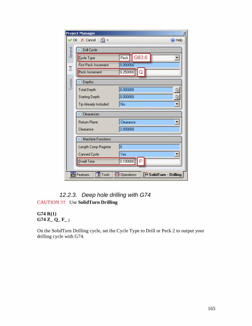
165
12.2.3. Deep hole drilling with G74
CAUTION !!! Use SolidTurn Drilling
G74 R(1)
G74 Z_ Q_ F_ ;
On the SolidTurn Drilling cycle, set the Cycle Type to Drill or Peck 2 to output your
drilling cycle with G74.

166
If you select Drill, the depth of cut per one infeed motion Q will be set to the total depth
of cut plus 5 mm (or plus 0.2 in) so the hole will be drilled in one infeed motion.
If you select Peck 2, you will be able to specify the value of Q that will be output in the
NC code:
R(1) corresponds to return amount. It will be output as entered in ESPRIT when Peck 2 is
selected. R0.0 will be output when Drill is selected.

167
12.3. Face and side spot drilling (G83/G87)
CAUTION !!! Use SolidMillTurn Drilling or SolidMillTurn Wrap Drilling
G83 X_ (Y_) C_ Z_ R_ P_ F_ ;
G87 Z_ (Y_) C_ X_ R_ P_ F_ ;

168
12.4. Face and side tapping / Tapping at center of spindle
12.4.1. Face and side tapping (G84/G88)
CAUTION !!! Use SolidMillTurn Drilling or SolidMillTurn Wrap Drilling
G84 X_ (Y_) C_ Z_ R_ P_ F_ ;
G88 Z_ (Y_) C_ X_ R_ P_ F_ ;

169
12.4.2. Tapping at center of spindle (G32)
CAUTION !!! Use SolidTurn Drilling
G32 Z_ F_ ;
If you set the Cycle Type to Tap on the SolidTurn Drilling cycle, the tapping canned
cycle will be output with G32.

170
Sample NC code with G32 output: N5 (SPINDLE-1 TAPPING AT CENTER OF SPINDLE)
(T0707 27MM INSERT DRILL UPPER LEFT)
G28 U0
G28 V0 W0
G54
G00 T0707
M69
G99 G18 M46
G97 S500 M03
G00 Y0.0 Z2.0
X0.0 M08
G32 Z-2.0 F0.15
M05
Z2.0 M04
Note: The direction of the tap is controlled by the tool spindle direction (clockwise or
counterclockwise) set on the tool page.

171
12.5. Face and side synchronized tapping / Face and side (high-speed) deep hole synchronized tapping / Spindle synchronized tapping
12.5.1. Restriction of synchronized tapping
CAUTION !!! During the synchronized tapping cycle, the maximum speeds for the
rotary tool is 3000 min-1
.
If the maximum speed for the rotary tool holder is less than the above, specify a speed
that is less than the maximum speed for the holder.
12.5.2. Face and side synchronized tapping (M329 G84/M329 G88)
CAUTION !!! Use SolidMillTurn Drilling or SolidMillTurn Wrap Drilling
M329 S_ ;
G84 X_ (Y_) C_ Z_ R_ P_ F_ ;
M329 S_ ;
G88 Z_ (Y_) C_ X_ R_ P_ F_ ;

172

173
12.5.3. Face and side (high-speed) deep hole synchronized tapping (M329 G84/M329 G88)
CAUTION !!! Use SolidMillTurn Drilling or SolidMillTurn Wrap Drilling
M329 S_ ;
G84 X_ (Y_) C_ Z_ R_ P_ Q_ F_ ;
M329 S_ ;
G88 Z_ (Y_) C_ X_ R_ P_ Q_ F_ ;

174

175
You can enter the depth of cut per pass Q in the Custom Setting 3 field of the SolidMill
Drilling (or Wrap Drilling) operation.

176
With Custom Settings utility (MoriSeiki AddIn loaded):
12.5.4. Spindle synchronized tapping (M329 G84) (Option)
CAUTION !!! Use SolidTurn Drilling

177
M329 S_ ;
G84 X_ Z_ R_ P_ F_ ;
The M329 G84 command is used to execute a tapping operation at the center of the
spindle (rotational center of workpiece).
This tapping cycle allows the Z-axis feed to be always synchronized with spindle
revolution.
If you set the Cycle Type to Tap 2 on the SolidTurn Drilling cycle, the synchronized
tapping canned cycle will be output with M329 G84.

178
12.6. Face and side boring / Boring in turning mode
12.6.1. Face and side boring (G85/G89)
CAUTION !!! Use SolidMillTurn Drilling or SolidMillTurn Wrap Drilling
G85 X_ (Y_) C_ Z_ R_ P_ F_ ;
G89 Z_ (Y_) C_ X_ R_ P_ F_ ;

179
12.6.2. Boring in turning mode
CAUTION !!! Use SolidTurn Drilling
If you want to perform a boring cycle with the SolidTurn Drilling operation, set the Cycle
Type to Bore and Canned Cycle to No. No canned cycle is supported for the turn boring
cycle. The code will be output with linear G01 moves.

180
Note: If you omit to set Canned Cycle to No, you will get the following error message in
your NC code: ERROR: CANNED CYCLE NOT SUPPORTED FOR LATHE
BORING CYCLE.
12.7. Spindle / Rotary Tool Spindle Simultaneous Operation Mode
CAUTION !!! Use SolidTurn Drilling
M90 S_ ;
M91;
M290 S_ ;
M291;
The M90 and M290 commands are used to rotate the spindle and the rotary tool
simultaneously to machine a hole at the center of the spindle (workpiece) at a proper
cutting speed if necessary cutting speed cannot be obtained by rotating only the spindle or
the rotary tool.

181
On the Custom tab of the SolidTurn Drilling operation, set the Custom Setting 6 to 90 to
trigger the output of the M90 (or M290 if machining on the spindle 2 side) command.
On the General tab, set in Speed RPM the desired total speed, which mean speed of the
turning spindle plus speed of the rotary tool.
You can then specify with the Custom Setting 7 the percentage of the total speed you
want to apply to the rotary tool.
Example:
If you set the Speed RPM to 6000 and Custom Setting 7 to 30, the spindle speed will be
6000 - 30% * 6000 = 4200 rpm and the rotary tool speed will be 6000 * 30% = 1800 rpm.
With Custom Settings utility (MoriSeiki AddIn loaded):

182
Notes:
Set on the General tab, the Feed Unit to Per Minute: You can determine the
feedrate of the tool assuming the spindle speed of 6000 min−1
, which is the sum of
the turning spindle speed (4200 min-1
) and the rotary tool speed (1800 min−1
).
On the General tab, make sure to change the Maximum RPM value according
to the specified Speed RPM value. If Speed RPM is set to 6000 rpm but Maximum
RPM to 5000 rpm, the output will be computed using 5000 rpm, as a safety.
The direction of rotation has to be specified on the Tool page by the pull-down
Spindle Direction.

183
Sample NC code: N5 (SPINDLE-1 DRILL)
(T0606 DRILL)
G28 U0
G28 V0 W0
G54
G00 T0606
M69
G98 G18 M46
M05
G97
M90 S1800
G97 S4200 M03
G00 Y0.0 Z4.0

184
X0.0 M08
G74 R0.0
G74 Z-10.0 Q19000 F600.0
M05
M91
13. 3D coordinate conversion (G68.1) (Option)
13.1. Introduction
T0;
G68.1 X0 Y0 Z0 I0 J1 K0 R_ ;
T_ ;
T0;
G69.1;
By using the G68.1 command, it is possible to execute coordinate conversion for the
program shape, created in the 3D coordinate system, around an optional axis.
The 3D coordinate conversion function is effective when machining with an angle holder.
By using the program created assuming that machining is executed on the ZX plane, the
programmed machining can be executed on the plane after rotation by converting the
coordinate system by specifying the center of rotation, the direction of the center axis of
rotation, and the angle of rotation.
Note that the center of rotation will always be (X0; Y0; Z0) and the direction of the
center axis of rotation (I0; J1; K0): the coordinate system will be tilted around the Y-axis.
The angle of rotation R_ will automatically be computed for you based on the angle of
the tilted holder.
13.2. How to output 3D coordinate conversion
In ESPRIT, do a right click on the Features tab of the project manager and click on New
Work Coordinate.
On the Work Coordinate window:
Enter the Work Coordinate Name (for spindle 1 side: G54_Tilted and for spindle
2 side G55_Tilted, for example).
Enter the Standard Work Coordinate Number: Usually 54 for spindle 1 side and
55 for spindle 2 side.
Set the Work Plane to YZX if you machine on the spindle 1 side and to G55 if
you machine on the spindle 2 side.
Set Rotate With Part to Point Only.

185
Make sure to activate the work coordinate in which you want to output your tilted
operation (G54_Tilted for spindle 1 side or G55_Tilted for spindle 2 side).
Your work coordinate is now correctly set for 3D coordinate conversion. If you create a
Tilted tool in ESPRIT, the NC code output when using this tool will be with 3D
coordinate conversion.

186
If, for example, you program a SolidMillTurn Drilling operation using a tilted tool in the
defined G54_Tilted work coordinate, the 3D coordinate conversion will be output in the
NC code.
Note: If you programmed an operation with a tilted tool but forgot to set Rotate With Part
to Point Only for your work coordinate, you will get the following error message in your
NC code: ERROR: ROTATE WITH PART MUST BE SET TO POINT ONLY FOR
3D COORDINATE CONVERSION.
CAUTION !!! When working with G68.1 function, make sure to set Autorun Mode to
NONE in Turning Work Coordinates add-in.

187
Sample NC code of a tilted drilling operation on the spindle 1 side: N5 (SPINDLE-1 TILTED DRILLING)
(T0909 TILTED DRILL 1MM UPPER LEFT)
G28 U0
G28 V0 W0
G54
G00 T0909
M69
G98 G17 M45
G28 H0
G97 S3000 M13
G00 C0.0
M68
G00 Z15.224
X68.547 Y0.0
T0
G68.1 X0.0 Y0.0 Z0.0 I0 J1 K0 R45.0
G00 T0909
G00 Z35.0
X26.941 Y0.0 M08
G83.6 Z7.572 R-20.428 Q500 P1000 F150.0
G80
M09
T0
G69.1

188
14. 4-axis wrap milling cycles with interpolation
14.1. Introduction
The NC code can be very long for wrap milling operations using the C-axis. But it can be
shorten by turning on the interpolation.
14.2. Cylindrical interpolation
The cylindrical interpolation can be turned on the SolidMillTurn Wrap Pocketing and
Wrap Contouring pages.
On the Wrap tab of the operation pages, set Cylindrical Interpolation to Yes to output 4-
axis wrap milling operations with cylindrical interpolation.
It will be turned on in the NC code by G07.1 C_ and turned off by G07.1 C0.
C corresponds to the radius of the workpiece (groove bottom). It can be specified (as a
diameter value) on the Wrap tab in the Working Diameter field of the operation pages:

189
Cylindrical interpolation is used when cutting on cylinder circumference. Programming is
made assuming a plane by developing the cylinder circumference into the plane.
Using cylindrical interpolation can shorten the program length because ESPRIT outputs
the circular motions in the cylindrical plane.
Without cylindrical interpolation, circular motions in the cylindrical plane are
approximated by small linear moves (quality varies with the tolerance of the operation
page).
Sample NC code with cylindrical interpolation on: N5 (SPINDLE-1 WRAP MILLING - RADIAL WALL)
(T1212 EM 09.0 UPPER LEFT)
G28 U0
G28 V0 W0
G54
G00 T1212

190
M69
G98 G19 M45
G28 H0
G97 S3000 M13
G00 C-5.994
G00 Z-20.0
X150.0 Y0.0 M08
G01 G19 W0 H0
G07.1 C12.5
G01 X116.0 Z-20.0 C-5.994 F5000.0
X90.0 F600.0
C-14.27
Z-80.045 C-14.268 F480.0
G03 Z-80.5 C-13.661 R0.501
G01 Z-80.493 C73.732
G03 Z-79.998 C74.27 R0.503
G01 Z-19.955 C74.268
G03 Z-19.5 C73.661 R0.501
G01 Z-19.507 C-13.729
G03 Z-19.817 C-14.226 R0.509
Z-20.0 C-14.27 R0.501
G01 Z-20.001 C-5.994
X116.0 F600.0
X150.0 Z-20.001 C-5.994 F5000.0
G07.1 C0.0
14.3. Polar coordinate interpolation (Notching)
The polar coordinate interpolation can be turned on the SolidMillTurn Wrap Face
Pocketing and Wrap Face Contouring pages.
On the Strategy tab of the operation pages, set Polar Interpolation to Yes to output rotary
face milling operations with polar interpolation.

191
It will be turned on in the NC code by G112 and turned off by G113.
Tool positions are output in rectangular coordinate system (X; C) (C = Y distance),
instead of XC (C in degrees). The work system rotates to the start C position of the
operation. The start point is always at C (Y distance) = 0.

192
Sample NC code with polar interpolation on: N5 (SPINDLE-1 ROTARY FACE MILLING)
(T1010 6MM EM UPPER LEFT)
G28 U0
G28 V0 W0
G54
G00 T1010
M69
G98 G17 M45
G28 H0
G97 S3000 M13
G00 C-44.112
G00 Z1.0

193
X67.58 Y0.0 M08
M69
G112
G01 X67.58 C0.0 Z1.0 F5000.0
Z-28.297 F5000.0
G41 X57.962 C1.369 F600.0
X47.833 C-16.425
G02 X46.881 C-17.391 I-2.885 J0.821 (R3.0)
X33.313 C-23.968 I-23.44 J17.391 (R29.187)
G40 G01 X42.843 C-30.825
Z1.0 F5000.0
G113
15. Custom Settings index
15.1. On operation pages
See page Use Comments
Custom Setting 1
61 Head 1 & 2: Park turret with G53 Head 1 & 2: Used for Park cycle
119 Head 2: Workpiece pushing check (G38) Head 2: Used for Part pickup cycle
50 Head 1 & 2: Output of rapid moves (G00) with linear interpolation moves (G01 F)
Head 1 & 2: Used for all milling cycles
Custom Setting 2
65 Head 1 & 2: Output stop coolant code (M09) Head 1 & 2: Used for Park cycle
119 Head 2: B-axis retraction stroke Head 2: Used for Part pickup cycle / Goes
with Custom Setting 1
Custom Setting 3
173 Head 1 & 2: Depth of cut per pass Q Head 1 & 2: Used for SolidMillTurn Drilling
cycle (TAP2)
119 Head 2: B-axis feedrate Head 2: Used for Part pickup cycle / Goes
with Custom Setting 1
Custom Setting 4
91 Head 1: X position of bar stopper tool (G53) Head 1: Used for Barfeed (By stopper) cycle
119 Head 2: Tolerance for workpiece transfer
position
Head 2: Used for Part pickup cycle / Goes
with Custom Setting 1
Custom Setting 5
91 Head 1: Z position of bar stopper tool (G53) Head 1: Used for Barfeed (By stopper) cycle
119 Head 2: B-axis feedrate changing position Head 2: Used for Part pickup cycle / Goes
with Custom Setting 1
Custom Setting 6
180 Head 1 & 2: Spindle/Rotary Tool Spindle Simultaneous Operation Mode
Head 1 & 2: Used for SolidTurn Drilling cycle
107 Head 1 & 2: C-Axis mode for spindle orientation
Head 1 & 2: Used for Part pickup cycle
Custom Setting 7 180
Head 1 & 2: Percentage of the total speed you
want to apply to the rotary tool
Head 1 & 2: Used for SolidTurn Drilling cycle
/ Goes with Custom Setting 6
107 Head 1 & 2: C-Axis angle value Head 1 & 2: Used for Part pickup cycle
Custom Setting 8 80 Head 2: Spindle 2 catching position Head 2: Used for Part release cycle
Custom Setting 9 80 Head 2: Type of workpiece ejector Head 2: Used for Part release cycle
Custom Setting 10 Not used
15.2. On tool pages
See page Use Comments

194
Custom Setting 1 54 Second coolant type Used to set a second coolant (Optional)
Custom Setting 2 Not used
Custom Setting 3 35 Second home position Used to use second home position (G30)
Custom Setting 4 Not used
Custom Setting 5 Not used
Custom Setting 6 58 Special coolant ON Used to turn on special coolant (Optional)
Custom Setting 7 58 Special coolant OFF Used to turn off special coolant (Optional) /
Goes with Custom Setting 6
Custom Setting 8 31 Tool life management Used to turn on/off tool life management
Custom Setting 9 Not used
Custom Setting 10 Not used
15.3. In machine setup
See page Use Comments
Custom Setting 1 14 Output of Program End (M02), Program End
and Rewind (M30) or Sub-Program End (M99)
Custom Setting 2 15 Work unloader on spindle 2 side: hand or
receiver
Custom Setting 3 Not used
Custom Setting 4 16 Tool station for part transfer and work
unloader (Turret 1)
Custom Setting 5 16 Tool station for part transfer and work unloader (Turret 2)
Custom Setting 6 Not used
Custom Setting 7 17 C-axis brake clamp/unclamp
Custom Setting 8
Not used
Custom Setting 9 16 C-axis roll over
Custom Setting 10 21 Set position of optional stop code (M01) in the NC code
Custom String 9 22
Output of the end of bar macro call (/2 M98 Pxxxx); Custom String 9 should be set to the
program number (xxxx) called by M98
Custom String 10 23 99, 133 or 200 Tool wear offset number (Option)
Custom String 10 24 Set position of sequence numbers (N)