Embed Size (px)
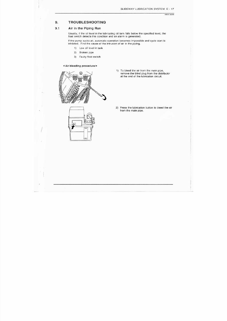
DESCRIPTION
MANUAL DE MANTENIMIENTO GENERAL PARA CENTROS DE MAQUINADO MORISEIKI,
Citation preview

7/21/2019 MORISEIKI MAINTENANCE CLASS
http://slidepdf.com/reader/full/moriseiki-maintenance-class 1/409
J & H Machine Tools, Inc.4345 Morris Park Drive
Charlotte, NC 28227
Service DepartmentTelephone: 704-545-7056
Fax: 800-892-1862
Mori Seiki
Maintenance Class
Presented by
Lewis Craven
7/21/2019 MORISEIKI MAINTENANCE CLASS
http://slidepdf.com/reader/full/moriseiki-maintenance-class 2/409
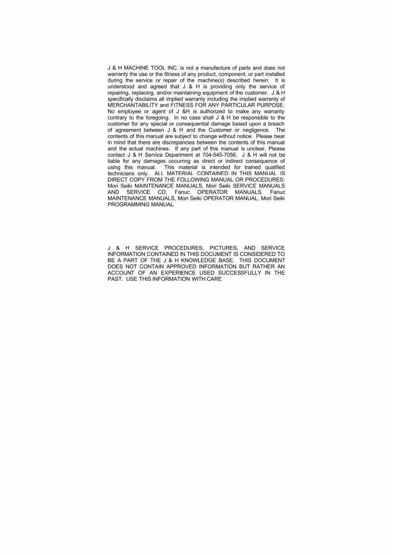
J & H MACHINE TOOL INC. is not a manufacture of parts and does notwarranty the use or the fitness of any product, component, or part installedduring the service or repair of the machine(s) described herein. It isunderstood and agreed that J & H is providing only the service ofrepairing, replacing, and/or maintaining equipment of the customer. J & Hspecifically disclaims all implied warranty including the implied warranty ofMERCHANTABILITY and FITNESS FOR ANY PARTICULAR PURPOSE.No employee or agent of J &H is authorized to make any warrantycontrary to the foregoing. In no case shall J & H be responsible to thecustomer for any special or consequential damage based upon a breachof agreement between J & H and the Customer or negligence. The
contents of this manual are subject to change without notice. Please bearin mind that there are discrepancies between the contents of this manualand the actual machines. If any part of this manual is unclear, Pleasecontact J & H Service Department at 704-545-7056. J & H will not beliable for any damages occurring as direct or indirect consequence ofusing this manual. This material is intended for trained qualifiedtechnicians only. ALL MATERIAL CONTAINED IN THIS MANUAL ISDIRECT COPY FROM THE FOLLOWING MANUAL OR PROCEDURES:Mori Seiki MAINTENANCE MANUALS, Mori Seiki SERVICE MANUALS
AND SERVICE CD, Fanuc OPERATOR MANUALS, FanucMAINTENANCE MANUALS, Mori Seiki OPERATOR MANUAL, Mori Seiki
PROGRAMMING MANUAL.
J & H SERVICE PROCEDURES, PICTURES, AND SERVICEINFORMATION CONTAINED IN THIS DOCUMENT IS CONSIDERED TOBE A PART OF THE J & H KNOWLEDGE BASE. THIS DOCUMENTDOES NOT CONTAIN APPROVED INFORMATION BUT RATHER AN
ACCOUNT OF AN EXPERIENCE USED SUCCESSFULLY IN THEPAST. USE THIS INFORMATION WITH CARE
7/21/2019 MORISEIKI MAINTENANCE CLASS
http://slidepdf.com/reader/full/moriseiki-maintenance-class 3/409
7/21/2019 MORISEIKI MAINTENANCE CLASS
http://slidepdf.com/reader/full/moriseiki-maintenance-class 4/409
7/21/2019 MORISEIKI MAINTENANCE CLASS
http://slidepdf.com/reader/full/moriseiki-maintenance-class 5/409
7/21/2019 MORISEIKI MAINTENANCE CLASS
http://slidepdf.com/reader/full/moriseiki-maintenance-class 6/409

7/21/2019 MORISEIKI MAINTENANCE CLASS
http://slidepdf.com/reader/full/moriseiki-maintenance-class 7/409
7/21/2019 MORISEIKI MAINTENANCE CLASS
http://slidepdf.com/reader/full/moriseiki-maintenance-class 8/409
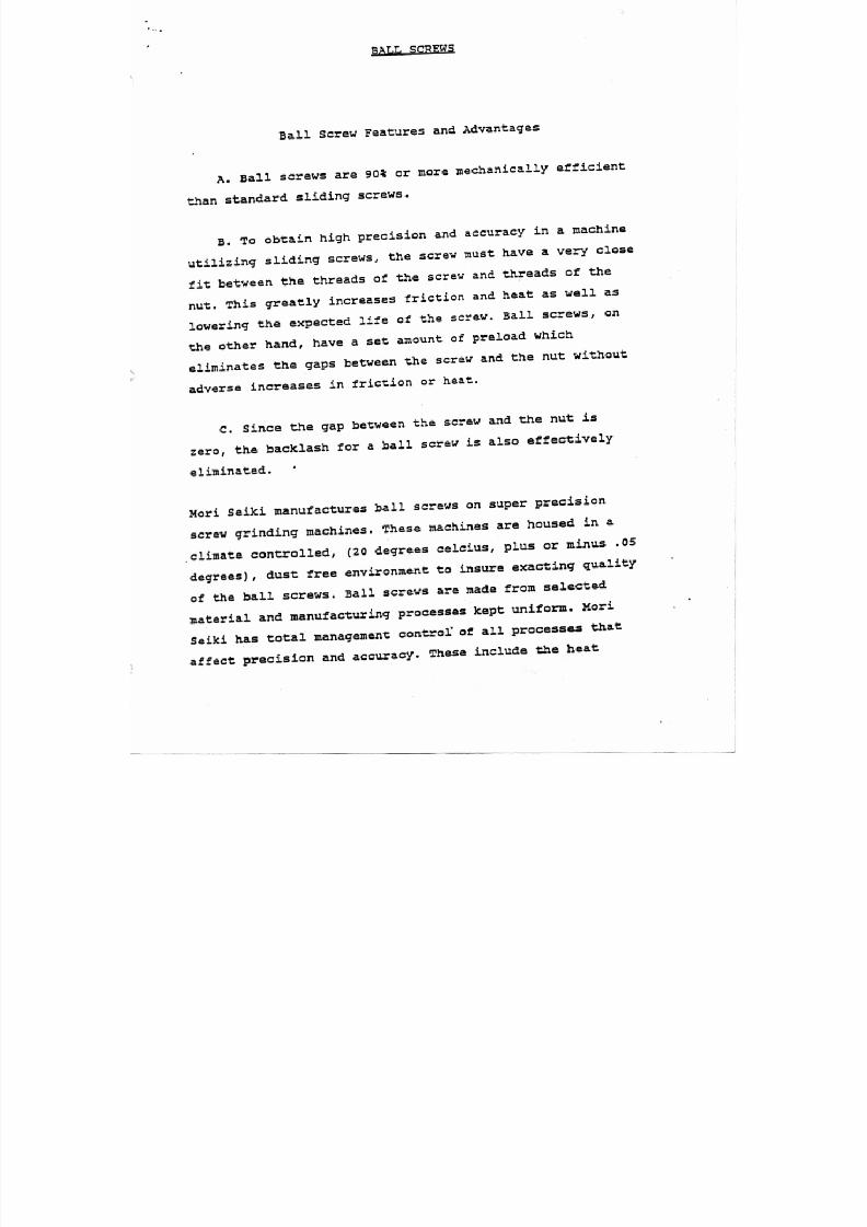
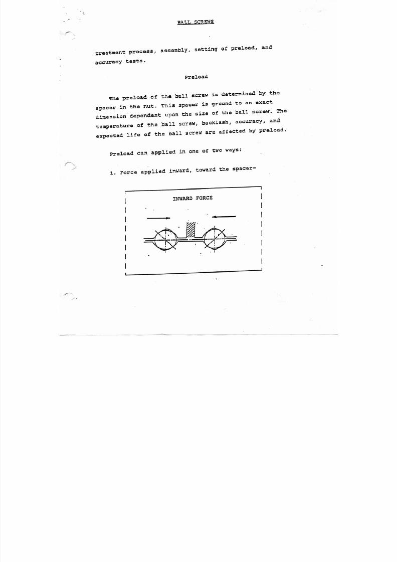
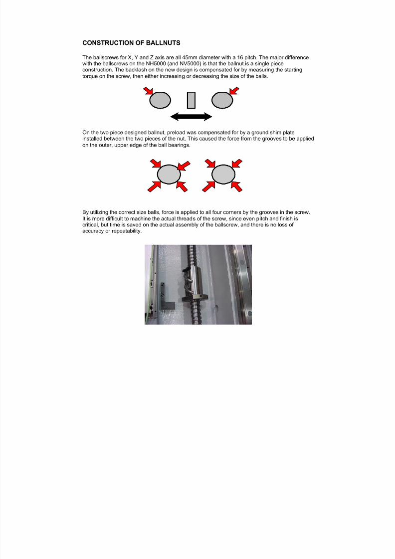
CONSTRUCTION OF BALLNUTS
The ballscrews for X, Y and Z axis are all 45mm diameter with a 16 pitch. The major differencewith the ballscrews on the NH5000 (and NV5000) is that the ballnut is a single piece
construction. The backlash on the new design is compensated for by measuring the startingtorque on the screw, then either increasing or decreasing the size of the balls.
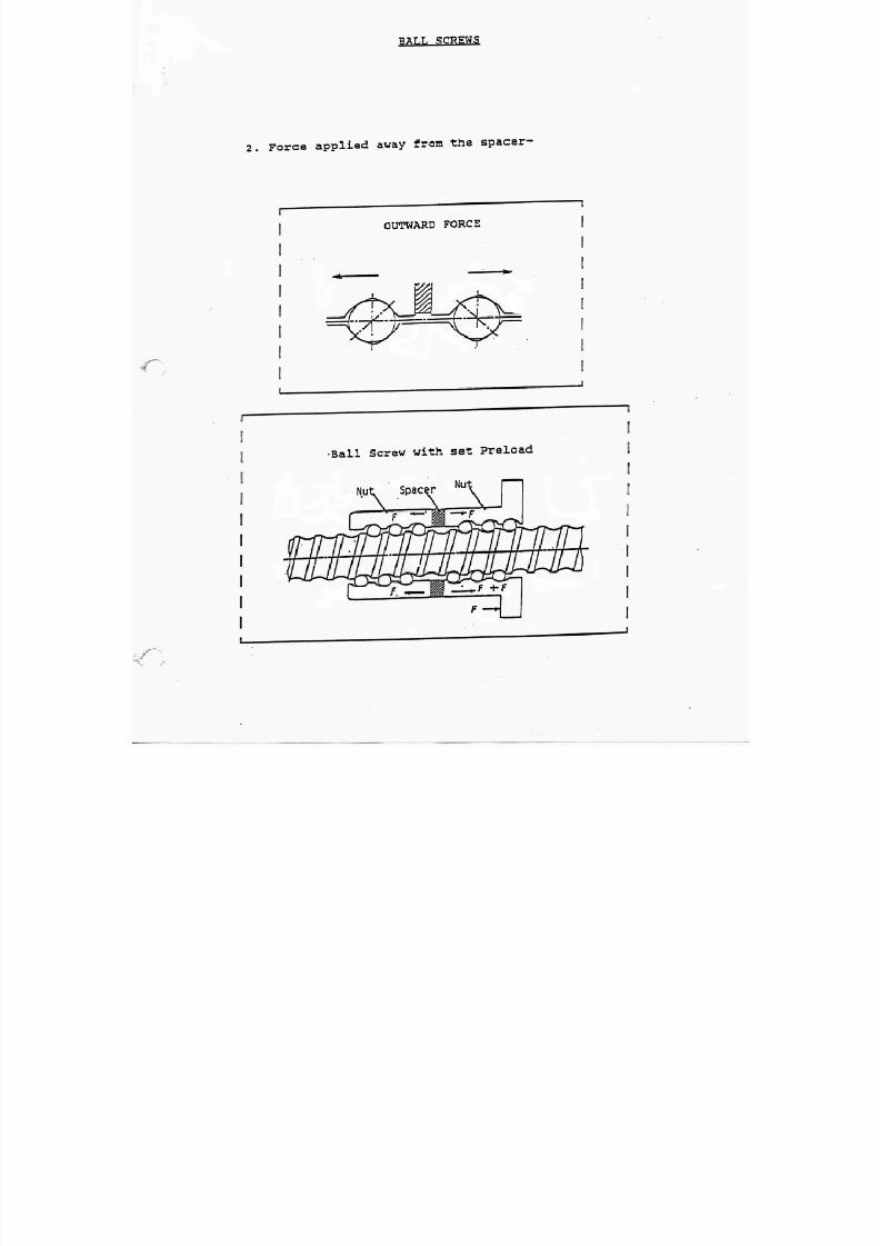
On the two piece designed ballnut, preload was compensated for by a ground shim plate
installed between the two pieces of the nut. This caused the force from the grooves to be appliedon the outer, upper edge of the ball bearings.
By utilizing the correct size balls, force is applied to all four corners by the grooves in the screw.It is more difficult to machine the actual threads of the screw, since even pitch and finish iscritical, but time is saved on the actual assembly of the ballscrew, and there is no loss of accuracy or repeatability.
7/21/2019 MORISEIKI MAINTENANCE CLASS
http://slidepdf.com/reader/full/moriseiki-maintenance-class 9/409
7/21/2019 MORISEIKI MAINTENANCE CLASS
http://slidepdf.com/reader/full/moriseiki-maintenance-class 10/409
7/21/2019 MORISEIKI MAINTENANCE CLASS
http://slidepdf.com/reader/full/moriseiki-maintenance-class 11/409
7/21/2019 MORISEIKI MAINTENANCE CLASS
http://slidepdf.com/reader/full/moriseiki-maintenance-class 12/409
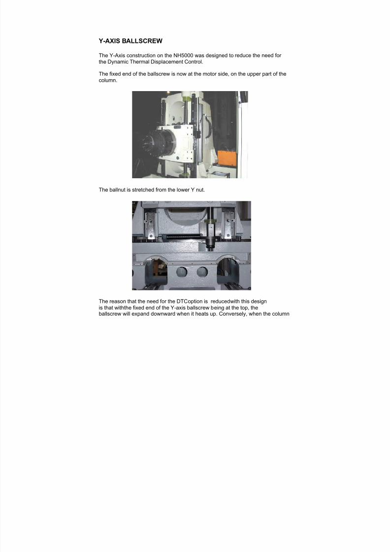
Y-AXIS BALLSCREW
The Y-Axis construction on the NH5000 was designed to reduce the need for
the Dynamic Thermal Displacement Control.
The fixed end of the ballscrew is now at the motor side, on the upper part of thecolumn.
The ballnut is stretched from the lower Y nut.
The reason that the need for the DTC option is reduced with this designis that with the fixed end of the Y-axis ballscrew being at the top, theballscrew will expand downward when it heats up. Conversely, when the column

7/21/2019 MORISEIKI MAINTENANCE CLASS
http://slidepdf.com/reader/full/moriseiki-maintenance-class 13/409
heats up, it will expand upward. Since the fixed end of the ballscrew is located along way from the X-axis linear guide (where the column rests), the ballscrew candevelop up to 3 times as much heat as the column and not show the effects of thermalexpansion.
7/21/2019 MORISEIKI MAINTENANCE CLASS
http://slidepdf.com/reader/full/moriseiki-maintenance-class 14/409
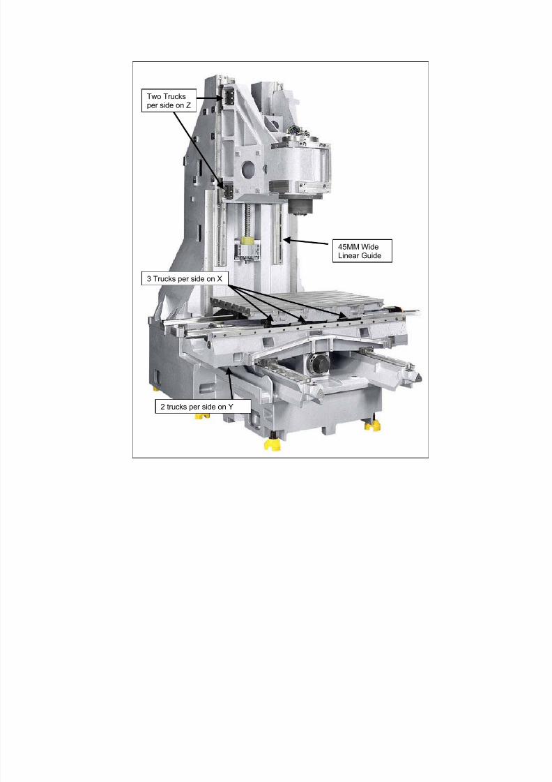
45MM WideLinear Guide
Two Trucksper side on Z
3 Trucks per side on X
2 trucks per side on Y
7/21/2019 MORISEIKI MAINTENANCE CLASS
http://slidepdf.com/reader/full/moriseiki-maintenance-class 15/409
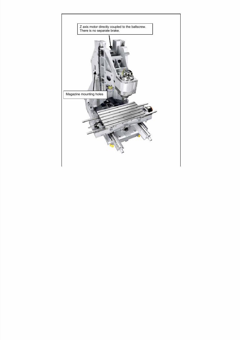
Z axis motor directly coupled to the ballscrew.There is no separate brake.
Magazine mounting holes
7/21/2019 MORISEIKI MAINTENANCE CLASS
http://slidepdf.com/reader/full/moriseiki-maintenance-class 16/409
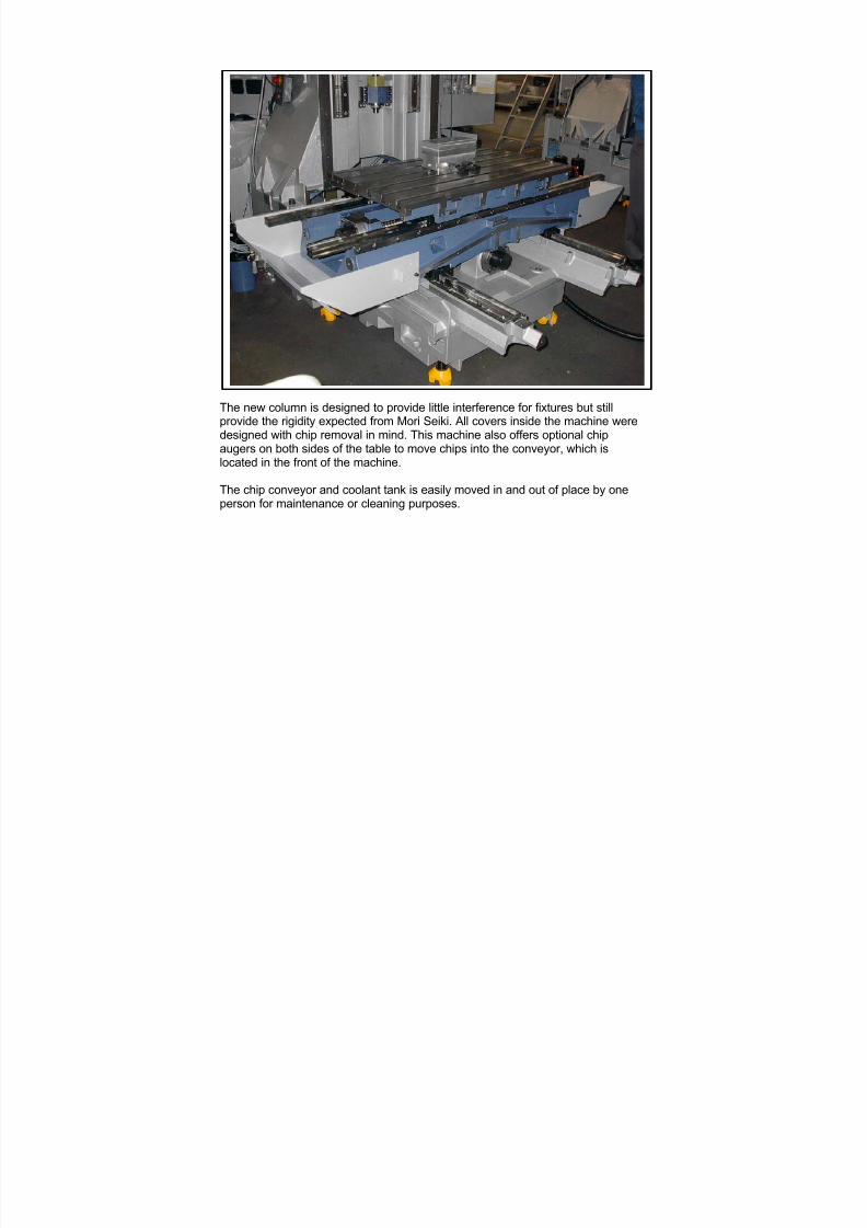
The new column is designed to provide little interference for fixtures but stillprovide the rigidity expected from Mori Seiki. All covers inside the machine weredesigned with chip removal in mind. This machine also offers optional chipaugers on both sides of the table to move chips into the conveyor, which islocated in the front of the machine.
The chip conveyor and coolant tank is easily moved in and out of place by oneperson for maintenance or cleaning purposes.
7/21/2019 MORISEIKI MAINTENANCE CLASS
http://slidepdf.com/reader/full/moriseiki-maintenance-class 17/409
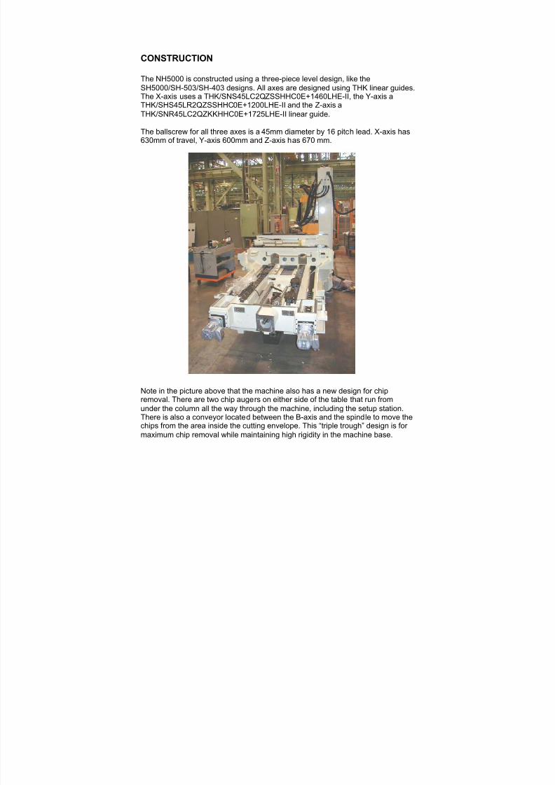
CONSTRUCTION
The NH5000 is constructed using a three-piece level design, like theSH5000/SH-503/SH-403 designs. All axes are designed using THK linear guides.
The X-axis uses a THK/SNS45LC2QZSSHHC0E+1460LHE-II, the Y-axis aTHK/SHS45LR2QZSSHHC0E+1200LHE-II and the Z-axis aTHK/SNR45LC2QZKKHHC0E+1725LHE-II linear guide.
The ballscrew for all three axes is a 45mm diameter by 16 pitch lead. X-axis has630mm of travel, Y-axis 600mm and Z-axis has 670 mm.
Note in the picture above that the machine also has a new design for chipremoval. There are two chip augers on either side of the table that run fromunder the column all the way through the machine, including the setup station.There is also a conveyor located between the B-axis and the spindle to move thechips from the area inside the cutting envelope. This “triple trough” design is for maximum chip removal while maintaining high rigidity in the machine base.

7/21/2019 MORISEIKI MAINTENANCE CLASS
http://slidepdf.com/reader/full/moriseiki-maintenance-class 18/409
The ways for each axis are covered with a new type sliding cover. The material islike a spring steel, so anything dropped on it will not dent. It is also designed toflex when chips get under the sliding seals instead of building up and separatingthe covers as in the past.
The X/Y cover, when installed or when being replaced, must be indicated in toensure flatness. It is adjustable by loosening the screws on the slotted mountingbrackets, adjusting the position, then tightening the bolts back. In the picturebelow, you can see the pantographic support of the X and Y axis.
X Axis Cover Y Axis Cover
7/21/2019 MORISEIKI MAINTENANCE CLASS
http://slidepdf.com/reader/full/moriseiki-maintenance-class 19/409
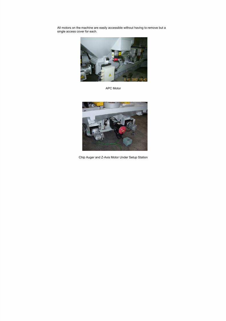
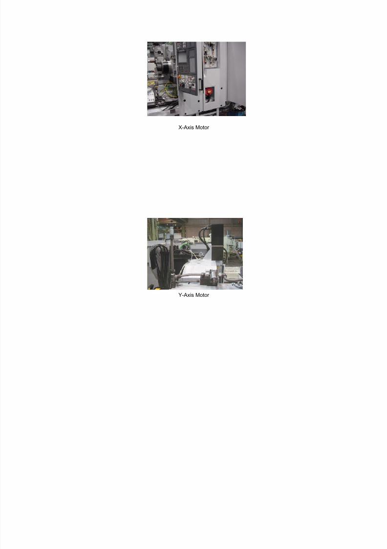
All motors on the machine are easily accessible without having to remove but asingle access cover for each.
APC Motor
Chip Auger and Z-Axis Motor Under Setup Station

7/21/2019 MORISEIKI MAINTENANCE CLASS
http://slidepdf.com/reader/full/moriseiki-maintenance-class 20/409
B-Axis Motor and Belt Drive
Magazine Motor and ATC Motor
7/21/2019 MORISEIKI MAINTENANCE CLASS
http://slidepdf.com/reader/full/moriseiki-maintenance-class 21/409
X-Axis Motor
Y-Axis Motor

7/21/2019 MORISEIKI MAINTENANCE CLASS
http://slidepdf.com/reader/full/moriseiki-maintenance-class 22/409
Conveyor Motor

7/21/2019 MORISEIKI MAINTENANCE CLASS
http://slidepdf.com/reader/full/moriseiki-maintenance-class 23/409
ATC
FULL 4TH AXIS TABLE
SPINDLE + BALLNUT + APC AND 1 DEGREE INDEXER
AIR PANEL
SPINDLE
ELECTRICAL CABINET
EXTERNAL CHIP CONVEYOR
MAGAZINE
COOLANT TANK
COOLANT PUMPS
OIL COOLER
HYDRAULIC TANK
SSEMBLY IDENTIFICATION
7/21/2019 MORISEIKI MAINTENANCE CLASS
http://slidepdf.com/reader/full/moriseiki-maintenance-class 24/409
7/21/2019 MORISEIKI MAINTENANCE CLASS
http://slidepdf.com/reader/full/moriseiki-maintenance-class 25/409
7/21/2019 MORISEIKI MAINTENANCE CLASS
http://slidepdf.com/reader/full/moriseiki-maintenance-class 26/409

7/21/2019 MORISEIKI MAINTENANCE CLASS
http://slidepdf.com/reader/full/moriseiki-maintenance-class 27/409
7/21/2019 MORISEIKI MAINTENANCE CLASS
http://slidepdf.com/reader/full/moriseiki-maintenance-class 28/409
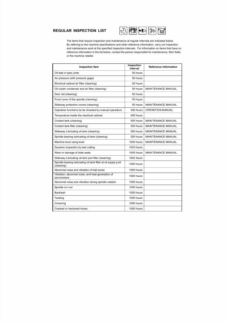
REGULAR INSPECTION LIST
The items that require inspection and maintenance at regular intervals are indicated below.By referring to the machine specifications and other reference information, carry out inspection
and maintenance work at the specified inspection intervals. For information on items that have no
reference information in the list below, contact the person responsible for maintenance, Mori Seiki,
or the machine retailer.
Inspection ItemInspection
IntervalReference Information
Oil leak in pipe joints 50 hours
Air pressure (with pressure gage) 50 hoursElectrical cabinet air filter (cleaning) 50 hours
Oil cooler condenser and air filter (cleaning) 50 hours MAINTENANCE MANUAL
Door rail (cleaning) 50 hours
Front cover of the spindle (cleaning) 50 hours
Slideway protection covers (cleaning) 50 hours MAINTENANCE MANUAL
Operation functions (to be checked by manual operation) 500 hours OPERATION MANUAL
Temperature inside the electrical cabinet 500 hours
Coolant tank (cleaning) 500 hours MAINTENANCE MANUAL
Coolant tank filter (cleaning) 500 hours MAINTENANCE MANUAL
Slideway lubricating oil tank (cleaning) 500 hours MAINTENANCE MANUAL
Spindle bearing lubricating oil tank (cleaning) 500 hours MAINTENANCE MANUAL
Machine level using level 1000 hours MAINTENANCE MANUAL
Dynamic inspection by test cutting 1000 hours
Wear or damage of slide seals 1000 hours MAINTENANCE MANUAL
Slideway lubricating oil tank port filter (cleaning) 1000 hoursSpindle bearing lubricating oil tank filter at oil supply port(cleaning)
1000 hours
Abnormal noise and vibration of ball screw 1000 hours
Vibration, abnormal noise, and heat generation ofservomotors
1000 hours
Abnormal noise and vibration during spindle rotation 1000 hours
Spindle run-out 1000 hours
Backlash 1000 hours
Twisting 1000 hoursCrowning 1000 hours
7/21/2019 MORISEIKI MAINTENANCE CLASS
http://slidepdf.com/reader/full/moriseiki-maintenance-class 29/409
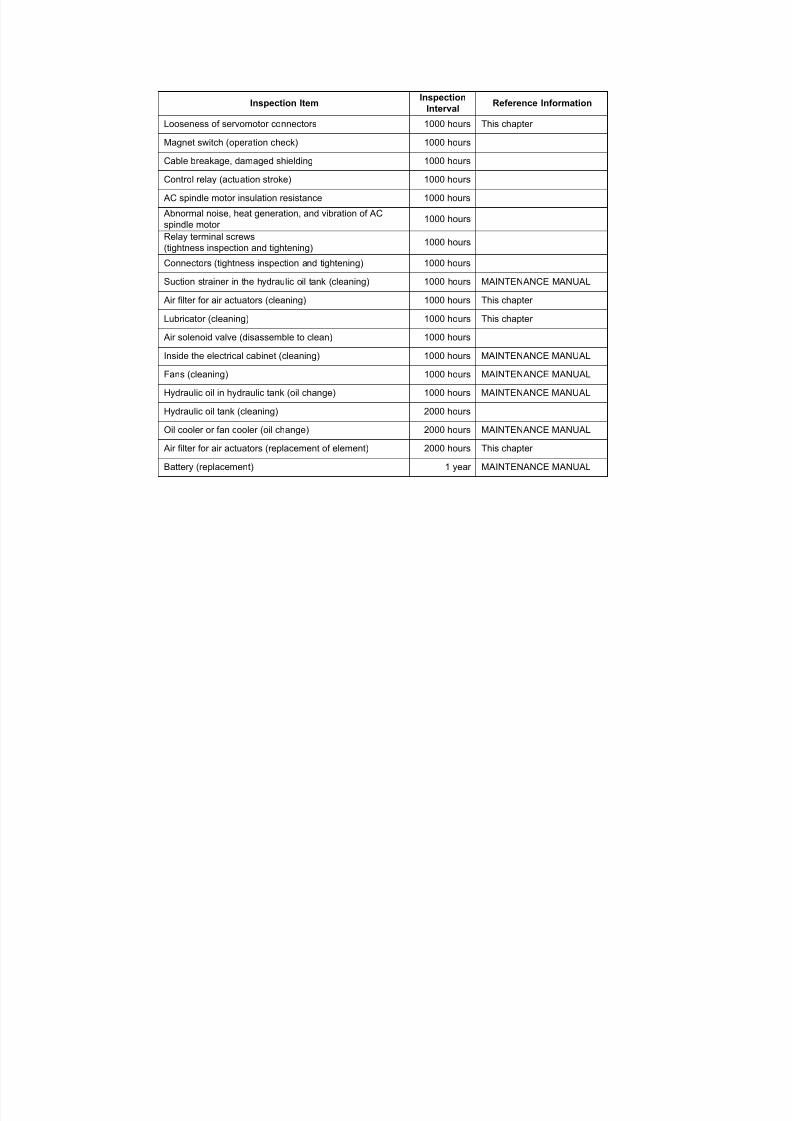
Looseness of servomotor connectors 1000 hours This chapter
Magnet switch (operation check) 1000 hours
Cable breakage, damaged shielding 1000 hours
Control relay (actuation stroke) 1000 hours
AC spindle motor insulation resistance 1000 hours
Abnormal noise, heat generation, and vibration of ACspindle motor
1000 hours
Relay terminal screws(tightness inspection and tightening)
1000 hours
Connectors (tightness inspection and tightening) 1000 hours
Suction strainer in the hydraulic oil tank (cleaning) 1000 hours MAINTENANCE MANUAL
Air filter for air actuators (cleaning) 1000 hours This chapter
Lubricator (cleaning) 1000 hours This chapter
Air solenoid valve (disassemble to clean) 1000 hours
Inside the electrical cabinet (cleaning) 1000 hours MAINTENANCE MANUAL
Fans (cleaning) 1000 hours MAINTENANCE MANUAL
Hydraulic oil in hydraulic tank (oil change) 1000 hours MAINTENANCE MANUAL
Hydraulic oil tank (cleaning) 2000 hoursOil cooler or fan cooler (oil change) 2000 hours MAINTENANCE MANUAL
Air filter for air actuators (replacement of element) 2000 hours This chapter
Battery (replacement) 1 year MAINTENANCE MANUAL
Inspection ItemInspection
IntervalReference Information

7/21/2019 MORISEIKI MAINTENANCE CLASS
http://slidepdf.com/reader/full/moriseiki-maintenance-class 30/409
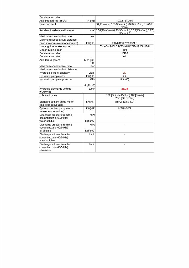
OILING CHARTS
Oil Point Oil Type QuantityOil Change
Interval
Replenishing
Interval
1 Hydraulic unit tankDaphneHydraulic Fluid 32
20 L
Check oillevel gageEvery 1000
hours ofoperation
—
2 Oil cooler tankDaphneSuper Multi 2M
38 LEvery 2000
hours ofoperation
—
3 Coolant tank — 540 L As required Replenish asrequired
4
Spindle bearing/ballscrews/APC unitlubricating oil tank(oil-air lubrication)
DaphneMechanic Oil 32
2 L —Check oil level gage
Replenish asrequired
Table lubricating oiltank (1-degree indextable)
DaphneMechanic Oil 32
2 L —When carrying outdisassembly and
adjustment
5Table lubricating oiltank (full 4th-axisrotary table)
Tonna Oil S68 2 L —Check oil level gage
Replenish asrequired
6 ATC unit Spirax HD 80W-90 20 L — Replenish asrequired
1
2
3
45
6

7/21/2019 MORISEIKI MAINTENANCE CLASS
http://slidepdf.com/reader/full/moriseiki-maintenance-class 31/409
(1) The oil indicated in the table above is used when the machine is delivered.
For equivalent oil, refer to "Oil Recommendations".
(2) For the oil handling method, refer to the MATERIAL SAFETY DATA SHEET providedby the oil manufacturer.
NOTE
7/21/2019 MORISEIKI MAINTENANCE CLASS
http://slidepdf.com/reader/full/moriseiki-maintenance-class 32/409
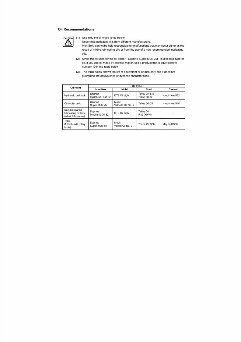
Oil Recommendations
(1) Use only the oil types listed below.
Never mix lubricating oils from different manufacturers.Mori Seiki cannot be held responsible for malfunctions that may occur either as the
result of mixing lubricating oils or from the use of a non-recommended lubricating
oils.
(2) Since the oil used for the oil cooler - Daphne Super Multi 2M - is a special type of
oil, if you use oil made by another maker, use a product that is equivalent to
number 10 in the table below.
(3) The table below shows the list of equivalent oil names only and it does not
guarantee the equivalence of dynamic characteristics.
Oil PointOil Type
Idemitsu Mobil Shell Castrol
Hydraulic unit tankDaphneHydraulic Fluid 32
DTE Oil LightTellus Oil S32Tellus Oil 32
Hyspin AWS32
Oil cooler tankDaphneSuper Multi 2M
MobilVelocite Oil No. 6
Tellus Oil C5 Hyspin AWS10
Spindle bearinglubricating oil tank(oil-air lubrication)
DaphneMechanic Oil 32
DTE Oil LightTellus OilR32 (XHVI)
—
Table(full 4th-axis rotary
table)
Daphne
Super Multi 68
Mobil
Vactra Oil No. 2
Tonna Oil S68 Magna BD68
CAUTION
7/21/2019 MORISEIKI MAINTENANCE CLASS
http://slidepdf.com/reader/full/moriseiki-maintenance-class 33/409
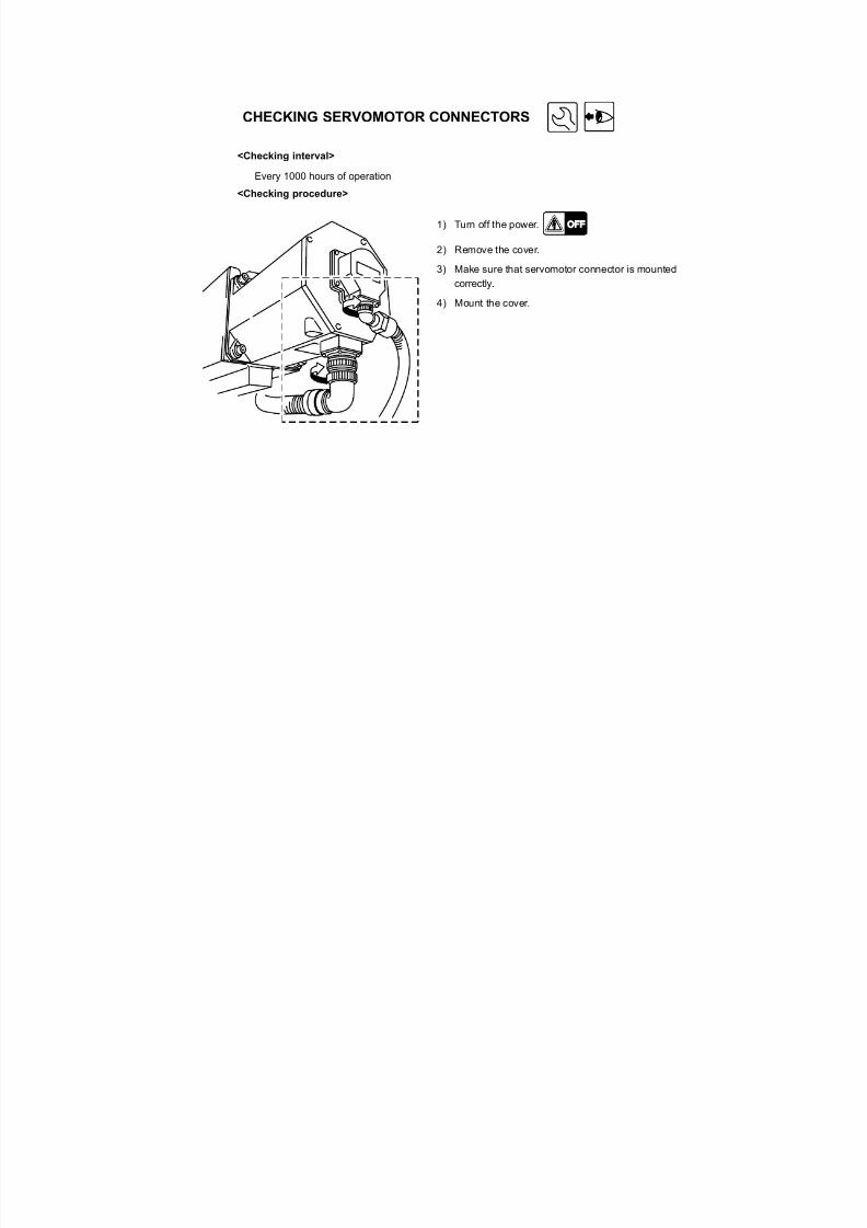
CHECKING SERVOMOTOR CONNECTORS
<Checking interval>
Every 1000 hours of operation
<Checking procedure>
1) Turn off the power.
2) Remove the cover.
3) Make sure that servomotor connector is mounted
correctly.
4) Mount the cover.
7/21/2019 MORISEIKI MAINTENANCE CLASS
http://slidepdf.com/reader/full/moriseiki-maintenance-class 34/409
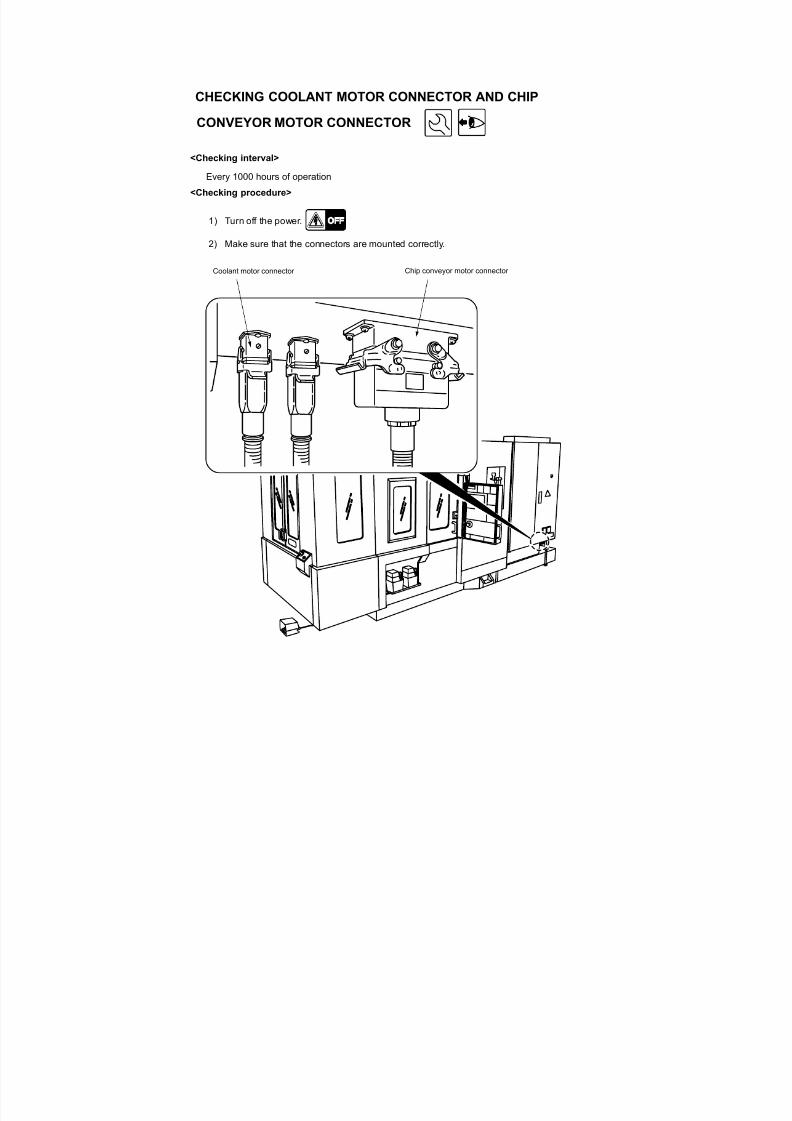
CHECKING COOLANT MOTOR CONNECTOR AND CHIP
CONVEYOR MOTOR CONNECTOR
<Checking interval>
Every 1000 hours of operation
<Checking procedure>
1) Turn off the power.
2) Make sure that the connectors are mounted correctly.
Coolant motor connector Chip conveyor motor connector
7/21/2019 MORISEIKI MAINTENANCE CLASS
http://slidepdf.com/reader/full/moriseiki-maintenance-class 35/409
CLEANING THE AIR FILTER
If the air filter element is clogged, the pressure of the air supplied to the actuators is decreased,causing their operation failure. Therefore, the air filter element should be cleaned at regular
intervals or the element should be replaced if it is heavily clogged.
The air filter is equipped with a float type automatic discharge unit.
Usually, the drain is automatically discharged through the discharge port.
However, if the drain is not automatically discharged or if foreign matter has accumulated at the
bottom bowl, operate the drain cock manually to discharge the drain.
Manual Discharge of the Drain
<Cleaning interval>
When the accumulation is not discharged automatically, or when foreign matter has accumulated
at the bottom of bowl
<Procedure>
Turn the manually operated drain cock at the bottom of the air filter counterclockwise to discharge
the drain.
7/21/2019 MORISEIKI MAINTENANCE CLASS
http://slidepdf.com/reader/full/moriseiki-maintenance-class 36/409
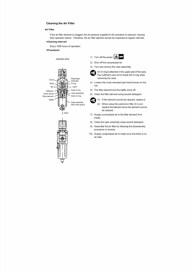
Cleaning the Air Filter
Air Filter
If the air filter element is clogged, the air pressure supplied to the actuators is reduced, causing
their operation failure. Therefore, the air filter element should be inspected at regular intervals.
<Cleaning interval>
Every 1000 hours of operation
<Procedure>
1) Turn off the power.
2) Shut off the compressed air.
3) Turn and remove the case assembly.
An O-ring is attached in the upper part of the case.
Pay sufficient care not to break the O-ring while
removing the case.
4) Loosen the cross-recessed pan head screws on the
rod.
5) The filter element and the baffle come off.
6) Clean the filter element using neutral detergent.
(1) If the element cannot be cleaned, replace it.(2) When using the submicron filter (0.3 m),
replace the element since the element cannot
be cleaned.
7) Supply compressed air to the filter element from
inside.
8) Clean the case assembly using neutral detergent.
9) Assemble the air filter by following the disassembly
procedure in reverse.
10) Supply compressed air to make sure that there is noair leak.
AW3000-4000
Drain
Valve assembly
Case O-ring
OUT
O-ring
Case assembly(with case guard)
Cover Diaphragmassembly
Deflector
Valve spring
Filter element
IN
Body
Baffle
OUT
Valve O-ring
NOTE
NOTE
7/21/2019 MORISEIKI MAINTENANCE CLASS
http://slidepdf.com/reader/full/moriseiki-maintenance-class 37/409
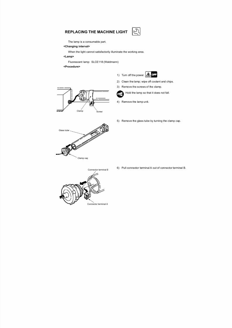
REPLACING THE MACHINE LIGHT
The lamp is a consumable part.
<Changing interval>
When the light cannot satisfactorily illuminate the working area.
<Lamp>
Fluorescent lamp: SLCE118 (Waldmann)
<Procedure>
1) Turn off the power.
2) Clean the lamp; wipe off coolant and chips.
3) Remove the screws of the clamp.
Hold the lamp so that it does not fall.
4) Remove the lamp unit.
5) Remove the glass tube by turning the clamp cap.
6) Pull connector terminal A out of connector terminal B.
Clamp Screw
NOTE
Glass tube
Clamp cap
Connector terminal A
Connector terminal B
7/21/2019 MORISEIKI MAINTENANCE CLASS
http://slidepdf.com/reader/full/moriseiki-maintenance-class 38/409
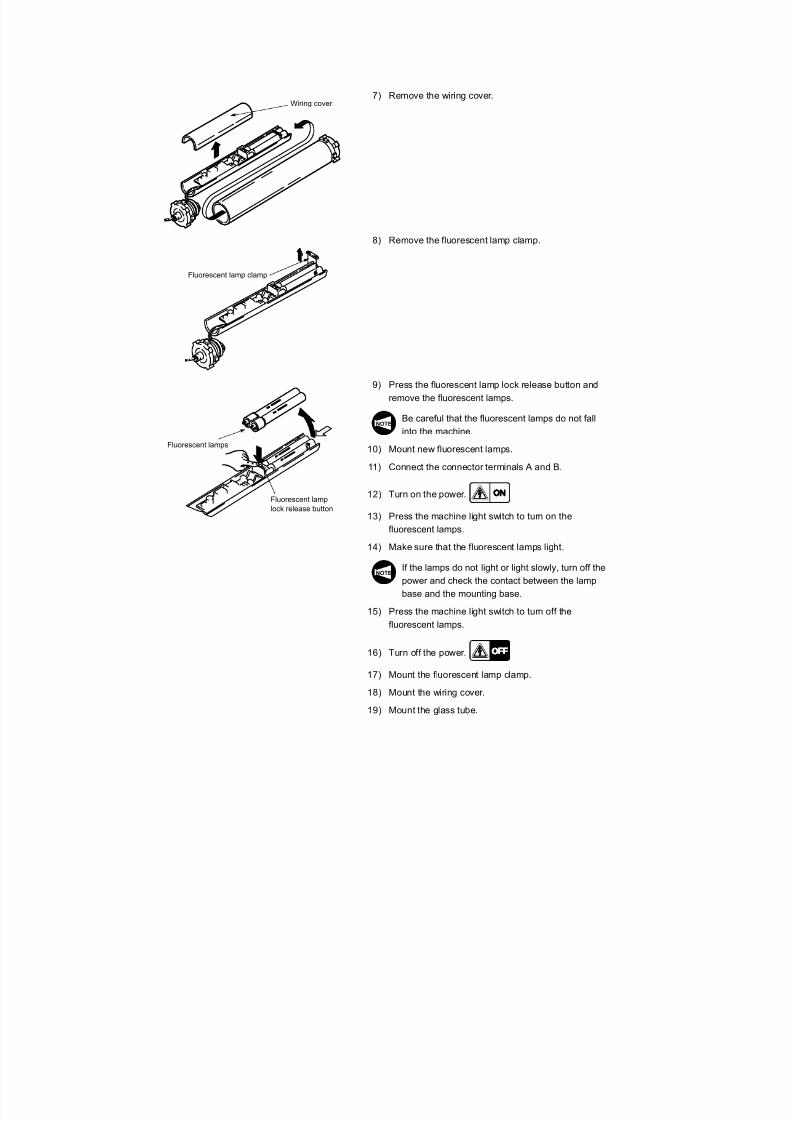
7) Remove the wiring cover.
8) Remove the fluorescent lamp clamp.
9) Press the fluorescent lamp lock release button and
remove the fluorescent lamps.
Be careful that the fluorescent lamps do not fallinto the machine.
10) Mount new fluorescent lamps.
11) Connect the connector terminals A and B.
12) Turn on the power.
13) Press the machine light switch to turn on the
fluorescent lamps.
14) Make sure that the fluorescent lamps light.
If the lamps do not light or light slowly, turn off the
power and check the contact between the lamp
base and the mounting base.
15) Press the machine light switch to turn off the
fluorescent lamps.
16) Turn off the power.
17) Mount the fluorescent lamp clamp.
18) Mount the wiring cover.19) Mount the glass tube.
Wiring cover
Fluorescent lamp clamp
Fluorescent lamps
Fluorescent lamplock release button
NOTE
NOTE

7/21/2019 MORISEIKI MAINTENANCE CLASS
http://slidepdf.com/reader/full/moriseiki-maintenance-class 39/409
20) Tighten the clamp cap.
When tightening the clamp cap, insert a tool such
as a screwdriver into each of the holes machined
in the parts, indicated by (1) and (2) in thediagram, and secure it tightly. Make sure that O-
rings are properly fitted before tightening the
clamp cap.
If the O-rings are loose, coolant or other
foreign matter may get into the fluorescent
lamp unit.
21) Mount the lamp unit on the clamp.
(1)
(2)
O-ring
NOTE
CAUTION

7/21/2019 MORISEIKI MAINTENANCE CLASS
http://slidepdf.com/reader/full/moriseiki-maintenance-class 40/409
X-axis travel(Longitudinal movement of column)
630
Y-axis travel(Vertical movement of spindle head)
600
Z-axis travel(Cross movement of table)
670
Distance from table surface tospindle center
50~650
Distance from table center to spindlegage plane
100~800
Table working surface 500×500Table loading capacity kg (lb.) 500Maximum workpiece swing diameter ö730Maximum workpiece height 900Table surface configuration M16 24 100 mmMinimum table indexing angle ° 1 (0.001)Table indexing time sec 2.0 [90°]Spindle speed range*2 min-1 14000 (20000)
Number of spindle speed ranges 1Max. spindle torque N - m (ft/lbf) 221
1.4(14,000)Type of spindle taper hole 7/24 No. 40
Spindle bearing inner diameter 65Rapid traverse rate mm/min (ipm) 500000.54(X),0.44(Y),0.58(Z)
feedrate mm/min (ipm) 0~50000Jog feedrate mm/min (ipm) 0~1260 [15]Type of tool shank MAS BT-40 (CAT-40)Type of retention knob 90°Tool storage capacity 30, 40, 60, 120, 180Maximum tool diameter (with adjacent tools)
80
Maximum tool diameter (without adjacent tools) 180
Maximum tool length 400Maximum tool mass kg (lb.) 8 (12)Maximum moment (from gage line) 7.84(14.13)
N-m (ft/lbf)Method of tool selection 30 or 40
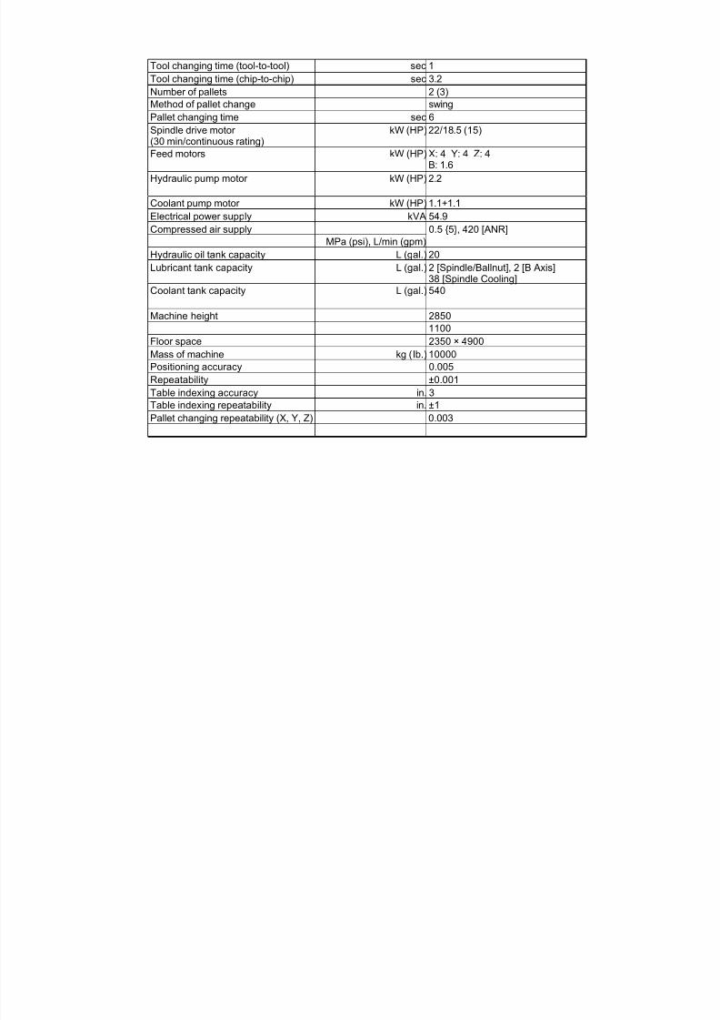
SPECIFICATIONS
7/21/2019 MORISEIKI MAINTENANCE CLASS
http://slidepdf.com/reader/full/moriseiki-maintenance-class 41/409
7/21/2019 MORISEIKI MAINTENANCE CLASS
http://slidepdf.com/reader/full/moriseiki-maintenance-class 42/409
7/21/2019 MORISEIKI MAINTENANCE CLASS
http://slidepdf.com/reader/full/moriseiki-maintenance-class 43/409

7/21/2019 MORISEIKI MAINTENANCE CLASS
http://slidepdf.com/reader/full/moriseiki-maintenance-class 44/409
Mesh size of coolant tank 30 16
Coolant filtration accuracyrequirementsat through spindle coolant spindlesystem specification
ì m 20
Positioning accuracy 0.005
Repeatability of positioning ±0.001
7/21/2019 MORISEIKI MAINTENANCE CLASS
http://slidepdf.com/reader/full/moriseiki-maintenance-class 45/409
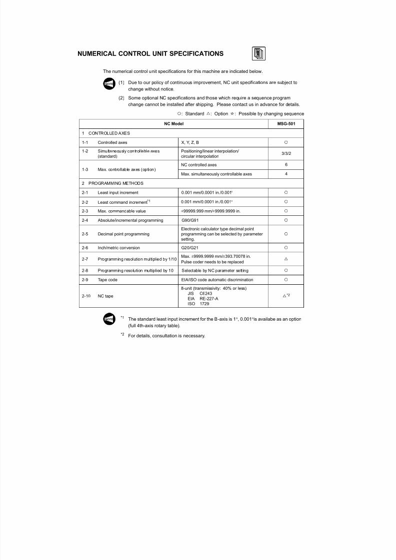
NUMERICAL CONTROL UNIT SPECIFICATIONS
The numerical control unit specifications for this machine are indicated below.
(1) Due to our policy of continuous improvement, NC unit specifications are subject to
change without notice.
(2) Some optional NC specifications and those which require a sequence program
change cannot be installed after shipping. Please contact us in advance for details.
: Standard : Option : Possible by changing sequence
*1 The standard least input increment for the B-axis is 1, 0.001 is availabe as an option
(full 4th-axis rotary table).
*2 For details, consultation is necessary.
NC Model MSG-501
1 CONTROLLED AXES
1-1 Controlled axes X, Y, Z, B
1-2 Simultaneously controllable axes(standard)
Positioning/linear interpolation/circular interpolation
3/3/2
1-3 Max. controllable axes (option)NC controlled axes 6
Max. simultaneously controllable axes 4
2 PROGRAMMING METHODS
2-1 Least input increment 0.001 mm/0.0001 in./0.001
2-2 Least command increment*1 0.001 mm/0.0001 in./0.001
2-3 Max. commandable value 99999.999 mm/9999.9999 in.
2-4 Absolute/incremental programming G90/G91
2-5 Decimal point programmingElectronic calculator type decimal pointprogramming can be selected by parametersetting.
2-6 Inch/metric conversion G20/G21
2-7 Programming resolution multiplied by 1/10Max. 9999.9999 mm/393.70078 in.Pulse coder needs to be replaced
2-8 Programming resolution multiplied by 10 Selectable by NC parameter setting
2-9 Tape code EIA/ISO code automatic discrimination
2-10 NC tape
8-unit (transmissivity: 40% or less)JIS C6243EIA RE-227-AISO 1729
*2
NOTE
NOTE
7/21/2019 MORISEIKI MAINTENANCE CLASS
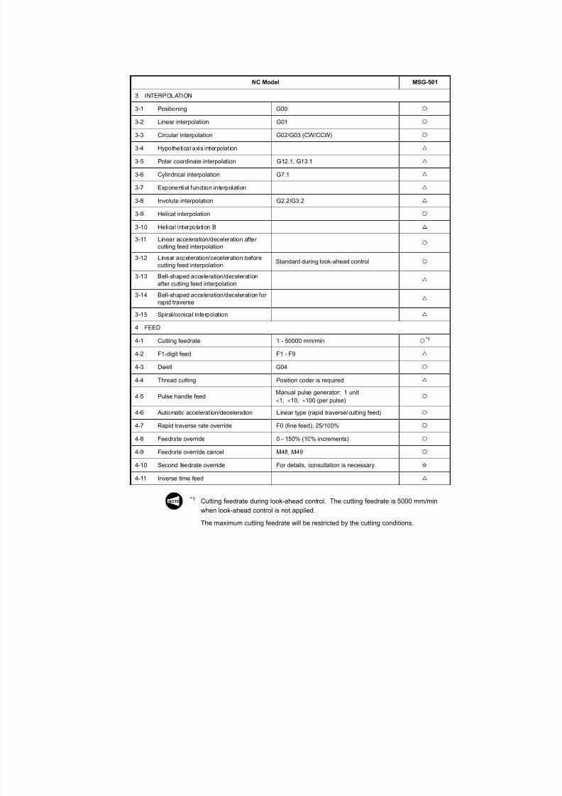
http://slidepdf.com/reader/full/moriseiki-maintenance-class 46/409*1 Cutting feedrate during look-ahead control. The cutting feedrate is 5000 mm/min
when look ahead control is not applied
NC Model MSG-501
3 INTERPOLATION3-1 Positioning G00
3-2 Linear interpolation G01
3-3 Circular interpolation G02/G03 (CW/CCW)
3-4 Hypothetical axis interpolation
3-5 Polar coordinate interpolation G12.1, G13.1
3-6 Cylindrical interpolation G7.1
3-7 Exponential function interpolation
3-8 Involute interpolation G2.2/G3.2
3-9 Helical interpolation
3-10 Helical interpolation B
3-11 Linear acceleration/deceleration aftercutting feed interpolation
3-12 Linear acceleration/deceleration beforecutting feed interpolation
Standard during look-ahead control
3-13 Bell-shaped acceleration/decelerationafter cutting feed interpolation
3-14 Bell-shaped acceleration/deceleration forrapid traverse
3-15 Spiral/conical interpolation
4 FEED
4-1 Cutting feedrate 1 - 50000 mm/min *1
4-2 F1-digit feed F1 - F9
4-3 Dwell G04
4-4 Thread cutting Position coder is required.
4-5 Pulse handle feed Manual pulse generator: 1 unit 1, 10, 100 (per pulse)
4-6 Automatic acceleration/deceleration Linear type (rapid traverse/cutt ing feed)
4-7 Rapid traverse rate override F0 (fine feed), 25/100%
4-8 Feedrate override 0 - 150% (10% increments)
4-9 Feedrate override cancel M48, M49
4-10 Second feedrate override For details, consultation is necessary.
4-11 Inverse time feed
NOTE

7/21/2019 MORISEIKI MAINTENANCE CLASS
http://slidepdf.com/reader/full/moriseiki-maintenance-class 47/409
7/21/2019 MORISEIKI MAINTENANCE CLASS
http://slidepdf.com/reader/full/moriseiki-maintenance-class 48/409
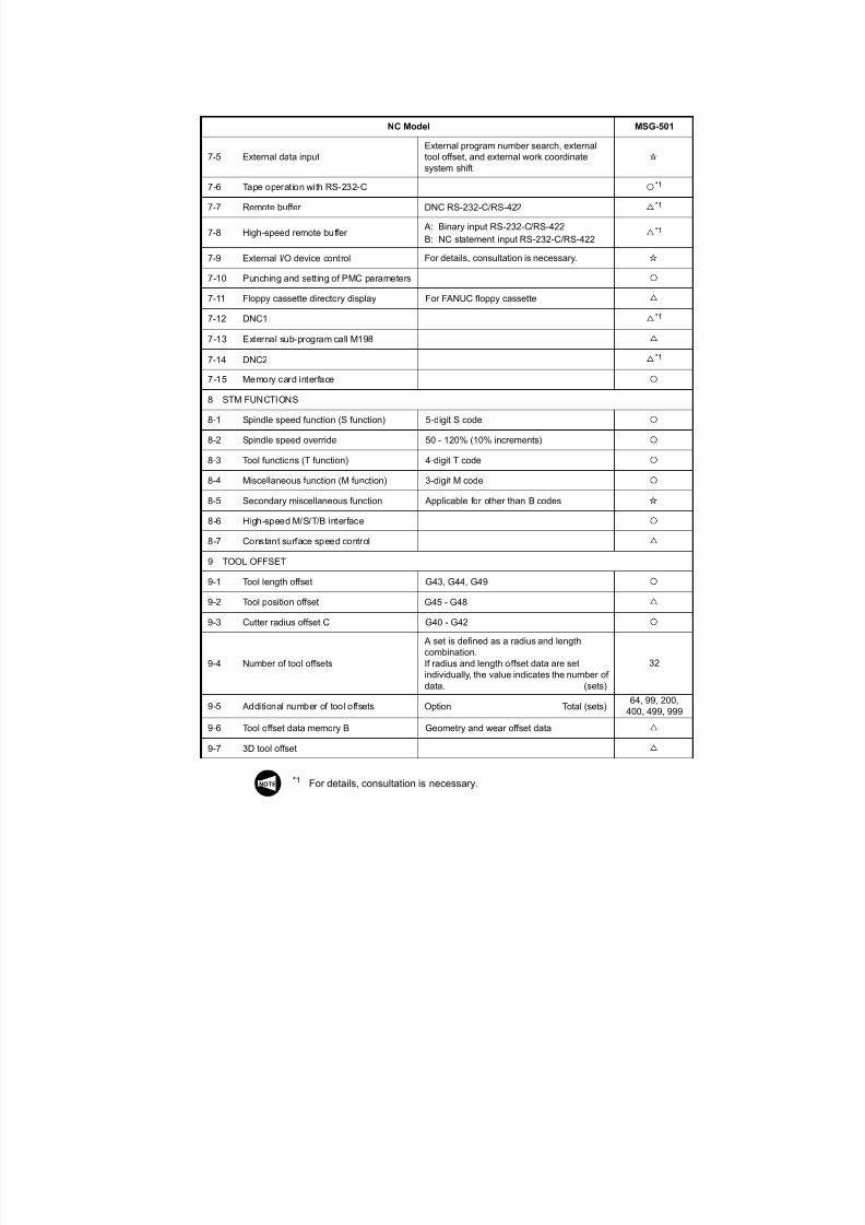
*1 For details consultation is necessary
NC Model MSG-501
7-5 External data inputExternal program number search, externaltool offset, and external work coordinatesystem shift
7-6 Tape operation with RS-232-C *1
7-7 Remote buffer DNC RS-232-C/RS-422 *1
7-8 High-speed remote buffer A: Binary input RS-232-C/RS-422
B: NC statement input RS-232-C/RS-422*1
7-9 External I/O device control For details, consultation is necessary.
7-10 Punching and setting of PMC parameters
7-11 Floppy cassette directory display For FANUC floppy cassette7-12 DNC1 *1
7-13 External sub-program call M198
7-14 DNC2 *1
7-15 Memory card interface
8 STM FUNCTIONS
8-1 Spindle speed function (S function) 5-digit S code
8-2 Spindle speed override 50 - 120% (10% increments)
8-3 Tool functions (T function) 4-digit T code
8-4 Miscellaneous function (M function) 3-digit M code
8-5 Secondary miscellaneous function Applicable for other than B codes
8-6 High-speed M/S/T/B interface
8-7 Constant surface speed control
9 TOOL OFFSET
9-1 Tool length offset G43, G44, G49
9-2 Tool position offset G45 - G489-3 Cutter radius offset C G40 - G42
9-4 Number of tool offsets
A set is defined as a radius and lengthcombination.If radius and length offset data are setindividually, the value indicates the number ofdata. (sets)
32
9-5 Additional number of tool offsets Option Total (sets)64, 99, 200,
400, 499, 999
9-6 Tool offset data memory B Geometry and wear offset data
9-7 3D tool offset
NOTE

7/21/2019 MORISEIKI MAINTENANCE CLASS
http://slidepdf.com/reader/full/moriseiki-maintenance-class 49/409
7/21/2019 MORISEIKI MAINTENANCE CLASS
http://slidepdf.com/reader/full/moriseiki-maintenance-class 50/409
NC Model MSG-501
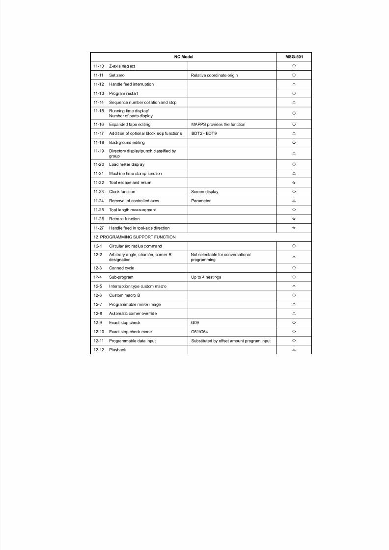
11-10 Z-axis neglect11-11 Set zero Relative coordinate origin
11-12 Handle feed interruption
11-13 Program restart
11-14 Sequence number collation and stop
11-15 Running time display/Number of parts display
11-16 Expanded tape editing MAPPS provides the function
11-17 Addition of optional block skip functions BDT2 - BDT9
11-18 Background editing
11-19 Directory display/punch classified bygroup
11-20 Load meter display
11-21 Machine time stamp function
11-22 Tool escape and return
11-23 Clock function Screen display
11-24 Removal of controlled axes Parameter
11-25 Tool length measurement
11-26 Retrace function
11-27 Handle feed in tool-axis direction
12 PROGRAMMING SUPPORT FUNCTION
12-1 Circular arc radius command
12-2 Arbitrary angle, chamfer, corner Rdesignation
Not selectable for conversationalprogramming
12-3 Canned cycle
12-4 Sub-program Up to 4 nestings
12-5 Interruption type custom macro
12-6 Custom macro B
12-7 Programmable mirror image
12-8 Automatic corner override
12-9 Exact stop check G09
12-10 Exact stop check mode G61/G64
12-11 Programmable data input Substituted by offset amount program input
12-12 Playback
7/21/2019 MORISEIKI MAINTENANCE CLASS
http://slidepdf.com/reader/full/moriseiki-maintenance-class 51/409
7/21/2019 MORISEIKI MAINTENANCE CLASS
http://slidepdf.com/reader/full/moriseiki-maintenance-class 52/409
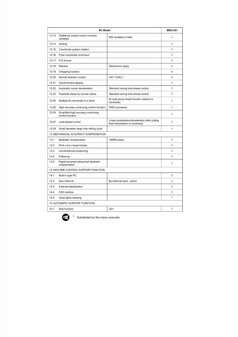
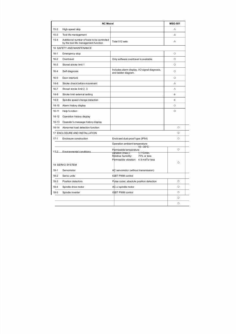
NC Model MSG-501
15-2 High-speed skip
15-3 Tool life management
15-4 Additional number of tools to be controlledby the tool life management function Total 512 sets
16 SAFETY AND MAINTENANCE
16-1 Emergency stop
16-2 Overtravel Only software overtravel is available.
16-3 Stored stroke limit 1
16-4 Self-diagnosisIncludes alarm display, I/O signal diagnosis,and ladder diagram.
16-5 Door interlock
16-6 Stroke check before movement
16-7 Stored stroke limit 2, 3
16-8 Stroke limit external setting
16-9 Spindle speed change detection
16-10 Alarm history display
16-11 Help function
16-12 Operation history display
16-13 Operator’s message history display
16-14 Abnormal load detection function
17 ENCLOSURE AND INSTALLATION
17-1 Enclosure construction Enclosed dust-proof type (IP54)
17-2 Environmental conditions
Operation ambient temperature:10 - 35C
Permissible temperaturevariation (max.): 1.1C/min.Relative humidity: 75% or less
Permissible vibration: 4.9 m/s2 or less
18 SERVO SYSTEM
18-1 Servomotor AC servomotor (without transmission)
18-2 Servo units IGBT PWM control
18-3 Position detectors Pulse coder, absolute position detection
18-4 Spindle drive motor AC i spindle motor
18-5 Spindle inverter IGBT PWM control
7/21/2019 MORISEIKI MAINTENANCE CLASS
http://slidepdf.com/reader/full/moriseiki-maintenance-class 53/409

7/21/2019 MORISEIKI MAINTENANCE CLASS
http://slidepdf.com/reader/full/moriseiki-maintenance-class 54/409
7/21/2019 MORISEIKI MAINTENANCE CLASS
http://slidepdf.com/reader/full/moriseiki-maintenance-class 55/409
7/21/2019 MORISEIKI MAINTENANCE CLASS
http://slidepdf.com/reader/full/moriseiki-maintenance-class 56/409

7/21/2019 MORISEIKI MAINTENANCE CLASS
http://slidepdf.com/reader/full/moriseiki-maintenance-class 57/409
7/21/2019 MORISEIKI MAINTENANCE CLASS
http://slidepdf.com/reader/full/moriseiki-maintenance-class 58/409
7/21/2019 MORISEIKI MAINTENANCE CLASS
http://slidepdf.com/reader/full/moriseiki-maintenance-class 59/409
7/21/2019 MORISEIKI MAINTENANCE CLASS
http://slidepdf.com/reader/full/moriseiki-maintenance-class 60/409

7/21/2019 MORISEIKI MAINTENANCE CLASS
http://slidepdf.com/reader/full/moriseiki-maintenance-class 61/409
7/21/2019 MORISEIKI MAINTENANCE CLASS
http://slidepdf.com/reader/full/moriseiki-maintenance-class 62/409
7/21/2019 MORISEIKI MAINTENANCE CLASS
http://slidepdf.com/reader/full/moriseiki-maintenance-class 63/409
7/21/2019 MORISEIKI MAINTENANCE CLASS
http://slidepdf.com/reader/full/moriseiki-maintenance-class 64/409
7/21/2019 MORISEIKI MAINTENANCE CLASS
http://slidepdf.com/reader/full/moriseiki-maintenance-class 65/409
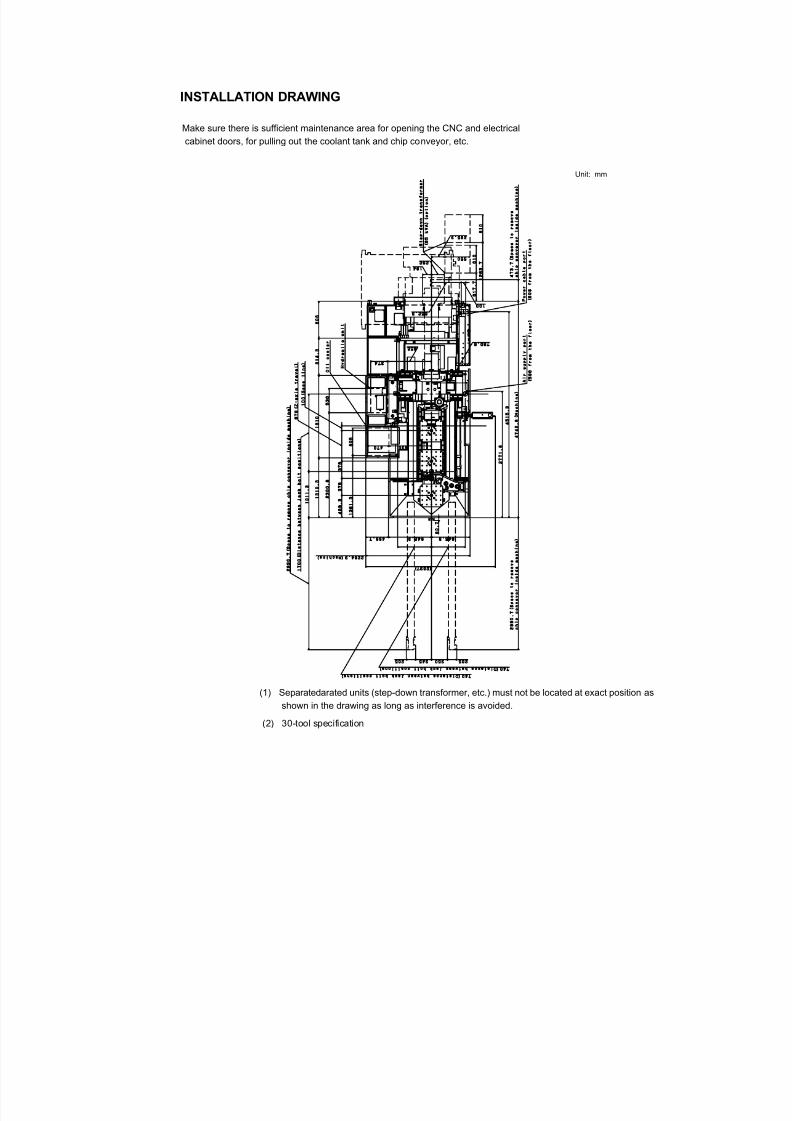
INSTALLATION DRAWING
Make sure there is sufficient maintenance area for opening the CNC and electrical
cabinet doors, for pulling out the coolant tank and chip conveyor, etc.
Unit: mm
(1) Separatedarated units (step-down transformer, etc.) must not be located at exact positionshown in the drawing as long as interference is avoided.
7/21/2019 MORISEIKI MAINTENANCE CLASS
http://slidepdf.com/reader/full/moriseiki-maintenance-class 66/409
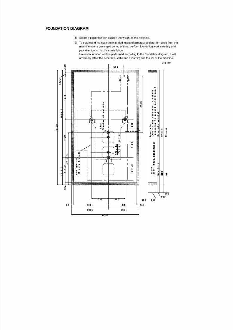
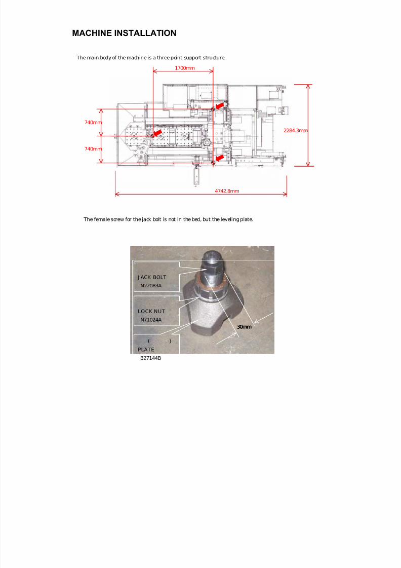
FOUNDATION DIAGRAM
(1) Select a place that can support the weight of the machine.
(2) To obtain and maintain the intended levels of accuracy and performance from the
machine over a prolonged period of time, perform foundation work carefully and
pay attention to machine installation.
Unless foundation work is performed according to the foundation diagram, it will
adversely affect the accuracy (static and dynamic) and the life of the machine.
Unit: mm
7/21/2019 MORISEIKI MAINTENANCE CLASS
http://slidepdf.com/reader/full/moriseiki-maintenance-class 67/409
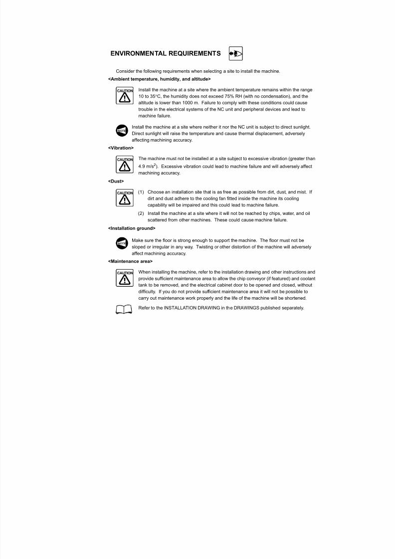
ENVIRONMENTAL REQUIREMENTS
Consider the following requirements when selecting a site to install the machine.
<Ambient temperature, humidity, and altitude>
Install the machine at a site where the ambient temperature remains within the range
10 to 35C, the humidity does not exceed 75% RH (with no condensation), and the
altitude is lower than 1000 m. Failure to comply with these conditions could cause
trouble in the electrical systems of the NC unit and peripheral devices and lead to
machine failure.
Install the machine at a site where neither it nor the NC unit is subject to direct sunlight.
Direct sunlight will raise the temperature and cause thermal displacement, adversely
affecting machining accuracy.
<Vibration>
The machine must not be installed at a site subject to excessive vibration (greater than
4.9 m/s2). Excessive vibration could lead to machine failure and will adversely affect
machining accuracy.
<Dust>
(1) Choose an installation site that is as free as possible from dirt, dust, and mist. If
dirt and dust adhere to the cooling fan fitted inside the machine its cooling
capability will be impaired and this could lead to machine failure.(2) Install the machine at a site where it will not be reached by chips, water, and oil
scattered from other machines. These could cause machine failure.
<Installation ground>
Make sure the floor is strong enough to support the machine. The floor must not be
sloped or irregular in any way. Twisting or other distortion of the machine will adversely
affect machining accuracy.
<Maintenance area>
When installing the machine, refer to the installation drawing and other instructions and
provide sufficient maintenance area to allow the chip conveyor (if featured) and coolanttank to be removed, and the electrical cabinet door to be opened and closed, without
difficulty. If you do not provide sufficient maintenance area it will not be possible to
carry out maintenance work properly and the life of the machine will be shortened.
Refer to the INSTALLATION DRAWING in the DRAWINGS published separately.
CAUTION
NOTE
CAUTION
CAUTION
NOTE
CAUTION
7/21/2019 MORISEIKI MAINTENANCE CLASS
http://slidepdf.com/reader/full/moriseiki-maintenance-class 68/409
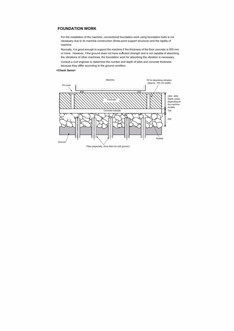
FOUNDATION WORK
For the installation of the machine, conventional foundation work using foundation bolts is not
necessary due to its machine construction (three-point support structure) and the rigidity ofmachine.
Normally, it is good enough to support the machine if the thickness of the floor concrete is 500 mm
or more. However, if the ground does not have sufficient strength and is not capable of absorbing
the vibrations of other machines, the foundation work for absorbing the vibration is necessary.
Consult a civil engineer to determine the number and depth of piles and concrete thickness
because they differ according to the ground condition.
<Check items>
Concrete
Machine
Pit cover
Pit for absorbing vibration(Approx. 150 mm width)
Rubble
Piles (especially, drive them for soft ground.)
Ground
Concrete subslab 100
200
(300 - 800)Depth variesdepending onthe machinemodels.
7/21/2019 MORISEIKI MAINTENANCE CLASS
http://slidepdf.com/reader/full/moriseiki-maintenance-class 69/409
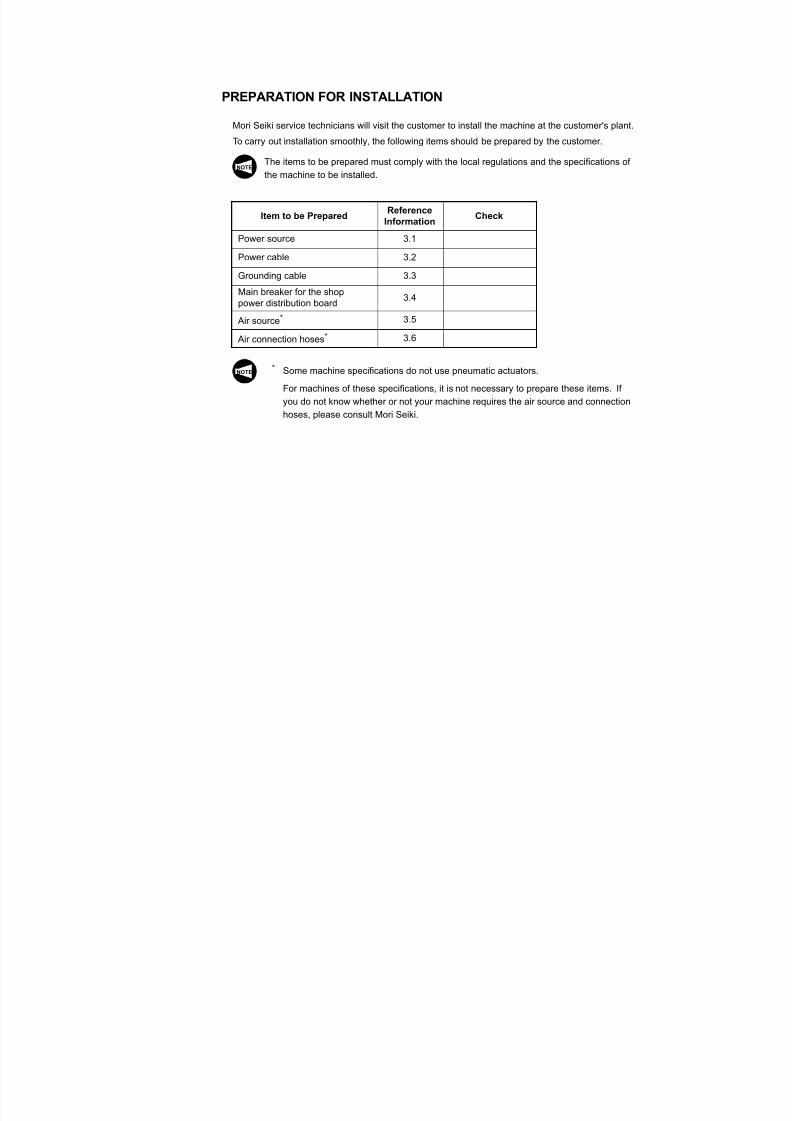
PREPARATION FOR INSTALLATION
Mori Seiki service technicians will visit the customer to install the machine at the customer's plant.
To carry out installation smoothly, the following items should be prepared by the customer.
The items to be prepared must comply with the local regulations and the specifications of
the machine to be installed.
* Some machine specifications do not use pneumatic actuators.
For machines of these specifications, it is not necessary to prepare these items. If
you do not know whether or not your machine requires the air source and connection
hoses, please consult Mori Seiki.
Item to be PreparedReference
InformationCheck
Power source 3.1
Power cable 3.2
Grounding cable 3.3Main breaker for the shoppower distribution board
3.4
Air source* 3.5
Air connection hoses* 3.6
NOTE
NOTE
7/21/2019 MORISEIKI MAINTENANCE CLASS
http://slidepdf.com/reader/full/moriseiki-maintenance-class 70/409
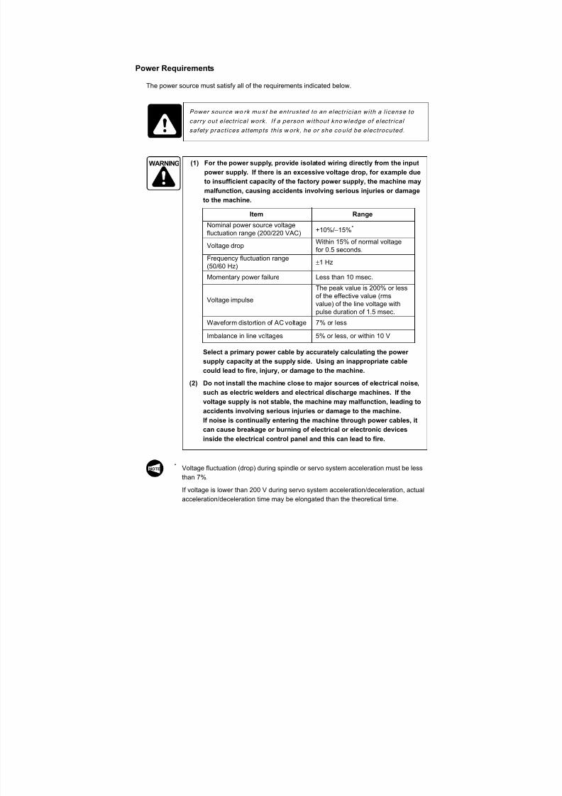
Power Requirements
The power source must satisfy all of the requirements indicated below.
* Voltage fluctuation (drop) during spindle or servo system acceleration must be less
than 7%.
If voltage is lower than 200 V during servo system acceleration/deceleration, actualacceleration/deceleration time may be elongated than the theoretical time.
DANGER Power source wo rk mu st be entrusted to an electr ic ian with a l icense to
carry out electr ical work. I f a person without kno wledge of electr ical
safety pract ices at tempts this w ork, he or she co uld be electrocuted.
WARNING (1) For the power supply, provide isolated wiring directly from the input
power supply. If there is an excessive voltage drop, for example due
to insufficient capacity of the factory power supply, the machine may
malfunction, causing accidents involving serious injuries or damage
to the machine.
Select a primary power cable by accurately calculating the power
supply capacity at the supply side. Using an inappropriate cable
could lead to fire, injury, or damage to the machine.
(2) Do not install the machine close to major sources of electrical noise,
such as electric welders and electrical discharge machines. If thevoltage supply is not stable, the machine may malfunction, leading to
accidents involving serious injuries or damage to the machine.
If noise is continually entering the machine through power cables, it
can cause breakage or burning of electrical or electronic devices
inside the electrical control panel and this can lead to fire.
Item Range
Nominal power source voltagefluctuation range (200/220 VAC) +10%/15%*
Voltage dropWithin 15% of normal voltagefor 0.5 seconds.
Frequency fluctuation range(50/60 Hz)
1 Hz
Momentary power failure Less than 10 msec.
Voltage impulse
The peak value is 200% or less
of the effective value (rmsvalue) of the line voltage withpulse duration of 1.5 msec.
Waveform distortion of AC voltage 7% or less
Imbalance in line voltages 5% or less, or within 10 V
NOTE
7/21/2019 MORISEIKI MAINTENANCE CLASS
http://slidepdf.com/reader/full/moriseiki-maintenance-class 71/409

7/21/2019 MORISEIKI MAINTENANCE CLASS
http://slidepdf.com/reader/full/moriseiki-maintenance-class 72/409
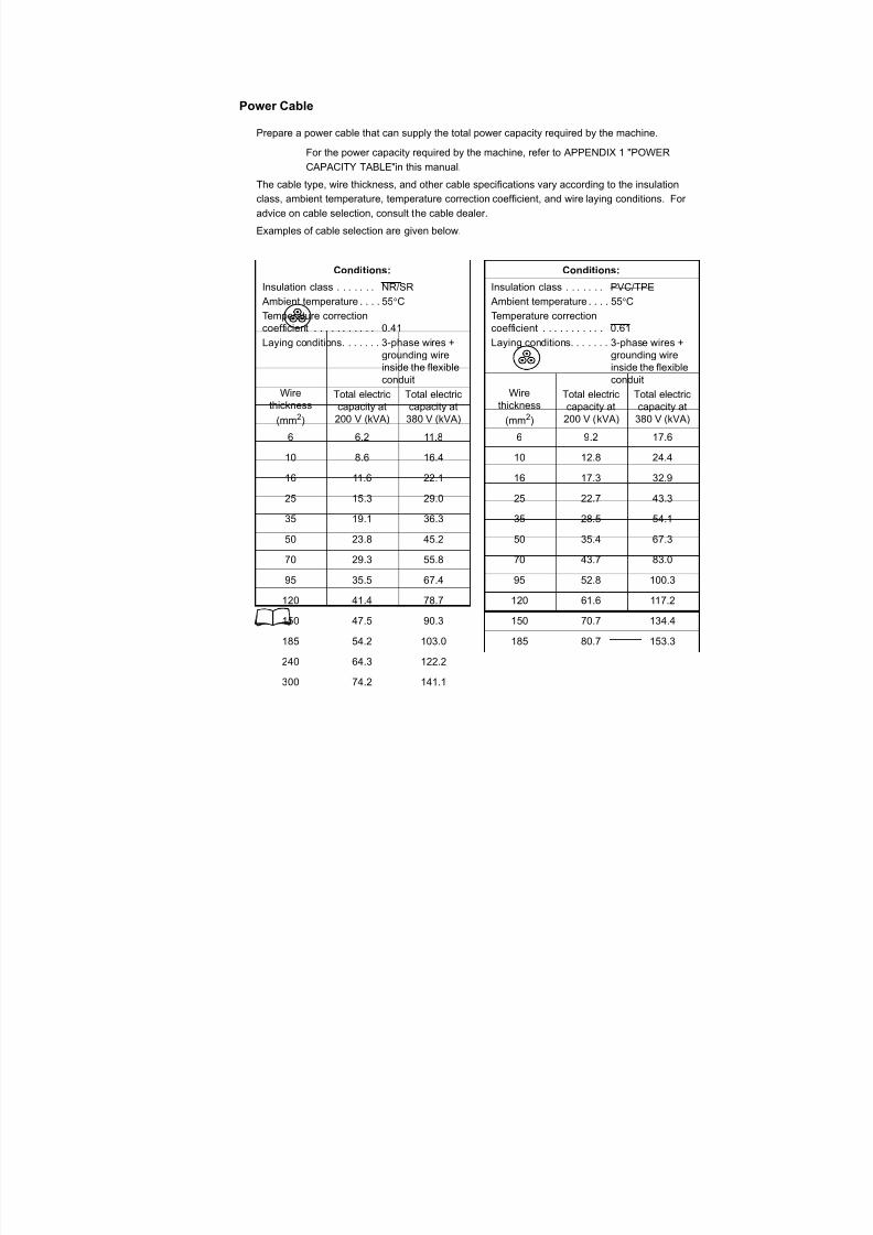
Grounding Cable
For the grounding cable, consult the cable manufacturer to select the one which is sufficient to
take earth for the machine to be installed.When selecting the grounding cable, observe the applicable local regulations where the machine
is installed.
Meaning of "Leak Current"
Indoor electrical wiring and equipment are "insulated" in order to prevent current leakage.
However, when the insulation becomes old or damaged, or when the wires/equipment are
exposed to water, current leaks out and a "leak current" is generated.
Since leak currents can cause accidents that endanger human life, such as electric shock
and fire, due care is required. Particular care is necessary when using electrical
equipment in locations where there is exposure to water (where coolant is used, for
example).
Meaning of "Electric Shock"
When a person touches wiring or electrical equipment from which current is leaking,
electricity flows through that person's body to the ground. This is an "electric shock."
If the current is weak, the result is nothing more than a "shock" in the commonly
understood sense, but if it is strong, the life of the affected person may be endangered.
Note also that water on the body of the person subject to the shock will allow the electricity
to be conducted more easily, and for this reason you must take particular care not to touch
electrical equipment with wet hands.
DANGER (1 ) Be sure to car ry out the ground ing work . If the ground ing work is not
done, there wi l l be a danger of electrocut ion.
(2 ) The ground ing wi re shou ld be as shor t as poss ib le and shou ld have
the same thickness as the power wires. The grounding resistance
should be 100 or less. If the groun ding is in effect ive, there wil l be a
danger of electrocut ion.
WARNING Do not connect any other grounding wire to the ground. If a machine such
as an electric welder or electric discharge machine is grounded to the
steel reinforcing rods in the reinforced concrete structure of the plant, do
not connect the grounding wire of the machine to the reinforcing rods too.
Unless the grounding wire is connected to an independent ground, the
machine could malfunction due to noise from other machines, leading to
accidents involving serious injuries or damage to the machine.
7/21/2019 MORISEIKI MAINTENANCE CLASS
http://slidepdf.com/reader/full/moriseiki-maintenance-class 73/409
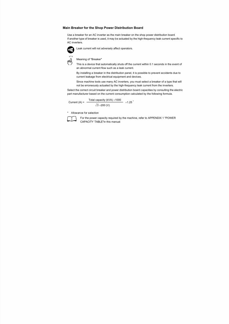
Main Breaker for the Shop Power Distribution Board
Use a breaker for an AC inverter as the main breaker on the shop power distribution board.
If another type of breaker is used, it may be actuated by the high-frequency leak current specific to AC inverters.
Leak current will not adversely affect operators.
Meaning of "Breaker"
This is a device that automatically shuts off the current within 0.1 seconds in the event of
an abnormal current flow such as a leak current.
By installing a breaker in the distribution panel, it is possible to prevent accidents due to
current leakage from electrical equipment and devices.
Since machine tools use many AC inverters, you must select a breaker of a type that will
not be erroneously actuated by the high-frequency leak current from the inverters.
Select the correct circuit breaker and power distribution board capacities by consulting the electric
part manufacturer based on the current consumption calculated by the following formula.
* Allowance for selection
For the power capacity required by the machine, refer to APPENDIX 1 "POWER
CAPACITY TABLE" in this manual.
NOTE
Current (A) =Total capacity (kVA) 1000
3 200 (V) 1.25 *
7/21/2019 MORISEIKI MAINTENANCE CLASS
http://slidepdf.com/reader/full/moriseiki-maintenance-class 74/409
Compressed Air Supply
Select a compressed air supply that can supply the required volume of compressed air at the
required pressure. For the selection, consult the compressor manufacturer.(1) Use only clean and dry air, 0.7 MPa, 10C or less.
If you use air that is moist or has a high concentration of dust, the pneumatic
devices could malfunction, causing damage to the machine. (Applies to machines
with pneumatic devices)
If the compressed air quality is not within the specified range, use a line filter,
dryer, etc. between the machine and the air source.
(2) The pressure setting of the compressor should be in the range from 0.5 to 1.0
MPa.
If the setting is higher than 1.0 MPa, pneumatic actuators used in the machine
could be damaged.
Hoses for Supplying Compressed Air
Select hoses for supplying compressed air that can comfortably withstand the compressed air
pressure. For advice on the selection, consult the hose manufacturer.
Compressed air supply port size: Rc 3/8
CAUTION

7/21/2019 MORISEIKI MAINTENANCE CLASS
http://slidepdf.com/reader/full/moriseiki-maintenance-class 75/409
7/21/2019 MORISEIKI MAINTENANCE CLASS
http://slidepdf.com/reader/full/moriseiki-maintenance-class 76/409
CARRYING THE MACHINE
When the machine is delivered to your shop, Mori Seiki's service technicians will install the
machine at the designated place. Refer to the information below if you move the machine afterinitial installation, for example due to a floor layout change.
If it becomes necessary to carry the machine due to relocation of the plant or selling of the
machine, contact Mori Seiki.
Preparation
Make the following preparations before moving the machine.
1) Before turning off the power, move each axis to the position where it should be fixed.
2) Turn off the main switch on the electrical cabinet.
3) Turn off the main breaker on the shop power distribution board.
4) Disconnect the power cable and the grounding wire.
5) Fix the machine units with transit clamps.
6) Turn off the compressed air.
7) Remove the compressed air supply hose.
8) Disconnect the cables of the coolant motor and chip conveyor motor.
9) Disconnect the cables and pipes of the oil cooler (fan cooler).
10) Remove the coolant tank and the chip conveyor from the machine.
11) Drain the coolant from the coolant tank.
12) Remove the jack bolts.
7/21/2019 MORISEIKI MAINTENANCE CLASS
http://slidepdf.com/reader/full/moriseiki-maintenance-class 77/409
Carrying the Machine by Hoisting
Observe the following cautions when carrying the machine by hoisting.
WARNING (1) Only a qualified technician should perform machine hoisting work.
Operation of the crane or forklift by a person unfamiliar with safe
operation practices could lead to accidents involving serious injuries
or damage to the machine.
(2) Use only wires, shackles and jigs of the dimensions specified in the
manual. They must be strong enough to support the mass of the
machine. Check the mass of the machine by referring to the
specifications in this manual. If the machine is hoisted using
equipment that cannot bear its mass it will fall, causing serious
injuries or damage to the machine.
(3) Make sure that the machine is well balanced in both the crosswise
and lengthwise directions after hoisting it a little above the floor. If
you continue to hoist the machine although it is not properly
balanced, it will fall, causing serious injuries or damage to the
machine.
(4) If two or more people work together to lift the machine, they must
work carefully while exchanging signals. If someone operates the
machine or the crane inadvertently when other people are working
inside or close to the machine, it could cause serious injuries.
(5) Before hoisting the machine, check that no tools, rags, etc., have
been left inside it. When the machine is lifted, these articles could fall
out and injure plant personnel or damage the machine.
(6) If a crane is used to hoist the machine, do not carry the machine while
it is lifted to an excessive height. Lifting the machine excessively
high when carrying it will create more potential hazards than when
carrying it at a lower height.
(7) When moving the machine with a forklift, do not lift it high above the
ground. If it is moved in this condition, it may become unbalanced
and fall, or the forklift may topple over, causing serious injuries ordamage to the machine.
(8) Use a crane or forklift that can comfortably bear the mass of the
machine. If a crane or forklift without sufficient capacity to lift the
machine is used, the machine will fall, causing serious injuries or
damage to the machine.
(9) Lift the machine while it is supported at its center of gravity. If you
select a point other than the center of gravity, it may become
unbalanced and fall, causing serious injuries or damage to the
machine.
7/21/2019 MORISEIKI MAINTENANCE CLASS
http://slidepdf.com/reader/full/moriseiki-maintenance-class 78/409
(1) If a rust-preventive coating is applied to the slideway surfaces, it must be removed
completely. Attempting axis feed while rust-preventive coating remains on the
slideways could cause machine failure.
(2) All transit clamps must be removed before switching the power ON. If a clampcannot be removed without switching the power ON first, remove it immediately
after switching the power ON. If axis feed is attempted while a clamp is still in
place, the machine will be damaged.
(3) Before hoisting the machine, check that all of its parts are clamped. Lifting the
machine while any of the parts is not clamped adequately could damage the
machine.
(4) When installing the machine, mount the coolant tank and the chip bucket by
pushing them into an appropriate position. Otherwise, coolant may be splashed
around the machine causing the operator or persons around the machine to topple
down and get injured.
(1) When moving the machine with rollers, set the number of rollers, and the material that
they are made of, so as to ensure that they can support the mass of the machine.
Also use skid and leading boards that can support the mass of the machine. If they
cannot support the mass of the machine the rollers, skid, or leading board may be
distorted, making it impossible to move the machine.
(2) After the machine has been installed, it must be leveled. Adjust the machine's crown
and distortion values according to the Accuracy Test Results Chart delivered with the
machine. If this adjustment is not carried out properly, machining accuracy will be
adversely affected.
CAUTION
NOTE
7/21/2019 MORISEIKI MAINTENANCE CLASS
http://slidepdf.com/reader/full/moriseiki-maintenance-class 79/409
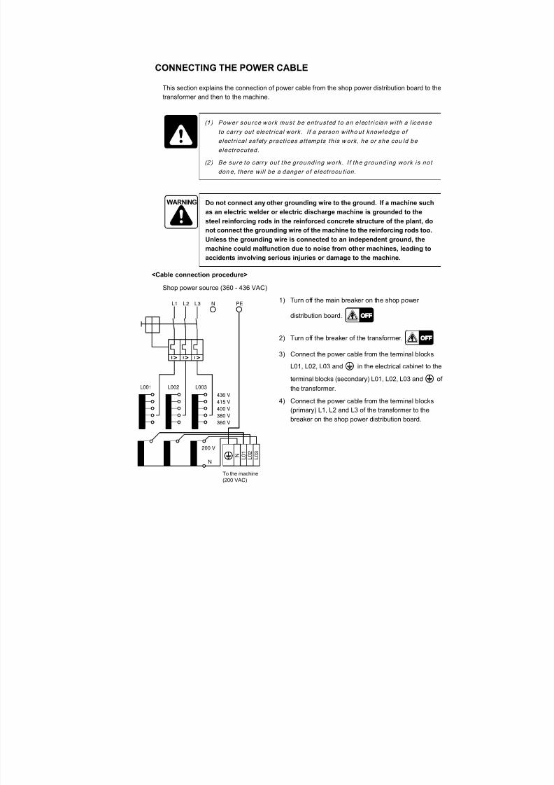
CONNECTING THE POWER CABLE
This section explains the connection of power cable from the shop power distribution board to the
transformer and then to the machine.
<Cable connection procedure>
Shop power source (360 - 436 VAC)1) Turn off the main breaker on the shop power
distribution board.
2) Turn off the breaker of the transformer.
3) Connect the power cable from the terminal blocks
L01, L02, L03 and in the electrical cabinet to the
terminal blocks (secondary) L01, L02, L03 and of
the transformer.
4) Connect the power cable from the terminal blocks
(primary) L1, L2 and L3 of the transformer to the
breaker on the shop power distribution board.
DANGER (1 ) Power source work must be entrus ted to an e lec t r ic ian wi th a l icense
to carry out electr ical work. I f a person witho ut knowledge of
electr ica l safety pract ices at tempts this w ork, he or she cou ld be
electrocuted.
(2 ) Be sure to car ry out the ground ing work . I f the ground ing work is not
don e, there wil l be a danger of electrocu tion.
WARNING Do not connect any other grounding wire to the ground. If a machine such
as an electric welder or electric discharge machine is grounded to the
steel reinforcing rods in the reinforced concrete structure of the plant, do
not connect the grounding wire of the machine to the reinforcing rods too.
Unless the grounding wire is connected to an independent ground, the
machine could malfunction due to noise from other machines, leading to
accidents involving serious injuries or damage to the machine.
L1 L2 L3 N PE
L001 L002 L003436 V
415 V
400 V
380 V
360 V
200 V
N
N L 0 1
L 0 2
L 0 3
To the machine(200 VAC)
7/21/2019 MORISEIKI MAINTENANCE CLASS
http://slidepdf.com/reader/full/moriseiki-maintenance-class 80/409
7/21/2019 MORISEIKI MAINTENANCE CLASS
http://slidepdf.com/reader/full/moriseiki-maintenance-class 81/409
CONNECTION OF COMPRESSED AIR SUPPLY HOSE
Follow the procedure below to connect the compressed air supply hose.
1) Turn off the power.
2) Connect the compressed air supply hose from the air source to the air supply port (Rc 3/8) in
the air panel of the machine.
3) Start the compressor to supply the compressed air to the machine.
4) Make sure that there is no air leak at hose joints and pneumatic actuators.
5) Adjust the compressed air pressure to the specified value with the regulator in the air panel.
For the correct air pressure, refer to page MACHINE SPECIFICATIONS in the
MAINTENANCE INFORMATION published separately. REMOVING TRANSIT CLAMPS
After carrying the machine to the required place, remove all transit clamps before turning on the
power.
The transit clamps that cannot be removed before turning on the power should be
removed immediately after turning on the power. Attempting axis feed while the transit
clamps are in place will damage the machine.
Keep the removed transit clamps so that they will not be lost.
CAUTION
7/21/2019 MORISEIKI MAINTENANCE CLASS
http://slidepdf.com/reader/full/moriseiki-maintenance-class 82/409

7/21/2019 MORISEIKI MAINTENANCE CLASS
http://slidepdf.com/reader/full/moriseiki-maintenance-class 83/409
7/21/2019 MORISEIKI MAINTENANCE CLASS
http://slidepdf.com/reader/full/moriseiki-maintenance-class 84/409
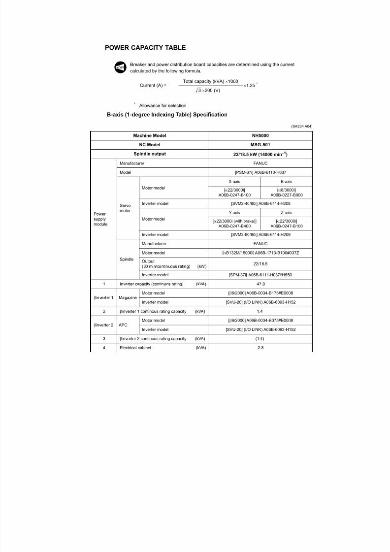
POWER CAPACITY TABLE
Breaker and power distribution board capacities are determined using the current
calculated by the following formula.
* Allowance for selection
B-axis (1-degree Indexing Table) Specification
(I94234 A04)
Machine Model NH5000
NC Model MSG-501
Spindle output 22/18.5 kW (14000 min1)
Powersupplymodule
Manufacturer FANUC
Model [PSM-37i] A06B-6110-H037
Servomotor
Motor model
X-axis B-axis
[22/3000i] A06B-0247-B100
[8/3000i] A06B-0227-B000
Inverter model [SVM2-40/80i] A06B-6114-H208
Motor model
Y-axis Z-axis
[22/3000i (with brake)] A06B-0247-B400
[22/3000i] A06B-0247-B100
Inverter model [SVM2-80/80i] A06B-6114-H209
Spindle
Manufacturer FANUC
Motor model [B132M/15000i] A06B-1713-B100#037Z
Output(30 min/continuous rating) (kW)
22/18.5
Inverter model [SPM-37i] A06B-6111-H037#H550
1 Inverter capacity (continuos rating) (kVA) 43.0
inverter 1 MagazineMotor model [6/2000] A06B-0034-B175#E0008
Inverter model [SVU-20] (I/O LINK) A06B-6093-H152
2 inverter 1 continous rating capacity (kVA) 1.4
inverter 2 APCMotor model [6/2000] A06B-0034-B075#E0008
Inverter model [SVU-20] (I/O LINK) A06B-6093-H152
3 inverter 2 continous rating capacity (kVA) (1.4)
4 Electrical cabinet (kVA) 2.8
NOTE
Current (A) =Total capacity (kVA) 1000
3 200 (V) 1.25 *
7/21/2019 MORISEIKI MAINTENANCE CLASS
http://slidepdf.com/reader/full/moriseiki-maintenance-class 85/409
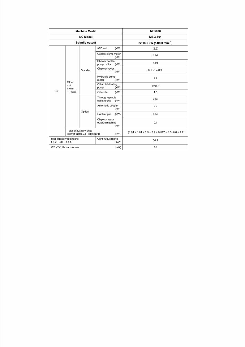
5
Other
unitmotor(kW)
Standard
ATC unit (kW) (2.2)
Coolant pump motor(kW)
1.04
Shower coolantpump motor (kW)
1.04
Chip conveyor(kW)
0.1 3 = 0.3
Hydraulic pumpmotor (kW)
2.2
Oil-air lubricatingpump (kW) 0.017
Oil cooler (kW) 1.5
Option
Through-spindlecoolant unit (kW)
7.35
Automatic coupler(kW)
0.0
Coolant gun (kW) 0.52
Chip conveyoroutside machine
(kW)0.1
Total of auxiliary units[power factor 0.8] (standard) (kVA)
(1.04 + 1.04 + 0.3 + 2.2 + 0.017 + 1.5)/0.8 = 7.7
Total capacity (standard)1 + 2 + (3) + 4 + 5
Continuous rating(kVA)
54.9
220 V 50 Hz transformer (kVA) 20
Machine Model NH5000
NC Model MSG-501
Spindle output 22/18.5 kW (14000 min
1)
7/21/2019 MORISEIKI MAINTENANCE CLASS
http://slidepdf.com/reader/full/moriseiki-maintenance-class 86/409

7/21/2019 MORISEIKI MAINTENANCE CLASS
http://slidepdf.com/reader/full/moriseiki-maintenance-class 87/409
7/21/2019 MORISEIKI MAINTENANCE CLASS
http://slidepdf.com/reader/full/moriseiki-maintenance-class 88/409
7/21/2019 MORISEIKI MAINTENANCE CLASS
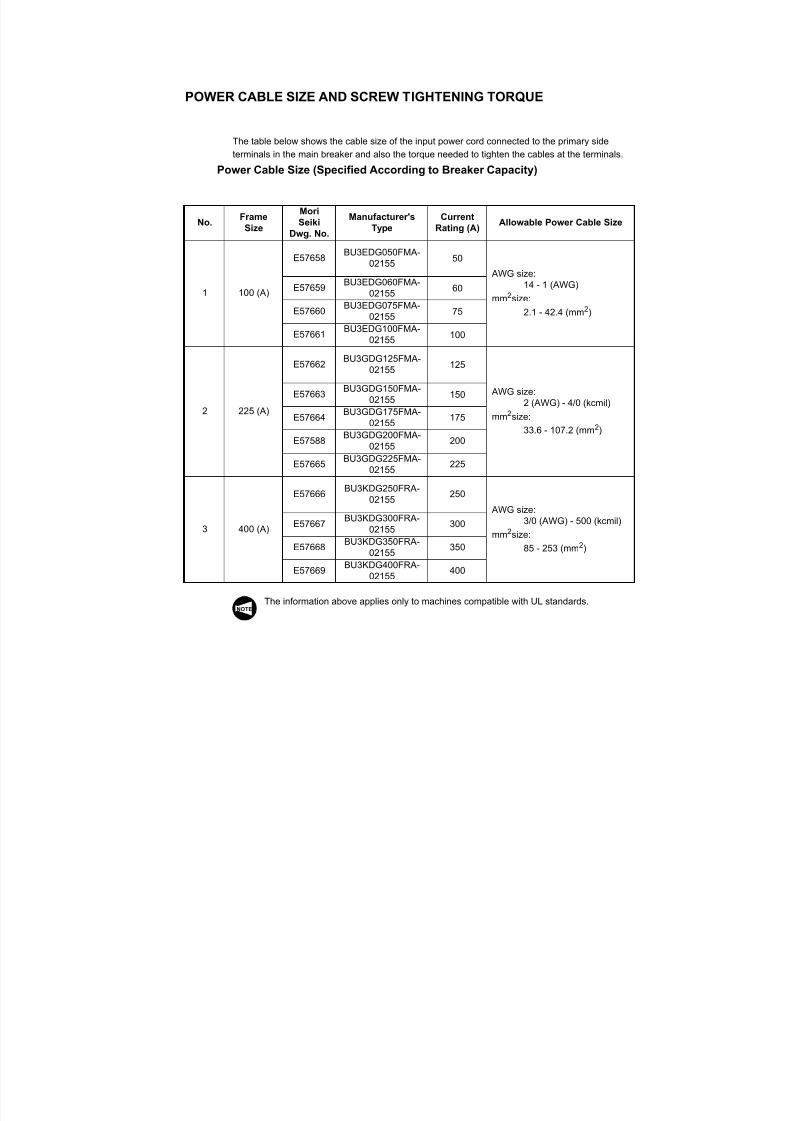
http://slidepdf.com/reader/full/moriseiki-maintenance-class 89/409
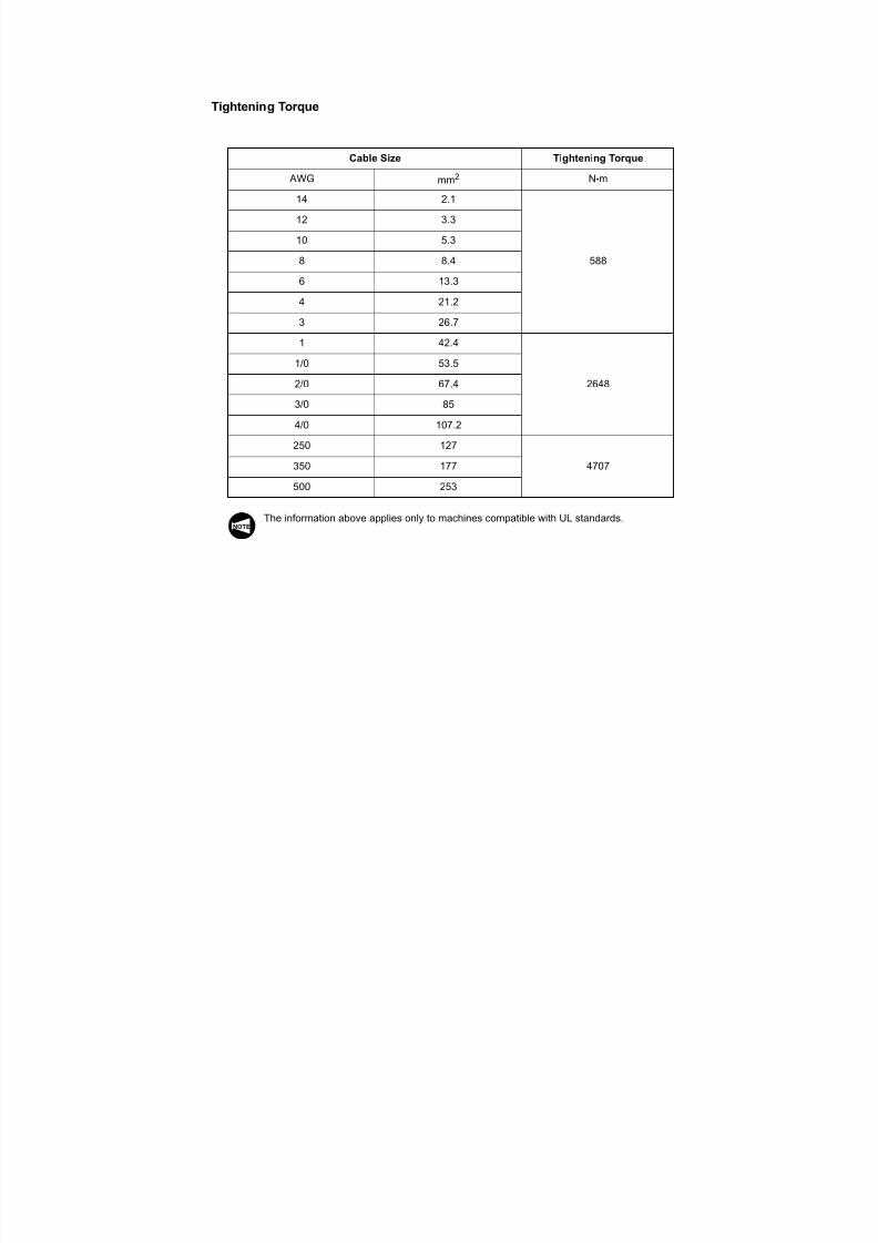
Tightening Torque
The information above applies only to machines compatible with UL standards.
Cable Size Tightening Torque
AWG mm2 N•m
14 2.1
588
12 3.3
10 5.3
8 8.4
6 13.3
4 21.23 26.7
1 42.4
2648
1/0 53.5
2/0 67.4
3/0 85
4/0 107.2
250 127
4707350 177
500 253
NOTE
7/21/2019 MORISEIKI MAINTENANCE CLASS
http://slidepdf.com/reader/full/moriseiki-maintenance-class 90/409
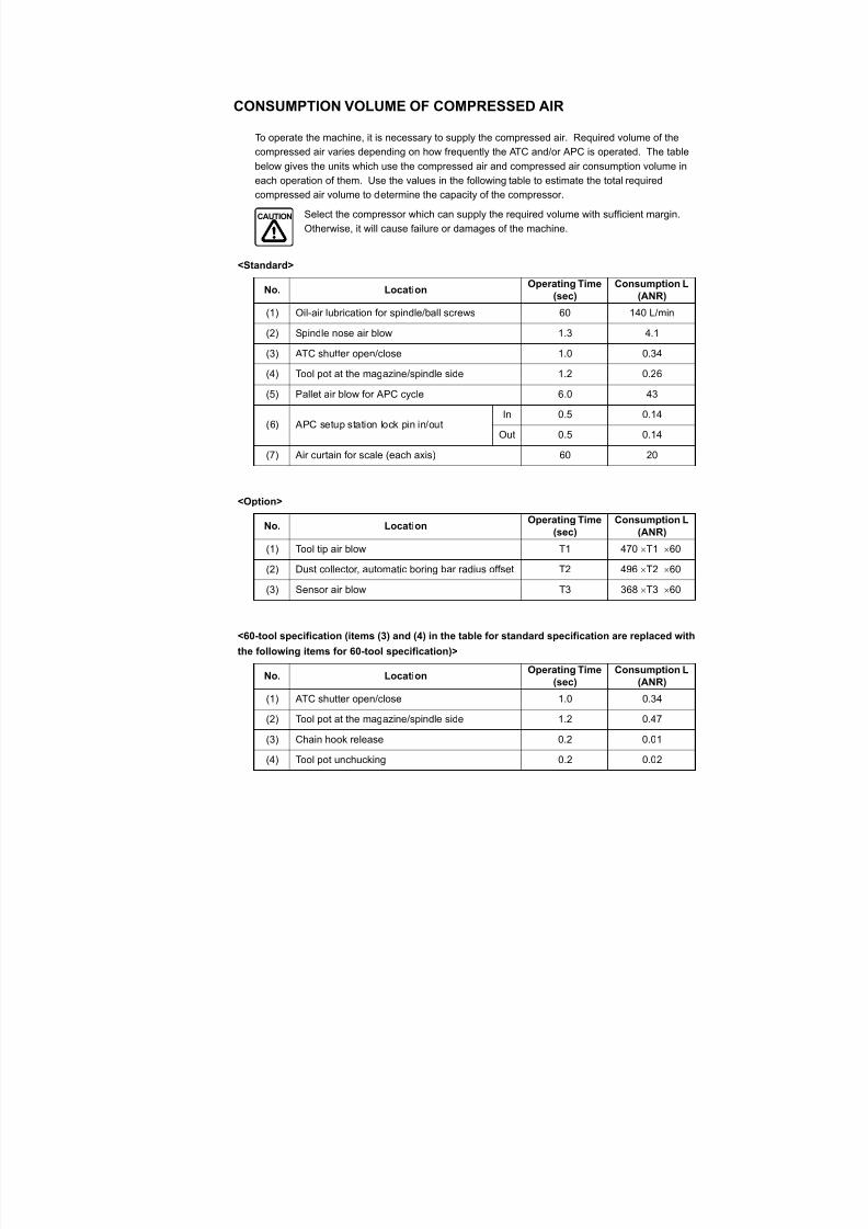
CONSUMPTION VOLUME OF COMPRESSED AIR
To operate the machine, it is necessary to supply the compressed air. Required volume of the
compressed air varies depending on how frequently the ATC and/or APC is operated. The tablebelow gives the units which use the compressed air and compressed air consumption volume in
each operation of them. Use the values in the following table to estimate the total required
compressed air volume to determine the capacity of the compressor.
Select the compressor which can supply the required volume with sufficient margin.
Otherwise, it will cause failure or damages of the machine.
<Standard>
<Option>
<60-tool specification (items (3) and (4) in the table for standard specification are replaced with
the following items for 60-tool specification)>
No. LocationOperating Time
(sec)
Consumption L
(ANR)
(1) Oil-air lubrication for spindle/ball screws 60 140 L/min
(2) Spindle nose air blow 1.3 4.1
(3) ATC shutter open/close 1.0 0.34
(4) Tool pot at the magazine/spindle side 1.2 0.26
(5) Pallet air blow for APC cycle 6.0 43
(6) APC setup station lock pin in/outIn 0.5 0.14
Out 0.5 0.14
(7) Air curtain for scale (each axis) 60 20
No. LocationOperating Time
(sec)
Consumption L
(ANR)
(1) Tool tip air blow T1 470 T1 60
(2) Dust collector, automatic boring bar radius offset T2 496 T2 60
(3) Sensor air blow T3 368 T3 60
No. LocationOperating Time
(sec)
Consumption L
(ANR)
(1) ATC shutter open/close 1.0 0.34
(2) Tool pot at the magazine/spindle side 1.2 0.47
(3) Chain hook release 0.2 0.01
(4) Tool pot unchucking 0.2 0.02
CAUTION
7/21/2019 MORISEIKI MAINTENANCE CLASS
http://slidepdf.com/reader/full/moriseiki-maintenance-class 91/409
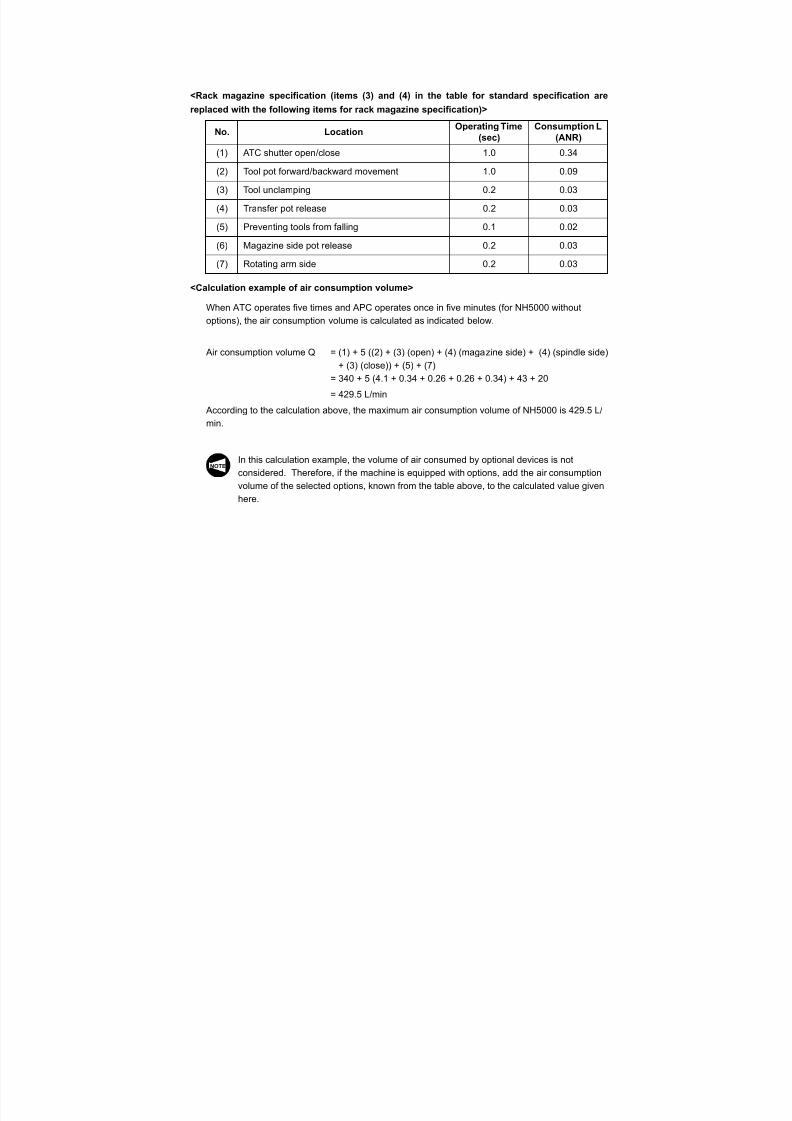
<Rack magazine specification (items (3) and (4) in the table for standard specification are
replaced with the following items for rack magazine specification)>
<Calculation example of air consumption volume>
When ATC operates five times and APC operates once in five minutes (for NH5000 without
options), the air consumption volume is calculated as indicated below.
Air consumption volume Q = (1) + 5 ((2) + (3) (open) + (4) (magazine side) + (4) (spindle side)
+ (3) (close)) + (5) + (7)
= 340 + 5 (4.1 + 0.34 + 0.26 + 0.26 + 0.34) + 43 + 20
= 429.5 L/min
According to the calculation above, the maximum air consumption volume of NH5000 is 429.5 L/
min.
In this calculation example, the volume of air consumed by optional devices is not
considered. Therefore, if the machine is equipped with options, add the air consumption
volume of the selected options, known from the table above, to the calculated value given
here.
No. LocationOperating Time
(sec)
Consumption L
(ANR)(1) ATC shutter open/close 1.0 0.34
(2) Tool pot forward/backward movement 1.0 0.09
(3) Tool unclamping 0.2 0.03
(4) Transfer pot release 0.2 0.03
(5) Preventing tools from falling 0.1 0.02
(6) Magazine side pot release 0.2 0.03
(7) Rotating arm side 0.2 0.03
NOTE
7/21/2019 MORISEIKI MAINTENANCE CLASS
http://slidepdf.com/reader/full/moriseiki-maintenance-class 92/409
7/21/2019 MORISEIKI MAINTENANCE CLASS
http://slidepdf.com/reader/full/moriseiki-maintenance-class 93/409
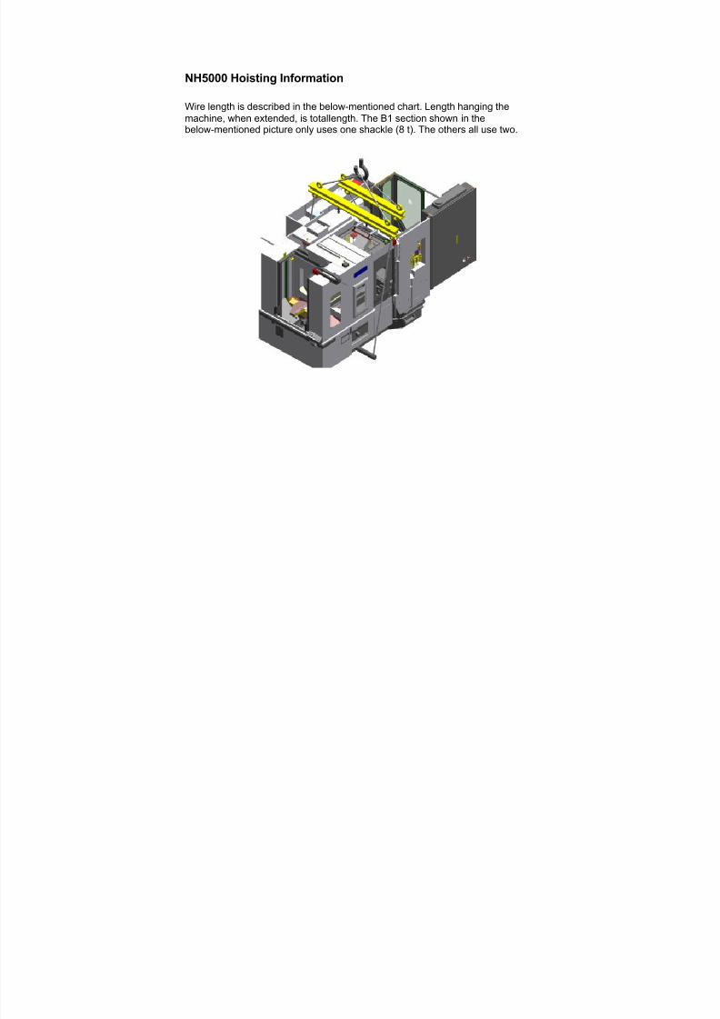
NH5000 Hoisting Information
Wire length is described in the below-mentioned chart. Length hanging themachine, when extended, is total length. The B1 section shown in thebelow-mentioned picture only uses one shackle (8 t). The others all use two.

7/21/2019 MORISEIKI MAINTENANCE CLASS
http://slidepdf.com/reader/full/moriseiki-maintenance-class 94/409
7/21/2019 MORISEIKI MAINTENANCE CLASS
http://slidepdf.com/reader/full/moriseiki-maintenance-class 95/409
7/21/2019 MORISEIKI MAINTENANCE CLASS
http://slidepdf.com/reader/full/moriseiki-maintenance-class 96/409
7/21/2019 MORISEIKI MAINTENANCE CLASS
http://slidepdf.com/reader/full/moriseiki-maintenance-class 97/409
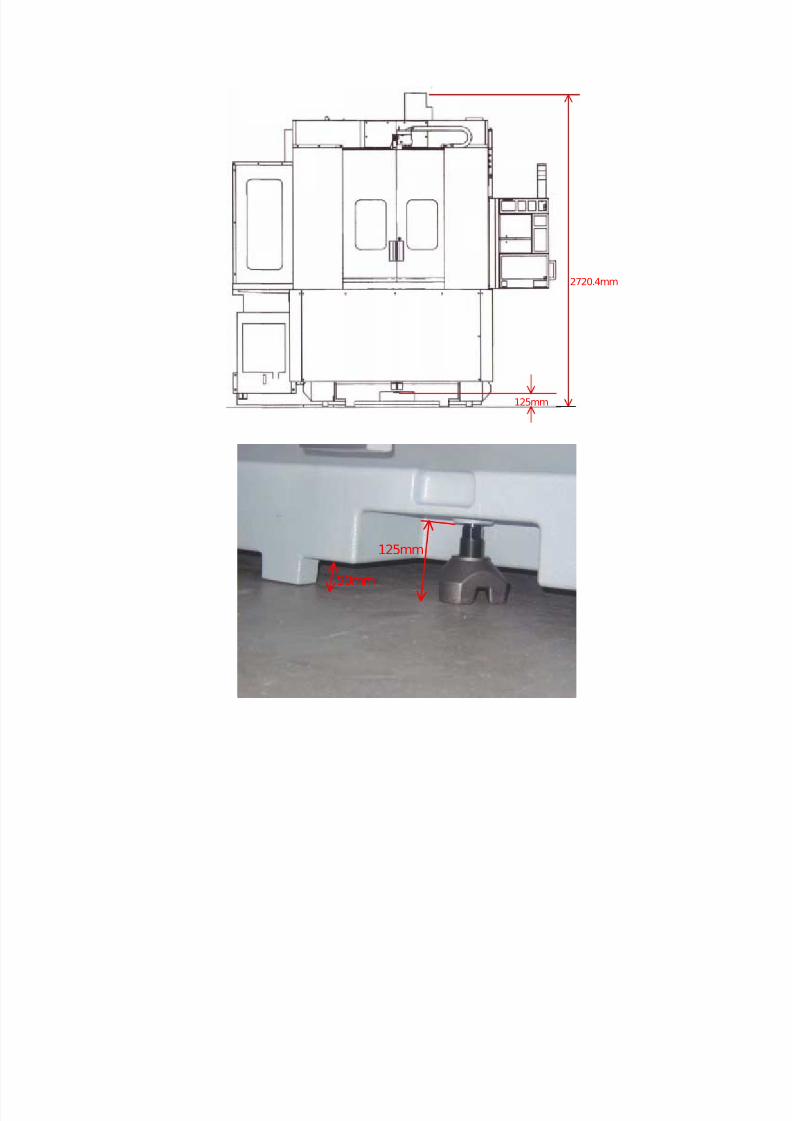
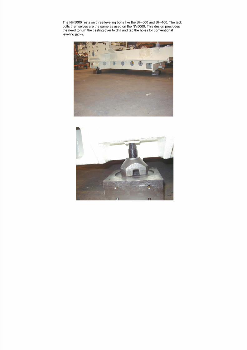
The NH5000 rests on three leveling bolts like the SH-500 and SH-400. The jackbolts themselves are the same as used on the NV5000. This design precludesthe need to turn the casting over to drill and tap the holes for conventionalleveling jacks.
7/21/2019 MORISEIKI MAINTENANCE CLASS
http://slidepdf.com/reader/full/moriseiki-maintenance-class 98/409
7/21/2019 MORISEIKI MAINTENANCE CLASS
http://slidepdf.com/reader/full/moriseiki-maintenance-class 99/409
7/21/2019 MORISEIKI MAINTENANCE CLASS
http://slidepdf.com/reader/full/moriseiki-maintenance-class 100/409
7/21/2019 MORISEIKI MAINTENANCE CLASS
http://slidepdf.com/reader/full/moriseiki-maintenance-class 101/409
7/21/2019 MORISEIKI MAINTENANCE CLASS
http://slidepdf.com/reader/full/moriseiki-maintenance-class 102/409
7/21/2019 MORISEIKI MAINTENANCE CLASS
http://slidepdf.com/reader/full/moriseiki-maintenance-class 103/409
7/21/2019 MORISEIKI MAINTENANCE CLASS
http://slidepdf.com/reader/full/moriseiki-maintenance-class 104/409
7/21/2019 MORISEIKI MAINTENANCE CLASS
http://slidepdf.com/reader/full/moriseiki-maintenance-class 105/409
7/21/2019 MORISEIKI MAINTENANCE CLASS
http://slidepdf.com/reader/full/moriseiki-maintenance-class 106/409
7/21/2019 MORISEIKI MAINTENANCE CLASS
http://slidepdf.com/reader/full/moriseiki-maintenance-class 107/409
7/21/2019 MORISEIKI MAINTENANCE CLASS
http://slidepdf.com/reader/full/moriseiki-maintenance-class 108/409

7/21/2019 MORISEIKI MAINTENANCE CLASS
http://slidepdf.com/reader/full/moriseiki-maintenance-class 109/409
7/21/2019 MORISEIKI MAINTENANCE CLASS
http://slidepdf.com/reader/full/moriseiki-maintenance-class 110/409
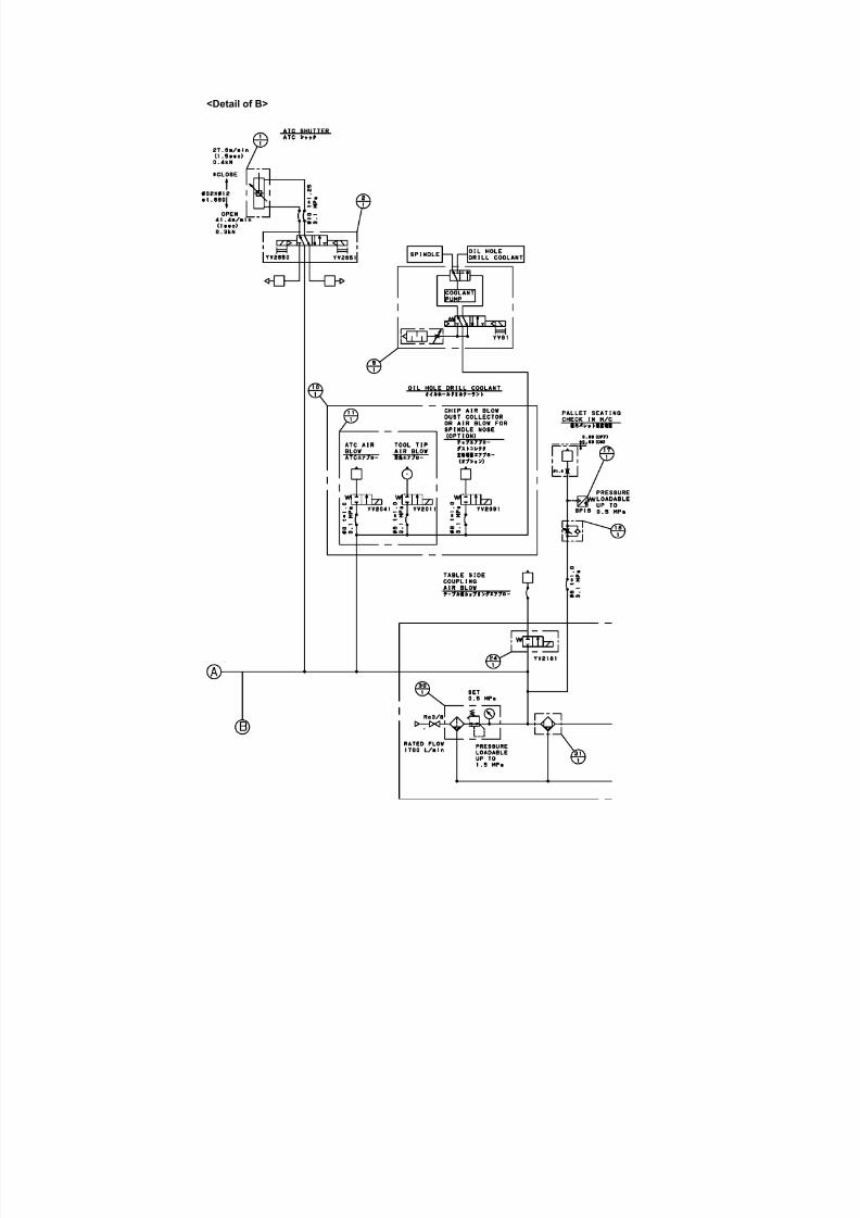
<Detail of B>
7/21/2019 MORISEIKI MAINTENANCE CLASS
http://slidepdf.com/reader/full/moriseiki-maintenance-class 111/409
7/21/2019 MORISEIKI MAINTENANCE CLASS
http://slidepdf.com/reader/full/moriseiki-maintenance-class 112/409
7/21/2019 MORISEIKI MAINTENANCE CLASS
http://slidepdf.com/reader/full/moriseiki-maintenance-class 113/409
7/21/2019 MORISEIKI MAINTENANCE CLASS
http://slidepdf.com/reader/full/moriseiki-maintenance-class 114/409
7/21/2019 MORISEIKI MAINTENANCE CLASS
http://slidepdf.com/reader/full/moriseiki-maintenance-class 115/409
7/21/2019 MORISEIKI MAINTENANCE CLASS
http://slidepdf.com/reader/full/moriseiki-maintenance-class 116/409
7/21/2019 MORISEIKI MAINTENANCE CLASS
http://slidepdf.com/reader/full/moriseiki-maintenance-class 117/409
7/21/2019 MORISEIKI MAINTENANCE CLASS
http://slidepdf.com/reader/full/moriseiki-maintenance-class 118/409
7/21/2019 MORISEIKI MAINTENANCE CLASS
http://slidepdf.com/reader/full/moriseiki-maintenance-class 119/409
7/21/2019 MORISEIKI MAINTENANCE CLASS
http://slidepdf.com/reader/full/moriseiki-maintenance-class 120/409
7/21/2019 MORISEIKI MAINTENANCE CLASS
http://slidepdf.com/reader/full/moriseiki-maintenance-class 121/409
7/21/2019 MORISEIKI MAINTENANCE CLASS
http://slidepdf.com/reader/full/moriseiki-maintenance-class 122/409
7/21/2019 MORISEIKI MAINTENANCE CLASS
http://slidepdf.com/reader/full/moriseiki-maintenance-class 123/409

7/21/2019 MORISEIKI MAINTENANCE CLASS
http://slidepdf.com/reader/full/moriseiki-maintenance-class 124/409

7/21/2019 MORISEIKI MAINTENANCE CLASS
http://slidepdf.com/reader/full/moriseiki-maintenance-class 125/409
7/21/2019 MORISEIKI MAINTENANCE CLASS
http://slidepdf.com/reader/full/moriseiki-maintenance-class 126/409
7/21/2019 MORISEIKI MAINTENANCE CLASS
http://slidepdf.com/reader/full/moriseiki-maintenance-class 127/409
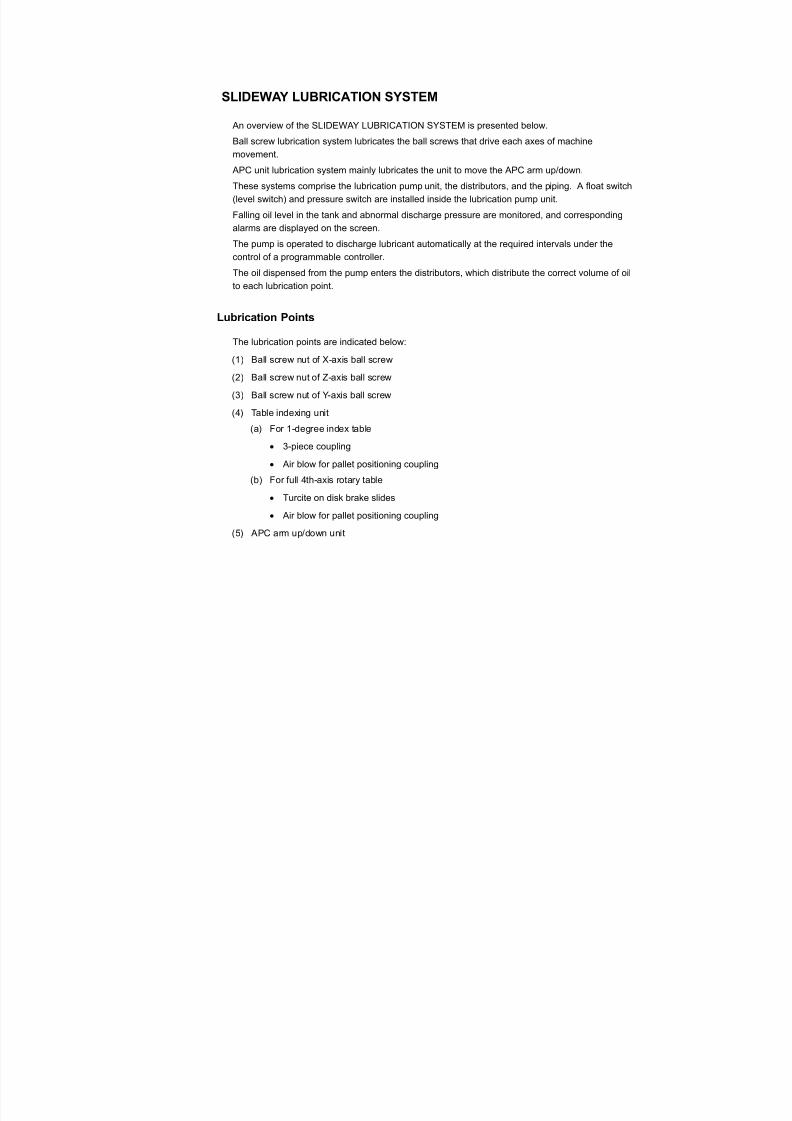
The NH5000 has two lubrication units. One is for the spindle bearings and ballnut and thesecond is for the B axis lubrication.
B Axis lubrication – VG68 Oil Spindle and Ballnut lubrication – VG32
LUBRICATION
7/21/2019 MORISEIKI MAINTENANCE CLASS
http://slidepdf.com/reader/full/moriseiki-maintenance-class 128/409
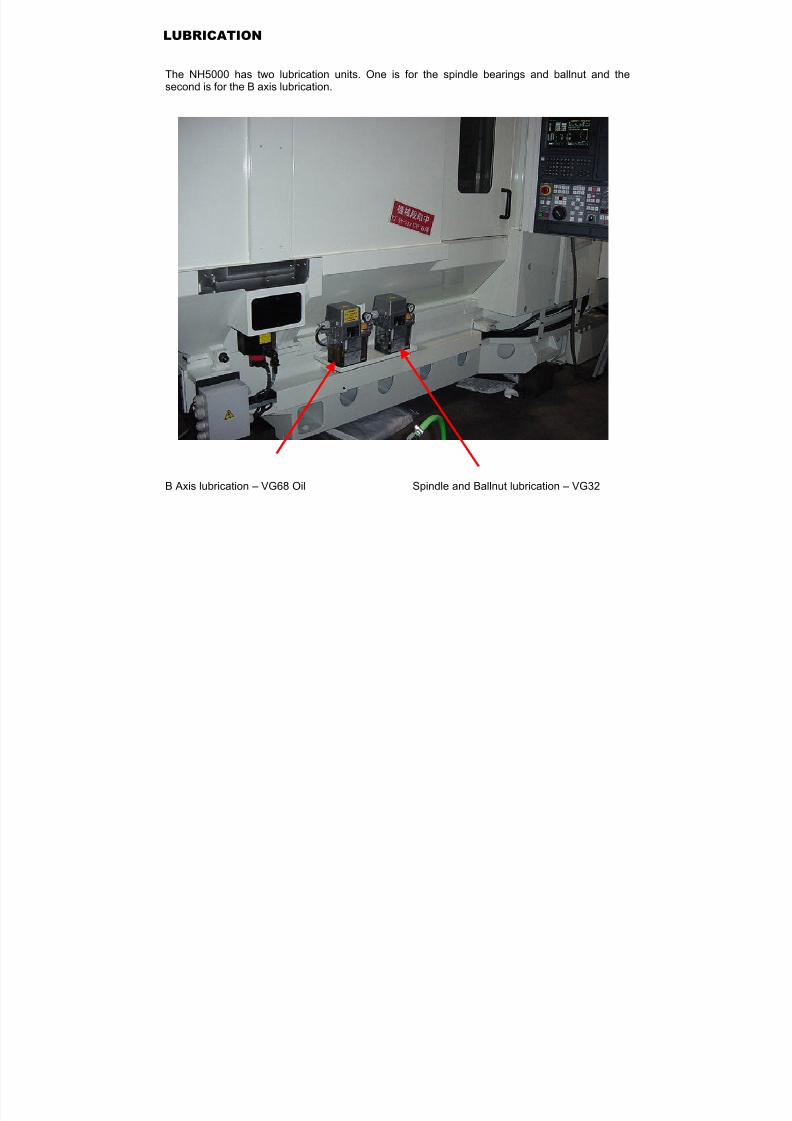
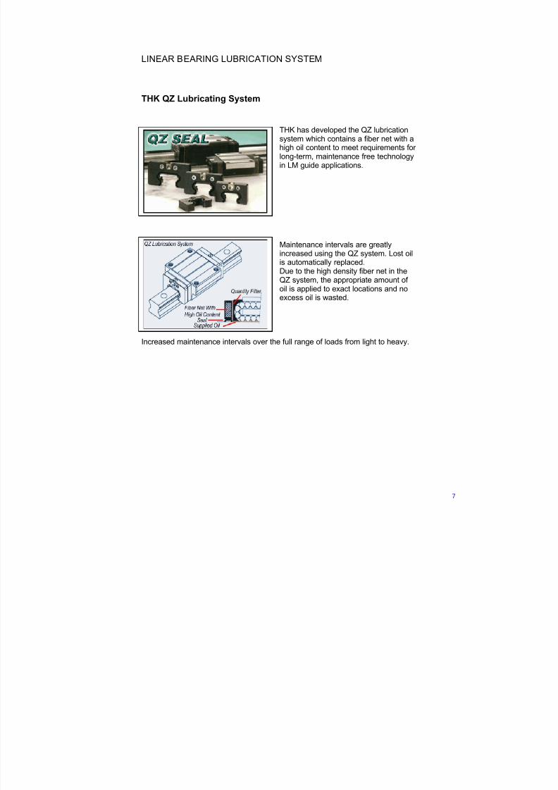
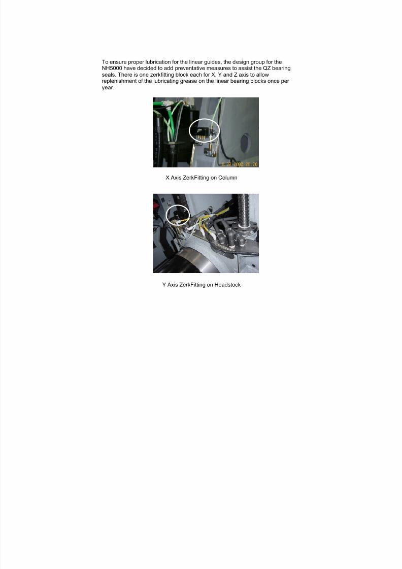
LINEAR BEARING LUBRICATION SYSTEM
THK QZ Lubricating System
THK has developed the QZ lubricationsystem which contains a fiber net with ahigh oil content to meet requirements for long-term, maintenance free technologyin LM guide applications.
Maintenance intervals are greatlyincreased using the QZ system. Lost oilis automatically replaced.Due to the high density fiber net in theQZ system, the appropriate amount of
oil is applied to exact locations and noexcess oil is wasted.
Increased maintenance intervals over the full range of loads from light to heavy.
7/21/2019 MORISEIKI MAINTENANCE CLASS
http://slidepdf.com/reader/full/moriseiki-maintenance-class 129/409

7/21/2019 MORISEIKI MAINTENANCE CLASS
http://slidepdf.com/reader/full/moriseiki-maintenance-class 130/409
7/21/2019 MORISEIKI MAINTENANCE CLASS
http://slidepdf.com/reader/full/moriseiki-maintenance-class 131/409
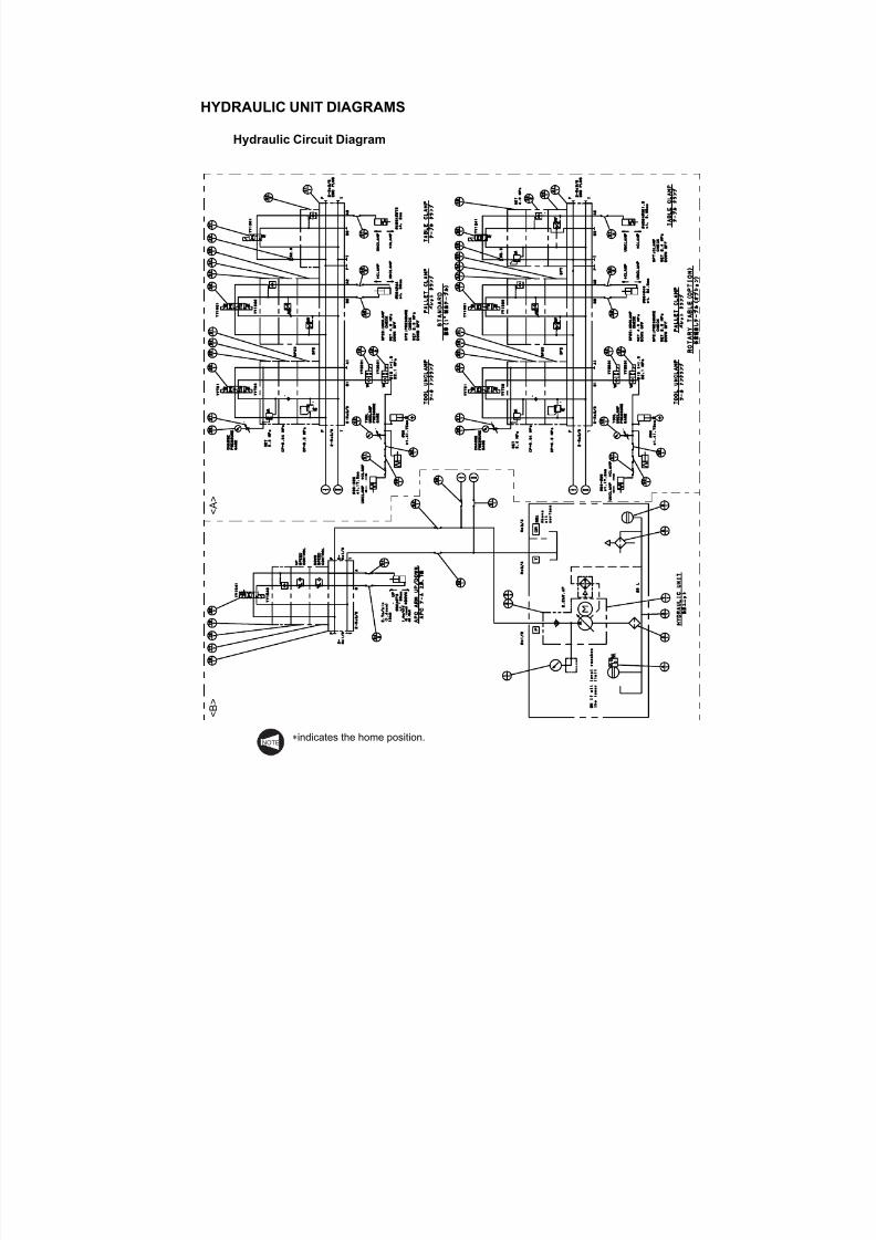
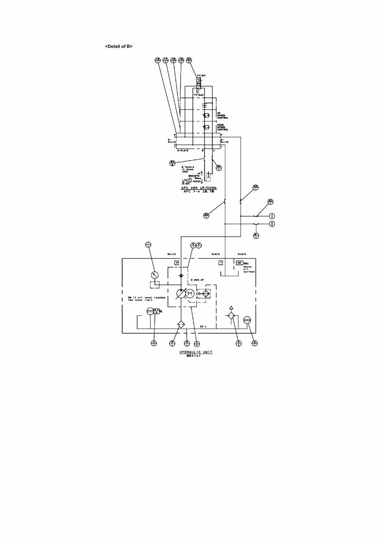
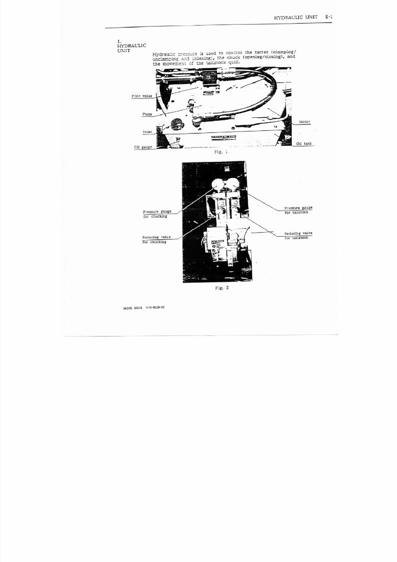
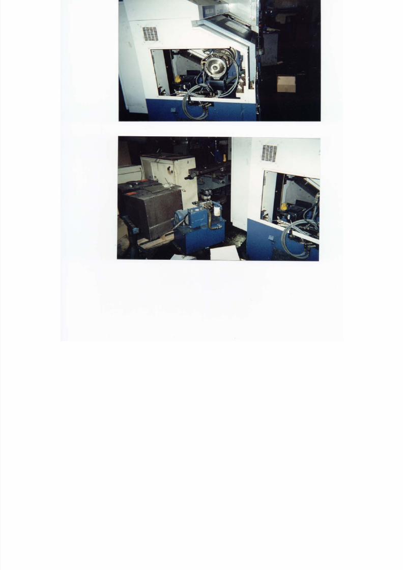
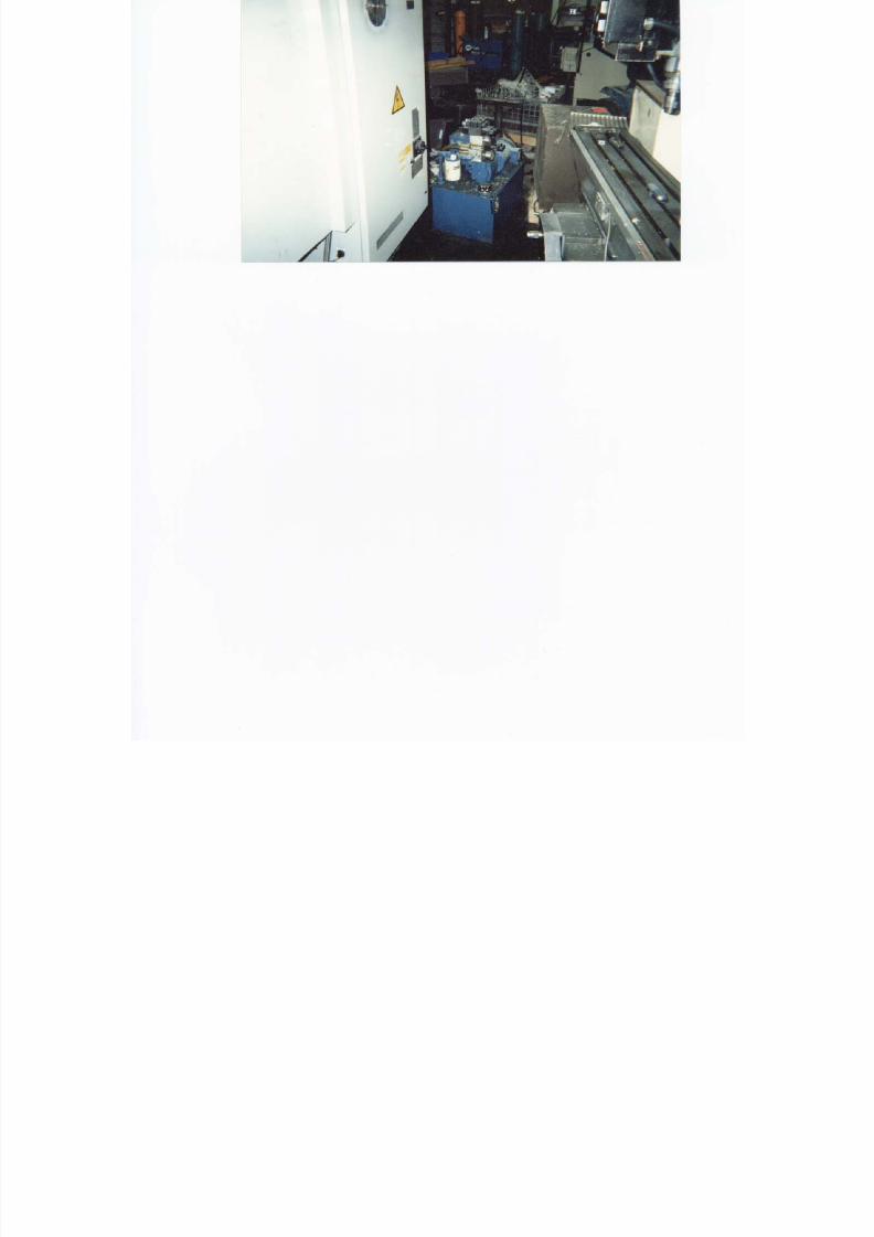
HYDRAULIC SYSTEM
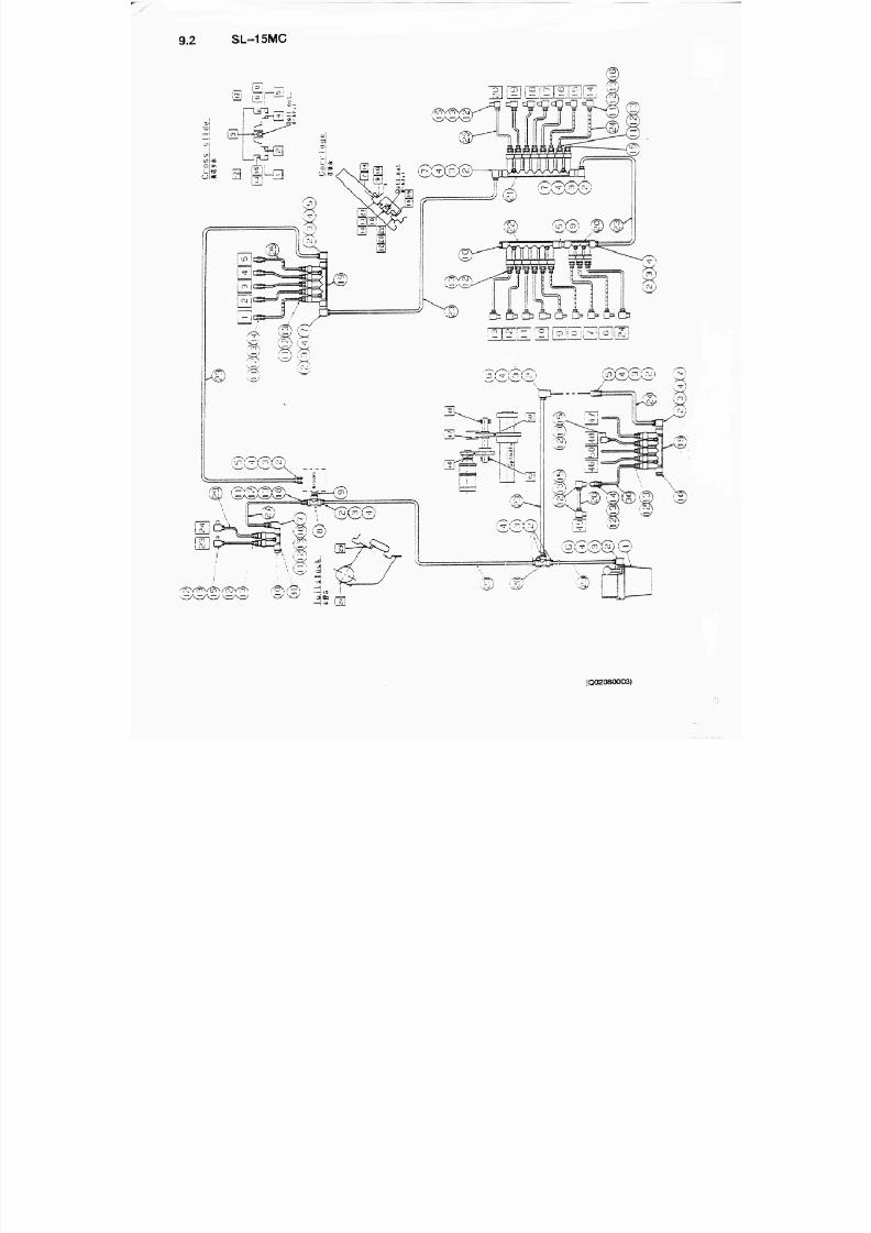
An overview of the HYDRAULIC SYSTEM is presented below.
The hydraulic system comprises the hydraulic unit, the valve units, the hydraulic devices, and thepiping.
When the power is turned on, the hydraulic motor starts and the pump draws hydraulic fluid.
The hydraulic fluid that flows out of the pump is supplied through the piping to the valve units.
The valve units reduce the pressure of the hydraulic fluid and determine its course, and the
hydraulic devices are actuated by the hydraulic fluid.
The hydraulic fluid is returned to the tank through the tank port.
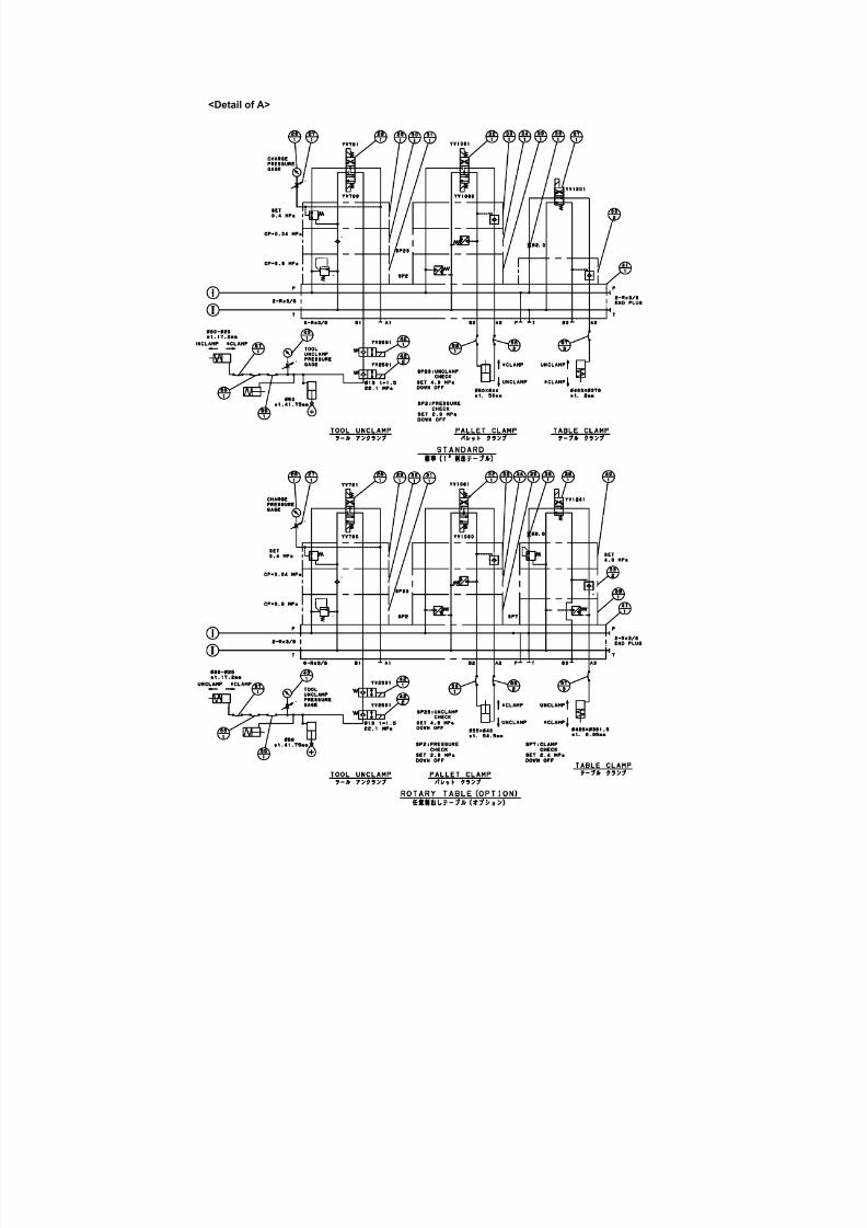
Hydraulically-operated Actuators
The hydraulically-operated actuators are indicated below:
(1) Pallet clamp/unclamp
(2) Table clamp/unclamp
(3) APC arm up/down
(4) Pre-load changeover (20000 min1 specification)
(5) Fixture clamp/unclamp inside setup station (auto-coupler and 2-/3-station APC specifications)
(6) Fixture clamp/clamp inside machine (auto-coupler and 2-/3-station APC specifications)
7/21/2019 MORISEIKI MAINTENANCE CLASS
http://slidepdf.com/reader/full/moriseiki-maintenance-class 132/409
7/21/2019 MORISEIKI MAINTENANCE CLASS
http://slidepdf.com/reader/full/moriseiki-maintenance-class 133/409
7/21/2019 MORISEIKI MAINTENANCE CLASS
http://slidepdf.com/reader/full/moriseiki-maintenance-class 134/409
<Detail of B>
7/21/2019 MORISEIKI MAINTENANCE CLASS
http://slidepdf.com/reader/full/moriseiki-maintenance-class 135/409
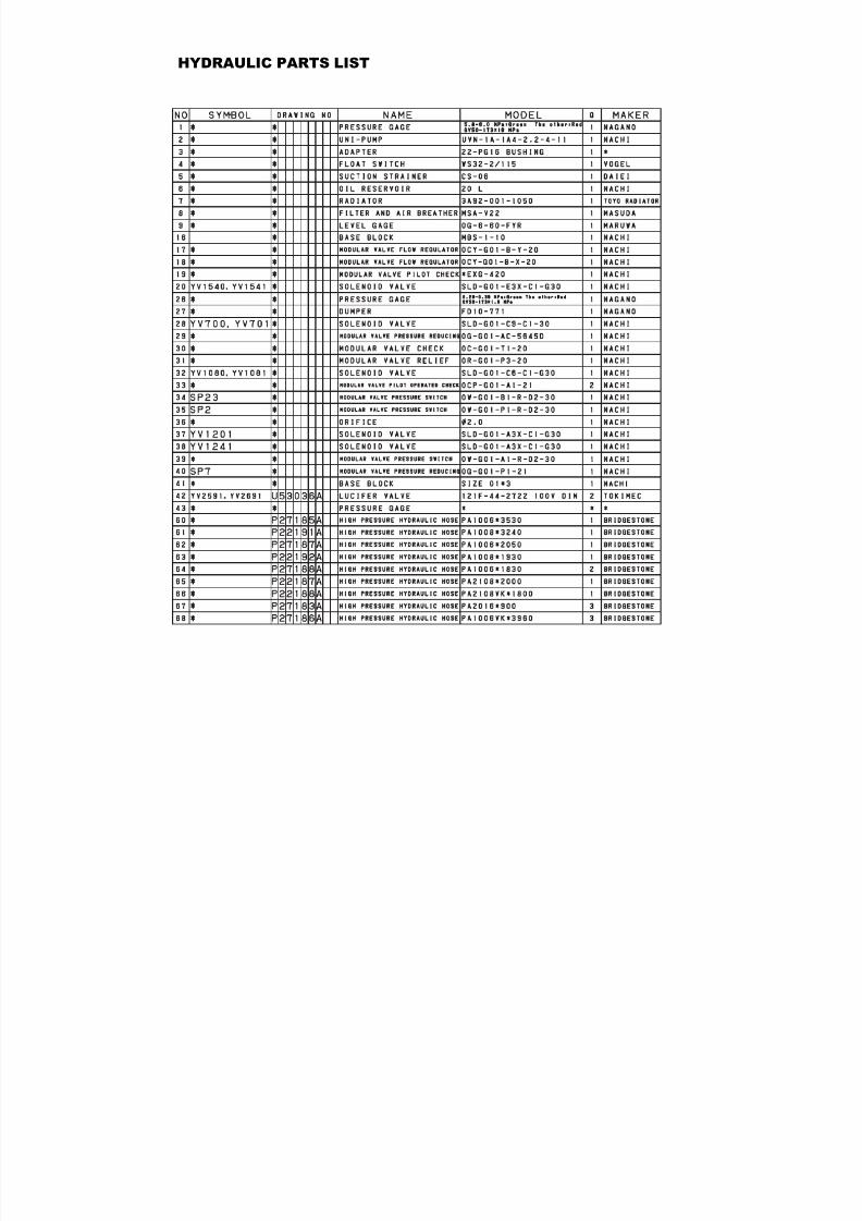
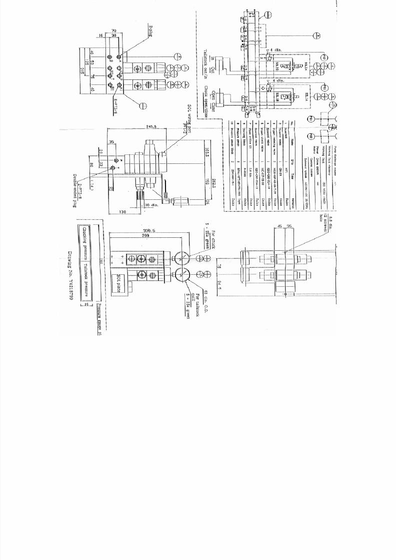
HYDRAULIC PARTS LIST
7/21/2019 MORISEIKI MAINTENANCE CLASS
http://slidepdf.com/reader/full/moriseiki-maintenance-class 136/409
7/21/2019 MORISEIKI MAINTENANCE CLASS
http://slidepdf.com/reader/full/moriseiki-maintenance-class 137/409
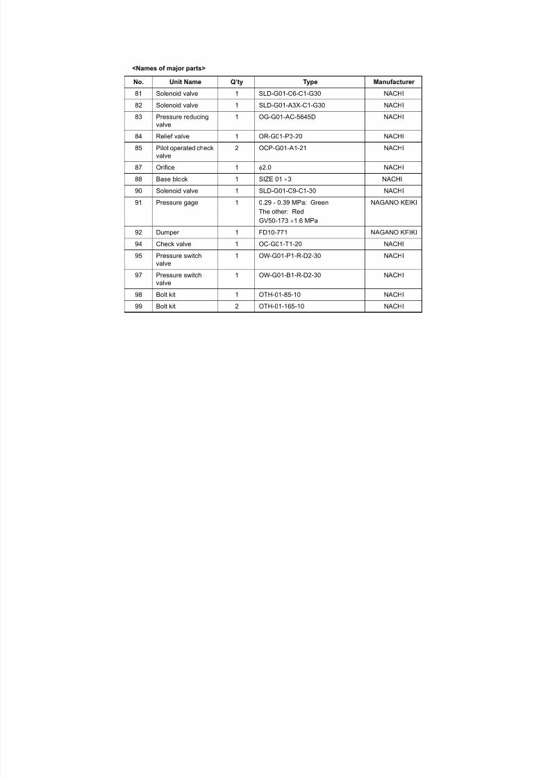
<Names of major parts>
No. Unit Name Q’ty Type Manufacturer
81 Solenoid valve 1 SLD-G01-C6-C1-G30 NACHI82 Solenoid valve 1 SLD-G01-A3X-C1-G30 NACHI
83 Pressure reducingvalve
1 OG-G01-AC-5645D NACHI
84 Relief valve 1 OR-G01-P3-20 NACHI
85 Pilot operated checkvalve
2 OCP-G01-A1-21 NACHI
87 Orifice 1 φ2.0 NACHI
88 Base block 1 SIZE 01 × 3 NACHI
90 Solenoid valve 1 SLD-G01-C9-C1-30 NACHI91 Pressure gage 1 0.29 - 0.39 MPa: Green
The other: Red
GV50-173 × 1.6 MPa
NAGANO KEIKI
92 Dumper 1 FD10-771 NAGANO KEIKI
94 Check valve 1 OC-G01-T1-20 NACHI
95 Pressure switchvalve
1 OW-G01-P1-R-D2-30 NACHI
97 Pressure switchvalve
1 OW-G01-B1-R-D2-30 NACHI
98 Bolt kit 1 OTH-01-85-10 NACHI
99 Bolt kit 2 OTH-01-165-10 NACHI
7/21/2019 MORISEIKI MAINTENANCE CLASS
http://slidepdf.com/reader/full/moriseiki-maintenance-class 138/409
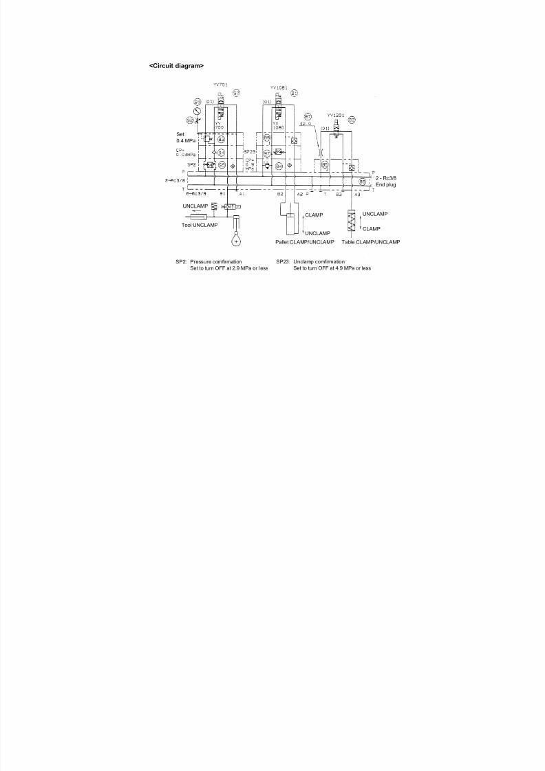
<Circuit diagram>
2 - Rc3/8End plug
Set0.4 MPa
Tool UNCLAMP
UNCLAMP
Pallet CLAMP/UNCLAMP Table CLAMP/UNCLAMP
UNCLAMP
CLAMP UNCLAMP
CLAMP
SP23: Unclamp comfirmationSet to turn OFF at 4.9 MPa or less
SP2: Pressure comfirmationSet to turn OFF at 2.9 MPa or less

7/21/2019 MORISEIKI MAINTENANCE CLASS
http://slidepdf.com/reader/full/moriseiki-maintenance-class 139/409
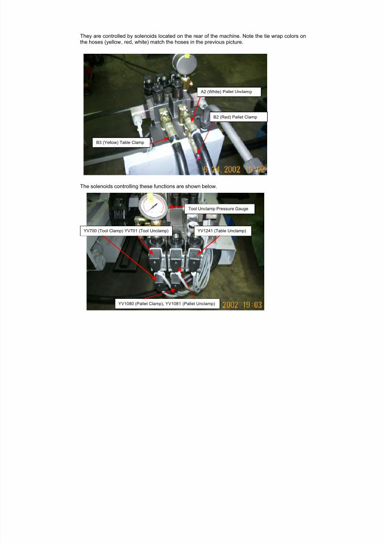
The picture below shows what each line is for that is located on top of the headstock casting.
Spindle Oil InCoolant Motor Oil In
Spindle Taper Air Blow
Tool Tip Air Blow
Spindle Face Air Blow
Oil Shot 1
Motor Oil Out
Spindle Oil Out Oil Hole Drill Coolant
Spindle Taper Air Blow
HYDRAULICS TO HEADSTOCK
7/21/2019 MORISEIKI MAINTENANCE CLASS
http://slidepdf.com/reader/full/moriseiki-maintenance-class 140/409
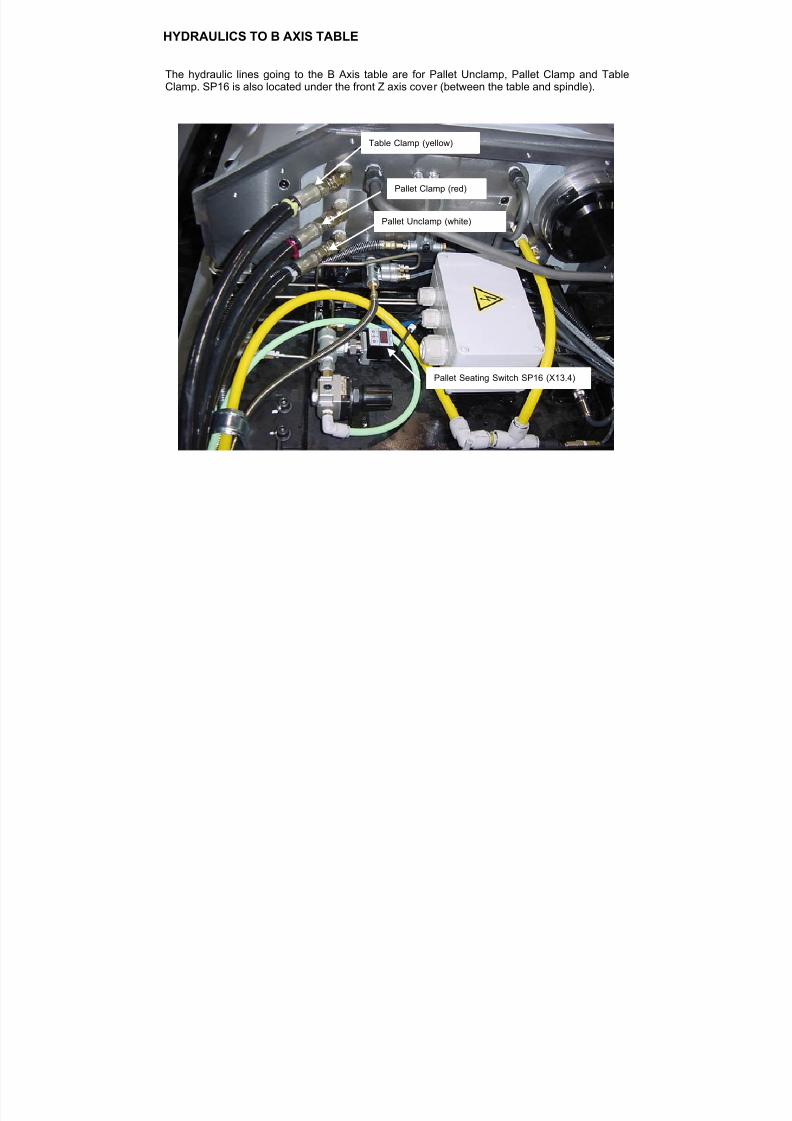
The hydraulic lines going to the B Axis table are for Pallet Unclamp, Pallet Clamp and TableClamp. SP16 is also located under the front Z axis cover (between the table and spindle).
Table Clamp (yellow)
Pallet Clamp (red)
Pallet Unclamp (white)
Pallet Seating Switch SP16 (X13.4)
HYDRAULICS TO B AXIS TABLE
7/21/2019 MORISEIKI MAINTENANCE CLASS
http://slidepdf.com/reader/full/moriseiki-maintenance-class 141/409
7/21/2019 MORISEIKI MAINTENANCE CLASS
http://slidepdf.com/reader/full/moriseiki-maintenance-class 142/409
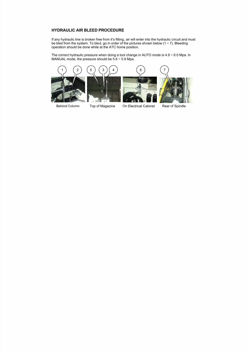
HYDRAULIC AIR BLEED PROCEDURE
If any hydraulic line is broken free from it’s fitting, air will enter into the hydraulic circuit and must
be bled from the system. To bled, go in order of the pictures shown below (1 ~ 7). Bleedingoperation should be done while at the ATC home position.
The correct hydraulic pressure when doing a tool change in AUTO mode is 4.9 ~ 6.0 Mpa. InMANUAL mode, the pressure should be 5.6 ~ 5.9 Mpa.
Behind Column Top of Magazine On Electrical Cabinet Rear of Spindle
1 5
64 72 3
7/21/2019 MORISEIKI MAINTENANCE CLASS
http://slidepdf.com/reader/full/moriseiki-maintenance-class 143/409
7/21/2019 MORISEIKI MAINTENANCE CLASS
http://slidepdf.com/reader/full/moriseiki-maintenance-class 144/409
7/21/2019 MORISEIKI MAINTENANCE CLASS
http://slidepdf.com/reader/full/moriseiki-maintenance-class 145/409
7/21/2019 MORISEIKI MAINTENANCE CLASS
http://slidepdf.com/reader/full/moriseiki-maintenance-class 146/409
7/21/2019 MORISEIKI MAINTENANCE CLASS
http://slidepdf.com/reader/full/moriseiki-maintenance-class 147/409
7/21/2019 MORISEIKI MAINTENANCE CLASS
http://slidepdf.com/reader/full/moriseiki-maintenance-class 148/409
7/21/2019 MORISEIKI MAINTENANCE CLASS
http://slidepdf.com/reader/full/moriseiki-maintenance-class 149/409
7/21/2019 MORISEIKI MAINTENANCE CLASS
http://slidepdf.com/reader/full/moriseiki-maintenance-class 150/409
7/21/2019 MORISEIKI MAINTENANCE CLASS
http://slidepdf.com/reader/full/moriseiki-maintenance-class 151/409
7/21/2019 MORISEIKI MAINTENANCE CLASS
http://slidepdf.com/reader/full/moriseiki-maintenance-class 152/409

7/21/2019 MORISEIKI MAINTENANCE CLASS
http://slidepdf.com/reader/full/moriseiki-maintenance-class 153/409
7/21/2019 MORISEIKI MAINTENANCE CLASS
http://slidepdf.com/reader/full/moriseiki-maintenance-class 154/409
7/21/2019 MORISEIKI MAINTENANCE CLASS
http://slidepdf.com/reader/full/moriseiki-maintenance-class 155/409
7/21/2019 MORISEIKI MAINTENANCE CLASS
http://slidepdf.com/reader/full/moriseiki-maintenance-class 156/409
7/21/2019 MORISEIKI MAINTENANCE CLASS
http://slidepdf.com/reader/full/moriseiki-maintenance-class 157/409
7/21/2019 MORISEIKI MAINTENANCE CLASS
http://slidepdf.com/reader/full/moriseiki-maintenance-class 158/409
7/21/2019 MORISEIKI MAINTENANCE CLASS
http://slidepdf.com/reader/full/moriseiki-maintenance-class 159/409
7/21/2019 MORISEIKI MAINTENANCE CLASS
http://slidepdf.com/reader/full/moriseiki-maintenance-class 160/409

7/21/2019 MORISEIKI MAINTENANCE CLASS
http://slidepdf.com/reader/full/moriseiki-maintenance-class 161/409
7/21/2019 MORISEIKI MAINTENANCE CLASS
http://slidepdf.com/reader/full/moriseiki-maintenance-class 162/409
7/21/2019 MORISEIKI MAINTENANCE CLASS
http://slidepdf.com/reader/full/moriseiki-maintenance-class 163/409
7/21/2019 MORISEIKI MAINTENANCE CLASS
http://slidepdf.com/reader/full/moriseiki-maintenance-class 164/409
7/21/2019 MORISEIKI MAINTENANCE CLASS
http://slidepdf.com/reader/full/moriseiki-maintenance-class 165/409
7/21/2019 MORISEIKI MAINTENANCE CLASS
http://slidepdf.com/reader/full/moriseiki-maintenance-class 166/409
7/21/2019 MORISEIKI MAINTENANCE CLASS
http://slidepdf.com/reader/full/moriseiki-maintenance-class 167/409
7/21/2019 MORISEIKI MAINTENANCE CLASS
http://slidepdf.com/reader/full/moriseiki-maintenance-class 168/409
7/21/2019 MORISEIKI MAINTENANCE CLASS
http://slidepdf.com/reader/full/moriseiki-maintenance-class 169/409
7/21/2019 MORISEIKI MAINTENANCE CLASS
http://slidepdf.com/reader/full/moriseiki-maintenance-class 170/409
7/21/2019 MORISEIKI MAINTENANCE CLASS
http://slidepdf.com/reader/full/moriseiki-maintenance-class 171/409
7/21/2019 MORISEIKI MAINTENANCE CLASS
http://slidepdf.com/reader/full/moriseiki-maintenance-class 172/409
7/21/2019 MORISEIKI MAINTENANCE CLASS
http://slidepdf.com/reader/full/moriseiki-maintenance-class 173/409
7/21/2019 MORISEIKI MAINTENANCE CLASS
http://slidepdf.com/reader/full/moriseiki-maintenance-class 174/409
7/21/2019 MORISEIKI MAINTENANCE CLASS
http://slidepdf.com/reader/full/moriseiki-maintenance-class 175/409
7/21/2019 MORISEIKI MAINTENANCE CLASS
http://slidepdf.com/reader/full/moriseiki-maintenance-class 176/409
7/21/2019 MORISEIKI MAINTENANCE CLASS
http://slidepdf.com/reader/full/moriseiki-maintenance-class 177/409
7/21/2019 MORISEIKI MAINTENANCE CLASS
http://slidepdf.com/reader/full/moriseiki-maintenance-class 178/409
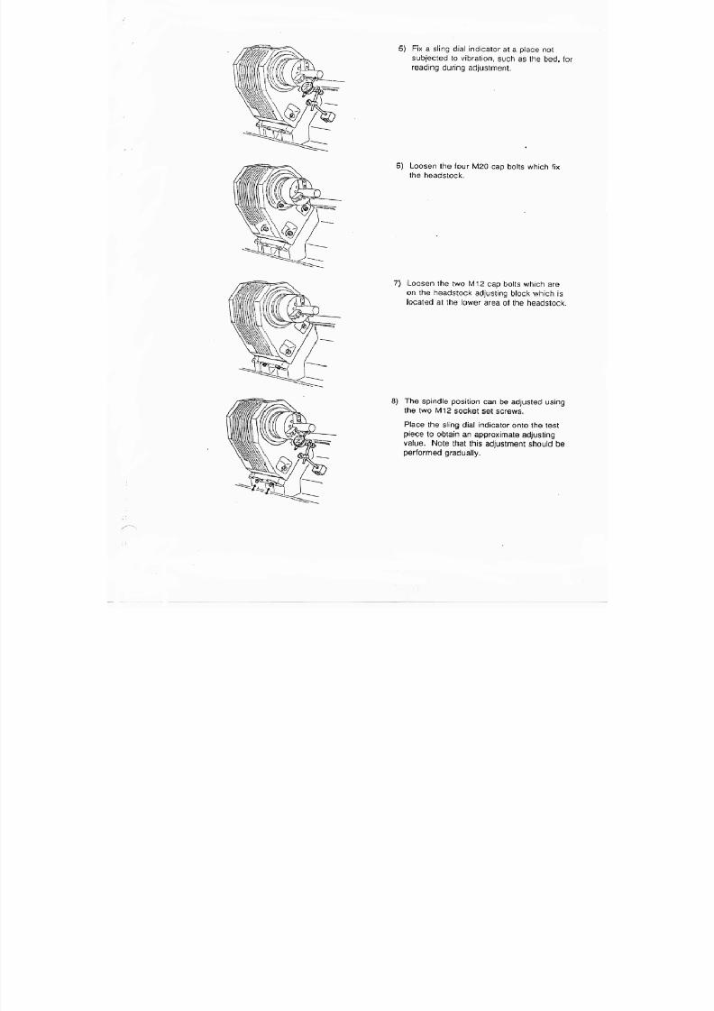
7/21/2019 MORISEIKI MAINTENANCE CLASS
http://slidepdf.com/reader/full/moriseiki-maintenance-class 179/409
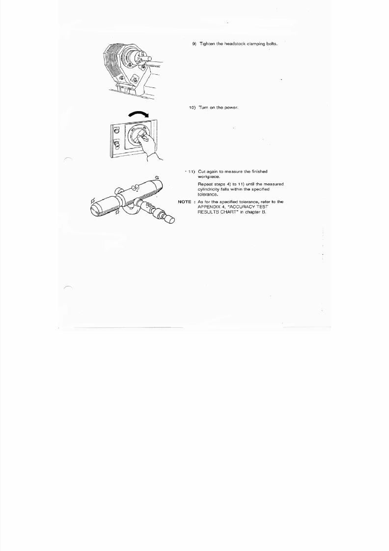
7/21/2019 MORISEIKI MAINTENANCE CLASS
http://slidepdf.com/reader/full/moriseiki-maintenance-class 180/409

7/21/2019 MORISEIKI MAINTENANCE CLASS
http://slidepdf.com/reader/full/moriseiki-maintenance-class 181/409
1
2
3
4
5
6
7
8
9
10
11
12
12
15
16
17
A
Detail Drawing A
13
18
19
20
21
22
23
32
33
27
28
Detail Drawing B
24
26
25
37
38
Y
W
U
Y
WW
W
Y
Z
W;Applied Oil(Daphne Mechanic Oil 32)
Y:Applied Anaerobic Adhesive & Sealant (Three Bond 1344)Z ; Interference 0.01mm
U ; Pushing force 14700N(1500kgf)
35
14
39
MAS
CATDIN
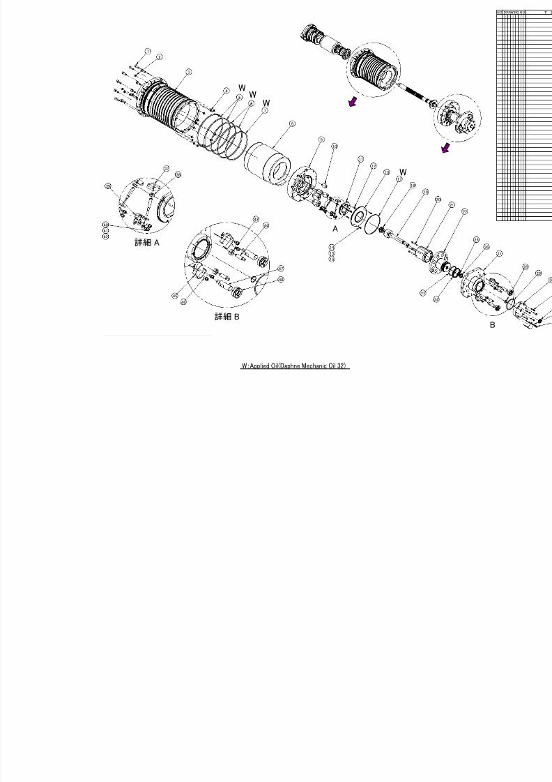
7/21/2019 MORISEIKI MAINTENANCE CLASS
http://slidepdf.com/reader/full/moriseiki-maintenance-class 182/409
A
詳細 A
詳細 B
1
2
3
4
5
6
7
8
9
10
11
12
13
17
18
19
20
23
24
14
37
38
39
40
43
44
45
46
47
48
15
16
41
42
W;Applied Oil(Daphne Mechanic Oil 32)
W
WW
W
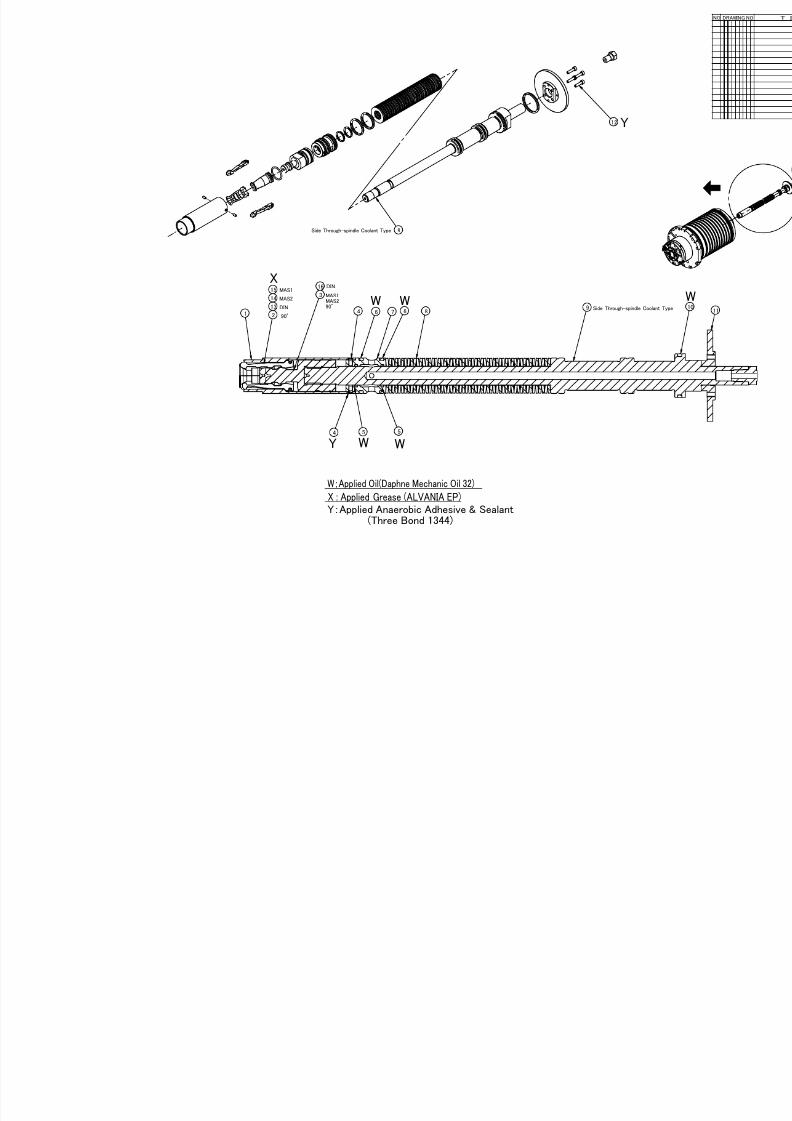
7/21/2019 MORISEIKI MAINTENANCE CLASS
http://slidepdf.com/reader/full/moriseiki-maintenance-class 183/409
2
5 54
12
9
MAS1
MAS2
DIN
90°1
3
4 6 7 6 8913
14
15
X : Applied Grease (ALVANIA EP)
W;Applied Oil(Daphne Mechanic Oil 32)
Y:Applied Anaerobic Adhesive & Sealant (Three Bond 1344)
X
W W
W WY
Side Through-spindle Coolant Type
Y
MAS1MAS290°
16 DIN
Side Through-spindle

7/21/2019 MORISEIKI MAINTENANCE CLASS
http://slidepdf.com/reader/full/moriseiki-maintenance-class 184/409
THE SPINDLE and DRAWBAR
The spindle on the NH5000 will be standard 14,000 min-1, with an optional20,000 min-1 offered. It is powered by a 22/18.5 kW (30 HP) DDS spindle motor,
which allows tapping at 6,000 min-1. The starting torque on the spindle is 221N•m, which will reach 14,000min-1 in 1.4 seconds and only take 1.15 seconds toreturn to a complete stop.
The NH5000 will be offered with the standard BT-40 spindle and offer an optionalKM style package.
KM Spindle
KM Drawbar
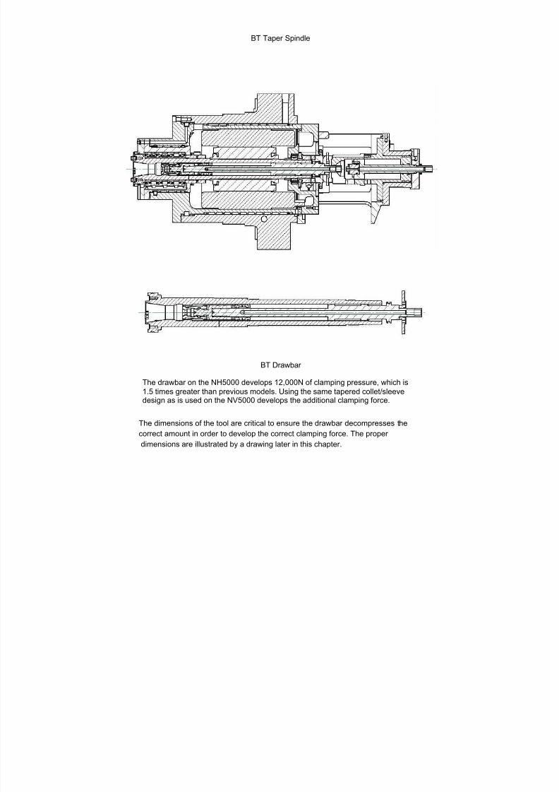
7/21/2019 MORISEIKI MAINTENANCE CLASS
http://slidepdf.com/reader/full/moriseiki-maintenance-class 185/409
BT Taper Spindle
BT Drawbar
The drawbar on the NH5000 develops 12,000N of clamping pressure, which is
1.5 times greater than previous models. Using the same tapered collet/sleevedesign as is used on the NV5000 develops the additional clamping force.
The dimensions of the tool are critical to ensure the drawbar decompresses the
correct amount in order to develop the correct clamping force. The proper
dimensions are illustrated by a drawing later in this chapter.
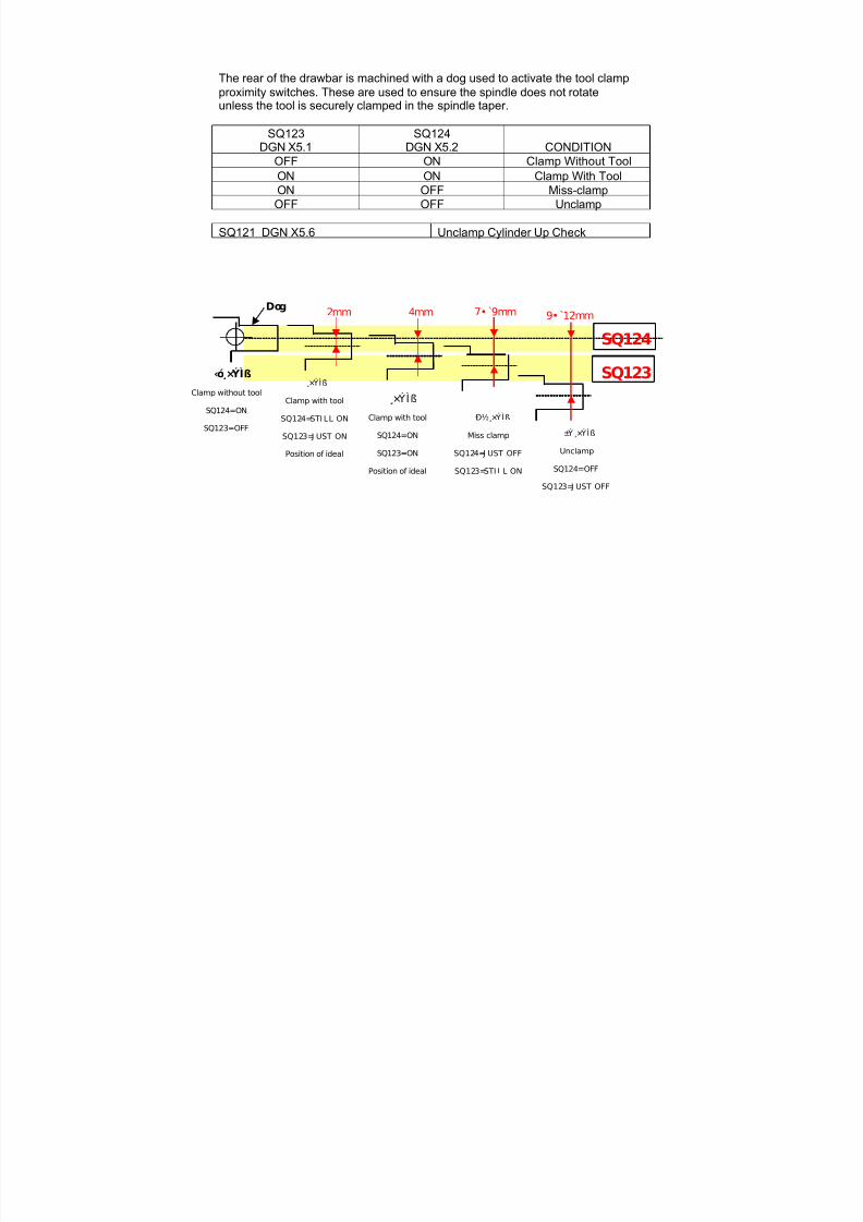
7/21/2019 MORISEIKI MAINTENANCE CLASS
http://slidepdf.com/reader/full/moriseiki-maintenance-class 186/409
The rear of the drawbar is machined with a dog used to activate the tool clampproximity switches. These are used to ensure the spindle does not rotateunless the tool is securely clamped in the spindle taper.
SQ123
DGN X5.1
SQ124
DGN X5.2 CONDITIONOFF ON Clamp Without ToolON ON Clamp With ToolON OFF Miss-clampOFF OFF Unclamp
SQ121 DGN X5.6 Unclamp Cylinder Up Check
SQ124
SQ123
Dog
‹ó ×ÝÌß
Clamp without tool
SQ124=ON
SQ123=OFF
×ÝÌß
Clamp with tool
SQ124=STI LL ON
SQ123=J UST ON
Position of ideal
н ×ÝÌß
Miss clamp
SQ124=J UST OFF
SQ123=STI LL ON
±Ý ×ÝÌß
UnclampSQ124=OFF
SQ123=J UST OFF
2mm 7• 9mm 9• 12mm4mm
×ÝÌß
Clamp with tool
SQ124=ON
SQ123=ON
Position of ideal
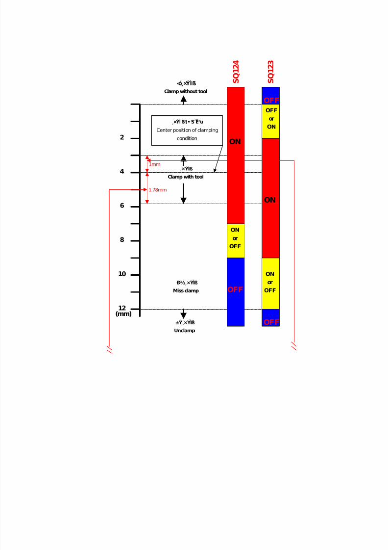
7/21/2019 MORISEIKI MAINTENANCE CLASS
http://slidepdf.com/reader/full/moriseiki-maintenance-class 187/409
2
4
6
8
10
12(mm)
ON
OFF
OFF
OFF
S Q 1 2
4
S Q 1 2
3
ON
or
OFF
ONor
OFF
OFF
or
ON
‹ó×ÝÌß
Clamp without tool
¸×ÝÌß
Clamp with tool
н¸×ÝÌß
Miss clamp
±Ý ×ÝÌß
Unclamp
×ÝÌß’†S Ê’u
Center position of clamping
condition
1mm
1.78mm
ON
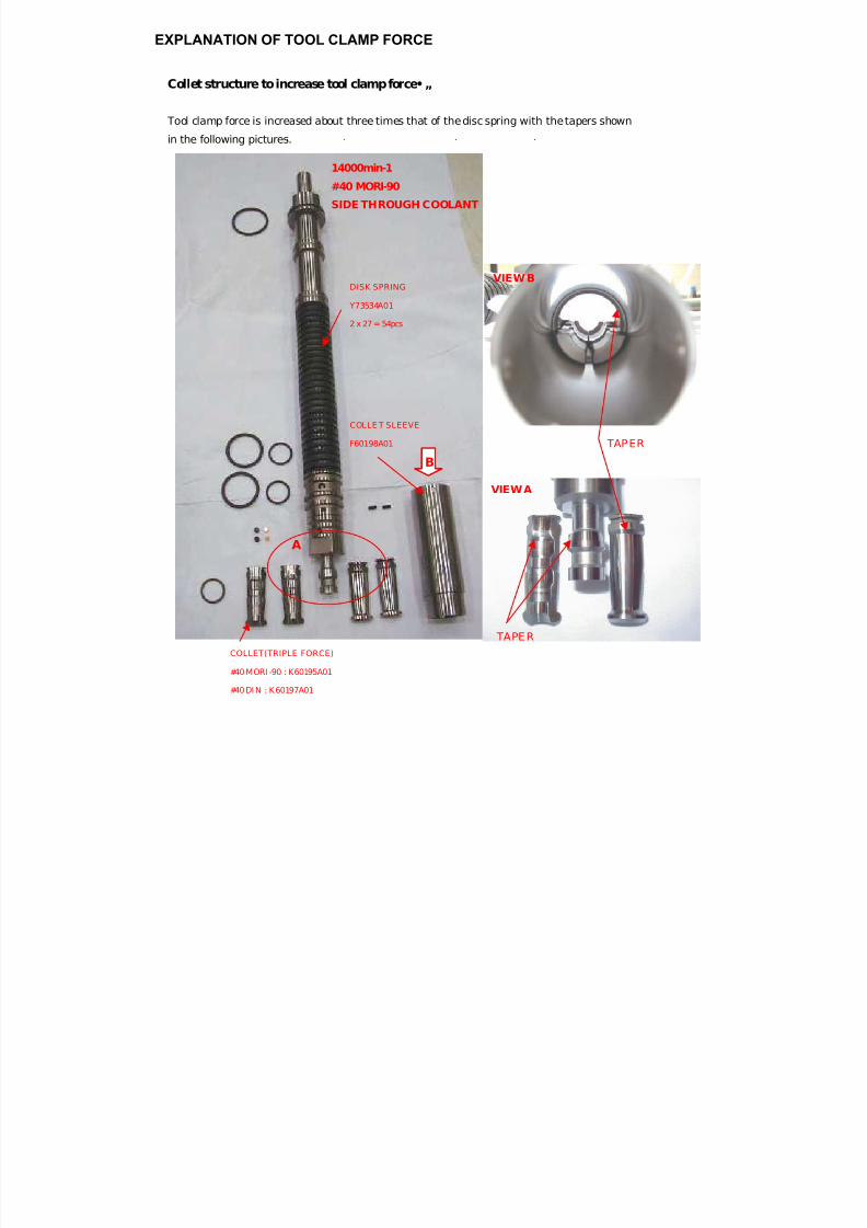
7/21/2019 MORISEIKI MAINTENANCE CLASS
http://slidepdf.com/reader/full/moriseiki-maintenance-class 188/409
Collet structure to increase tool clamp force•„
Tool clamp force is increased about three times that of the disc spring with the tapers shown
in the following pictures.
14000min-1
#40 MORI-90
SIDE THROUGH COOLANT
DISK SPRING
Y73534A01
2 x 27 = 54pcs
COLLET(TRIPLE FORCE)
#40 MORI-90 : K60195A01
#40 DI N : K60197A01
COLLE T SLEEVE
F60198A01
A
B
VIEW B
VIEW A
TAPER
TAPER
EXPLANATION OF TOOL CLAMP FORCE
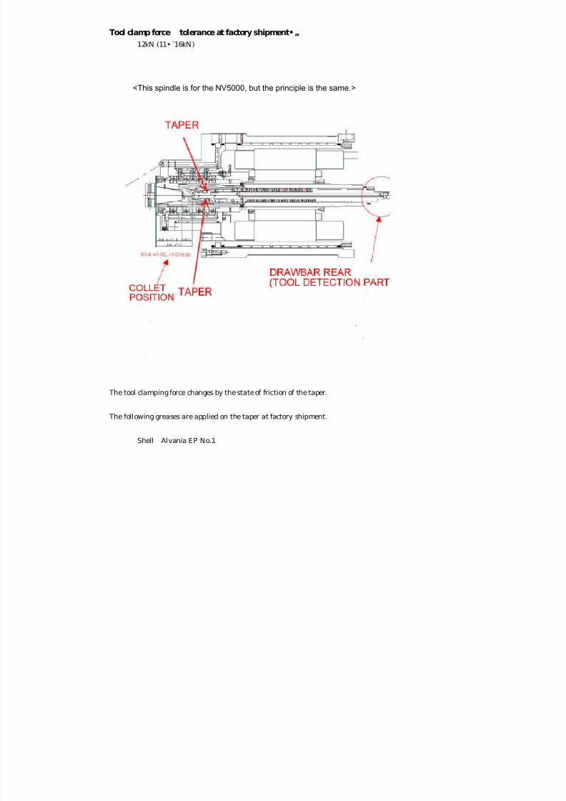
7/21/2019 MORISEIKI MAINTENANCE CLASS
http://slidepdf.com/reader/full/moriseiki-maintenance-class 189/409
Tool clamp force tolerance at factory shipment•„
12kN (11• 16kN)
KELCH D-73614
The tool clamping force changes by the state of friction of the taper.
The following greases are applied on the taper at factory shipment.
Shell Alvania EP No.1
<This spindle is for the NV5000, but the principle is the same.>
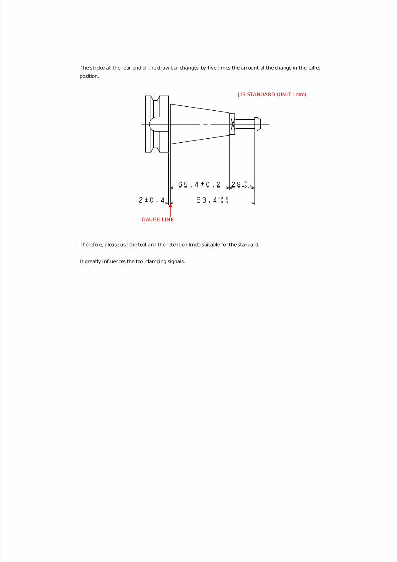
7/21/2019 MORISEIKI MAINTENANCE CLASS
http://slidepdf.com/reader/full/moriseiki-maintenance-class 190/409
The stroke at the rear end of the draw bar changes by five times the amount of the change in the colletposition.
Therefore, please use the tool and the retention knob suitable for the standard.
I t greatly influences the tool clamping signals.
GAUGE LINE
J IS STANDARD (UNIT : mm)

7/21/2019 MORISEIKI MAINTENANCE CLASS
http://slidepdf.com/reader/full/moriseiki-maintenance-class 191/409
SPINDLE SPEED OUTPUT DIAGRAM
* Spindle speed outputs are expressed in 15 min. rating for low-speed range winding
and in 30 min. rating for high-speed range winding.
Motor Specifications
Output 22/18.5 kWRated time 15 min, 30 min∗/Continuous
Spindle speed 14000 min−1 (max.)Manufacturer FANUC
NOTE
7/21/2019 MORISEIKI MAINTENANCE CLASS
http://slidepdf.com/reader/full/moriseiki-maintenance-class 192/409
to perform orientation command.
To move to reverse rotation, input value in - direction.
standard value less than 0.1mm (parallelism measured at )
ADJUSTING SPINDLE ORIENTATION
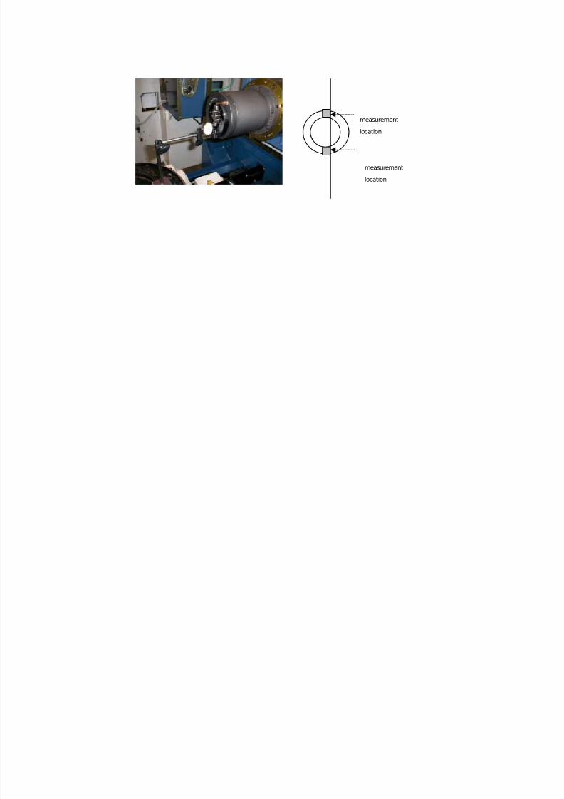
7/21/2019 MORISEIKI MAINTENANCE CLASS
http://slidepdf.com/reader/full/moriseiki-maintenance-class 193/409
measurement
location
measurement
location
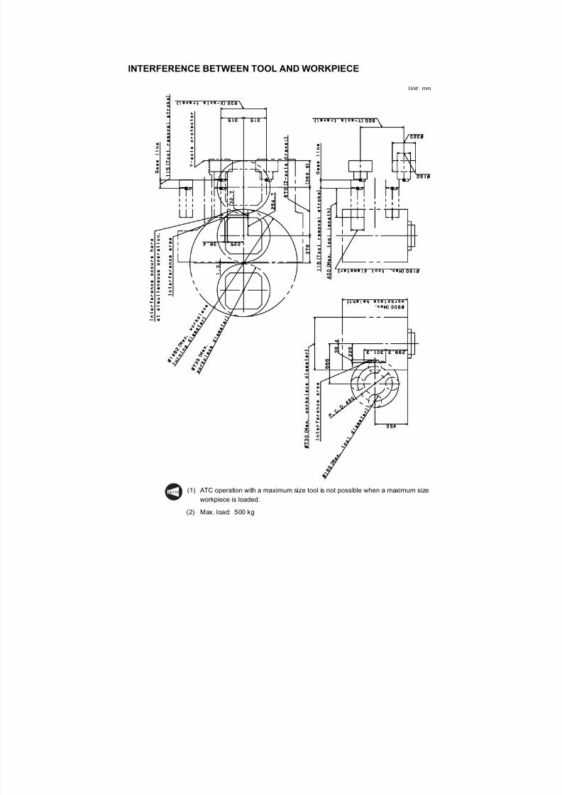
7/21/2019 MORISEIKI MAINTENANCE CLASS
http://slidepdf.com/reader/full/moriseiki-maintenance-class 194/409
INTERFERENCE BETWEEN TOOL AND WORKPIECE
Unit: mm
(1) ATC operation with a maximum size tool is not possible when a maximum sizeworkpiece is loaded.
( )
NOTE
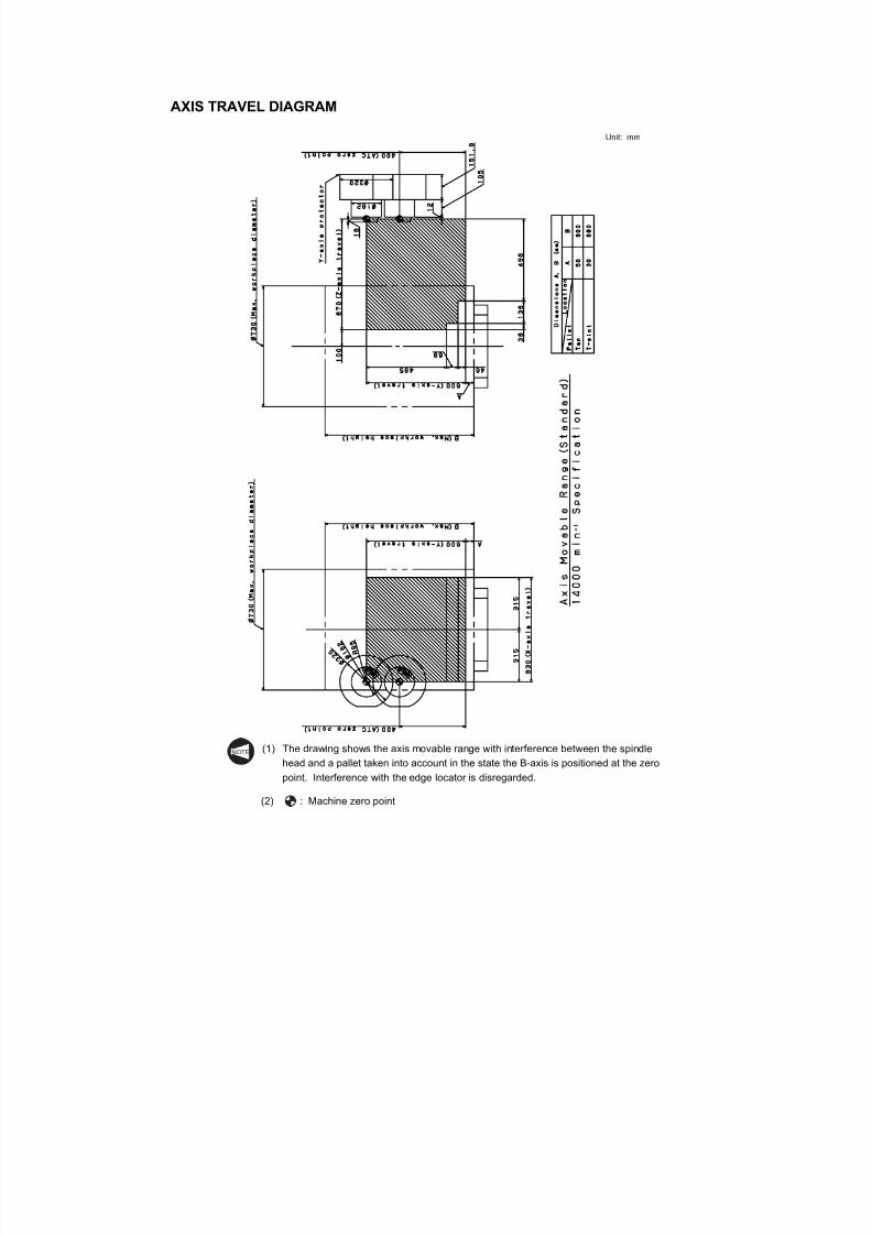
7/21/2019 MORISEIKI MAINTENANCE CLASS
http://slidepdf.com/reader/full/moriseiki-maintenance-class 195/409
AXIS TRAVEL DIAGRAM
Unit: mm
(1) The drawing shows the axis movable range with interference between the spindle
head and a pallet taken into account in the state the B-axis is positioned at the zeropoint. Interference with the edge locator is disregarded.
NOTE
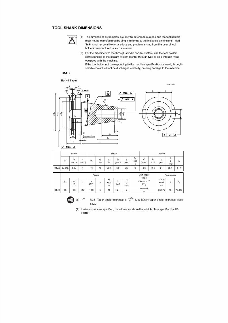
7/21/2019 MORISEIKI MAINTENANCE CLASS
http://slidepdf.com/reader/full/moriseiki-maintenance-class 196/409
TOOL SHANK DIMENSIONS
(1) The dimensions given below are only for reference purpose and the tool holders
must not be manufactured by simply referring to the indicated dimensions. MoriSeiki is not responsible for any loss and problem arising from the user of tool
holders manufactured in such a manner.
(2) For the machine with the through-spindle coolant system, use the tool holders
corresponding to the coolant system (center-through type or side-through type)
equipped with the machine.
If the tool holder not corresponding to the machine specifications is used, through-
spindle coolant will not be discharged correctly, causing damage to the machine.
MAS
No. 40 Taper
Unit: mm
(1) n*1 7/24 Taper angle tolerance is (JIS B0614 taper angle tolerance class AT4).
Shank Screw Tenon
D1 l 1±0.15
r (max.)
d1 d2H8
g6H
l2(min.)
l3(min.)
l 4
+0.5
0
C(max.)
bH12
l5(min.)
t
0
−0.2
w
BT40 44.450 65.4 1 19 17 M16 30 43 9 0.5 16.1 21 22.6 0.12
Flange 7/24 Taper
angle
tolerance *1
AT D
References
D4D5
h8f
v
±0.1x
x1
+0.1
0
y
±0.4
y4
0
−0.4
Dia. at
small
end
d D6
BT40 53 63 25 16.6 5 10 2 2+0.0041
025.375 10 75.679
CAUTION
30° −15° 30°0−15°
φ D 6
φ D 5
φ D 4 φ
φ d 2
φ d 1
d
l5
v
xx1
f
y
y1
Gage surface
l1
l3
l2
l4
r
g
t t
b
°
NOTE
+AT4 0
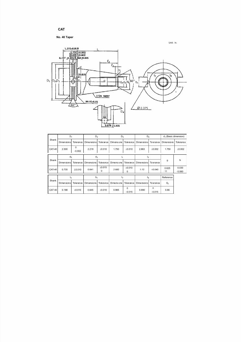
7/21/2019 MORISEIKI MAINTENANCE CLASS
http://slidepdf.com/reader/full/moriseiki-maintenance-class 197/409
CAT
No. 40 Taper
Unit: in.
Shank
D1 D2 D3 D4 d1 (Basic dimension)
Dimensions Tolerance Dimensions Tolerance Dimensions Tolerance Dimensions Tolerance Dimensions Tolerance
CAT-40 2.5000
−0.0022.219 ±0.010 1.750 ±0.010 2.863 ±0.002 1.750 ±0.002
Shank
d2 d3 L l2g N
Dimensions Tolerance Dimensions Tolerance Dimensions Tolerance Dimensions Tolerance
CAT-40 0.720 ±0.010 0.641±0.015
0 2.682±0.010
0 1.12 ±0.040 0.625−11
0.030
−0.060
Shank
l3 b1 t7 t8 Reference
Dimensions Tolerance Dimensions Tolerance Dimensions Tolerance Dimensions Tolerance d5
CAT-40 0.188 ±0.010 0.645 ±0.010 0.9850
−0.0150.890
0
−0.0150.86
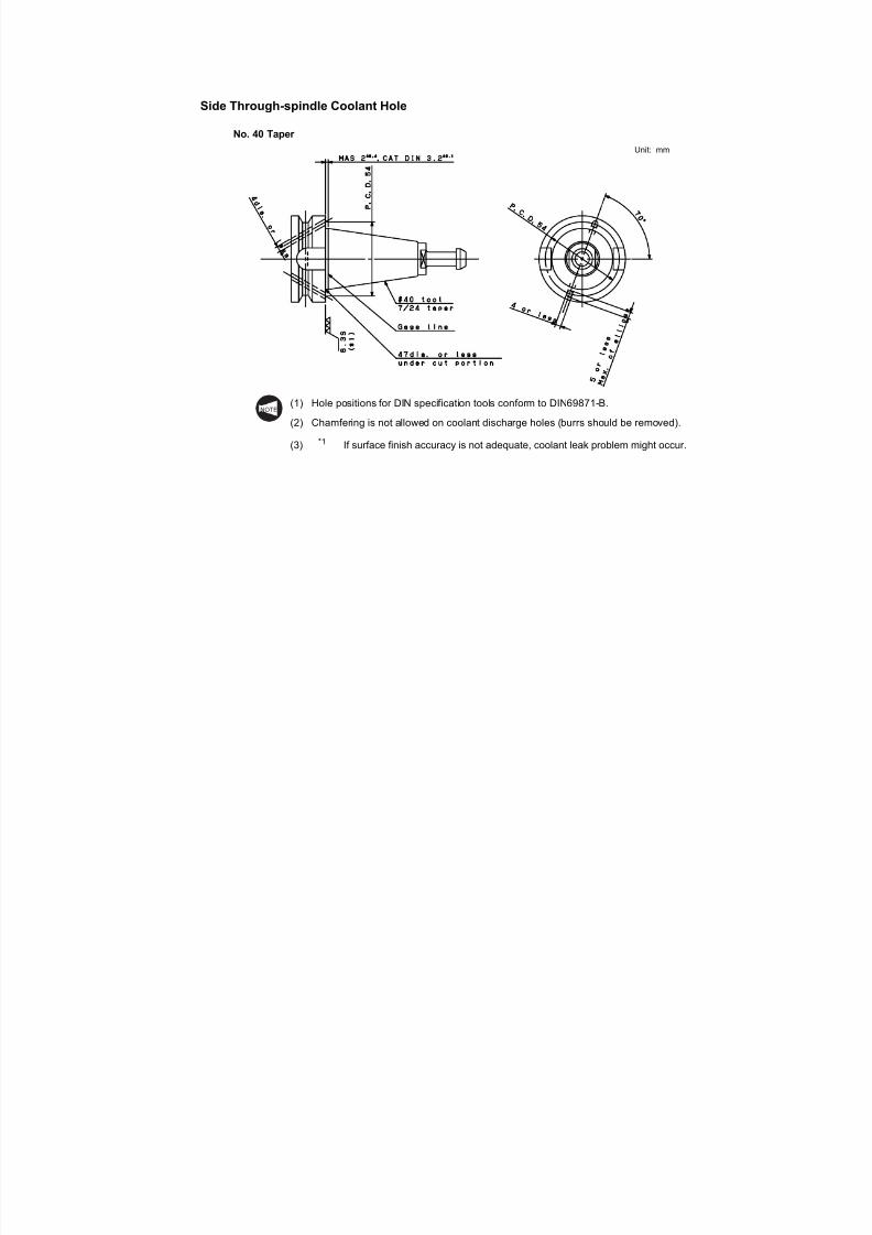
7/21/2019 MORISEIKI MAINTENANCE CLASS
http://slidepdf.com/reader/full/moriseiki-maintenance-class 198/409
Side Through-spindle Coolant Hole
No. 40 Taper
Unit: mm
(1) Hole positions for DIN specification tools conform to DIN69871-B.
(2) Chamfering is not allowed on coolant discharge holes (burrs should be removed).
(3) *1 If surface finish accuracy is not adequate, coolant leak problem might occur.
NOTE
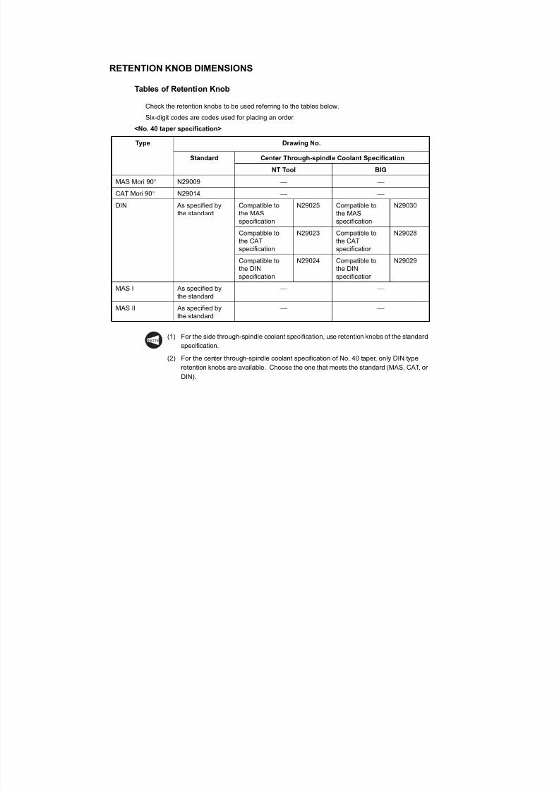
7/21/2019 MORISEIKI MAINTENANCE CLASS
http://slidepdf.com/reader/full/moriseiki-maintenance-class 199/409
RETENTION KNOB DIMENSIONS
Tables of Retention Knob
Check the retention knobs to be used referring to the tables below.
Six-digit codes are codes used for placing an order.
<No. 40 taper specification>
(1) For the side through-spindle coolant specification, use retention knobs of the standard
specification.
(2) For the center through-spindle coolant specification of No. 40 taper, only DIN type
retention knobs are available. Choose the one that meets the standard (MAS, CAT, or
DIN).
Type Drawing No.
Standard Center Through-spindle Coolant Specification
NT Tool BIG
MAS Mori 90° N29009
CAT Mori 90° N29014
DIN As specified bythe standard
Compatible tothe MASspecification
N29025 Compatible tothe MASspecification
N29030
Compatible tothe CATspecification
N29023 Compatible tothe CATspecification
N29028
Compatible tothe DINspecification
N29024 Compatible tothe DINspecification
N29029
MAS I As specified bythe standard
MAS II As specified bythe standard
NOTE
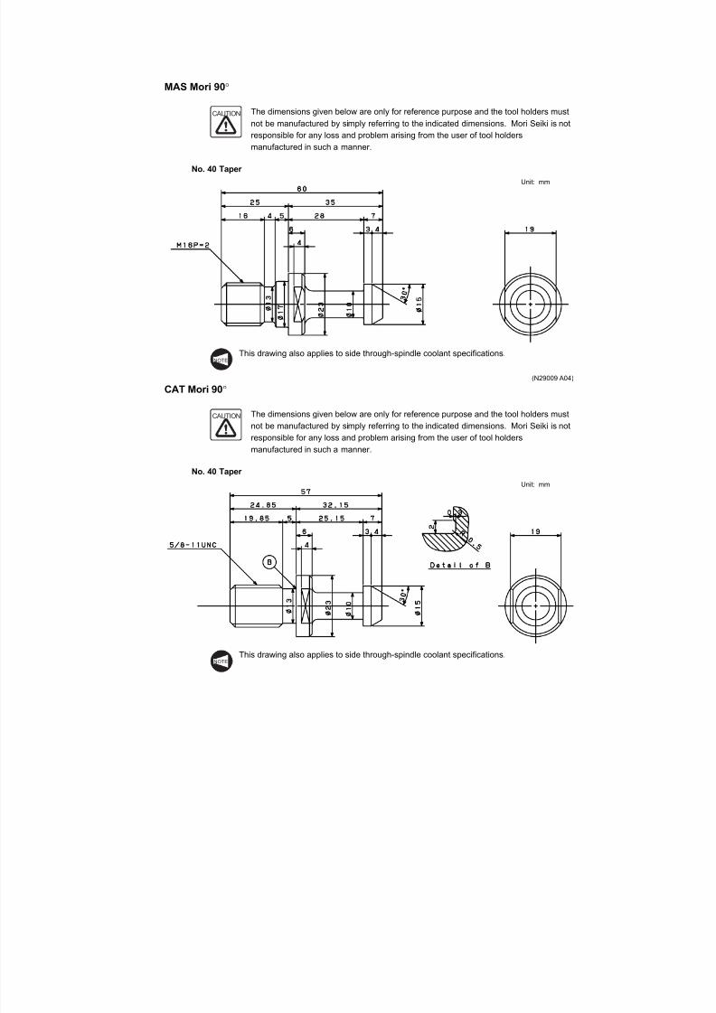
7/21/2019 MORISEIKI MAINTENANCE CLASS
http://slidepdf.com/reader/full/moriseiki-maintenance-class 200/409
MAS Mori 90°
The dimensions given below are only for reference purpose and the tool holders must
not be manufactured by simply referring to the indicated dimensions. Mori Seiki is notresponsible for any loss and problem arising from the user of tool holders
manufactured in such a manner.
No. 40 Taper
Unit: mm
This drawing also applies to side through-spindle coolant specifications.
(N29009 A04)
CAT Mori 90°
The dimensions given below are only for reference purpose and the tool holders must
not be manufactured by simply referring to the indicated dimensions. Mori Seiki is not
responsible for any loss and problem arising from the user of tool holders
manufactured in such a manner.
No. 40 Taper
Unit: mm
CAUTION
NOTE
CAUTION
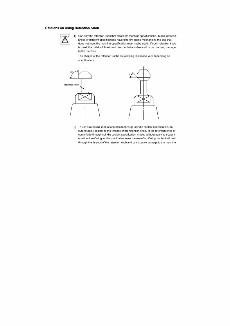
7/21/2019 MORISEIKI MAINTENANCE CLASS
http://slidepdf.com/reader/full/moriseiki-maintenance-class 201/409
Cautions on Using Retention Knob
(1) Use only the retention knob that meets the machine specifications. Since retention
knobs of different specifications have different clamp mechanism, the one thatdoes not meet the machine specification must not be used. If such retention knob
is used, the collet will break and unexpected accidents will occur, causing damage
to the machine.
The shapes of the retention knobs as following illustration vary depending on
specifications.
(2) To use a retention knob of center/side through-spindle coolant specification, be
sure to apply sealant to the threads of the retention knob. If the retention knob of
center/side through-spindle coolant specification is used without applying sealant
or without an O-ring for the one that requires the use of an O-ring, coolant will leak
through the threads of the retention knob and could cause damage to the machine.
CAUTION
90°
Retention knob
θ
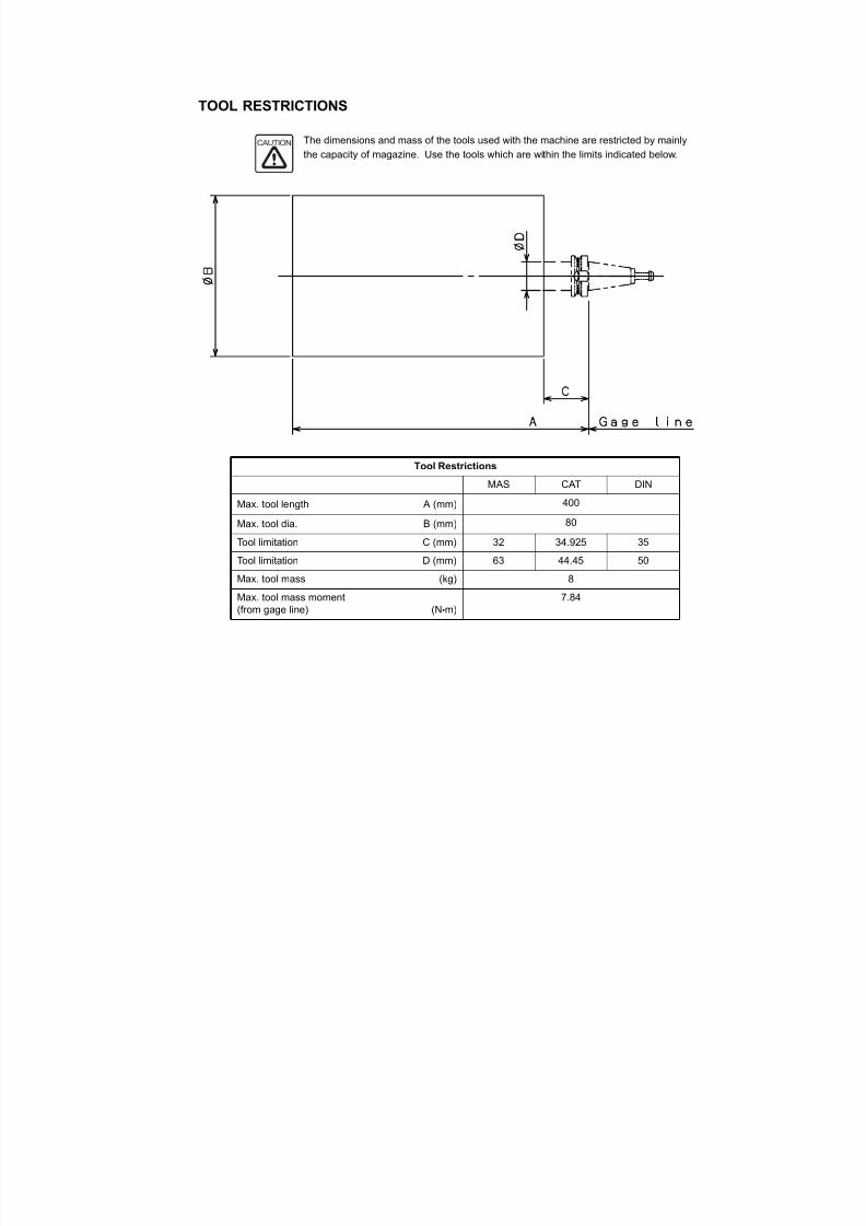
7/21/2019 MORISEIKI MAINTENANCE CLASS
http://slidepdf.com/reader/full/moriseiki-maintenance-class 202/409
TOOL RESTRICTIONS
The dimensions and mass of the tools used with the machine are restricted by mainly
the capacity of magazine. Use the tools which are within the limits indicated below.
Tool Restrictions
MAS CAT DIN
Max. tool length A (mm) 400
Max. tool dia. B (mm) 80
Tool limitation C (mm) 32 34.925 35
Tool limitation D (mm) 63 44.45 50
Max. tool mass (kg) 8
Max. tool mass moment
(from gage line) (N•m)
7.84
CAUTION
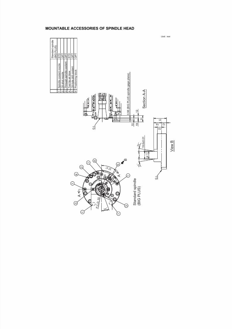
7/21/2019 MORISEIKI MAINTENANCE CLASS
http://slidepdf.com/reader/full/moriseiki-maintenance-class 203/409
MOUNTABLE ACCESSORIES OF SPINDLE HEAD
Unit: mm
1 2
1 9
0 . 9
8 ( B I G
P L U S
s p
i n d l e g a g e
p l a n e
)
S e c
t i o n
A - A
1 0
3 1
1
1
1
2
3 3
4
5
3 7 . 5
R 6 5
P . C .
D .
5 5
2 0
1 0
1 2 1 9
3 1
1 8
+ 0
. 0 3
- 0 . 0
1
1 9
. 6 ± 0
. 0 1
1 0
1 0
B
G . L
A
A
6
G . L
V i e w
B
S t a n
d a r d s p
i n d l e
( B
I G
P L U S )
1 2 3 6 5
S T D
O P T
O P T
S T D
O P T
4
S p i n d l e c o o l a n t n o z z l e
S t a n d a r d s p i n d l e
( B I G
P L U S )
O i l s h o
t n o z z l e
T h r o u g
h - s p i n d l e c o o l a n t
P o s i t i o
n i n g b l o c k
O i l - h o l e d r i l l c o o l a n t
T o o l t i p
a i r b l o w
O P T
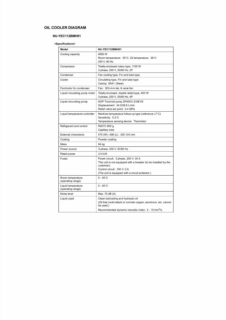
7/21/2019 MORISEIKI MAINTENANCE CLASS
http://slidepdf.com/reader/full/moriseiki-maintenance-class 204/409
OIL COOLER DIAGRAM
NU-YEC112BMH01
<Specifications>
Model NU-YEC112BMH01
Cooling capacity 4650 W
Room temperature: 35°C, Oil temperature: 38°C
200 V, 60 Hz
Compressor Totally-enclosed rotary type, 1100 W
3-phase, 200 V, 50/60 Hz, 2P
Condenser Fan cooling type, Fin and tube type
Cooler Circulating type, Fin and tube typeCasing: SS41 (Steel)
Fan/motor for condenser Fan: 300-mm dia. 6-vane fan
Liquid circulating pump motor Totally enclosed, double sided type, 400 W
3-phase, 200 V, 50/60 Hz, 4P
Liquid circulating pump NOP Trochoid pump 2P400C-216EVS
Displacement: 24.0/28.8 L/min
Relief valve set point: 0.4 MPa
Liquid temperature controller Machine temperature follow-up type (reference ±7°C)
Sensitivity: 0.2°CTemperature sensing device: Thermistor
Refrigerant and control R407C 800 g
Capillary tube
External dimensions 475 (W) × 590 (L) × 821 (H) mm
Coating Powder coating
Mass 94 kg
Power source 3-phase, 200 V, 50/60 Hz
Rated power 3.4 kVA
Fuses Power circuit: 3-phase, 200 V, 30 AThis unit is not equipped with a breaker (to be installed by thecustomer).
Control circuit: 100 V, 2 A
(The unit is equipped with a circuit protector.)
Room temperature(operating range)
5 - 40°C
Liquid temperature(operating range)
5 - 40°C
Noise level Max. 70 dB (A)
Liquid used Clean lubricating and hydraulic oil(Oil that could attack or corrode copper, aluminum, etc. cannotbe used )

7/21/2019 MORISEIKI MAINTENANCE CLASS
http://slidepdf.com/reader/full/moriseiki-maintenance-class 205/409
Connection port size Inlet: Rc 3/4
Outlet: Rc 3/4
Protective devices Pressure switch (shutting off high pressure)
Spark quencher
Overload protector (compressor, pump motor)
Terminal block For alarm output (24NC, 0CAL “a” contact)
Remarks This unit is not waterproof and must be kept away from water.Splashing water may cause serious damage to the unit.
Model NU-YEC112BMH01
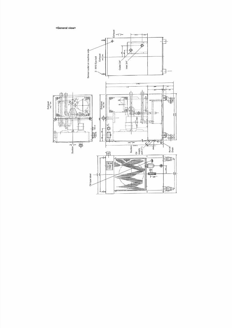
7/21/2019 MORISEIKI MAINTENANCE CLASS
http://slidepdf.com/reader/full/moriseiki-maintenance-class 206/409
<General view>
S u c t i o n
E x h a u s t
S u c t i o n
E x h a u s t
E x h a u s t
2 - M 1 0 E y e b o l t
I n l e t 3 / 4 ”
O u t l e t 3 / 4 ”
O i l
s u p p l y
p o r t ( 1 ” )
O i l t y p e l a b e l
R c 1 / 4 ”
D r a i n
E x h a u s t
S e n s o r o u t l e t o n m a c h i n e s i d e
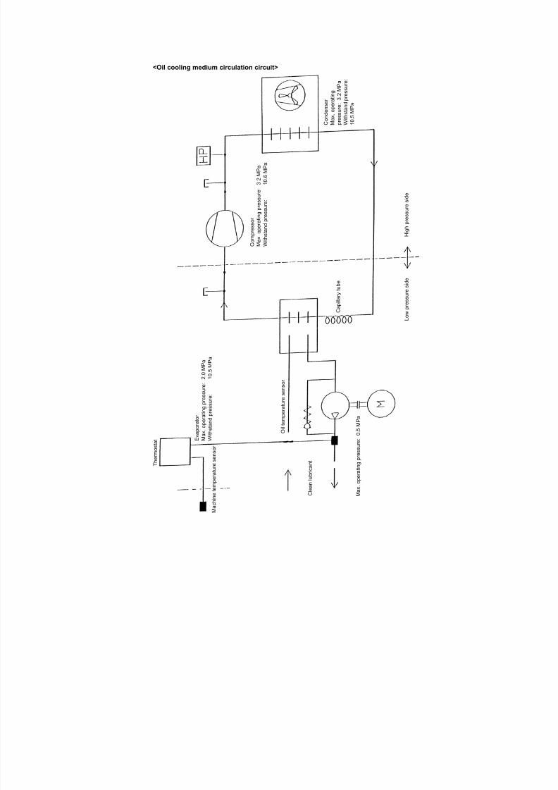
7/21/2019 MORISEIKI MAINTENANCE CLASS
http://slidepdf.com/reader/full/moriseiki-maintenance-class 207/409
<Oil cooling medium circulation circuit>
C o n d e n s e r
M a x . o p e r a t i n g
p r e s s u r e : 3 .
2 M P a
W i t h s t a n d p r e s s u r e :
1 0 . 5 M P a
C o m p r e s s o r
M a x . o p e r a t i n g p r e s s u r e : 3 . 2 M P a
W i t h s t a n d p r e s s u r e :
1 0 . 6 M P a
H i g h p r e s s u r e s i d e
L o w p r e s s u r e s i d e
C a p i l l a r y
t u b e
E v a p o r a t o r
M a x . o p e r a t i n g p r e s s u
r e : 2 . 0 M P a
W i t h s t a n d p r e s s u r e :
1 0 . 5 M P a
O i l t e m p e r a t u r e s e n s o r
C l e a n l u b r i c a n t
M a x
. o p e r a t i n g p r e s s u r e : 0 . 5 M P a
a c h i n e t e m p e r a t u r e s e n s o r
T h e r m o s t a t

7/21/2019 MORISEIKI MAINTENANCE CLASS
http://slidepdf.com/reader/full/moriseiki-maintenance-class 208/409
<Electrical parts list>
Code Unit Name Type Q’ty Manufacturer
M81
F3R
Compressor
Compressor internalthermostat
4KS250MAA, 1100 W3φ, 2P, 200 V, 50/60 Hz 1 MatsushitaElectric
M83 Trochoid pump motor FELQ-8T, 400 W
3φ, 4P, 200/200, 220 V, 50/60 Hz
1 YaskawaElectric
S2F High-pressure pressureswitch
FTB-Z231 (Manual return: 3.2 MPa)
VDE approved
1 SaginomiyaSeisakusho
K81M Magnetic switch forcompressor
SC-03, 100 VAC
TÜV approved
1 Fuji Electric
K83M Magnetic switch forTrochoid pump
SC-03, 100 VACTÜV approved
1 Fuji Electric
F81R Overcurrent relay forcompressor
TR-0N/3, 7.5 A set
TÜV approved
1 Fuji Electric
F83R Overcurrent relay forTrochoid pump
TR-0N/3, 2.2 A set 1 Fuji Electric
K1H Alarm relay HH62S-100V
VDE approved
1 Fuji Electric
N1 Thermostat T6DIK-A610A, 200 V
46-W24070
Negative phase prevention relay,40 sec. with built-in OFF timer
1 Taiko Sangyo
R3 Thermistor (Machine temperature)
06-W26381 1
R2 Thermistor (Oil temperature)
06-W24731 1
R1 Temperature adjustingvariable resistor
W-247 B2KΩ 1
Q1F Circuit protector CP31E/2, 2 A
250 VAC, 50/60 Hz
TÜV approved
1 Fuji Electric
Z1
Z2
Z3
Spark quencher 3CRE-50500
3CRE-50500
CRE-30680
VDE approved
1
1
1
Okaya Electric
H1 Operation indicating lamp(white)
MB105 WFU 1 Metro Electric
H2 Alarm indicating lamp(orange)
MB105 OFU 1 Metro Electric
X1 Terminal block AYBN016-1 AYBN011-1
IEC conformed
11 Fuji Electric

7/21/2019 MORISEIKI MAINTENANCE CLASS
http://slidepdf.com/reader/full/moriseiki-maintenance-class 209/409
XP306 Connector Han 6E
Housing 09300060302
Insert 09330062602
Contact 09330006103 3 pcs.
09330006105 2 pcs.
1 HartingElectronic
XP307 Han 7D
Housing 09200030320
Insert 09210073031
Contact 09150006102 2 pcs.
09150006104 2 pcs.
09150006101 1 pc.
1
Code Unit Name Type Q’ty Manufacturer
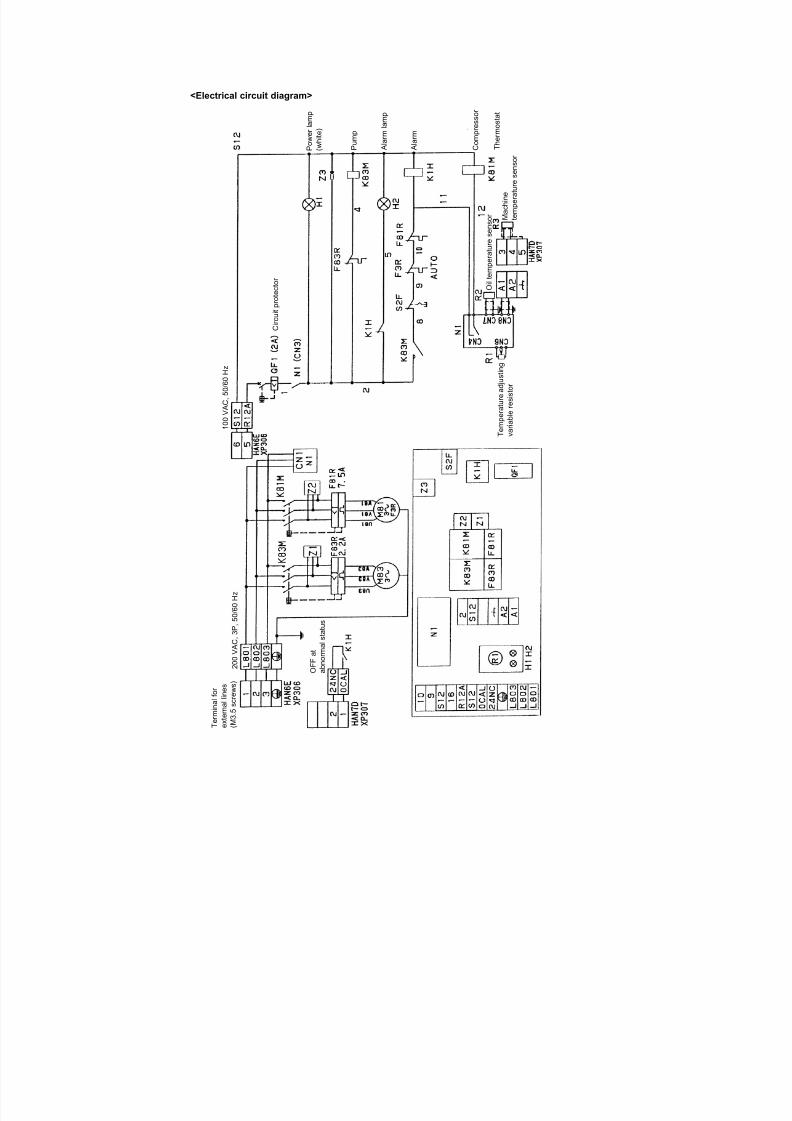
7/21/2019 MORISEIKI MAINTENANCE CLASS
http://slidepdf.com/reader/full/moriseiki-maintenance-class 210/409
<Electrical circuit diagram>
P o w
e r l a m p
( w h i t e )
P u m
p
A l a r m l a m p
A l a r m
C o m
p r e s s o r
T h e r m o s t a t
M a c h i n e
t e m p e r a t u r e s e n s o r
O i l t e
m p e r a t u r e s e n s o r
C i r c u i t p r o t e c t o r
T e m p e
r a t u r e a d j u s t i n g
v a r i a b l e r e s i s t o r
O F F a t
a b n o r m a l s t a t u s
2 0 0 V A C , 3 P , 5 0 / 6 0 H z
1 0 0 V A C , 5 0 / 6 0 H z
r m i n a l f o
r
t e r n a l l i n e s
3 . 5 s c r e w s )
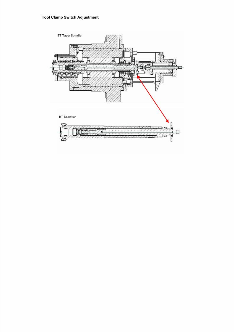
7/21/2019 MORISEIKI MAINTENANCE CLASS
http://slidepdf.com/reader/full/moriseiki-maintenance-class 211/409
BT Taper Spindle
BT Drawbar
Tool Clamp Switch Adjustment
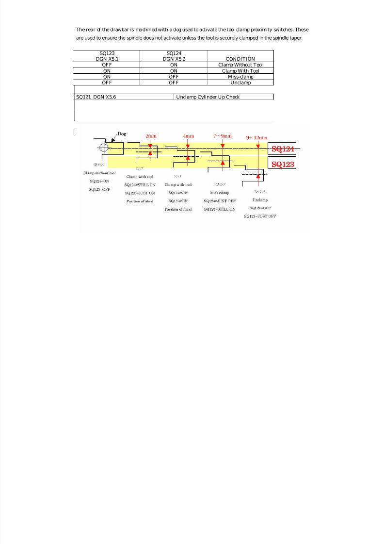
7/21/2019 MORISEIKI MAINTENANCE CLASS
http://slidepdf.com/reader/full/moriseiki-maintenance-class 212/409
The rear of the drawbar is machined with a dog used to activate the tool clamp proximity switches. These
are used to ensure the spindle does not activate unless the tool is securely clamped in the spindle taper.
SQ123DGN X5.1
SQ124DGN X5.2 CONDITION
OFF ON Clamp Without ToolON ON Clamp With ToolON OFF Miss-clampOFF OFF Unclamp
SQ121 DGN X5.6 Unclamp Cylinder Up Check
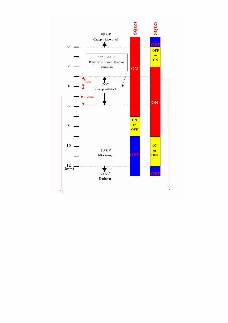
7/21/2019 MORISEIKI MAINTENANCE CLASS
http://slidepdf.com/reader/full/moriseiki-maintenance-class 213/409
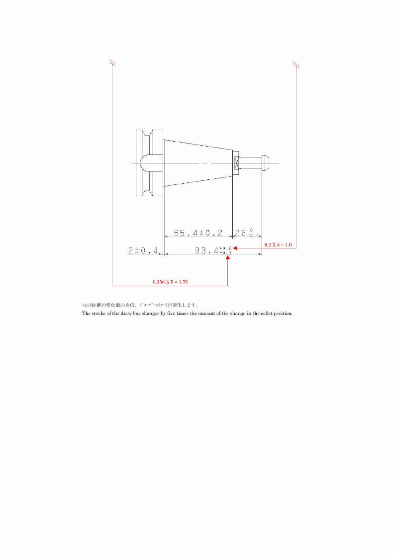
7/21/2019 MORISEIKI MAINTENANCE CLASS
http://slidepdf.com/reader/full/moriseiki-maintenance-class 214/409
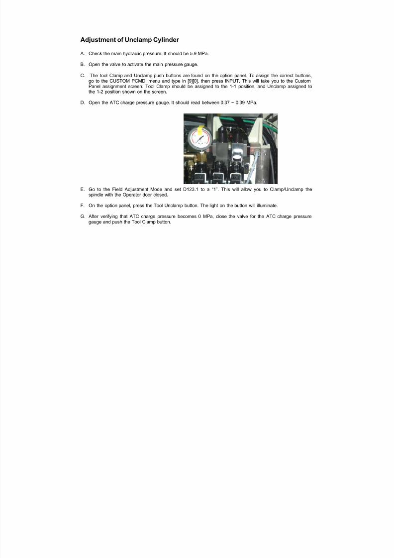
7/21/2019 MORISEIKI MAINTENANCE CLASS
http://slidepdf.com/reader/full/moriseiki-maintenance-class 215/409
Adjustment of Unclamp Cylinder
A. Check the main hydraulic pressure. It should be 5.9 MPa.
B. Open the valve to activate the main pressure gauge.
C. The tool Clamp and Unclamp push buttons are found on the option panel. To assign the correct buttons,go to the CUSTOM PCMDI menu and type in [9][0], then press INPUT. This will take you to the CustomPanel assignment screen. Tool Clamp should be assigned to the 1-1 position, and Unclamp assigned tothe 1-2 position shown on the screen.
D. Open the ATC charge pressure gauge. It should read between 0.37 ~ 0.39 MPa.
E. Go to the Field Adjustment Mode and set D123.1 to a “1”. This will allow you to Clamp/Unclamp thespindle with the Operator door closed.
F. On the option panel, press the Tool Unclamp button. The light on the button will illuminate.
G. After verifying that ATC charge pressure becomes 0 MPa, close the valve for the ATC charge pressuregauge and push the Tool Clamp button.
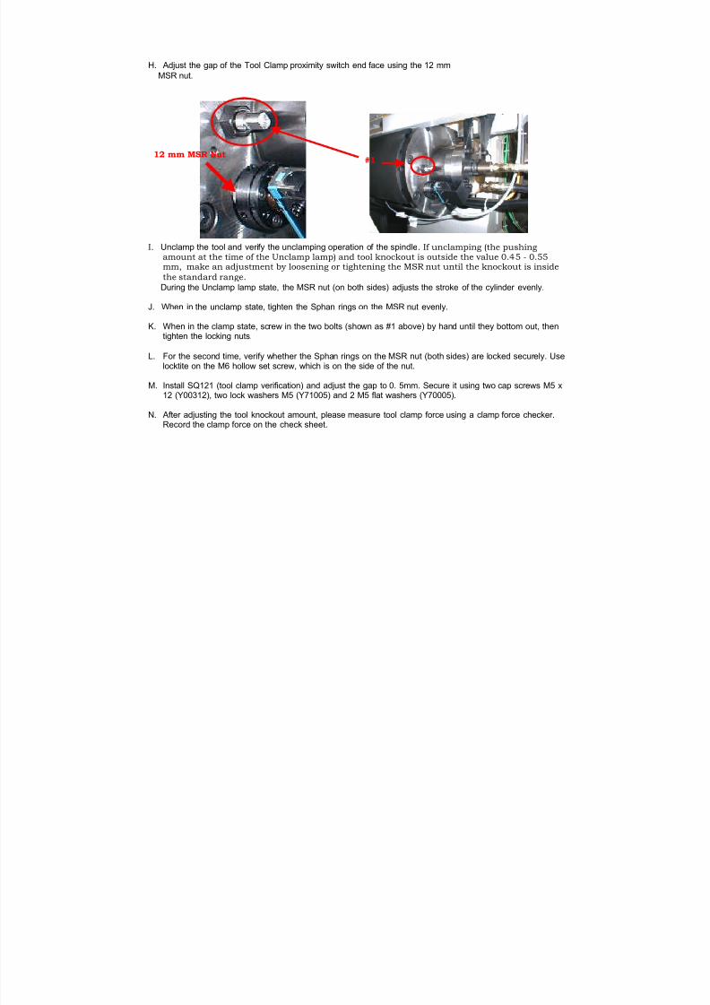
7/21/2019 MORISEIKI MAINTENANCE CLASS
http://slidepdf.com/reader/full/moriseiki-maintenance-class 216/409
H. Adjust the gap of the Tool Clamp proximity switch end face using the 12 mm MSR nut.
I. Unclamp the tool and verify the unclamping operation of the spindle . If unclamping (the pushingamount at the time of the Unclamp lamp) and tool knockout is outside the value 0.45 - 0.55mm, make an adjustment by loosening or tightening the MSR nut until the knockout is inside
the standard range.
During the Unclamp lamp state, the MSR nut (on both sides) adjusts the stroke of the cylinder evenly.
J. When in the unclamp state, tighten the Sphan rings on the MSR nut evenly.
K. When in the clamp state, screw in the two bolts (shown as #1 above) by hand until they bottom out, thentighten the locking nuts.
L. For the second time, verify whether the Sphan rings on the MSR nut (both sides) are locked securely. Uselocktite on the M6 hollow set screw, which is on the side of the nut.
M. Install SQ121 (tool clamp verification) and adjust the gap to 0. 5mm. Secure it using two cap screws M5 x12 (Y00312), two lock washers M5 (Y71005) and 2 M5 flat washers (Y70005).
N. After adjusting the tool knockout amount, please measure tool clamp force using a clamp force checker.Record the clamp force on the check sheet.
12 mm MSR Nut#1
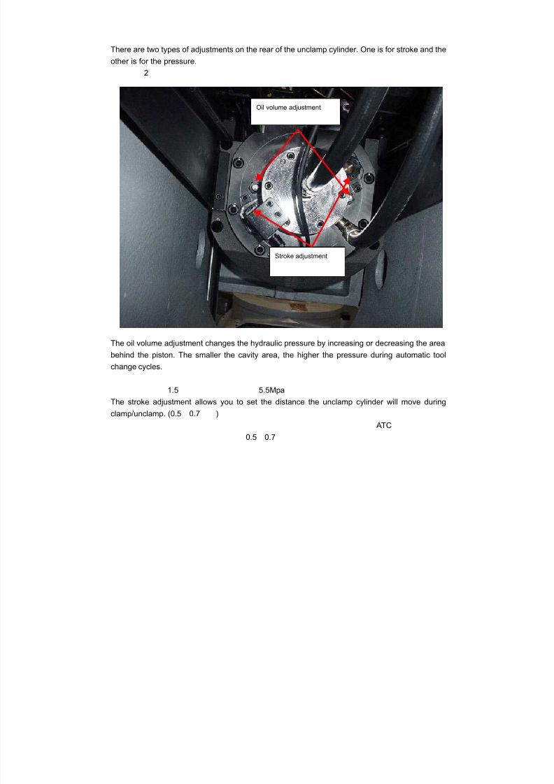
7/21/2019 MORISEIKI MAINTENANCE CLASS
http://slidepdf.com/reader/full/moriseiki-maintenance-class 217/409
There are two types of adjustments on the rear of the unclamp cylinder. One is for stroke and the
other is for the pressure.
2
The oil volume adjustment changes the hydraulic pressure by increasing or decreasing the area
behind the piston. The smaller the cavity area, the higher the pressure during automatic tool
change cycles.
1.5 5.5MpaThe stroke adjustment allows you to set the distance the unclamp cylinder will move during
clamp/unclamp. (0.5 0.7 )
ATC
0.5 0.7
Oil volume adjustment
Stroke adjustment
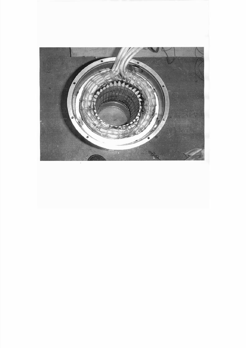
7/21/2019 MORISEIKI MAINTENANCE CLASS
http://slidepdf.com/reader/full/moriseiki-maintenance-class 218/409
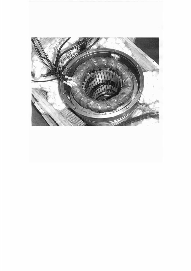
7/21/2019 MORISEIKI MAINTENANCE CLASS
http://slidepdf.com/reader/full/moriseiki-maintenance-class 219/409
7/21/2019 MORISEIKI MAINTENANCE CLASS
http://slidepdf.com/reader/full/moriseiki-maintenance-class 220/409
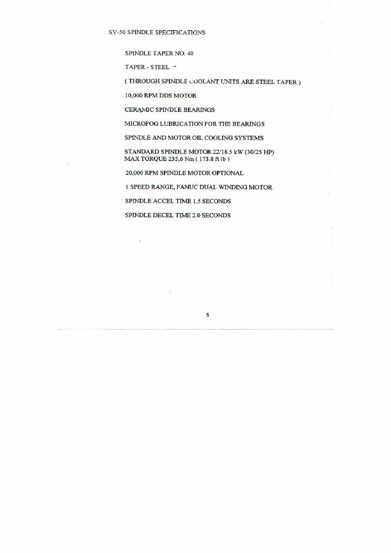
7/21/2019 MORISEIKI MAINTENANCE CLASS
http://slidepdf.com/reader/full/moriseiki-maintenance-class 221/409

7/21/2019 MORISEIKI MAINTENANCE CLASS
http://slidepdf.com/reader/full/moriseiki-maintenance-class 222/409
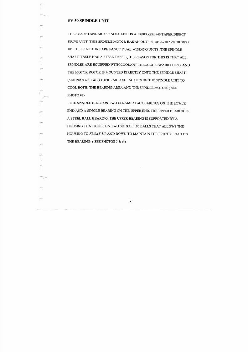
7/21/2019 MORISEIKI MAINTENANCE CLASS
http://slidepdf.com/reader/full/moriseiki-maintenance-class 223/409
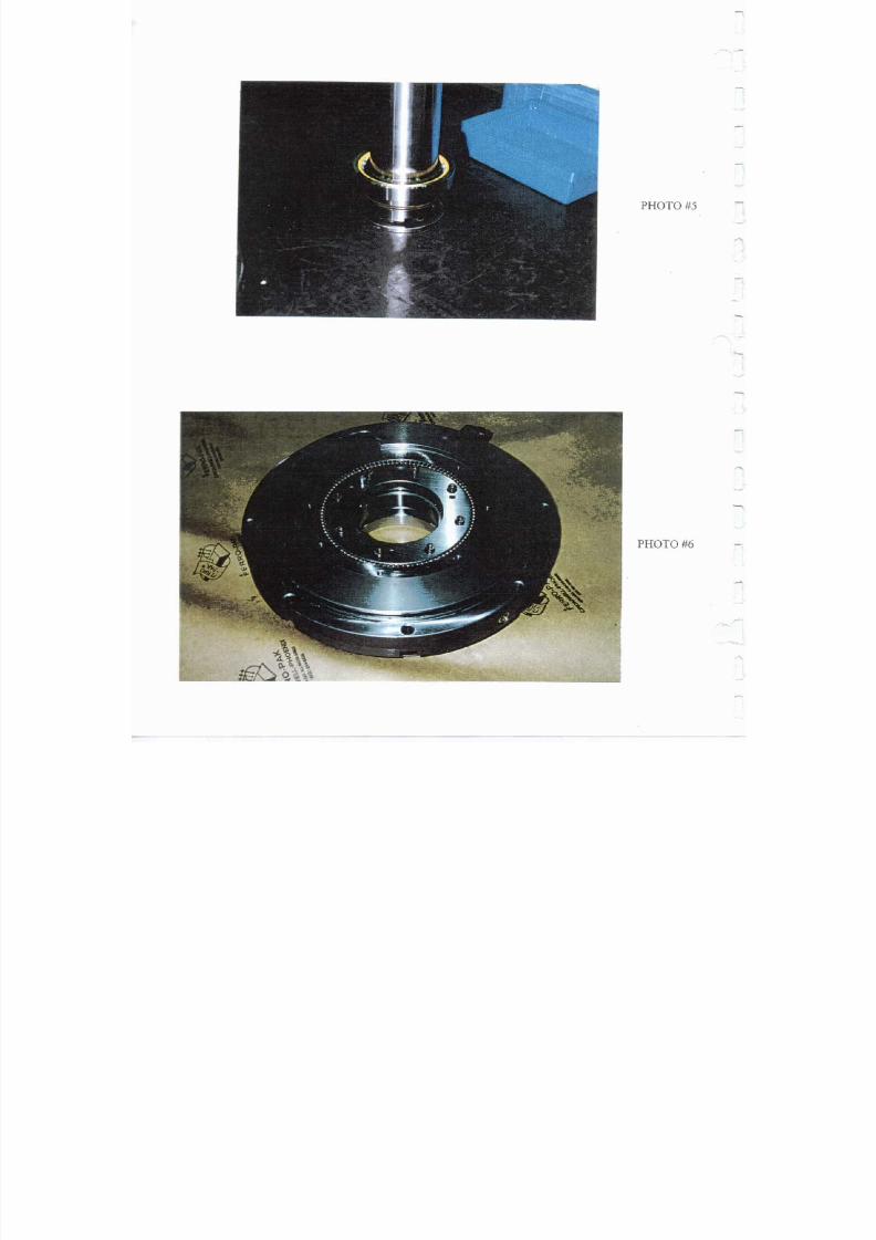
7/21/2019 MORISEIKI MAINTENANCE CLASS
http://slidepdf.com/reader/full/moriseiki-maintenance-class 224/409
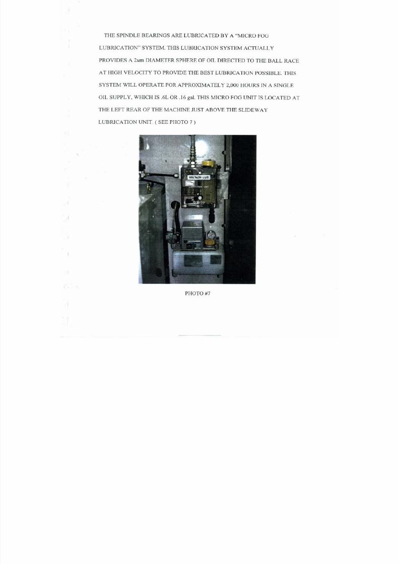
7/21/2019 MORISEIKI MAINTENANCE CLASS
http://slidepdf.com/reader/full/moriseiki-maintenance-class 225/409
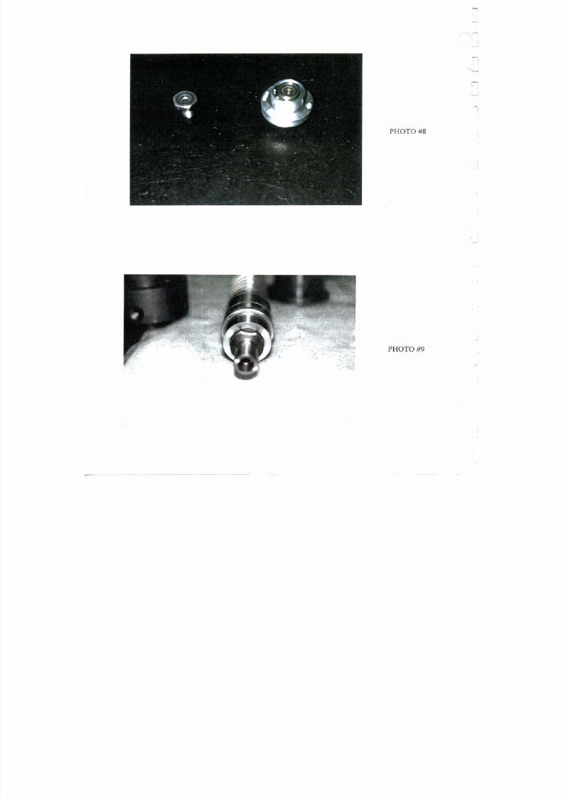
7/21/2019 MORISEIKI MAINTENANCE CLASS
http://slidepdf.com/reader/full/moriseiki-maintenance-class 226/409
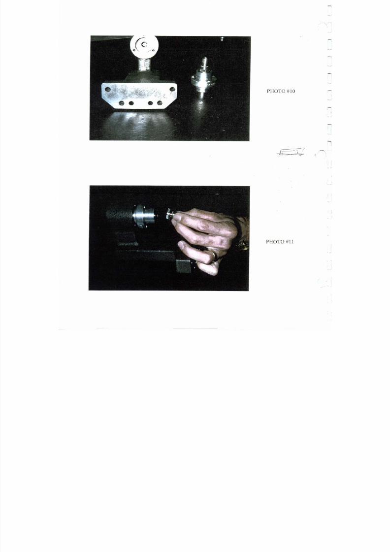
7/21/2019 MORISEIKI MAINTENANCE CLASS
http://slidepdf.com/reader/full/moriseiki-maintenance-class 227/409
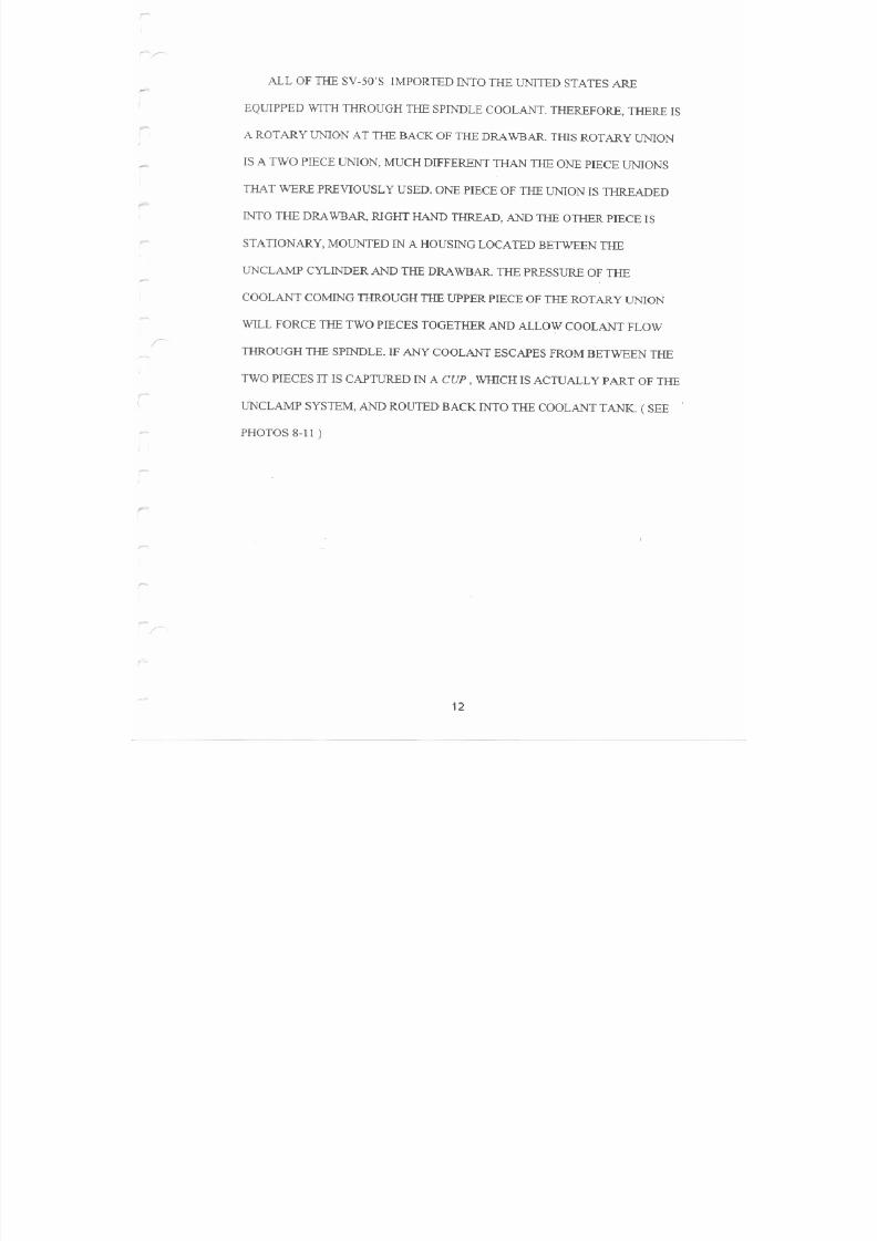
7/21/2019 MORISEIKI MAINTENANCE CLASS
http://slidepdf.com/reader/full/moriseiki-maintenance-class 228/409
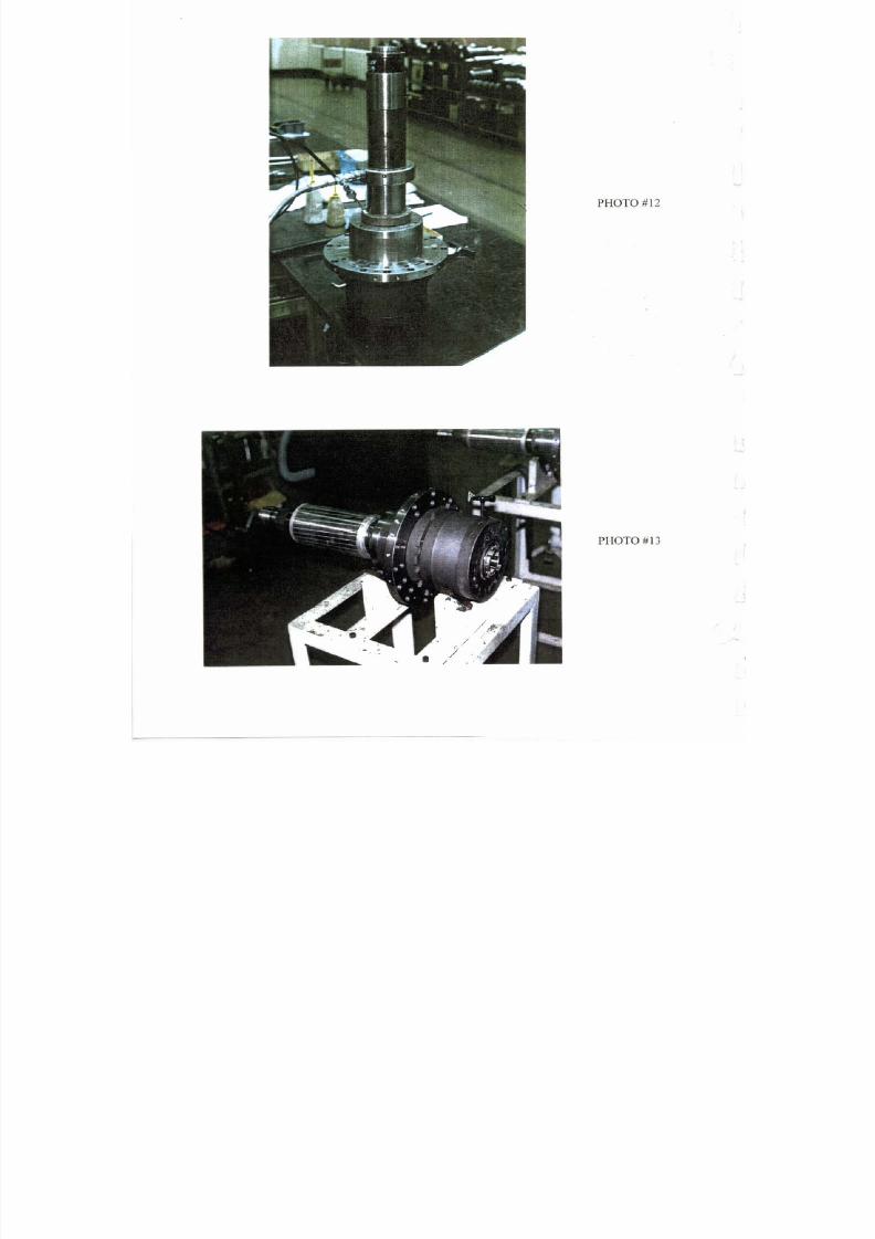
7/21/2019 MORISEIKI MAINTENANCE CLASS
http://slidepdf.com/reader/full/moriseiki-maintenance-class 229/409
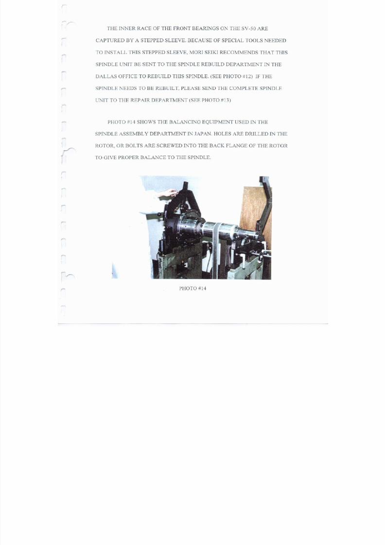
7/21/2019 MORISEIKI MAINTENANCE CLASS
http://slidepdf.com/reader/full/moriseiki-maintenance-class 230/409
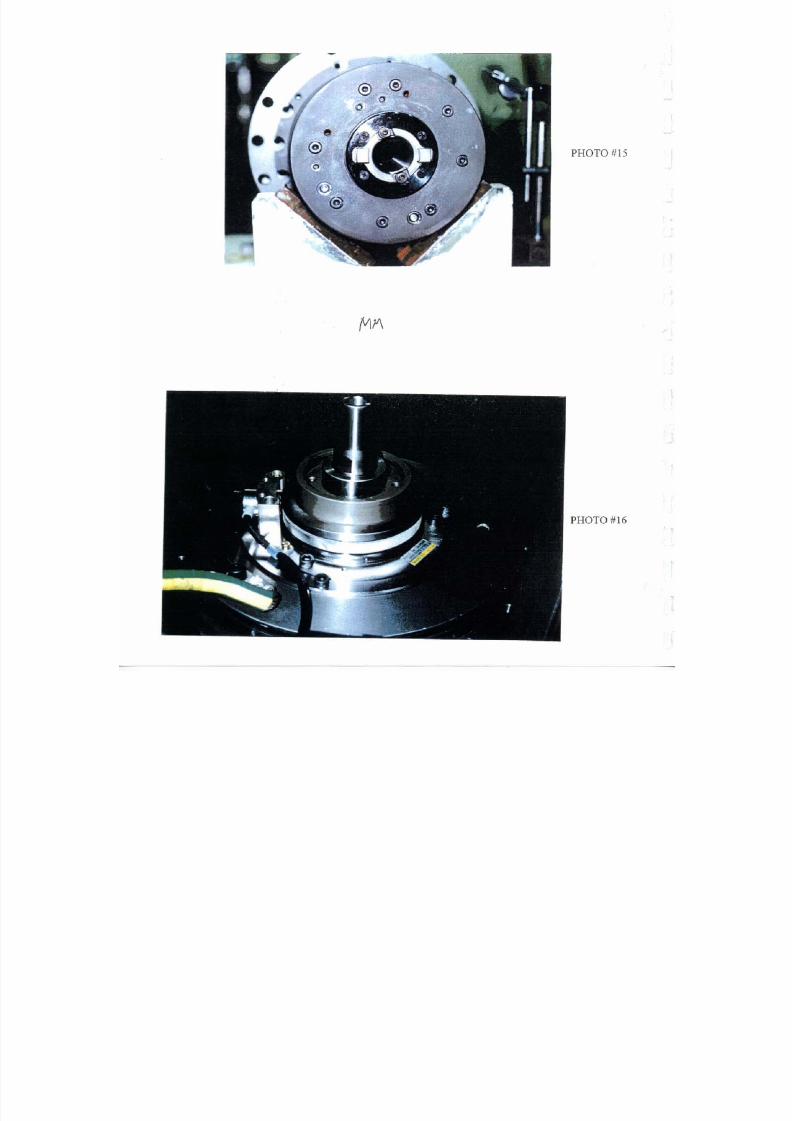
7/21/2019 MORISEIKI MAINTENANCE CLASS
http://slidepdf.com/reader/full/moriseiki-maintenance-class 231/409
7/21/2019 MORISEIKI MAINTENANCE CLASS
http://slidepdf.com/reader/full/moriseiki-maintenance-class 232/409

7/21/2019 MORISEIKI MAINTENANCE CLASS
http://slidepdf.com/reader/full/moriseiki-maintenance-class 233/409
7/21/2019 MORISEIKI MAINTENANCE CLASS
http://slidepdf.com/reader/full/moriseiki-maintenance-class 234/409
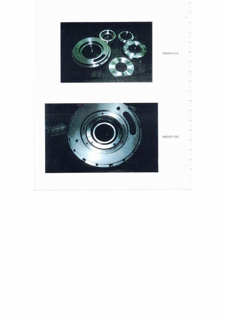
7/21/2019 MORISEIKI MAINTENANCE CLASS
http://slidepdf.com/reader/full/moriseiki-maintenance-class 235/409
7/21/2019 MORISEIKI MAINTENANCE CLASS
http://slidepdf.com/reader/full/moriseiki-maintenance-class 236/409
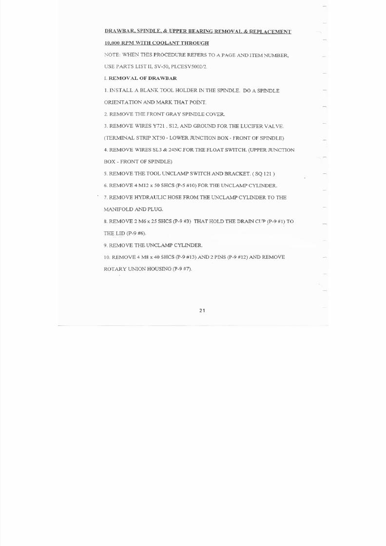
7/21/2019 MORISEIKI MAINTENANCE CLASS
http://slidepdf.com/reader/full/moriseiki-maintenance-class 237/409
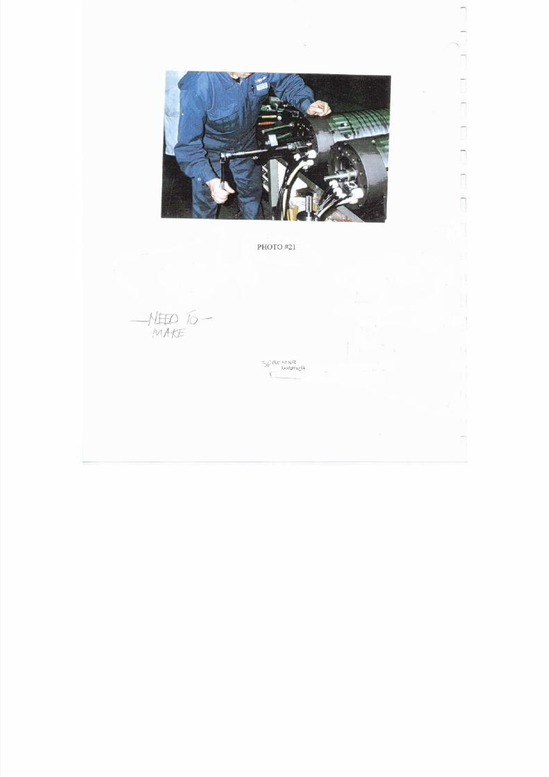
7/21/2019 MORISEIKI MAINTENANCE CLASS
http://slidepdf.com/reader/full/moriseiki-maintenance-class 238/409
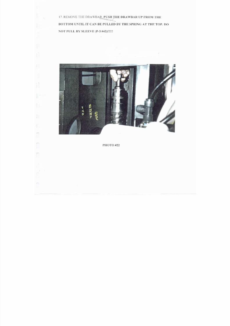
7/21/2019 MORISEIKI MAINTENANCE CLASS
http://slidepdf.com/reader/full/moriseiki-maintenance-class 239/409
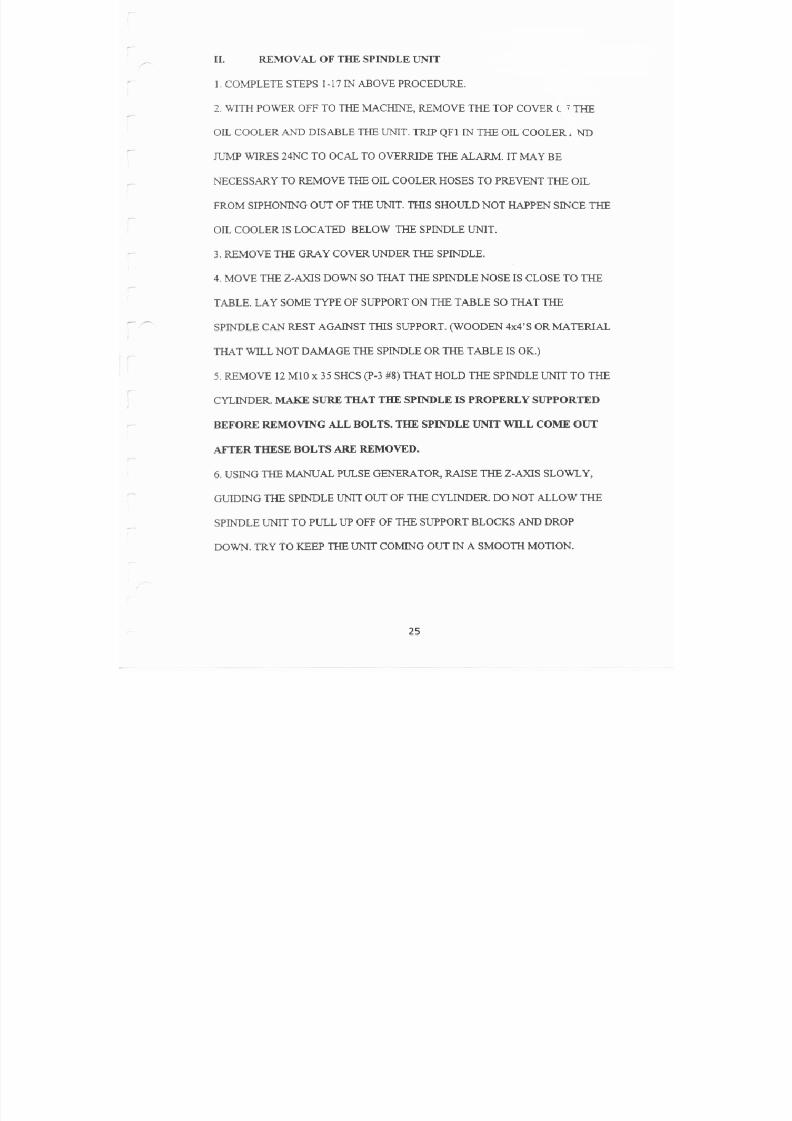
7/21/2019 MORISEIKI MAINTENANCE CLASS
http://slidepdf.com/reader/full/moriseiki-maintenance-class 240/409
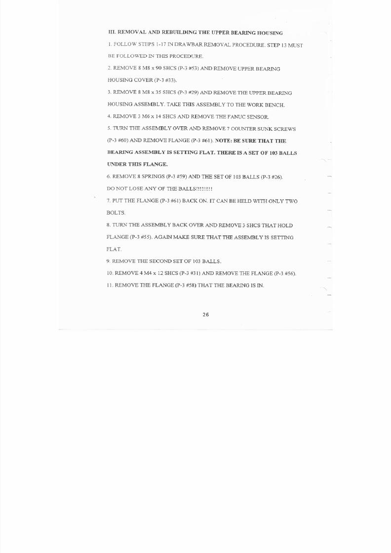
7/21/2019 MORISEIKI MAINTENANCE CLASS
http://slidepdf.com/reader/full/moriseiki-maintenance-class 241/409
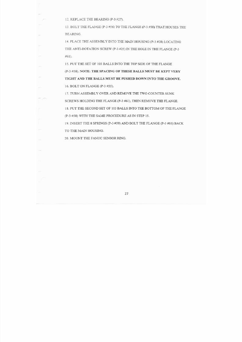
7/21/2019 MORISEIKI MAINTENANCE CLASS
http://slidepdf.com/reader/full/moriseiki-maintenance-class 242/409
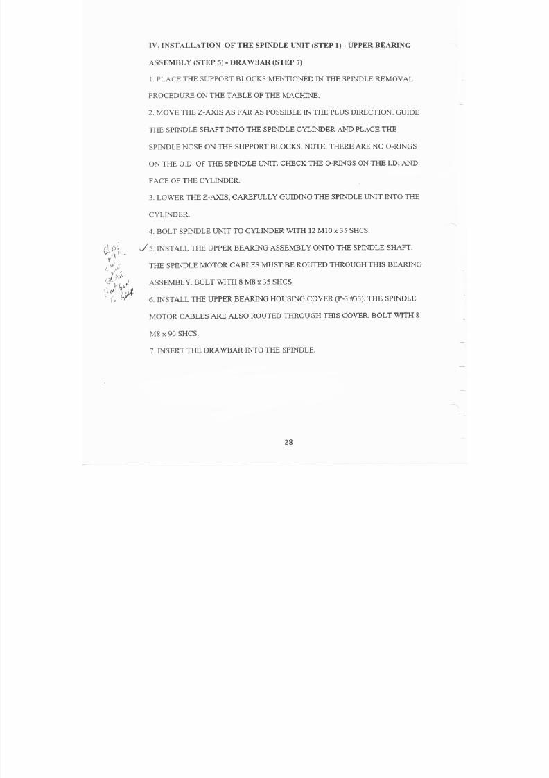
7/21/2019 MORISEIKI MAINTENANCE CLASS
http://slidepdf.com/reader/full/moriseiki-maintenance-class 243/409
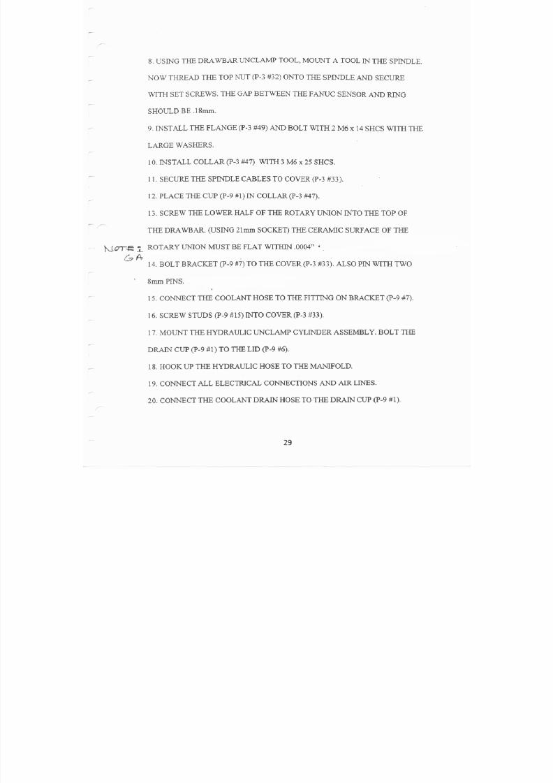
7/21/2019 MORISEIKI MAINTENANCE CLASS
http://slidepdf.com/reader/full/moriseiki-maintenance-class 244/409

7/21/2019 MORISEIKI MAINTENANCE CLASS
http://slidepdf.com/reader/full/moriseiki-maintenance-class 245/409

7/21/2019 MORISEIKI MAINTENANCE CLASS
http://slidepdf.com/reader/full/moriseiki-maintenance-class 246/409
SPINDLE AND DRAWBAR
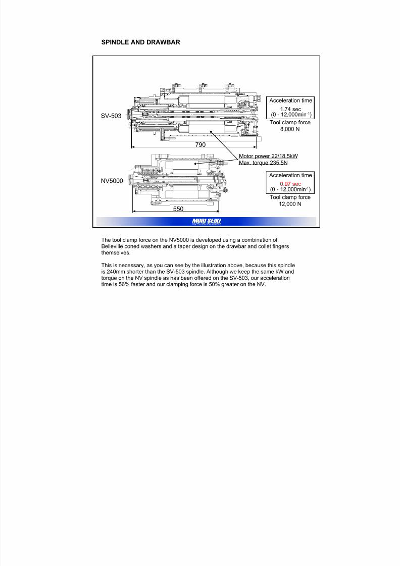
7/21/2019 MORISEIKI MAINTENANCE CLASS
http://slidepdf.com/reader/full/moriseiki-maintenance-class 247/409
SPINDLE AND DRAWBAR
The tool clamp force on the NV5000 is developed using a combination of Belleville coned washers and a taper design on the drawbar and collet fingersthemselves.
This is necessary, as you can see by the illustration above, because this spindleis 240mm shorter than the SV-503 spindle. Although we keep the same kW and
torque on the NV spindle as has been offered on the SV-503, our accelerationtime is 56% faster and our clamping force is 50% greater on the NV.
Acceleration time
1.74 sec (0 - 12,000min-1)
Acceleration time
0.97 sec(0 - 12,000min-1)
Motor power 22/18.5kW
Max. torque 235.5N
SV-503
NV5000
790
550
Tool clamp force
8,000 N
Tool clamp force
12,000 N
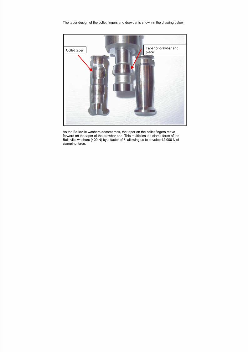
7/21/2019 MORISEIKI MAINTENANCE CLASS
http://slidepdf.com/reader/full/moriseiki-maintenance-class 248/409
The taper design of the collet fingers and drawbar is shown in the drawing below.
As the Belleville washers decompress, the taper on the collet fingers moveforward on the taper of the drawbar end. This multiplies the clamp force of theBelleville washers (400 N) by a factor of 3, allowing us to develop 12,000 N of clamping force.
Taper of drawbar endpiece
Collet taper
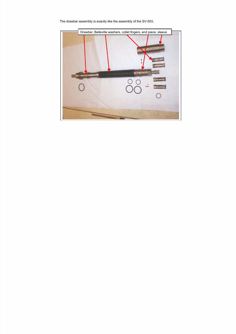
7/21/2019 MORISEIKI MAINTENANCE CLASS
http://slidepdf.com/reader/full/moriseiki-maintenance-class 249/409
The drawbar assembly is exactly like the assembly of the SV-503.
Drawbar, Belleville washers, collet fingers, end piece, sleeve
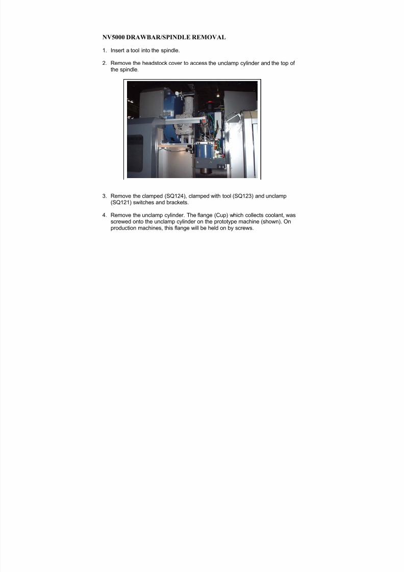
7/21/2019 MORISEIKI MAINTENANCE CLASS
http://slidepdf.com/reader/full/moriseiki-maintenance-class 250/409
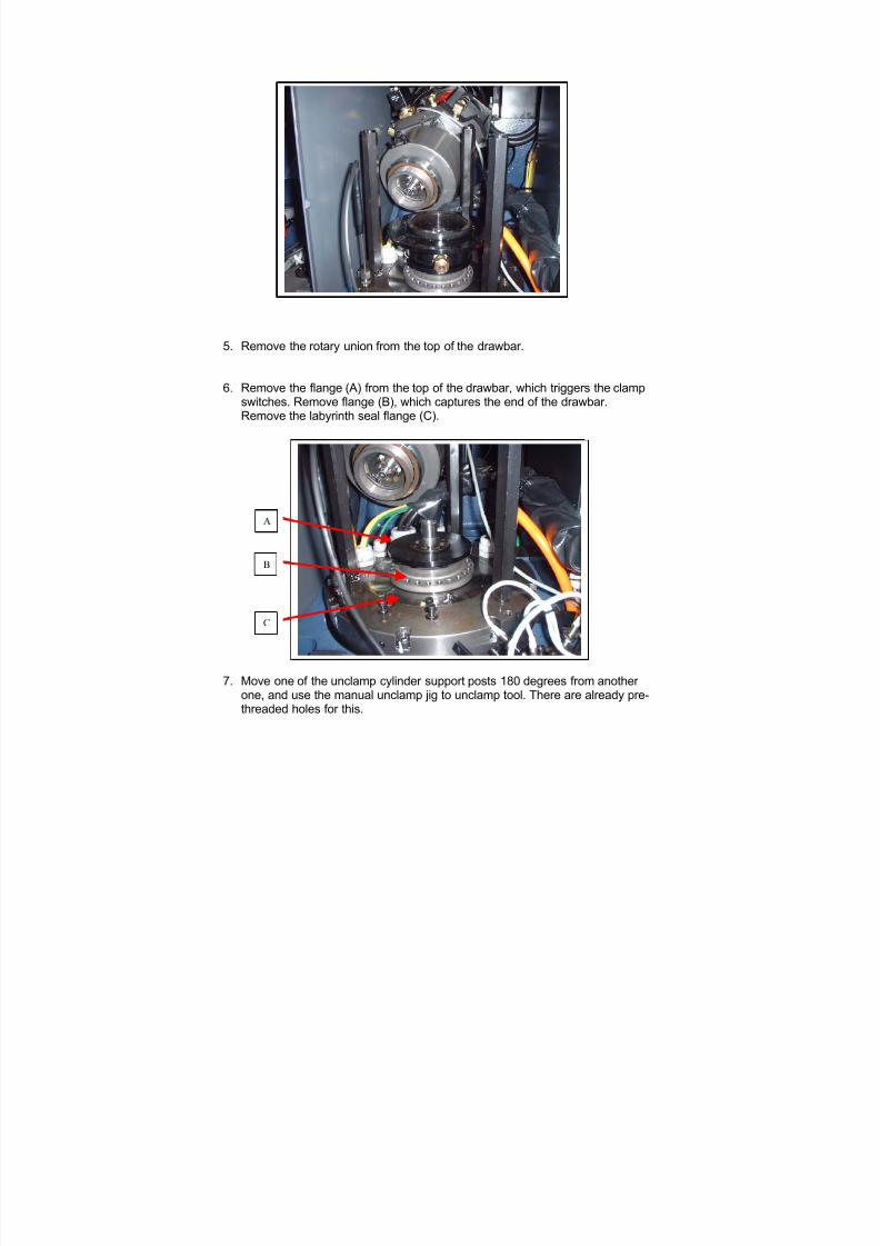
7/21/2019 MORISEIKI MAINTENANCE CLASS
http://slidepdf.com/reader/full/moriseiki-maintenance-class 251/409
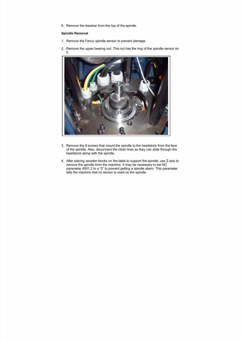
7/21/2019 MORISEIKI MAINTENANCE CLASS
http://slidepdf.com/reader/full/moriseiki-maintenance-class 252/409
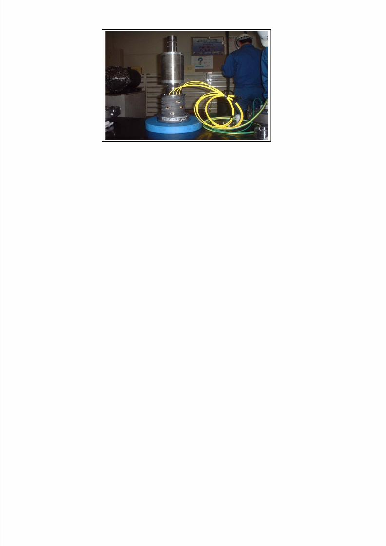
7/21/2019 MORISEIKI MAINTENANCE CLASS
http://slidepdf.com/reader/full/moriseiki-maintenance-class 253/409
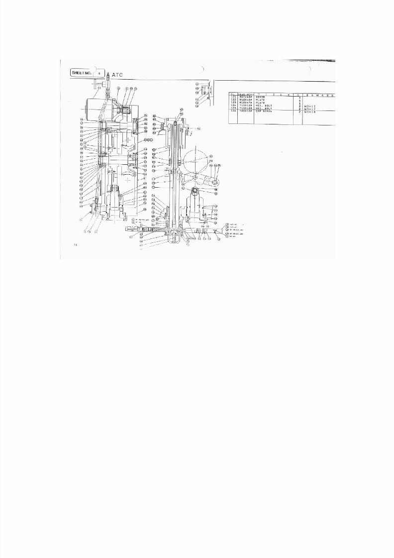
7/21/2019 MORISEIKI MAINTENANCE CLASS
http://slidepdf.com/reader/full/moriseiki-maintenance-class 254/409
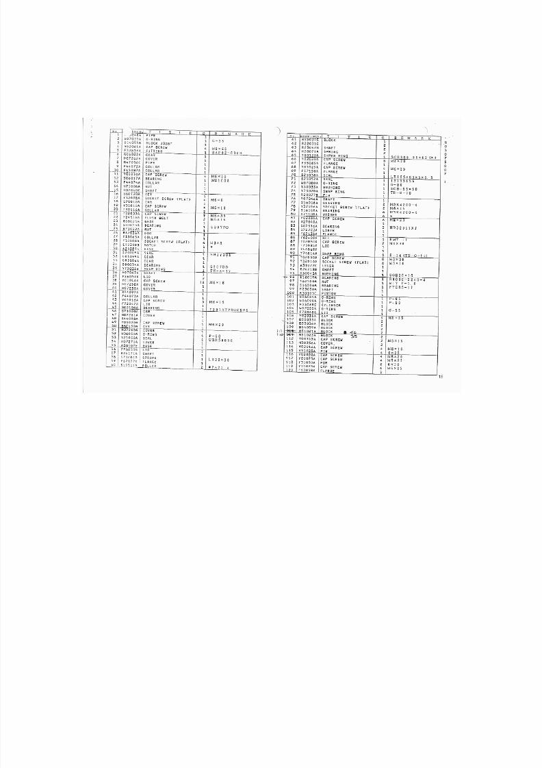
7/21/2019 MORISEIKI MAINTENANCE CLASS
http://slidepdf.com/reader/full/moriseiki-maintenance-class 255/409
7/21/2019 MORISEIKI MAINTENANCE CLASS
http://slidepdf.com/reader/full/moriseiki-maintenance-class 256/409
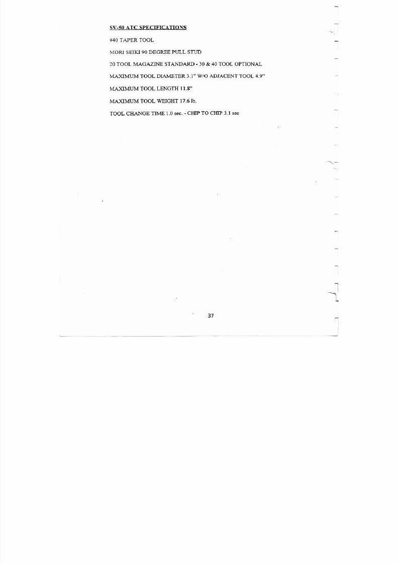
7/21/2019 MORISEIKI MAINTENANCE CLASS
http://slidepdf.com/reader/full/moriseiki-maintenance-class 257/409
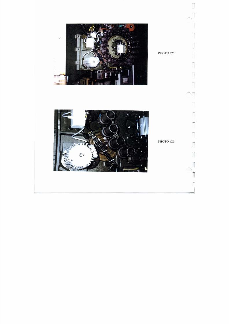
7/21/2019 MORISEIKI MAINTENANCE CLASS
http://slidepdf.com/reader/full/moriseiki-maintenance-class 258/409
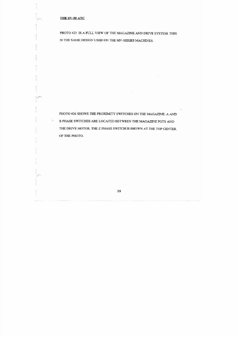
7/21/2019 MORISEIKI MAINTENANCE CLASS
http://slidepdf.com/reader/full/moriseiki-maintenance-class 259/409
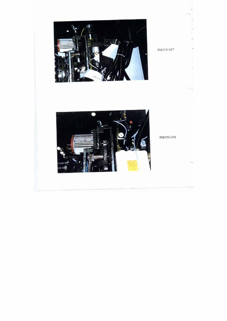
7/21/2019 MORISEIKI MAINTENANCE CLASS
http://slidepdf.com/reader/full/moriseiki-maintenance-class 260/409
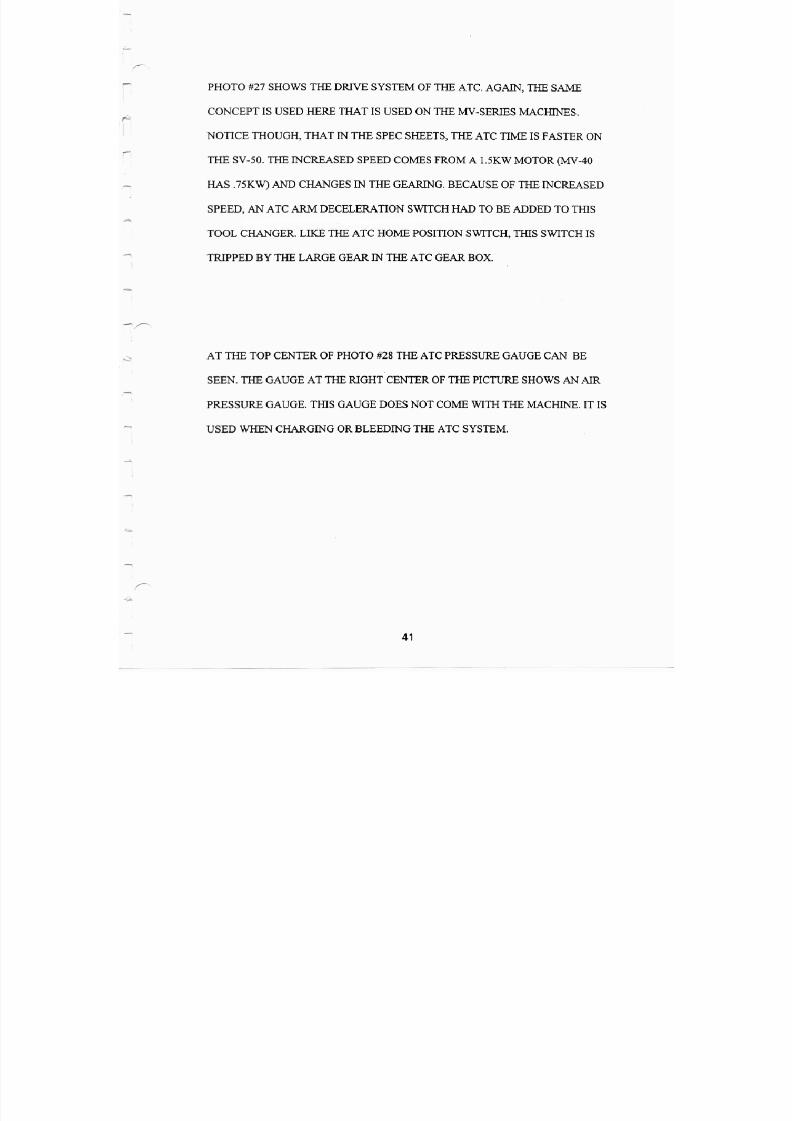
7/21/2019 MORISEIKI MAINTENANCE CLASS
http://slidepdf.com/reader/full/moriseiki-maintenance-class 261/409
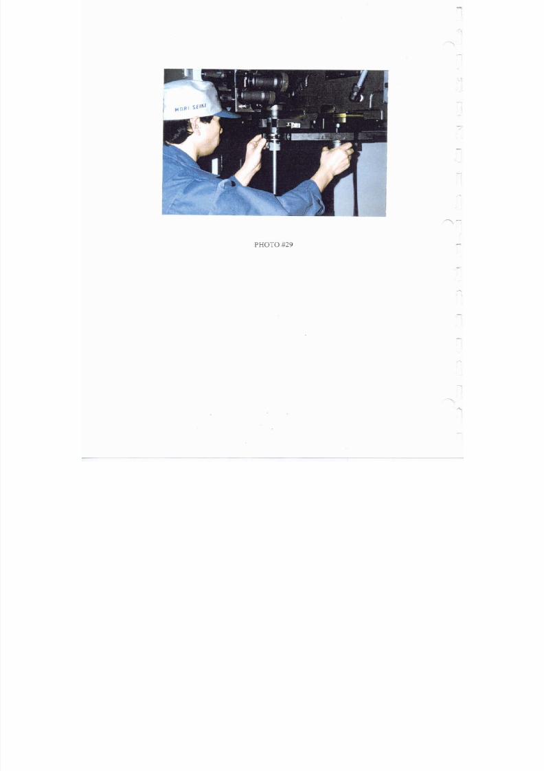
7/21/2019 MORISEIKI MAINTENANCE CLASS
http://slidepdf.com/reader/full/moriseiki-maintenance-class 262/409
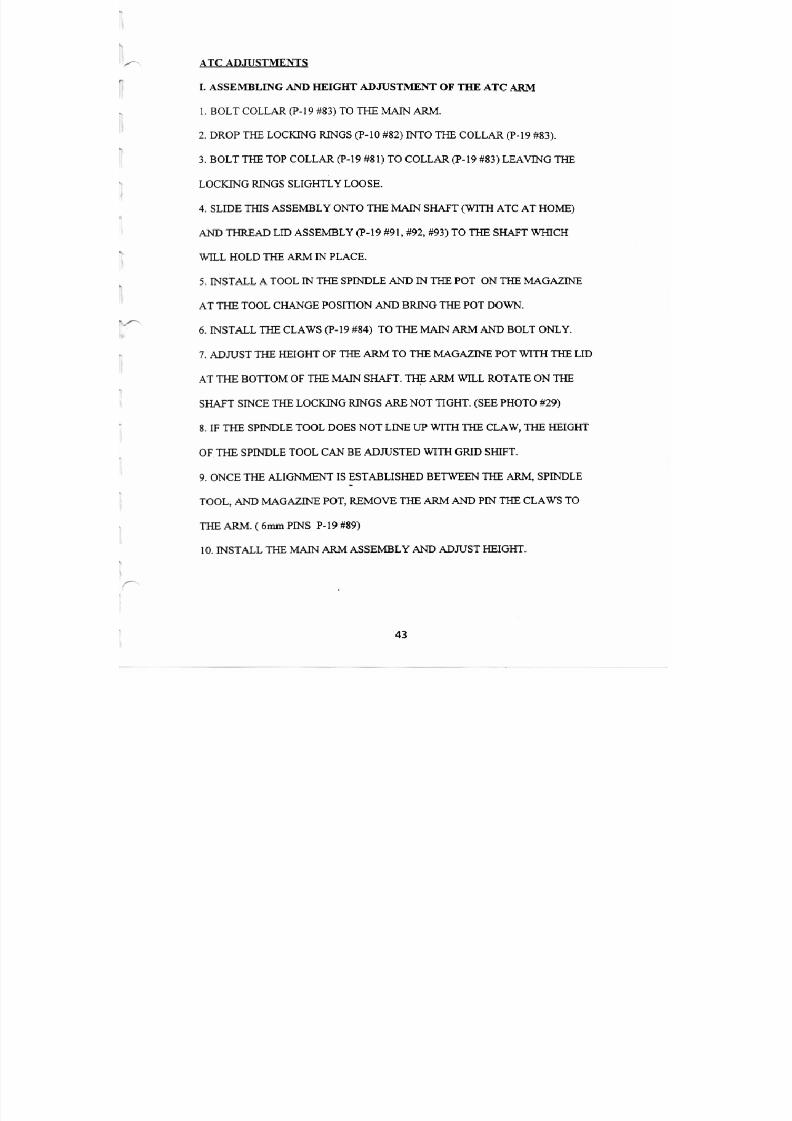
7/21/2019 MORISEIKI MAINTENANCE CLASS
http://slidepdf.com/reader/full/moriseiki-maintenance-class 263/409
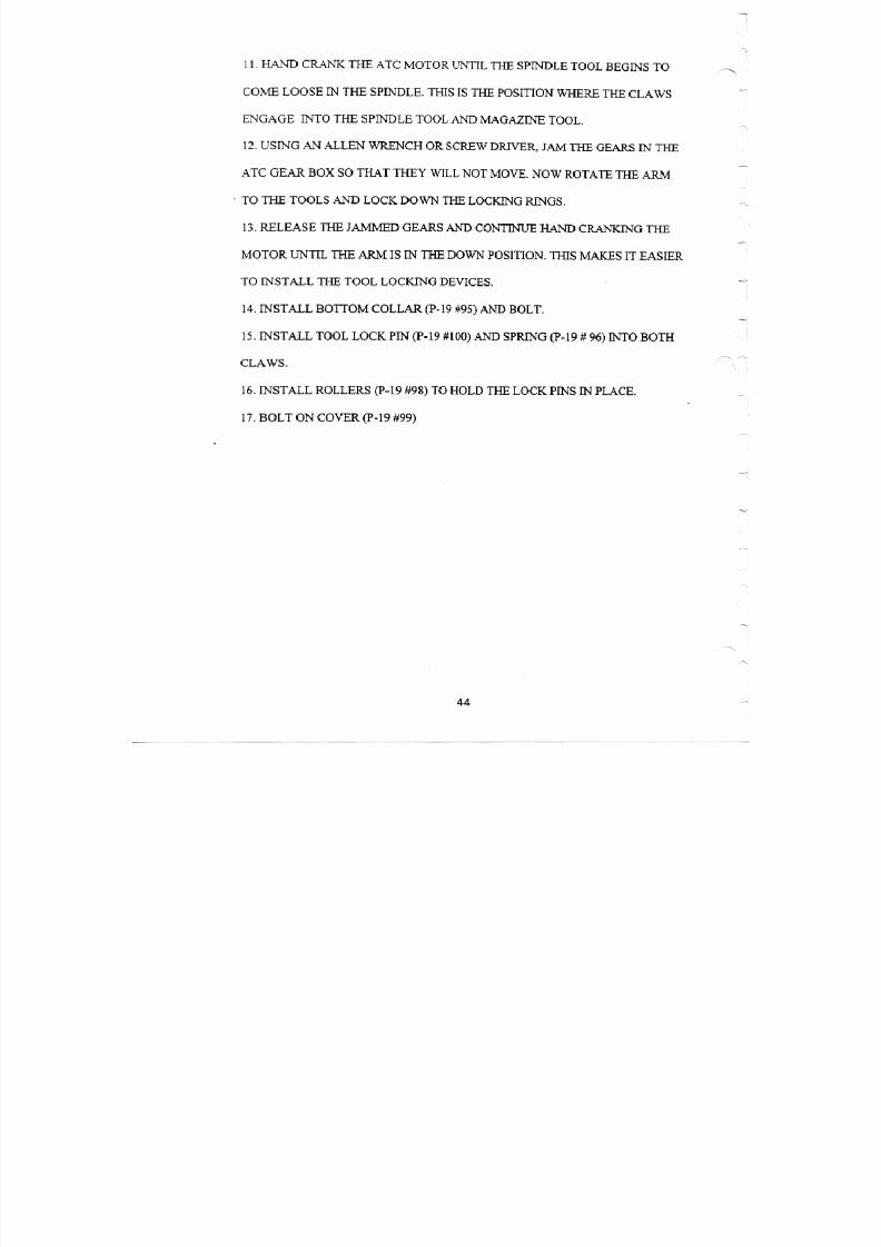
7/21/2019 MORISEIKI MAINTENANCE CLASS
http://slidepdf.com/reader/full/moriseiki-maintenance-class 264/409
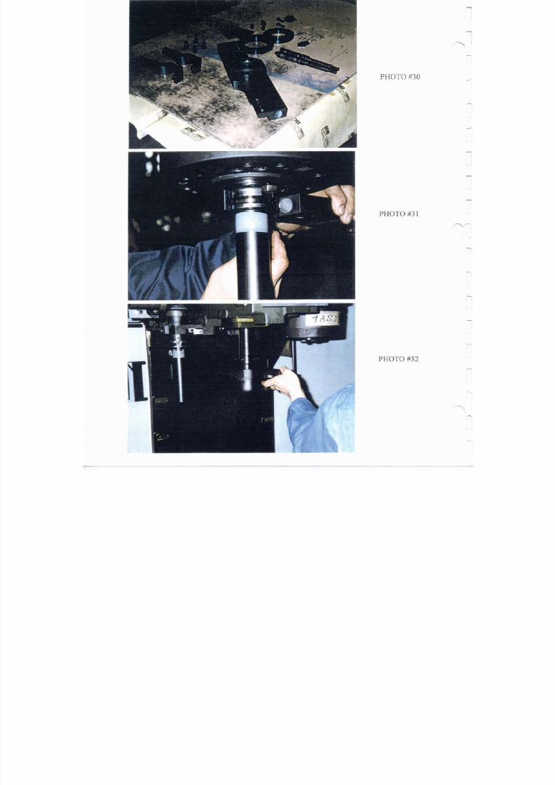
7/21/2019 MORISEIKI MAINTENANCE CLASS
http://slidepdf.com/reader/full/moriseiki-maintenance-class 265/409
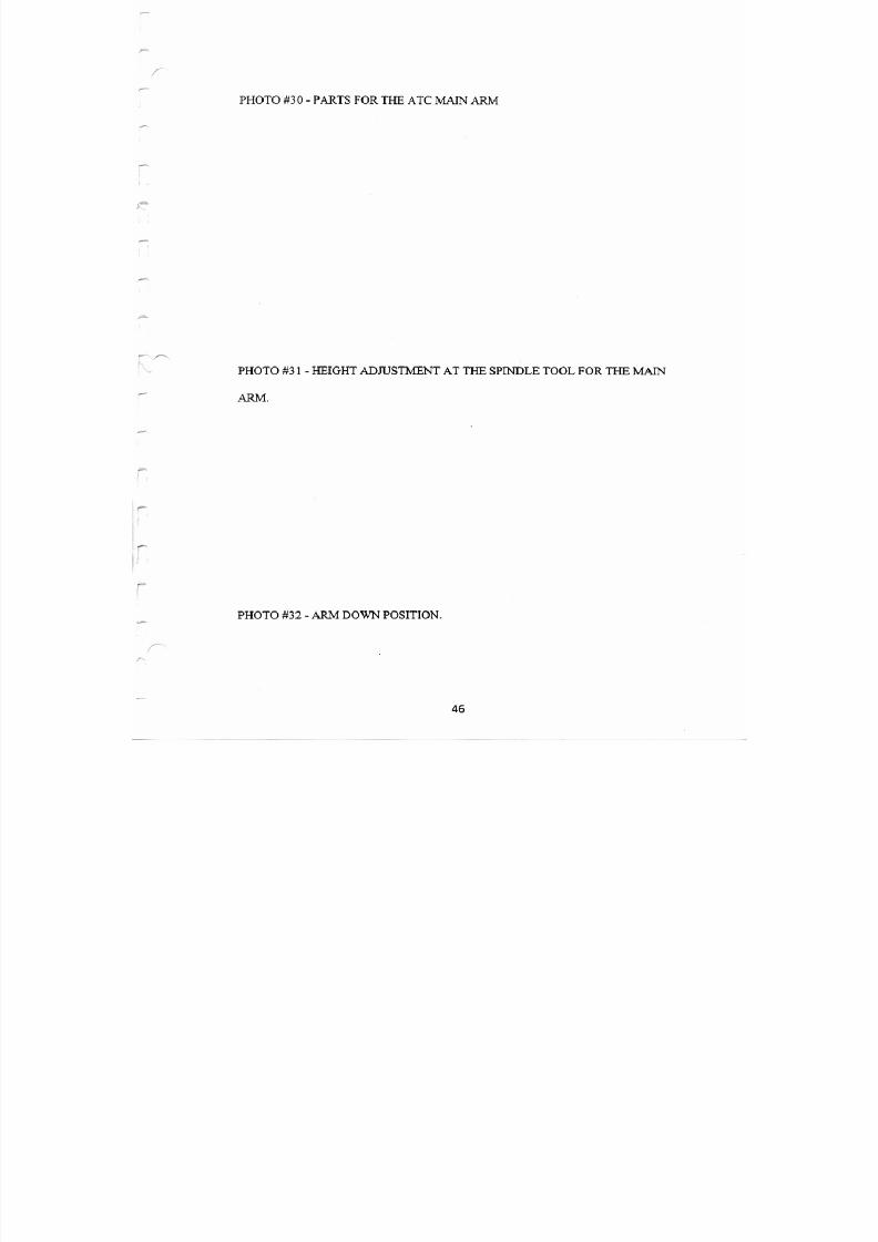
7/21/2019 MORISEIKI MAINTENANCE CLASS
http://slidepdf.com/reader/full/moriseiki-maintenance-class 266/409
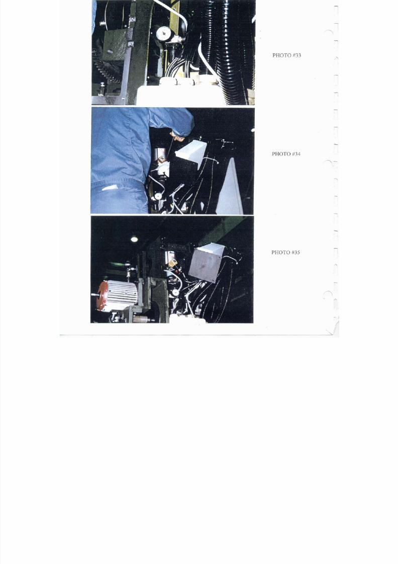
7/21/2019 MORISEIKI MAINTENANCE CLASS
http://slidepdf.com/reader/full/moriseiki-maintenance-class 267/409
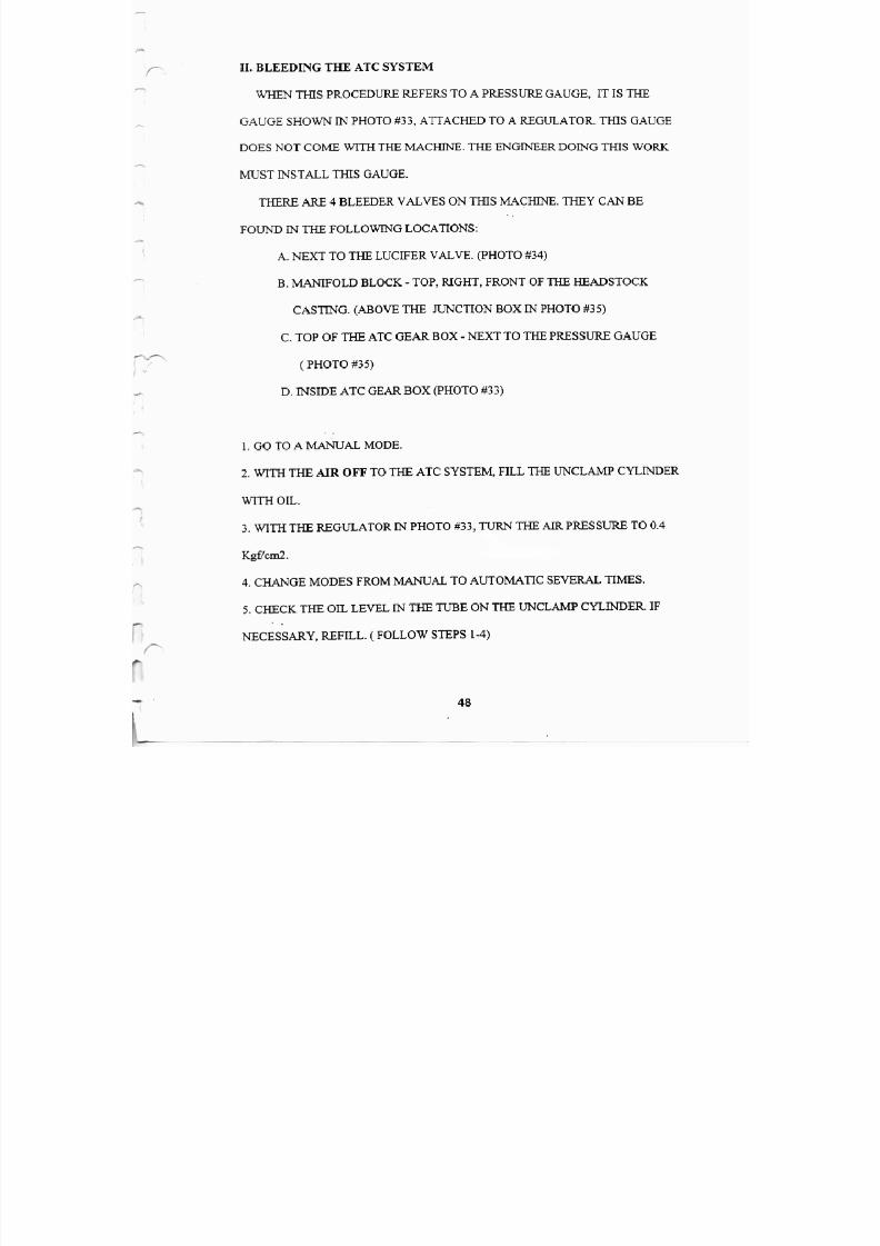
7/21/2019 MORISEIKI MAINTENANCE CLASS
http://slidepdf.com/reader/full/moriseiki-maintenance-class 268/409
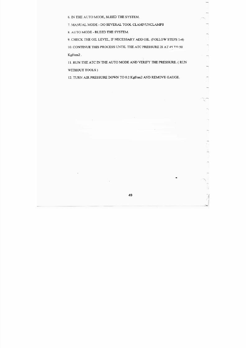
7/21/2019 MORISEIKI MAINTENANCE CLASS
http://slidepdf.com/reader/full/moriseiki-maintenance-class 269/409
7/21/2019 MORISEIKI MAINTENANCE CLASS
http://slidepdf.com/reader/full/moriseiki-maintenance-class 270/409
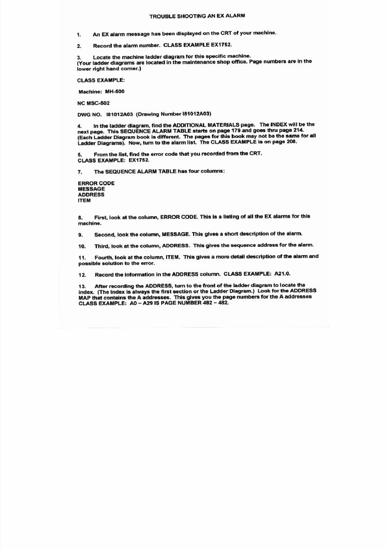
7/21/2019 MORISEIKI MAINTENANCE CLASS
http://slidepdf.com/reader/full/moriseiki-maintenance-class 271/409
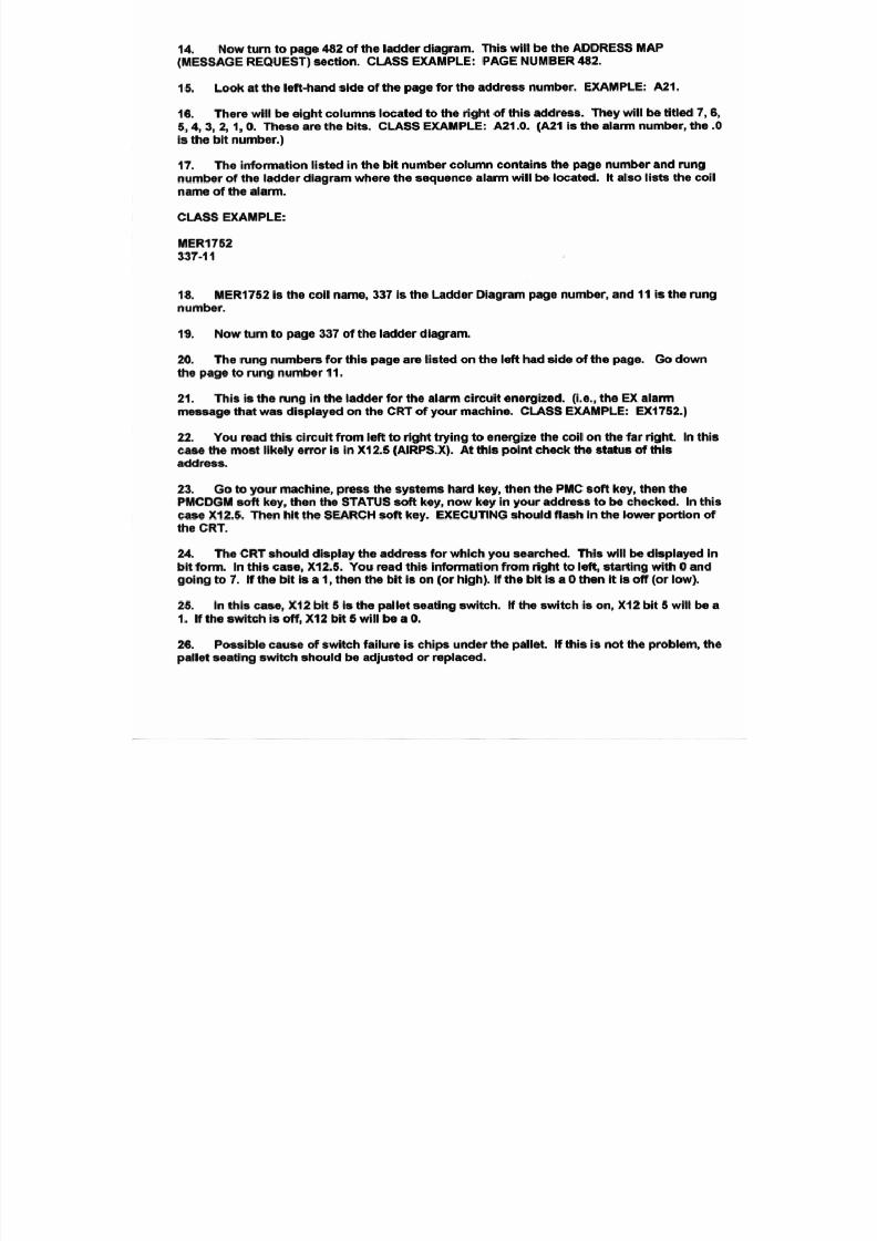
7/21/2019 MORISEIKI MAINTENANCE CLASS
http://slidepdf.com/reader/full/moriseiki-maintenance-class 272/409
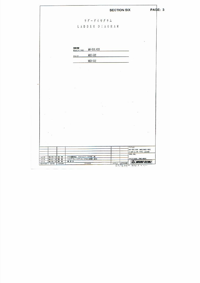
7/21/2019 MORISEIKI MAINTENANCE CLASS
http://slidepdf.com/reader/full/moriseiki-maintenance-class 273/409
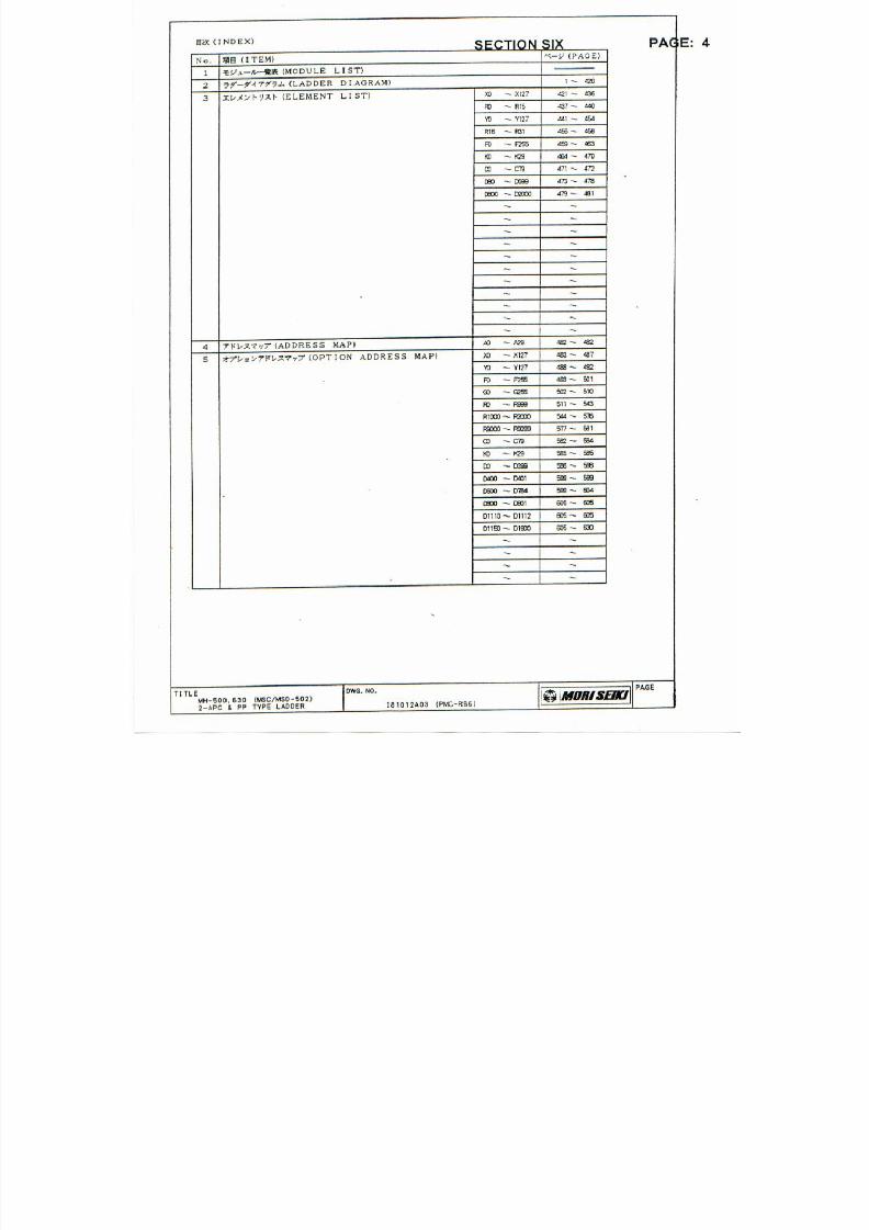
7/21/2019 MORISEIKI MAINTENANCE CLASS
http://slidepdf.com/reader/full/moriseiki-maintenance-class 274/409

7/21/2019 MORISEIKI MAINTENANCE CLASS
http://slidepdf.com/reader/full/moriseiki-maintenance-class 275/409
7/21/2019 MORISEIKI MAINTENANCE CLASS
http://slidepdf.com/reader/full/moriseiki-maintenance-class 276/409
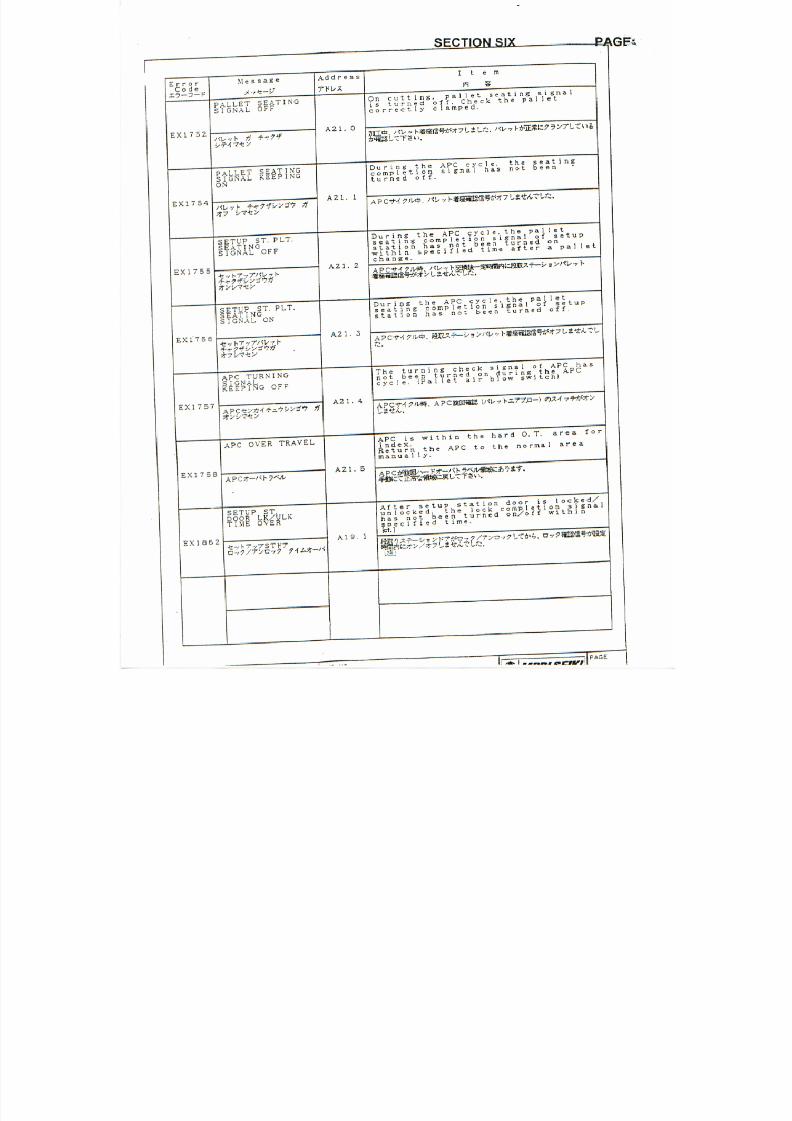
7/21/2019 MORISEIKI MAINTENANCE CLASS
http://slidepdf.com/reader/full/moriseiki-maintenance-class 277/409
7/21/2019 MORISEIKI MAINTENANCE CLASS
http://slidepdf.com/reader/full/moriseiki-maintenance-class 278/409
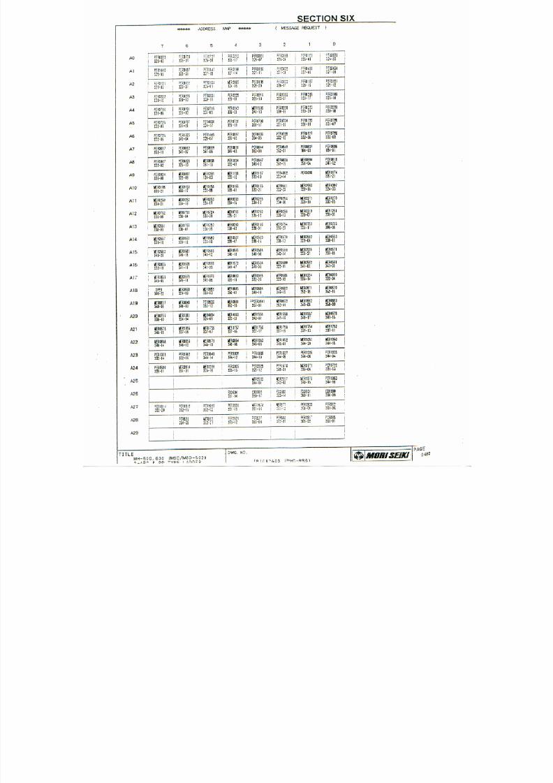
7/21/2019 MORISEIKI MAINTENANCE CLASS
http://slidepdf.com/reader/full/moriseiki-maintenance-class 279/409
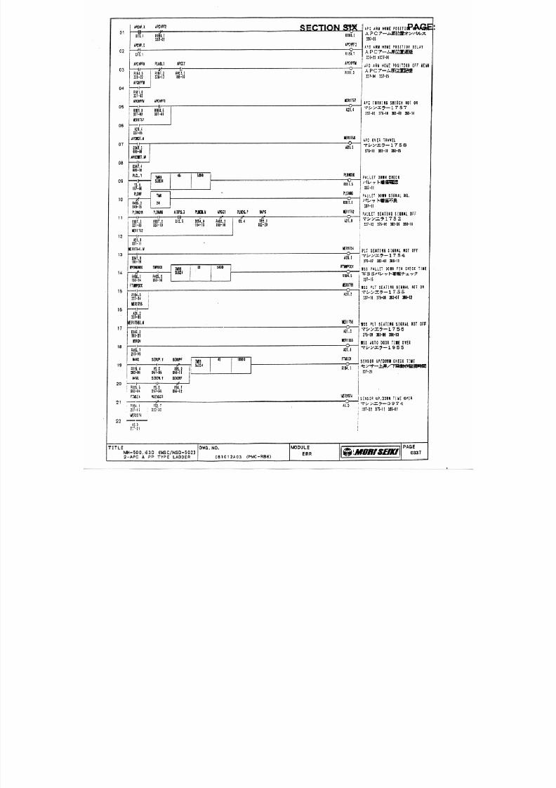
7/21/2019 MORISEIKI MAINTENANCE CLASS
http://slidepdf.com/reader/full/moriseiki-maintenance-class 280/409
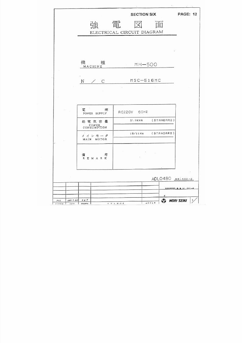
7/21/2019 MORISEIKI MAINTENANCE CLASS
http://slidepdf.com/reader/full/moriseiki-maintenance-class 281/409

7/21/2019 MORISEIKI MAINTENANCE CLASS
http://slidepdf.com/reader/full/moriseiki-maintenance-class 282/409
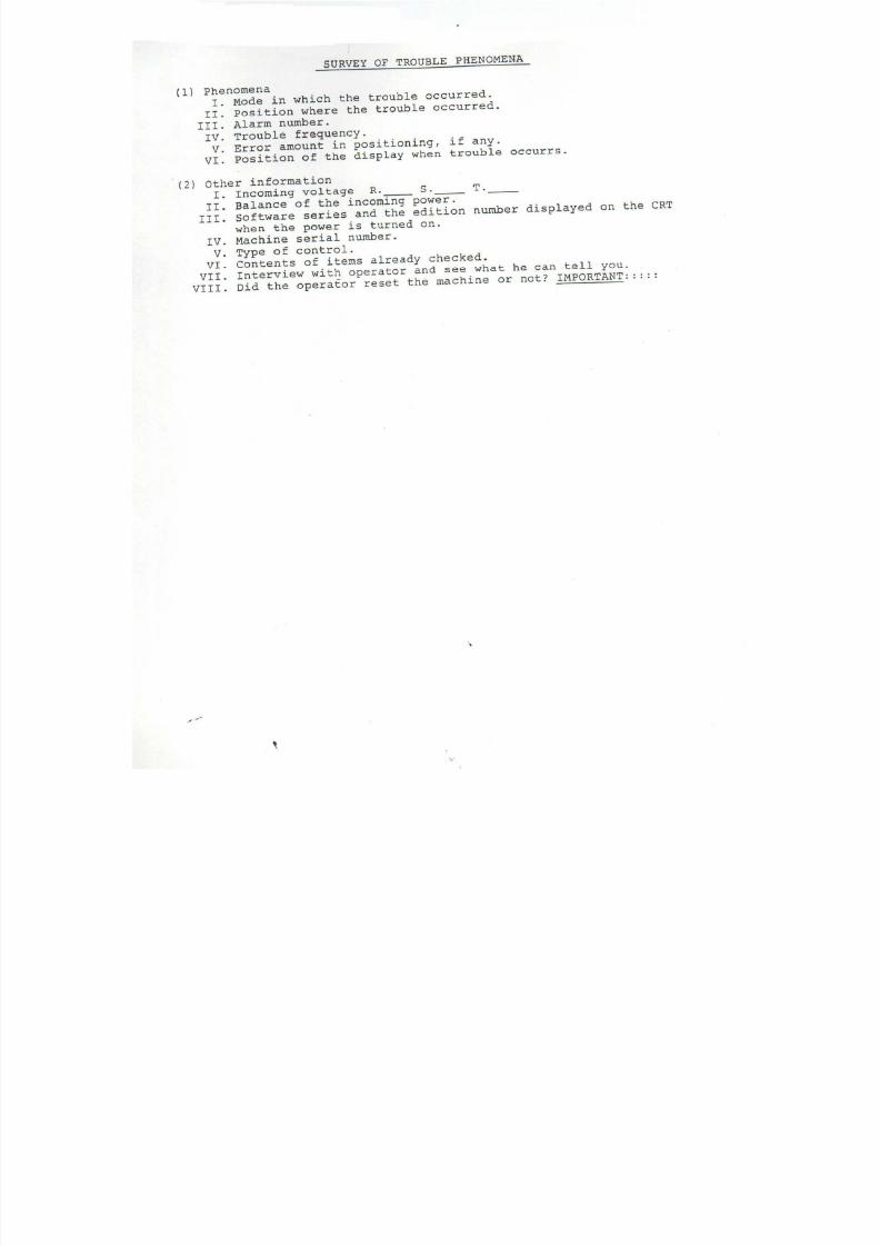
7/21/2019 MORISEIKI MAINTENANCE CLASS
http://slidepdf.com/reader/full/moriseiki-maintenance-class 283/409
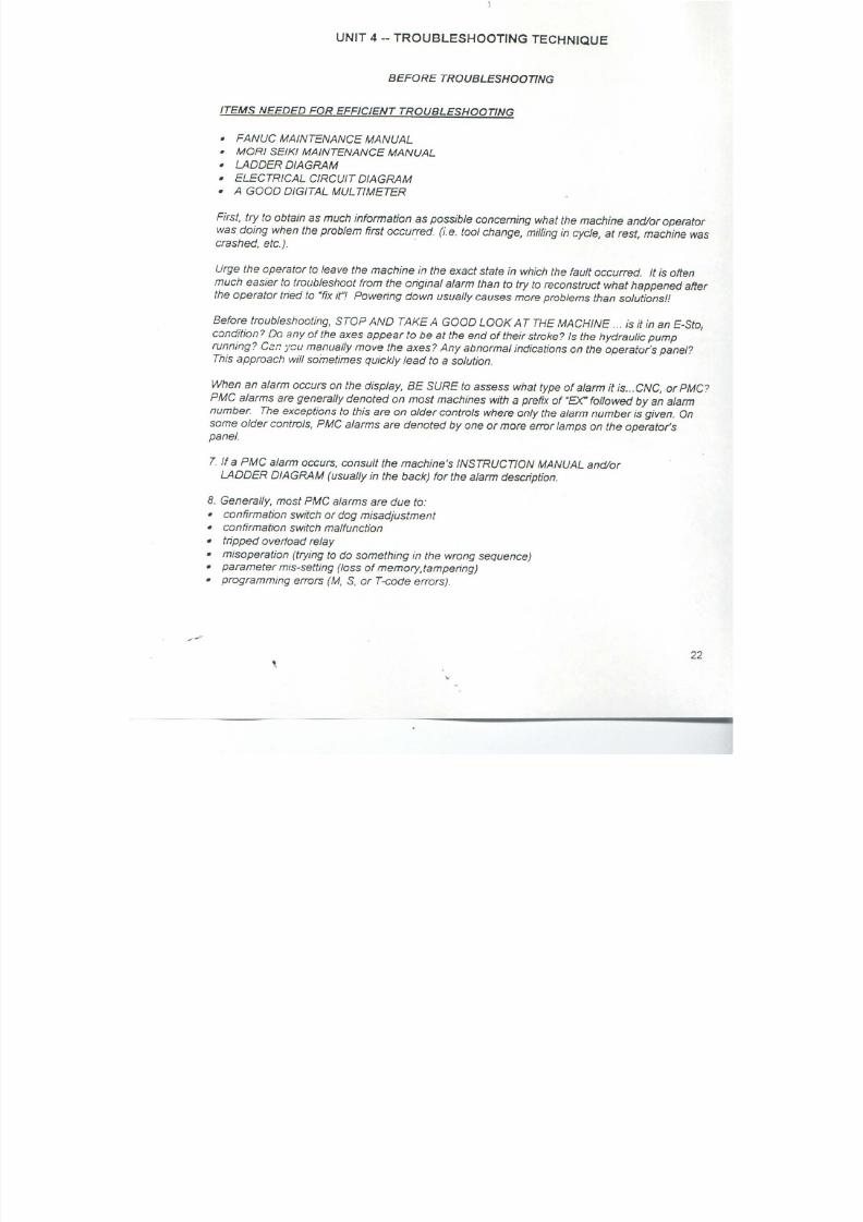
7/21/2019 MORISEIKI MAINTENANCE CLASS
http://slidepdf.com/reader/full/moriseiki-maintenance-class 284/409
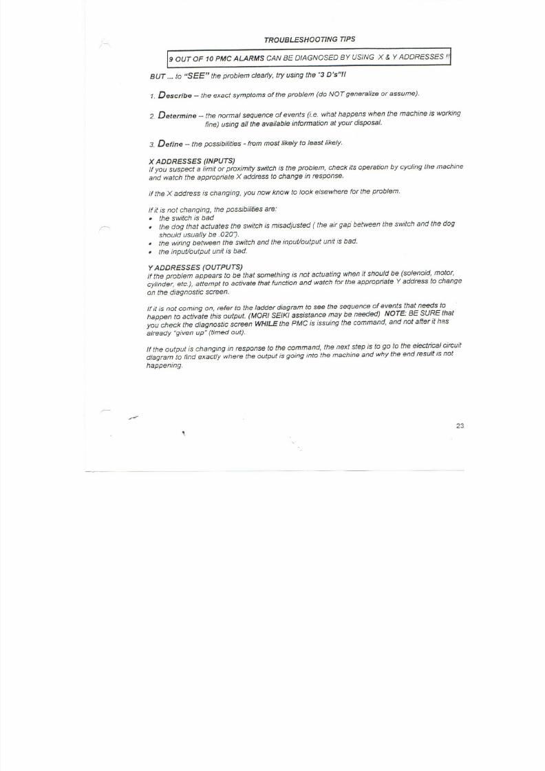
7/21/2019 MORISEIKI MAINTENANCE CLASS
http://slidepdf.com/reader/full/moriseiki-maintenance-class 285/409
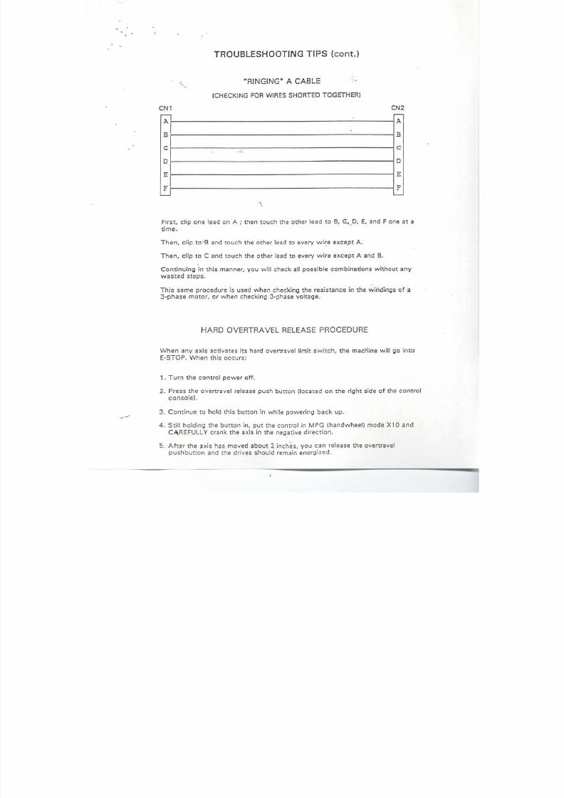
7/21/2019 MORISEIKI MAINTENANCE CLASS
http://slidepdf.com/reader/full/moriseiki-maintenance-class 286/409
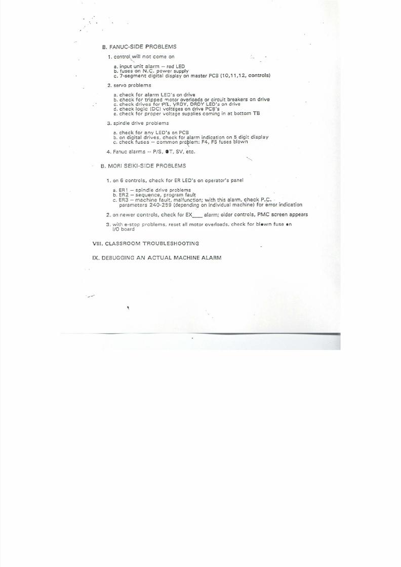
7/21/2019 MORISEIKI MAINTENANCE CLASS
http://slidepdf.com/reader/full/moriseiki-maintenance-class 287/409
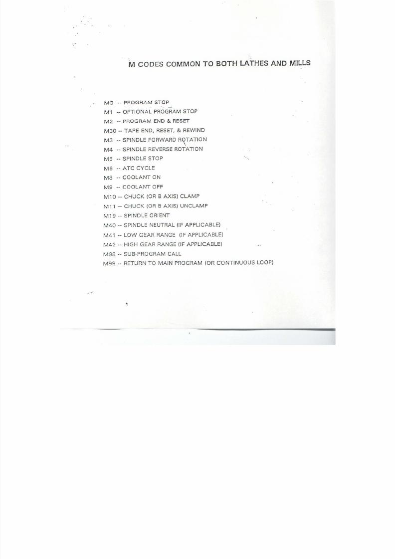
7/21/2019 MORISEIKI MAINTENANCE CLASS
http://slidepdf.com/reader/full/moriseiki-maintenance-class 288/409
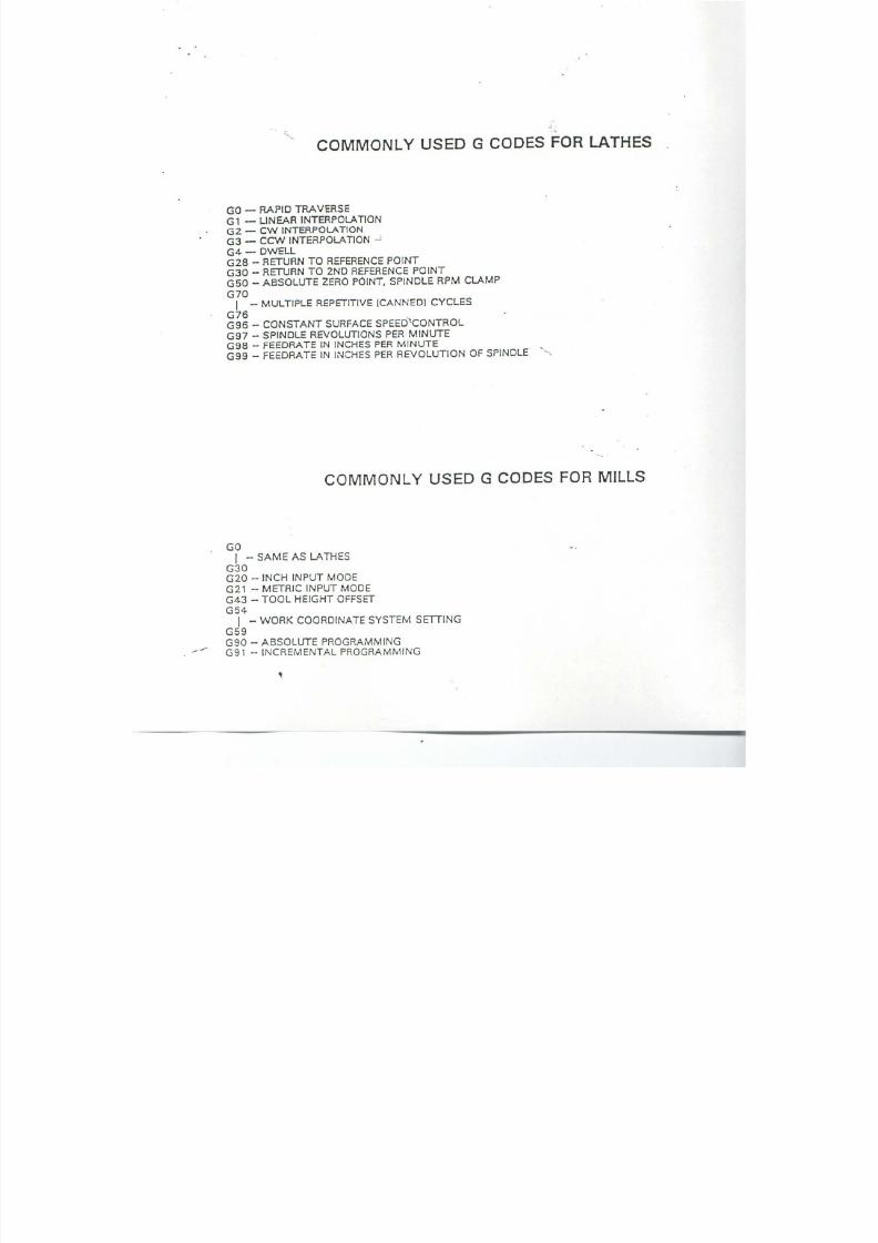
7/21/2019 MORISEIKI MAINTENANCE CLASS
http://slidepdf.com/reader/full/moriseiki-maintenance-class 289/409

7/21/2019 MORISEIKI MAINTENANCE CLASS
http://slidepdf.com/reader/full/moriseiki-maintenance-class 290/409
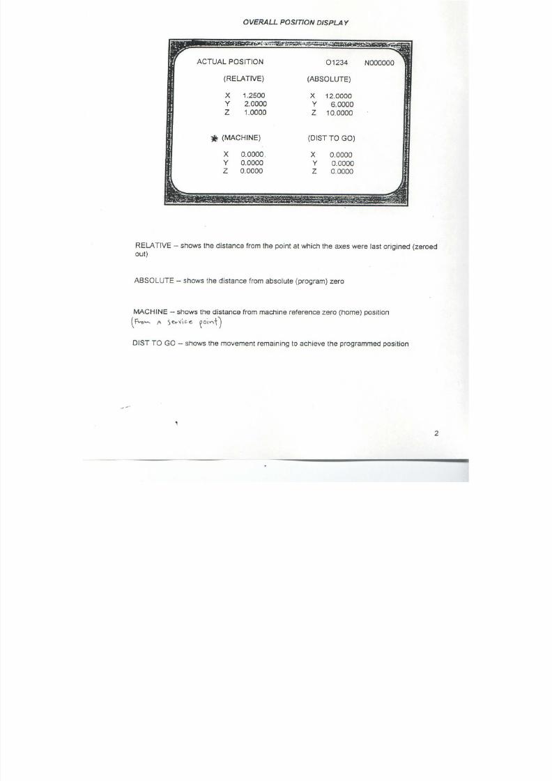
7/21/2019 MORISEIKI MAINTENANCE CLASS
http://slidepdf.com/reader/full/moriseiki-maintenance-class 291/409
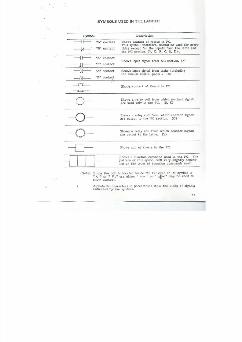
7/21/2019 MORISEIKI MAINTENANCE CLASS
http://slidepdf.com/reader/full/moriseiki-maintenance-class 292/409
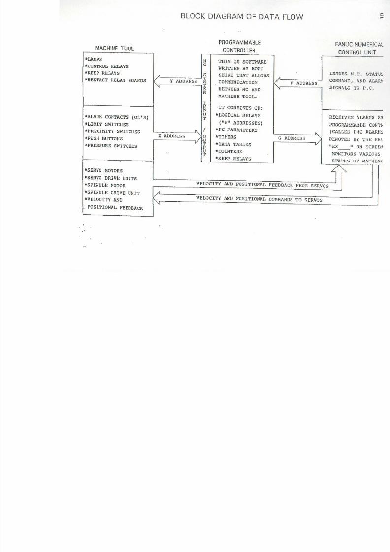
7/21/2019 MORISEIKI MAINTENANCE CLASS
http://slidepdf.com/reader/full/moriseiki-maintenance-class 293/409
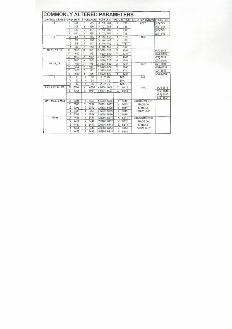
7/21/2019 MORISEIKI MAINTENANCE CLASS
http://slidepdf.com/reader/full/moriseiki-maintenance-class 294/409

7/21/2019 MORISEIKI MAINTENANCE CLASS
http://slidepdf.com/reader/full/moriseiki-maintenance-class 295/409
LADDER AND DIAGNOSTICS
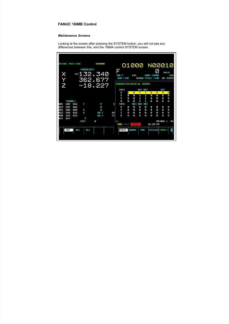
7/21/2019 MORISEIKI MAINTENANCE CLASS
http://slidepdf.com/reader/full/moriseiki-maintenance-class 296/409
FANUC 18iMB Control
Maintenance Screens
Looking at the screen after pressing the SYSTEM button, you will not see anydifferences between this, and the 18iMA control SYSTEM screen.
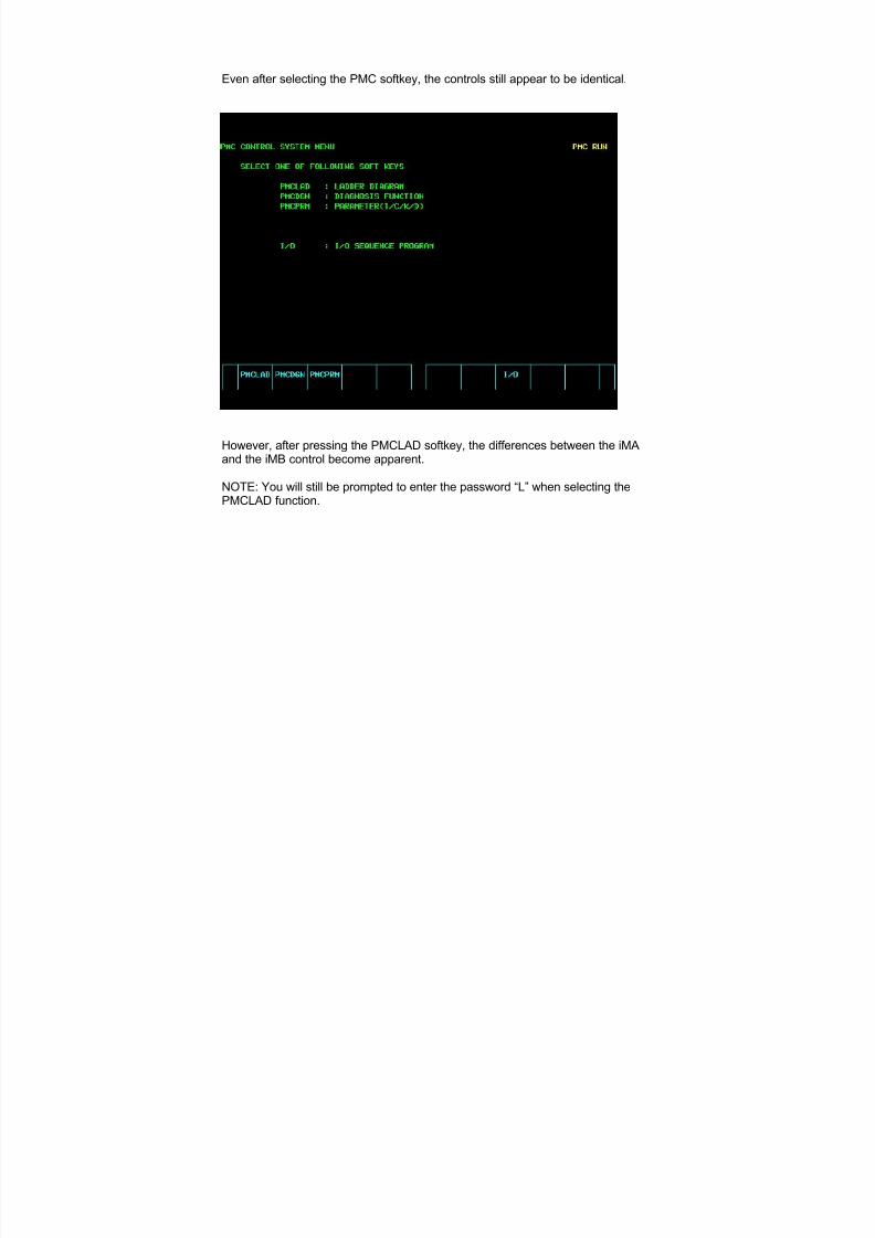
7/21/2019 MORISEIKI MAINTENANCE CLASS
http://slidepdf.com/reader/full/moriseiki-maintenance-class 297/409
Even after selecting the PMC softkey, the controls still appear to be identical.
However, after pressing the PMCLAD softkey, the differences between the iMA
and the iMB control become apparent.
NOTE: You will still be prompted to enter the password “L” when selecting thePMCLAD function.
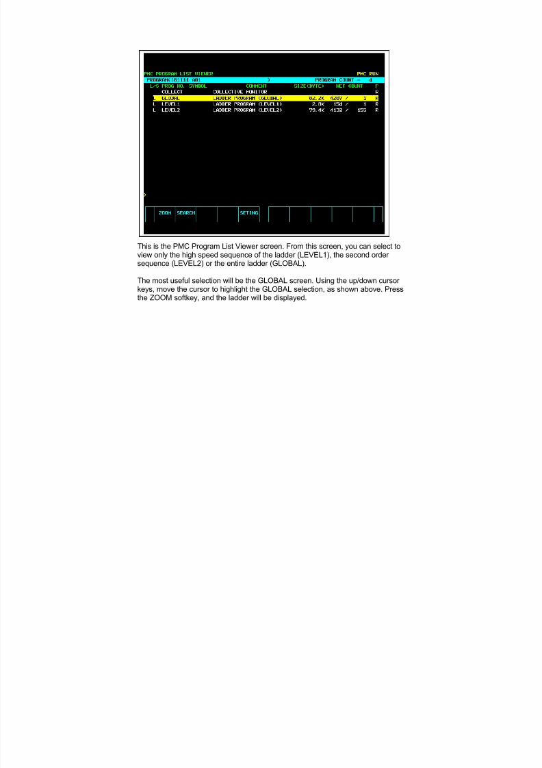
7/21/2019 MORISEIKI MAINTENANCE CLASS
http://slidepdf.com/reader/full/moriseiki-maintenance-class 298/409
This is the PMC Program List Viewer screen. From this screen, you can select toview only the high speed sequence of the ladder (LEVEL1), the second order sequence (LEVEL2) or the entire ladder (GLOBAL).
The most useful selection will be the GLOBAL screen. Using the up/down cursor keys, move the cursor to highlight the GLOBAL selection, as shown above. Pressthe ZOOM softkey, and the ladder will be displayed.
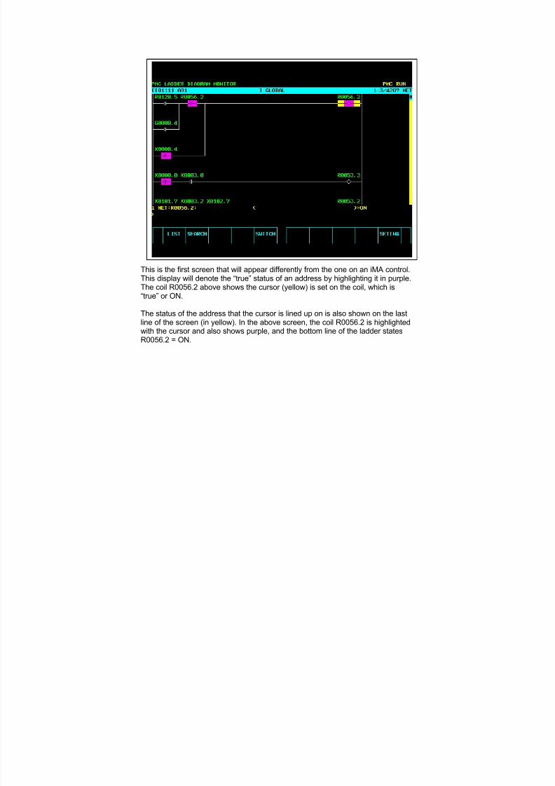
7/21/2019 MORISEIKI MAINTENANCE CLASS
http://slidepdf.com/reader/full/moriseiki-maintenance-class 299/409
This is the first screen that will appear differently from the one on an iMA control.This display will denote the “true” status of an address by highlighting it in purple.The coil R0056.2 above shows the cursor (yellow) is set on the coil, which is“true” or ON.
The status of the address that the cursor is lined up on is also shown on the lastline of the screen (in yellow). In the above screen, the coil R0056.2 is highlightedwith the cursor and also shows purple, and the bottom line of the ladder statesR0056.2 = ON.

7/21/2019 MORISEIKI MAINTENANCE CLASS
http://slidepdf.com/reader/full/moriseiki-maintenance-class 300/409
In the screen displayed above, note that the cursor is set on the coil R0053.3.Since the address X0003.0 is not “true” (ON), there is no purple showing onR0053.3. The bottom line also clearly shows that R0053.3 is OFF.
All iMB controls will display the ladder in this manner.
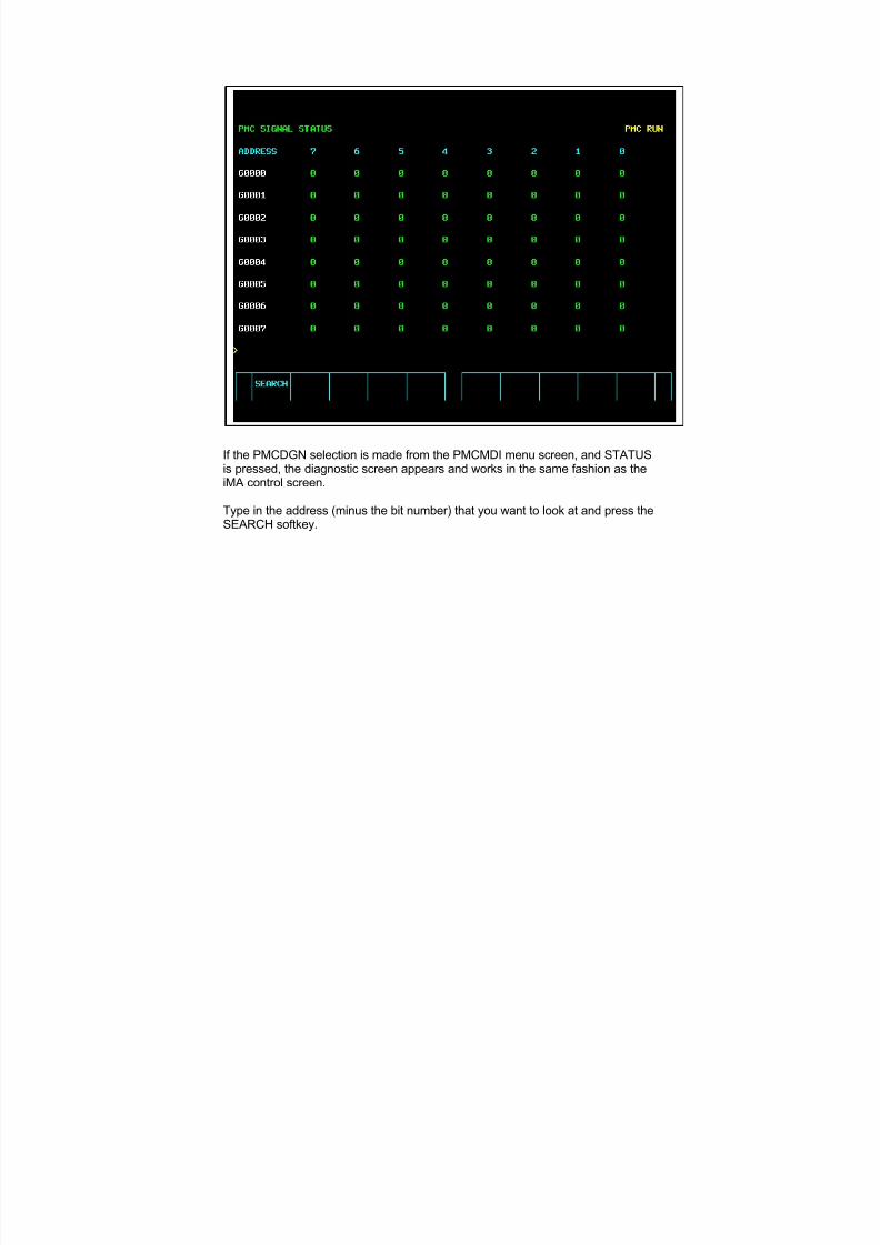
7/21/2019 MORISEIKI MAINTENANCE CLASS
http://slidepdf.com/reader/full/moriseiki-maintenance-class 301/409
If the PMCDGN selection is made from the PMCMDI menu screen, and STATUSis pressed, the diagnostic screen appears and works in the same fashion as theiMA control screen.
Type in the address (minus the bit number) that you want to look at and press theSEARCH softkey.
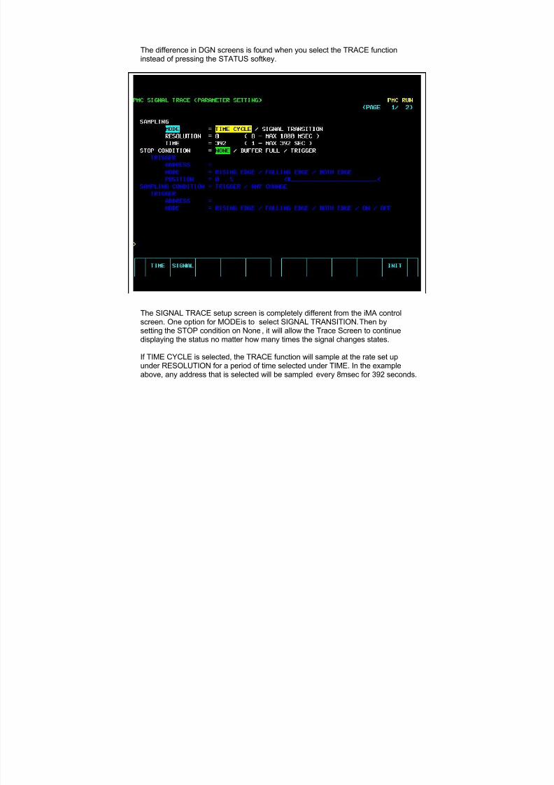
7/21/2019 MORISEIKI MAINTENANCE CLASS
http://slidepdf.com/reader/full/moriseiki-maintenance-class 302/409
The difference in DGN screens is found when you select the TRACE functioninstead of pressing the STATUS softkey.
The SIGNAL TRACE setup screen is completely different from the iMA controlscreen. One option for MODE is to select SIGNAL TRANSITION. Then bysetting the STOP condition on None, it will allow the Trace Screen to continuedisplaying the status no matter how many times the signal changes states.
If TIME CYCLE is selected, the TRACE function will sample at the rate set upunder RESOLUTION for a period of time selected under TIME. In the exampleabove, any address that is selected will be sampled every 8msec for 392 seconds.
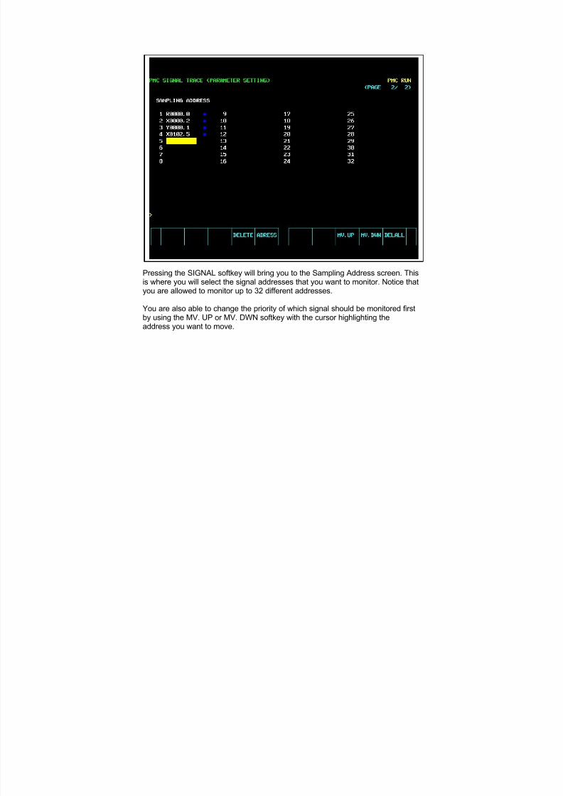
7/21/2019 MORISEIKI MAINTENANCE CLASS
http://slidepdf.com/reader/full/moriseiki-maintenance-class 303/409
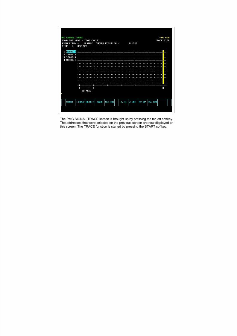
7/21/2019 MORISEIKI MAINTENANCE CLASS
http://slidepdf.com/reader/full/moriseiki-maintenance-class 304/409
The PMC SIGNAL TRACE screen is brought up by pressing the far left softkey.The addresses that were selected on the previous screen are now displayed onthis screen. The TRACE function is started by pressing the START softkey.
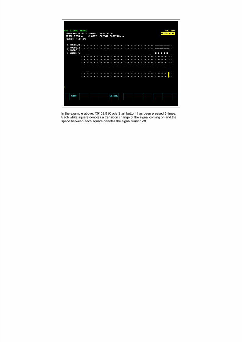
7/21/2019 MORISEIKI MAINTENANCE CLASS
http://slidepdf.com/reader/full/moriseiki-maintenance-class 305/409
In the example above, X0102.5 (Cycle Start button) has been pressed 5 times.Each white square denotes a transition change of the signal coming on and thespace between each square denotes the signal turning off.
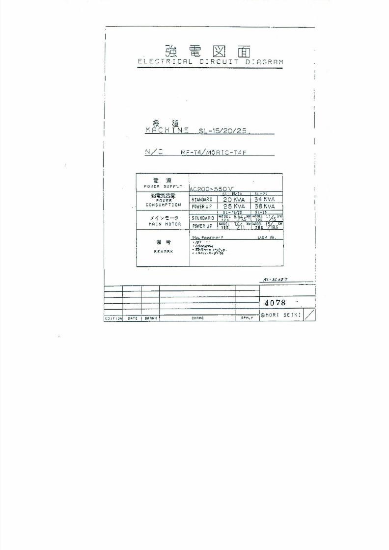
7/21/2019 MORISEIKI MAINTENANCE CLASS
http://slidepdf.com/reader/full/moriseiki-maintenance-class 306/409
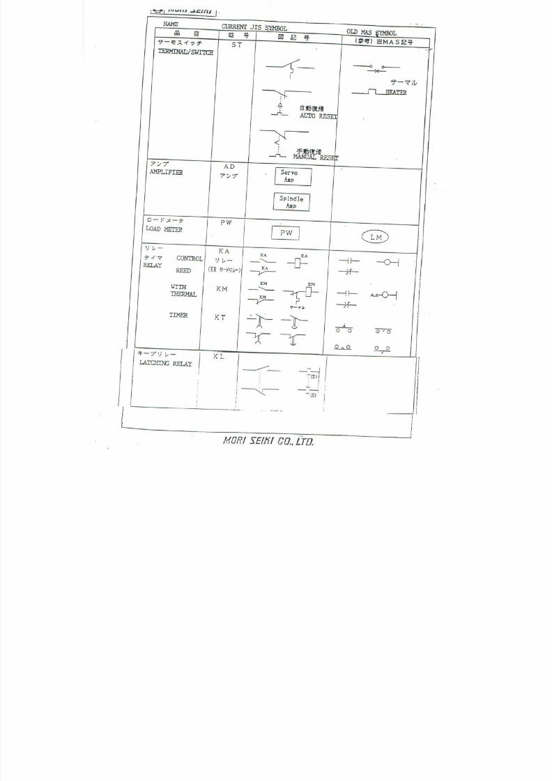
7/21/2019 MORISEIKI MAINTENANCE CLASS
http://slidepdf.com/reader/full/moriseiki-maintenance-class 307/409
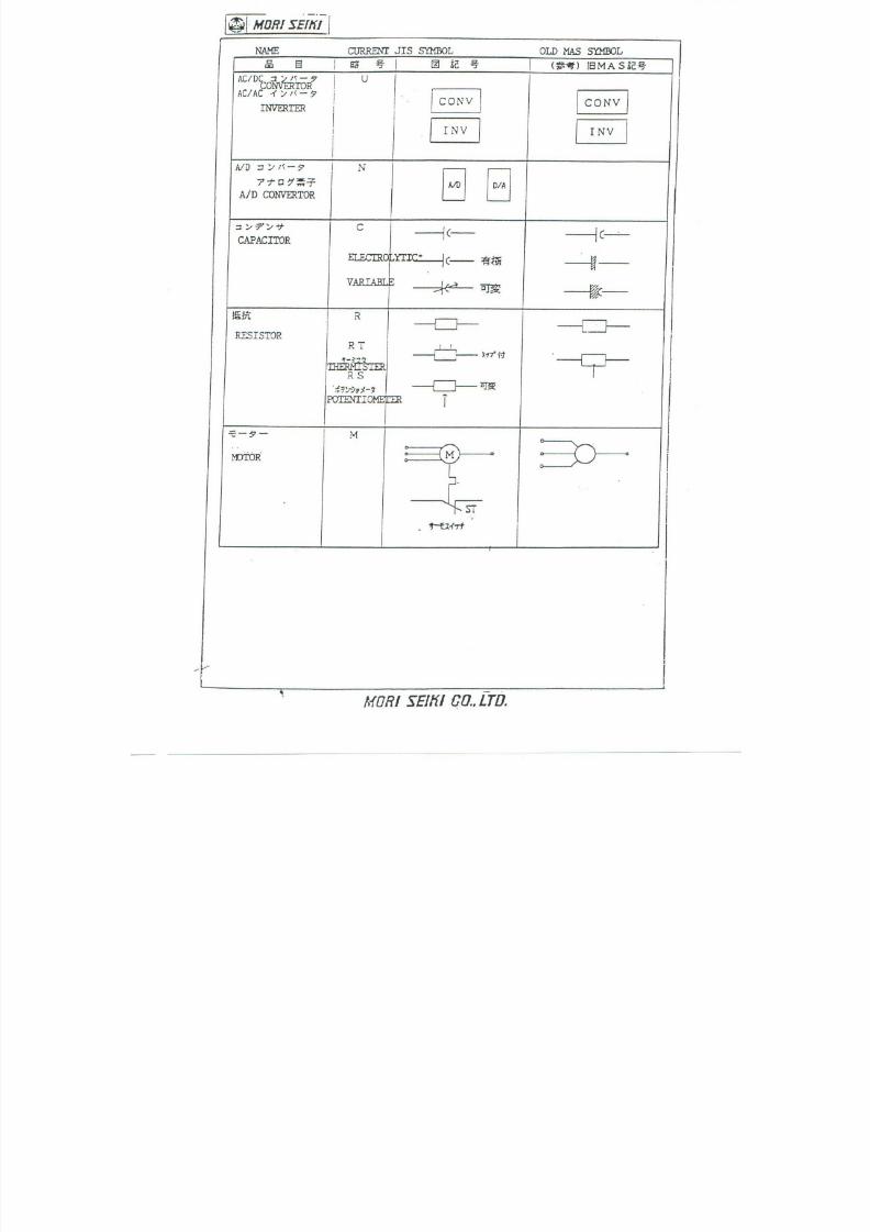
7/21/2019 MORISEIKI MAINTENANCE CLASS
http://slidepdf.com/reader/full/moriseiki-maintenance-class 308/409
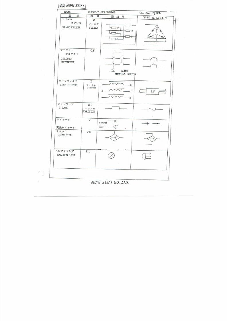
7/21/2019 MORISEIKI MAINTENANCE CLASS
http://slidepdf.com/reader/full/moriseiki-maintenance-class 309/409
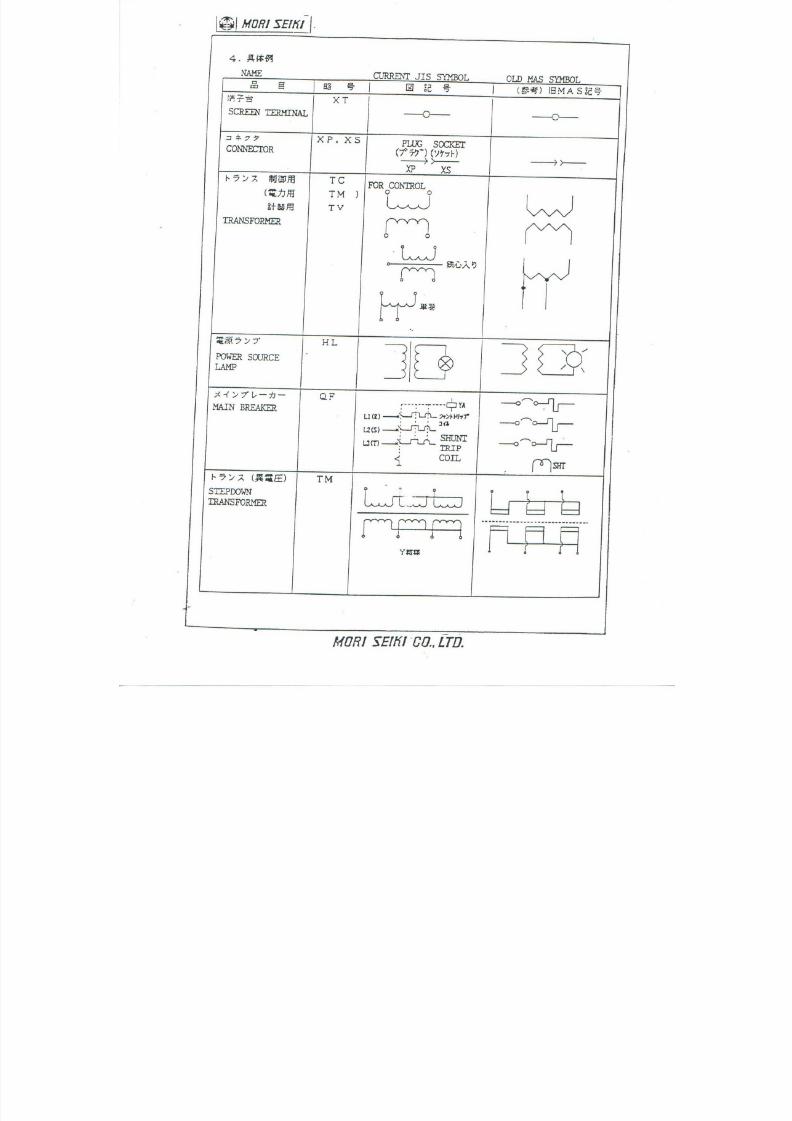
7/21/2019 MORISEIKI MAINTENANCE CLASS
http://slidepdf.com/reader/full/moriseiki-maintenance-class 310/409
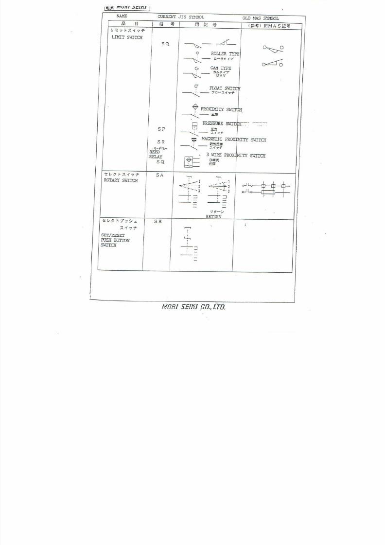
7/21/2019 MORISEIKI MAINTENANCE CLASS
http://slidepdf.com/reader/full/moriseiki-maintenance-class 311/409
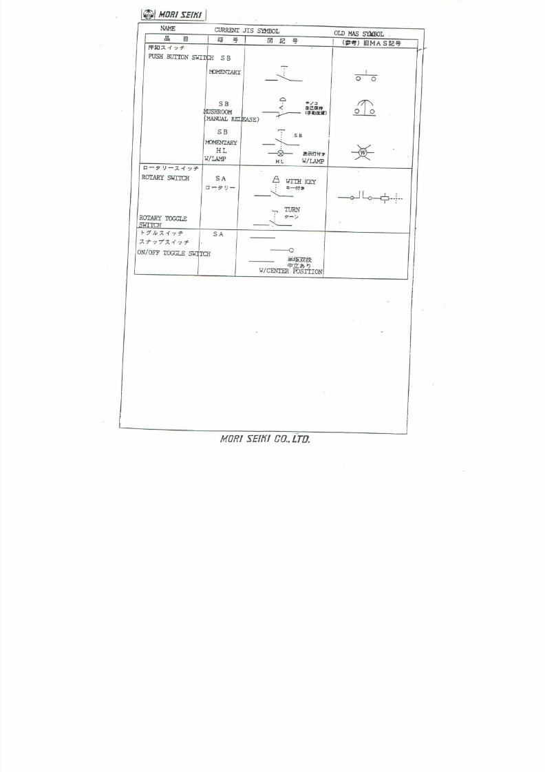
7/21/2019 MORISEIKI MAINTENANCE CLASS
http://slidepdf.com/reader/full/moriseiki-maintenance-class 312/409
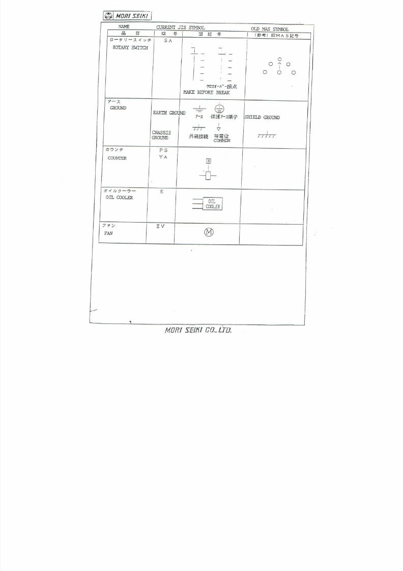
7/21/2019 MORISEIKI MAINTENANCE CLASS
http://slidepdf.com/reader/full/moriseiki-maintenance-class 313/409

7/21/2019 MORISEIKI MAINTENANCE CLASS
http://slidepdf.com/reader/full/moriseiki-maintenance-class 314/409
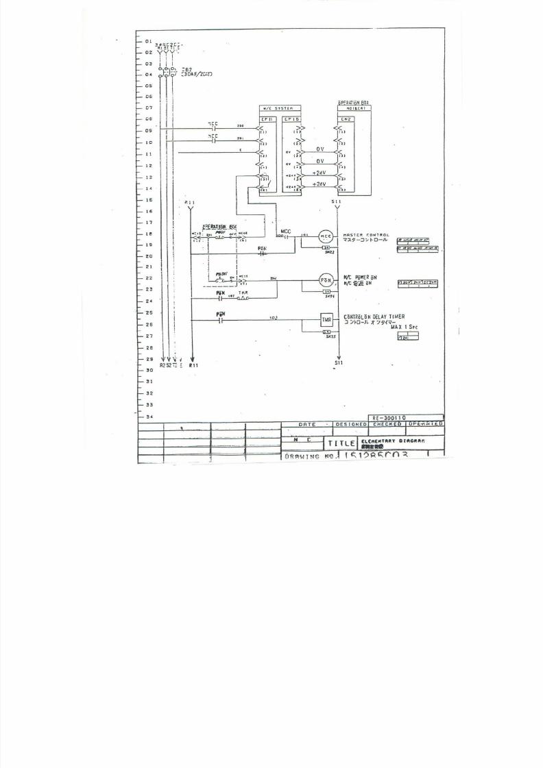
7/21/2019 MORISEIKI MAINTENANCE CLASS
http://slidepdf.com/reader/full/moriseiki-maintenance-class 315/409
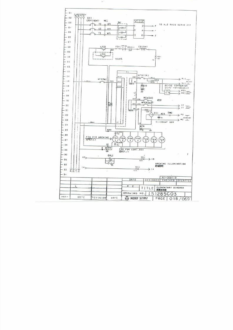
7/21/2019 MORISEIKI MAINTENANCE CLASS
http://slidepdf.com/reader/full/moriseiki-maintenance-class 316/409

7/21/2019 MORISEIKI MAINTENANCE CLASS
http://slidepdf.com/reader/full/moriseiki-maintenance-class 317/409
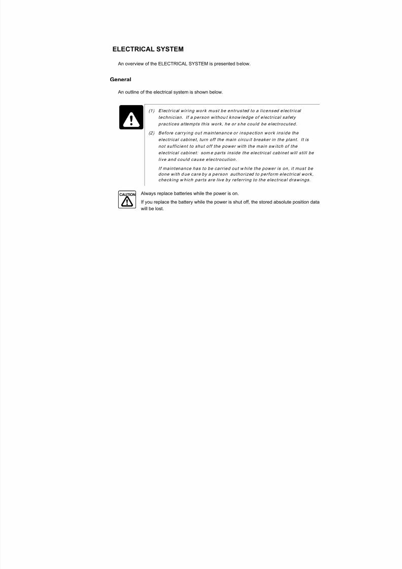
7/21/2019 MORISEIKI MAINTENANCE CLASS
http://slidepdf.com/reader/full/moriseiki-maintenance-class 318/409
ELECTRICAL SYSTEM
An overview of the ELECTRICAL SYSTEM is presented below.
General
An outline of the electrical system is shown below.
Always replace batteries while the power is on.
If you replace the battery while the power is shut off, the stored absolute position data
will be lost.
DANGER (1 ) E lec t r ical wi r ing work must be ent rus ted to a l icensed e lec t r ical
technic ian. I f a person withou t know ledge of electr ical safety
pract ices at tempts this work, he or s he could be electrocuted.
(2 ) Before car ry ing out main tenance or inspection work ins ide the
electr ical cabinet, turn off the main circu it breaker in the plant. It isnot suf f ic ient to shut of f the power with the main sw itch of the
electr ical cabinet: som e parts inside the electr ical cabinet wil l st i l l be
l ive and could cause electrocut ion.
I f maintenance has to be carr ied out w hi le the power is on, i t must be
done with d ue care by a person author ized to perform electr ical work,
checking w hich parts are l ive by referr ing to the electr ical drawings.
CAUTION
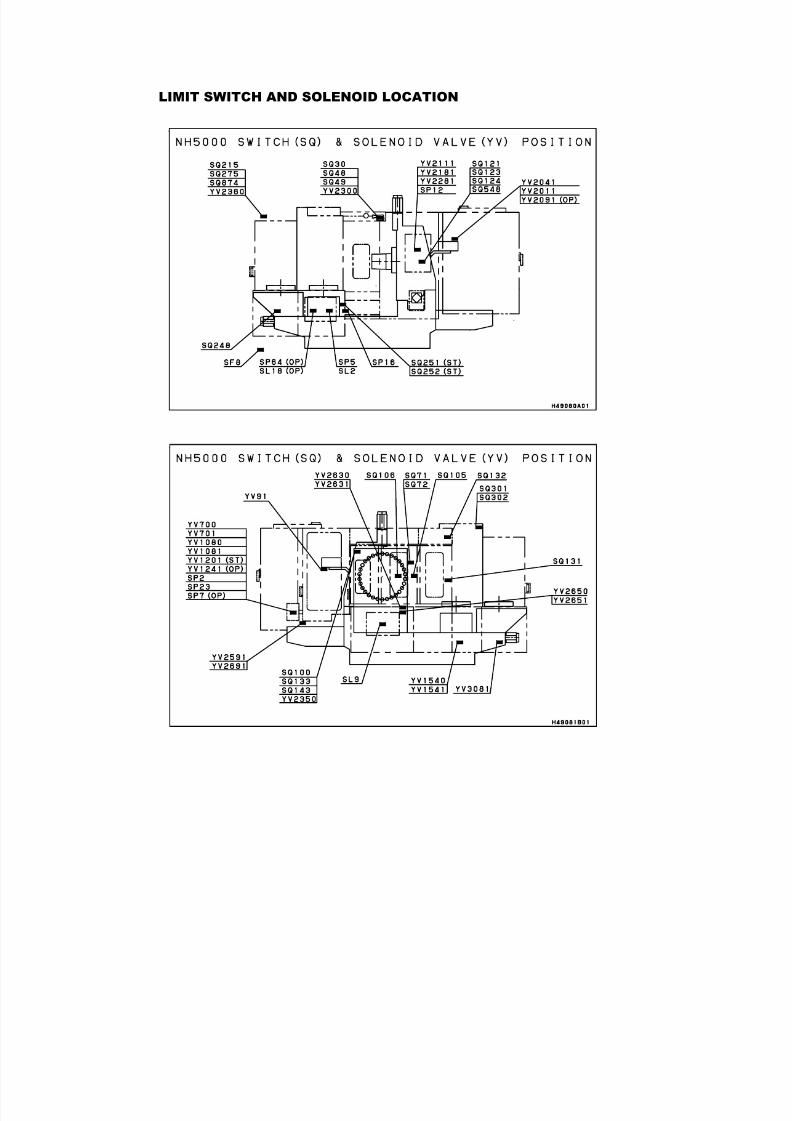
7/21/2019 MORISEIKI MAINTENANCE CLASS
http://slidepdf.com/reader/full/moriseiki-maintenance-class 319/409
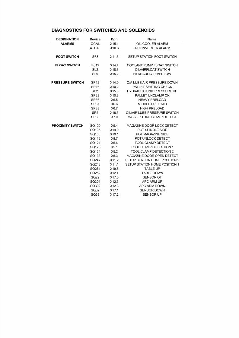
7/21/2019 MORISEIKI MAINTENANCE CLASS
http://slidepdf.com/reader/full/moriseiki-maintenance-class 320/409
DIAGNOSTICS FOR SWITCHES AND SOLENOIDS
DESIGNATION Device Dgn Name
ALARMS OCAL X15.1 OIL COOLER ALARM ATCAL X10.6 ATC INVERTER ALARM
FOOT SWITCH SF8 X11.3 SETUP STATION FOOT SWITCH
FLOAT SWITCH SL12 X14.4 COOLANT PUMP FLOAT SWITCHSL2 X18.3 OIL/AIRFLOAT SWITCHSL9 X15.2 HYDRAULIC LEVEL LOW
PRESSURE SWITCH SP12 X14.0 O/A LUBE AIR PRESSURE DOWNSP16 X10.2 PALLET SEATING CHECKSP2 X15.3 HYDRAULIC UNIT PRESSURE UPSP23 X10.3 PALLET UNCLAMP OKSP36 X6.5 HEAVY PRELOADSP37 X6.6 MIDDLE PRELOADSP38 X6.7 HIGH PRELOADSP5 X18.3 OIL/AIR LUBE PRESSURE SWITCHSP98 X7.0 WSS FIXTURE CLAMP DETECT
PROXIMITY SWITCH SQ100 X5.4 MAGAZINE DOOR LOCK DETECTSQ105 X19.0 POT SPINDLE SIDESQ106 X19.1 POT MAGAZINE SIDESQ112 X8.7 POT UNLOCK DETECTSQ121 X5.6 TOOL CLAMP DETECTSQ123 X5.1 TOOL CLAMP DETECTION 1SQ124 X5.2 TOOL CLAMP DETECTION 2SQ133 X5.3 MAGAZINE DOOR OPEN DETECTSQ247 X11.2 SETUP STATION HOME POSITION 2SQ248 X11.1 SETUP STATION HOME POSITION 1
SQ251 X19.5 TABLE UPSQ252 X12.4 TABLE DOWNSQ29 X17.0 SENSOR OTSQ301 X12.3 APC ARM UPSQ302 X12.3 APC ARM DOWNSQ32 X17.1 SENSOR DOWNSQ33 X17.2 SENSOR UP
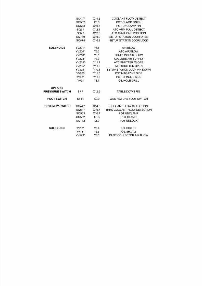
7/21/2019 MORISEIKI MAINTENANCE CLASS
http://slidepdf.com/reader/full/moriseiki-maintenance-class 321/409
SQ447 X14.5 COOLANT FLOW DETECTSQ562 X8.3 POT CLAMP FINISHSQ563 X10.7 POT UNCLAMP FINSQ71 X12.1 ATC ARM PULL DETECTSQ72 X12.0 ATC ARM HOME POSITIONSQ730 X10.0 SETUP STATION DOOR OPENSQ875 X10.1 SETUP STATION DOOR LOCK
SOLENOIDS YV2011 Y6.6 AIR BLOWYV2041 Y6.0 ATC AIR BLOWYV2181 Y8.1 COUPLING AIR BLOWYV2281 Y7.0 O/A LUBE AIR SUPPLYYV2650 Y11.1 ATC SHUTTER CLOSEYV2651 Y11.0 ATC SHUTTER OPEN
YV3081 Y10.4 SETUP STATION LOCK PIN DOWNYV680 Y11.6 POT MAGAZINE SIDEYV681 Y11.5 POT SPINDLE SIDEYV91 Y8.7 OIL HOLE DRILL
OPTIONS
PRESSURE SWITCH SP7 X12.5 TABLE DOWN FIN
FOOT SWITCH SF14 X9.0 WSS FIXTURE FOOT SWITCH
PROXIMITY SWITCH SQ447 X14.5 COOLANT FLOW DETECTIONSQ547 X16.7 THRU COOLANT FLOW DETECTIONSQ563 X10.7 POT UNCLAMPSQ562 X8.3 POT CLAMPSQ112 X8.7 POT UNLOCK
SOLENOIDS YV131 Y6.4 OIL SHOT 1YV141 Y6.5 OIL SHOT 2YV5231 Y8.5 DUST COLLECTOR AIR BLOW
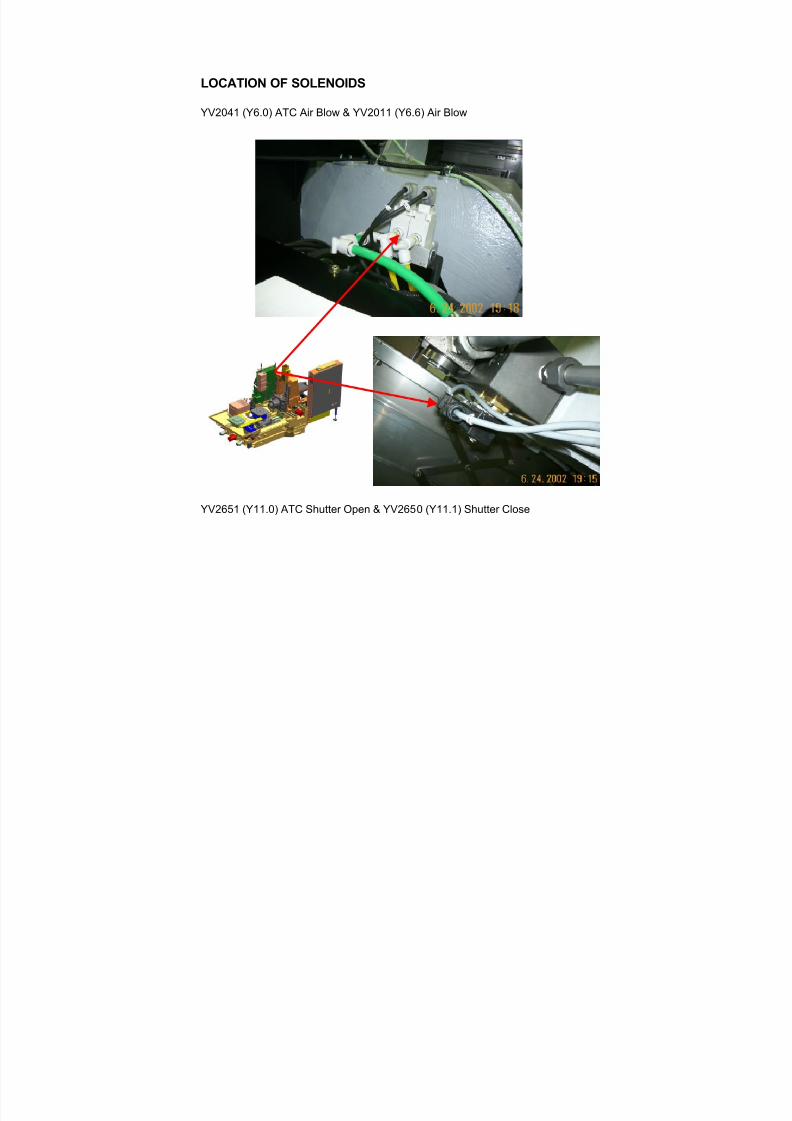
7/21/2019 MORISEIKI MAINTENANCE CLASS
http://slidepdf.com/reader/full/moriseiki-maintenance-class 322/409
LOCATION OF SOLENOIDS
YV2041 (Y6.0) ATC Air Blow & YV2011 (Y6.6) Air Blow
YV2651 (Y11.0) ATC Shutter Open & YV2650 (Y11.1) Shutter Close
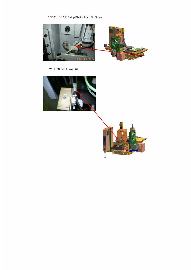
7/21/2019 MORISEIKI MAINTENANCE CLASS
http://slidepdf.com/reader/full/moriseiki-maintenance-class 323/409
YV3081 (Y10.4) Setup Station Lock Pin Down
YV91 (Y8.7) Oil Hole Drill
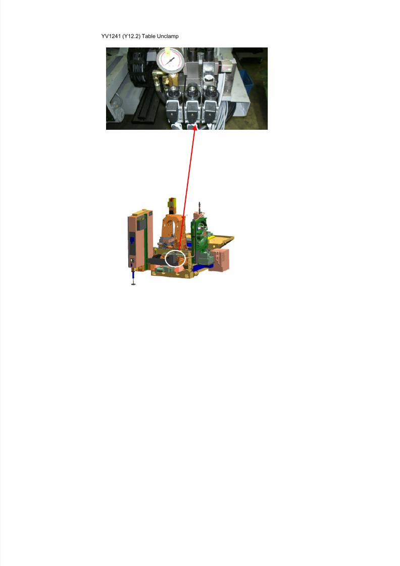
7/21/2019 MORISEIKI MAINTENANCE CLASS
http://slidepdf.com/reader/full/moriseiki-maintenance-class 324/409
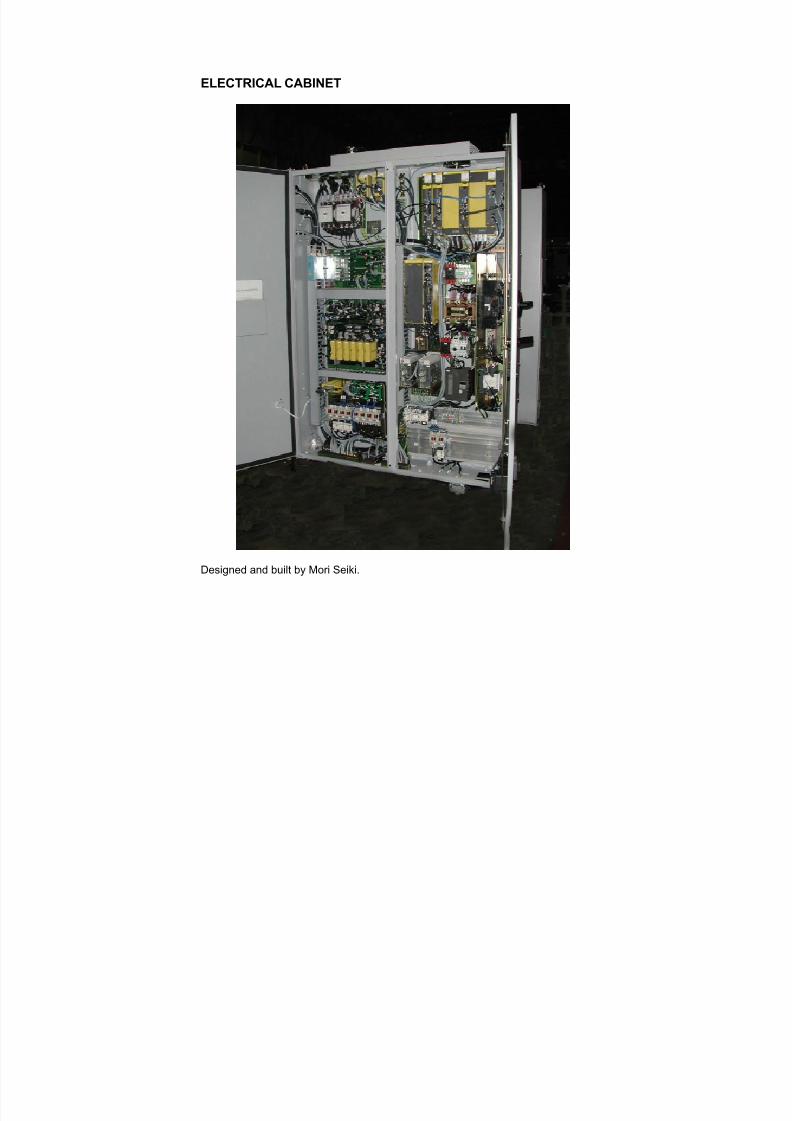
7/21/2019 MORISEIKI MAINTENANCE CLASS
http://slidepdf.com/reader/full/moriseiki-maintenance-class 325/409
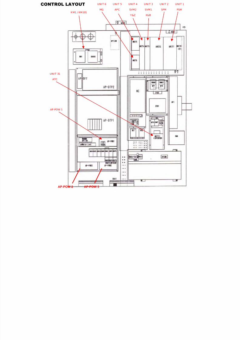
7/21/2019 MORISEIKI MAINTENANCE CLASS
http://slidepdf.com/reader/full/moriseiki-maintenance-class 326/409
UNIT 3
SVM1
X&B
UNIT 1
PSM
UNIT 2
SPM
UNIT 4
SVM2
Y&Z
UNIT 5
APC
UNIT 6
MGKM1 / KM101
AP-POW 1
UNI T 31
ATC
CONTROL LAYOUT
AP-POW 2 AP-POW 3
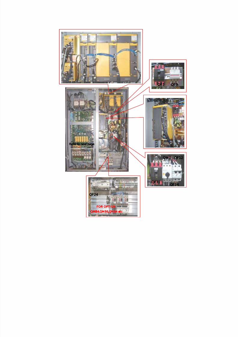
7/21/2019 MORISEIKI MAINTENANCE CLASS
http://slidepdf.com/reader/full/moriseiki-maintenance-class 327/409
QF7QF7QF7QF7 QF9QF9QF9QF9
QM7QM7QM7QM7
QF31QF31QF31QF31QF14QF14QF14QF14
QF12QF12QF12QF12
FOR OPTIONFOR OPTIONFOR OPTIONFOR OPTION
QM84QM84QM84QM84,QM86,QM94 etc,QM86,QM94 etc,QM86,QM94 etc,QM86,QM94 etc
QF24QF24QF24QF24
Refer to next pageRefer to next pageRefer to next pageRefer to next page
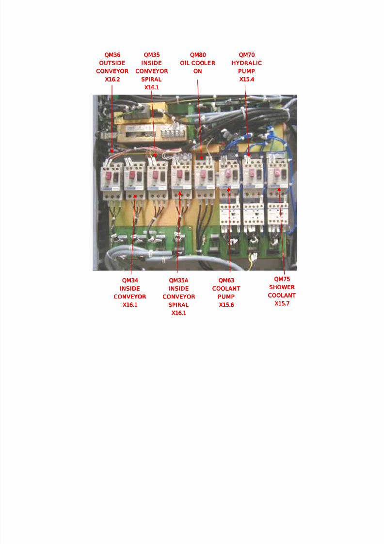
7/21/2019 MORISEIKI MAINTENANCE CLASS
http://slidepdf.com/reader/full/moriseiki-maintenance-class 328/409
QM75QM75QM75QM75
SHOWERSHOWERSHOWERSHOWER
COOLANTCOOLANTCOOLANTCOOLANT
X15.7X15.7X15.7X15.7
QM70QM70QM70QM70
HYDRALICHYDRALICHYDRALICHYDRALIC
PUMPPUMPPUMPPUMP
X15.4X15.4X15.4X15.4
QM63QM63QM63QM63
COOLANTCOOLANTCOOLANTCOOLANT
PUMPPUMPPUMPPUMP
X15.6X15.6X15.6X15.6
QM80QM80QM80QM80
OIL COOLEROIL COOLEROIL COOLEROIL COOLER
ONONONON
QM35AQM35AQM35AQM35A
INSIDEINSIDEINSIDEINSIDE
CONVEYORCONVEYORCONVEYORCONVEYOR
SPIRALSPIRALSPIRALSPIRAL
X16.1X16.1X16.1X16.1
QM35QM35QM35QM35
INSIDEINSIDEINSIDEINSIDE
CONVEYORCONVEYORCONVEYORCONVEYOR
SPIRALSPIRALSPIRALSPIRAL
X16.1X16.1X16.1X16.1
QM34QM34QM34QM34
INSIDEINSIDEINSIDEINSIDE
CONVEYORCONVEYORCONVEYORCONVEYOR
X16.1X16.1X16.1X16.1
QM36QM36QM36QM36
OUTSIDEOUTSIDEOUTSIDEOUTSIDE
CONVEYORCONVEYORCONVEYORCONVEYOR
X16.2X16.2X16.2X16.2
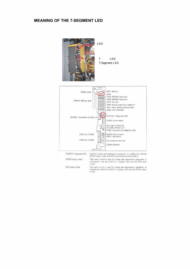
7/21/2019 MORISEIKI MAINTENANCE CLASS
http://slidepdf.com/reader/full/moriseiki-maintenance-class 329/409
LED
7 LED
7-Segment LED
MEANING OF THE 7-SEGMENT LED
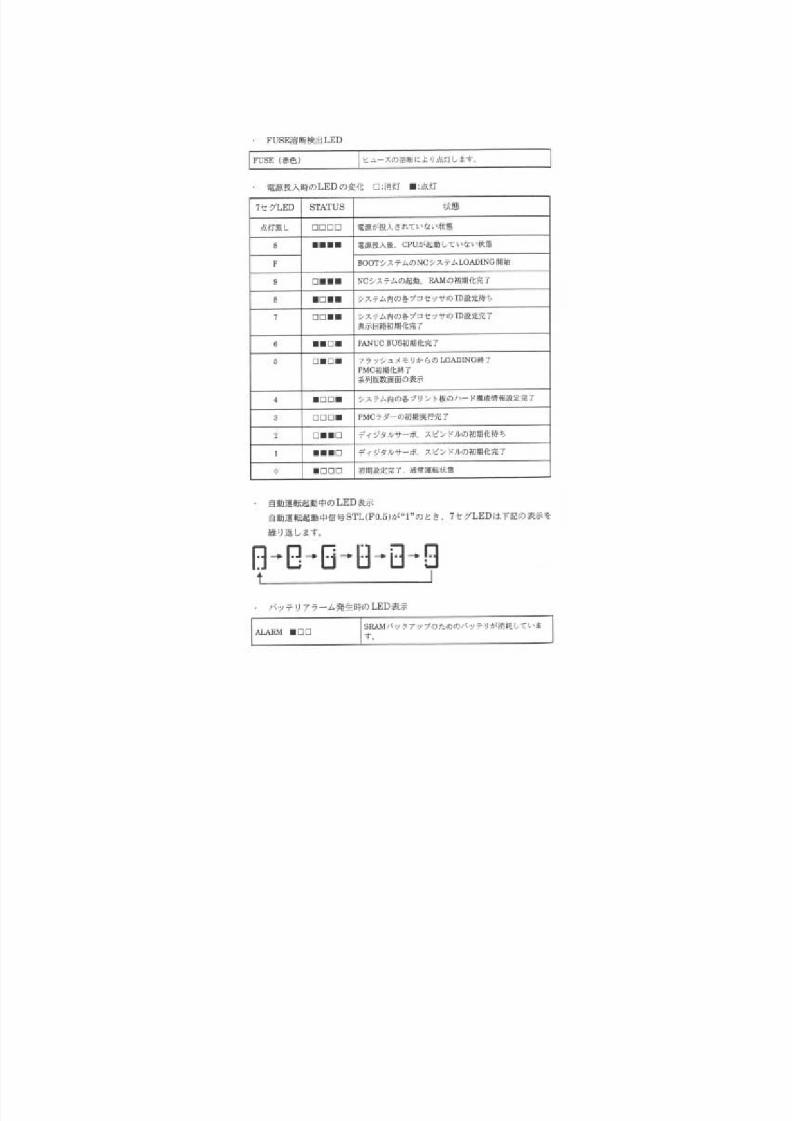
7/21/2019 MORISEIKI MAINTENANCE CLASS
http://slidepdf.com/reader/full/moriseiki-maintenance-class 330/409
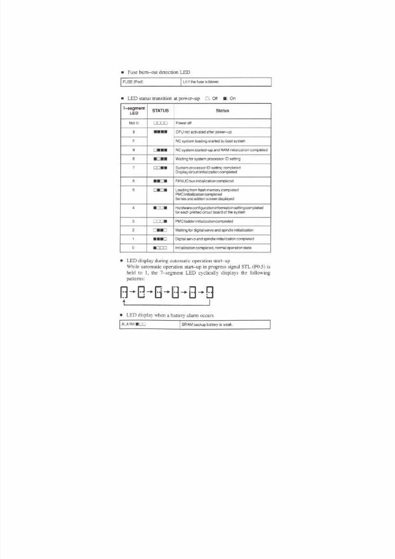
7/21/2019 MORISEIKI MAINTENANCE CLASS
http://slidepdf.com/reader/full/moriseiki-maintenance-class 331/409
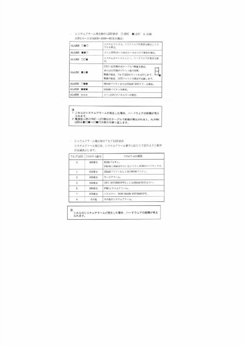
7/21/2019 MORISEIKI MAINTENANCE CLASS
http://slidepdf.com/reader/full/moriseiki-maintenance-class 332/409
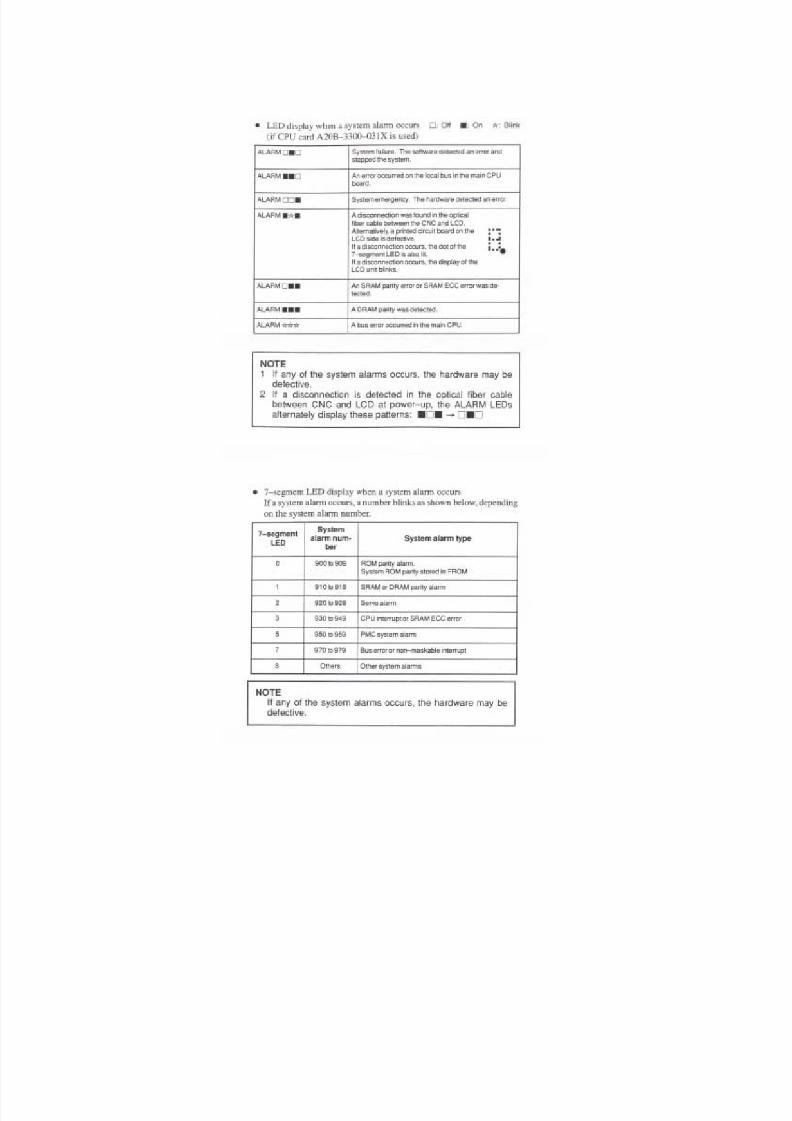
7/21/2019 MORISEIKI MAINTENANCE CLASS
http://slidepdf.com/reader/full/moriseiki-maintenance-class 333/409
7/21/2019 MORISEIKI MAINTENANCE CLASS
http://slidepdf.com/reader/full/moriseiki-maintenance-class 334/409
7/21/2019 MORISEIKI MAINTENANCE CLASS
http://slidepdf.com/reader/full/moriseiki-maintenance-class 335/409

7/21/2019 MORISEIKI MAINTENANCE CLASS
http://slidepdf.com/reader/full/moriseiki-maintenance-class 336/409
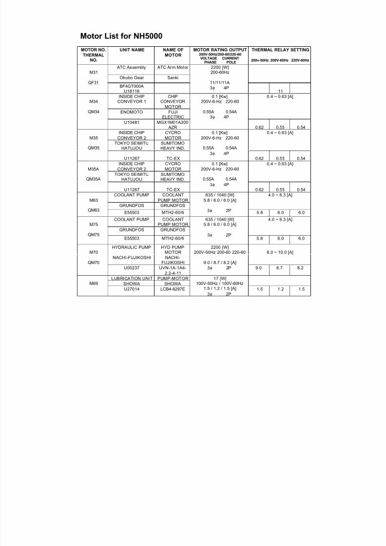
7/21/2019 MORISEIKI MAINTENANCE CLASS
http://slidepdf.com/reader/full/moriseiki-maintenance-class 337/409
Motor List for NH5000
MOTOR NO.
THERMALNO.
UNIT NAME NAME OF
MOTOR
MOTOR RATING OUTPUT200V-50Hz/200-60/220-60VOLTAGE CURRENT
PHASE POLE
THERMAL RELAY SETTING
200v-50Hz 200V-60Hz 220V-60Hz
ATC Assembly ATC Arm Motor
Okubo Gear SankiM31
QF31BF4GT000A
U18116
2200 [W]200-60Hz
11/11/11A3φ 4P
11INSIDE CHIP
CONVEYOR 1CHIP
CONVEYORMOTOR
ENOMOTO FUJIELECTRIC
0.4 ~ 0.63 [A]M34
QM34
U10481 MGX1M01A200 AZR
0.1 [Kw]200V-6-Hz 220-60
0.55A 0.54A3φ 4P
0.62 0.55 0.54
INSIDE CHIPCONVEYOR 2 CYCROMOTORTOKYO SEIMITU
HATUJOUSUMITOMOHEAVY IND.
0.4 ~ 0.63 [A]M35
QM35
U11267 TC-EX
0.1 [Kw]200V-6-Hz 220-60
0.55A 0.54A3φ 4P
0.62 0.55 0.54INSIDE CHIP
CONVEYOR 2CYCROMOTOR
TOKYO SEIMITUHATUJOU
SUMITOMOHEAVY IND.
0.4 ~ 0.63 [A]M35A
QM35A
U11267 TC-EX
0.1 [Kw]200V-6-Hz 220-60
0.55A 0.54A3φ 4P
0.62 0.55 0.54COOLANT PUMP COOLANT
PUMP MOTORGRUNDFOS GRUNDFOS
4.0 ~ 6.3 [A]
M63QM63
E55503 MTH2-60/6
635 / 1040 [W]
5.8 / 6.0 / 6.0 [A]
3φ 2P 5.8 6.0 6.0
COOLANT PUMP COOLANTPUMP MOTOR
GRUNDFOS GRUNDFOS
4.0 ~ 6.3 [A]M75
QM75E55503 MTH2-60/6
635 / 1040 [W]5.8 / 6.0 / 6.0 [A]
3φ 2P5.8 6.0 6.0
HYDRAULIC PUMP HYD PUMPMOTOR
NACHI-FUJIKOSHI NACHI-FUJIKOSHI
6.0 ~ 10.0 [A]M70
QM70
U00237 UVN-1A-1A4-2.2-4-11
2200 [W]200V-50Hz 200-60 220-60
9.0 / 8.7 / 8.2 [A]
3φ 2P 9.0 8.7 8.2
LUBRICATION UNIT PUMP-MOTORSHOWA SHOWAM69U27014 LCB4-8297E
17 [W]100V-50Hz / 100V-60Hz
1.5 / 1.2 / 1.5 [A]3φ 2P
1.5 1.2 1.5
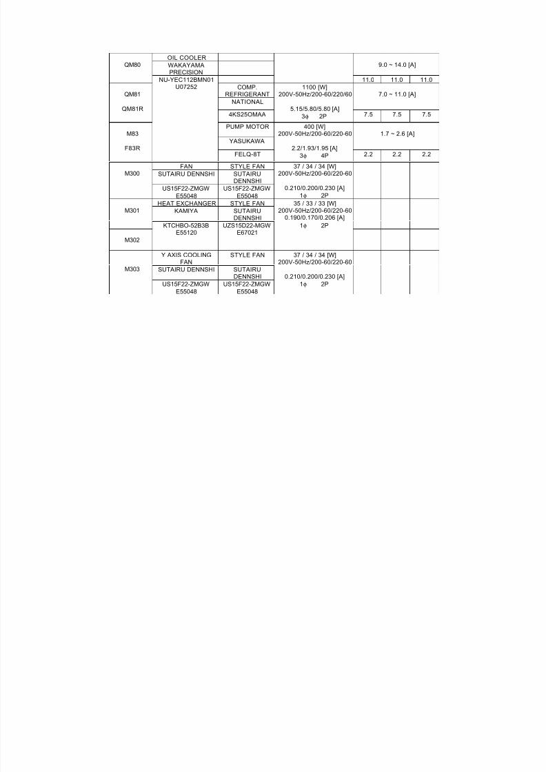
7/21/2019 MORISEIKI MAINTENANCE CLASS
http://slidepdf.com/reader/full/moriseiki-maintenance-class 338/409
OIL COOLERWAKAYAMAPRECISION
9.0 ~ 14.0 [A]QM80
11.0 11.0 11.0COMP.
REFRIGERANTNATIONAL
7.0 ~ 11.0 [A]QM81
QM81R4KS25OMAA
1100 [W]
200V-50Hz/200-60/220/60
5.15/5.80/5.80 [A]3φ 2P 7.5 7.5 7.5
PUMP MOTOR
YASUKAWA1.7 ~ 2.6 [A]M83
F83R
NU-YEC112BMN01U07252
FELQ-8T
400 [W]200V-50Hz/200-60/220-60
2.2/1.93/1.95 [A]3φ 4P 2.2 2.2 2.2
FAN STYLE FANSUTAIRU DENNSHI SUTAIRU
DENNSHIM300
US15F22-ZMGWE55048 US15F22-ZMGWE55048
37 / 34 / 34 [W]200V-50Hz/200-60/220-60
0.210/0.200/0.230 [A]1φ 2PHEAT EXCHANGER STYLE FAN
KAMIYA SUTAIRUDENNSHI
M301
M302
KTCHBO-52B3BE55120
UZS15D22-MGWE67021
35 / 33 / 33 [W]200V-50Hz/200-60/220-60
0.190/0.170/0.206 [A]1φ 2P
Y AXIS COOLINGFAN
STYLE FAN
SUTAIRU DENNSHI SUTAIRUDENNSHI
M303
US15F22-ZMGWE55048 US15F22-ZMGWE55048
37 / 34 / 34 [W]200V-50Hz/200-60/220-60
0.210/0.200/0.230 [A]
1φ 2P
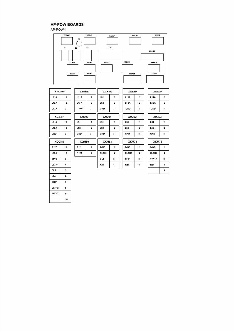
7/21/2019 MORISEIKI MAINTENANCE CLASS
http://slidepdf.com/reader/full/moriseiki-maintenance-class 339/409
AP-POW BOARDS
AP-POW-1
XPOWP
L11A 1
L12A 2
L13A 3
XTRNS
L11A 1
L12A 2
GND 3
XCX1A
L51 1
L52 2
GND 3
XGS1P
L11A 1
L12A 2
GND 3
XGS2P
L11A 1
L12A 2
GND 3
XGS3P
L11A 1
L12A 2
GND 3
XM300
L51 1
L52 2
GND 3
XM301
L51 1
L52 2
GND 3
XM302
L51 1
L52 2
GND 3
XM303
L51 1
L52 2
GND 3
XQM80
R12 1
R12A 2
XKM63
24NC 1
CLTH1 2
CLT 3
XKM73
24NC 1
CLTH2 2
CHIP 3
XKM75
24NC 1
CLTH2 2
SWCLT 3
XCONS
R12B 1
L12A 2
24NC 3
CLTH1 4
CLT 5
N24 6
CHIP 7
CLTH2 8
SWCLT 9
10
N24 4 N24 4 N24 4
5
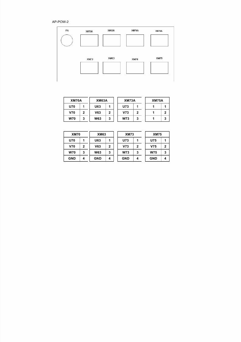
7/21/2019 MORISEIKI MAINTENANCE CLASS
http://slidepdf.com/reader/full/moriseiki-maintenance-class 340/409
AP-POW-2
XM70A
U70 1
V70 2
W70 3
XM70
U70 1
V70 2
W70 3
GND 4
XM63A
U63 1
V63 2
W63 3
XM73A
U73 1
V73 2
W73 3
XM75A
1 1
1 2
1 3
XM63
U63 1
V63 2
W63 3
GND 4
XM73
U73 1
V73 2
W73 3
GND 4
XM75
U75 1
V75 2
W75 3
GND 4
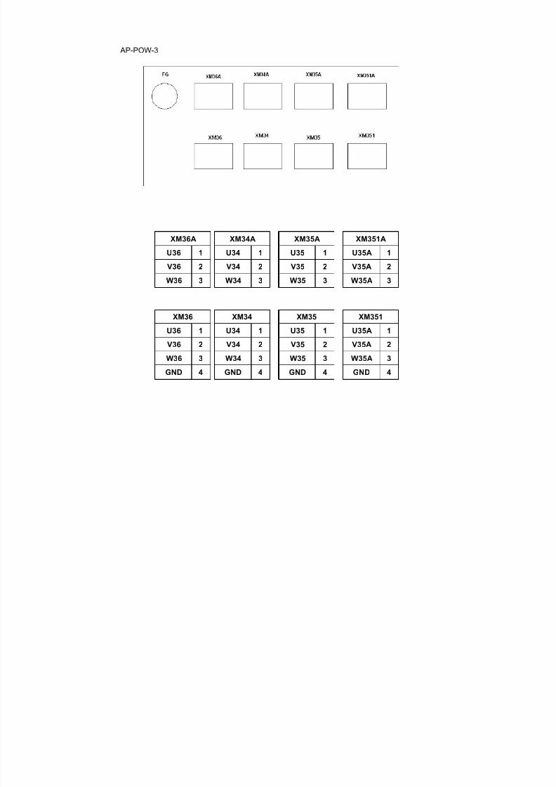
7/21/2019 MORISEIKI MAINTENANCE CLASS
http://slidepdf.com/reader/full/moriseiki-maintenance-class 341/409
AP-POW-3
XM36A
U36 1
V36 2
W36 3
XM36
U36 1
V36 2
W36 3
GND 4
XM34A
U34 1
V34 2
W34 3
XM35A
U35 1
V35 2
W35 3
XM351A
U35A 1
V35A 2
W35A 3
XM34
U34 1
V34 2
W34 3
GND 4
XM35
U35 1
V35 2
W35 3
GND 4
XM351
U35A 1
V35A 2
W35A 3
GND 4
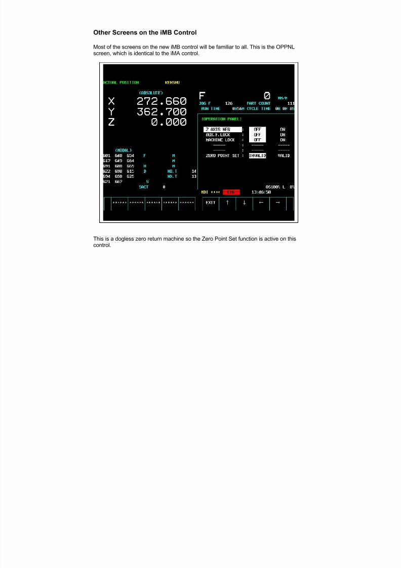
7/21/2019 MORISEIKI MAINTENANCE CLASS
http://slidepdf.com/reader/full/moriseiki-maintenance-class 342/409
Other Screens on the iMB Control
Most of the screens on the new iMB control will be familiar to all. This is the OPPNLscreen, which is identical to the iMA control.
This is a dogless zero return machine so the Zero Point Set function is active on thiscontrol.
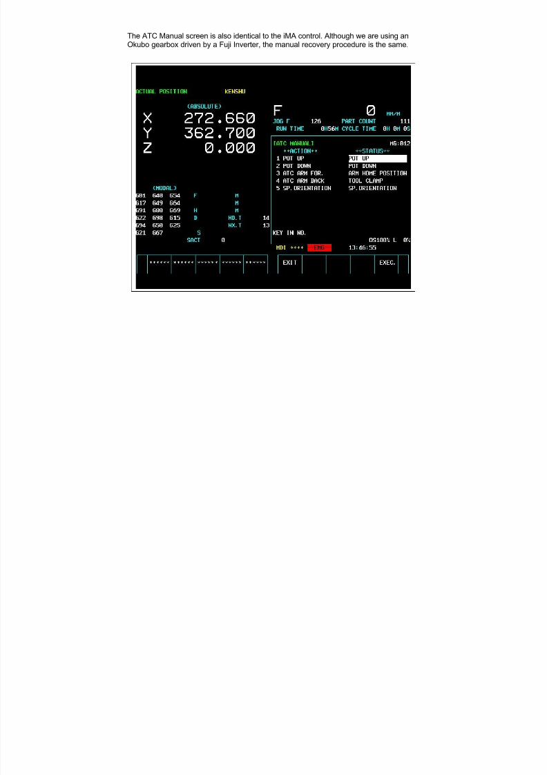
7/21/2019 MORISEIKI MAINTENANCE CLASS
http://slidepdf.com/reader/full/moriseiki-maintenance-class 343/409
The ATC Manual screen is also identical to the iMA control. Although we are using anOkubo gearbox driven by a Fuji Inverter, the manual recovery procedure is the same.
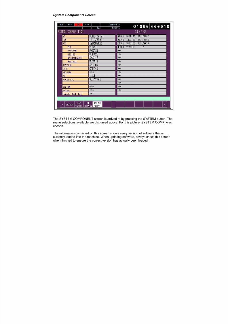
7/21/2019 MORISEIKI MAINTENANCE CLASS
http://slidepdf.com/reader/full/moriseiki-maintenance-class 344/409
System Components Screen
The SYSTEM COMPONENT screen is arrived at by pressing the SYSTEM button. Themenu selections available are displayed above. For this picture, SYSTEM COMP. waschosen.
The information contained on this screen shows every version of software that iscurrently loaded into the machine. When updating software, always check this screenwhen finished to ensure the correct version has actually been loaded.
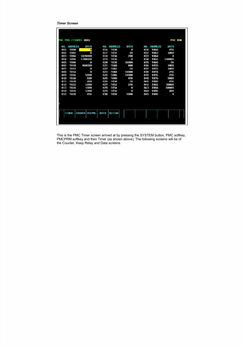
7/21/2019 MORISEIKI MAINTENANCE CLASS
http://slidepdf.com/reader/full/moriseiki-maintenance-class 345/409
Timer Screen
This is the PMC Timer screen arrived at by pressing the SYSTEM button, PMC softkey,PMCPRM softkey and then Timer (as shown above). The following screens will be of the Counter, Keep Relay and Data screens.

7/21/2019 MORISEIKI MAINTENANCE CLASS
http://slidepdf.com/reader/full/moriseiki-maintenance-class 346/409
Counter Screen
Keep Relay Screen
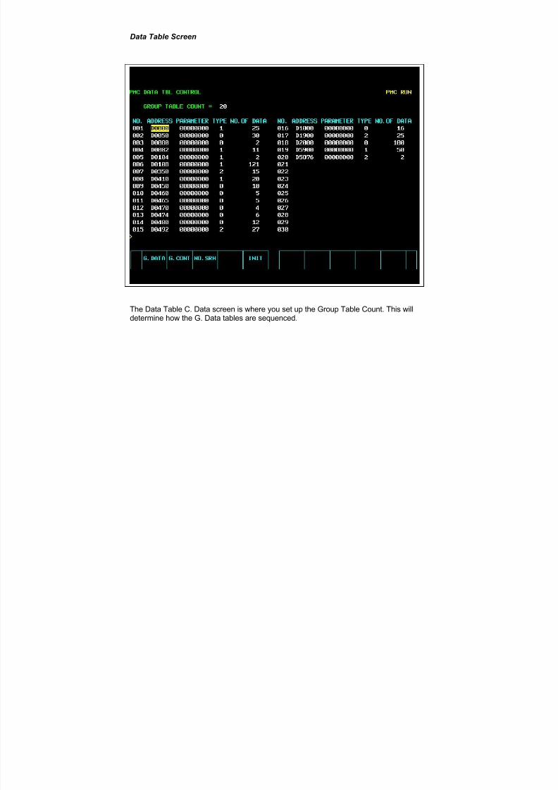
7/21/2019 MORISEIKI MAINTENANCE CLASS
http://slidepdf.com/reader/full/moriseiki-maintenance-class 347/409
Data Table Screen
The Data Table C. Data screen is where you set up the Group Table Count. This willdetermine how the G. Data tables are sequenced.
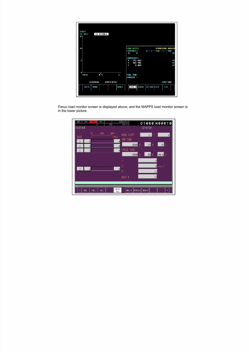
7/21/2019 MORISEIKI MAINTENANCE CLASS
http://slidepdf.com/reader/full/moriseiki-maintenance-class 348/409
Fanuc load monitor screen is displayed above, and the MAPPS load monitor screen isin the lower picture.
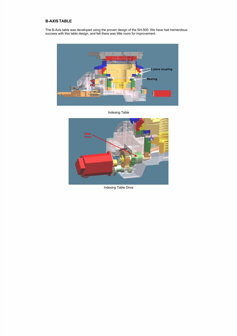
7/21/2019 MORISEIKI MAINTENANCE CLASS
http://slidepdf.com/reader/full/moriseiki-maintenance-class 349/409
B-AXIS TABLE
The B-Axis table was developed using the proven design of the SH-500. We have had tremendoussuccess with this table design, and felt there was little room for improvement.
Indexing Table
Indexing Table Drive
3 piece coupling
Bearing
Gear
Drive

7/21/2019 MORISEIKI MAINTENANCE CLASS
http://slidepdf.com/reader/full/moriseiki-maintenance-class 350/409
Rotary Table
Rotary Table Drive
Worm Wheel
Worm Shaft
ClampingHooksClamping
Piston
Worm Drive using a Belt

7/21/2019 MORISEIKI MAINTENANCE CLASS
http://slidepdf.com/reader/full/moriseiki-maintenance-class 351/409
The B-Axis table will come standard as a 1° indexer with a full fourth axis offered as an option, asshown above.
You can see the three piece coupling on the picture of the indexing table, which is not used on the full4th axis table. The rotary table is using a hydraulic brake, as is normally the case, to hold the table in
position.
You can also see the difference in drive mechanisms between the two different tables. The Indexer uses a gear train mechanism to rotate the table, while the rotary table uses a belt drive attached to aworm shaft.

7/21/2019 MORISEIKI MAINTENANCE CLASS
http://slidepdf.com/reader/full/moriseiki-maintenance-class 352/409
1
6
5
3
9
7
10
11
12
14
16
17 19
8
13
15
18 20
2
4
1 Degree Indexer
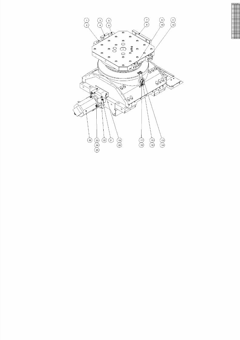
7/21/2019 MORISEIKI MAINTENANCE CLASS
http://slidepdf.com/reader/full/moriseiki-maintenance-class 353/409
1726 23 1922 21 1315
24 20 18 1416
2
1
4
3
8
7
12
11
10
9
6
5
25

7/21/2019 MORISEIKI MAINTENANCE CLASS
http://slidepdf.com/reader/full/moriseiki-maintenance-class 354/409
A
Detail Drawing A
2 3 4 5 6 7 9 108 11 12 13 14 16 1817 19 20 21 22 2423
25
26
27
28
29 30 31 33 3432
664656869 6667
70
7374 72 7175767778798082 818384858687
88899091
94
93
92
95
96
97
99
98
100
1
101
102
103
104
105
15
Apply Greese(ALVANIA EP)グリス塗布(アルバニアEP)
Apply Screw Lock(Three Bond)ネジロック塗布(スリーボンド 1344 )
0 . 5
C l e a r a n c e
m m
ス キ マ
0 . 5 m m
C l e a r a n c e
- 0 . 0
3 m m
ス キ マ
- 0 . 0
3 m m
Apply Grease(ALVANIA EP)グリス塗布(アルバニアEP)
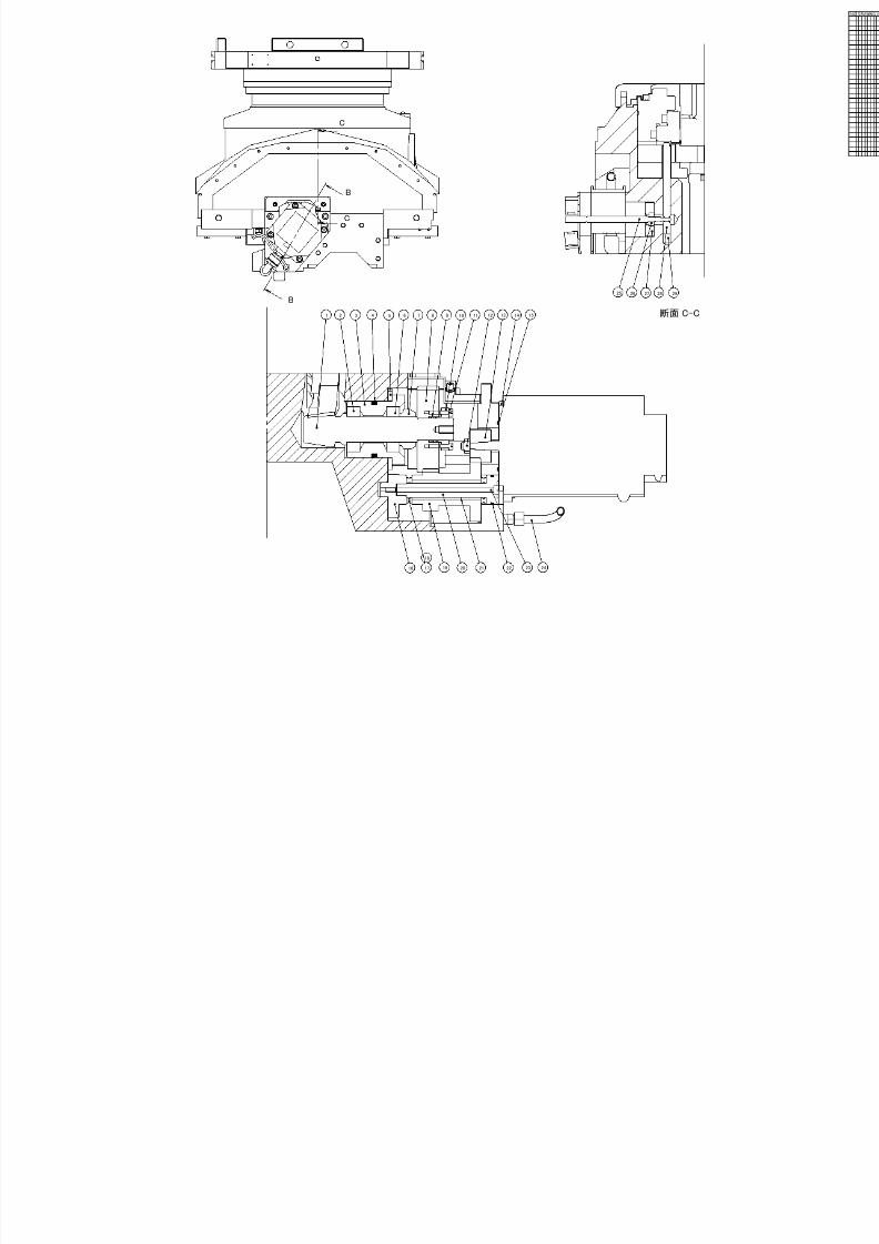
7/21/2019 MORISEIKI MAINTENANCE CLASS
http://slidepdf.com/reader/full/moriseiki-maintenance-class 355/409
断面 C-C1 2 3 5 6 7 8 9 10 11
16 17 19 20 21 23 24
12 13 14 15
22
28272625
4
29
18
B
B
C
C
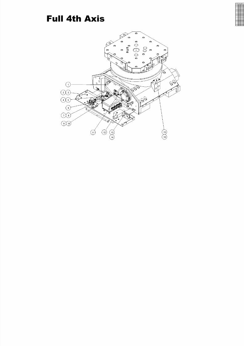
7/21/2019 MORISEIKI MAINTENANCE CLASS
http://slidepdf.com/reader/full/moriseiki-maintenance-class 356/409
3
8
6
1
2
7
54
109
12 13
14
1511
16
Full 4th Axis
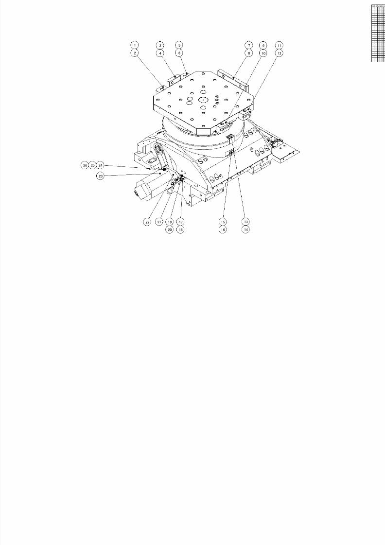
7/21/2019 MORISEIKI MAINTENANCE CLASS
http://slidepdf.com/reader/full/moriseiki-maintenance-class 357/409
23
24
1719 15 13
2 4 6 8 1210
25
2122
20 16 14
1 3 5 7 9 11
18
26
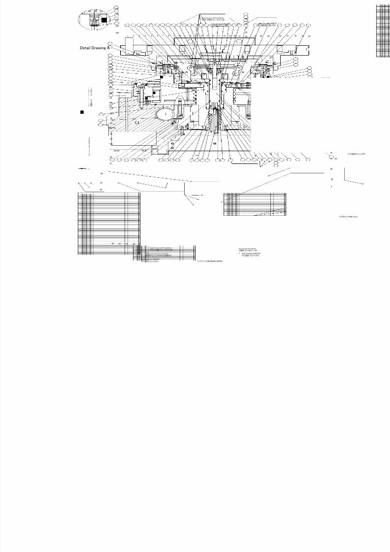
7/21/2019 MORISEIKI MAINTENANCE CLASS
http://slidepdf.com/reader/full/moriseiki-maintenance-class 358/409
A
Detail Drawing A
103
101
100
99
98
97
96
95
94
93
92
91
90
89
8788
86
85
84
83 82 81 80 79 78 77 76 75 74 73 72 71 70 69 68 67 66 65 64 63 61 58
59
60
57 56 55 54
41
40
39
38
37
36
35
343332313029282722
23
24
25
26
2120191817151413 16121110987654321
102
104
62
105
106
107
108
109
Apply Screw Lock(Three Bond)
ネジロック塗布(スリーボンド 1344)
Apply Grease(ALVANIA EP)グリス塗布(アルバニアEP)
Apply Grease(ALVANIA EP)グリス塗布(アルバニアEP)
Apply Grease(ALVANIA EP)グリス塗布(アルバニアEP)
Apply Screw Lock(Three Bond)
ネジロック塗布(スリーボンド 1344)
Apply Grease(ALVANIA EP)グリス塗布(アルバニアEP)
Apply Grease(ALVANIA EP)グリス塗布(アルバニアEP)
Apply Screw Lock(Three Bond)
ネジロック塗布(スリーボンド 1344)
Adjust based accuracy test results chart belong inductosynインダクトシン付属の検査表に基き現合
Apply worm gear oil at assembling組立時 ウォームギヤオイルを塗布する
A p p
l y G r e a s e
( A L V A N I A
E P )
グ リ ス 塗 布 ( ア ル バ ニ ア E P )
S t a r
t i n g
t o r q u e
3 . 9 ~ 4
. 4 N ・ m
起 動 ト ル ク
3 . 9 ~ 4
. 4 N ・ m
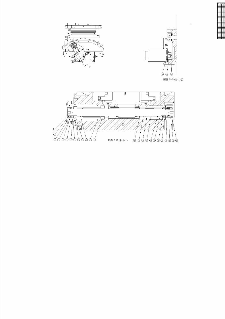
7/21/2019 MORISEIKI MAINTENANCE CLASS
http://slidepdf.com/reader/full/moriseiki-maintenance-class 359/409
C
C
断面 C-C
B
B
断面 B-B
(S=1/2
(S=1/1)3 4 5 6 8
2
1
7 9 10 11 12 13 14 1615 18 19 22 23 2524
27 2826
17 2120
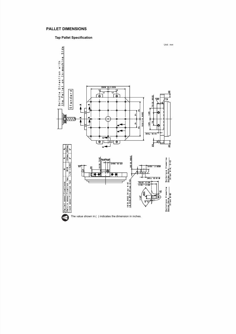
7/21/2019 MORISEIKI MAINTENANCE CLASS
http://slidepdf.com/reader/full/moriseiki-maintenance-class 360/409
PALLET DIMENSIONS
Tap Pallet Specification
Unit: mm
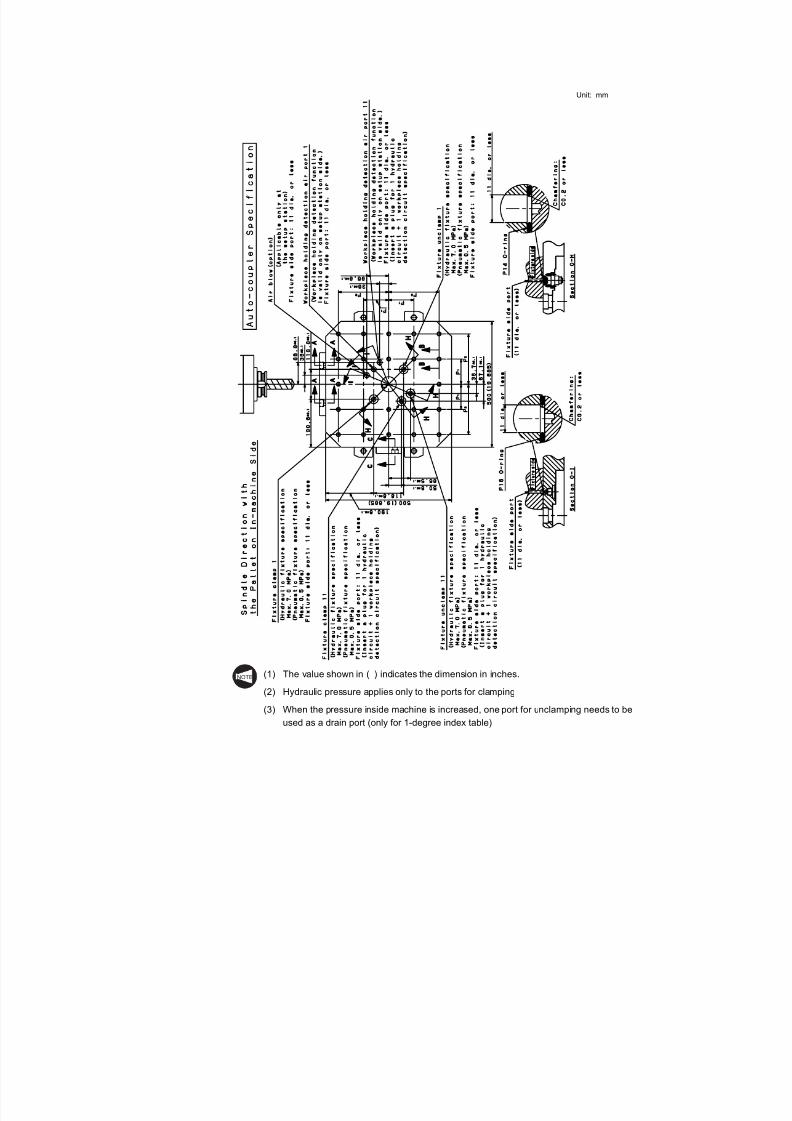
7/21/2019 MORISEIKI MAINTENANCE CLASS
http://slidepdf.com/reader/full/moriseiki-maintenance-class 361/409
Unit: mm
(1) The value shown in ( ) indicates the dimension in inches.
(2) Hydraulic pressure applies only to the ports for clamping(3) When the pressure inside machine is increased, one port for unclamping needs to be
NOTE
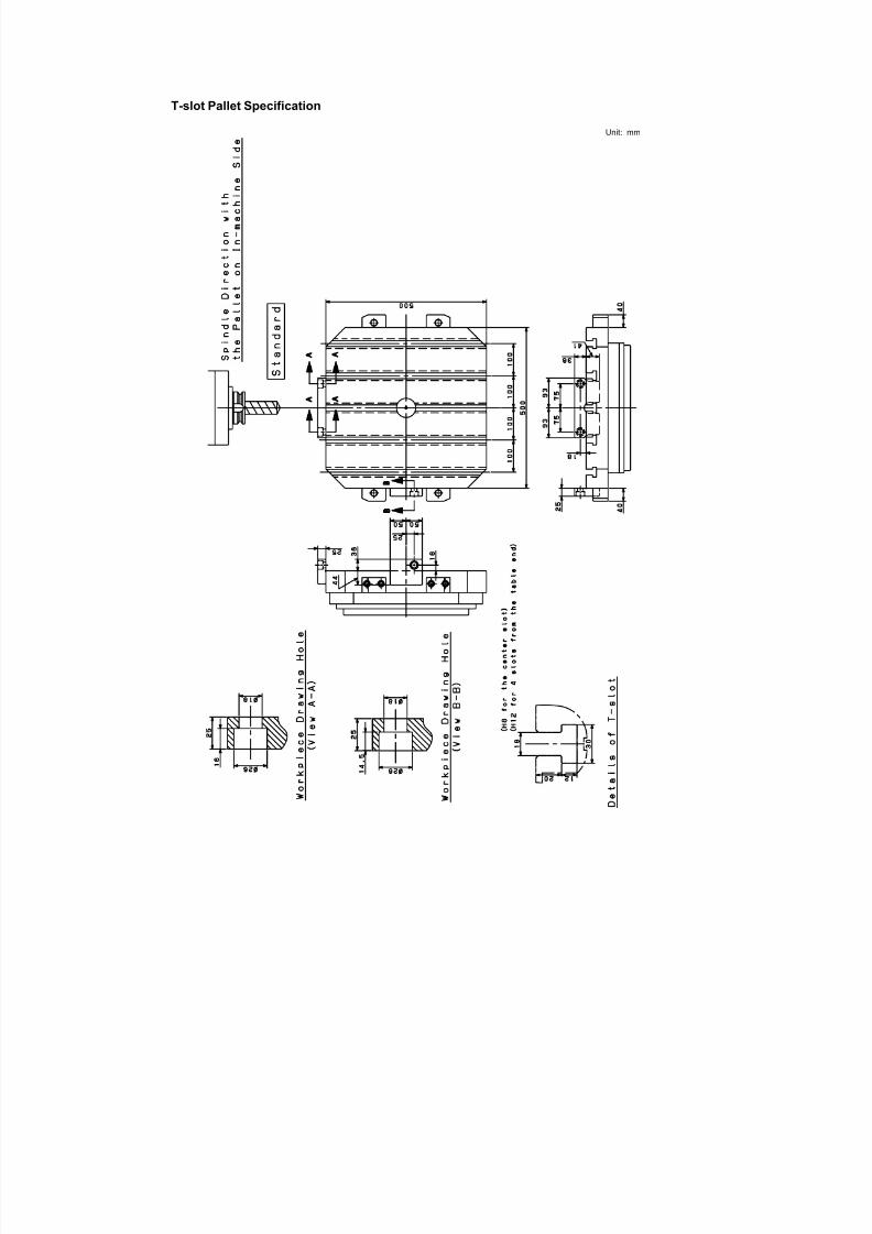
7/21/2019 MORISEIKI MAINTENANCE CLASS
http://slidepdf.com/reader/full/moriseiki-maintenance-class 362/409
T-slot Pallet Specification
Unit: mm

7/21/2019 MORISEIKI MAINTENANCE CLASS
http://slidepdf.com/reader/full/moriseiki-maintenance-class 363/409
Unit: mm
(1) The value shown in ( ) indicates the dimension in inches.
(2) Hydraulic pressure applies only to the ports for clamping(3) When the pressure inside machine is increased, one port for unclamping needs to be
NOTE
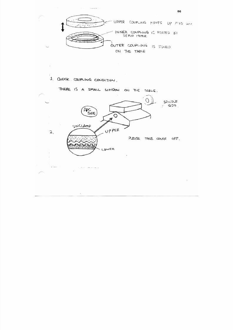
7/21/2019 MORISEIKI MAINTENANCE CLASS
http://slidepdf.com/reader/full/moriseiki-maintenance-class 364/409
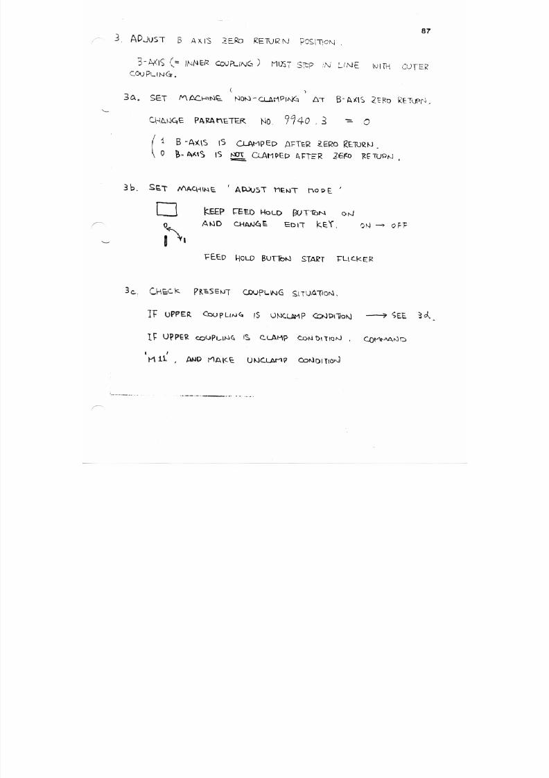
7/21/2019 MORISEIKI MAINTENANCE CLASS
http://slidepdf.com/reader/full/moriseiki-maintenance-class 365/409
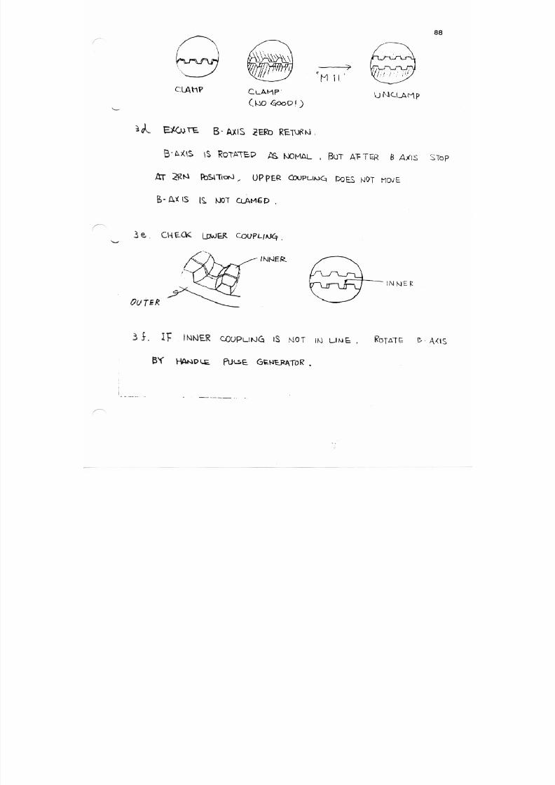
7/21/2019 MORISEIKI MAINTENANCE CLASS
http://slidepdf.com/reader/full/moriseiki-maintenance-class 366/409
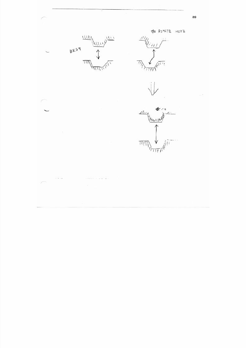
7/21/2019 MORISEIKI MAINTENANCE CLASS
http://slidepdf.com/reader/full/moriseiki-maintenance-class 367/409
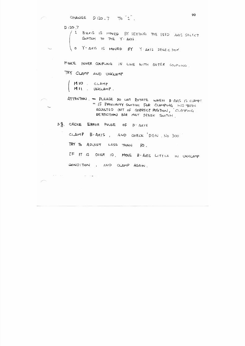
7/21/2019 MORISEIKI MAINTENANCE CLASS
http://slidepdf.com/reader/full/moriseiki-maintenance-class 368/409
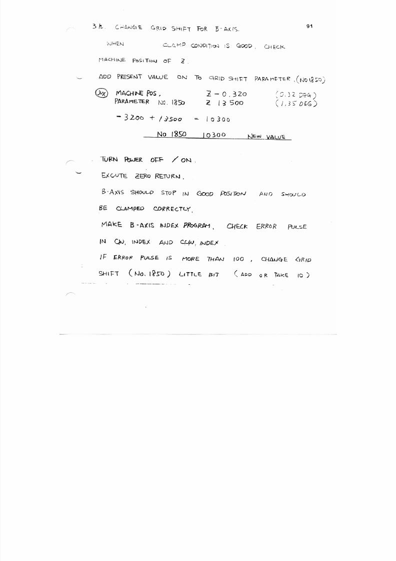
7/21/2019 MORISEIKI MAINTENANCE CLASS
http://slidepdf.com/reader/full/moriseiki-maintenance-class 369/409
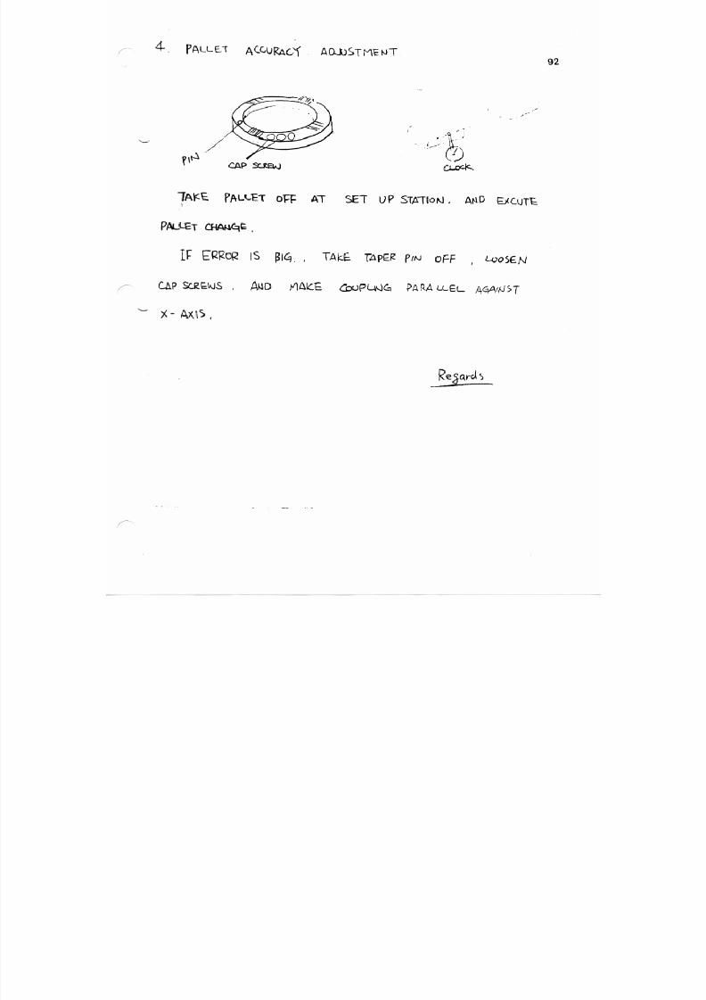
7/21/2019 MORISEIKI MAINTENANCE CLASS
http://slidepdf.com/reader/full/moriseiki-maintenance-class 370/409
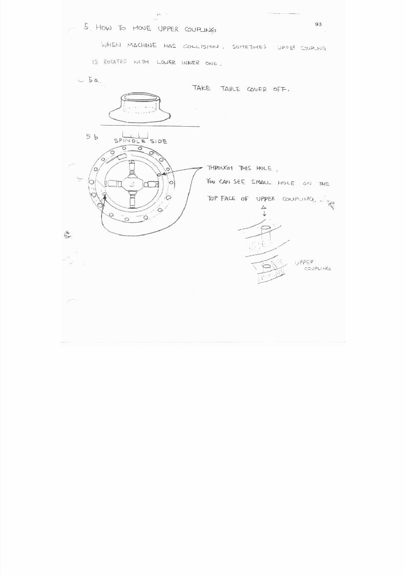
7/21/2019 MORISEIKI MAINTENANCE CLASS
http://slidepdf.com/reader/full/moriseiki-maintenance-class 371/409
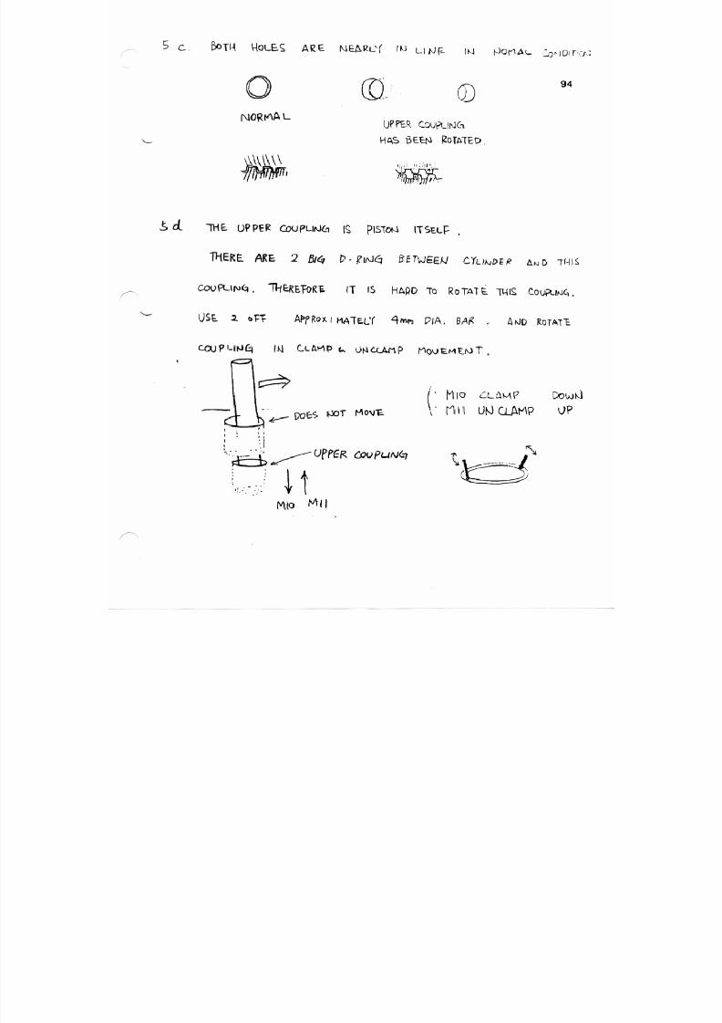
7/21/2019 MORISEIKI MAINTENANCE CLASS
http://slidepdf.com/reader/full/moriseiki-maintenance-class 372/409
7/21/2019 MORISEIKI MAINTENANCE CLASS
http://slidepdf.com/reader/full/moriseiki-maintenance-class 373/409
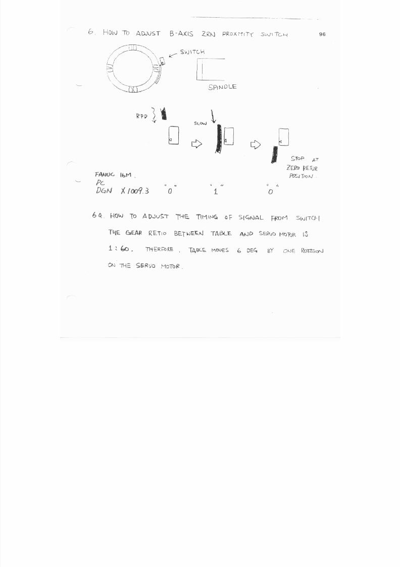
7/21/2019 MORISEIKI MAINTENANCE CLASS
http://slidepdf.com/reader/full/moriseiki-maintenance-class 374/409
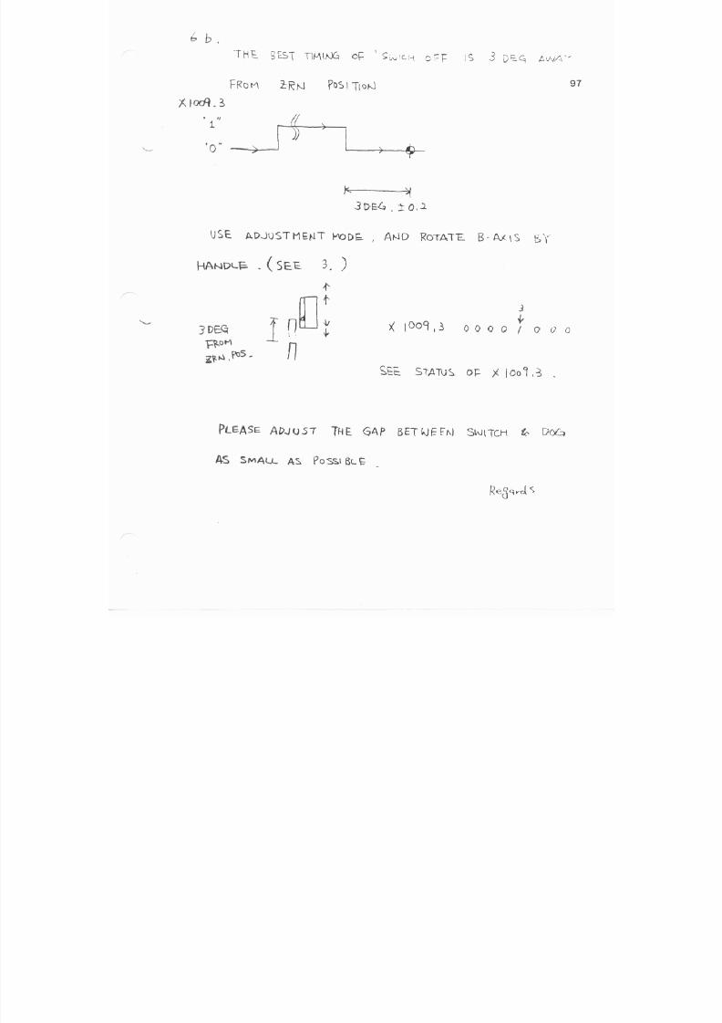
7/21/2019 MORISEIKI MAINTENANCE CLASS
http://slidepdf.com/reader/full/moriseiki-maintenance-class 375/409

7/21/2019 MORISEIKI MAINTENANCE CLASS
http://slidepdf.com/reader/full/moriseiki-maintenance-class 376/409
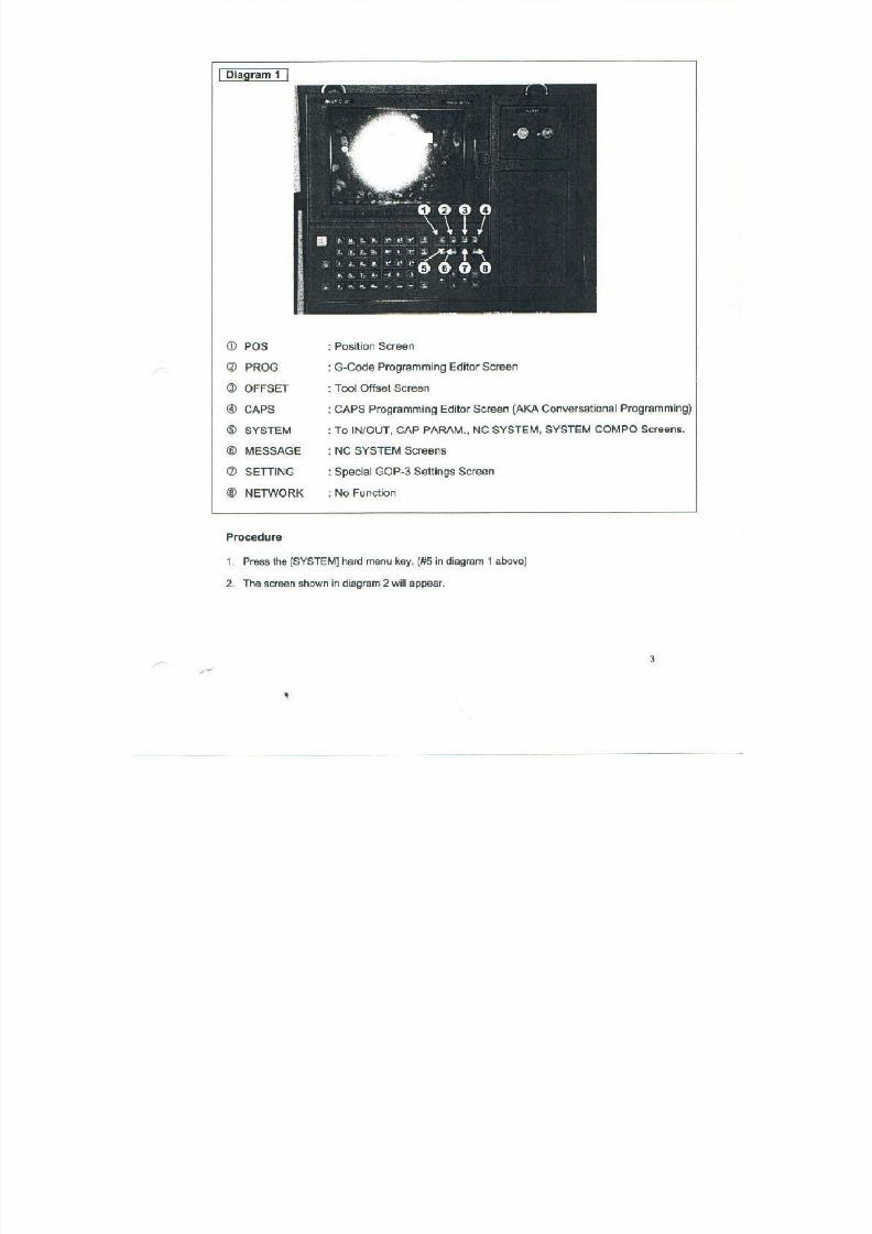
7/21/2019 MORISEIKI MAINTENANCE CLASS
http://slidepdf.com/reader/full/moriseiki-maintenance-class 377/409
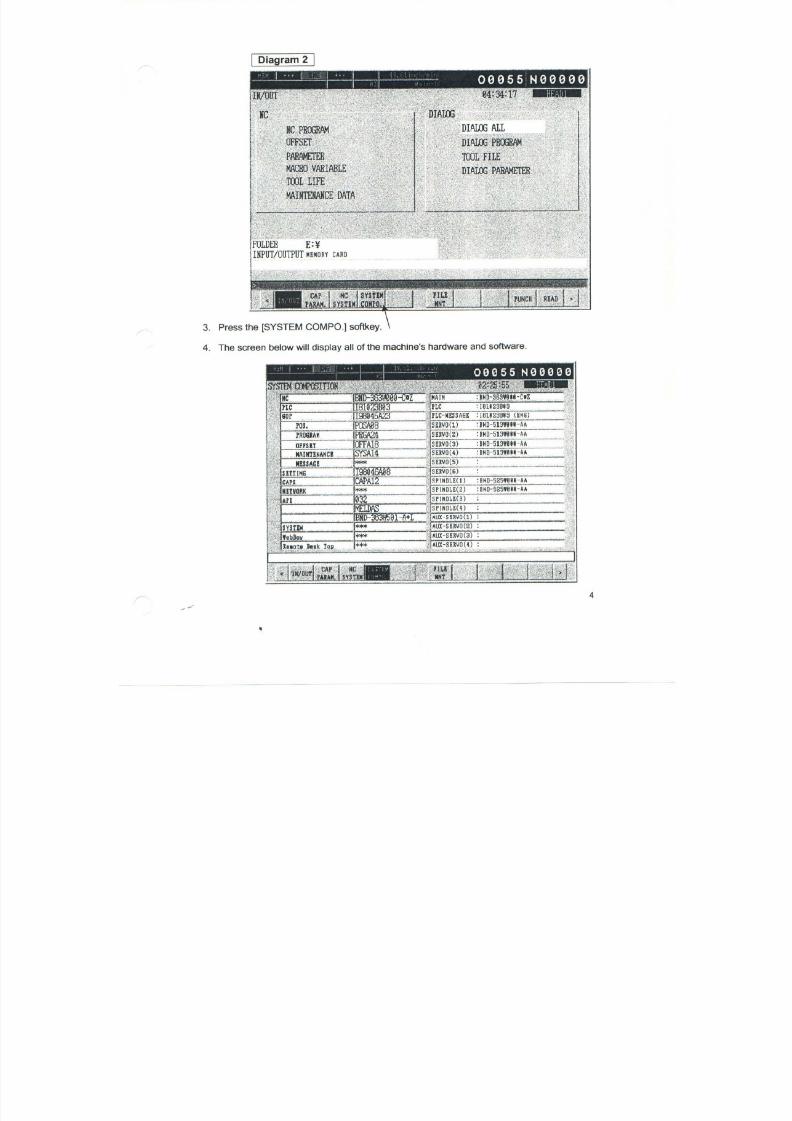
7/21/2019 MORISEIKI MAINTENANCE CLASS
http://slidepdf.com/reader/full/moriseiki-maintenance-class 378/409

7/21/2019 MORISEIKI MAINTENANCE CLASS
http://slidepdf.com/reader/full/moriseiki-maintenance-class 379/409
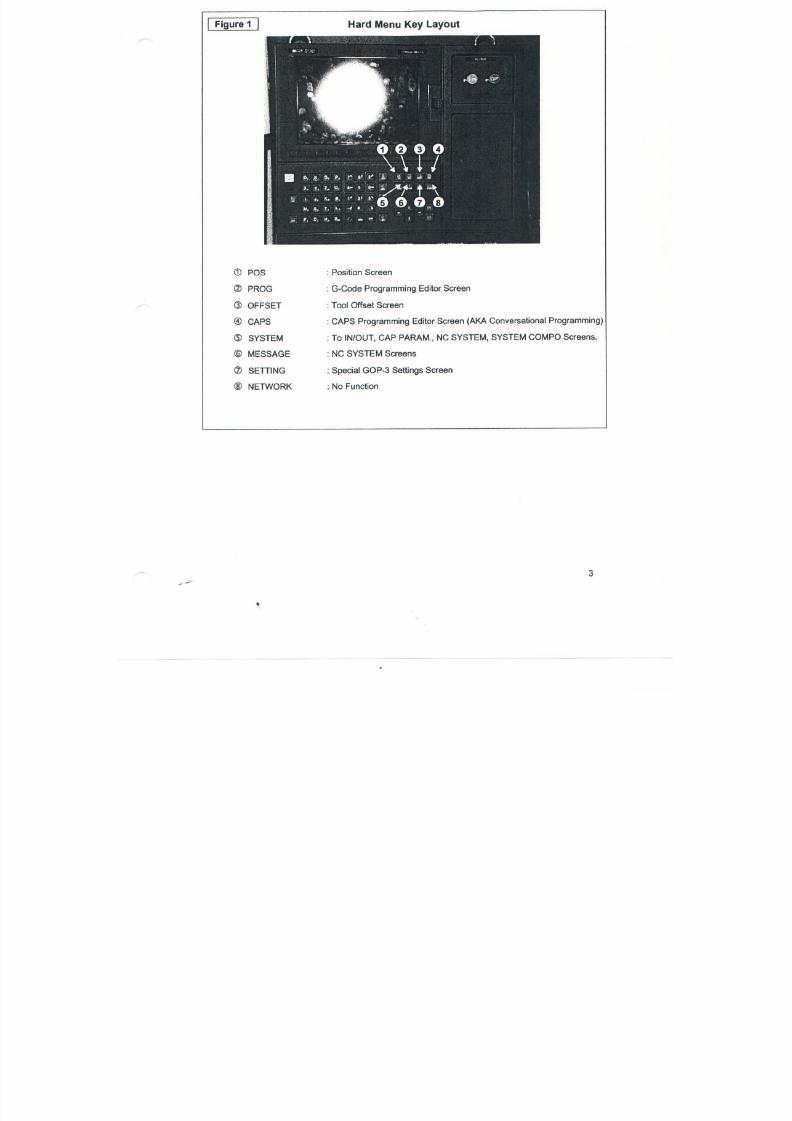
7/21/2019 MORISEIKI MAINTENANCE CLASS
http://slidepdf.com/reader/full/moriseiki-maintenance-class 380/409
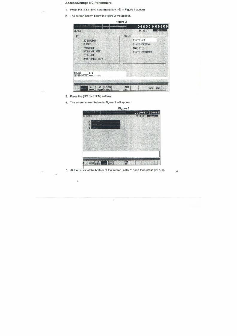
7/21/2019 MORISEIKI MAINTENANCE CLASS
http://slidepdf.com/reader/full/moriseiki-maintenance-class 381/409
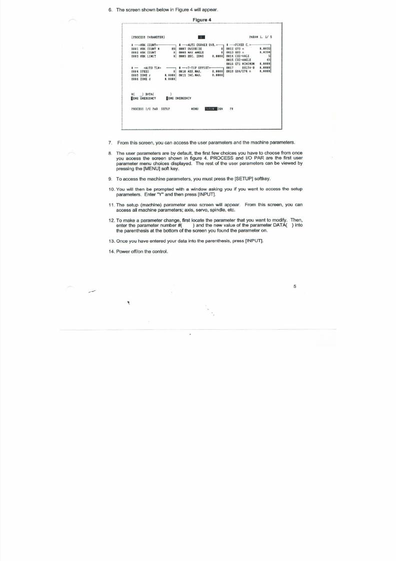
7/21/2019 MORISEIKI MAINTENANCE CLASS
http://slidepdf.com/reader/full/moriseiki-maintenance-class 382/409
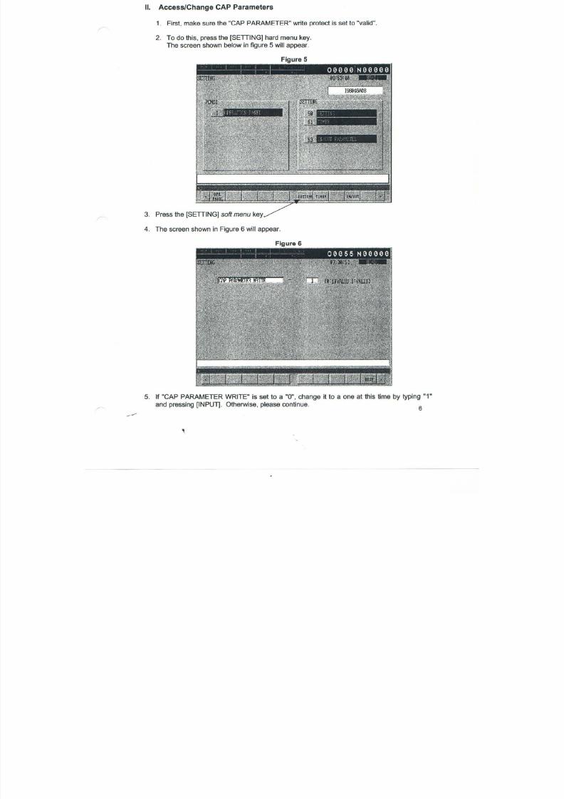
7/21/2019 MORISEIKI MAINTENANCE CLASS
http://slidepdf.com/reader/full/moriseiki-maintenance-class 383/409
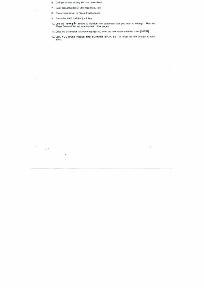
7/21/2019 MORISEIKI MAINTENANCE CLASS
http://slidepdf.com/reader/full/moriseiki-maintenance-class 384/409
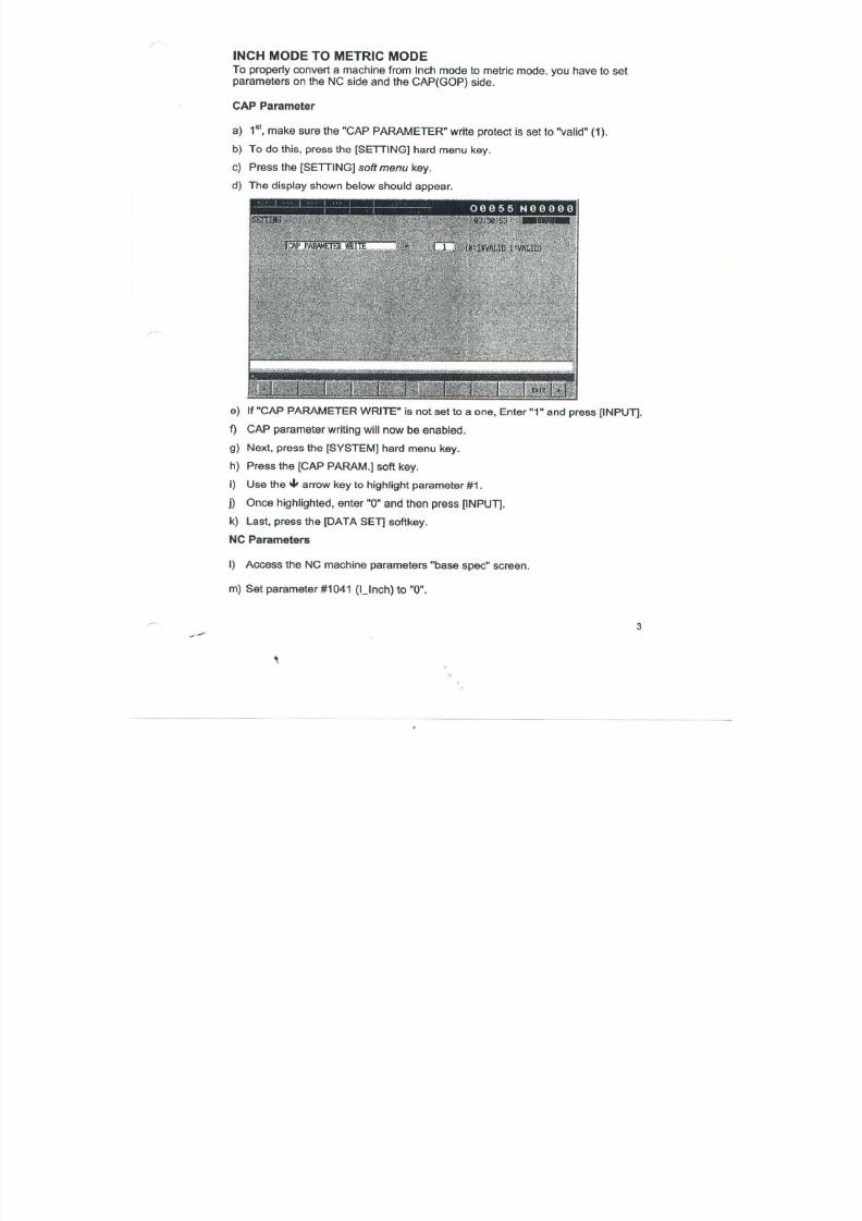
7/21/2019 MORISEIKI MAINTENANCE CLASS
http://slidepdf.com/reader/full/moriseiki-maintenance-class 385/409

7/21/2019 MORISEIKI MAINTENANCE CLASS
http://slidepdf.com/reader/full/moriseiki-maintenance-class 386/409
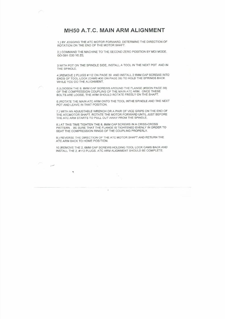
7/21/2019 MORISEIKI MAINTENANCE CLASS
http://slidepdf.com/reader/full/moriseiki-maintenance-class 387/409
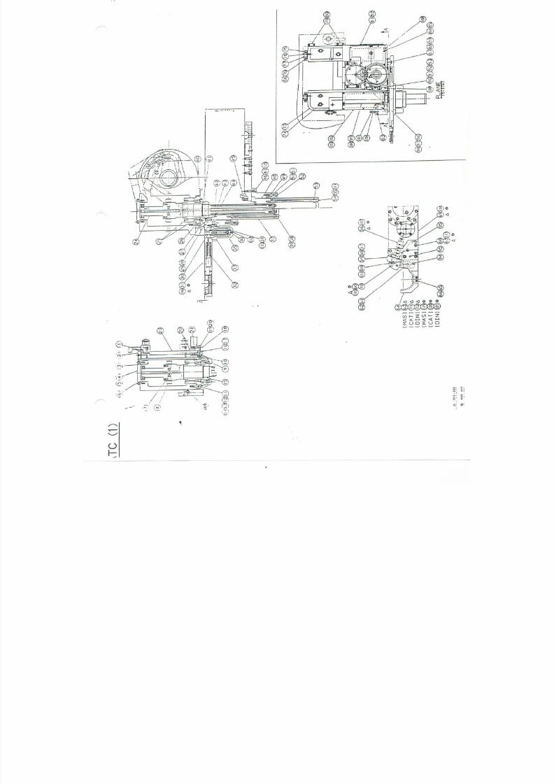
7/21/2019 MORISEIKI MAINTENANCE CLASS
http://slidepdf.com/reader/full/moriseiki-maintenance-class 388/409
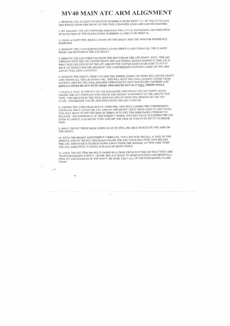
7/21/2019 MORISEIKI MAINTENANCE CLASS
http://slidepdf.com/reader/full/moriseiki-maintenance-class 389/409

7/21/2019 MORISEIKI MAINTENANCE CLASS
http://slidepdf.com/reader/full/moriseiki-maintenance-class 390/409
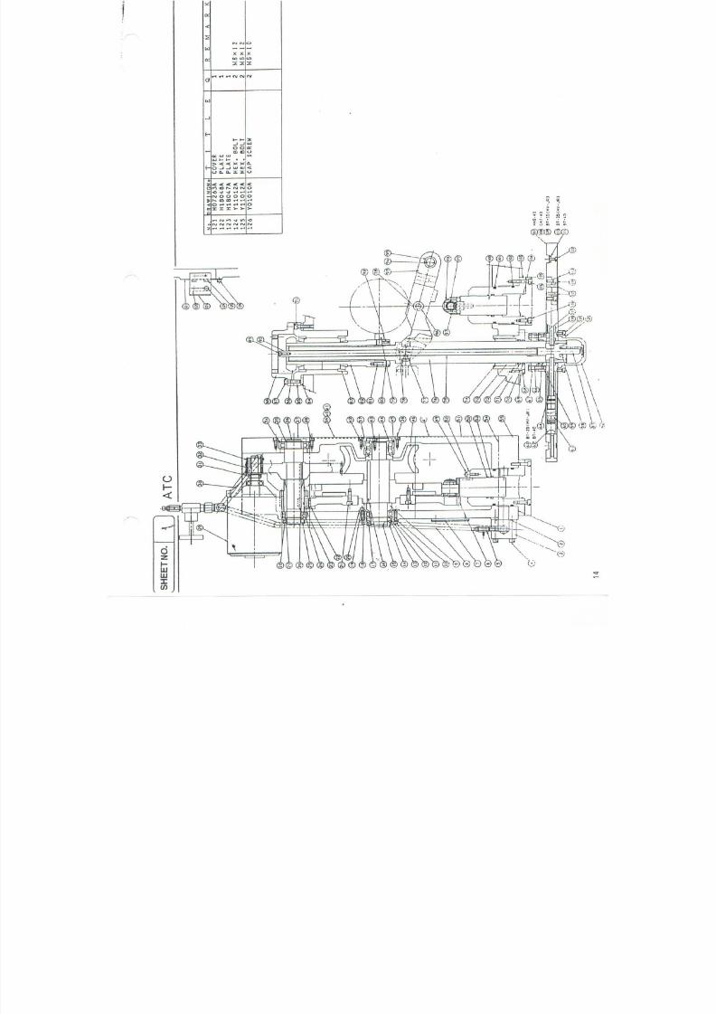
7/21/2019 MORISEIKI MAINTENANCE CLASS
http://slidepdf.com/reader/full/moriseiki-maintenance-class 391/409

7/21/2019 MORISEIKI MAINTENANCE CLASS
http://slidepdf.com/reader/full/moriseiki-maintenance-class 392/409
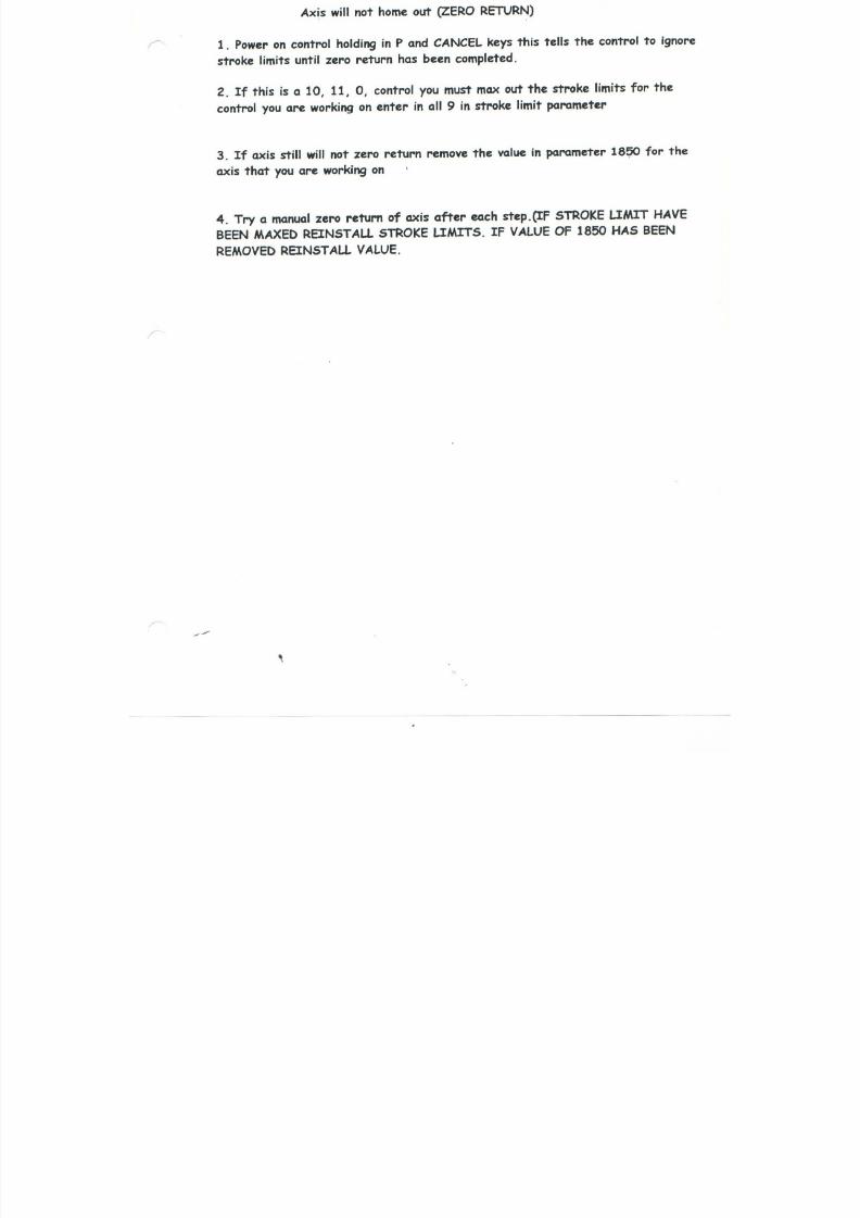
7/21/2019 MORISEIKI MAINTENANCE CLASS
http://slidepdf.com/reader/full/moriseiki-maintenance-class 393/409
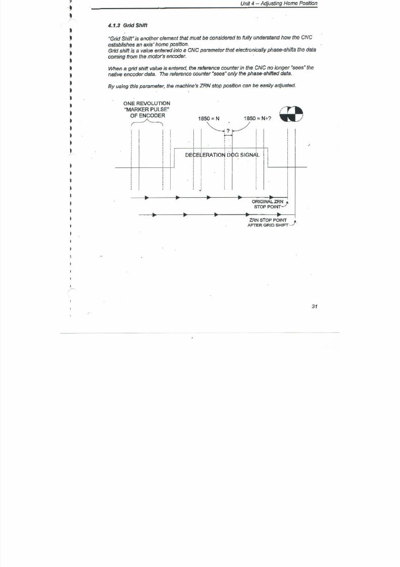
7/21/2019 MORISEIKI MAINTENANCE CLASS
http://slidepdf.com/reader/full/moriseiki-maintenance-class 394/409
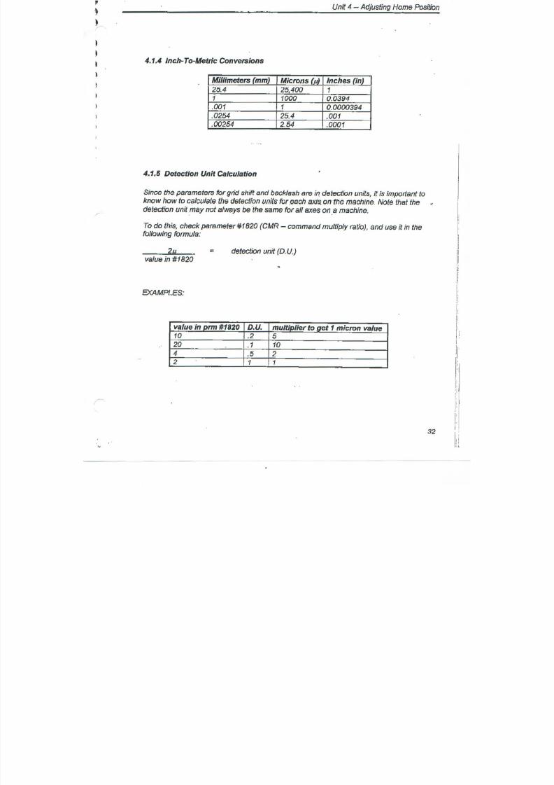
7/21/2019 MORISEIKI MAINTENANCE CLASS
http://slidepdf.com/reader/full/moriseiki-maintenance-class 395/409

7/21/2019 MORISEIKI MAINTENANCE CLASS
http://slidepdf.com/reader/full/moriseiki-maintenance-class 396/409
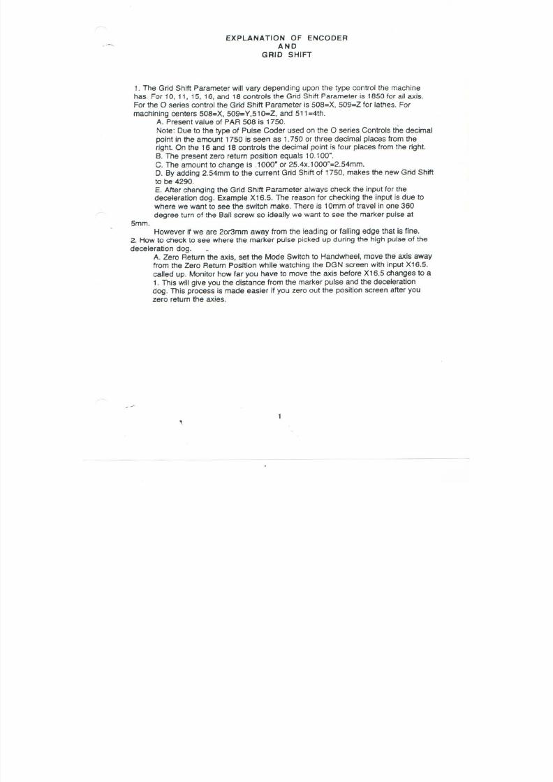
7/21/2019 MORISEIKI MAINTENANCE CLASS
http://slidepdf.com/reader/full/moriseiki-maintenance-class 397/409
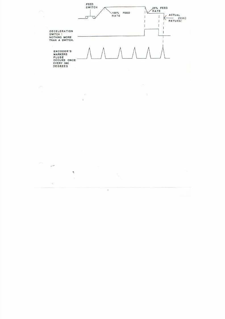
7/21/2019 MORISEIKI MAINTENANCE CLASS
http://slidepdf.com/reader/full/moriseiki-maintenance-class 398/409
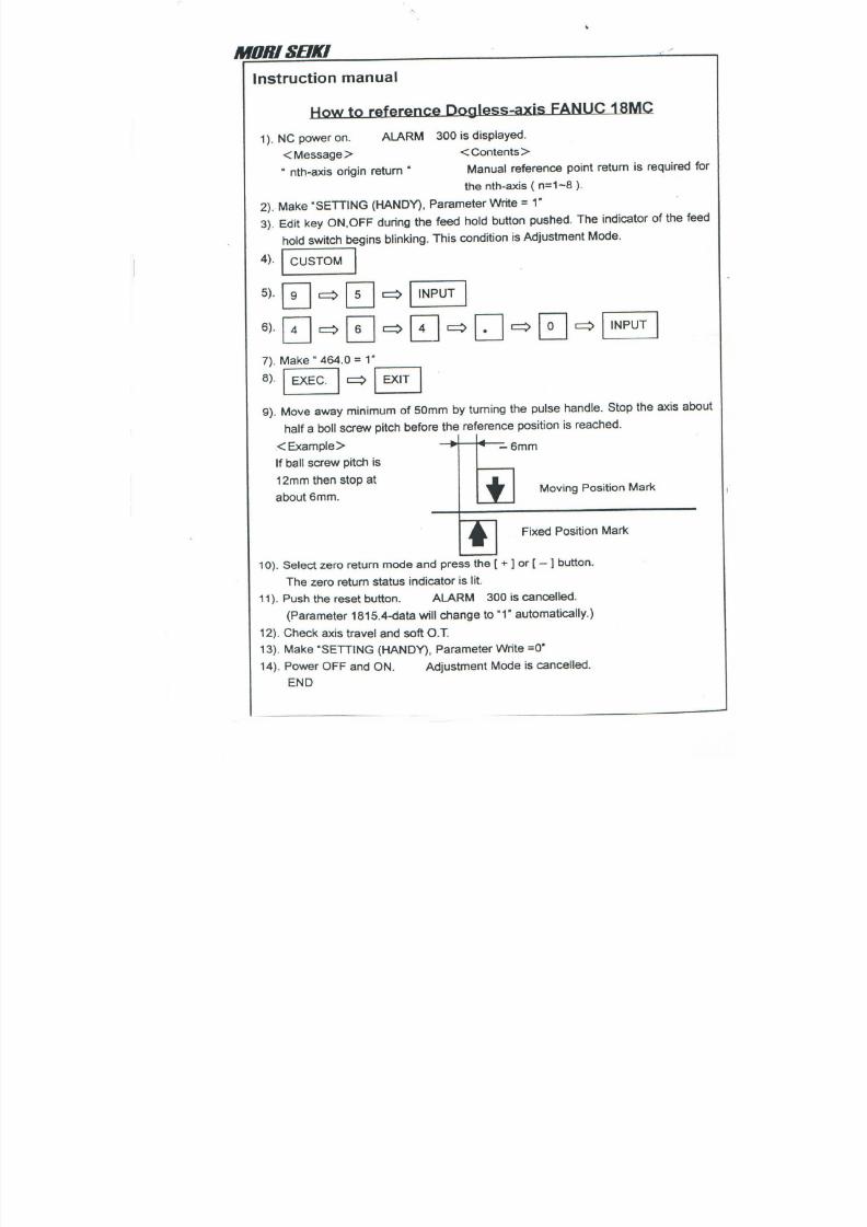
7/21/2019 MORISEIKI MAINTENANCE CLASS
http://slidepdf.com/reader/full/moriseiki-maintenance-class 399/409
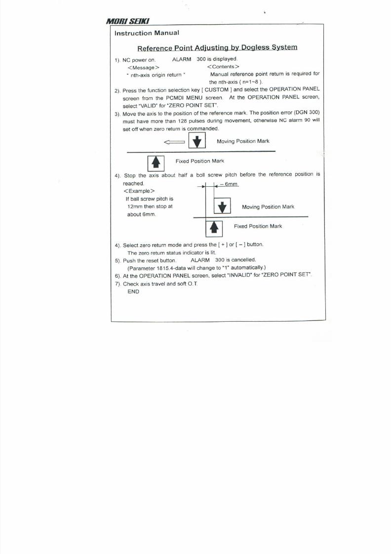
7/21/2019 MORISEIKI MAINTENANCE CLASS
http://slidepdf.com/reader/full/moriseiki-maintenance-class 400/409

7/21/2019 MORISEIKI MAINTENANCE CLASS
http://slidepdf.com/reader/full/moriseiki-maintenance-class 401/409
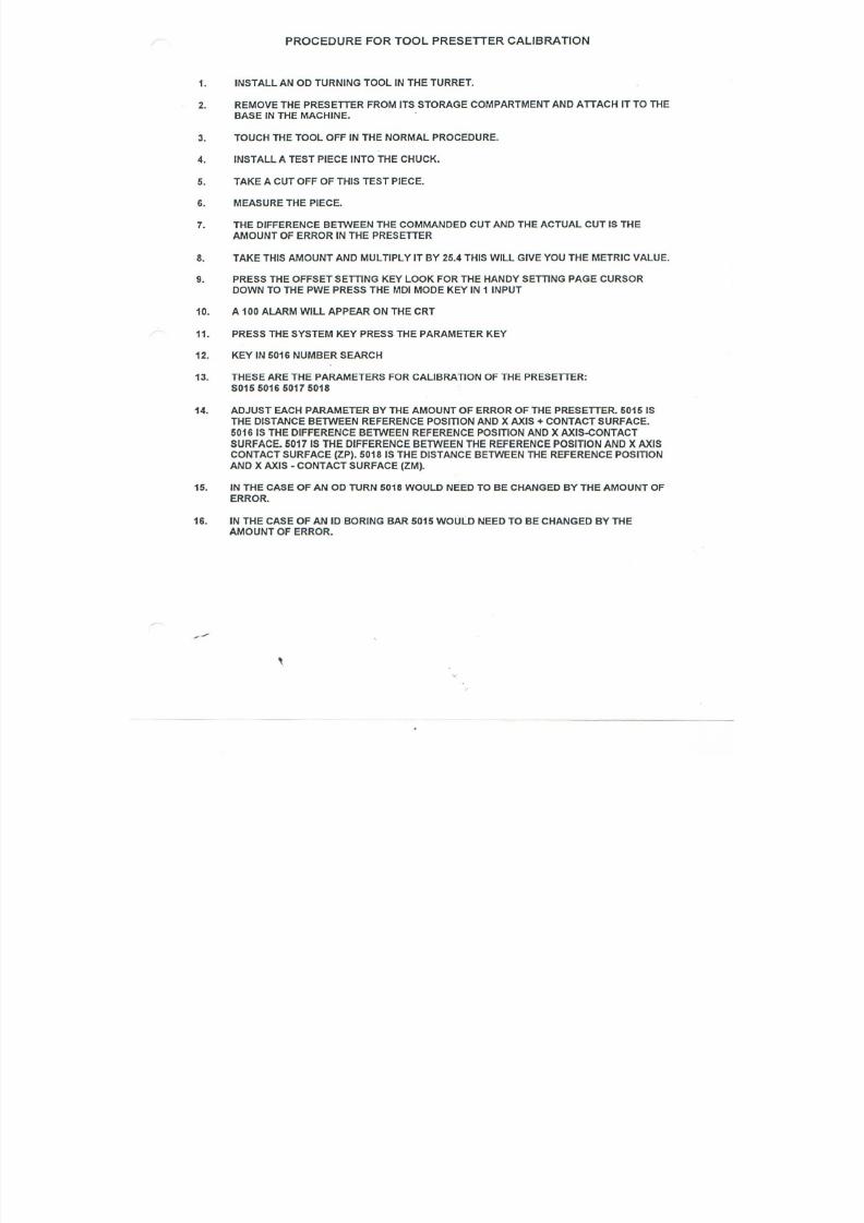
7/21/2019 MORISEIKI MAINTENANCE CLASS
http://slidepdf.com/reader/full/moriseiki-maintenance-class 402/409
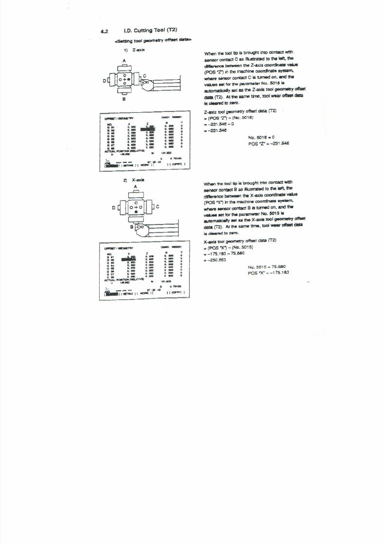
7/21/2019 MORISEIKI MAINTENANCE CLASS
http://slidepdf.com/reader/full/moriseiki-maintenance-class 403/409
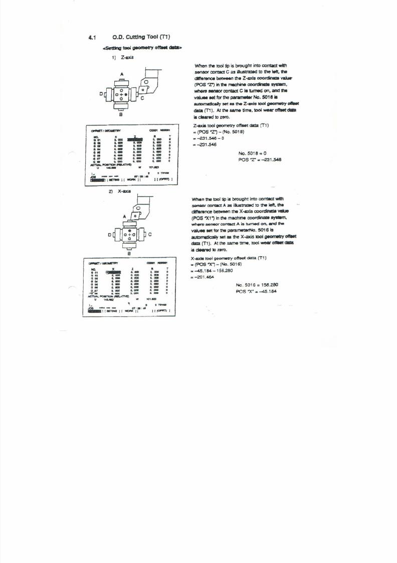
7/21/2019 MORISEIKI MAINTENANCE CLASS
http://slidepdf.com/reader/full/moriseiki-maintenance-class 404/409
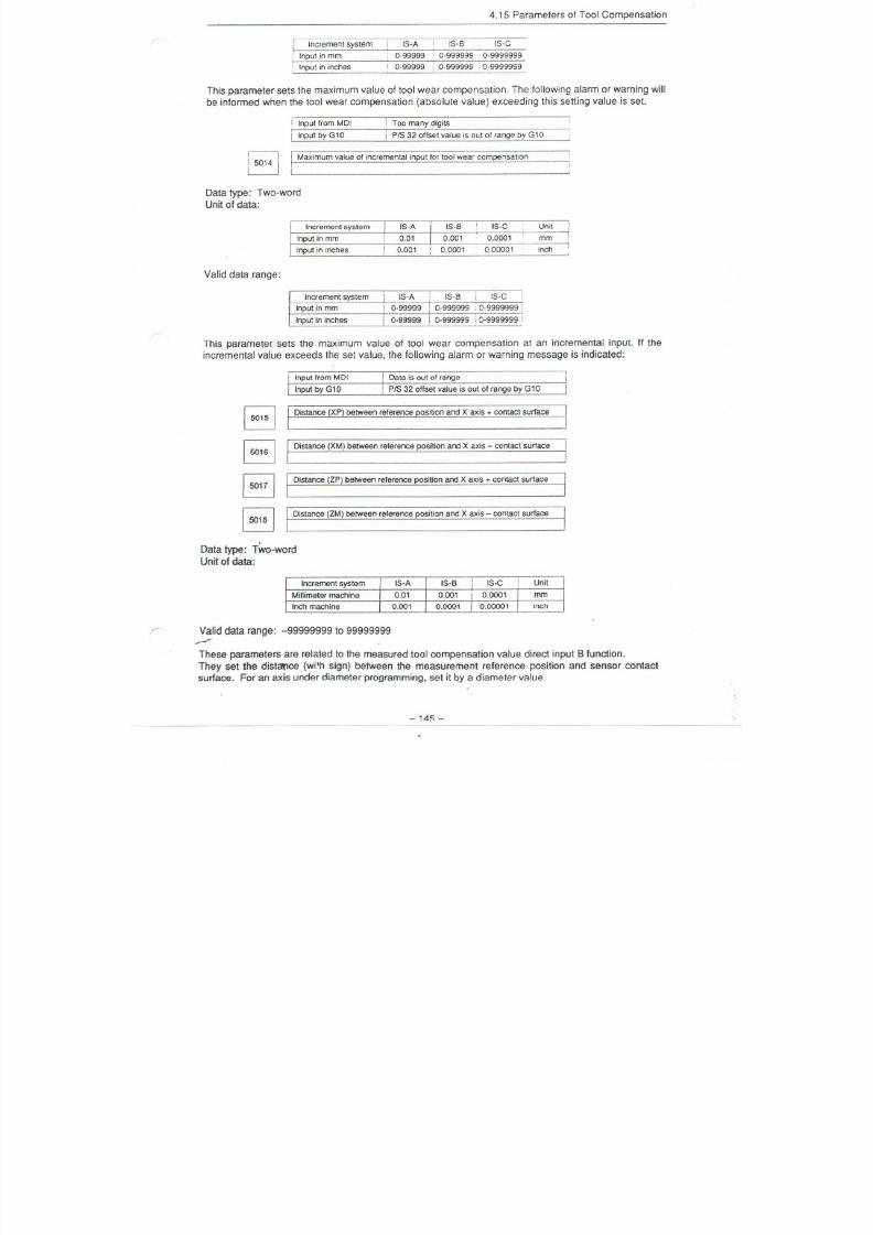
7/21/2019 MORISEIKI MAINTENANCE CLASS
http://slidepdf.com/reader/full/moriseiki-maintenance-class 405/409
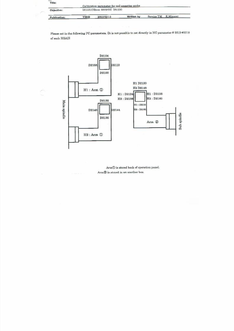
7/21/2019 MORISEIKI MAINTENANCE CLASS
http://slidepdf.com/reader/full/moriseiki-maintenance-class 406/409
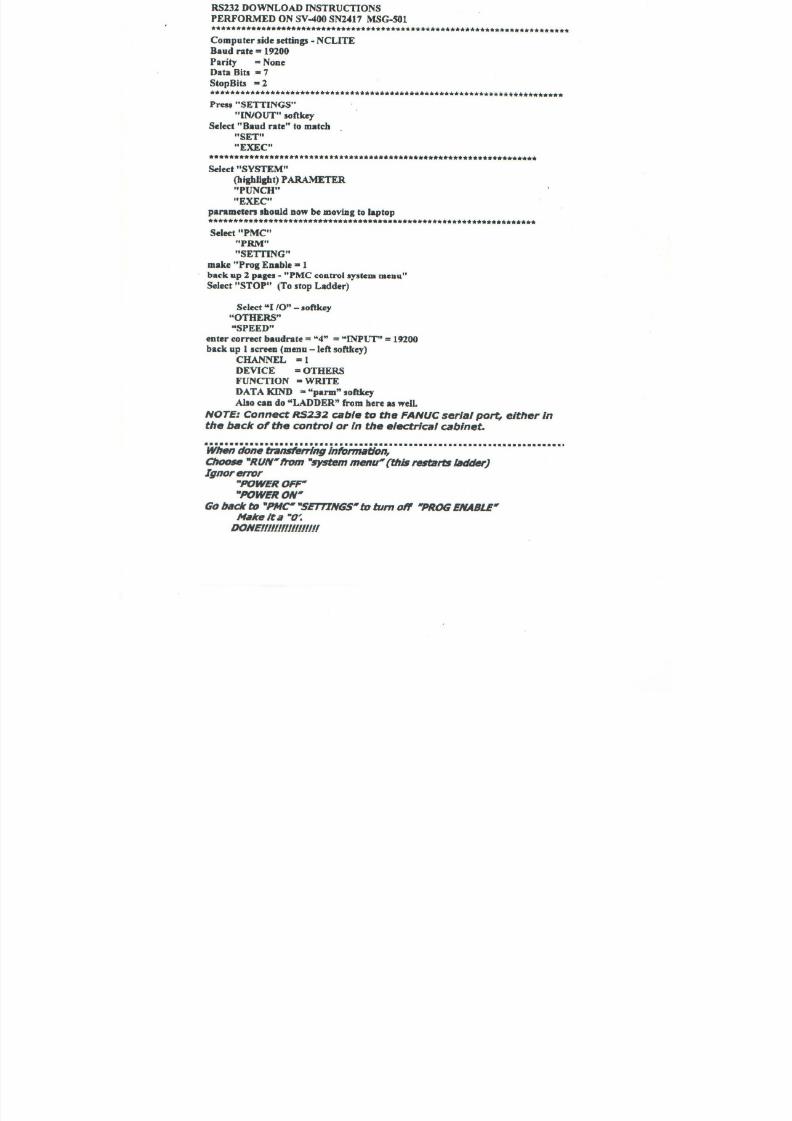
7/21/2019 MORISEIKI MAINTENANCE CLASS
http://slidepdf.com/reader/full/moriseiki-maintenance-class 407/409
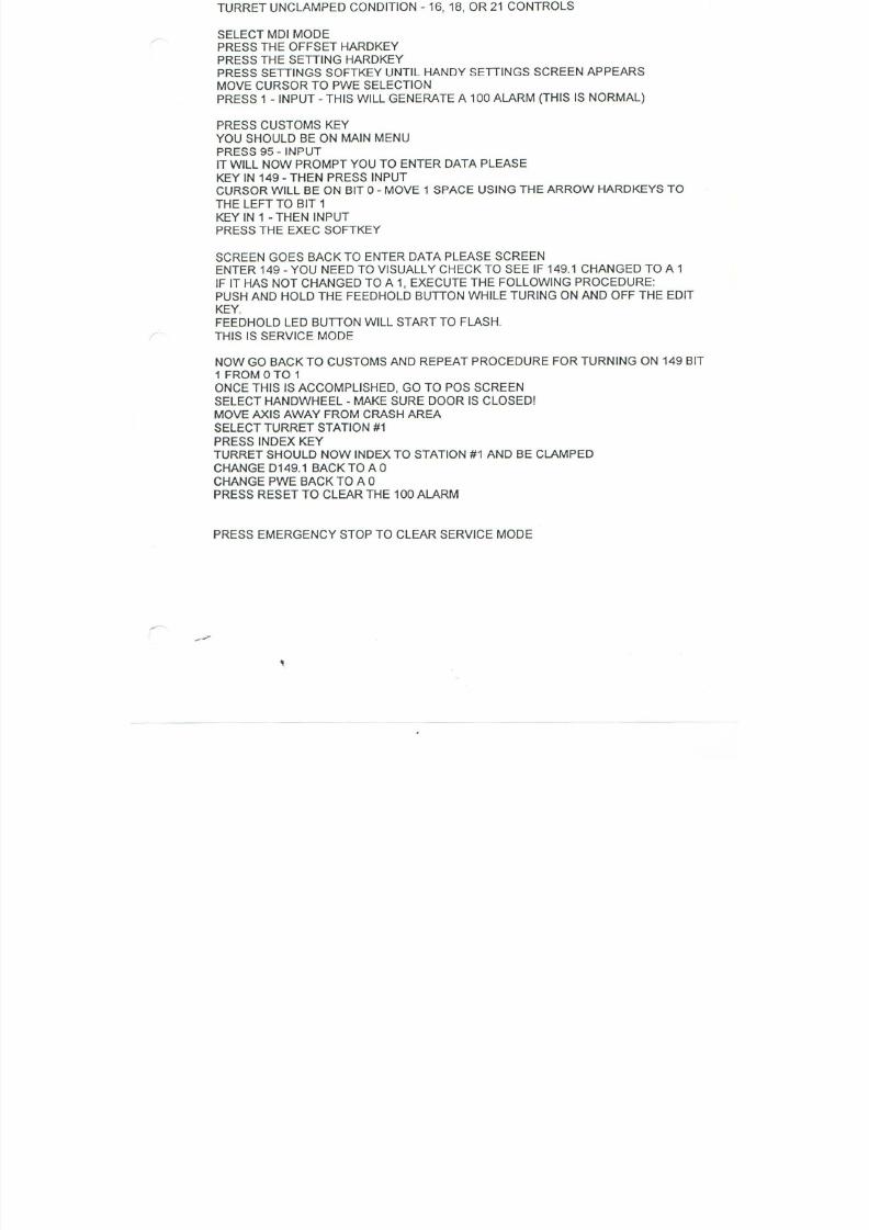
7/21/2019 MORISEIKI MAINTENANCE CLASS
http://slidepdf.com/reader/full/moriseiki-maintenance-class 408/409
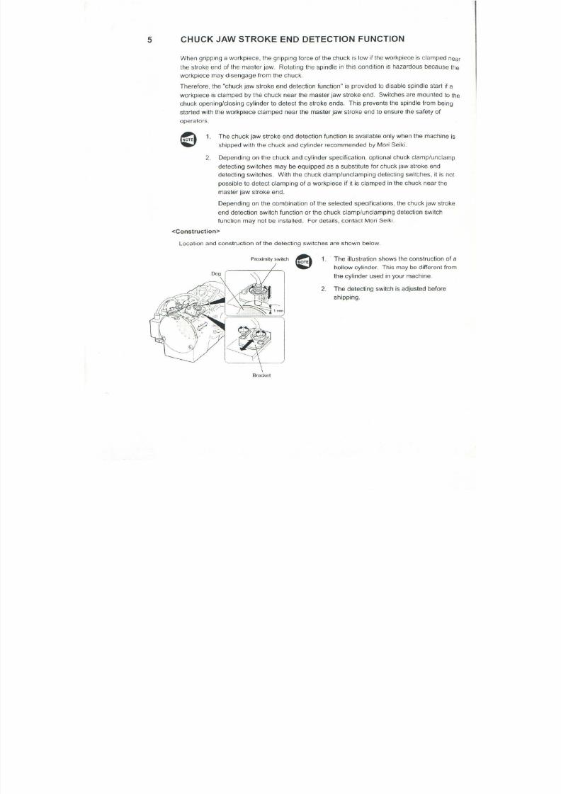
7/21/2019 MORISEIKI MAINTENANCE CLASS
http://slidepdf.com/reader/full/moriseiki-maintenance-class 409/409