Embed Size (px)
Citation preview
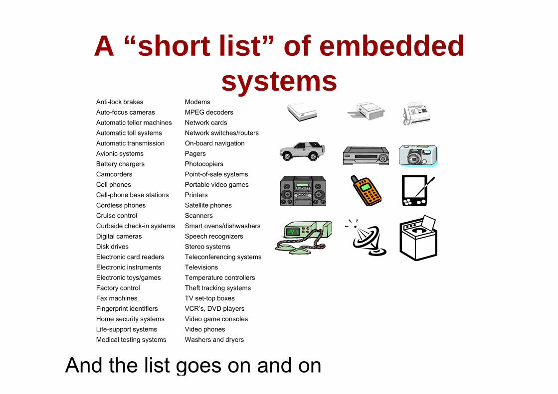
A “short list” of embedded systems
Anti-lock brakes ModemsAuto-focus camerasAutomatic teller machinesAutomatic toll systemsAutomatic transmissionA ionic s stems
MPEG decodersNetwork cardsNetwork switches/routersOn-board navigationPagersAvionic systems
Battery chargersCamcordersCell phonesCell-phone base stations
PagersPhotocopiersPoint-of-sale systemsPortable video gamesPrintersCell phone base stations
Cordless phonesCruise controlCurbside check-in systemsDigital cameras
PrintersSatellite phonesScannersSmart ovens/dishwashersSpeech recognizers
Disk drivesElectronic card readersElectronic instrumentsElectronic toys/gamesF t t l
Stereo systemsTeleconferencing systemsTelevisionsTemperature controllersTh ft t ki tFactory control
Fax machinesFingerprint identifiersHome security systemsLife-support systems
Theft tracking systemsTV set-top boxesVCR’s, DVD playersVideo game consolesVideo phones
And the list goes on and on
Life support systemsMedical testing systems
Video phonesWashers and dryers
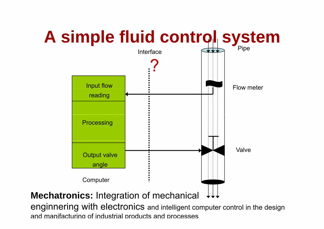
A simple fluid control systemA simple fluid control systemPipeInterface
?Flow meterInput flow
?Flow meterp
reading
Processing
ValveOutput valve
angle
Computer
angle
M h t i I t ti f h i lMechatronics: Integration of mechanicalenginnering with electronics and intelligent computer control in the design and manifacturing of industrial products and processes
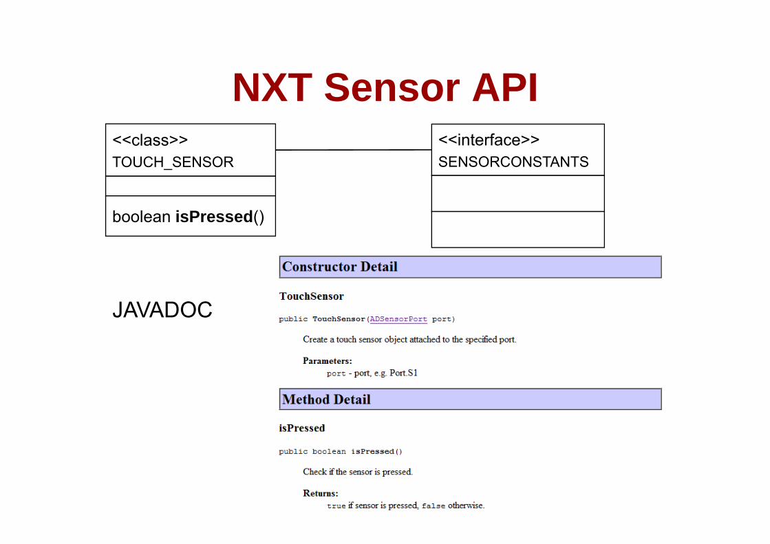
NXT Sensor APINXT Sensor API<<class>> <<interface>>TOUCH_SENSOR
b l i P d()
SENSORCONSTANTS
boolean isPressed()
JAVADOC
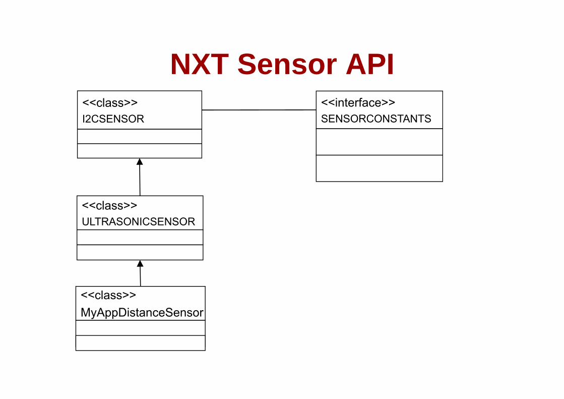
NXT Sensor APINXT Sensor API<<class>> <<interface>>I2CSENSOR SENSORCONSTANTS
<<class>>ULTRASONICSENSOR
<<class>>MyAppDistanceSensor
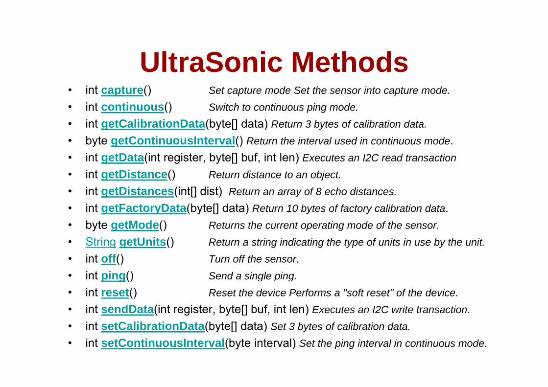
UltraSonic MethodsUltraSonic Methods• int capture() Set capture mode Set the sensor into capture mode. • int continuous() Switch to continuous ping mode• int continuous() Switch to continuous ping mode. • int getCalibrationData(byte[] data) Return 3 bytes of calibration data. • byte getContinuousInterval() Return the interval used in continuous mode. • int getData(int register, byte[] buf, int len) Executes an I2C read transaction• int getDistance() Return distance to an object. • int getDistances(int[] dist) Return an array of 8 echo distancesint getDistances(int[] dist) Return an array of 8 echo distances. • int getFactoryData(byte[] data) Return 10 bytes of factory calibration data.• byte getMode() Returns the current operating mode of the sensor.
St i tU it ()• String getUnits() Return a string indicating the type of units in use by the unit. • int off() Turn off the sensor. • int ping() Send a single ping. p g() g p g• int reset() Reset the device Performs a "soft reset" of the device. • int sendData(int register, byte[] buf, int len) Executes an I2C write transaction. • int setCalibrationData(byte[] data) Set 3 bytes of calibration data• int setCalibrationData(byte[] data) Set 3 bytes of calibration data. • int setContinuousInterval(byte interval) Set the ping interval in continuous mode.
Sensors & ActuatorsSensors & Actuators
• Acknowledgements
Hardware of the sensor networkS d i h l h d-- Sensors and peripheral hardware
-- Lin GuSept 8, 2003

Sensors and ActuatorsSensors and Actuators• Transducer: “A device which transforms
energy from one domain (magnetic, thermal mechanical optical chemicalthermal, mechanical, optical, chemical, electrical) into another”
• Sensors: “devices which monitor aSensors: devices which monitor a parameter of a system, hopefully without disturbing that parameter.”
• Actuators: “devices which impose a state on a system, hopefully Sensor?independent of the load applied to them” Actuator?
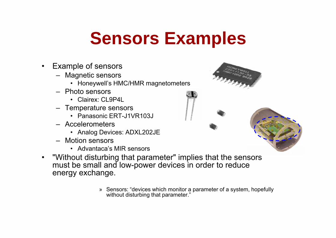
Sensors ExamplesSensors Examples• Example of sensors• Example of sensors
– Magnetic sensors• Honeywell’s HMC/HMR magnetometers
– Photo sensors– Photo sensors• Clairex: CL9P4L
– Temperature sensors• Panasonic ERT-J1VR103J
– Accelerometers• Analog Devices: ADXL202JE
– Motion sensors• Advantaca’s MIR sensors
• "Without disturbing that parameter" implies that the sensors must be small and low-power devices in order to reduce energy exchangeenergy exchange.
» Sensors: “devices which monitor a parameter of a system, hopefully without disturbing that parameter.”
Sensors TypesSensors Types
• Motion / Rotation• AccelerationAcceleration• Force, Torque, Pressure• Flow• Temperature• Temperature• Proximity• Light• Image• Image• …
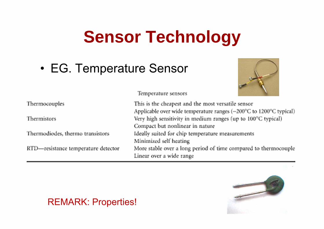
Sensor TechnologySensor Technology
• EG. Temperature Sensor
REMARK: Properties!
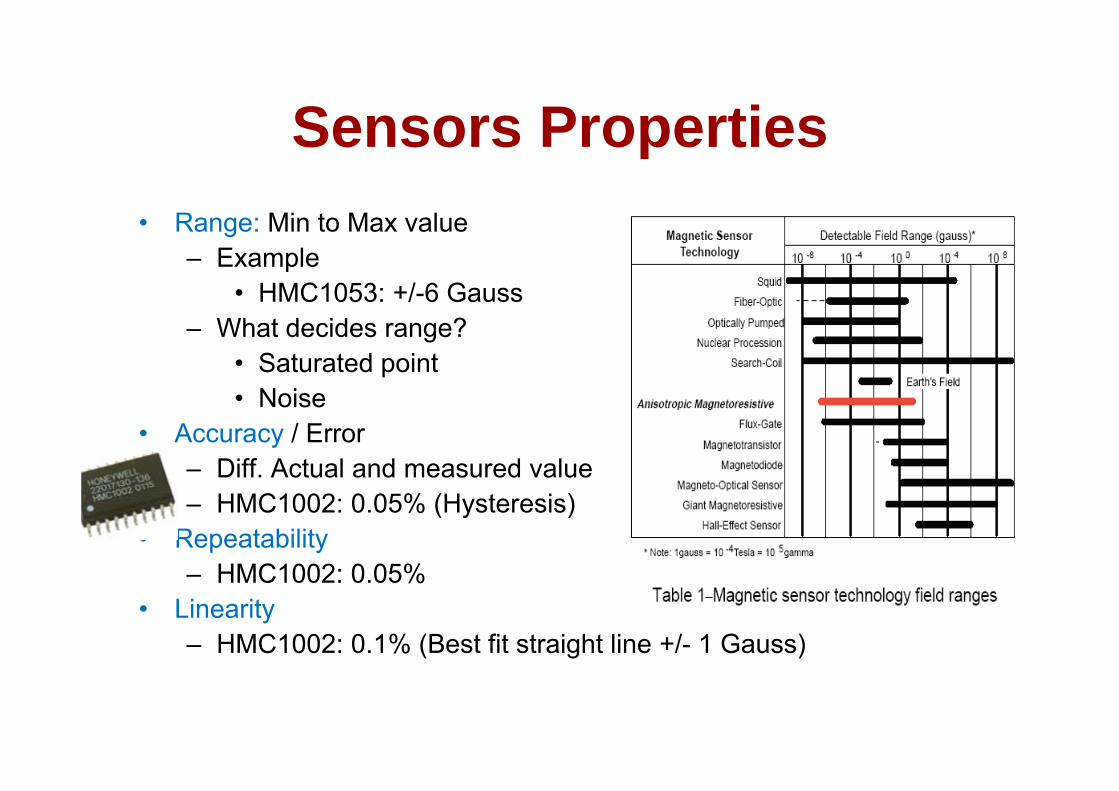
Sensors PropertiesSensors PropertiesR Mi t M l• Range: Min to Max value– Example
• HMC1053: +/-6 Gauss– What decides range?
• Saturated point• Noise• Noise
• Accuracy / Error– Diff. Actual and measured value– HMC1002: 0.05% (Hysteresis)
• Repeatability– HMC1002: 0 05%– HMC1002: 0.05%
• Linearity– HMC1002: 0.1% (Best fit straight line +/- 1 Gauss)
Sensors PropertiesSensors PropertiesS iti it• Sensitivity– How output reflects input?
HMC1053 1 V/V/– HMC1053: 1mV/V/gauss• Efficiency
R ti f th t t t th i t– Ratio of the output power to the input power– Important for actuators
R l ti• Resolution– Determined by sensitivity and noise level
M i i l l– Measuring noise level• SNR• Noise floor (High noise floor does not mean “useless”)( g )
– HMC1002: 27uGauss

Sensors PropertiesSensors PropertiesR ti– Response time
• How fast the output reaches a fraction of the expected signal levelexpected signal level
– Overshoot• How much does the output signal go beyond the• How much does the output signal go beyond the
expected signal level– Drift and stabilityDrift and stability
• How the output signal varies slowly compared to time
– Offset• The output when there is no inputp p

Sensor PropertiesSensor Properties
ActuatorsActuators
• Examples of Actuators– Motor (impose a torque)( p q )– Pumps (impose pressure or fluid velocity)
A t t b f l l d• Actuators may be powerful, large, and complicated
» Actuators: “devices which impose a state on a psystem, hopefully independent of the load applied to them”
ActuatorsActuators
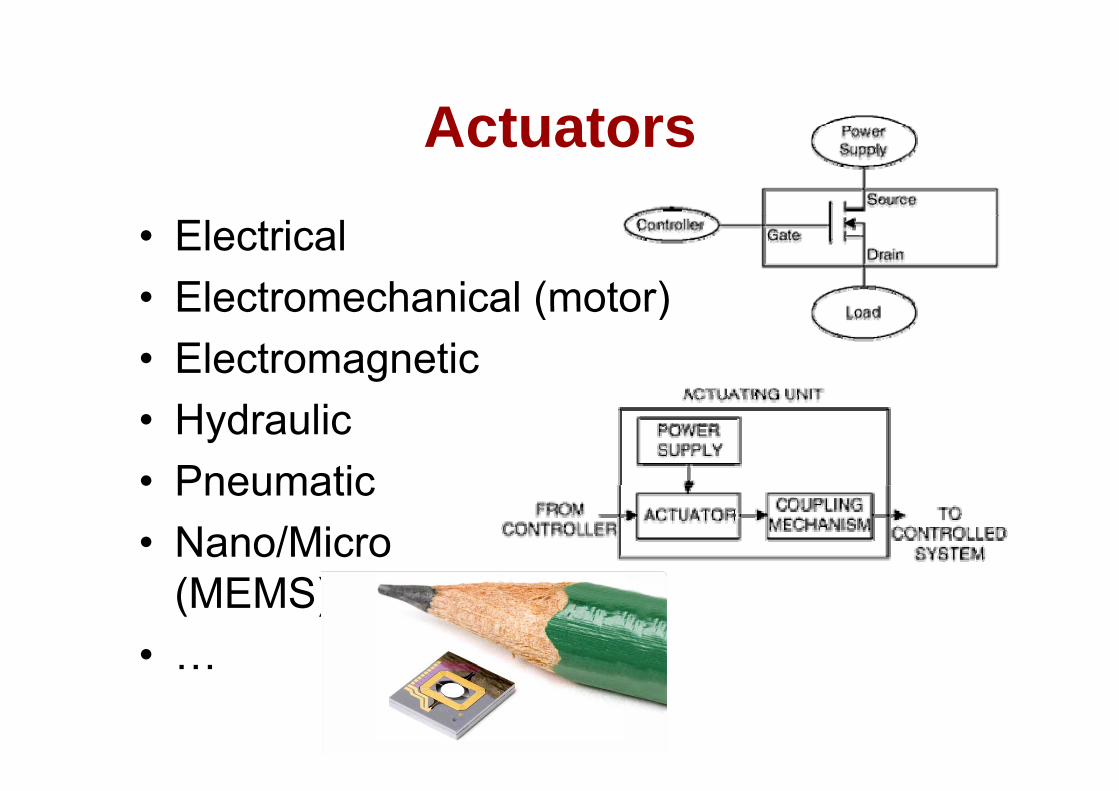
• Electrical• Electromechanical (motor)Electromechanical (motor)• Electromagnetic• Hydraulic• Pneumatic• Pneumatic• Nano/Micro
(MEMS)• ……
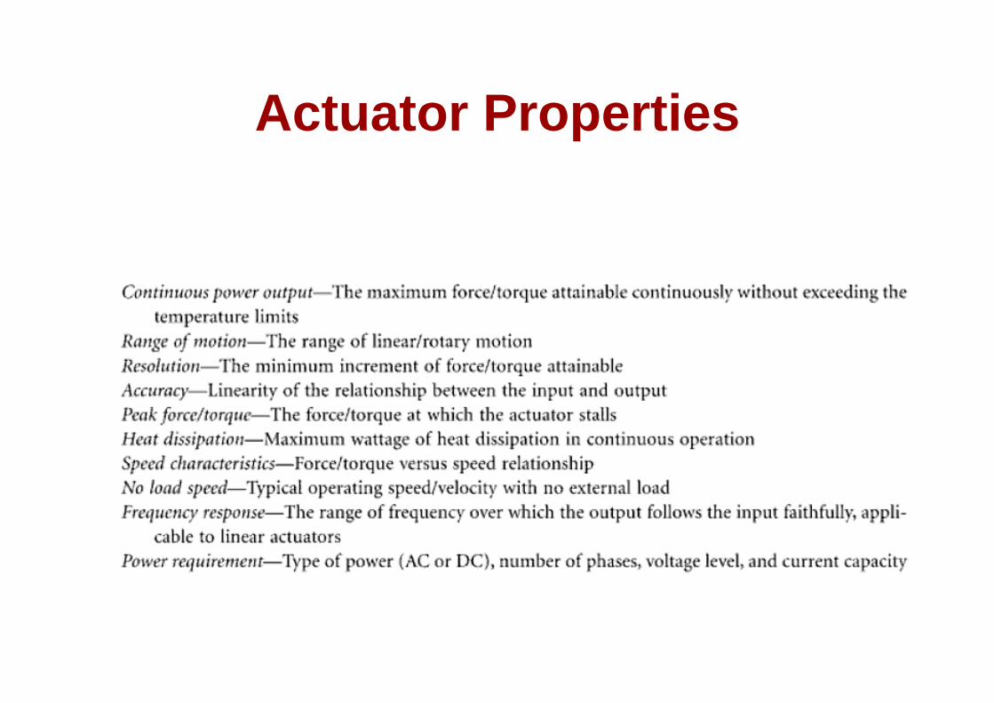
Actuator PropertiesActuator Properties
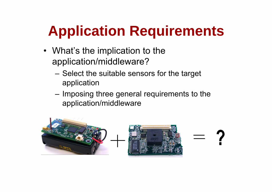
Application RequirementsApplication Requirements• What’s the implication to theWhat s the implication to the
application/middleware?– Select the suitable sensors for the target– Select the suitable sensors for the target
application– Imposing three general requirements to theImposing three general requirements to the
application/middleware
Application RequirementsApplication RequirementsR i t 1 t• Requirement 1: sensor part– Application designer must be aware of the
properties of sensorsproperties of sensors• How to handle imperfect sensor devices
– Error, offset, drift, …– Repeatability– Sensors vary
• Requirement 2: sensor reading• Requirement 2: sensor reading– Application designers must be aware of the errors
introduced by the mote hardware?y• The effect of AD converting• The effect of signal amplification/distortion

Application RequirementsApplication Requirements• Requirement 3: interaction
– The application designer must be aware of the interaction of multiple sensors and the mote hardware
How to avoid race conditions on hardware wires and• How to avoid race conditions on hardware wires and software event handlers?
• How to control the mutual interaction of various hardware components?
– Example: radio component increases the noise floor of the motion sensor
• Can we make the sensors complement with each other to achieve better sensing?
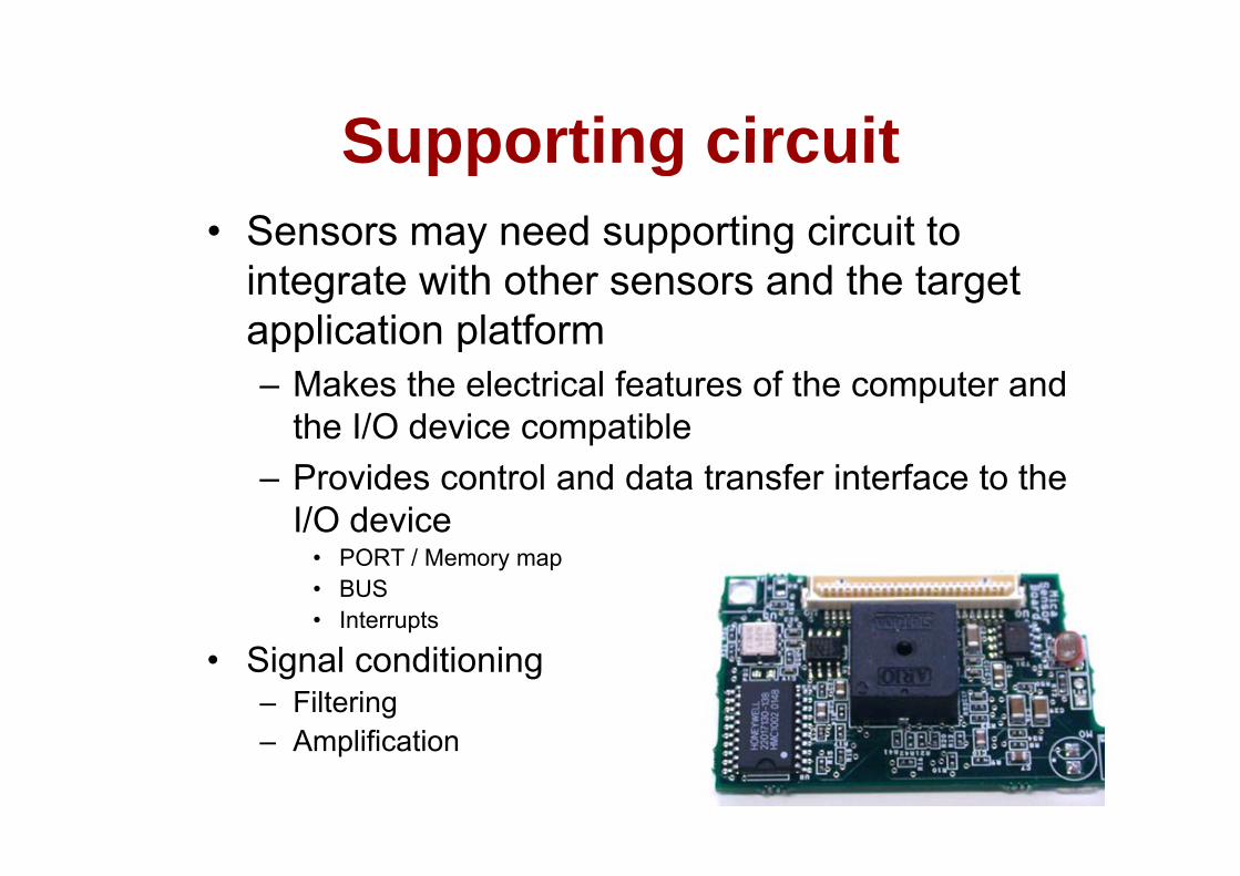
Supporting circuitSupporting circuit• Sensors may need supporting circuit toSensors may need supporting circuit to
integrate with other sensors and the target application platformapplication platform– Makes the electrical features of the computer and
the I/O device compatiblethe I/O device compatible– Provides control and data transfer interface to the
I/O device• PORT / Memory map• BUS • Interrupts
• Signal conditioning– Filtering
Amplification– Amplification
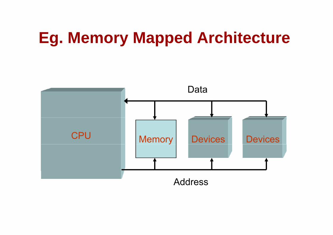
Eg Memory Mapped ArchitectureEg. Memory Mapped Architecture
DataData
MemoryCPU DevicesDevicesy
Address
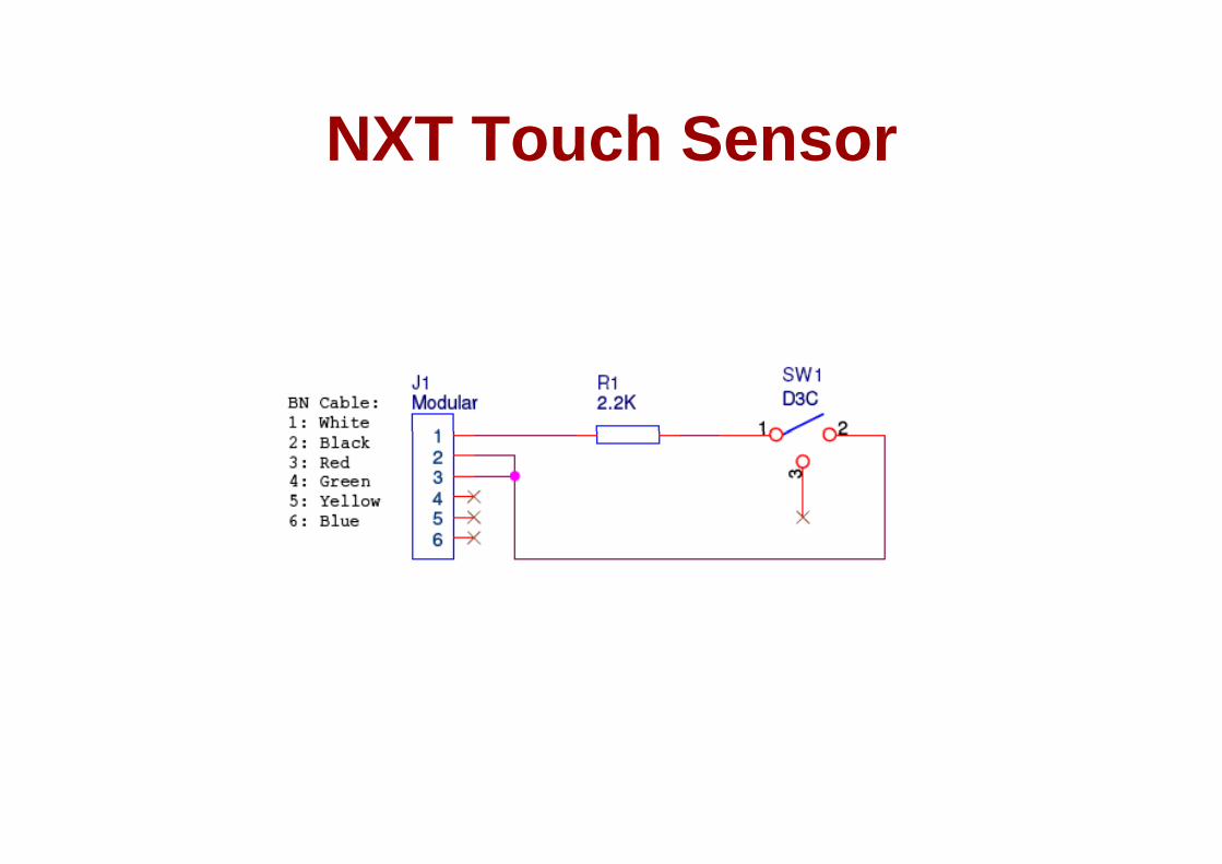
NXT Touch SensorNXT Touch Sensor
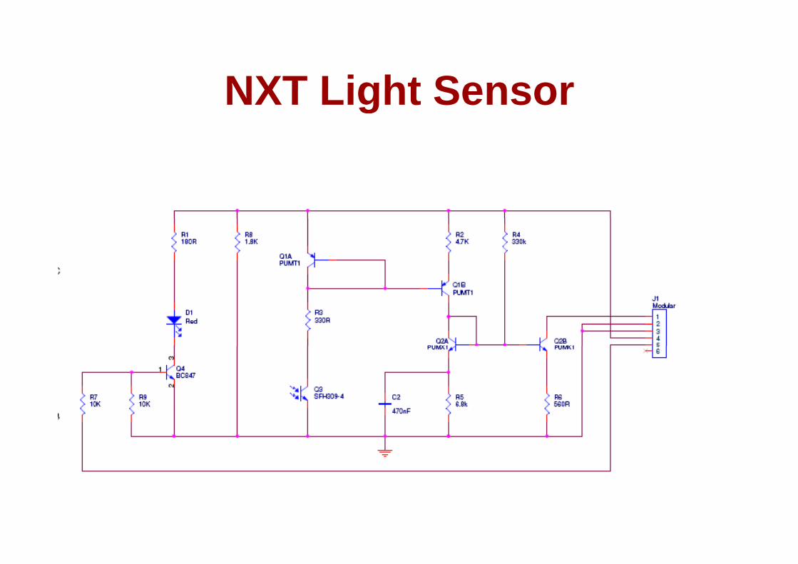
NXT Light SensorNXT Light Sensor
Device DriversDevice Drivers• Software that controls the operation of an I/OSoftware that controls the operation of an I/O
device– Uses port registers or memory map to control– Uses port registers or memory map to control
(read/write) the electronics of the device– Polling vs. Interrupt drivenPolling vs. Interrupt driven– Hardware, device and OS dependent
• http://en wikipedia org/wiki/Device driver• http://en.wikipedia.org/wiki/Device_driver

Sensors Data Processing Example
M ti i MIR• Motion sensor using MIR• Micro Impulse Radar
– TWR-ISM-002• Output (Advantaca’s)
– Analog– Digital
• Packaging– 51-pin connector
• Fine tuned receiving gate can potentially detect moving objects at a certain distance
• Is it a typical sensor?

Post processingPost-processing
• Post-processing (“POST” ~after raw data hasPost processing ( POST after raw data has been collected) – Process the sensor reading to make it useful toProcess the sensor reading to make it useful to
the application– The complexity varies from simple threshold e co p e y a es o s p e es o d
algorithm to full-fledged signal processing and pattern recognition
• (but pre – before application decides on actions)actions)
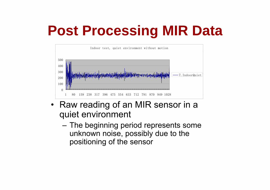
Post Processing MIR DataPost Processing MIR DataIndoor test, quiet environment without motion
300
400
500
0
100
200
1 80 159 238 317 396 475 554 633 712 791 870 949 1028
7.IndoorQuiet
• Raw reading of an MIR sensor in a quiet environment
1 80 159 238 317 396 475 554 633 712 791 870 949 1028
quiet environment– The beginning period represents some
unknown noise, possibly due to the positioning of the sensor
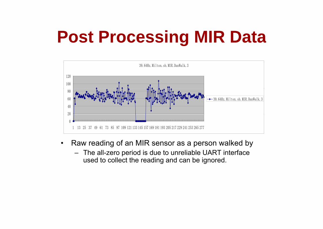
Post Processing MIR DataPost Processing MIR Data39.64Hz.Milton.sb.MIR.DanWalk.3
100
120
20
40
60
80
39.64Hz.Milton.sb.MIR.DanWalk.3
R di f MIR lk d b
0
20
1 13 25 37 49 61 73 85 97 109 121 133 145 157 169 181 193 205 217 229 241 253 265 277
• Raw reading of an MIR sensor as a person walked by– The all-zero period is due to unreliable UART interface
used to collect the reading and can be ignored.

Post Processing MIR DataPost Processing MIR Data
• Use a post-processing algorithm to transform the raw reading to what the t a s o t e a ead g to at t eapplication needs– The application needs to know whetherThe application needs to know whether
the motion of interest is detected– The post processing needs to filter out p p g
noise whenever possible

Post Processing MIR DataPost Processing MIR Data• Post-processing algorithmsPost processing algorithms
– “Moving variance” algorithm• Adapt to the environment dynamically but requires moreAdapt to the environment dynamically but requires more
computation• Designed by OSU• The basic idea is to track the changes of a statistic
variable• To avoid the complexity of moving varianceTo avoid the complexity of moving variance
computation, another statistics variable was used for mote-based moving object detectionIf “adapting” feature is not required offline modeling• If “adapting” feature is not required, offline modeling and online detection can be combined

Post Processing MIR DataPost Processing MIR DataM “M i i ” l ith• More on “Moving variance” algorithm– Calculate the variance of the samples– Example: Suppose the sensor data in a “quiet” environment is as
f llfollows
5
6
1
2
3
4
Series1
• Mean: 3V i 2 18
0
1 2 3 4 5 6 7 8 9 10 11 12
• Variance: 2.18
» This is my interpretation of OSU’s algorithm. I have not seen their code or detailed description of it.or detailed description of it.
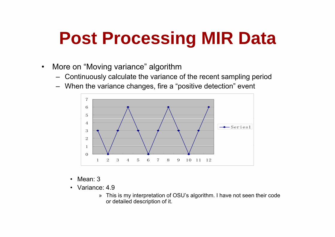
Post Processing MIR DataPost Processing MIR DataM “M i i ” l ith• More on “Moving variance” algorithm– Continuously calculate the variance of the recent sampling period– When the variance changes, fire a “positive detection” event
5
6
7
1
2
3
4Series1
0
1
1 2 3 4 5 6 7 8 9 10 11 12
• Mean: 3• Variance: 4.9
» This is my interpretation of OSU’s algorithm. I have not seen their code for detailed description of it.
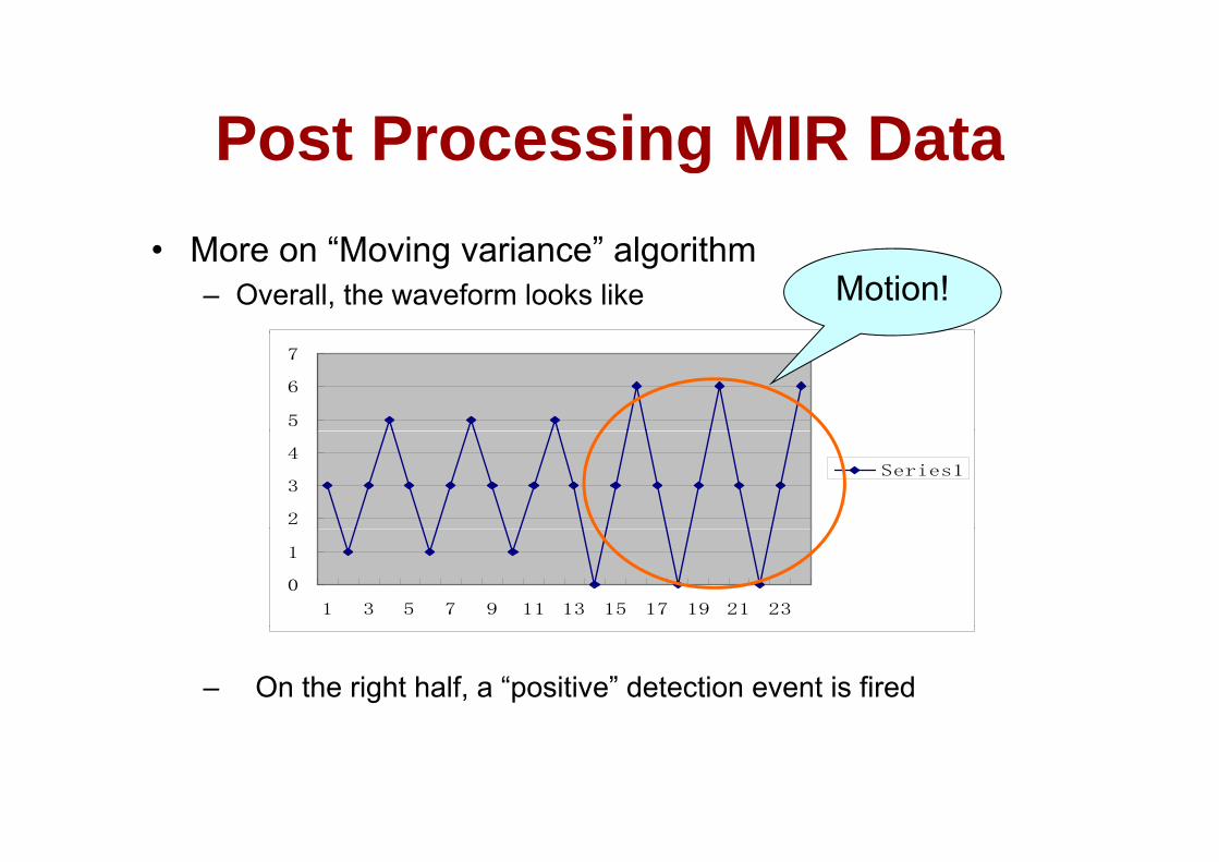
Post Processing MIR DataPost Processing MIR Data• More on “Moving variance” algorithm
– Overall, the waveform looks like Motion!
5
6
7
2
3
4Series1
0
1
1 3 5 7 9 11 13 15 17 19 21 23
– On the right half, a “positive” detection event is fired

Post Processing MIR DataPost Processing MIR Data• More on “Moving variance” algorithm
– This technique can be applied to other statistical variables
• MeanStandard deviation• Standard deviation
• MIN, MAX
– The main idea is to use the statistics in a recentThe main idea is to use the statistics in a recent sampling period to
• detect “phase change”• filter out burst noise reading
• Change in waveformChange in waveform• SIGNAL PROCESSING

A “short list” of embedded systems
Anti-lock brakes ModemsAuto-focus camerasAutomatic teller machinesAutomatic toll systemsAutomatic transmissionA ionic s stems
MPEG decodersNetwork cardsNetwork switches/routersOn-board navigationPagersAvionic systems
Battery chargersCamcordersCell phonesCell-phone base stations
PagersPhotocopiersPoint-of-sale systemsPortable video gamesPrintersCell phone base stations
Cordless phonesCruise controlCurbside check-in systemsDigital cameras
PrintersSatellite phonesScannersSmart ovens/dishwashersSpeech recognizers
Disk drivesElectronic card readersElectronic instrumentsElectronic toys/gamesF t t l
Stereo systemsTeleconferencing systemsTelevisionsTemperature controllersTh ft t ki tFactory control
Fax machinesFingerprint identifiersHome security systemsLife-support systems
Theft tracking systemsTV set-top boxesVCR’s, DVD playersVideo game consolesVideo phones
And the list goes on and on
Life support systemsMedical testing systems
Video phonesWashers and dryers
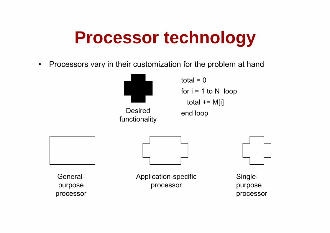
Processor technologyProcessor technology• Processors vary in their customization for the problem at hand• Processors vary in their customization for the problem at hand
total = 0for i = 1 to N loopfor i = 1 to N loop
total += M[i]end loopDesired
f i lip
functionality
General-purpose
processor
Single-purpose processor
Application-specific processor
p ocesso p ocesso
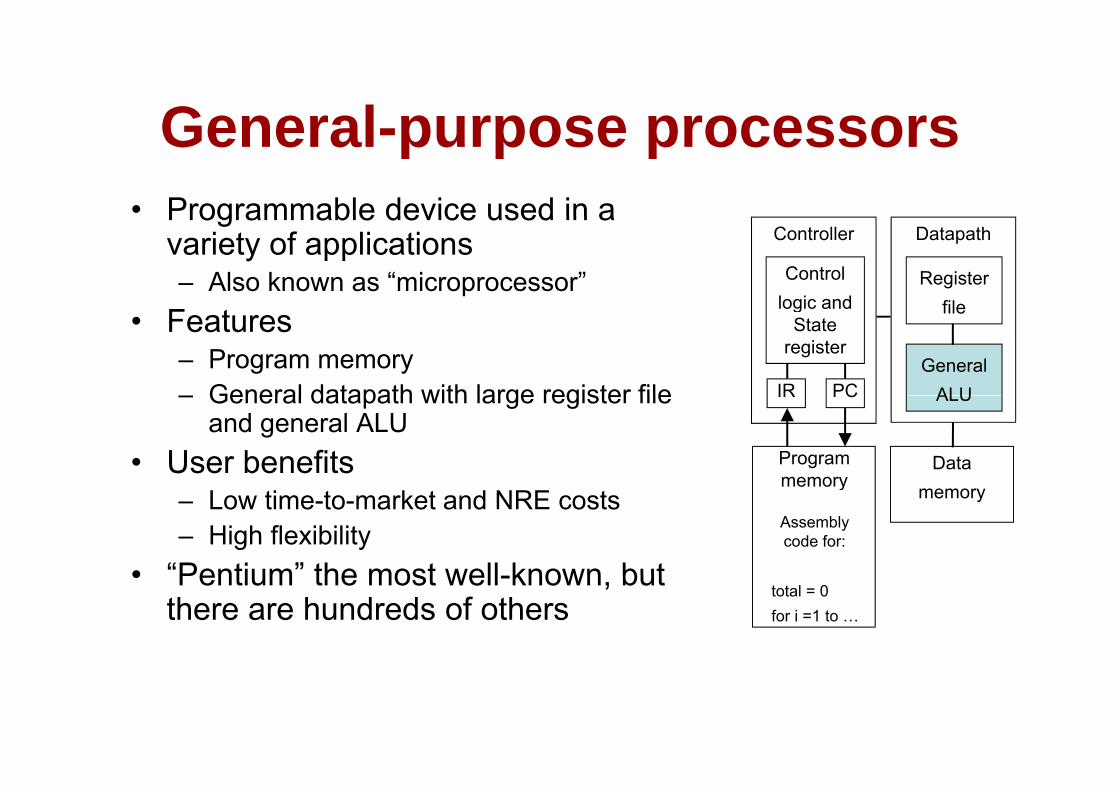
General purpose processorsGeneral-purpose processors• Programmable device used in aProgrammable device used in a
variety of applications– Also known as “microprocessor” Register
file
DatapathController
Control logic and
• Features– Program memory– General datapath with large register file IR PC
file
GeneralALU
logic and State
register
– General datapath with large register file and general ALU
• User benefits
IR PC ALU
Program memory
Data
– Low time-to-market and NRE costs– High flexibility
• “Pentium” the most well known but
memory
Assembly code for:
memory
• Pentium the most well-known, but there are hundreds of others
total = 0for i =1 to …

Single purpose processorsSingle-purpose processorsDigital circuit designed to execute• Digital circuit designed to execute exactly one program– a k a coprocessor accelerator or
DatapathController
Control logic
index
a.k.a. coprocessor, accelerator or peripheral
– JPEG codecState
register
total
+
• Features– Contains only the components needed to
execute a single program
Datamemory
execute a single program– No program memory
• BenefitsBenefits– Fast– Low power– Small size
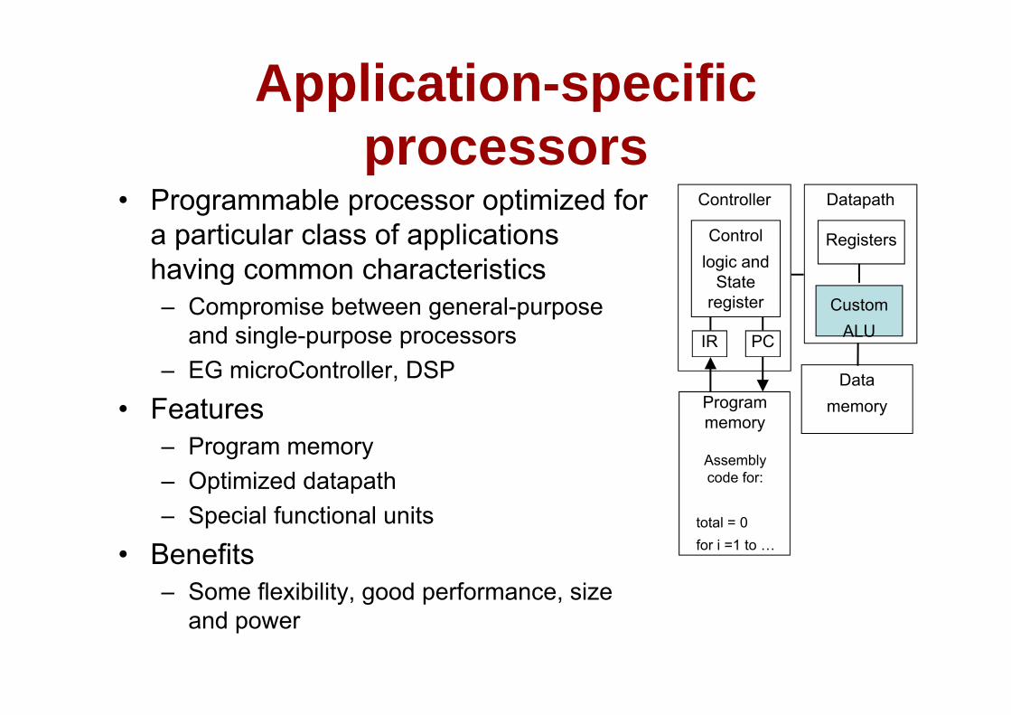
Application-specific processors
Programmable processor optimized for D t thC t ll• Programmable processor optimized for a particular class of applications having common characteristics
Registers
DatapathController
Control logic and
St thaving common characteristics– Compromise between general-purpose
and single-purpose processors IR PC
CustomALU
State register
– EG microController, DSP
• FeaturesP
Program memory
Datamemory
– Program memory– Optimized datapath– Special functional units
Assembly code for:
total 0Special functional units
• Benefits– Some flexibility, good performance, size
total = 0for i =1 to …
y, g p ,and power
IC technologyIC technologyTh t f IC t h l i• Three types of IC technologies– Full-custom/VLSI– Semi-custom ASIC (Application Specific
Integrated Circuitteg ated C cu t– PLD (Programmable Logic Device)
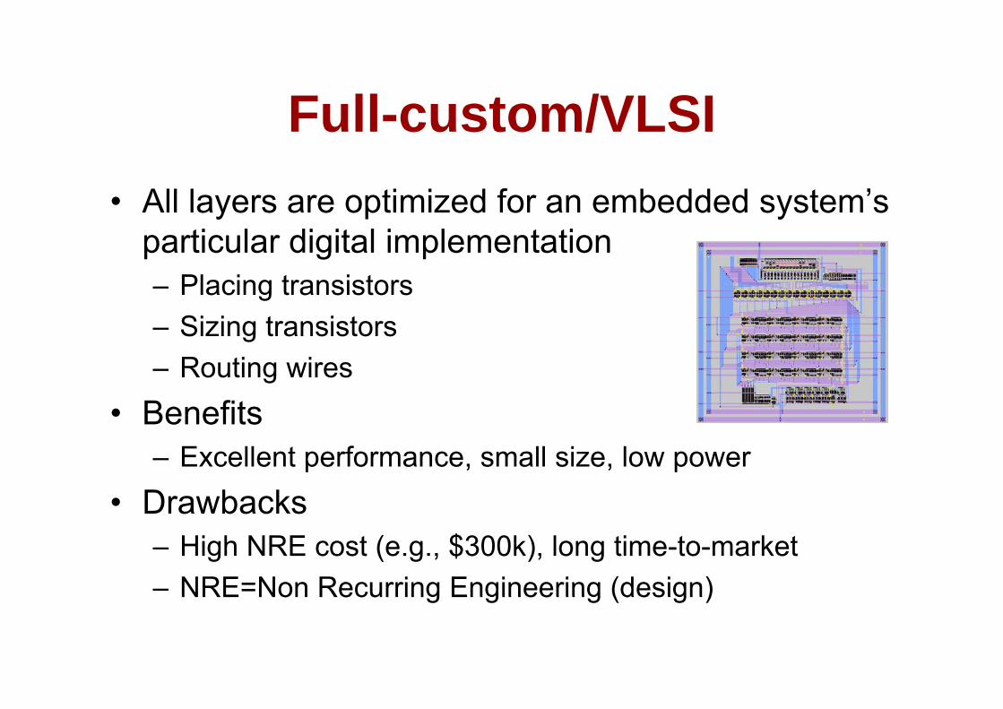
Full custom/VLSIFull-custom/VLSIAll l ti i d f b dd d t ’• All layers are optimized for an embedded system’s particular digital implementation– Placing transistors– Sizing transistors– Routing wires
• Benefits– Excellent performance, small size, low power
• Drawbacks– High NRE cost (e.g., $300k), long time-to-market– NRE=Non Recurring Engineering (design)NRE Non Recurring Engineering (design)
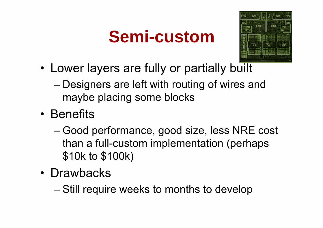
Semi customSemi-custom
• Lower layers are fully or partially built– Designers are left with routing of wires and g g
maybe placing some blocks• Benefits• Benefits
– Good performance, good size, less NRE cost th f ll t i l t ti ( hthan a full-custom implementation (perhaps $10k to $100k)
• Drawbacks– Still require weeks to months to developStill require weeks to months to develop
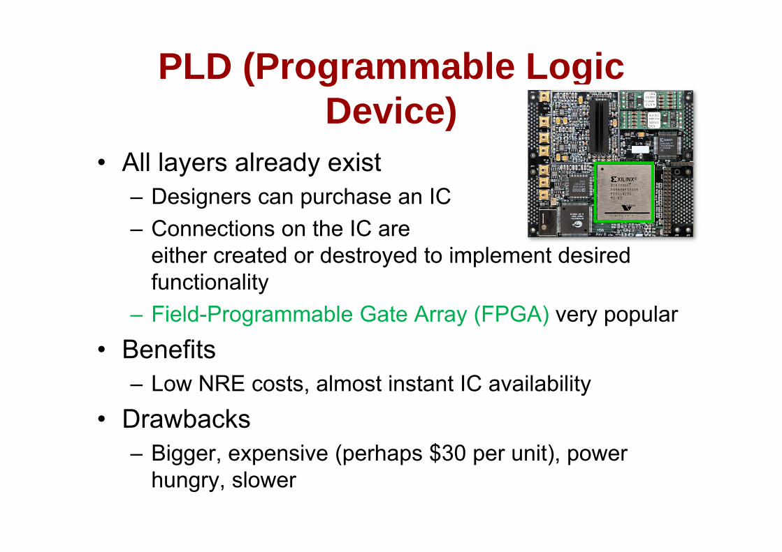
PLD (Programmable Logic Device)
• All layers already exist– Designers can purchase an IC– Connections on the IC are
either created or destroyed to implement desired f ti litfunctionality
– Field-Programmable Gate Array (FPGA) very popular• Benefits
– Low NRE costs, almost instant IC availability• Drawbacks
– Bigger, expensive (perhaps $30 per unit), power gg p (p p p ) phungry, slower
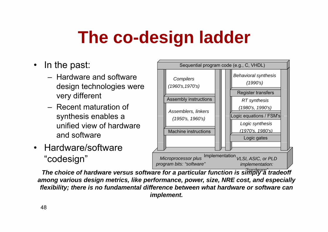
The co design ladderThe co-design ladderIn the past: S ( C )• In the past:– Hardware and software
design technologies were Compilers
(1960's,1970's)
Behavioral synthesis(1990's)
Sequential program code (e.g., C, VHDL)
g gvery different
– Recent maturation of synthesis enables a
Assembly instructionsRegister transfers
Assemblers, linkers
RT synthesis(1980's, 1990's)
Logic equations / FSM'ssynthesis enables a unified view of hardware and software Machine instructions
(1950's, 1960's)Logic synthesis(1970's, 1980's)
Logic gates
Logic equations / FSM s
• Hardware/software “codesign” ImplementationMicroprocessor plus
program bits: “software”VLSI, ASIC, or PLD
implementation: “h d ”“hardware”The choice of hardware versus software for a particular function is simply a tradeoff
among various design metrics, like performance, power, size, NRE cost, and especially flexibility; there is no fundamental difference between what hardware or software can
implement
48
implement.
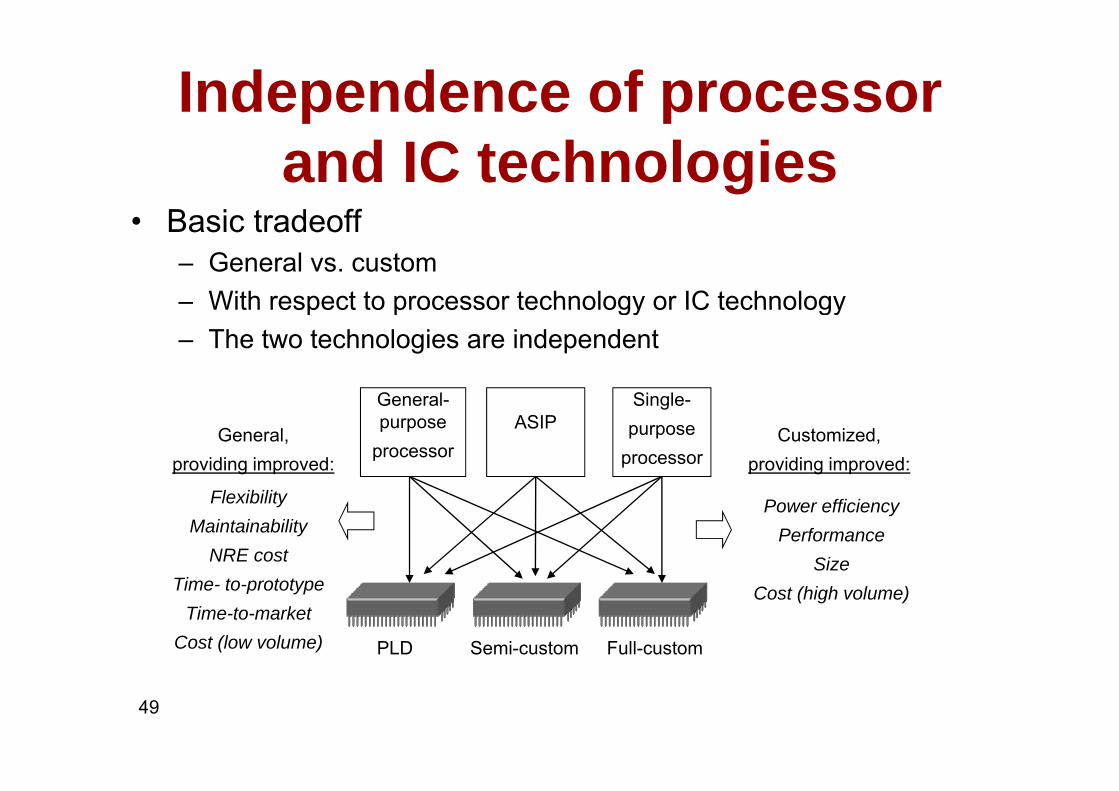
Independence of processor and IC technologies
Basic tradeoff• Basic tradeoff– General vs. custom– With respect to processor technology or IC technologyWith respect to processor technology or IC technology– The two technologies are independent
G l Si lGeneral-purpose
processorASIP
Single-purpose
processorGeneral,
providing improved:Customized,
providing improved:
Power efficiencyPerformance
Size
FlexibilityMaintainability
NRE cost
Semi-customPLD Full-custom
Cost (high volume)Time- to-prototypeTime-to-market
Cost (low volume)
49

NXTNXT
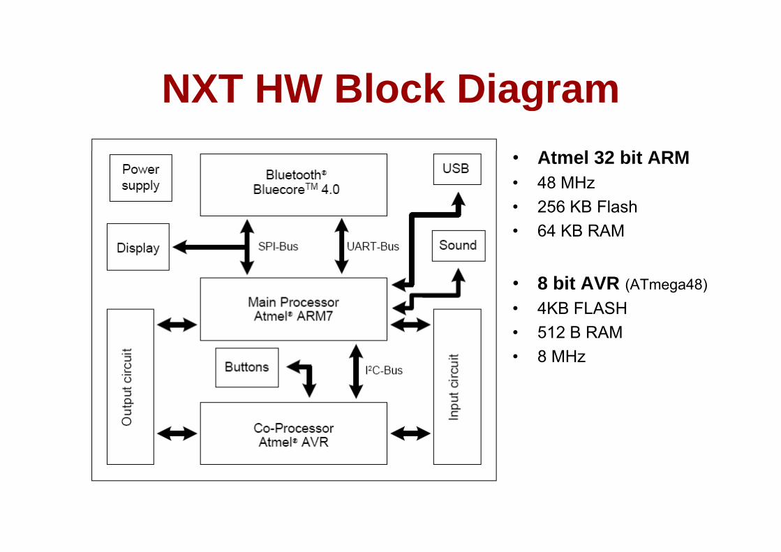
NXT HW Block DiagramNXT HW Block DiagramA l 32 bi ARM• Atmel 32 bit ARM
• 48 MHz• 256 KB Flash• 64 KB RAM
• 8 bit AVR (ATmega48)• 4KB FLASH• 512 B RAM• 8 MHz
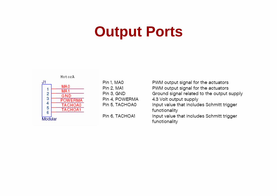
Output PortsOutput Ports

Pulse width modulatorPulse width modulator• Generates pulses with
clk
pwm_o
Generates pulses with specific high/low times
• Duty cycle: % time high
25% duty cycle – average pwm_o is 1.25V
pwm o
– Square wave: 50% duty cycle
• Common use: control
clk
pwm_o
50% duty cycle – average pwm o is 2 5V
average voltage to electric device– Simpler than DC-DC 50% duty cycle average pwm_o is 2.5V.
pwm_o
Simpler than DC DC converter or digital-analog converter
– DC motor speed dimmer clk
75% duty cycle – average pwm_o is 3.75V.
– DC motor speed, dimmer lights
• Another use: encode d i
53
commands, receiver uses timer to decode Period ~16 clock tics
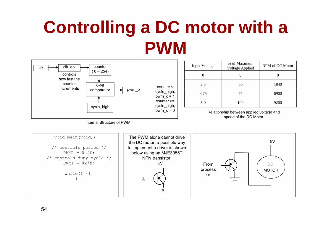
Controlling a DC motor with a PWM
% of Maximumclk_div counter
( 0 – 254)
8-bit comparator
controls how fast the
counter increments counter <
l hi hpwm o
clk Input Voltage % of MaximumVoltage Applied RPM of DC Motor
0 0 0
2.5 50 1840
cycle_high
comparator cycle_high,pwm_o = 1counter >= cycle_high, pwm_o = 0
pwm_o3.75 75 6900
5.0 100 9200
Relationship between applied voltage and speed of the DC Motor
void main(void){ The PWM alone cannot drive the DC motor, a possible way
Internal Structure of PWMspeed of the DC Motor
5V/* controls period */
PWMP = 0xff; /* controls duty cycle */
PWM1 = 0x7f;
the DC motor, a possible way to implement a driver is shown
below using an MJE3055T NPN transistor.
5V DC MOTOR
From process
while(1){};}
B
A
MOTORprocessor
54
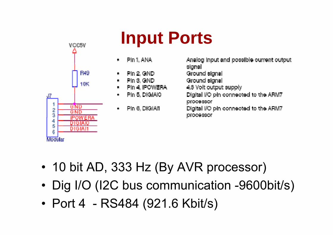
Input PortsInput Ports
• 10 bit AD, 333 Hz (By AVR processor)10 bit AD, 333 Hz (By AVR processor)• Dig I/O (I2C bus communication -9600bit/s)• Port 4 - RS484 (921.6 Kbit/s)
Input SensorsInput Sensors
• Passive– Light, Touch, Sound, Tempg , , , p
• DigitalUlt S i– UltraSonic
– I2C • => Port configuration depends on sensor

Serial protocols: I2CSerial protocols: I2CI2C (Inter IC)• I2C (Inter-IC)– Two-wire serial bus protocol developed by Philips Semiconductors
nearly 20 years agoy y g– Enables peripheral ICs to communicate using simple
communication hardwareD t t f t t 100 kbit / d 7 bit dd i ibl– Data transfer rates up to 100 kbits/s and 7-bit addressing possible in normal mode
– 3.4 Mbits/s and 10-bit addressing in fast-modeg– Common devices capable of interfacing to I2C bus:
• EPROMS, Flash, and some RAM memory, real-time clocks, watchdog timers and microcontrollerstimers, and microcontrollers
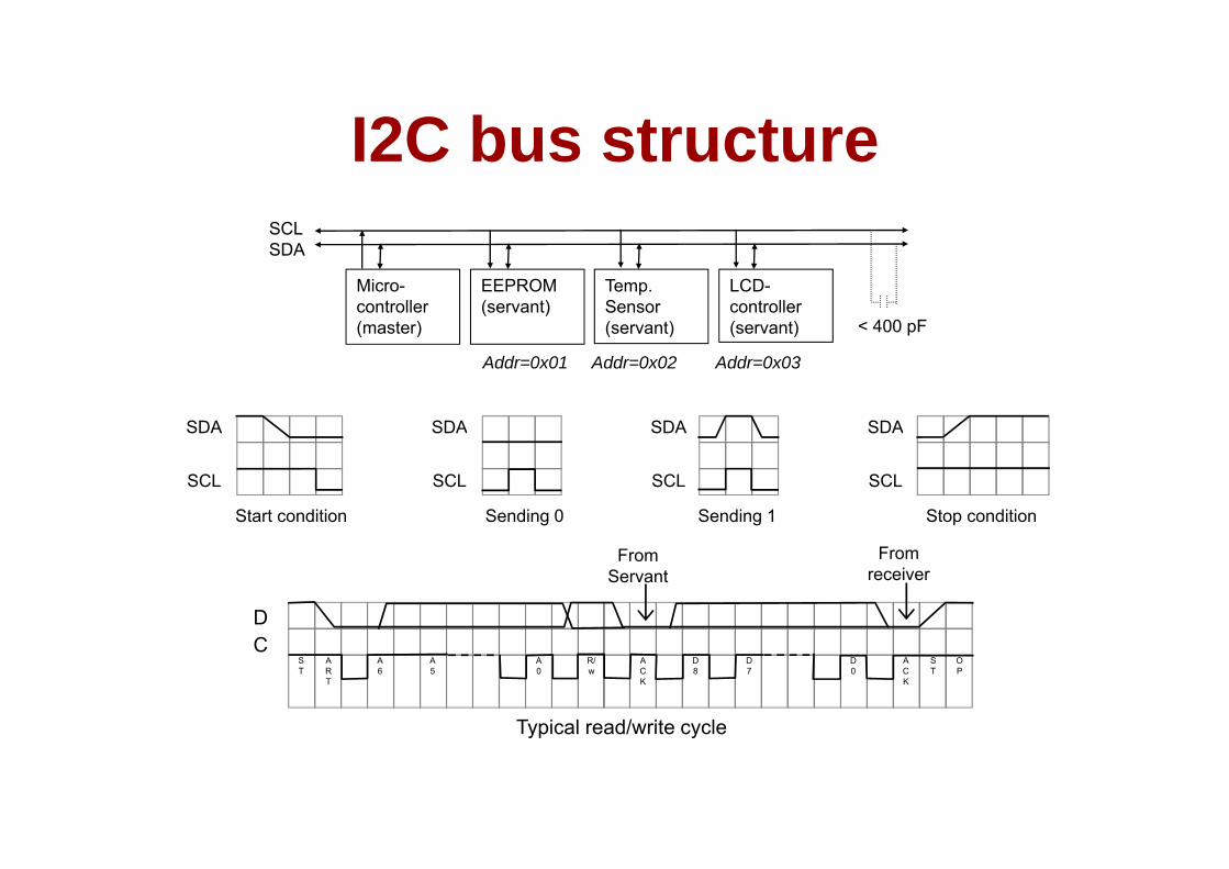
I2C bus structureI2C bus structureSCLSDA
Micro-controller(master)
EEPROM(servant)
Temp. Sensor(servant)
LCD-controller(servant) < 400 pF( ) ( ) ( )
Addr=0x01 Addr=0x02 Addr=0x03
SDA SDA SDA SDA
SCL SCL SCL SCL
Start condition Sending 0 Sending 1 Stop condition
D
From Servant
From receiver
CST
ART
A6
A5
A0
R/w
ACK
D8
D7
D0
ACK
ST
OP
Typical read/write cycleTypical read/write cycle
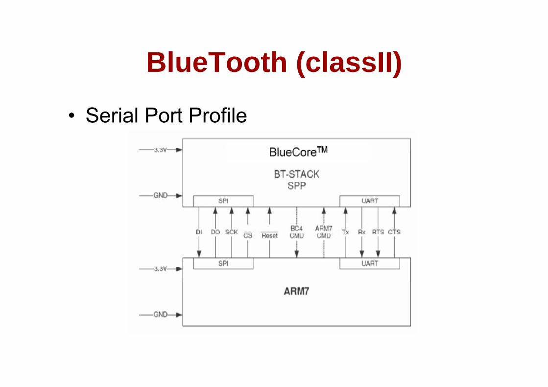
BlueTooth (classII)BlueTooth (classII)
• Serial Port Profile
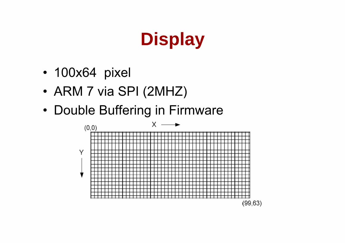
DisplayDisplay
• 100x64 pixel• ARM 7 via SPI (2MHZ)ARM 7 via SPI (2MHZ)• Double Buffering in Firmware
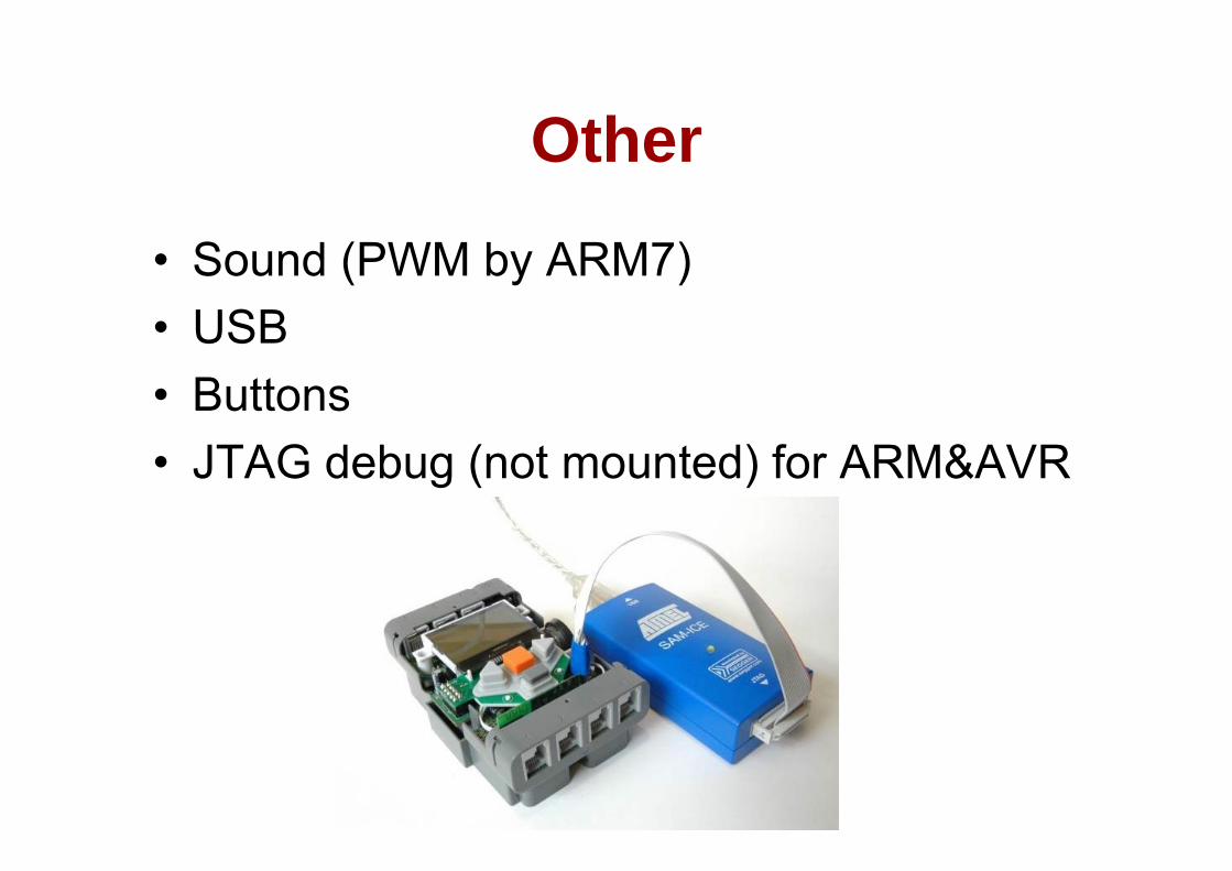
OtherOther
• Sound (PWM by ARM7)• USBUSB• Buttons • JTAG debug (not mounted) for ARM&AVR

AVR < > ARMAVR <-> ARM
• AVR– Power management– PWM modulation for engines– AD conversion for analogue input portsg p p– Buttons
• Exchanged info via internal i2c every 2 ms• Exchanged info via internal i2c every 2 msARM to AVR AVR to ARM

B i S liBasic Sampling
Brian [email protected]
Based on Chapter 3:"The Scientist and Engineer's Guide to Digital SignalThe Scientist and Engineer s Guide to Digital Signal
Processing, copyright ©1997-1998 by Steven W. Smith. For more information visit the book's website at:
www.DSPguide.com"
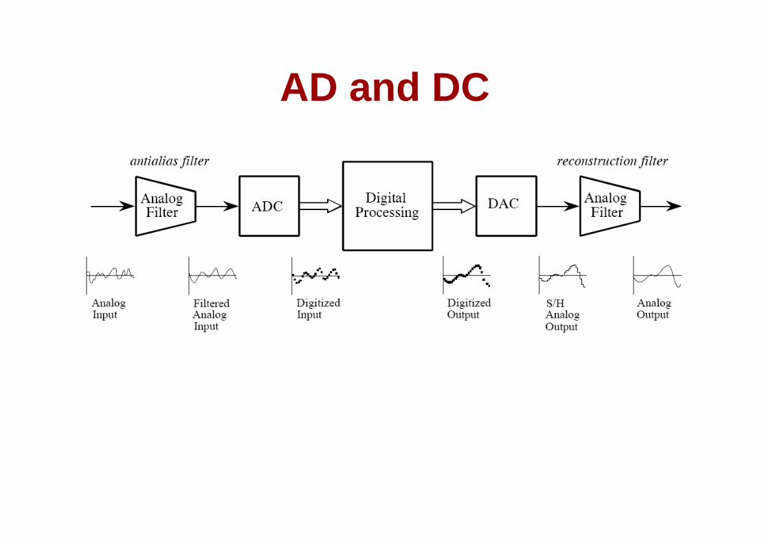
AD and DCAD and DC

AD ConversionAD Conversion
Quantization: number of levelsSampling Frequency: samples/secp g q y p
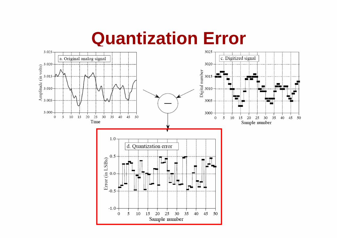
Quantization ErrorQuantization Error
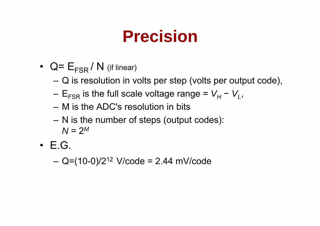
PrecisionPrecision• Q= EFSR / N (if linear)
– Q is resolution in volts per step (volts per output code),– EFSR is the full scale voltage range = VH − VL,– M is the ADC's resolution in bits– N is the number of steps (output codes):
N = 2M
• E.G.– Q=(10-0)/212 V/code = 2.44 mV/codeQ ( )
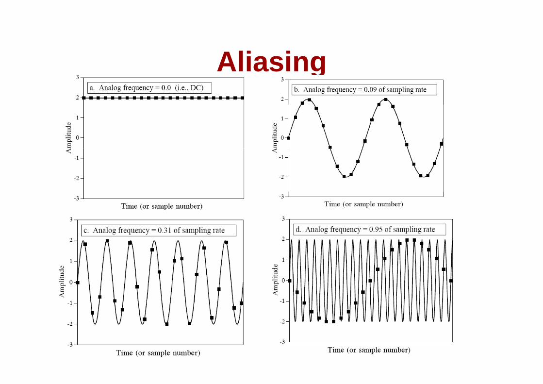
AliasingAliasing
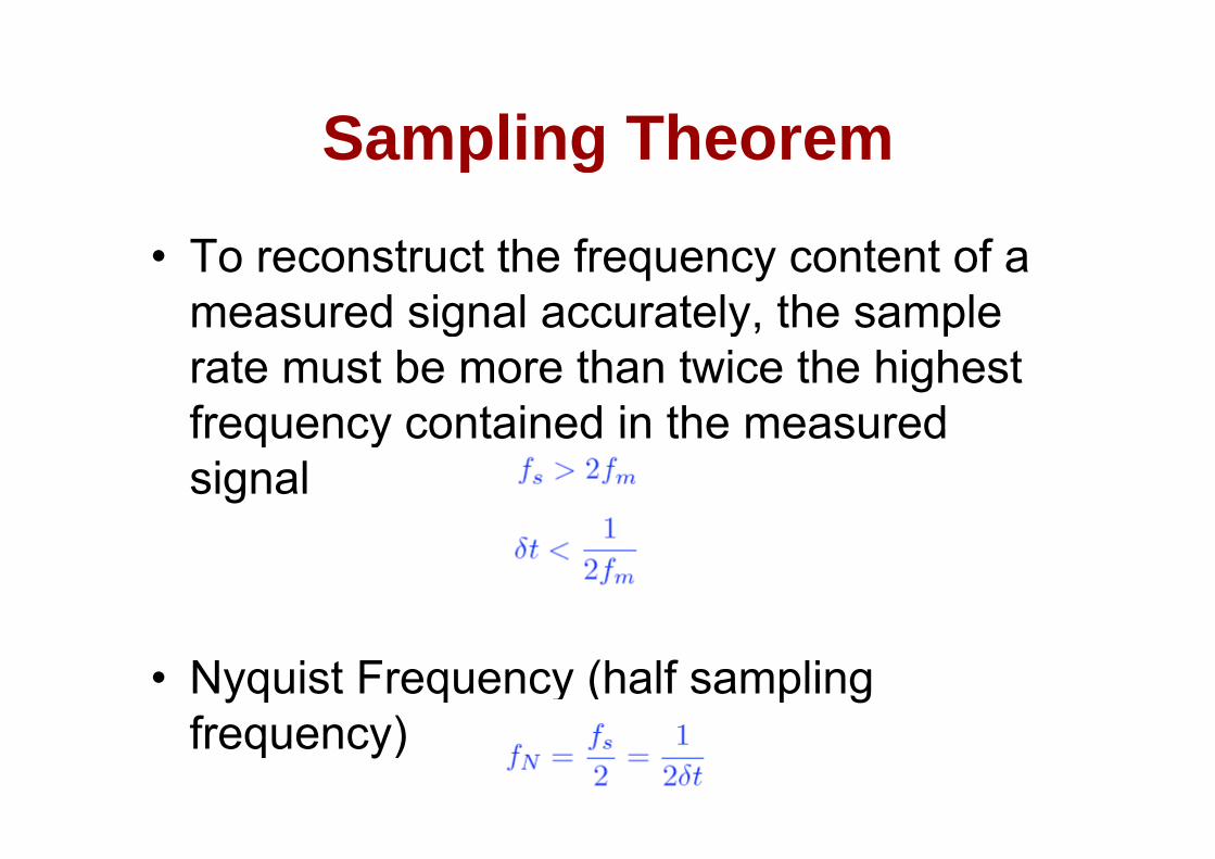
Sampling TheoremSampling Theorem
• To reconstruct the frequency content of a measured signal accurately, the sample g y, prate must be more than twice the highest frequency contained in the measuredfrequency contained in the measured signal
• Nyquist Frequency (half sampling f )frequency)
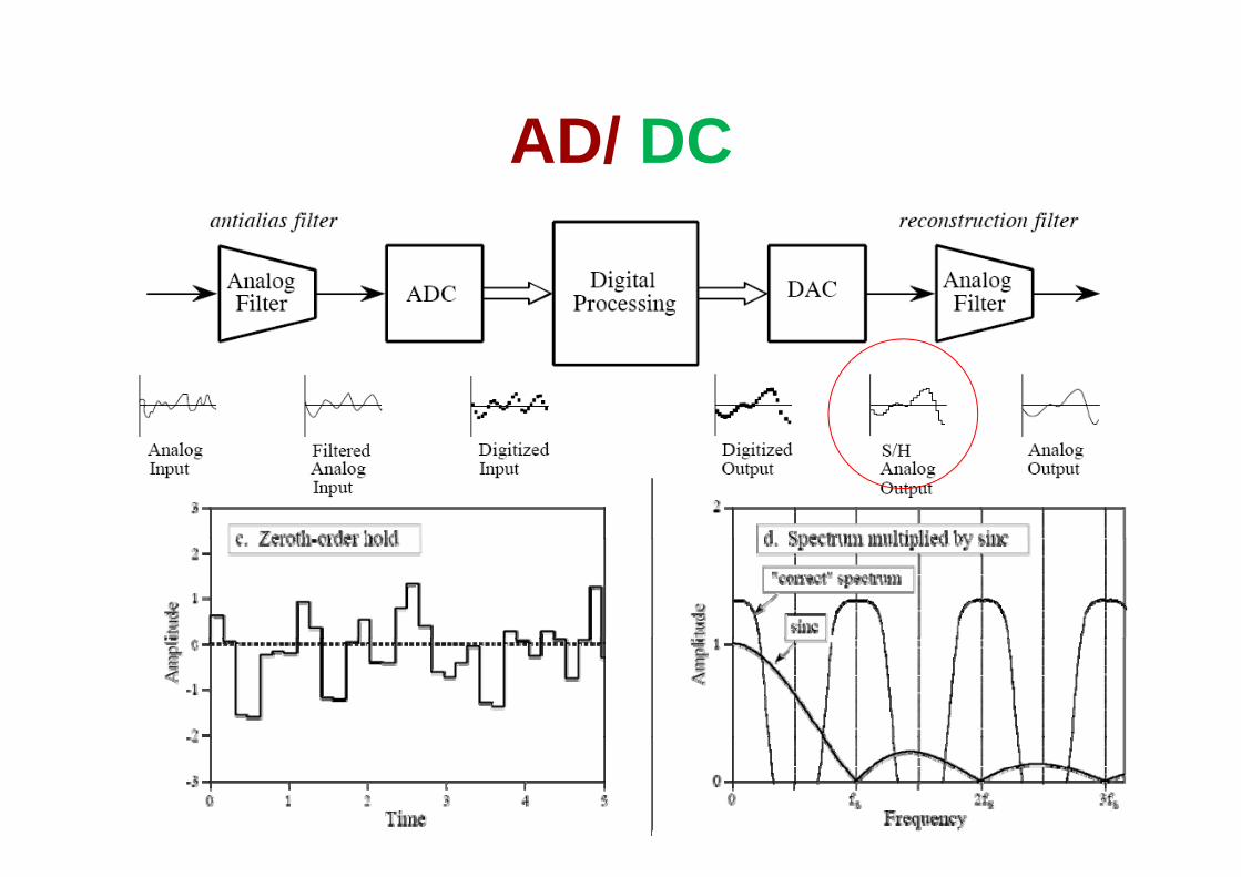
AD/ DCAD/ DC

Low pass filtersLow-pass filters
• Sharpness• Attenuation• Attenuation• Ripple / Over-undershoot