Embed Size (px)
Citation preview
NXP Secure Smart Card Controller P60D144/080MVA Security Target Lite
Rev. 1.7 — 19-Feb-2013
BSI-DSZ-CC-0840
Evaluation documentation
PUBLIC
Document information
Info Content
Keywords CC, Security Target Lite, P60D144/080MVA
Abstract Security Target Lite of the NXP Secure Smart Card Controller
P60D144/080MVA, which is developed and provided by NXP
Semiconductors, Business Unit Identification according to the Common
Criteria for Information Technology Security Evaluation Version 3.1 at
Evaluation Assurance Level 5 augmented.
NXP Semiconductors P60D144/080MVA Security Target Lite
All information provided in this document is subject to legal disclaimers. © NXP B.V. 2013. All rights reserved.
Evaluation documentation PUBLIC
Rev. 1.7 — 19-Feb-2013 2 of 101
Contact information
For additional information, please visit: http://www.nxp.com
For sales office addresses, please send an email to: [email protected]
Revision history
Rev Date Description
Rev. 1.7 19-Feb-2013 Derived from P60D144/080MVA Security Target
Latest version is: Rev. 1.7 (19-Feb-2013)

NXP Semiconductors P60D144/080MVA Security Target Lite
All information provided in this document is subject to legal disclaimers. © NXP B.V. 2013. All rights reserved.
Evaluation documentation PUBLIC
Rev. 1.7 — 19-Feb-2013 3 of 101
1. ST Introduction
This chapter is divided into the following sections: “ST Reference”, “TOE Reference”,
“TOE Overview” and “TOE Description”.
1.1 ST Reference
“NXP Secure Smart Card Controller P60D144/080MVA Security Target Lite, NXP
Semiconductors, Business Unit Identification, Rev. 1.7, 19-Feb-2013”
1.2 TOE Reference
The TOE is named NXP Secure Smart Card Controller P60D144/080MVA including IC
Dedicated Software with MIFARE Plus MF1PLUSx0.
1.3 TOE Overview
1.3.1 Usage and major security functionality of the TOE
The TOE is the IC hardware platform NXP Secure Smart Card Controller
P60D144/080MVA with IC Dedicated Software and documentation describing the
Instruction Set and the usage. The TOE is delivered as with a customer specific Security
IC Embedded Software.
The IC hardware platform NXP Secure Smart Card Controller P60D144/080MVA is a
microcontroller incorporating a central processing unit, memories accessible via a Memory
Management Unit, cryptographic coprocessors, other security components and two
communication interfaces. The central processing unit supports a 32-/24-/16-/8-bit
instruction set optimized for smart card applications, which is a super set of the 80C51
family instruction set. The first and in some cases the second byte of an instruction are
used for operation encoding. On-chip memories are ROM, RAM and EEPROM. The non-
volatile EEPROM can be used as data or program memory. It consists of high reliable
memory cells, which guarantee data integrity. The EEPROM is optimized for applications
requiring reliable non-volatile data storage for data and program code. Dedicated security
functionality protects the contents of all memories.
The IC Dedicated Software comprises IC Dedicated Test Software for test purposes and
IC Dedicated Support Software. The IC Dedicated Support Software consists of Boot-
ROM Software controlling the boot process of the hardware platform and Firmware
Operating System (FOS) which can be called by the Security IC Embedded Software. The
Firmware Operating System provides an interface for programming of the internal
EEPROM memory, which is mandatory for use by the Security IC Embedded Software
when programming the EEPROM memory. Furthermore FOS provides an interface for the
Post Delivery Configuration functionality. OS Emulation MIFARE Plus MF1PLUSx0 is
included in the FOS and is therefore part of the TOE as described in this document. The
MIFARE Plus MF1PLUSx0 provides a set of functions used to manage the data stored in
the non-volatile EEPROM memory owned by MIFARE Plus MF1PLUSx0.
NXP has developed MIFARE Plus MF1PLUSx0 to be used with Proximity Coupling
Devices (PCDs) according to ISO14443 Type A. The communication protocol complies to
part ISO 14443-3 and 14443-4. The MIFARE Plus MF1PLUSx0 is primarily designed for
secure contact-less transport applications and related loyalty programs as well as access
management systems. It fully complies with the requirements for fast and highly secure
data transmission, flexible data storage and interoperability with existing infrastructures.
NXP Semiconductors P60D144/080MVA Security Target Lite
All information provided in this document is subject to legal disclaimers. © NXP B.V. 2013. All rights reserved.
Evaluation documentation PUBLIC
Rev. 1.7 — 19-Feb-2013 4 of 101
The TOE supports the virtual card architecture by providing a selection mechanism for
virtual cards. This allows using the TOE in a complex environment where multiple virtual
cards are stored in one physical object, however the TOE does support only one virtual
card.
The documentation includes a Data Sheet, a description of the Instruction Set, a Guidance
Document, a functional specification for the functionality provided by the MIFARE Plus
MF1PLUSx0 and a document describing the delivery of the product. This documentation
comprises a description of the architecture, the secure configuration and usage of the IC
hardware platform and the IC Dedicated Software by the Security IC Embedded Software.
The security functionality of the TOE is designed to act as an integral part of a complete
security system in order to strengthen the design as a whole. Several security
mechanisms are completely implemented in and controlled by the TOE. Other security
mechanisms allow for configuration or even require handling of exceptions by the Security
IC Embedded Software. The different CPU modes and the Memory Management Unit
support the implementation of multi-application projects using the NXP Secure Smart Card
Controller P60D144/080MVA.
A Security IC must provide high security in particular when being used in the banking and
finance market, in electronic commerce or in governmental applications because the TOE
is intended to be used in a potential insecure environment. Hence the TOE shall maintain
the integrity and the confidentiality of code and data stored in its memories,
the different CPU modes with the related capabilities for configuration and memory
access and
the integrity, the correct operation and the confidentiality of security functionality
provided by the TOE.
This is ensured by the construction of the TOE and its security functionality.
NXP Secure Smart Card Controller P60D144/080MVA basically provides a hardware
platform for an implementation of a smart card application with
functionality to calculate the Data Encryption Standard (Triple-DES) with up to three
keys,
functionality to calculate the Advanced Encryption Standard (AES) with different key
lengths,
support for large integer arithmetic operations like multiplication, addition and logical
operations, which are suitable for public key cryptography and elliptic curve
cryptography,
a True Random Number Generator,
memory management control,
cyclic redundancy check (CRC) calculation,
ISO/IEC 7816 contact interface with UART,
Contactless interface supporting MIFARE Plus MF1PLUSx0 and ISO/IEC 14443 A.
In addition, several security mechanisms are implemented to ensure proper operation as
well as integrity and confidentiality of stored data. For example, this includes security
mechanisms for memory protection and security exceptions as well as sensors, which
allow operation under specified conditions only. Memory encryption is used for memory
protection and chip shielding is added to the chip.
NXP Semiconductors P60D144/080MVA Security Target Lite
All information provided in this document is subject to legal disclaimers. © NXP B.V. 2013. All rights reserved.
Evaluation documentation PUBLIC
Rev. 1.7 — 19-Feb-2013 5 of 101
Note: Large integer arithmetic operations are intended to be used for calculation of
asymmetric cryptographic algorithms. Any asymmetric cryptographic
algorithm utilizing the support for large integer arithmetic operations has to
be implemented in the Security IC Embedded Software. Thus, the support
for large integer arithmetic operations itself does not provide security
functionality like cryptographic support. The Security IC Embedded Software
implementing an asymmetric cryptographic algorithm is not included in this
evaluation. Nevertheless the support for large integer arithmetic operations
is part of the Security IC and therefore a security relevant component of the
TOE, that must resist to the attacks mentioned in this Security Target and
that must operate correctly as specified in the data sheet. The same scope
of evaluation is applied to the CRC calculation.
1.3.2 TOE type
The TOE NXP Secure Smart Card Controller P60D144/080MVA is provided as IC
hardware platform for various operating systems and applications with high security
requirements.
1.3.3 Required non-TOE hardware/software/firmware
None
1.4 TOE Description
1.4.1 Physical Scope of TOE
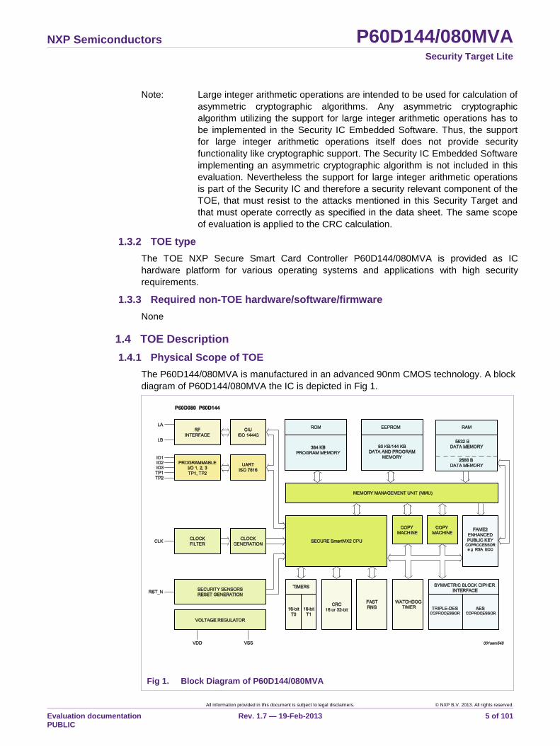
The P60D144/080MVA is manufactured in an advanced 90nm CMOS technology. A block
diagram of P60D144/080MVA the IC is depicted in Fig 1.
Fig 1. Block Diagram of P60D144/080MVA
NXP Semiconductors P60D144/080MVA Security Target Lite
All information provided in this document is subject to legal disclaimers. © NXP B.V. 2013. All rights reserved.
Evaluation documentation PUBLIC
Rev. 1.7 — 19-Feb-2013 6 of 101
The TOE consists of the IC hardware platform and IC Dedicated Software as composed of
IC Dedicated Test Software and IC Dedicated Support Software. All other software is
called Security IC Embedded Software. The Security IC Embedded Software is not part of
the TOE. The TOE components are listed in Table 1.
1.4.1.1 TOE components
Note: P60D144/080MVA is part of the SmartMX2 family and reuses documentation of the
Security IC. These documents miss the major configuration identifier „M‟, because „M‟
describes an additional software feature implemented on the Security IC, whereas the
Security IC implementation stays as is.
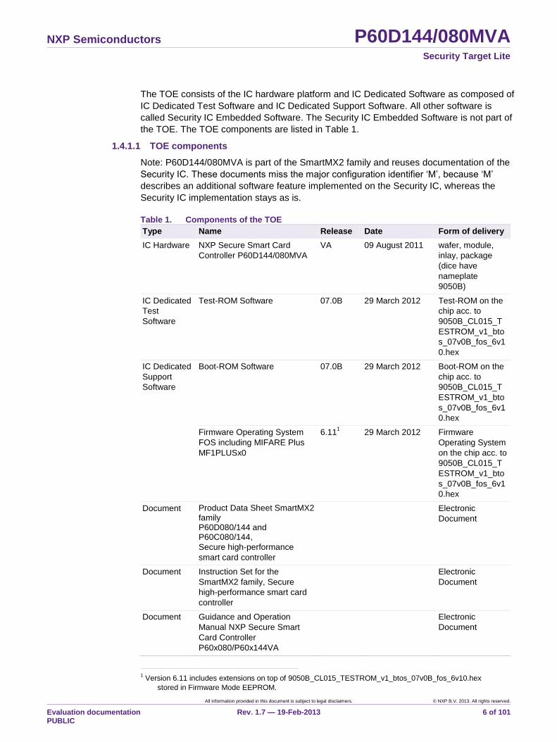
Table 1. Components of the TOE
Type Name Release Date Form of delivery
IC Hardware NXP Secure Smart Card
Controller P60D144/080MVA
VA 09 August 2011 wafer, module,
inlay, package
(dice have
nameplate
9050B)
IC Dedicated
Test
Software
Test-ROM Software 07.0B 29 March 2012 Test-ROM on the
chip acc. to
9050B_CL015_T
ESTROM_v1_bto
s_07v0B_fos_6v1
0.hex
IC Dedicated
Support
Software
Boot-ROM Software 07.0B 29 March 2012 Boot-ROM on the
chip acc. to
9050B_CL015_T
ESTROM_v1_bto
s_07v0B_fos_6v1
0.hex
Firmware Operating System
FOS including MIFARE Plus
MF1PLUSx0
6.111 29 March 2012 Firmware
Operating System
on the chip acc. to
9050B_CL015_T
ESTROM_v1_bto
s_07v0B_fos_6v1
0.hex
Document Product Data Sheet SmartMX2 family P60D080/144 and P60C080/144,
Secure high-performance
smart card controller
Electronic
Document
Document Instruction Set for the
SmartMX2 family, Secure
high-performance smart card
controller
Electronic
Document
Document Guidance and Operation
Manual NXP Secure Smart
Card Controller
P60x080/P60x144VA
Electronic
Document
1 Version 6.11 includes extensions on top of 9050B_CL015_TESTROM_v1_btos_07v0B_fos_6v10.hex
stored in Firmware Mode EEPROM.
NXP Semiconductors P60D144/080MVA Security Target Lite
All information provided in this document is subject to legal disclaimers. © NXP B.V. 2013. All rights reserved.
Evaluation documentation PUBLIC
Rev. 1.7 — 19-Feb-2013 7 of 101
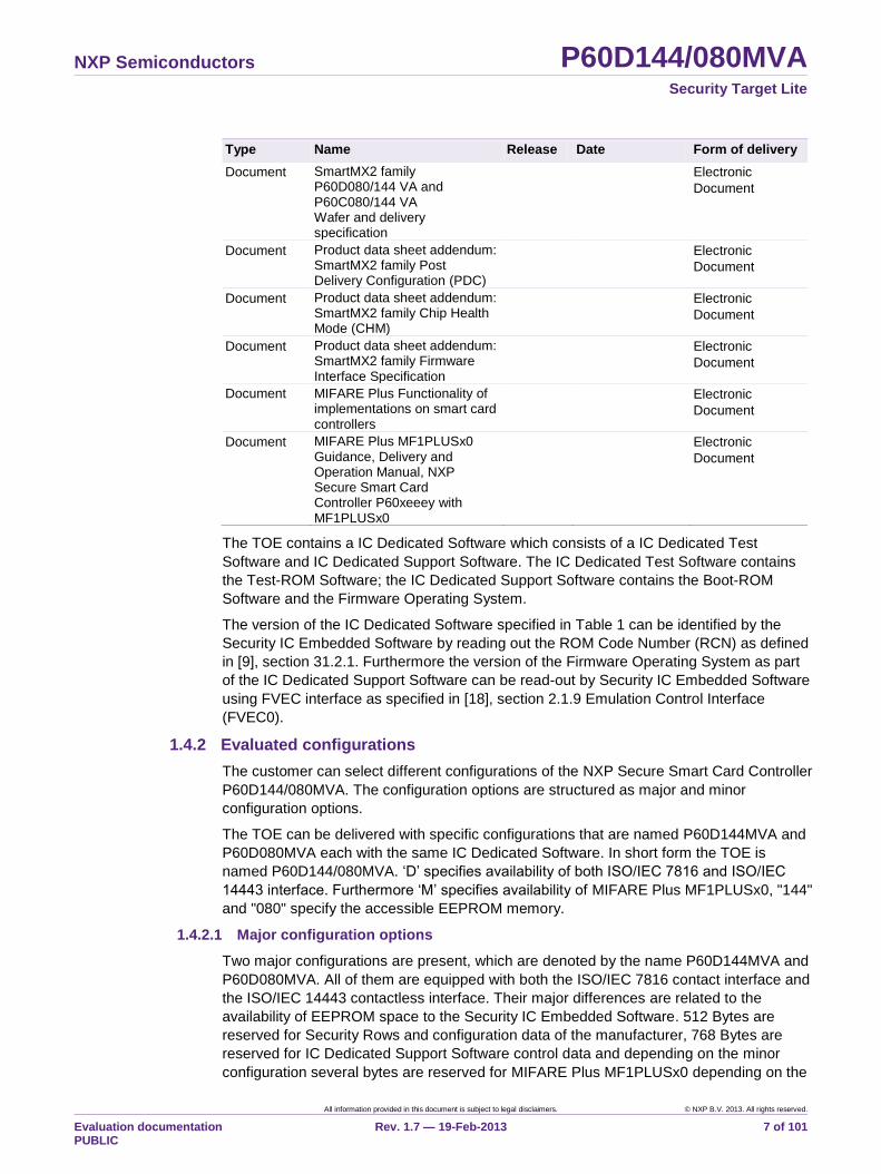
Type Name Release Date Form of delivery
Document SmartMX2 family P60D080/144 VA and P60C080/144 VA Wafer and delivery specification
Electronic
Document
Document Product data sheet addendum: SmartMX2 family Post Delivery Configuration (PDC)
Electronic
Document
Document Product data sheet addendum: SmartMX2 family Chip Health Mode (CHM)
Electronic
Document
Document Product data sheet addendum: SmartMX2 family Firmware Interface Specification
Electronic
Document
Document MIFARE Plus Functionality of implementations on smart card controllers
Electronic
Document
Document MIFARE Plus MF1PLUSx0 Guidance, Delivery and Operation Manual, NXP Secure Smart Card Controller P60xeeey with MF1PLUSx0
Electronic
Document
The TOE contains a IC Dedicated Software which consists of a IC Dedicated Test
Software and IC Dedicated Support Software. The IC Dedicated Test Software contains
the Test-ROM Software; the IC Dedicated Support Software contains the Boot-ROM
Software and the Firmware Operating System.
The version of the IC Dedicated Software specified in Table 1 can be identified by the
Security IC Embedded Software by reading out the ROM Code Number (RCN) as defined
in [9], section 31.2.1. Furthermore the version of the Firmware Operating System as part
of the IC Dedicated Support Software can be read-out by Security IC Embedded Software
using FVEC interface as specified in [18], section 2.1.9 Emulation Control Interface
(FVEC0).
1.4.2 Evaluated configurations
The customer can select different configurations of the NXP Secure Smart Card Controller
P60D144/080MVA. The configuration options are structured as major and minor
configuration options.
The TOE can be delivered with specific configurations that are named P60D144MVA and
P60D080MVA each with the same IC Dedicated Software. In short form the TOE is
named P60D144/080MVA. „D‟ specifies availability of both ISO/IEC 7816 and ISO/IEC
14443 interface. Furthermore „M‟ specifies availability of MIFARE Plus MF1PLUSx0, "144"
and "080" specify the accessible EEPROM memory.
1.4.2.1 Major configuration options
Two major configurations are present, which are denoted by the name P60D144MVA and
P60D080MVA. All of them are equipped with both the ISO/IEC 7816 contact interface and
the ISO/IEC 14443 contactless interface. Their major differences are related to the
availability of EEPROM space to the Security IC Embedded Software. 512 Bytes are
reserved for Security Rows and configuration data of the manufacturer, 768 Bytes are
reserved for IC Dedicated Support Software control data and depending on the minor
configuration several bytes are reserved for MIFARE Plus MF1PLUSx0 depending on the
NXP Semiconductors P60D144/080MVA Security Target Lite
All information provided in this document is subject to legal disclaimers. © NXP B.V. 2013. All rights reserved.
Evaluation documentation PUBLIC
Rev. 1.7 — 19-Feb-2013 8 of 101
EEPROM size of MIFARE Plus MF1PLUSx0. Available EEPROM sizes for MIFARE Plus
MF1PLUSx0 are 4kByte (M4) and 2kByte (M2).
Each major configuration is provided with several minor configuration options, which are
introduced in Section 1.4.2.2. Each major configuration also provides customers with
several options for reconfiguration (Post Delivery Configuration), which are described in
Section 1.4.2.3 in detail.
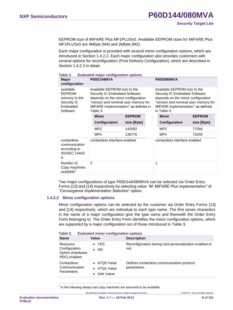
Table 2. Evaluated major configuration options
Major
configuration
P60D144MVA P60D080MVA
available
EEPROM
memory to the
Security IC
Embedded
Software
Available EEPROM size to the
Security IC Embedded Software
depends on the minor configuration
“version and nominal user memory for
MIFARE implementation” as defined in
Table 3:
Minor
Configuration
EEPROM
size [Byte]
MP2 142592
MP4 139776
Available EEPROM size to the
Security IC Embedded Software
depends on the minor configuration
“version and nominal user memory for
MIFARE implementation” as defined
in Table 3:
Minor
Configuration
EEPROM
size [Byte]
MP2 77056
MP4 74240
contactless
communication
according to
ISO/IEC 14443
A
contactless interface enabled contactless interface enabled
Number of
Copy machines
available2
2 1
Two major configurations of type P60D144/080MVA can be selected via Order Entry Forms [13] and [14] respectively by selecting value “M: MIFARE Plus implementation” of “Convergence Implementation Selection” option.
1.4.2.2 Minor configuration options
Minor configuration options can be selected by the customer via Order Entry Forms [13]
and [14] respectively, which are individual to each type name. The first seven characters
in the name of a major configuration give the type name and therewith the Order Entry
Form belonging to. The Order Entry Form identifies the minor configuration options, which
are supported by a major configuration out of those introduced in Table 3.
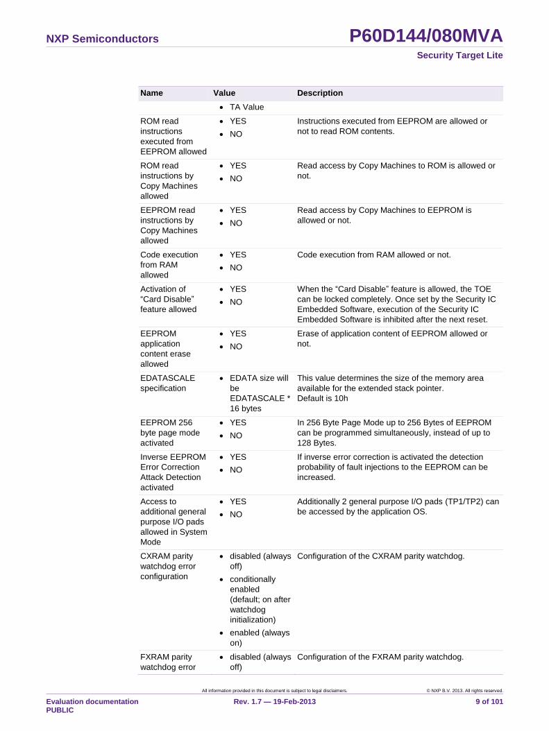
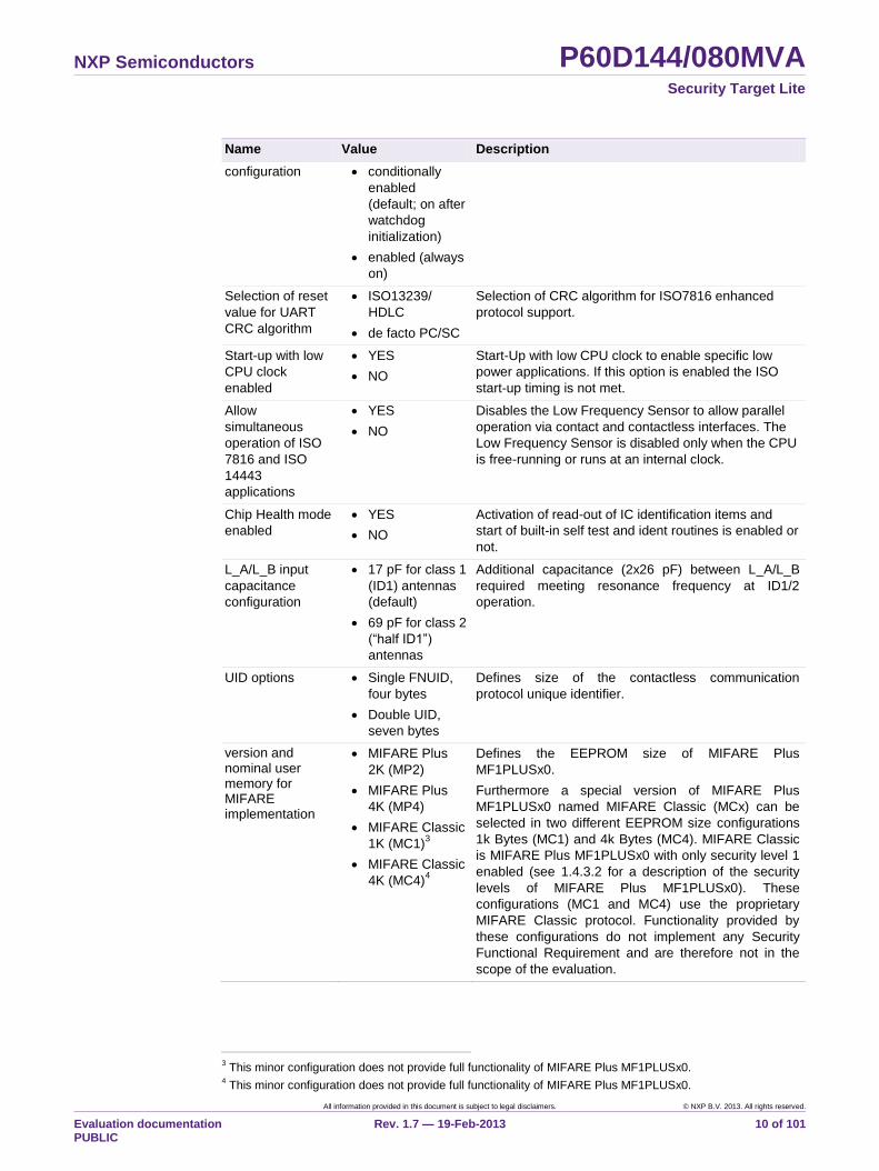
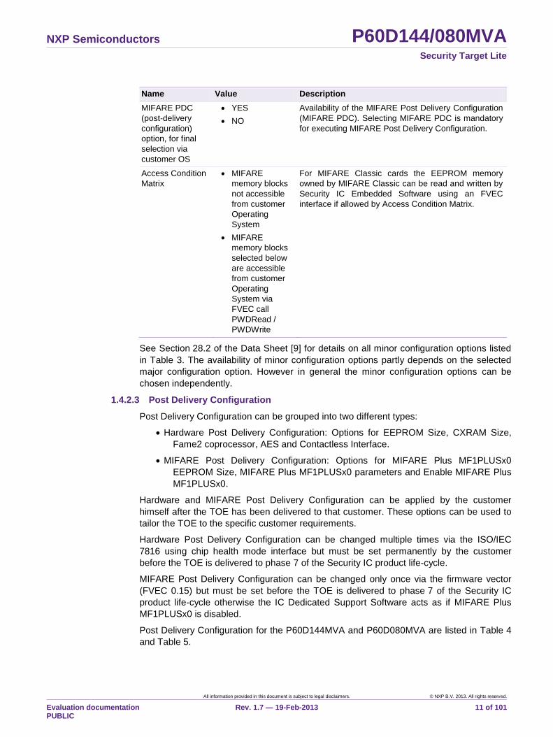
Table 3. Evaluated minor configuration options
Name Value Description
Resource
Configuration
Option (Hardware
PDC) enabled
YES
NO
Reconfiguration during card personalization enabled or
not.
Contactless
Communication
Parameters
ATQ0 Value
ATQ1 Value
SAK Value
Defines contactless communication protocol
parameters.
2 In the following always two copy machines are assumed to be available.
NXP Semiconductors P60D144/080MVA Security Target Lite
All information provided in this document is subject to legal disclaimers. © NXP B.V. 2013. All rights reserved.
Evaluation documentation PUBLIC
Rev. 1.7 — 19-Feb-2013 9 of 101
Name Value Description
TA Value
ROM read
instructions
executed from
EEPROM allowed
YES
NO
Instructions executed from EEPROM are allowed or
not to read ROM contents.
ROM read
instructions by
Copy Machines
allowed
YES
NO
Read access by Copy Machines to ROM is allowed or
not.
EEPROM read
instructions by
Copy Machines
allowed
YES
NO
Read access by Copy Machines to EEPROM is
allowed or not.
Code execution
from RAM
allowed
YES
NO
Code execution from RAM allowed or not.
Activation of
“Card Disable”
feature allowed
YES
NO
When the “Card Disable” feature is allowed, the TOE
can be locked completely. Once set by the Security IC
Embedded Software, execution of the Security IC
Embedded Software is inhibited after the next reset.
EEPROM
application
content erase
allowed
YES
NO
Erase of application content of EEPROM allowed or
not.
EDATASCALE
specification
EDATA size will
be
EDATASCALE *
16 bytes
This value determines the size of the memory area
available for the extended stack pointer.
Default is 10h
EEPROM 256
byte page mode
activated
YES
NO
In 256 Byte Page Mode up to 256 Bytes of EEPROM
can be programmed simultaneously, instead of up to
128 Bytes.
Inverse EEPROM
Error Correction
Attack Detection
activated
YES
NO
If inverse error correction is activated the detection
probability of fault injections to the EEPROM can be
increased.
Access to
additional general
purpose I/O pads
allowed in System
Mode
YES
NO
Additionally 2 general purpose I/O pads (TP1/TP2) can
be accessed by the application OS.
CXRAM parity
watchdog error
configuration
disabled (always
off)
conditionally
enabled
(default; on after
watchdog
initialization)
enabled (always
on)
Configuration of the CXRAM parity watchdog.
FXRAM parity
watchdog error
disabled (always
off)
Configuration of the FXRAM parity watchdog.
NXP Semiconductors P60D144/080MVA Security Target Lite
All information provided in this document is subject to legal disclaimers. © NXP B.V. 2013. All rights reserved.
Evaluation documentation PUBLIC
Rev. 1.7 — 19-Feb-2013 10 of 101
Name Value Description
configuration conditionally
enabled
(default; on after
watchdog
initialization)
enabled (always
on)
Selection of reset
value for UART
CRC algorithm
ISO13239/
HDLC
de facto PC/SC
Selection of CRC algorithm for ISO7816 enhanced
protocol support.
Start-up with low
CPU clock
enabled
YES
NO
Start-Up with low CPU clock to enable specific low
power applications. If this option is enabled the ISO
start-up timing is not met.
Allow
simultaneous
operation of ISO
7816 and ISO
14443
applications
YES
NO
Disables the Low Frequency Sensor to allow parallel
operation via contact and contactless interfaces. The
Low Frequency Sensor is disabled only when the CPU
is free-running or runs at an internal clock.
Chip Health mode
enabled
YES
NO
Activation of read-out of IC identification items and
start of built-in self test and ident routines is enabled or
not.
L_A/L_B input
capacitance
configuration
17 pF for class 1
(ID1) antennas
(default)
69 pF for class 2
(“half ID1”)
antennas
Additional capacitance (2x26 pF) between L_A/L_B
required meeting resonance frequency at ID1/2
operation.
UID options Single FNUID,
four bytes
Double UID,
seven bytes
Defines size of the contactless communication
protocol unique identifier.
version and nominal user memory for MIFARE implementation
MIFARE Plus
2K (MP2)
MIFARE Plus
4K (MP4)
MIFARE Classic
1K (MC1)3
MIFARE Classic
4K (MC4)4
Defines the EEPROM size of MIFARE Plus
MF1PLUSx0.
Furthermore a special version of MIFARE Plus
MF1PLUSx0 named MIFARE Classic (MCx) can be
selected in two different EEPROM size configurations
1k Bytes (MC1) and 4k Bytes (MC4). MIFARE Classic
is MIFARE Plus MF1PLUSx0 with only security level 1
enabled (see 1.4.3.2 for a description of the security
levels of MIFARE Plus MF1PLUSx0). These
configurations (MC1 and MC4) use the proprietary
MIFARE Classic protocol. Functionality provided by
these configurations do not implement any Security
Functional Requirement and are therefore not in the
scope of the evaluation.
3 This minor configuration does not provide full functionality of MIFARE Plus MF1PLUSx0.
4 This minor configuration does not provide full functionality of MIFARE Plus MF1PLUSx0.
NXP Semiconductors P60D144/080MVA Security Target Lite
All information provided in this document is subject to legal disclaimers. © NXP B.V. 2013. All rights reserved.
Evaluation documentation PUBLIC
Rev. 1.7 — 19-Feb-2013 11 of 101
Name Value Description
MIFARE PDC
(post-delivery
configuration)
option, for final
selection via
customer OS
YES
NO
Availability of the MIFARE Post Delivery Configuration
(MIFARE PDC). Selecting MIFARE PDC is mandatory
for executing MIFARE Post Delivery Configuration.
Access Condition
Matrix
MIFARE
memory blocks
not accessible
from customer
Operating
System
MIFARE
memory blocks
selected below
are accessible
from customer
Operating
System via
FVEC call
PWDRead /
PWDWrite
For MIFARE Classic cards the EEPROM memory
owned by MIFARE Classic can be read and written by
Security IC Embedded Software using an FVEC
interface if allowed by Access Condition Matrix.
See Section 28.2 of the Data Sheet [9] for details on all minor configuration options listed
in Table 3. The availability of minor configuration options partly depends on the selected
major configuration option. However in general the minor configuration options can be
chosen independently.
1.4.2.3 Post Delivery Configuration
Post Delivery Configuration can be grouped into two different types:
Hardware Post Delivery Configuration: Options for EEPROM Size, CXRAM Size,
Fame2 coprocessor, AES and Contactless Interface.
MIFARE Post Delivery Configuration: Options for MIFARE Plus MF1PLUSx0
EEPROM Size, MIFARE Plus MF1PLUSx0 parameters and Enable MIFARE Plus
MF1PLUSx0.
Hardware and MIFARE Post Delivery Configuration can be applied by the customer
himself after the TOE has been delivered to that customer. These options can be used to
tailor the TOE to the specific customer requirements.
Hardware Post Delivery Configuration can be changed multiple times via the ISO/IEC
7816 using chip health mode interface but must be set permanently by the customer
before the TOE is delivered to phase 7 of the Security IC product life-cycle.
MIFARE Post Delivery Configuration can be changed only once via the firmware vector
(FVEC 0.15) but must be set before the TOE is delivered to phase 7 of the Security IC
product life-cycle otherwise the IC Dedicated Support Software acts as if MIFARE Plus
MF1PLUSx0 is disabled.
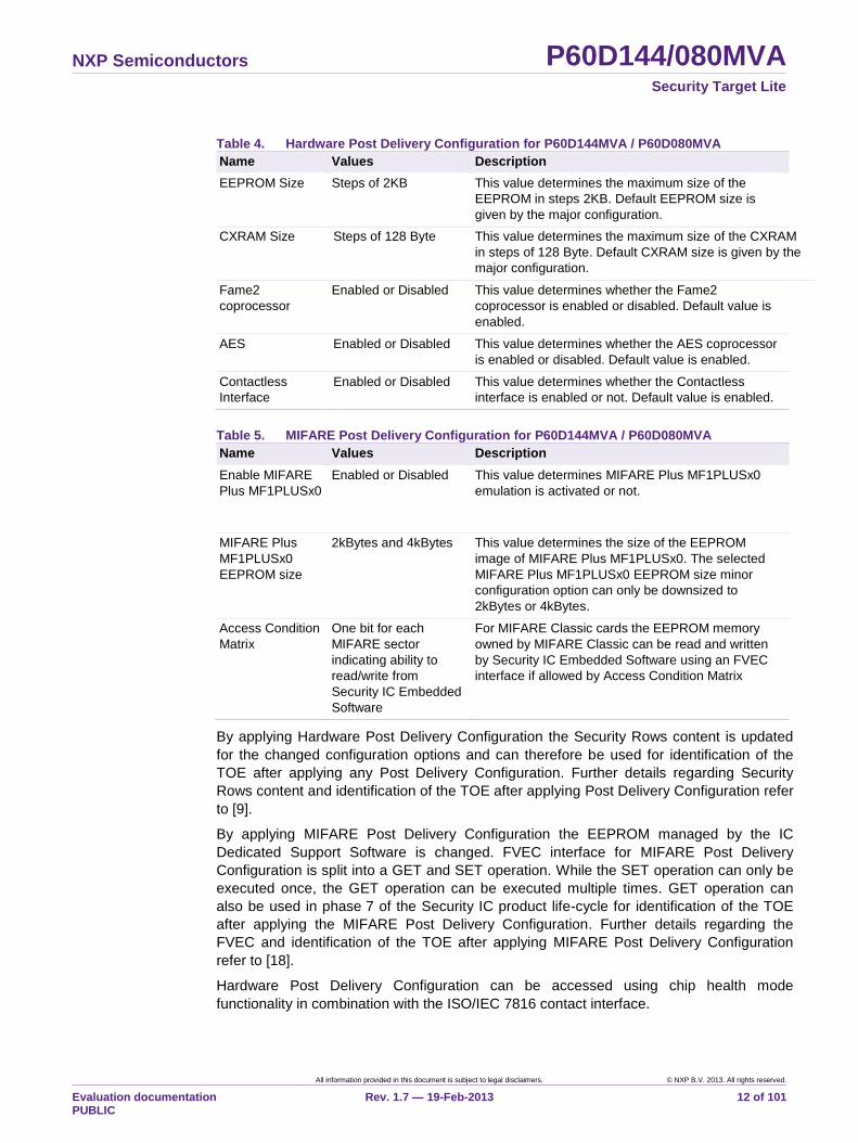
Post Delivery Configuration for the P60D144MVA and P60D080MVA are listed in Table 4
and Table 5.
NXP Semiconductors P60D144/080MVA Security Target Lite
All information provided in this document is subject to legal disclaimers. © NXP B.V. 2013. All rights reserved.
Evaluation documentation PUBLIC
Rev. 1.7 — 19-Feb-2013 12 of 101
Table 4. Hardware Post Delivery Configuration for P60D144MVA / P60D080MVA
Name Values Description
EEPROM Size Steps of 2KB This value determines the maximum size of the
EEPROM in steps 2KB. Default EEPROM size is
given by the major configuration.
CXRAM Size Steps of 128 Byte This value determines the maximum size of the CXRAM
in steps of 128 Byte. Default CXRAM size is given by the
major configuration.
Fame2
coprocessor
Enabled or Disabled This value determines whether the Fame2
coprocessor is enabled or disabled. Default value is
enabled.
AES Enabled or Disabled This value determines whether the AES coprocessor
is enabled or disabled. Default value is enabled.
Contactless
Interface
Enabled or Disabled This value determines whether the Contactless
interface is enabled or not. Default value is enabled.
Table 5. MIFARE Post Delivery Configuration for P60D144MVA / P60D080MVA
Name Values Description
Enable MIFARE
Plus MF1PLUSx0
Enabled or Disabled This value determines MIFARE Plus MF1PLUSx0
emulation is activated or not.
MIFARE Plus
MF1PLUSx0
EEPROM size
2kBytes and 4kBytes This value determines the size of the EEPROM
image of MIFARE Plus MF1PLUSx0. The selected
MIFARE Plus MF1PLUSx0 EEPROM size minor
configuration option can only be downsized to
2kBytes or 4kBytes.
Access Condition
Matrix
One bit for each
MIFARE sector
indicating ability to
read/write from
Security IC Embedded
Software
For MIFARE Classic cards the EEPROM memory
owned by MIFARE Classic can be read and written
by Security IC Embedded Software using an FVEC
interface if allowed by Access Condition Matrix
By applying Hardware Post Delivery Configuration the Security Rows content is updated
for the changed configuration options and can therefore be used for identification of the
TOE after applying any Post Delivery Configuration. Further details regarding Security
Rows content and identification of the TOE after applying Post Delivery Configuration refer
to [9].
By applying MIFARE Post Delivery Configuration the EEPROM managed by the IC
Dedicated Support Software is changed. FVEC interface for MIFARE Post Delivery
Configuration is split into a GET and SET operation. While the SET operation can only be
executed once, the GET operation can be executed multiple times. GET operation can
also be used in phase 7 of the Security IC product life-cycle for identification of the TOE
after applying the MIFARE Post Delivery Configuration. Further details regarding the
FVEC and identification of the TOE after applying MIFARE Post Delivery Configuration
refer to [18].
Hardware Post Delivery Configuration can be accessed using chip health mode
functionality in combination with the ISO/IEC 7816 contact interface.
NXP Semiconductors P60D144/080MVA Security Target Lite
All information provided in this document is subject to legal disclaimers. © NXP B.V. 2013. All rights reserved.
Evaluation documentation PUBLIC
Rev. 1.7 — 19-Feb-2013 13 of 101
MIFARE Post Delivery Configuration can be accessed using the FVEC interface (FVEC
0.15). This means that MIFARE Post Delivery Configuration must be done by the Security
IC Embedded Software before phase 7 of the Security IC product life-cycle.
1.4.2.4 Evaluated package types
A number of package types are supported for each major configuration of the TOE. The
commercial types are named according to the following format. The commercial type
name of each major configuration varies with the package type as indicated by the
variable pp and with the Security IC Embedded Software as indicated by the variables rr
and ff. M identifies the activation of MIFARE Plus MF1PLUSx0. Variable o identifies the
EEPROM size of the MIFARE Plus MF1PLUSx0. The number 9 is used as Fab identifier
and A references to the silicon version also available at major configuration naming as VA.
The variables are replaced according to the rules in Table 6.
P60D144Mpp(p)/9Arrffo for major configuration P60D144MVA
P60D080Mpp(p)/9Arrffo for major configuration P60D080MVA
Table 6. Variable definitions for commercial type names
Variable Definition
M OS Emulation Option Configuration for Dual Interface Types (alpha numeric),
„M‟ for MIFARE Plus MF1PLUSx0.
pp(p) Package delivery type (alpha numeric, last character optional), e.g. “A4” for
MOB4 module.
rr ROM code number, which identifies the ROM mask.
ff FabKey number, which identifies the EEPROM content at TOE delivery.
o Size of EEPROM area for MIFARE Plus MF1PLUSx0 e.g. „2‟ 2kBytes
EEPROM size (MIFARE Plus MF1PLUSx0).
For a detailed description of the package type names please refer to [12].
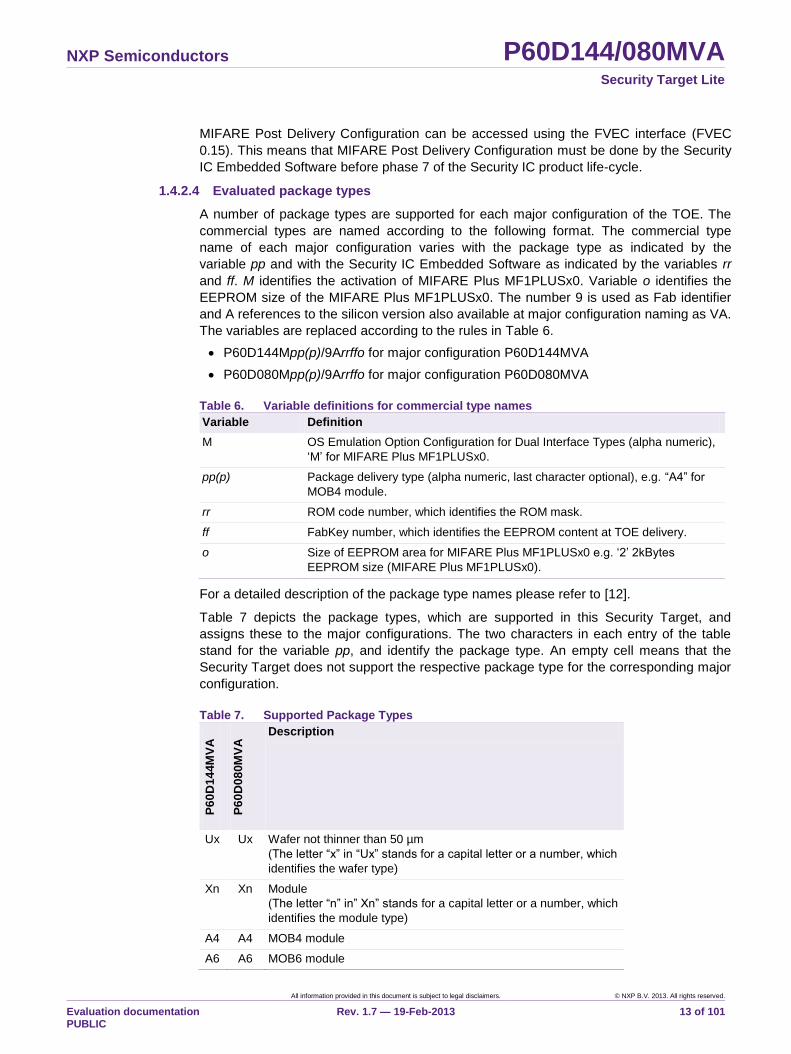
Table 7 depicts the package types, which are supported in this Security Target, and
assigns these to the major configurations. The two characters in each entry of the table
stand for the variable pp, and identify the package type. An empty cell means that the
Security Target does not support the respective package type for the corresponding major
configuration.
Table 7. Supported Package Types
P6
0D
14
4M
VA
P6
0D
08
0M
VA
Description
Ux Ux Wafer not thinner than 50 µm
(The letter “x” in “Ux” stands for a capital letter or a number, which
identifies the wafer type)
Xn Xn Module
(The letter “n” in” Xn” stands for a capital letter or a number, which
identifies the module type)
A4 A4 MOB4 module
A6 A6 MOB6 module
NXP Semiconductors P60D144/080MVA Security Target Lite
All information provided in this document is subject to legal disclaimers. © NXP B.V. 2013. All rights reserved.
Evaluation documentation PUBLIC
Rev. 1.7 — 19-Feb-2013 14 of 101
P6
0D
14
4M
VA
P6
0D
08
0M
VA
Description
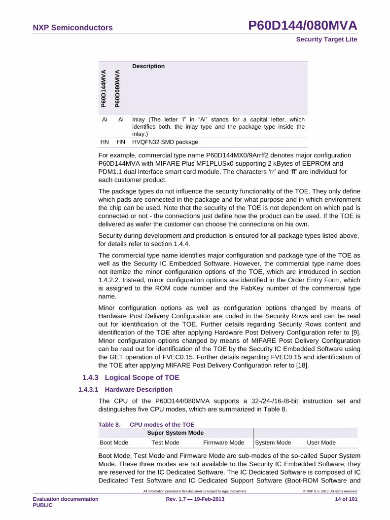
Ai Ai Inlay (The letter „i” in “Ai” stands for a capital letter, which
identifies both, the inlay type and the package type inside the
inlay.)
HN HN HVQFN32 SMD package
For example, commercial type name P60D144MX0/9Arrff2 denotes major configuration
P60D144MVA with MIFARE Plus MF1PLUSx0 supporting 2 kBytes of EEPROM and
PDM1.1 dual interface smart card module. The characters „rr‟ and „ff‟ are individual for
each customer product.
The package types do not influence the security functionality of the TOE. They only define
which pads are connected in the package and for what purpose and in which environment
the chip can be used. Note that the security of the TOE is not dependent on which pad is
connected or not - the connections just define how the product can be used. If the TOE is
delivered as wafer the customer can choose the connections on his own.
Security during development and production is ensured for all package types listed above,
for details refer to section 1.4.4.
The commercial type name identifies major configuration and package type of the TOE as
well as the Security IC Embedded Software. However, the commercial type name does
not itemize the minor configuration options of the TOE, which are introduced in section
1.4.2.2. Instead, minor configuration options are identified in the Order Entry Form, which
is assigned to the ROM code number and the FabKey number of the commercial type
name.
Minor configuration options as well as configuration options changed by means of
Hardware Post Delivery Configuration are coded in the Security Rows and can be read
out for identification of the TOE. Further details regarding Security Rows content and
identification of the TOE after applying Hardware Post Delivery Configuration refer to [9].
Minor configuration options changed by means of MIFARE Post Delivery Configuration
can be read out for identification of the TOE by the Security IC Embedded Software using
the GET operation of FVEC0.15. Further details regarding FVEC0.15 and identification of
the TOE after applying MIFARE Post Delivery Configuration refer to [18].
1.4.3 Logical Scope of TOE
1.4.3.1 Hardware Description
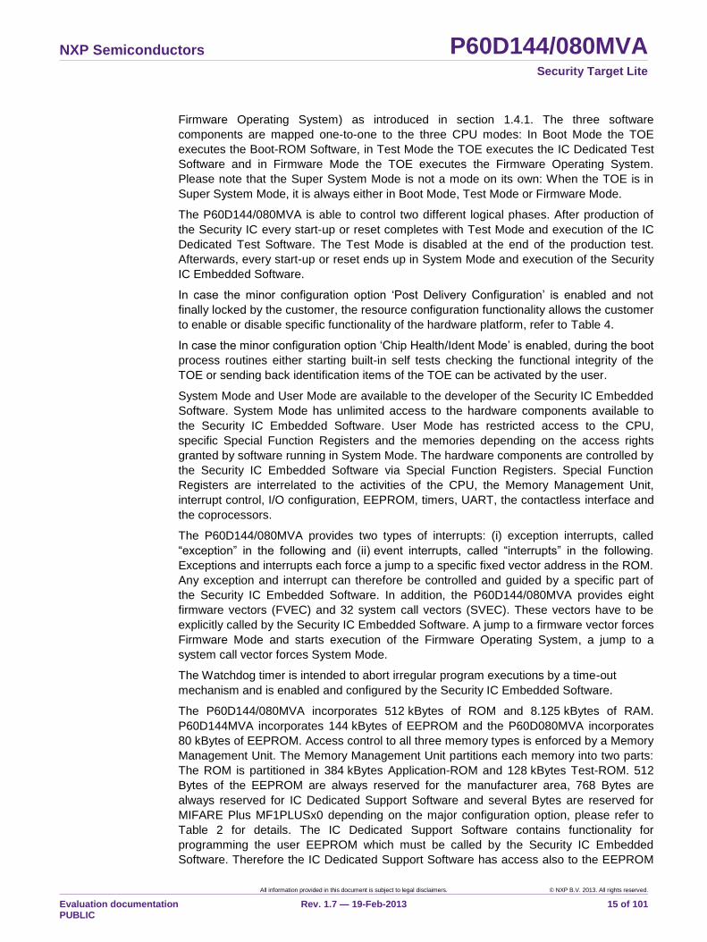
The CPU of the P60D144/080MVA supports a 32-/24-/16-/8-bit instruction set and
distinguishes five CPU modes, which are summarized in Table 8.
Table 8. CPU modes of the TOE
Super System Mode
Boot Mode Test Mode Firmware Mode System Mode User Mode
Boot Mode, Test Mode and Firmware Mode are sub-modes of the so-called Super System
Mode. These three modes are not available to the Security IC Embedded Software; they
are reserved for the IC Dedicated Software. The IC Dedicated Software is composed of IC
Dedicated Test Software and IC Dedicated Support Software (Boot-ROM Software and
NXP Semiconductors P60D144/080MVA Security Target Lite
All information provided in this document is subject to legal disclaimers. © NXP B.V. 2013. All rights reserved.
Evaluation documentation PUBLIC
Rev. 1.7 — 19-Feb-2013 15 of 101
Firmware Operating System) as introduced in section 1.4.1. The three software
components are mapped one-to-one to the three CPU modes: In Boot Mode the TOE
executes the Boot-ROM Software, in Test Mode the TOE executes the IC Dedicated Test
Software and in Firmware Mode the TOE executes the Firmware Operating System.
Please note that the Super System Mode is not a mode on its own: When the TOE is in
Super System Mode, it is always either in Boot Mode, Test Mode or Firmware Mode.
The P60D144/080MVA is able to control two different logical phases. After production of
the Security IC every start-up or reset completes with Test Mode and execution of the IC
Dedicated Test Software. The Test Mode is disabled at the end of the production test.
Afterwards, every start-up or reset ends up in System Mode and execution of the Security
IC Embedded Software.
In case the minor configuration option „Post Delivery Configuration‟ is enabled and not
finally locked by the customer, the resource configuration functionality allows the customer
to enable or disable specific functionality of the hardware platform, refer to Table 4.
In case the minor configuration option „Chip Health/Ident Mode‟ is enabled, during the boot
process routines either starting built-in self tests checking the functional integrity of the
TOE or sending back identification items of the TOE can be activated by the user.
System Mode and User Mode are available to the developer of the Security IC Embedded
Software. System Mode has unlimited access to the hardware components available to
the Security IC Embedded Software. User Mode has restricted access to the CPU,
specific Special Function Registers and the memories depending on the access rights
granted by software running in System Mode. The hardware components are controlled by
the Security IC Embedded Software via Special Function Registers. Special Function
Registers are interrelated to the activities of the CPU, the Memory Management Unit,
interrupt control, I/O configuration, EEPROM, timers, UART, the contactless interface and
the coprocessors.
The P60D144/080MVA provides two types of interrupts: (i) exception interrupts, called
“exception” in the following and (ii) event interrupts, called “interrupts” in the following.
Exceptions and interrupts each force a jump to a specific fixed vector address in the ROM.
Any exception and interrupt can therefore be controlled and guided by a specific part of
the Security IC Embedded Software. In addition, the P60D144/080MVA provides eight
firmware vectors (FVEC) and 32 system call vectors (SVEC). These vectors have to be
explicitly called by the Security IC Embedded Software. A jump to a firmware vector forces
Firmware Mode and starts execution of the Firmware Operating System, a jump to a
system call vector forces System Mode.
The Watchdog timer is intended to abort irregular program executions by a time-out
mechanism and is enabled and configured by the Security IC Embedded Software.
The P60D144/080MVA incorporates 512 kBytes of ROM and 8.125 kBytes of RAM.
P60D144MVA incorporates 144 kBytes of EEPROM and the P60D080MVA incorporates
80 kBytes of EEPROM. Access control to all three memory types is enforced by a Memory
Management Unit. The Memory Management Unit partitions each memory into two parts:
The ROM is partitioned in 384 kBytes Application-ROM and 128 kBytes Test-ROM. 512
Bytes of the EEPROM are always reserved for the manufacturer area, 768 Bytes are
always reserved for IC Dedicated Support Software and several Bytes are reserved for
MIFARE Plus MF1PLUSx0 depending on the major configuration option, please refer to
Table 2 for details. The IC Dedicated Support Software contains functionality for
programming the user EEPROM which must be called by the Security IC Embedded
Software. Therefore the IC Dedicated Support Software has access also to the EEPROM
NXP Semiconductors P60D144/080MVA Security Target Lite
All information provided in this document is subject to legal disclaimers. © NXP B.V. 2013. All rights reserved.
Evaluation documentation PUBLIC
Rev. 1.7 — 19-Feb-2013 16 of 101
area which is allocated to the Security IC Embedded Software, the separation between
user data and NXP firmware data is guaranteed by means of a software firewall. 896
Bytes of RAM are allocated for the Firmware Operating System and the remaining part for
the application. Note that the ROM size is displayed as 384 kBytes in the block diagram in
Fig 1 because only 384 kBytes are available to the Security IC Embedded Software.
In Test Mode the CPU has unrestricted access to all memories. In Boot Mode and
Firmware Mode access is limited to the Test-ROM, the manufacturer area of the EEPROM
and its configured part of 768 Bytes and the EEPROM space owned by MIFARE Plus
MF1PLUSx0 as well as the configured part of 896 Bytes RAM for the Firmware Operating
System. All other parts of the memories are accessible in System Mode and User Mode,
namely the Application-ROM and the larger parts of EEPROM and RAM. User Mode is
further restricted by the Memory Management Unit, which can be configured in System
Mode.
The RAM, which is available to the Security IC Embedded Software, is further split in two
parts. These are 4.625 kBytes general purpose RAM and 2.625 kBytes FXRAM
(associated to the Fame2 coprocessor). Both parts are accessible to the CPU, but the
Fame2 coprocessor can only access the FXRAM. The Fame2 coprocessor can access
the FXRAM without control of access rights by the Memory Management Unit. Since the
Memory Management Unit does not control accesses of the Fame2 coprocessor, software
which has access to the Fame2 coprocessor implicitly has access to the FXRAM.
The Triple-DES coprocessor supports single DES and Triple-DES operations. Only Triple-
DES is in the scope of this evaluation, in 2-key or 3-key operation with two/three 56-bit
keys (112-/168-bit). The AES coprocessor supports AES operation with three different key
lengths of 128, 192 or 256 bit. The Fame2 coprocessor supplies basic arithmetic functions
to support implementation of asymmetric cryptographic algorithms by the Security IC
Embedded Software. The random generator provides true random numbers without
pseudo random calculation. The CRC coprocessor provides CRC generation polynomial
CRC-16 and CRC-32. The copy machine supports a mechanism to transfer data between
specific Special Function Registers as well as memories without interaction of the CPU.
The P60D144/080MVA operates with a single external power supply of 1.8 V, 3 V or 5 V
nominal. Alternatively the P60D144/080MVA can be supplied via the RF interface by
inductive coupling. The maximum external clock frequency used for synchronization of the
ISO/IEC 7816 communication is 10 MHz nominal, the CPU and all co-processors are
supplied exclusively with an internally generated clock signal which frequency can be
selected by the Security IC Embedded Software. The P60D144/080MVA provides power
saving modes with reduced activity. These are named IDLE Mode and SLEEP Mode, of
which the latter one includes CLOCK STOP Mode.
The TOE protects secret data, which are stored to and operated by the TOE, against
physical tampering. A memory encryption is added to the memories RAM, ROM and
EEPROM. EEPROM double read function is included in this memory to check data
consistency during EEPROM read. Chip shielding is added in form of active and passive
shield over logic and memories. Sensors in form of light, voltage, temperature and
frequency sensors are distributed over the chip area. The security functionality of the IC
hardware platform is mainly provided by the TOE, and completed by the Security IC
Embedded Software. This causes dependencies between the security functionality of the
TOE and the security functionality provided by the Security IC Embedded Software.
NXP Semiconductors P60D144/080MVA Security Target Lite
All information provided in this document is subject to legal disclaimers. © NXP B.V. 2013. All rights reserved.
Evaluation documentation PUBLIC
Rev. 1.7 — 19-Feb-2013 17 of 101
1.4.3.2 Software Description
Operating system and applications of a Security IC are developed by the customers and
included under the heading Security IC Embedded Software. The Security IC Embedded
Software is stored in the Application-ROM and/or in the Application-EEPROM and is not
part of the TOE. The Security IC Embedded Software depends on the usage of the IC
hardware platform.
The IC Dedicated Test Software, is stored to the Test-ROM and used by the manufacturer
of the Security IC during production test. The test functionality is disabled before the TOE
is delivered (operational use of the Security IC) by disabling the Test Mode of the CPU in
hardware. The IC Dedicated Test Software is developed by NXP and embedded in the
Test-ROM. The IC Dedicated Test Software includes the test operating system, test
routines for the various blocks of the circuitry, control flags for the status of the EEPROM‟s
manufacturer area and shutdown functions to ensure that security relevant test routines
cannot be executed illegally after phase 3.
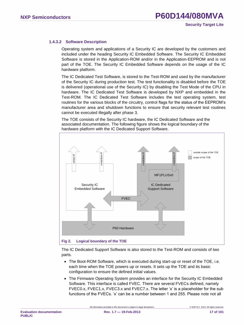
The TOE consists of the Security IC hardware, the IC Dedicated Software and the associated documentation. The following figure shows the logical boundary of the hardware platform with the IC Dedicated Support Software.
Security IC
Embedded Software
co
nta
ct IF
co
nta
ctle
ss IF
IC Dedicated
Support Software
P60 Hardware
FVEC
MF1PLUSx0co
nta
ctle
ss IF
co
nta
ctle
ss IF outside scope of the TOE
scope of the TOE
Fig 2. Logical boundary of the TOE
The IC Dedicated Support Software is also stored to the Test-ROM and consists of two
parts.
The Boot-ROM Software, which is executed during start-up or reset of the TOE, i.e.
each time when the TOE powers up or resets. It sets up the TOE and its basic
configuration to ensure the defined initial values.
The Firmware Operating System provides an interface for the Security IC Embedded
Software. This interface is called FVEC. There are several FVECs defined, namely
FVEC0.x, FVEC1.x, FVEC3.x and FVEC7.x. The letter „x‟ is a placeholder for the sub
functions of the FVECs. „x‟ can be a number between 1 and 255. Please note not all
NXP Semiconductors P60D144/080MVA Security Target Lite
All information provided in this document is subject to legal disclaimers. © NXP B.V. 2013. All rights reserved.
Evaluation documentation PUBLIC
Rev. 1.7 — 19-Feb-2013 18 of 101
sub numbers are valid. Therefore please refer to [18] for a detailed description of the
FVEC interface and all sub functions.
FVEC0.x: This interface establishes the contactless communication according to
ISO/IEC 14443 for the Security IC Embedded Software. Furthermore it provides
sub functions to enable MIFARE Plus MF1PLUSx0.
FVEC1.x: This interface is used to access the EEPROM owned by MIFARE Plus
MF1PLUSx0 when in security level 1 or security level 2. MIFARE Plus MF1PLUSx0
in security level 1 or security level 2 does not implement any Security Functional
Requirement and therefore FVEC1.x is not in the scope of the evaluation.
FVEC3.x: This interface is used to access the EEPROM owned by MIFARE Plus
MF1PLUSx0. It only handles MIFARE Plus MF1PLUSx0 commands specified for
ISO14443-4. This includes all security level 0 and security level 3 commands and
the security level switch commands in security level 1 and security level 2.
FVEC7.x: This interface implements programming of the internal EEPROM
memory, which is mandatory for use by the Security IC Embedded Software when
programming the EEPROM memory.
FOS includes the MIFARE Plus MF1PLUSx0, which is started by an FVEC call, as
described above, of the Security IC Embedded Software. The MIFARE Plus
MF1PLUSx0 provides the following functionality:
A data storage system that contains blocks grouped in sectors which can store
data (including so-called values which are blocks in a specific format representing
a number).
Authentication on sector level with fine-grained access conditions blocks.
Message authentication to support replay attack protection.
Data encryption for confidentiality of the contact-less communication.
Unique serial number for each device (UID) with optional random UID.
MIFARE Plus MF1PLUSx0 offers four security levels, but can only be in one security
level at a time. The main features of each security level are listed below:
Security level 0: The MIFARE Plus MF1PLUSx0 does not provide any functionality
besides initialization. The MIFARE Plus MF1PLUSx0 is initialized in
plaintext, especially keys for the further levels can be brought in. A
MIFARE Plus MF1PLUSx0 in security level 0 is not usable for other
purposes. After all mandatory keys and security attributes have
been stored in the MIFARE Plus MF1PLUSx0 local EEPROM it
shall be switched to a higher security level.
Security level 1: The card user can access the blocks in the card after an
authentication procedure performed according to the MIFARE
Classic proprietary protocol. The communication with the terminal is
done using the MIFARE Classic proprietary protocol. Functionality
provided by security level 1 does not implement any Security
Functional Requirement and is therefore not in the scope of the
evaluation. The only exception is the security level switch.
Note: In security level 1 it is possible to switch to a higher security
level if an authentication using the AES algorithm with the
necessary key is performed.
Note: MIFARE Plus MF1PLUSx0 in security level 1 is also referred
to as MIFARE Classic. MIFARE Plus MF1PLUSx0 can be
NXP Semiconductors P60D144/080MVA Security Target Lite
All information provided in this document is subject to legal disclaimers. © NXP B.V. 2013. All rights reserved.
Evaluation documentation PUBLIC
Rev. 1.7 — 19-Feb-2013 19 of 101
configured in a way that only MIFARE Classic functionality, which
do not implement any Security Functional Requirement and is
therefore not in the scope of the evaluation, is available to the
Security IC Embedded Software (see minor configuration option
“version and nominal user memory for MIFARE implementation”
values MC1 and MC4).5
Security level 2: The card user can access the blocks in the card after an
authentication procedure involving an authentication using the AES
algorithm and an authentication using the MIFARE Classic
proprietary protocol. The communication with the terminal is done
using the MIFARE Classic proprietary protocol. Functionality
provided by security level 2 does not implement any Security
Functional Requirement and is therefore not in the scope of the
evaluation. The only exception is the security level switch.
Note: In security level 2 it is possible to switch to a higher security
level if an authentication using the AES algorithm with the
necessary key is performed.
Security level 3: The card user can access the data and value blocks in the card via
an adequate card terminal after an authentication procedure based
on the AES algorithm. The communication with the card terminal
can be protected with secure messaging. The authentication and
the secure messaging are security services of the TOE. The TOE
cannot be switched to a different security level.
The TOE provides the Security Services assigned to the MIFARE Plus MF1PLUSx0 in
security level 3. In addition the personalisation in security level 0, the originality
function, which allows verifying the authenticity of the TOE in all security levels, as
well as the switching from security level 1 and security level 2 into security level 3 are
within the scope of the evaluation.
Note: Communication with the card terminal in security level 1 and security level 2 use
the proprietary MIFARE Classic protocol, which do not implement any Security
Functional Requirement and is therefore not in the scope of the evaluation.
The MIFARE Plus MF1PLUSx0 security level 0 is intended for personalisation in
phase 6 according to the [6], section 1.2.4. The security levels 1 to 3 are intended for
the phase 7 of the Security IC product life-cycle.
The execution of the Firmware Operating System is separated by security
mechanisms implemented in the hardware including the firewall separation of the
Firmware Mode controlling the access to memories and Special Function Registers as
configured in hardware or by the Security IC Embedded Software.
The TOE is always delivered with a Firmware Operating System. The related
functionality is part of the hardware platform evaluation. The Firmware Operating
System of the TOE includes the control of hardware related functionality, the resource
configuration functionality and the MIFARE Plus MF1PLUSx0.
1.4.3.3 Documentation
The data sheet “Data Sheet SmartMX2 family P60D080/144 and P60C080/144, Secure
high-performance smart card controller” [9] contains a functional description and
guidelines for the use of the security functionality, as needed to develop Security IC
Embedded Software. The instruction set of the CPU is described in “Instruction Set for the
5 These minor configurations do not provide full functionality of MIFARE Plus MF1PLUSx0.
NXP Semiconductors P60D144/080MVA Security Target Lite
All information provided in this document is subject to legal disclaimers. © NXP B.V. 2013. All rights reserved.
Evaluation documentation PUBLIC
Rev. 1.7 — 19-Feb-2013 20 of 101
SmartMX2 family, Secure smart card controller” [10]. The manual “NXP Secure Smart
Card Controller P60x080/P60x144VA Guidance and Operation Manual” [11] describes
aspects of the program interface and the use of programming techniques to improve the
security. The wafer and delivery specification “SmartMX2 family P60D080/144 VA and
P60C080/144 VA Wafer and delivery specification, NXP Semiconductors, Business Unit
Identification” [12] describes physical identification of the TOE and the secure delivery
process. The functional specification of the MIFARE Plus MF1PLUSx0 is described in
”MIFARE Plus Functionality of implementations on smart card controllers” [15] The whole
documentation shall be used by the developer to develop the Security IC Embedded
Software. The FVEC interface of the IC Dedicated Support Software is described in
“SmartMX2 family Firmware Interface Specification, Product data sheet addendum, NXP
Semiconductors, Business Unit Identification” [18]. The guidance, delivery and operation
for MIFARE Plus MF1PLUSx0 is described in “MIFARE Plus MF1PLUSx0 Guidance,
Delivery and Operation Manual, NXP Secure Smart Card Controller P60xeeey with
MF1PLUSx0, NXP Semiconductors, Business Unit Identification” [19] assuring secure
operation of MIFARE Plus MF1PLUSx0.
1.4.4 Security during Development and Production
The Security IC product life-cycle is scheduled in phases as introduced in the PP [6]. IC
Development as well as IC Manufacturing and Testing, which are phases 2 and 3 of the
life-cycle, are part of the evaluation. Phase 4 the IC Packaging is also part of the
evaluation. The Security IC is delivered at the end of phase 3 or phase 4 in the life-cycle.
The development and production environment of the TOE ranges from phase 2 to TOE
Delivery.
With respect to Application Note 3 in [6] the TOE supports the authentic delivery using the
“Chip Health/Ident Mode” and the FabKey feature. For further details on these features
please refer to the data sheet [9] and the guidance and operation manual [11].
During the design and the layout process only people involved in the specific development
project for an IC have access to sensitive data. Different people are responsible for the
design data and for customer related data.
The production of the wafers includes two different steps regarding the production flow. In
the first step the wafers are produced with the fixed masks independent of the customer.
After that step the wafers are completed with the customer specific mask, including the
ROM Code, and the remaining mask set.
The test process of every die is performed by a test centre of NXP. Delivery processes
between the involved sites provide accountability and traceability of the TOE. NXP
embeds the dice into modules, inlays or packages based on customer demand.
Information about non-functional items is stored on magnetic/optical media enclosed with
the delivery or the non-functional items are physically marked. In summary, the TOE can
be delivered in four different forms, which are
dice on wafers
smartcard modules on a module reel
inlays
packaged devices in tubes or reels
The availability of major configuration options of the TOE in package types is detailed in
section 1.4.2.4.
NXP Semiconductors P60D144/080MVA Security Target Lite
All information provided in this document is subject to legal disclaimers. © NXP B.V. 2013. All rights reserved.
Evaluation documentation PUBLIC
Rev. 1.7 — 19-Feb-2013 21 of 101
1.4.5 TOE Intended Usage
The end-consumer environment of the TOE is phase 7 of the Security IC product life-cycle
as defined in the PP [6]. In this phase the Security IC product is in usage by the end-
consumer. Its method of use now depends on the Security IC Embedded Software. The
Security ICs including the P60D144/080MVA can be used to assure authorized conditional
access in a wide range of applications. Examples are identity cards, Banking Cards, Pay-
TV, Portable communication SIM cards, Health cards and Transportation cards. The end-
user environment covers a wide spectrum of very different functions, thus making it
difficult to monitor and avoid abuse of the TOE. The TOE is intended to be used in an
insecure environment, which does not protect against threats.
The device is developed for most high-end safeguarded applications, and is designed for
embedding into chip cards according to ISO/IEC 7816 [23] and for contactless
applications according to ISO/IEC 14443 [25]. Usually a Security IC (e.g. a smartcard) is
assigned to a single individual only, but it may also be used by multiple applications in a
multi-provider environment. Therefore the TOE might store and process secrets of several
systems, which must be protected from each other. The TOE then must meet security
requirements for each single security module. Secret data shall be used as input for
calculation of authentication data, calculation of signatures and encryption of data and
keys.
The Security IC Embedded Software can call the MIFARE Plus MF1PLUSx0 that is part of
the TOE. The intended usage of the TOE requires that MIFARE Plus MF1PLUSx0 is
personalized in security level 0 within a secure environment and is switched to security
level 3 afterwards. If MIFARE Plus MF1PLUSx0 is in security level 3 and is called it
provides its own security functionality and operates independent of the Security IC
Embedded Software on the memory partitions assigned to MIFARE Plus MF1PLUSx0.
MIFARE Plus MF1PLUSx0 supports MIFARE Plus compatible applications in the field of:
Electronic fare collection
Stored value card systems
Access control systems
Loyalty
If privacy is an issue, the MIFARE Plus MF1PLUSx0 can be configured not to disclose any
information to unauthorized users. However in this case also the application(s)
implemented in the Security IC Embedded Software must support this privacy issue.
Otherwise the privacy enforced by the MIFARE Plus MF1PLUSx0 can be circumvented by
selecting another application of the TOE.
In development and production environment of the TOE the Security IC Embedded
Software developer and system integrators such as the terminal software developer may
use samples of the TOE for their testing purposes. It is not intended that they are able to
change the behaviour of the Security IC in another way than an end-consumer.
The user environment of the TOE ranges from TOE delivery to phase 7 of the Security IC
product life-cycle, and must be a controlled environment up to phase 6.
Note: The phases from TOE Delivery to phase 7 of the Security IC Product life-
cycle are not part of the TOE construction process in the sense of this
Security Target. Information about these phases is just included to describe
how the TOE is used after its construction. Nevertheless such security
NXP Semiconductors P60D144/080MVA Security Target Lite
All information provided in this document is subject to legal disclaimers. © NXP B.V. 2013. All rights reserved.
Evaluation documentation PUBLIC
Rev. 1.7 — 19-Feb-2013 22 of 101
functionality of the TOE, that is independent of the Security IC Embedded
Software, is active at TOE Delivery and cannot be disabled by the Security
IC Embedded Software in the following phases.
1.4.6 Interface of the TOE
The electrical interface of the P60D144/080MVA are the pads to connect the lines power
supply, ground, reset input, clock input, serial communication pads I/O1, I/O2, I/O3 and
depending on a minor configuration option TP1 and TP2, as well as two pads (called LA
and LB) for the antenna of the RF interface. Communication with the TOE can be
established via the contact interface through the ISO/IEC 7816 UART or direct usage of
the I/O ports. Contactless communication is done via the contactless interface unit (CIU)
compatible to ISO/IEC 14443.
The logical interface of the TOE depends on the CPU mode and the associated software.
In Boot Mode the Boot-ROM Software is executed. Only in case the minor
configuration option “Chip Health/Ident Mode” is enabled, starting of built-in self test
routines and read-out of TOE identification items is supported. If this minor
configuration option is disabled the Boot-ROM Software provides no interface. In this
case there is no possibility to interact with this software.
In Test Mode (used before TOE delivery) the logical interface visible on the electrical
interface is defined by the IC Dedicated Test Software. This IC Dedicated Test
Software comprises the test operating system and the package of test function calls.
In Firmware Mode the Firmware Operating System is executed by the CPU. The
Firmware Mode is always requested by the Security IC Embedded Software via an
FVEC call please refer to [9] for more information.
The MIFARE Plus MF1PLUSx0 is part of the FOS and can be executed by using a
specific FVEC call. The interface of the MIFARE Plus MF1PLUSx0 comprises the
command interface as defined by the functional specification of the MIFARE Plus
MF1PLUSx0, refer to [15].
In System Mode and User Mode (after TOE Delivery) the software interface is the set
of instructions, the bits in the special function registers that are related to these modes
and the physical address map of the CPU including memories. The access to the
special function registers as well as to the memories depends on the CPU mode
configured by the Security IC Embedded Software.
Note: The logical interface of the TOE that is visible on the electrical interface after
TOE Delivery is based on the Security IC Embedded Software developed by
the software developer. The identification and authentication of the user in
System Mode or User Mode must be controlled by the Security IC
Embedded Software.
The chip surface can be seen as an interface of the TOE, too. This interface must be
taken into account regarding environmental stress e.g. like temperature and in the case of
an attack, for which the attacker manipulates the chip surface.
Note: An external voltage and timing supply as well as a logical interface are
necessary for the operation of the TOE. Beyond the physical behaviour the
logical interface is defined by the Security IC Embedded Software.
NXP Semiconductors P60D144/080MVA Security Target Lite
All information provided in this document is subject to legal disclaimers. © NXP B.V. 2013. All rights reserved.
Evaluation documentation PUBLIC
Rev. 1.7 — 19-Feb-2013 23 of 101
2. Conformance Claims
This chapter is divided into the following sections: “CC Conformance Claim”, “Package
claim”, “PP claim” and “Conformance Claim Rationale”.
2.1 CC Conformance Claim
This Security Target and the TOE claims to be conformant to version 3.1 of Common
Criteria for Information Technology Security Evaluation according to
“Common Criteria for Information Technology Security Evaluation, Part 1: Introduction
and general model, Version 3.1, Revision 3, July 2009, CCMB-2009-07-001” [1]
“Common Criteria for Information Technology Security Evaluation, Part 2: Security
functional components, Version 3.1, Revision 3, July 2009, CCMB-2009-07-002” [2]
“Common Criteria for Information Technology Security Evaluation, Part 3: Security
assurance components, Version 3.1, Revision 3, July 2009, CCMB-2009-07-003” [3]
The following methodology will be used for the evaluation.
“Common Methodology for Information Technology Security Evaluation, Evaluation
Methodology, Version 3.1, Revision 3, July 2009, CCMB-2009-07-004” [4]
This Security Target and the TOE claims to be CC Part 2 extended and CC Part 3
conformant. The extended Security Functional Requirements are defined in Chapter 6.1.
2.2 Package claim
This Security Target claims conformance to the assurance package EAL5 augmented.
The augmentation to EAL5 is AVA_VAN.5 and ALC_DVS.2. In addition, the assurance
package of this Security Target is augmented using the component ASE_TSS.2, which is
chosen to include architectural information on the security functionality of the TOE.
Note: The PP “Security IC Protection Profile” [6] to which this Security Target
claims strict conformance (for details refer to section 2.3) requires assurance
level EAL4 augmented. The changes, which are needed for EAL5, are
described in the relevant sections of this Security Target.
The level of evaluation and the functionality of the TOE are chosen in order to allow the
confirmation that the TOE is suitable for use within devices compliant with the German
Digital Signature Law.
2.3 PP claim
This Security Target claims strict conformance to the Protection Profile (PP) “Security IC
Platform Protection Profile, Version 1.0, registered and certified by Bundesamt fuer
Sicherheit in der Informationstechnik (BSI) under the reference BSI-PP-0035” [6].
Since the Security Target claims strict conformance to this PP [6], the concepts are used
in the same sense. For the definition of terms refer to the PP [6]. These terms also apply
to this Security Target.
The TOE provides additional functionality, which is not covered in the PP [6]. In
accordance with Application Note 4 of the PP [6], this additional functionality is added
using the policy “P.Add-Components” (see Section 3.3 of this Security Target for details).
NXP Semiconductors P60D144/080MVA Security Target Lite
All information provided in this document is subject to legal disclaimers. © NXP B.V. 2013. All rights reserved.
Evaluation documentation PUBLIC
Rev. 1.7 — 19-Feb-2013 24 of 101
2.4 Conformance Claim Rationale
According to Section 2.3, this Security Target claims strict conformance to the PP
“Security IC Protection Profile [6].
The TOE type defined in section 1.3.2 of this Security Target is a smartcard controller.
This is consistent with the TOE definition for a Security IC in section 1.2.2 of [6].
All sections of this Security Target, in which security problem definition, objectives and
security requirements are defined, clearly state which of these items are taken from the
PP [6] and which are added in this Security Target. Therefore this is not repeated here.
Moreover, all additionally stated items in this Security Target do not contradict the items
included from the PP (see the respective sections in this document). The operations done
for the SFRs taken from the PP [6] are also clearly indicated.
The evaluation assurance level claimed for this target (EAL5+) is shown in section 6.2 to
include respectively exceed the requirements claimed by the PP [6] (EAL4+).
These considerations show that the Security Target correctly claims strict conformance to
the PP [6].
NXP Semiconductors P60D144/080MVA Security Target Lite
All information provided in this document is subject to legal disclaimers. © NXP B.V. 2013. All rights reserved.
Evaluation documentation PUBLIC
Rev. 1.7 — 19-Feb-2013 25 of 101
3. Security Problem Definition
This Security Target claims strict conformance to the PP “Security IC Protection Profile”
[6]. Assets, threats, assumptions and organisational security policies are taken from the
PP [6]. This chapter lists these assets, threats, assumptions and organisational security
policies, and describes extensions to these elements in detail.
The chapter is divided into the following sections: “Description of Assets”, “Threats”,
“Organisational Security Policies” and “Assumptions”.
3.1 Description of Assets
Since this Security Target claims strict conformance to the PP “Security IC Protection
Profile” [6] the assets defined in section 3.1 of [6] are applied here. These assets are cited
below.
The assets related to standard functionality are:
integrity and confidentiality of User Data stored and in operation,
integrity and confidentiality of Security IC Embedded Software, stored and in
operation,
correct operation of the security services and restricted hardware resources provided
by the TOE for the Security IC Embedded Software.
If the Security IC Embedded Software includes calls to the MIFARE Plus MF1PLUSx0 the
assets are extended by:
integrity and confidentiality of the Keys and Data controlled by the MIFARE Plus
MF1PLUSx0
integrity and confidentiality of MIFARE Plus MF1PLUSx0, stored and in operation.
Note that keys used by the Security IC Embedded Software for the cryptographic
coprocessors are seen as User Data because the Security IC Embedded Software is not
part of the TOE. Keys of the MIFARE Plus MF1PLUSx0 are explicitly addressed because
their protection is completely provided by the TOE.
To be able to protect these assets the TOE shall protect its security functionality.
Therefore critical information about the TOE shall be protected. Critical information
includes:
logical design data, physical design data, IC Dedicated Software, configuration data,
Initialisation Data and Pre-personalisation Data, specific development aids, test and
characterisation related data, material for software development support, photomasks.
Note that the keys for the cryptographic calculations using cryptographic coprocessors are
seen as User Data.
3.2 Threats
Since this Security Target claims strict conformance to the PP “Security IC Protection
Profile” [6] the threats defined in section 3.2 of [6] are valid for this Security Target. The
threats defined in the PP [6] are listed below in Table 9.
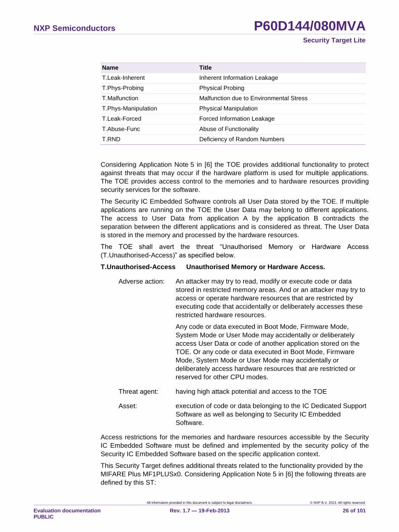
Table 9. Threats defined by the PP [6]
Name Title
NXP Semiconductors P60D144/080MVA Security Target Lite
All information provided in this document is subject to legal disclaimers. © NXP B.V. 2013. All rights reserved.
Evaluation documentation PUBLIC
Rev. 1.7 — 19-Feb-2013 26 of 101
Name Title
T.Leak-Inherent Inherent Information Leakage
T.Phys-Probing Physical Probing
T.Malfunction Malfunction due to Environmental Stress
T.Phys-Manipulation Physical Manipulation
T.Leak-Forced Forced Information Leakage
T.Abuse-Func Abuse of Functionality
T.RND Deficiency of Random Numbers
Considering Application Note 5 in [6] the TOE provides additional functionality to protect
against threats that may occur if the hardware platform is used for multiple applications.
The TOE provides access control to the memories and to hardware resources providing
security services for the software.
The Security IC Embedded Software controls all User Data stored by the TOE. If multiple
applications are running on the TOE the User Data may belong to different applications.
The access to User Data from application A by the application B contradicts the
separation between the different applications and is considered as threat. The User Data
is stored in the memory and processed by the hardware resources.
The TOE shall avert the threat “Unauthorised Memory or Hardware Access
(T.Unauthorised-Access)” as specified below.
T.Unauthorised-Access Unauthorised Memory or Hardware Access.
Adverse action: An attacker may try to read, modify or execute code or data
stored in restricted memory areas. And or an attacker may try to
access or operate hardware resources that are restricted by
executing code that accidentally or deliberately accesses these
restricted hardware resources.
Any code or data executed in Boot Mode, Firmware Mode,
System Mode or User Mode may accidentally or deliberately
access User Data or code of another application stored on the
TOE. Or any code or data executed in Boot Mode, Firmware
Mode, System Mode or User Mode may accidentally or
deliberately access hardware resources that are restricted or
reserved for other CPU modes.
Threat agent: having high attack potential and access to the TOE
Asset: execution of code or data belonging to the IC Dedicated Support
Software as well as belonging to Security IC Embedded
Software.
Access restrictions for the memories and hardware resources accessible by the Security
IC Embedded Software must be defined and implemented by the security policy of the
Security IC Embedded Software based on the specific application context.
This Security Target defines additional threats related to the functionality provided by the
MIFARE Plus MF1PLUSx0. Considering Application Note 5 in [6] the following threats are
defined by this ST:
NXP Semiconductors P60D144/080MVA Security Target Lite
All information provided in this document is subject to legal disclaimers. © NXP B.V. 2013. All rights reserved.
Evaluation documentation PUBLIC
Rev. 1.7 — 19-Feb-2013 27 of 101
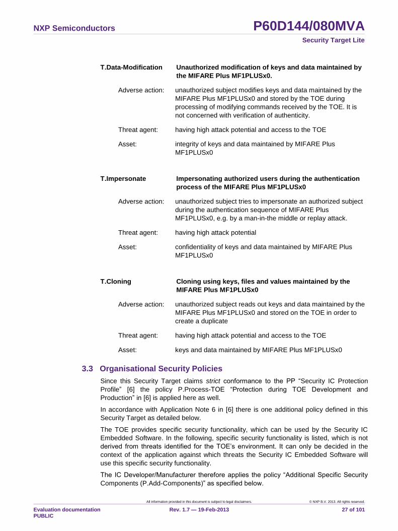
T.Data-Modification Unauthorized modification of keys and data maintained by
the MIFARE Plus MF1PLUSx0.
Adverse action: unauthorized subject modifies keys and data maintained by the
MIFARE Plus MF1PLUSx0 and stored by the TOE during
processing of modifying commands received by the TOE. It is
not concerned with verification of authenticity.
Threat agent: having high attack potential and access to the TOE
Asset: integrity of keys and data maintained by MIFARE Plus
MF1PLUSx0
T.Impersonate Impersonating authorized users during the authentication
process of the MIFARE Plus MF1PLUSx0
Adverse action: unauthorized subject tries to impersonate an authorized subject
during the authentication sequence of MIFARE Plus
MF1PLUSx0, e.g. by a man-in-the middle or replay attack.
Threat agent: having high attack potential
Asset: confidentiality of keys and data maintained by MIFARE Plus
MF1PLUSx0
T.Cloning Cloning using keys, files and values maintained by the
MIFARE Plus MF1PLUSx0
Adverse action: unauthorized subject reads out keys and data maintained by the
MIFARE Plus MF1PLUSx0 and stored on the TOE in order to
create a duplicate
Threat agent: having high attack potential and access to the TOE
Asset: keys and data maintained by MIFARE Plus MF1PLUSx0
3.3 Organisational Security Policies
Since this Security Target claims strict conformance to the PP “Security IC Protection
Profile” [6] the policy P.Process-TOE “Protection during TOE Development and
Production” in [6] is applied here as well.
In accordance with Application Note 6 in [6] there is one additional policy defined in this
Security Target as detailed below.
The TOE provides specific security functionality, which can be used by the Security IC
Embedded Software. In the following, specific security functionality is listed, which is not
derived from threats identified for the TOE‟s environment. It can only be decided in the
context of the application against which threats the Security IC Embedded Software will
use this specific security functionality.
The IC Developer/Manufacturer therefore applies the policy “Additional Specific Security
Components (P.Add-Components)” as specified below.
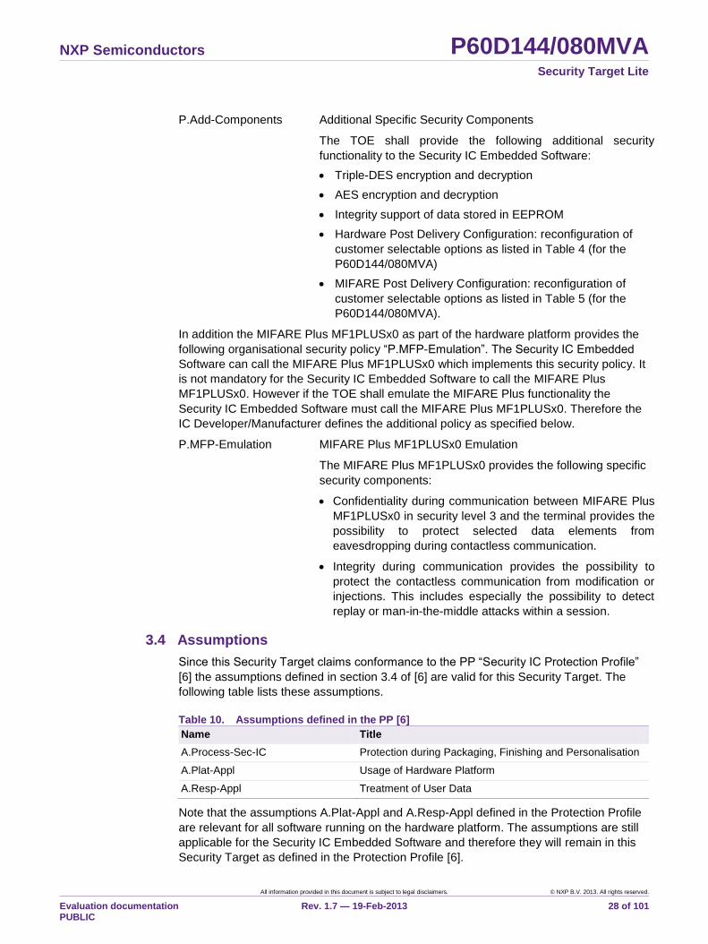
NXP Semiconductors P60D144/080MVA Security Target Lite
All information provided in this document is subject to legal disclaimers. © NXP B.V. 2013. All rights reserved.
Evaluation documentation PUBLIC
Rev. 1.7 — 19-Feb-2013 28 of 101
P.Add-Components Additional Specific Security Components
The TOE shall provide the following additional security
functionality to the Security IC Embedded Software:
Triple-DES encryption and decryption
AES encryption and decryption
Integrity support of data stored in EEPROM
Hardware Post Delivery Configuration: reconfiguration of
customer selectable options as listed in Table 4 (for the
P60D144/080MVA)
MIFARE Post Delivery Configuration: reconfiguration of
customer selectable options as listed in Table 5 (for the
P60D144/080MVA).
In addition the MIFARE Plus MF1PLUSx0 as part of the hardware platform provides the
following organisational security policy “P.MFP-Emulation”. The Security IC Embedded
Software can call the MIFARE Plus MF1PLUSx0 which implements this security policy. It
is not mandatory for the Security IC Embedded Software to call the MIFARE Plus
MF1PLUSx0. However if the TOE shall emulate the MIFARE Plus functionality the
Security IC Embedded Software must call the MIFARE Plus MF1PLUSx0. Therefore the
IC Developer/Manufacturer defines the additional policy as specified below.
P.MFP-Emulation MIFARE Plus MF1PLUSx0 Emulation
The MIFARE Plus MF1PLUSx0 provides the following specific
security components:
Confidentiality during communication between MIFARE Plus
MF1PLUSx0 in security level 3 and the terminal provides the
possibility to protect selected data elements from
eavesdropping during contactless communication.
Integrity during communication provides the possibility to
protect the contactless communication from modification or
injections. This includes especially the possibility to detect
replay or man-in-the-middle attacks within a session.
3.4 Assumptions
Since this Security Target claims conformance to the PP “Security IC Protection Profile”
[6] the assumptions defined in section 3.4 of [6] are valid for this Security Target. The
following table lists these assumptions.
Table 10. Assumptions defined in the PP [6]
Name Title
A.Process-Sec-IC Protection during Packaging, Finishing and Personalisation
A.Plat-Appl Usage of Hardware Platform
A.Resp-Appl Treatment of User Data
Note that the assumptions A.Plat-Appl and A.Resp-Appl defined in the Protection Profile
are relevant for all software running on the hardware platform. The assumptions are still
applicable for the Security IC Embedded Software and therefore they will remain in this
Security Target as defined in the Protection Profile [6].
NXP Semiconductors P60D144/080MVA Security Target Lite
All information provided in this document is subject to legal disclaimers. © NXP B.V. 2013. All rights reserved.
Evaluation documentation PUBLIC
Rev. 1.7 — 19-Feb-2013 29 of 101
The following assumptions are added in this Security Target according to Application
Notes 7 and 8 in [6].
A.Check-Init Check of initialisation data by the Security IC Embedded
Software
The Security IC Embedded Software must provide a function to
check initialisation data. The initialisation data is defined by the
customer. If MIFARE Plus MF1PLUSx0 is enabled the Security
IC Embedded Software must support the use of the originality
key function provided by the MIFARE Plus MF1PLUSx0. The
originality key is defined by NXP. Both data sets are injected by
the TOE Manufacturer into the non-volatile memory to provide
the possibility for TOE identification and for traceability.
The following additional assumption considers specialised encryption hardware of the
TOE.
The developer of the Security IC Embedded Software must ensure the appropriate “Usage
of Key-dependent Functions (A.Key-Function)” while developing this software in Phase 1
as specified below.
A.Key-Function Usage of Key-dependent Functions
Key-dependent functions (if any) shall be implemented in the
Security IC Embedded Software in a way that they are not
susceptible to leakage attacks (as described under T.Leak-
Inherent and T.Leak-Forced).
Note that here the routines which may compromise keys when
being executed are part of the Security IC Embedded Software.
In contrast to this the threats T.Leak-Inherent and T.Leak-
Forced address (i) the cryptographic routines which are part of
the TOE and (ii) the processing of User Data including
cryptographic keys.
The following two assumptions must be implemented to support the security functionality
of the MIFARE Plus MF1PLUSx0.
A.Secure-Values Usage of secure values
Only confidential and secure keys shall be used to set up the
authentication and access rights for the MIFARE Plus
MF1PLUSx0. These values are generated outside the TOE.
They must be protected during generation, management
outside the TOE and downloading to the TOE.
A.Terminal-Support Terminal support to ensure integrity, confidentiality and use of
random numbers
The terminal verifies information sent by the TOE in order to
ensure integrity and confidentiality of the communication.
Furthermore the terminal uses random numbers for the
MIFARE Plus MF1PLUSx0 authentication.
NXP Semiconductors P60D144/080MVA Security Target Lite
All information provided in this document is subject to legal disclaimers. © NXP B.V. 2013. All rights reserved.
Evaluation documentation PUBLIC
Rev. 1.7 — 19-Feb-2013 30 of 101
4. Security Objectives
This chapter contains the following sections: “Security Objectives for the TOE”, “Security
Objectives for the Security IC Embedded Software development Environment”, “Security
Objectives for the Operational Environment” and “Security Objectives Rationale”.
4.1 Security Objectives for the TOE
The TOE shall provide the following security objectives, which are taken from the PP
“Security IC Protection Profile” [6].
Table 11. Security objectives defined in the PP [6]
Name Title
O.Leak-Inherent Protection against Inherent Information Leakage
O.Phys-Probing Protection against Physical Probing
O.Malfunction Protection against Malfunctions
O.Phys-Manipulation Protection against Physical Manipulation
O.Leak-Forced Protection against Forced Information Leakage
O.Abuse-Func Protection against Abuse of Functionality
O.Identification TOE Identification
O.RND Random Numbers
Regarding Application Notes 9 and 10 in [6] the following additional security objectives
are defined based on additional functionality provided by the TOE as specified below.
O.INTEGRITY_CHK Integrity control of transferred data
The TOE shall provide a CRC coprocessor that supports the
integrity protection of user data and TSF data transferred
between different parts of the TOE. This comprises data
transfer between the memories or between a memory and a
hardware component of the TOE.
Note: The integrity control provided by the TOE shall only be
active if explicitly configured by the Security IC Embedded
Software.
O.HW_DES3 Triple DES Functionality
The TOE shall provide the cryptographic functionality to
calculate a Triple DES encryption and decryption to the
Security IC Embedded Software. The TOE supports directly
the calculation of Triple DES with up to three keys.
Note: The TOE will ensure the confidentiality of the User Data
(and especially cryptographic keys) during Triple DES
operation. This is supported by O.Leak-Inherent.
O.HW_AES AES Functionality
The TOE shall provide the cryptographic functionality to
calculate an AES encryption and decryption to the Security IC
Embedded Software. The TOE supports directly the
calculation of AES with three different key lengths.
NXP Semiconductors P60D144/080MVA Security Target Lite
All information provided in this document is subject to legal disclaimers. © NXP B.V. 2013. All rights reserved.
Evaluation documentation PUBLIC
Rev. 1.7 — 19-Feb-2013 31 of 101
Note: The TOE will ensure the confidentiality of the User Data
(and especially cryptographic keys) during AES operation.
This is supported by O.Leak-Inherent.
O.CUST_RECONFIG Post Delivery Configuration
The TOE shall provide the customer with the functionality to
reconfigure parts of the TOE properties as specified for
Hardware Post Delivery Configuration listed in Table 4 and
MIFARE Post Delivery Configuration in Table 5 (for the
P60D144/080MVA).
O.EEPROM_INTEGRITY Integrity support of data stored in EEPROM
The TOE shall provide a retrimming of the EEPROM to
support the integrity of the data stored in the EEPROM.
O.FM_FW Firmware Mode Firewall
The TOE shall provide separation between the NXP Firmware
(i.e. NXP firmware functionality as part of the IC Dedicated
Support Software with MIFARE Plus MF1PLUSx0) as part of
the IC Dedicated Support Software and the Security IC
Embedded Software. The separation shall comprise software
execution and data access.
O.MEM_ACCESS Area based Memory Access Control
Access by processor instructions to memory areas is
controlled by the TOE. The TOE decides based on the CPU
mode (Boot Mode, Test Mode, Firmware Mode, System Mode
or User Mode) and the configuration of the Memory
Management Unit if the requested type of access to the
memory area addressed by the operands in the instruction is
allowed.
O.SFR_ACCESS Special Function Register Access Control
The TOE shall provide access control to the Special Function
Registers depending on the purpose of the Special Function
Register or based on permissions associated to the memory
area from which the CPU is currently executing code. The
access control is used to restrict access to hardware
components of the TOE.
The possibility to define access permissions to specialised
hardware components of the TOE shall be restricted to code
running in System Mode.
The security objectives of the IC Dedicated Support Software (MIFARE Plus
MF1PLUSx0) can only be provided if this IC Dedicated Support Software is called by the
Security IC Embedded Software. The MIFARE Plus MF1PLUSx0 is part of the TOE and
provides the following security objectives:
O.ACCESS-CONTROL Access Control
The TOE must provide an access control mechanism for data
stored by it. The access control mechanism shall apply to all
operations for data elements and to reading and modifying
security attributes as well as authentication data. The
NXP Semiconductors P60D144/080MVA Security Target Lite
All information provided in this document is subject to legal disclaimers. © NXP B.V. 2013. All rights reserved.
Evaluation documentation PUBLIC
Rev. 1.7 — 19-Feb-2013 32 of 101
cryptographic keys used for authentication shall never be
output.
O.AUTHENTICATION Authentication
The TOE must provide an authentication mechanism in order
to be able to authenticate authorised users. The
authentication mechanism shall be resistant against replay
and man-in-the-middle attacks.
O.ENCRYPTION Confidential Communication
The TOE must be able to protect the communication between
the Terminal and MIFARE Plus MF1PLUSx0 by encryption.
This shall be implemented by security attributes that enforce
encrypted communication for the respective data elements.
O.MAC Integrity-protected Communication
The TOE must be able to protect the communication between
the Terminal and MIFARE Plus MF1PLUSx0 by adding a
MAC. This shall be mandatory for commands that modify data
on the TOE and optional on read commands. In addition a
security attribute shall be available to mandate MAC on read
commands, too. Usage of the protected communication shall
also support the detection of injected and bogus commands
within the communication session before the protected data
transfer.
O.TYPE-CONSISTENCY Data type consistency
The TOE must provide a consistent handling of the different
supported data types. This comprises over- and underflow
checking for values and for block sizes.
4.2 Security Objectives for the Security IC Embedded Software development Environment
In addition to the security objectives for the operational environment as required by CC
Part 1 [1] the PP “Security IC Protection Profile” [6] defines security objectives for the
Security IC Embedded Software development environment which are listed in the table
below.
Table 12. Security objectives for the Security IC Embedded Software development
environment, taken from the PP [6]
Security objective Description Applies to phase ...
OE.Plat-Appl Usage of Hardware Platform Phase 1
OE.Resp-Appl Treatment of User Data Phase 1
Clarification of “Usage of Hardware Platform (OE.Plat-Appl)”
The TOE supports cipher schemes as additional specific security functionality. If required
the Security IC Embedded Software shall use these cryptographic services of the TOE
and their interface as specified. When key-dependent functions implemented in the
NXP Semiconductors P60D144/080MVA Security Target Lite
All information provided in this document is subject to legal disclaimers. © NXP B.V. 2013. All rights reserved.
Evaluation documentation PUBLIC
Rev. 1.7 — 19-Feb-2013 33 of 101
Security IC Embedded Software are just being executed, the Security IC Embedded
Software must provide protection against disclosure of confidential data (User Data)
stored and/or processed in the TOE by using the methods described under “Inherent
Information Leakage (T.Leak-Inherent)” and “Forced Information Leakage (T.Leak-
Forced)“.
If the Random Number Generator is used for leakage countermeasures, cryptographic
operations (e.g. key generation) or cryptographic protocols (e.g. challenge-response)
these random numbers must be tested appropriately.
For multi-applications the Security IC Embedded Software (Operating System) can
implement a memory management scheme based upon security functionality of the TOE
to ensure the separation of applications.
Clarification of “Treatment of User Data (OE.Resp-Appl)”
By definition cipher or plain text data and cryptographic keys are User Data. The Security
IC Embedded Software shall treat these data appropriately, use only proper secret keys
(chosen from a large key space) as input for the cryptographic function of the TOE and
use keys and functions appropriately in order to ensure the strength of cryptographic
operation.
This means that keys are treated as confidential as soon as they are generated. The
keys must be unique with a very high probability, as well as cryptographically strong. For
example, if asymmetric algorithms are used, it must be ensured that it is not possible to
derive the private key from a related public key using the attacks defined in this Security
Target. If keys are imported into the TOE and/or derived from other keys, quality and
confidentiality must be maintained. This implies that appropriate key management has to
be realised in the environment.
The treatment of User Data is also required when a multi-application operating system is
implemented as part of the Security IC Embedded Software on the TOE. In this case the
multi-application operating system will not disclose security relevant user data of one
application to another application when it is processed or stored on the TOE.
4.3 Security Objectives for the Operational Environment
The following security objectives for the operational environment are specified according
to the PP “Security IC Protection Profile” [6].
Table 13. Security objectives for the operational environment, taken from the PP [6]
Security objective Description Applies to phase ...
OE.Process-Sec-IC Protection during composite product
manufacturing
TOE delivery up to the end
of phase 6
Check of initialisation data
The TOE provides specific functionality that requires the TOE Manufacturer to implement
measures for the unique identification of the TOE. Therefore, OE.Check-Init is defined to
allow a TOE specific implementation (refer also to A.Check-Init).
OE.Check-Init Check of initialisation data by the Security IC Embedded
Software
To ensure the receipt of the correct TOE, the Security IC
Embedded Software shall check a sufficient part of the pre-
NXP Semiconductors P60D144/080MVA Security Target Lite
All information provided in this document is subject to legal disclaimers. © NXP B.V. 2013. All rights reserved.
Evaluation documentation PUBLIC
Rev. 1.7 — 19-Feb-2013 34 of 101
personalisation data. This shall include at least the FabKey
Data that is agreed between the customer and the TOE
Manufacturer.
OE.Check-OriginalityKey Check of the Originality Key of the MIFARE Plus MF1PLUSx0
To ensure the receipt of the original MIFARE Plus
MF1PLUSx0 functionality, the Security IC Embedded Software
shall support the use of the originality function provided by the
MIFARE Plus MF1PLUSx0. The originality key is introduced
by NXP to check the authenticity of the MIFARE Plus product.
Note: It is not mandatory for the Security IC Embedded Software to use the MIFARE
Plus MF1PLUSx0 or the originality key provided by NXP. The originality
function of MIFARE Plus MF1PLUSx0 is only available when MIFARE Plus
MF1PLUSx0 is enabled.
OE.Secure-Values Generation of secure values
The environment shall generate confidential and secure keys
for authentication purpose of the MIFARE Plus MF1PLUSx0.
These values are generated outside the TOE and they are
downloaded to the TOE during the personalization or usage in
phase 5 to 7.
OE.Terminal-Support Terminal support to ensure integrity, confidentiality and use of
random numbers
The terminal shall verify information sent by the MIFARE Plus
MF1PLUSx0 in order to ensure integrity and confidentiality of
the communication. This involves checking of MAC values,
verification of redundancy information according to the
cryptographic protocol and secure closing of the
communication session.
Furthermore the terminal shall use random numbers with
appropriate entropy for the MIFARE Plus MF1PLUSx0
authentication.
4.4 Security Objectives Rationale
Section 4.4 in the PP “Security IC Protection Profile” [6] provides a rationale how the
assumptions, threats, and organisational security policies are addressed by the
objectives that are specified in the PP [6]. Table 14 reproduces the table in section 4.4 of
[6].
Table 14. Security Objectives versus Assumptions, Threats or Policies (PP)
Assumption, Threat or OSP Security objective Notes
A.Plat-Appl OE.Plat-Appl Phase 1
A.Resp-Appl OE.Resp-Appl Phase 1
P.Process-TOE O.Identification Phases 2 - 3
A.Process-Sec-IC OE.Process-Sec-IC Phases 4 - 6
T.Leak-Inherent O.Leak-Inherent
T.Phys-Probing O.Phys-Probing
T.Malfunction O.Malfunction
NXP Semiconductors P60D144/080MVA Security Target Lite
All information provided in this document is subject to legal disclaimers. © NXP B.V. 2013. All rights reserved.
Evaluation documentation PUBLIC
Rev. 1.7 — 19-Feb-2013 35 of 101
Assumption, Threat or OSP Security objective Notes
T.Phys-Manipulation O.Phys-Manipulation
T.Leak-Forced O.Leak-Forced
T.Abuse-Func O.Abuse-Func
T.RND O.RND
Table 15 provides the justification for the additional security objectives. They are in line
with the security objectives of the PP [6] and supplement these according to the
additional assumptions, threat and organisational security policy.
Table 15. Additional Security Objectives versus Assumptions, Threats or Policies
Assumption/Threat/Policy Security objective Notes
T.Unauthorised-Access O.FM_FW
O.MEM_ACCESS
O.SFR_ACCESS
T.Malfunction O.INTEGRITY_CHK Based on the PP the
security objective
O.Malfunction is
already mapped to this
threat.
P.Add-Components O.HW_DES3
O.HW_AES
O.CUST_RECONFIG
O.EEPROM_INTEGRITY
A.Key-Function OE.Plat-Appl
OE.Resp-Appl
Phase 1
A.Check-Init OE.Check-Init
OE.Check-OriginalityKey
Phase 1 and
Phases 4 - 6
The justification related to the threat “Unauthorised Memory or Hardware Access
(T.Unauthorised-Access)” is as follows:
According to O.FM_FW, O.MEM_ACCESS and O.SFR_ACCESS the TOE must enforce
the partitioning of memory areas in Firmware Mode, System Mode and User Mode and
enforce the segmentation of the memory areas in User Mode so that access of software
to memory areas is controlled. Any restrictions have to be defined by the Security IC
Embedded Software. Thereby security violations caused by accidental or deliberate
access to restricted data (which may include code) can be prevented (refer to
T.Unauthorised-Access). The threat T.Unauthorised-Access is therefore covered by the
objective.
The clarification of “Usage of Hardware Platform (OE.Plat-Appl)” makes clear that it is up
to the Security IC Embedded Software to implement the memory management scheme
by appropriately administrating the TSF. This is also expressed both in T.Unauthorised-
Access and O.FM_FW, O.MEM_ACCESS and O.SFR_ACCESS. The TOE shall provide
access control functions to be used by the Security IC Embedded Software. This is
further emphasised by the clarification of “Treatment of User Data (OE.Resp-Appl)”
which reminds that the Security IC Embedded Software must not undermine the
restrictions of the hardware platform. Therefore, the clarifications contribute to the
coverage of the threat T.Unauthorised-Access.
NXP Semiconductors P60D144/080MVA Security Target Lite
All information provided in this document is subject to legal disclaimers. © NXP B.V. 2013. All rights reserved.
Evaluation documentation PUBLIC
Rev. 1.7 — 19-Feb-2013 36 of 101
The justification related to the threat “Malfunction due to Environmental Stress
(T.Malfunction)” is as follows: Since the objective provides the functionality to check the
integrity of user data and TSF data during the transfer between different parts of the TOE
the objective implements specific security functionality to detect the manipulation of user
data or TSF data. Therefore the threat is countered if the objective holds.
The justification related to the OSP “Additional Specific Security Components
(P.Add-Components)” is as follows: Since the objectives O.HW_DES3, O.HW_AES,
O.CUST_RECONFIG and O.EEPROM_INTEGRITY require the TOE to implement
exactly the same specific security functionality as required by P.Add-Components, the
organisational security policy is covered by the objectives.
Nevertheless the security objectives O.Leak-Inherent, O.Phys-Probing, O.Malfunction,
O.Phys-Manipulation and O.Leak-Forced define how to implement the specific security
functionality required by P.Add-Components. These security objectives are also valid for
the additional specific security functionality since they must avert the related threats also
for the components added related to the policy.
The requirements for a multi-application platform necessitate the separation of users.
Therefore it is volitional that most of the security functionality cannot be influenced or
used in User Mode.
The justification related to the assumption “Usage of Key-dependent Functions
(A.Key-Function)” is as follows:
Compared to [6] a clarification has been made for the security objective “Usage of
Hardware Platform (OE.Plat-Appl)”: If required the Security IC Embedded Software
shall use the cryptographic service of the TOE and its interface as specified. In
addition, the Security IC Embedded Software (i) must implement operations on keys
(if any) in such a manner that they do not disclose information about confidential data
and (ii) must configure the memory management in a way that different applications
are sufficiently separated. If the Security IC Embedded Software uses random
numbers provided by the security service SS.RNG these random numbers must be
tested as appropriate for the intended purpose. This addition ensures that the
assumption A.Key-Function is still covered by the objective OE.Plat-Appl although
additional functions are being supported according to P.Add-Components.
Compared to [6] a clarification has been made for the security objective “Treatment
of User Data (OE.Resp-Appl)”: By definition cipher or plain text data and
cryptographic keys are User Data. So, the Security IC Embedded Software will
protect such data if required and use keys and functions appropriately in order to
ensure the strength of cryptographic operation. Quality and confidentiality must be
maintained for keys that are imported and/or derived from other keys. This implies
that appropriate key management has to be implemented in the environment. In
addition, the treatment of User Data comprises the implementation of a multi-
application operating system that does not disclose security relevant User Data of
one application to another one. These measures make sure that the assumption
A.Key-Function is still covered by the security objective OE.Resp-Appl although
additional functions are being supported according to P.Add-Components.
The justification related to the assumption “Check of initialization data by the Security
IC Embedded Software (A.Check-Init)” is split because the assumption is mapped to
two security objectives for the environment. Both allow an appropriate identification of the
TOE. The justification is as follows:
NXP Semiconductors P60D144/080MVA Security Target Lite
All information provided in this document is subject to legal disclaimers. © NXP B.V. 2013. All rights reserved.
Evaluation documentation PUBLIC
Rev. 1.7 — 19-Feb-2013 37 of 101
Since OE.Check-Init requires the Security IC Embedded Software developer to
implement a function assumed in A.Check-Init, the assumption is covered by the
objective.
OE.Check-OriginalityKey requires the user of the MIFARE Plus MF1PLUSx0 to
check the originality of the TOE as assumed in A.Check-Init. This check is based on
data stored in the EEPROM and defined by NXP.
Both security objectives for the environment are suitable to check the TOE as assumed
in A.Check-Init. Based on the two security objectives for the environment the
administrator of the MIFARE Plus MF1PLUSx0 and the user of the Security IC
Embedded Software are independently able to identify the TOE.
Note: OE.Check-OriginalityKey is only available and required if MIFARE Plus
MF1PLUSx0 is enabled.
Section 4.4 in the PP “Security IC Protection Profile” [6] provides a rationale how the
assumptions, threats, and organisational security policies are addressed by the
objectives that are specified in the PP [6]. Table 16 reproduces the table in section 4.4 of
[6] for MIFARE Plus MF1PLUSx0.
Table 16. Additional Security Objectives versus Assumptions, Threats or Policies (MIFARE
Plus MF1PLUSx0)
Assumption / Threat / Policy Security Objectives Note
A.Secure-Values OE.Secure-Values Phase 7
A.Terminal-Support OE.Terminal-Support Phase 5- 6
T.Data-Modification
O.ACCESS-CONTROL
O.TYPE-CONSISTENCY
OE.Terminal-Support
T.Impersonate O.AUTHENTICATION
OE.Secure-Values
T.Cloning
O.ACCESS-CONTROL
O.AUTHENTICATION
OE.Secure-Values
P.MFP-Emulation
O.ENCRYPTION
O.MAC
OE.Terminal-Support.
The justification related to the assumption “Generation of secure values
(A.Secure_Values)” is as follows:
Since OE.Secure_Values requires using secure values for the configuration of the
authentication and access control as assumed in A.Secure-Values, the assumption is
covered by the objective.
The management of the keys used for the authentication of roles for MIFARE Plus
MF1PLUSx0 must be performed outside the TOE. These keys must be loaded in a
personalisation process and these keys must be protected by the environment. Since
OE.Secure_Values requires from the Administrator, Application Manager or the
Application User to use secure values for the configuration of the authentication and
access control as assumed in A.Secure_Values, the assumption is covered by the
objective.
NXP Semiconductors P60D144/080MVA Security Target Lite
All information provided in this document is subject to legal disclaimers. © NXP B.V. 2013. All rights reserved.
Evaluation documentation PUBLIC
Rev. 1.7 — 19-Feb-2013 38 of 101
The justification related to the assumption “Terminal support to ensure integrity,
confidentiality and use of random numbers (A.Terminal-Support)” is as follows:
The objective OE.Terminal-Support is an immediate transformation of the assumption
A.Terminal-Support, therefore it covers the assumption.
The TOE can only check the integrity of data received from the terminal. For data
transferred to the terminal the receiver must verify the integrity of the received data.
Furthermore the TOE cannot verify the entropy of the random number sent by the
terminal. The terminal itself must ensure that random numbers are generated with
appropriate entropy for the MIFARE Plus MF1PLUSx0 authentication. This is assumed
by the related assumption, therefore the assumption is covered.
The policy “MIFARE Plus MF1PLUSx0 Emulation (P.MFP-Emulation)” is related to the
IC Dedicated Support Software and covers the additional objectives O.ENCRYPTION,
and O.MAC.
The justification of the objectives is as follows: Since these objectives require the TOE to
implement exactly the same specific security functionality as required by P.MFP-
Emulation, the organizational security policy is covered by the objectives. The
functionality of the hardware platform is extended by additional IC Dedicated Support
Software that emulates the security functionality defined by the MIFARE Plus application.
The additional threats T.Data-Modification, T.Impersonate, T.Cloning are related to the
MIFARE Plus application. They supplement the threats defined in the Protection Profile
for the specific application context of MIFARE Plus MF1PLUSx0.
The justification related to the threat “Unauthorised data modification (T.Data-
Modification)” is as follows:
According to threat T.Data-Modification the TOE shall avoid that user data stored by the
TOE may be modified by unauthorised subjects. The objective O.ACCESS-CONTROL
requires an access control mechanism that limits the ability to modify data elements
stored by the TOE. O.TYPE-CONSISTENCY ensures that data types are adhered, so
that data cannot be modified by abusing type-specific operations. The terminal must
provide support by checking the TOE responses, which is required by OE.Terminal-
Support. Therefore T.Data-Modification is covered by these three objectives.
The justification related to the threat “Impersonating authorised users during
authentication (T.Impersonate)” is as follows:
The threat is related to the fact that an unauthorised subject may try to impersonate an
authorised subject during authentication, e.g. by a man-in-the middle or replay attack.
The goal of O. AUTHENTICATION is that an authentication mechanism is implemented
in the TOE that prevents these attacks. Therefore the threat is covered by O.
AUTHENTICATION. This must be supported by OE.Secure-Values because the
authentication is based on keys and the knowledge of the keys must be limited to the
authorized users.
The justification related to the threat “Cloning (T.Cloning)” is as follows:
The concern of T.Cloning is that all data stored on the TOE (including keys) may be read
out in order to create a duplicate. The objectives O. AUTHENTICATION together with
O.ACCESS-CONTROL require that unauthorised users cannot read any information that
is restricted to the authorised subjects. The cryptographic keys used for the
authentication are stored inside the TOE protected by O.ACCESS-CONTROL. This
objective states that the TOE shall never output any keys used for authentication.
NXP Semiconductors P60D144/080MVA Security Target Lite
All information provided in this document is subject to legal disclaimers. © NXP B.V. 2013. All rights reserved.
Evaluation documentation PUBLIC
Rev. 1.7 — 19-Feb-2013 39 of 101
Therefore the two objectives cover T.Cloning. As already mentioned above, an
appropriate key management according to OE.Secure-Values must be ensured.
The justification of the additional threats, policies and assumptions show that they do not
contradict to the rationale already given in the PP [6] for the assumptions, policy and
threats defined there.
5. Extended Components Definition
This Security Target does not define additional extended components.
Note that the PP “Security IC Protection Profile” [6] defines extended security functional
requirements in chapter 5, which are included in this Security Target.
The extended component definition used for Random Number Generator has been taken
from [8].
NXP Semiconductors P60D144/080MVA Security Target Lite
All information provided in this document is subject to legal disclaimers. © NXP B.V. 2013. All rights reserved.
Evaluation documentation PUBLIC
Rev. 1.7 — 19-Feb-2013 40 of 101
6. Security Requirements
This part of the Security Target defines the detailed security requirements that shall be satisfied by the TOE. The statement of TOE security requirements shall define the functional and assurance security requirements that the TOE needs to satisfy in order to meet the security objectives for the TOE. This chapter consists of the sections “Security Functional Requirements”, “Security Assurance Requirements” and “Security Requirements Rationale”.
The CC allows several operations to be performed on security requirements (on the
component level); refinement, selection, assignment, and iteration are defined in
paragraph 8.1 of Part 1 of the CC [1]. These operations are used in the PP [6] and in this
Security Target, respectively.
The refinement operation is used to add details to requirements, and, thus, further
restricts a requirement. Refinements of security requirements are denoted in such a way
that added words are in bold text and changed words are crossed out.
The selection operation is used to select one or more options provided by the PP [6] or
CC in stating a requirement. Selections having been made are denoted as italic text.
The assignment operation is used to assign a specific value to an unspecified
parameter, such as the length of a password. Assignments having been made are
denoted by showing as italic text.
The iteration operation is used when a component is repeated with varying operations. It
is denoted by showing brackets “[iteration indicator]” and the iteration indicator within the
brackets.
For the sake of a better readability, the iteration operation may also be applied to some
single components (being not repeated) in order to indicate belonging of such SFRs to
same functional cluster. In such a case, the iteration operation is applied to only one
single component.
Whenever an element in the PP [6] contains an operation that the PP author left
uncompleted, the ST author has to complete that operation.
6.1 Security Functional Requirements
The Security Functional Requirements (SFRs) of the TOE are presented in the following
sections to support a better understanding of the combination of PP “Security IC
Protection Profile” [6] and Security Target.
6.1.1 SFRs of the Protection Profile
Table 17 below shows all SFRs, which are specified in the PP [6] (in the order of
definition in the PP). Some of the SFRs are CC Part 2 extended and defined in the PP
[6]. This is shown in the third column of the table.
Table 17. SFRs taken from the PP [6]
SFR Title Defined in
FRU_FLT.2 Limited fault tolerance CC, Part 2
FPT_FLS.1 Failure with preservation of secure state CC, Part 2
FMT_LIM.1 Limited capabilities PP, Section 5.2
FMT_LIM.2 Limited availability PP, Section 5.2
FAU_SAS.1 Audit storage PP, Section 5.3
NXP Semiconductors P60D144/080MVA Security Target Lite
All information provided in this document is subject to legal disclaimers. © NXP B.V. 2013. All rights reserved.
Evaluation documentation PUBLIC
Rev. 1.7 — 19-Feb-2013 41 of 101
SFR Title Defined in
FPT_PHP.3 Resistance to physical attack CC, Part 2
FDP_ITT.1 Basic internal transfer protection CC, Part 2
FPT_ITT.1 Basic internal TSF data transfer protection CC, Part 2
FDP_IFC.1 Subset information flow control CC, Part 2
FCS_RNG.1 Random number generation PP, Section 5.1
The definition of the SFRs FDP_ITT.1 and FPT_ITT.1 is repeated in this Security Target
because the selection in each SFR is extended. Based on the Data Processing Policy
defined in PP [6] the SFRs FDP_ITT.1 and FPT_ITT.1 include the additional requirement
to prevent modification of user data and TSF data. The Refinement for the physically
separated parts of the TOE is still valid for both SFRs.
The TOE shall meet the requirement “Basic internal transfer protection (FDP_ITT.1)” as
specified below.
FDP_ITT.1[HW] Basic internal transfer protection
Hierarchical to: No other components.
Dependencies: [FDP_ACC.1 Subset access control, or FDP_IFC.1 Subset
information flow control]
FDP_ITT.1.1[HW] The TSF shall enforce the Data Processing Policy6 to prevent
the disclosure and modification7 of user data when it is
transmitted between physically-separated parts of the TOE.
Refinement: The different memories, the CPU and other functional
units of the TOE (e.g. a cryptographic or CRC co-
processor) are seen as physically-separated parts of the
TOE.
The TOE shall meet the requirement “Basic internal TSF data transfer protection
(FPT_ITT.1)” as specified below.
FPT_ITT.1[HW] Basic internal TSF data transfer protection
Hierarchical to: No other components.
Dependencies: No dependencies.
FPT_ITT.1.1[HW] The TSF shall protect TSF data from disclosure and
modification8 when it is transmitted between separate parts of
the TOE.
Refinement: The different memories, the CPU and other functional
units of the TOE (e.g. a cryptographic or CRC co-
processor) are seen as separated parts of the TOE.
The operations for all other SFR except for the SFR FAU_SAS.1 and FCS_RNG.1 are
already performed in the PP [6]. They are not changed compared to the Protection
Profile. The open assignments and selections for FAU_SAS.1 and FCS_RNG.1 are
included in the following.
6 [assignment: access control SFP(s) and/or information flow control SFP(s)]
7 [selection: disclosure, modification, loss of use]
8 [selection: disclosure, modification]
NXP Semiconductors P60D144/080MVA Security Target Lite
All information provided in this document is subject to legal disclaimers. © NXP B.V. 2013. All rights reserved.
Evaluation documentation PUBLIC
Rev. 1.7 — 19-Feb-2013 42 of 101
For the SFR FAU_SAS.1 the PP [6] leaves the assignment operation open for the non-
volatile memory type in which initialisation data, pre-personalisation data and/or other
supplements for the Security IC Embedded Software are stored. This assignment
operation is filled in by the following statement. Note that the assignment operations for
the list of subjects and the list of audit information have already been filled in by the PP
[6].
FAU_SAS.1[HW] Audit storage
Hierarchical to: No other components.
Dependencies: No dependencies.
FAU_SAS.1.1[HW] The TSF shall provide the test process before TOE Delivery 9
with the capability to store the Initialisation Data and/or Pre-
personalisation Data and/or supplements of the Security IC
Embedded Software 10
in the EEPROM 11
.
For FCS_RNG.1.1 the PP [6] partially fills in the assignment for the security capabilities
of the RNG by requiring a total failure test of the random source and adds an assignment
operation for additional security capabilities of the RNG.
In addition, for FCS_RNG.1.2 the PP [6] partially fills in the assignment operation for the
defined quality metric for the random numbers by replacing it by a selection and
assignment operation.
For the above operations the original operations defined in chapter 5 of the PP [6] have
been replaced by operations defined in chapter 3 of [8] and the open operations of the
partially filled in operations in the statement of the security requirements in section 4.4 of
[8] for better readability. Note that the selection operation for the RNG type has already
been filled in by the PP [6].
FCS_RNG.1[HW] Random number generation (Class PTG.2)
Hierarchical to: No other components.
Note: The definition of the Security Functional Requirement
FCS_RNG.1 has been taken from [8].
Note: The functional requirement FCS_RNG.1[HW] is a refinement
of FCS_RNG.1 defined in PP [6] according to [8].
FCS_RNG.1.1[HW] The TSF shall provide a physical 12
random number generator
that implements:
(PTG.2.1) A total failure test detects a total failure of entropy source
immediately when the RNG has started. When a total failure is
detected, no random numbers will be output.
(PTG.2.2) If a total failure of the entropy source occurs while the RNG is
being operated, the RNG prevents the output of any internal
random number that depends on some raw random numbers
9 [assignment: list of subjects]
10 [assignment: list of audit information]
11 [assignment: type of persistent memory]
12 [selection: physical, non-physical true, deterministic, hybrid physical, hybrid deterministic]
NXP Semiconductors P60D144/080MVA Security Target Lite
All information provided in this document is subject to legal disclaimers. © NXP B.V. 2013. All rights reserved.
Evaluation documentation PUBLIC
Rev. 1.7 — 19-Feb-2013 43 of 101
that have been generated after the total failure of the entropy
source13
.
(PTG.2.3) The online test shall detect non-tolerable statistical defects of
the raw random number sequence (i) immediately when the
RNG has started, and (ii) while the RNG is being operated.
The TSF must not output any random numbers before the
power-up online test has finished successfully or when a
defect has been detected.
(PTG.2.4) The online test procedure shall be effective to detect non-
tolerable weaknesses of the random numbers soon.
(PTG.2.5) The online test procedure checks the quality of the raw
random number sequence. It is triggered at regular intervals
or continuously14
. The online test is suitable for detecting non-
tolerable statistical defects of the statistical properties of the
raw random numbers within an acceptable period of time15
.
Note: The TOE provides the two options where the Embedded
Software can choose one
FCS_RNG.1.2[HW] The TSF shall provide octets of bits
16 that meet:
(PTG.2.6) Test procedure A
17 does not distinguish the internal random
numbers from output sequences of an ideal RNG.
(PTG.2.7) The average Shannon entropy per internal random bit
exceeds 0.99718
Note: The Shannon entropy 0.997 per internal random bit compares
to 7.976 per octet
Note: Application Note 20 in [6] requires that the Security Target
specifies for the security capabilities in FCS_RNG.1.1 how the
results of the total failure test of the random source are
provided to the Security IC Embedded Software. The TOE
features a hardware test which is called by the Security IC
Embedded Software. The results of the internal test sequence
are provided to the Security IC Embedded Software as a pass
or fail criterion by means of a special function register.
13 [selection: prevents the output of any internal random number that depends on some raw random
numbers that have been generated after the total failure of the entropy source, generates the internal
random numbers with a post-processing algorithm of class DRG.2 as long as its internal state
entropy guarantees the claimed output entropy] 14
[selection: externally, at regular intervals, continuously, applied upon specified internal events] 15
[assignment: list of security capabilities] 16
[selection: bits, octets of bits, numbers [assignment: format of the numbers]] 17
[assignment: additional standard test suites] Note: according §295 in [8] the assignment may be
empty 18
[assignment: a defined quality metric]
NXP Semiconductors P60D144/080MVA Security Target Lite
All information provided in this document is subject to legal disclaimers. © NXP B.V. 2013. All rights reserved.
Evaluation documentation PUBLIC
Rev. 1.7 — 19-Feb-2013 44 of 101
The entropy of the random number is measured by the
Shannon-Entropy as follows:
255
0
2logi
ii ppE , where ip is the probability that the
byte ),,,( 067 bbb is equal to i as binary number. Here term
“bit” means measure of the Shannon-Entropy.
The value “7.976” is assigned due to the requirements of
“AIS31”, [7].
Dependencies: No dependencies.
By this, all assignment/selection operations are performed. This Security Target does not
perform any other/further operations than stated in [8].
Considering Application Note 12 of the PP [6] in the following paragraphs the additional
functions for cryptographic support and access control are defined. These SFRs are not
required by the PP [6].
As required by Application Note 14 of the PP [6] the secure state is described in
Section 7.2.2 in the rationale for SF.OPC.
Regarding Application Note 15 of the PP [6] generation of additional audit data is not
defined for “Limited fault tolerance” (FRU_FLT.2) and “Failure with preservation of secure
state” (FPT_FLS.1).
As required by Application Note 18 of the PP [6] the automatic response of the TOE is
described in Section 7.2.2 in the rationale for SF.PHY.
6.1.2 Additional SFRs regarding cryptographic functionality
The (DES coprocessor of the) TOE shall meet the requirement “Cryptographic operation
(FCS_COP.1)” as specified below.
FCS_COP.1[HW_DES] Cryptographic operation
Hierarchical to: No other components.
FCS_COP.1.1[HW_DES] The TSF shall perform encryption and decryption 19
in
accordance with a specified cryptographic algorithm Triple
Data Encryption Algorithm (TDEA) 20
and cryptographic key
sizes of 112 or 168 bit 21
that meet the following list of
standards 22
:
FIPS PUB 46-3 FEDERAL INFORMATION PROCESSING
STANDARDS PUBLICATION DATA ENCRYPTION
STANDARD (DES) Reaffirmed 1999 October 25, keying
options 1 and 2 [20].
Dependencies: [FDP_ITC.1 Import of user data without security attributes or
FDP_ITC.2 Import of user data with security attributes, or
FCS_CKM.1 Cryptographic key generation],
FCS_CKM.4 Cryptographic key destruction.
19 [assignment: list of cryptographic operations]
20 [assignment: cryptographic algorithm]
21 [assignment: cryptographic key sizes]
22 [assignment: list of standards]
NXP Semiconductors P60D144/080MVA Security Target Lite
All information provided in this document is subject to legal disclaimers. © NXP B.V. 2013. All rights reserved.
Evaluation documentation PUBLIC
Rev. 1.7 — 19-Feb-2013 45 of 101
Note: The cryptographic functionality FCS_COP.1[DES] provided by the TOE achieves a
security level of maximum 80 Bits, if keying option 2 is used.
Note: The security functionality is resistant against side channel analysis and similar
techniques. To fend off attackers with high attack potential a security level of at least 80
Bits must be used.
The (AES coprocessor of the) TOE shall meet the requirement “Cryptographic operation
(FCS_COP.1)” as specified below.
FCS_COP.1[HW_AES] Cryptographic operation
Hierarchical to: No other components.
FCS_COP.1.1[HW_AES] The TSF shall perform encryption and decryption 23
in
accordance with a specified cryptographic algorithm
Advanced Encryption Standard (AES) algorithm 24
and
cryptographic key sizes of 128, 192 or 256 bit 25
that meet the
following list of standards 26
:
FIPS PUB 197 FEDERAL INFORMATION PROCESSING
STANDARDS PUBLICATION, ADVANCED ENCRYPTION
STANDARD (AES), National Institute of Standards and
Technology, 2001 November 26 [21].
Dependencies: [FDP_ITC.1 Import of user data without security attributes or
FDP_ITC.2 Import of user data with security attributes, or
FCS_CKM.1 Cryptographic key generation],
FCS_CKM.4 Cryptographic key destruction.
The (EEPROM adjustment operation) TOE shall meet the requirement “Stored data
integrity monitoring and action (FDP_SDI.2)” as specified below.
FDP_SDI.2[HW] Stored data integrity monitoring and action
Hierarchical to: FDP_SDI.1 Stored data integrity monitoring
FDP_SDI.2.1[HW] The TSF shall monitor user data stored in containers
controlled by the TSF for integrity violations due to ageing 27
on all objects, based on the following attributes: User data
including code stored in the EEPROM 28
.
FDP_SDI.2.2[HW] Upon detection of a data integrity error, the TSF shall adjust
the EEPROM write operation. 29
.
Dependencies: No dependencies.
Refinement: Each EEPROM memory block is considered as one
container and the adjustment is done for one complete
EEPROM memory block.
23 [assignment: list of cryptographic operations]
24 [assignment: cryptographic algorithm]
25 [assignment: cryptographic key sizes]
26 [assignment: list of standards]
27 [assignment: integrity errors]
28 [assignment: user data attributes]
29 [assignment: action to be taken]
NXP Semiconductors P60D144/080MVA Security Target Lite
All information provided in this document is subject to legal disclaimers. © NXP B.V. 2013. All rights reserved.
Evaluation documentation PUBLIC
Rev. 1.7 — 19-Feb-2013 46 of 101
6.1.3 Additional SFRs regarding access control
Access Control Policy
The hardware shall provide different CPU modes to IC Dedicated Support Software and
Security IC Embedded Software for separating the code and data of these two domains.
The separation shall be supported by the partitioning of memories. Management of
access to code and data as well as access to hardware resources shall be assigned to
dedicated CPU modes. The hardware shall enforce separation between different
applications (i.e. parts of the Security IC Embedded Software) running on the TOE. The
TOE shall support this based on the CPU modes and the segmentation of the memories.
The TOE shall support secure operation on Special Function Register depending on
register functionality or on the CPU mode. In addition an application shall not be able to
access hardware components unless permission is granted explicitly. The hardware shall
provide direct memory access for the Security IC Embedded Software without CPU
interactions realized by copy machines. The copy machines shall support different CPU
modes and the segmentation of the memories.
The Security Function Policy (SFP) Access Control Policy uses the following definitions.
The subjects are
The Security IC Embedded Software i.e. data in the memories of the TOE executed
as instructions by the CPU
The Test-ROM Software as IC Dedicated Test Software, executed as instructions by
the CPU
The Boot-ROM Software as part of the IC Dedicated Support Software, executed as
instructions by the CPU
The Firmware Operating System as part of the IC Dedicated Support Software
including the resource configuration firmware executed as instructions by the CPU
and stored data integrity monitoring for EEPROM write accesses of the Security IC
Embedded Software.
The Firmware Firewall configured by the IC Dedicated Support Software for
restricted access of the Firmware Operating System to the hardware related Special
Function Registers and separation between IC Dedicated Support Software and
Security IC Embedded Software
The copy machines configured by the Security IC Embedded Software for direct
memory access enforcing separation between different CPU modes and the
segmentation of memories
The Fame2 coprocessor configured by the Security IC Embedded Software for
implementation of asymmetric cryptographic algorithms and direct memory access to
the FXRAM for accessing operands and storing resulting data.
The objects are
the memories consisting of
ROM, which is partitioned into Test-ROM and Application-ROM
EEPROM, which is partitioned into two parts. To simplify referencing, the part
reserved for the Firmware Operating System is called Firmware-EEPROM, the
other part Application-EEPROM.
RAM, which is partitioned into two parts. To simplify referencing, the part reserved
for the Firmware Operating System is called Firmware-RAM, the other part
Application-RAM.
NXP Semiconductors P60D144/080MVA Security Target Lite
All information provided in this document is subject to legal disclaimers. © NXP B.V. 2013. All rights reserved.
Evaluation documentation PUBLIC
Rev. 1.7 — 19-Feb-2013 47 of 101
The code and data in the Memory Segments defined by the Memory Management
Unit in Application-ROM, Application-EEPROM and Application-RAM. Note that
this memory is a subset of the first three.
The physical memory locations within the three memories that are used by the
Memory Management Unit for the MMU Segment Table.
The virtual memory locations within the three memories that are used by the CPU
and are mapped to physical addresses by the Memory Management Unit.
The Special Function Registers consisting of
Special Function Registers to configure the MMU segmentation. This group
contains the registers that define the pointer to the MMU Segment Table.
Special Function Registers related to system management, a number of Special
Function Registers that are intended to be used for overall system management
by the operating system.
Special Function Registers to configure the Firmware firewall. These Special
Function Registers allow modifying the Firmware firewall regarding data exchange
and Special Function Register access control.
Special Function Registers used by the Firmware Operating System including the
resource configuration firmware. The Firmware Operating System uses a number
of internal Special Function Registers.
Special Function Registers related to testing. These Special Function Registers
are reserved for testing purposes.
Special Function Registers related to hardware components. These Special
Function Registers are used to utilise hardware components like the coprocessors
or the interrupt system.
Special Function Registers related to general CPU functionality. This group
contains e.g. the accumulator, stack pointer and data pointers.
o Special Function Registers related to general CPU functionality are
implemented separately for System and User Mode. This group contains CPU
watch exception register for System and User Mode.
The Firmware Firewall configured during bootflow that separates memories of
Firmware Operating System from Security IC Embedded Software.
The memory operations are
read data from the memory,
write data into the memory and
execute data stored in the memory.
The Special Function Register operations are
read data from a Special Function Register and
write data into a Special Function Register.
The security attributes are
CPU mode: There are five CPU modes that are sequentially active based on the
configuration of Special Function Registers defining whether the instruction is
executed in Boot Mode, Test Mode, Firmware Mode, System Mode or User Mode.
NXP Semiconductors P60D144/080MVA Security Target Lite
All information provided in this document is subject to legal disclaimers. © NXP B.V. 2013. All rights reserved.
Evaluation documentation PUBLIC
Rev. 1.7 — 19-Feb-2013 48 of 101
The values of the Special Function Registers to configure the MMU segmentation
and Special Function Registers related to system management. These groups
contain the pointer to the MMU Segment Table and those relevant for the overall
system management of the TOE.
MMU Segment Table: Configuration of the Memory Segments comprising access
rights (read, write and execute), the virtual code memory base address of the first
and last valid address, and the relocation offset of the physical memory location for
each of the 64 possible Memory Segments. For every segment also the access
rights to the Special Function Registers related to hardware components are defined.
The values of the Special Function Registers MMU_FWCTRLL, MMU_FWCTRLH,
MMU_MXBASL, MMU_MXBASH, MMU_MXSZL and MMU_MXSZH belonging to the
group Special Function Registers related to hardware components that define the
access rights to the Special Function Registers related to hardware components for
code executed in Firmware Mode and the RAM area used for data exchange
between IC Dedicated Support Software (Firmware Operating System including
resource configuration firmware) and Security IC Embedded Software.
In the following the term “code running” combined with a CPU mode (e.g. “code running
in System Mode”) is used to name subjects.
Note: Use of a Memory Segment is disabled in case no access permissions are
granted. It is not necessary to define all 64 possible Memory Segments, the
Memory Management Unit is capable of managing an arbitrary number of
segments up to the limit of 64.
The TOE shall meet the requirements “Subset access control (FDP_ACC.1)” as specified
below.
FDP_ACC.1[MEM] Subset access control
Hierarchical to: No other components.
FDP_ACC.1.1[MEM] The TSF shall enforce the Access Control Policy 30
on all code
running on the TOE, all memories and all memory
operations 31
.
Dependencies: FDP_ACF.1 Security attribute based access control
Application Note: The Access Control Policy shall be enforced by implementing
a Memory Management Unit, which maps virtual addresses to
physical addresses. The CPU always uses virtual addresses,
which are mapped to physical addresses by the Memory
Management Unit. Prior to accessing the respective memory
address, the Memory Management Unit checks if the access
is allowed.
FDP_ACC.1[SFR] Subset access control
Hierarchical to: No other components.
FDP_ACC.1.1[SFR] The TSF shall enforce the Access Control Policy 32
on all code
running on the TOE, all Special Function Registers, and all
Special Function Register operations 33
.
30 [assignment: access control SFP]
31 [assignment: list of subjects, objects, and operations among subjects and objects covered by the
SFP] 32
[assignment: access control SFP]
NXP Semiconductors P60D144/080MVA Security Target Lite
All information provided in this document is subject to legal disclaimers. © NXP B.V. 2013. All rights reserved.
Evaluation documentation PUBLIC
Rev. 1.7 — 19-Feb-2013 49 of 101
Dependencies: FDP_ACF.1 Security attribute based access control
Application Note: The Access Control Policy shall be enforced by implementing
hardware access control to each Special Function Register.
For every access the CPU mode is used to determine if the
access shall be granted or denied. In addition, in User Mode
and Firmware Mode the access rights to the Special Function
Registers related to hardware components are provided by
the MMU Segment Table and the Special Function Registers
to configure the Firmware firewall. A denied read or write
access triggers an exception. The read and/or write access to
a Special Function Register may be not allowed depending on
the function of the register or on the CPU mode to enforce the
access control policy or ensure a secure operation.
The TOE shall meet the requirement “Security attribute based access control
(FDP_ACF.1)” as specified below.
FDP_ACF.1[MEM] Security attribute based access control
Hierarchical to: No other components.
FDP_ACF.1.1[MEM] The TSF shall enforce the Access Control Policy 34
to objects
based on the following: all subjects and objects and the
attributes CPU mode, the MMU Segment Table, the Special
Function Registers to configure the MMU segmentation and
the Special Function Registers related to system
management 35
.
FDP_ACF.1.2[MEM] The TSF shall enforce the following rules to determine if an
operation among controlled subjects and controlled objects is
allowed:
Code executed in the Boot Mode
has read and execute access to all code/data in the Test-
ROM,
has read, write and execute access to all code/data in the
Firmware-EEPROM
has read and write access to all data in the Firmware-RAM
Code executed in the Test Mode
has read and execute access to all code/data in the whole
ROM,
has read, write and execute access to all code/data in the
whole EEPROM
has read and write access to all data in the whole RAM
Code executed in the Firmware Mode
33
[assignment: list of subjects, objects, and operations among subjects and objects covered by the
SFP] 34
[assignment: access control SFP] 35
[assignment: list of subjects and objects controlled under the indicated SFP, and for each, the SFP-
relevant security attributes, or named groups of SFP-relevant security attributes]
NXP Semiconductors P60D144/080MVA Security Target Lite
All information provided in this document is subject to legal disclaimers. © NXP B.V. 2013. All rights reserved.
Evaluation documentation PUBLIC
Rev. 1.7 — 19-Feb-2013 50 of 101
has read and execute access to its own code/data in the
Firmware-ROM,
has read and write access to all code/data in the whole
EEPROM for data integrity control during EEPROM write
operations and read, write and execute access to the
Firmware EEPROM for other purpose controlled by the
Firmware Firewall,
has read and write access to all data in the Firmware-RAM
Code executed in the System Mode
has read and execute access to all code/data in the
Application-ROM
has read, write and execute access to all code/data in the
Application-EEPROM,
has read and write access to all data in the Application-
RAM
Code executed in the User Mode
has read and/or execute access to code/data in the
Application-ROM controlled by the MMU Segment Table
used by the Memory Management Unit,
has read and/or write and/or execute access to code/data
in the Application-EEPROM controlled by the MMU
Segment Table used by the Memory Management Unit,
has read and/or write access to data in the Application-
RAM controlled by the MMU Segment Table used by the
Memory Management Unit. 36
FDP_ACF.1.3[MEM] The TSF shall explicitly authorise access of subjects to objects
based on the following additional rules: Code running in
Firmware Mode has access to the Application-RAM defined by
the Special Function Register MMU_MXBASL,
MMU_MXBASH, MMU_MXSZL and MMU_MXSZH. Code
running in Boot Mode or Firmware Mode has read access to
the Security Rows stored in the Application-EEPROM. Code
running in Firmware Mode when called from System Mode
has read and write access to the Application-EEPROM for
data integrity control reasons during EEPROM write
operations. The Fame2 coprocessor has read/write access to
the FXRAM. 37
FDP_ACF.1.4[MEM] The TSF shall explicitly deny access of subjects to objects
based on the following additional rules: if configured code
executed in EEPROM cannot read ROM, if configured the
copy machine cannot read ROM, if configured the copy
machine cannot read EEPROM 38
.
36 [assignment: rules governing access among controlled subjects and controlled objects using
controlled operations on controlled objects] 37
[assignment: rules, based on security attributes, that explicitly authorise access of subjects to objects] 38
[assignment: rules, based on security attributes, that explicitly deny access of subjects to objects]
NXP Semiconductors P60D144/080MVA Security Target Lite
All information provided in this document is subject to legal disclaimers. © NXP B.V. 2013. All rights reserved.
Evaluation documentation PUBLIC
Rev. 1.7 — 19-Feb-2013 51 of 101
Dependencies: FDP_ACC.1 Subset access control FMT_MSA.3 Static
attribute initialisation
FDP_ACF.1[SFR] Security attribute based access control
Hierarchical to: No other components.
FDP_ACF.1.1[SFR] The TSF shall enforce the Access Control Policy 39
to objects
based on the following: all subjects and objects and the
attributes CPU mode, the MMU Segment Table and the
Special Function Registers MMU_FWCTRLL and
MMU_FWCTRLH 40
.”
FDP_ACF.1.2[SFR] The TSF shall enforce the following rules to determine if an
operation among controlled subjects and controlled objects is
allowed:
The code executed in Boot Mode is allowed to access all
Special Function Register groups except Special Function
Registers related to testing, Special Function Registers to
configure the MMU segmentation and Special Function
Registers related to general CPU functionality implemented
separately for System and User Mode.
The code executed in Test Mode is allowed to access all
Special Function Register groups except Special Function
Registers to configure the MMU segmentation and Special
Function Registers related to general CPU functionality
implemented separately for System and User Mode.
The code executed in Firmware Mode is allowed to read
Special Function Registers to configure the Firmware
firewall and to read/write Special Function Registers used
by the Firmware Operating System and the resource
configuration firmware. Access to Special Function
Registers related to hardware components is based on the
access rights determined by the Special Function Registers
MMU_FWCTRLL and MMU_FWCTRLH.
The code executed in System Mode is allowed to access
Special Function Registers to configure the MMU
segmentation, Special Function Registers related to system
management, Special Function Registers to configure the
Firmware firewall and Special Function Registers related to
hardware components.
The code executed in the User Mode is allowed to access
Special Function Registers related to hardware
components based on the access rights defined in the
respective Memory Segment in the MMU Segment Table
from which the code is actually executed 41
.
39 [assignment: access control SFP]
40 [assignment: list of subjects and objects controlled under the indicated SFP, and for each, the SFP-
relevant security attributes, or named groups of SFP-relevant security attributes] 41
[assignment: rules governing access among controlled subjects and controlled objects using
controlled operations on controlled objects]
NXP Semiconductors P60D144/080MVA Security Target Lite
All information provided in this document is subject to legal disclaimers. © NXP B.V. 2013. All rights reserved.
Evaluation documentation PUBLIC
Rev. 1.7 — 19-Feb-2013 52 of 101
Application Note: Copy Machines continue operation in the CPU mode in which
they have been started independent of any CPU mode
changes initiated by the Security IC Embedded Software
during copy machine operation.
FDP_ACF.1.3[SFR] The TSF shall explicitly authorise access of subjects to objects
based on the following additional rules: In any CPU mode
access to the Special Function Registers related to general
CPU functionality, except those implemented separately for
System and User Mode, is allowed. In System and User Mode
access to the Special Function Registers related to general
CPU functionality implemented separately for System and
User Mode is allowed. The Special Function Register
CPU_CSR belonging to group Special Function Registers
related to system management is additionally readable in
Firmware Mode and User Mode. The Special Function
Register CFG_CLKSEL of the group Special Function
Registers related to hardware components can be read in the
Firmware Mode regardless of the Firmware firewall settings
given by MMU_FWCTRLL and MMU_FWCTRLH. 42
FDP_ACF.1.4[SFR] The TSF shall explicitly deny access of subjects to objects
based on the following additional rules: Access to Special
Function Registers to configure the MMU segmentation is
denied in all CPU modes except System Mode. Access to
Special Function Registers related to general CPU
functionality implemented separately for System and User
Mode is denied in Boot, Test and Firmware Mode. The
Special Function Register MMU_RPT2 of the group Special
Function Registers related to system management is not
readable. The Special Function Register RNG_RNR of the
group Special Function Registers related to hardware
components is read-only. The Special Function Registers
SBC_KEY used as key registers for AES and DES
coprocessors of the group Special Function Registers related
to hardware components are not readable. 43
Dependencies: FDP_ACC.1 Subset access control
FMT_MSA.3 Static attribute initialisation
Implications of the Access Control Policy
The Access Control Policy has some implications, that can be drawn from the policy and
that are essential parts of the TOE security functionality.
Code executed in Boot Mode or Test Mode is quite powerful and used to configure
and test the TOE.
Code executed in Firmware Mode is separated from code executed in System Mode
or User Mode. The separation is enforced by the partition of the memories provided
by the Memory Management Unit. Only small memory areas are used for data
exchange between the Firmware Operating System and the Security IC Embedded
Software. Furthermore, the exchange area in RAM is fully controlled by code running
42 [assignment: rules, based on security attributes, that explicitly authorise access of subjects to objects]
43 [assignment: rules, based on security attributes, that explicitly deny access of subjects to objects]
NXP Semiconductors P60D144/080MVA Security Target Lite
All information provided in this document is subject to legal disclaimers. © NXP B.V. 2013. All rights reserved.
Evaluation documentation PUBLIC
Rev. 1.7 — 19-Feb-2013 53 of 101
in System Mode. The EEPROM data integrity function executed in Firmware Mode
has access to the whole EEPROM area to guarantee data integrity for EEPROM
write operations. MIFARE Plus MF1PLUSx0 only has access to a separated
dedicated area in the EEPROM. Separation is realized by means of a Firmware
Firewall.
Code executed in the System Mode can administrate the configuration of Memory
Management Unit, because it has access to the respective Special Function
Registers. Configuration means that the code can change the address of the MMU
Segment Table and also modify the contents of it (as long as the table is located in
write-able memory).
Code executed in the User Mode cannot administrate the configuration of the
Memory Management Unit, because it has no access to the Special Function
Registers to configure the MMU segmentation. Therefore changing the pointer to the
MMU Segment Table is not possible.
It may be possible for User Mode code to modify the MMU Segment Table contents if
the table itself is residing in a memory location that is part of a Memory Segment that
the code has write access to.
The TOE shall meet the requirement “Static attribute initialisation (FMT_MSA.3)” as
specified below.
FMT_MSA.3[MEM] Static attribute initialisation
Hierarchical to: No other components.
FMT_MSA.3.1[MEM] The TSF shall enforce the Access Control Policy 44
to provide
restrictive 45
default values for security attributes that are used
to enforce the SFP.
FMT_MSA.3.2[MEM] The TSF shall allow the no subject 46
to specify alternative
initial values to override the default values when an object or
information is created.
Dependencies: FMT_MSA.1 Management of security attributes
FMT_SMR.1 Security roles
Application Note: Restrictive means here that the reset values of the Special
Function Register regarding the address of the MMU Segment
Table are set to zero, which effectively disables any memory
segment so that no User Mode code can be executed by the
CPU. Furthermore, the memory partition cannot be configured
at all.
The TOE does not provide objects or information that can be
created, since it provides access to memory areas. The
definition of objects that are stored in the TOE‟s memory is
subject to the Security IC Embedded Software.
FMT_MSA.3[SFR] Static attribute initialisation
Hierarchical to: No other components.
44 [assignment: access control SFP, information flow control SFP]
45 [selection: choose one of: restrictive, permissive, [assignment: other property]]
46 [assignment: the authorised identified roles]
NXP Semiconductors P60D144/080MVA Security Target Lite
All information provided in this document is subject to legal disclaimers. © NXP B.V. 2013. All rights reserved.
Evaluation documentation PUBLIC
Rev. 1.7 — 19-Feb-2013 54 of 101
FMT_MSA.3.1[SFR] The TSF shall enforce the Access Control Policy 47
to provide
restrictive 48
default values for security attributes that are used
to enforce the SFP.
FMT_MSA.3.2[SFR] The TSF shall allow the no subject 49
to specify alternative
initial values to override the default values when an object or
information is created.
Dependencies: FMT_MSA.1 Management of security attributes
FMT_SMR.1 Security roles
Application Note: The TOE does not provide objects or information that can be
created since no further security attributes can be derived (i.e.
the set of Special Function Registers that contain security
attributes is fixed). The definition of objects that are stored in
the TOE‟s memory is subject to the Security IC Embedded
Software.
The TOE shall meet the requirement “Management of security attributes (FMT_MSA.1)”
as specified below.
FMT_MSA.1[MEM] Management of security attributes
Hierarchical to: No other components.
FMT_MSA.1.1[MEM] The TSF shall enforce the Access Control Policy 50
to restrict
the ability to modify 51
the security attributes Special Function
Registers to configure the MMU segmentation 52
to code
executed in the System Mode 53
.
Dependencies: [FDP_ACC.1 Subset access control or
FDP_IFC.1 Subset information flow control]
FMT_SMR.1 Security roles
FMT_SMF.1 Specification of Management Functions
Application Note: The MMU Segment Table is not included in this requirement
because it is located in the memory of the TOE and access to
it is possible for every role that has access to the respective
memory locations.
This component does not include any management
functionality for the configuration of the memory partition. This
is because the memory partition is fixed and cannot be
changed after TOE delivery.
FMT_MSA.1[SFR] Management of security attributes
Hierarchical to: No other components.
FMT_MSA.1.1[SFR] The TSF shall enforce the Access Control Policy 54
to restrict
the ability to modify 55
the security attributes defined in Special
47 [assignment: access control SFP, information flow control SFP]
48 [selection: choose one of: restrictive, permissive, [assignment: other property]]
49 [assignment: the authorised identified roles]
50 [assignment: access control SFP(s), information flow control SFP(s)]
51 [selection: change_default, query, modify, delete, [assignment: other operations]]
52 [assignment: list of security attributes]
53 [assignment: the authorised identified roles]
54 [assignment: access control SFP(s), information flow control SFP(s)]
NXP Semiconductors P60D144/080MVA Security Target Lite
All information provided in this document is subject to legal disclaimers. © NXP B.V. 2013. All rights reserved.
Evaluation documentation PUBLIC
Rev. 1.7 — 19-Feb-2013 55 of 101
Function Registers 56
to code executed in a CPU mode which
has write access to the respective Special Function
Registers 57
.
Dependencies: [FDP_ACC.1 Subset access control or
FDP_IFC.1 Subset information flow control]
FMT_SMR.1 Security roles
FMT_SMF.1 Specification of Management Functions
The TOE shall meet the requirement “Specification of Management Functions
(FMT_SMF.1)” as specified below.
FMT_SMF.1[HW] Specification of Management Functions
Hierarchical to: No other components.
FMT_SMF.1.1[HW] The TSF shall be capable of performing the following
management functions:
Change of the CPU mode by calling a system call vector
(SVEC) or firmware vector (FVEC) address,
change of the CPU mode by invoking an exception or
interrupt,
change of the CPU mode by finishing an exception/interrupt
(with a RETI instruction),
change of the CPU mode with a special
LCALL/ACALL/ECALL address,
change of the CPU mode by writing to the respective bits in
the CPU_CSR Special Function Register and
modification of the Special Function Registers containing
security attributes, and
modification of the MMU Segment Table, and
temporary disabling and enabling of the security functionality
EEPROM Size, CXRAM Size, AES coprocessor, Fame2
coprocessor and
permanent disabling and enabling of the security functionality
EEPROM Size, CXRAM Size, AES coprocessor, Fame2
coprocessor
permanent disabling and enabling of the security functionality
MIFARE Plus MF1PLUSx0 and MIFARE Plus MF1PLUSx0
EEPROM size58
.
Dependencies: No dependencies
Application Note: The iteration of FMT_MSA.1 with the dependency to
FMT_SMF.1[HW] may imply a separation of the Specification
of Management Functions. All management functions rely on
the same features implemented in the hardware.
55
[selection: change_default, query, modify, delete, [assignment: other operations]] 56
[assignment: list of security attributes] 57
[assignment: the authorised identified roles] 58
[assignment: list of management functions to be provided by the TSF]
NXP Semiconductors P60D144/080MVA Security Target Lite
All information provided in this document is subject to legal disclaimers. © NXP B.V. 2013. All rights reserved.
Evaluation documentation PUBLIC
Rev. 1.7 — 19-Feb-2013 56 of 101
6.1.4 Additional SFRs for the MIFARE Plus MF1PLUSx0
MIFARE Plus MF1PLUSx0 Access Control Policy
The Security Function Policy (SFP) MFP Access Control Policy uses the following
definitions:
The following roles are supported:
The Personaliser who can personalise the TOE in security level 0.
The Card Administrator who can change security attributes which cannot be
changed in the field.
The Card Manager who can change security attributes in the field.
The Card Security Level Manager who can switch the card to a higher security
level.
The Card User who can perform operations with blocks.
The Originality Key User who can authenticate himself to prove the authenticity of
the Card.
Note that multiple subjects may have the same role, e.g. for every sector there are two
Card Users (identified by the respective “Key A” and “Key B” for this sector). The
assigned rights to the Card Users can be different, which allows having more or less
powerful Card Users. There are also more than one Originality Key User and Card
Security Level Manager.
Any other subject belongs to the role Anybody which is not modelled explicitly in the
policy because no access rights are granted to this role. This role includes the card
holder (i.e. end-user) and any other subject e.g. an attacker.
The objects are
blocks that are grouped in sectors. Each sector consists of either 4 or 16 blocks.
One block of each sector contains the access conditions and is called sector trailer.
One specific type of data stored in a block is a value.
The operations that can be performed with the objects are
read data from a block,
write data to a block and
increase, decrease, transfer or restore a value
The operations that can be performed with the security attributes are
read the security attributes or
modify the security attributes.
The security attributes are (see [15] for further details)
the MFP Configuration Block,
the Field Configuration Block,
the sector trailer for a sector and
the security level of the TOE.
Note that subjects are authorised by cryptographic keys by using the authenticate
operation. These keys are considered as authentication data and not as security
attributes. The TOE stores a dedicated cryptographic key for every subject. The key of
the Card Administrator is called “Card Master Key” and the key for the Card Manager is
NXP Semiconductors P60D144/080MVA Security Target Lite
All information provided in this document is subject to legal disclaimers. © NXP B.V. 2013. All rights reserved.
Evaluation documentation PUBLIC
Rev. 1.7 — 19-Feb-2013 57 of 101
called “Card Configuration Key”. The Card Security Level Manager keys are called “Level
2 Switch Key” and “Level 3 Switch Key”. The keys of the Card Users are called “AES
Sector Keys”. Since there are two keys for every sector the keys are called “AES Sector
Key A” and “AES Sector Key B” or in short “Key A” and “Key B”. The keys of the
Originality Key User are called “Originality Keys”.
The TOE shall meet the requirements “Security roles (FMT_SMR.1)” as specified below.
FDP_ACC.1[MFP] Subset access control
Hierarchical to: No other components.
FDP_ACC.1.1[MFP] The TSF shall enforce the MFP Access Control Policy 59
on all
subjects, objects, operations and security attributes defined by
the MFP Access Control Policy 60
.
Dependencies: FDP_ACF.1 Security attribute based access control
The TOE shall meet the requirement “Security attribute based access control
(FDP_ACF.1)” as specified below.
FDP_ACF.1[MFP] Security attribute based access control
Hierarchical to: No other components.
FDP_ACF.1.1[MFP] The TSF shall enforce the MFP Access Control Policy 61
to
objects based on the following: all subjects, objects and
security attributes 62
.
FDP_ACF.1.2[MFP] The TSF shall enforce the following rules to determine if an
operation among controlled subjects and controlled objects is
allowed:
The Personaliser can change all blocks.
For every sector the Card User can read or write a data
block; read, increase, decrease, transfer or restore a value
based on the access control settings in the respective
sector trailer 63
.
FDP_ACF.1.3[MFP] The TSF shall explicitly authorise access of subjects to objects
based on the following additional rules: none 64
.
FDP_ACF.1.4[MFP] The TSF shall explicitly deny access of subjects to objects
based on the following additional rules:
The block 0 (first block of the first sector) cannot be
modified 65
.
Dependencies: FDP_ACC.1 Subset access control
FMT_MSA.3 Static attribute initialisation
59 [assignment: access control SFP]
60 [assignment: list of subjects, objects, and operations among subjects and objects covered by the
SFP] 61
[assignment: access control SFP] 62
[assignment: list of subjects and objects controlled under the indicated SFP, and for each, the SFP-
relevant security attributes, or named groups of SFP-relevant security attributes] 63
[assignment: rules governing access among controlled subjects and controlled objects using
controlled operations on controlled objects] 64
[assignment: rules, based on security attributes, that explicitly authorise access of subjects to objects] 65
[assignment: rules, based on security attributes, that explicitly deny access of subjects to objects]
NXP Semiconductors P60D144/080MVA Security Target Lite
All information provided in this document is subject to legal disclaimers. © NXP B.V. 2013. All rights reserved.
Evaluation documentation PUBLIC
Rev. 1.7 — 19-Feb-2013 58 of 101
The TOE shall meet the requirement “Static attribute initialisation (FMT_MSA.3)” as
specified below.
Implications of the MFP Access Control Policy
The MFP Access Control Policy has some implications, that can be drawn from the policy
and that are essential parts of the TOE security functions.
The TOE end-user does normally not belong to the group of authorised users
(Personaliser, Card Administrator, Card Manager, Card Security Level Manager,
Card User, Originality Key User), but is regarded as „Anybody‟ by the TOE. This
means that the TOE cannot determine if it is used by its intended end-user (in other
words: it cannot determine if the current card holder is the owner of the card).
The Personaliser is very powerful, although the role is limited to Security Level 0.
The Personaliser can write all blocks and therefore change all data and the sector
trailers.
Switching of the security level is an integral part of the TOE security. The TOE is
switched from security level 0 to security level 1 or 3 at the end of the personalisation
phase. The security level can be increased by the Card Security Level Manager
afterwards.
FMT_MSA.3[MFP] Static attribute initialisation
Hierarchical to: No other components.
FMT_MSA.3.1[MFP] The TSF shall enforce the MFP Access Control Policy 66
to
provide permissive 67
default values for security attributes that
are used to enforce the SFP.
FMT_MSA.3.2[MFP] The TSF shall allow the no subject 68
to specify alternative
initial values to override the default values when an object or
information is created.
Dependencies: FMT_MSA.1 Management of security attributes
FMT_SMR.1 Security roles
The TOE shall meet the requirement “Management of security attributes (FMT_MSA.1)”
as specified below.
FMT_MSA.1[MFP] Management of security attributes
Hierarchical to: No other components.
FMT_MSA.1.1[MFP] The TSF shall enforce the MFP Access Control Policy 69
to
restrict the ability to modify 70
the security attributes MFP
Configuration Block, Field Configuration Block, security level
and sector trailers 71
to the Card Administrator, Card Manager,
Card Security Level Manager and Card User, respectively 72
.
Dependencies: [FDP_ACC.1 Subset access control or FDP_IFC.1 Subset
information flow control]
66 [assignment: access control SFP, information flow control SFP]
67 [selection, choose one of: restrictive, permissive, [assignment: other property]]
68 [assignment: the authorised identified roles]
69 [assignment: access control SFP(s), information flow control SFP(s)]
70 [selection: change_default, query, modify, delete, [assignment: other operations]]
71 [assignment: list of security attributes]
72 [assignment: the authorised identified roles]
NXP Semiconductors P60D144/080MVA Security Target Lite
All information provided in this document is subject to legal disclaimers. © NXP B.V. 2013. All rights reserved.
Evaluation documentation PUBLIC
Rev. 1.7 — 19-Feb-2013 59 of 101
FMT_SMR.1 Security roles
FMT_SMF.1 Specification of Management Functions
The TOE shall meet the requirement “Specification of Management Functions
(FMT_SMF.1)” as specified below.
FMT_SMF.1[MFP] Specification of Management Functions
Hierarchical to: No other components.
FMT_SMF.1.1[MFP] The TSF shall be capable of performing the following
management functions:
Authenticate a user,
Invalidating the current authentication state based on the
functions: Issuing a request for authentication, Occurrence of
any error during the execution of a command, Reset,
Switching the security level of the TOE, DESELECT according
to ISO 14443-3, explicit authentication reset;
Finishing the personalisation phase by explicit request of the
Personaliser,
Changing a security attribute,
Selection and Deselection of the Virtual Card 73
.
Dependencies: No dependencies
The TOE shall meet the requirement “Import of user data with security attributes
(FDP_ITC.2)” as specified below.
FMT_SMR.1[MFP] Security roles
Hierarchical to: No other components.
FMT_SMR.1.1[MFP] The TSF shall maintain the roles Personaliser, Card
Administrator, Card Manager, Card Security Level Manager,
Card User and Originality Key User 74
.
FMT_SMR.1.2[MFP] The TSF shall be able to associate users with roles.
Dependencies: FIA_UID.1 Timing of identification
The TOE shall meet the requirements “Subset access control (FDP_ACC.1)” as specified
below.
FDP_ITC.2[MFP] Import of user data with security attributes
Hierarchical to: No other components.
FDP_ITC.2.1[MFP] The TSF shall enforce the MFP Access Control Policy 75
when
importing user data, controlled under the SFP, from outside of
the TOE.
FDP_ITC.2.2[MFP] The TSF shall use the security attributes associated with the
imported user data.
73 [assignment: list of management functions to be provided by the TSF]
74 [assignment: the authorised identified roles]
75 [assignment: access control SFP(s) and/or information flow control SFP(s)]
NXP Semiconductors P60D144/080MVA Security Target Lite
All information provided in this document is subject to legal disclaimers. © NXP B.V. 2013. All rights reserved.
Evaluation documentation PUBLIC
Rev. 1.7 — 19-Feb-2013 60 of 101
FDP_ITC.2.3[MFP] The TSF shall ensure that the protocol used provides for the
unambiguous association between the security attributes and
the user data received.
FDP_ITC.2.4[MFP] The TSF shall ensure that interpretation of the security
attributes of the imported user data is as intended by the
source of the user data.
FDP_ITC.2.5[MFP] The TSF shall enforce the following rules when importing user
data controlled under the SFP from outside the TOE: no
additional rules 76
.
Dependencies: [FDP_ACC.1 Subset access control, or
FDP_IFC.1 Subset information flow control]
[FTP_ITC.1 Inter-TSF trusted channel, or
FTP_TRP.1 Trusted path]
FPT_TDC.1 Inter-TSF basic TSF data consistency
The TOE shall meet the requirement “Inter-TSF basic TSF data consistency
(FPT_TDC.1)” as specified below.
FPT_TDC.1[MFP] Inter-TSF basic TSF data consistency
Hierarchical to: No other components.
FPT_TDC.1.1[MFP] The TSF shall provide the capability to consistently interpret
data blocks 77
when shared between the TSF and another
trusted IT product.
FPT_TDC.1.2[MFP] The TSF shall use the rules: data blocks can always be
modified by the write operation. If a data block is in the value
format it can be modified by all dedicated value-specific
operations honouring the value-specific boundaries. Sector
trailers must have a specific format 78
when interpreting the
TSF data from another trusted IT product.
Dependencies: No dependencies.
Application Note: The TOE does not interpret the contents of the data, e.g. it
cannot determine if data stored in a specific block is an
identification number that adheres to a specific format. Instead
the TOE distinguishes different types of blocks and ensures
that type-specific boundaries cannot be violated, e.g. values
do not overflow. For sector trailers the TOE enforces a specific
format.
FIA_UID.2[MFP] User identification before any action
Hierarchical to: FIA_UID.1
FIA_UID.2.1[MFP] The TSF shall require each user to be successfully identified
before allowing any other TSF-mediated actions on behalf of
that user.
Dependencies: No dependencies.
76 [assignment: additional importation control rules]
77 [assignment: list of TSF data types]
78 [assignment: list of interpretation rules to be applied by the TSF]
NXP Semiconductors P60D144/080MVA Security Target Lite
All information provided in this document is subject to legal disclaimers. © NXP B.V. 2013. All rights reserved.
Evaluation documentation PUBLIC
Rev. 1.7 — 19-Feb-2013 61 of 101
Application Note: Identification of a user is performed upon an authentication
request based on the key block number. For example, if an
authentication request for key number 0x9000 is issued after
selecting the Card, the user is identified as the Card
Administrator.
The TOE shall meet the requirement “User authentication before any action
(FIA_UAU.2)” as specified below.
FIA_UAU.2[MFP] User authentication before any action
Hierarchical to: FIA_UAU.1
FIA_UAU.2.1[MFP] The TSF shall require each user to be successfully
authenticated before allowing any other TSF-mediated actions
on behalf of that user.
Dependencies: FIA_UID.1 Timing of identification
The TOE shall meet the requirement “Multiple authentication mechanisms (FIA_UAU.5)”
as specified below.
FIA_UAU.5[MFP] Multiple authentication mechanisms
Hierarchical to: No other components.
FIA_UAU.5.1[MFP] The TSF shall provide „none‟ and cryptographic
authentication 79
to support user authentication.
FIA_UAU.5.2[MFP] The TSF shall authenticate any user's claimed identity
according to the following rules:
The „none‟ authentication is performed with anyone who
communicates with the TOE in security level 0. The „none‟
authentication implicitly and solely authenticates the
Personaliser subject.
The cryptographic authentication is used in security level 0
to authenticate the Originality Key User.
The cryptographic authentication is used in security level 1
to authenticate the Originality Key User and the Card
Security Level Manager.
The cryptographic authentication is used in security level 2
to authenticate the Originality Key User, Card
Administrator, Card Manager and the Card Security Level
Manager.
The cryptographic authentication is used in security level 3
to authenticate the Originality Key User, Card
Administrator, Card Manager and the Card User 80
.
Dependencies: No dependencies.
The TOE shall meet the requirement “Management of TSF data (FMT_MTD.1)” as
specified below.
FMT_MTD.1[MFP] Management of TSF data
79 [assignment: list of multiple authentication mechanisms]
80 [assignment: rules describing how the multiple authentication mechanisms provide authentication]
NXP Semiconductors P60D144/080MVA Security Target Lite
All information provided in this document is subject to legal disclaimers. © NXP B.V. 2013. All rights reserved.
Evaluation documentation PUBLIC
Rev. 1.7 — 19-Feb-2013 62 of 101
Hierarchical to: No other components.
FMT_MTD.1.1[MFP] The TSF shall restrict the ability to modify 81
the security
attributes and authentication data 82
to the Personaliser, Card
Administrator, Card Manager, Card Security Level Manager
and Card User 83
.
Refinement: The detailed management abilities are:
The Personaliser can change all security attributes as
well as all keys except the keys of the Originality Key
User.
The Card Administrator can change the MFP
Configuration Block, the Card Master Key and the
Level 3 Switch Key. The latter only in Security Level 2.
The Card Manager can change the Field Configuration
Block and the Card Configuration Key.
The Card Security Level Manager can switch the
security level of the TOE to a higher security level.
The Card User may change the AES Sector Keys and
the sector trailer if the access conditions in the
corresponding sector trailer grants him this right.
Dependencies: FMT_SMR.1 Security roles
FMT_SMF.1 Specification of Management Functions
The TOE shall meet the requirement “Trusted path (FTP_TRP.1)” as specified below.
FTP_TRP.1[MFP] Trusted path
Hierarchical to No other components.
FTP_TRP.1.1[MFP] The TSF shall provide a communication path between itself
and remote 84
users that is logically distinct from other
communication paths and provides assured identification of its
end points and protection of the communicated data from
modification or disclosure 85
.
FTP_TRP.1.2[MFP] The TSF shall permit remote users 86
to initiate communication
via the trusted path.
FTP_TRP.1.3[MFP] The TSF shall require the use of the trusted path for
authentication requests, confidentiality and/or data integrity
verification for data transfers based on a setting in the MFP
Configuration Block 87
.
Dependencies: No dependencies.
The TOE shall meet the requirement “Cryptographic key destruction (FCS_CKM.4)” as
specified below.
81 [selection: change_default, query, modify, delete, clear, [assignment: other operations]]
82 [assignment: list of TSF data]
83 [assignment: the authorised identified roles]
84 [selection: remote, local]
85 [selection: modification, disclosure, [assignment: other types of integrity or confidentiality violation]]
86 [selection: the TSF, local users, remote users]
87 [selection: initial user authentication,[assignment: other services for which trusted path is required]]
NXP Semiconductors P60D144/080MVA Security Target Lite
All information provided in this document is subject to legal disclaimers. © NXP B.V. 2013. All rights reserved.
Evaluation documentation PUBLIC
Rev. 1.7 — 19-Feb-2013 63 of 101
FCS_CKM.4[MFP] Cryptographic key destruction
Hierarchical to: No other components.
FCS_CKM.4.1[MFP] The TSF shall destroy cryptographic keys in accordance with
a specified cryptographic key destruction method overwriting
of memory 88
that meets the following: none 89
.
Dependencies: [FDP_ITC.1 Import of user data without security attributes, or
FDP_ITC.2 Import of user data with security attributes, or
FCS_CKM.1 Cryptographic key generation]
The TOE shall meet the requirement “Replay detection (FPT_RPL.1)” as specified below.
FPT_RPL.1[MFP] Replay detection
Hierarchical to: No other components.
FPT_RPL.1.1[MFP] The TSF shall detect replay for the following entities:
authentication requests, confidentiality and/or data integrity
verification for data transfers based on a setting in the MFP
Configuration Block 90
.
FPT_RPL.1.2[MFP] The TSF shall perform rejection of the request 91
when replay
is detected.
Dependencies: No dependencies.
The TOE shall meet the requirement “Cryptographic operation (FCS_COP.1)” as
specified below.
FCS_COP.1[SW_AES] Cryptographic operation
Hierarchical to: No other components.
FCS_COP.1.1[SW_AES] The TSF shall perform encryption, decryption and cipher-
based MAC 92
in accordance with the specified cryptographic
algorithm Advanced Encryption Standard AES in one of the
following modes of operation: CBC, CMAC93
and
cryptographic key sizes of 128 bit94
that meet the following:
FIPS Publication 197 [21], Advanced Encryption Standard
(AES) , NIST Special Publication 800-38A, 2001 (CBC mode)
[28] and NIST Special Publication 800-38B (CMAC mode)
[29]95
.
Dependencies: [FDP_ITC.1 Import of user data without security attributes, or
FDP_ITC.2 Import of user data with security attributes, or
FCS_CKM.1 Cryptographic key generation], FCS_CKM.4
Cryptographic key destruction.
88 [assignment: cryptographic key destruction method]
89 [assignment: list of standards]
90 [assignment: list of identified entities]
91 [assignment: list of specific actions]
92 [assignment: list of cryptographic operations]
93 [assignment: cryptographic algorithm]
94 [assignment: cryptographic key sizes]
95 [assignment: list of standards]
NXP Semiconductors P60D144/080MVA Security Target Lite
All information provided in this document is subject to legal disclaimers. © NXP B.V. 2013. All rights reserved.
Evaluation documentation PUBLIC
Rev. 1.7 — 19-Feb-2013 64 of 101
6.2 Security Assurance Requirements
Table 18 below lists all security assurance components that are valid for this Security
Target. Table 18 lists all security assurance components that are required by EAL5 (see
Section 2.2) or by the PP “Security IC Platform Protection Profile” [6].
There is one exception. The component ASE_TSS is chosen as an augmentation in this
Security Target to give architectural information on the security functionality of the TOE.
Considering Application Note 21 of [6] the column “Required by” shows the differences in
the requirements of security assurance components between the PP [6] and the Security
Target. The entry “EAL5 / PP” denotes, that an SAR is required by both EAL5 and the PP
[6], “EAL5” means that this requirement is due to EAL5 and beyond the requirement of
the PP [6], and “PP” identifies this component as a requirement of the PP which is
beyond EAL5. The augmentations ALC_DVS.2, ASE_TSS.2 and AVA_VAN.5 chosen in
this Security Target are denoted by "ST" or “PP / ST” respectively. The refinements of
the PP [6], which must be adapted for EAL5, are described in section 6.2.1.
Table 18. Security Assurance Requirements
SAR Title Required by
ADV_ARC.1 Security architecture description EAL5 / PP
ADV_FSP.5 Complete semi-formal functional specification with additional
error information
EAL5
ADV_IMP.1 Implementation representation of the TSF EAL5 / PP
ADV_INT.2 Well-structured internals EAL5
ADV_TDS.4 Semiformal modular design EAL5
AGD_OPE.1 Operational user guidance EAL5 / PP
AGD_PRE.1 Preparative procedures EAL5 / PP
ALC_CMC.4 Production support, acceptance procedures and automation EAL5
ALC_CMS.5 Development tools CM coverage EAL5
ALC_DEL.1 Delivery procedures EAL5 / PP
ALC_DVS.2 Sufficiency of security measures PP / ST
ALC_LCD.1 Developer defined life-cycle model EAL5 / PP
ALC_TAT.2 Compliance with implementation standards EAL5
ASE_CCL.1 Conformance claims EAL5 / PP
ASE_ECD.1 Extended components definition EAL5 / PP
ASE_INT.1 ST introduction EAL5 / PP
ASE_OBJ.2 Security objectives EAL5 / PP
ASE_REQ.2 Derived security requirements EAL5 / PP
ASE_SPD.1 Security problem definition EAL5 / PP
ASE_TSS.2 TOE summary specification with architectural design summary ST
ATE_COV.2 Analysis of coverage EAL5 / PP
ATE_DPT.3 Testing: modular design EAL5
ATE_FUN.1 Functional testing EAL5
ATE_IND.2 Independent testing - sample EAL5 / PP
AVA_VAN.5 Advanced methodical vulnerability analysis PP / ST
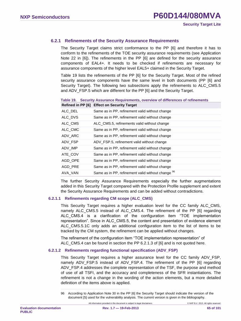
NXP Semiconductors P60D144/080MVA Security Target Lite
All information provided in this document is subject to legal disclaimers. © NXP B.V. 2013. All rights reserved.
Evaluation documentation PUBLIC
Rev. 1.7 — 19-Feb-2013 65 of 101
6.2.1 Refinements of the Security Assurance Requirements
The Security Target claims strict conformance to the PP [6] and therefore it has to
conform to the refinements of the TOE security assurance requirements (see Application
Note 22 in [6]). The refinements in the PP [6] are defined for the security assurance
components of EAL4+. It needs to be checked if refinements are necessary for
assurance components of the higher level EAL5+ claimed in the Security Target.
Table 19 lists the refinements of the PP [6] for the Security Target. Most of the refined
security assurance components have the same level in both documents (PP [6] and
Security Target). The following two subsections apply the refinements to ALC_CMS.5
and ADV_FSP.5 which are different for the PP [6] and the Security Target.
Table 19. Security Assurance Requirements, overview of differences of refinements
Refined in PP [6] Effect on Security Target
ALC_DEL Same as in PP, refinement valid without change
ALC_DVS Same as in PP, refinement valid without change
ALC_CMS ALC_CMS.5, refinements valid without change
ALC_CMC Same as in PP, refinement valid without change
ADV_ARC Same as in PP, refinement valid without change
ADV_FSP ADV_FSP.5, refinement valid without change
ADV_IMP Same as in PP, refinement valid without change
ATE_COV Same as in PP, refinement valid without change
AGD_OPE Same as in PP, refinement valid without change
AGD_PRE Same as in PP, refinement valid without change
AVA_VAN Same as in PP, refinement valid without change 96
The further Security Assurance Requirements especially the further augmentations
added in this Security Target compared with the Protection Profile supplement and extent
the Security Assurance Requirements and can be added without contradictions.
6.2.1.1 Refinements regarding CM scope (ALC_CMS)
This Security Target requires a higher evaluation level for the CC family ALC_CMS,
namely ALC_CMS.5 instead of ALC_CMS.4. The refinement of the PP [6] regarding
ALC_CMS.4 is a clarification of the configuration item “TOE implementation
representation”. Since in ALC_CMS.5, the content and presentation of evidence element
ALC_CMS.5.1C only adds an additional configuration item to the list of items to be
tracked by the CM system, the refinement can be applied without changes.
The refinement of the configuration item “TOE implementation representation” of
ALC_CMS.4 can be found in section the PP 6.2.1.3 of [6] and is not quoted here.
6.2.1.2 Refinements regarding functional specification (ADV_FSP)
This Security Target requires a higher assurance level for the CC family ADV_FSP,
namely ADV_FSP.5 instead of ADV_FSP.4. The refinement of the PP [6] regarding
ADV_FSP.4 addresses the complete representation of the TSF, the purpose and method
of use of all TSFI, and the accuracy and completeness of the SFR instantiations. The
refinement is not a change in the wording of the action elements, but a more detailed
definition of the items above is applied.
96 According to Application Note 30 in the PP [6] the Security Target should indicate the version of the
document [5] used for the vulnerability analysis. The current version is given in the bibliography.
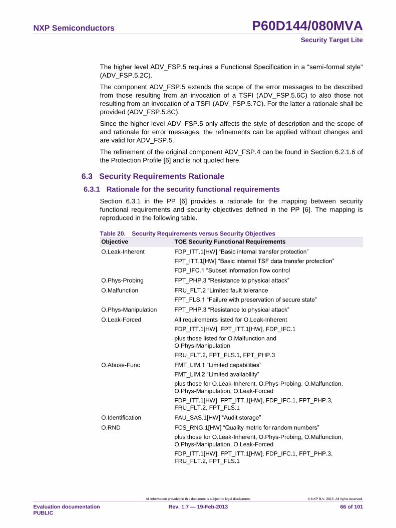
NXP Semiconductors P60D144/080MVA Security Target Lite
All information provided in this document is subject to legal disclaimers. © NXP B.V. 2013. All rights reserved.
Evaluation documentation PUBLIC
Rev. 1.7 — 19-Feb-2013 66 of 101
The higher level ADV_FSP.5 requires a Functional Specification in a “semi-formal style"
(ADV_FSP.5.2C).
The component ADV_FSP.5 extends the scope of the error messages to be described
from those resulting from an invocation of a TSFI (ADV_FSP.5.6C) to also those not
resulting from an invocation of a TSFI (ADV_FSP.5.7C). For the latter a rationale shall be
provided (ADV_FSP.5.8C).
Since the higher level ADV_FSP.5 only affects the style of description and the scope of
and rationale for error messages, the refinements can be applied without changes and
are valid for ADV_FSP.5.
The refinement of the original component ADV_FSP.4 can be found in Section 6.2.1.6 of
the Protection Profile [6] and is not quoted here.
6.3 Security Requirements Rationale
6.3.1 Rationale for the security functional requirements
Section 6.3.1 in the PP [6] provides a rationale for the mapping between security
functional requirements and security objectives defined in the PP [6]. The mapping is
reproduced in the following table.
Table 20. Security Requirements versus Security Objectives
Objective TOE Security Functional Requirements
O.Leak-Inherent FDP_ITT.1[HW] “Basic internal transfer protection”
FPT_ITT.1[HW] “Basic internal TSF data transfer protection”
FDP_IFC.1 “Subset information flow control
O.Phys-Probing FPT_PHP.3 “Resistance to physical attack”
O.Malfunction FRU_FLT.2 “Limited fault tolerance
FPT_FLS.1 “Failure with preservation of secure state”
O.Phys-Manipulation FPT_PHP.3 “Resistance to physical attack”
O.Leak-Forced All requirements listed for O.Leak-Inherent
FDP_ITT.1[HW], FPT_ITT.1[HW], FDP_IFC.1
plus those listed for O.Malfunction and
O.Phys-Manipulation
FRU_FLT.2, FPT_FLS.1, FPT_PHP.3
O.Abuse-Func FMT_LIM.1 “Limited capabilities”
FMT_LIM.2 “Limited availability”
plus those for O.Leak-Inherent, O.Phys-Probing, O.Malfunction,
O.Phys-Manipulation, O.Leak-Forced
FDP_ITT.1[HW], FPT_ITT.1[HW], FDP_IFC.1, FPT_PHP.3,
FRU_FLT.2, FPT_FLS.1
O.Identification FAU_SAS.1[HW] “Audit storage”
O.RND FCS_RNG.1[HW] “Quality metric for random numbers”
plus those for O.Leak-Inherent, O.Phys-Probing, O.Malfunction,
O.Phys-Manipulation, O.Leak-Forced
FDP_ITT.1[HW], FPT_ITT.1[HW], FDP_IFC.1, FPT_PHP.3,
FRU_FLT.2, FPT_FLS.1
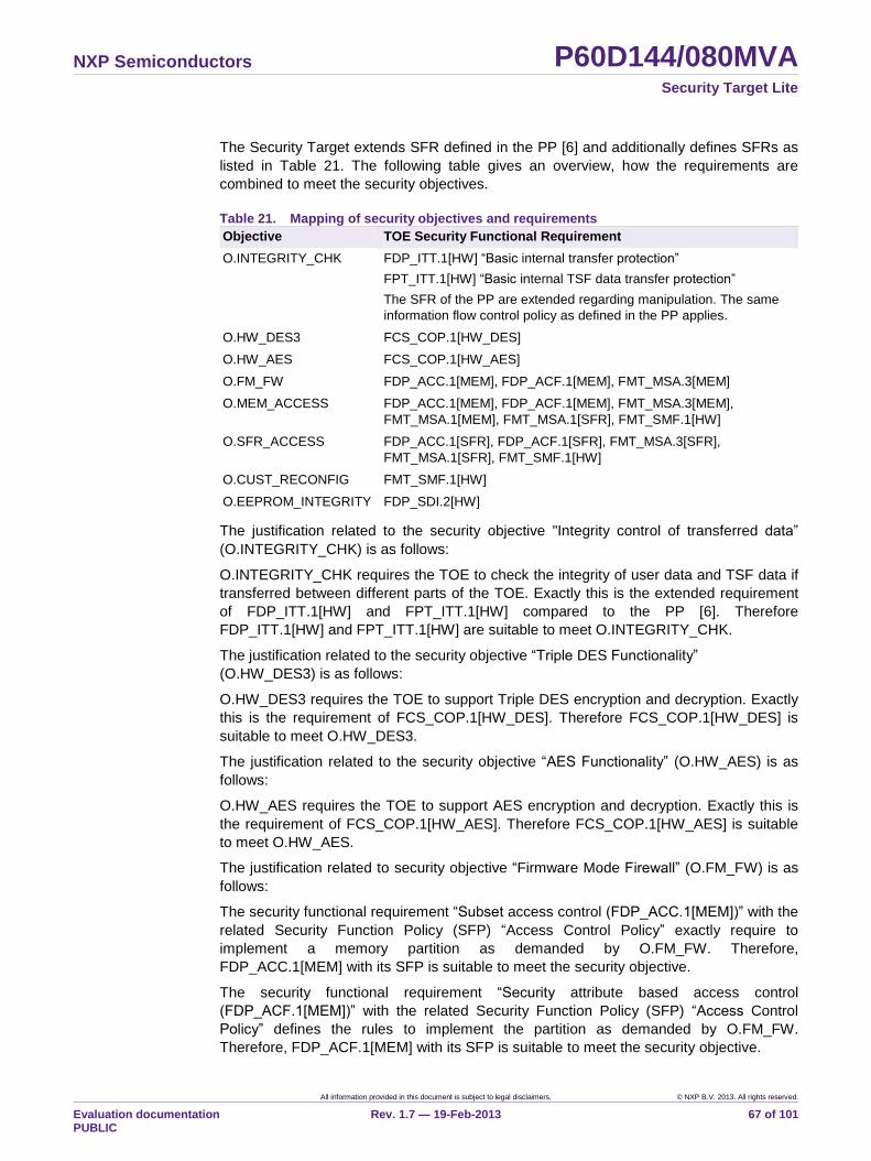
NXP Semiconductors P60D144/080MVA Security Target Lite
All information provided in this document is subject to legal disclaimers. © NXP B.V. 2013. All rights reserved.
Evaluation documentation PUBLIC
Rev. 1.7 — 19-Feb-2013 67 of 101
The Security Target extends SFR defined in the PP [6] and additionally defines SFRs as
listed in Table 21. The following table gives an overview, how the requirements are
combined to meet the security objectives.
Table 21. Mapping of security objectives and requirements
Objective TOE Security Functional Requirement
O.INTEGRITY_CHK FDP_ITT.1[HW] “Basic internal transfer protection”
FPT_ITT.1[HW] “Basic internal TSF data transfer protection”
The SFR of the PP are extended regarding manipulation. The same
information flow control policy as defined in the PP applies.
O.HW_DES3 FCS_COP.1[HW_DES]
O.HW_AES FCS_COP.1[HW_AES]
O.FM_FW FDP_ACC.1[MEM], FDP_ACF.1[MEM], FMT_MSA.3[MEM]
O.MEM_ACCESS FDP_ACC.1[MEM], FDP_ACF.1[MEM], FMT_MSA.3[MEM],
FMT_MSA.1[MEM], FMT_MSA.1[SFR], FMT_SMF.1[HW]
O.SFR_ACCESS FDP_ACC.1[SFR], FDP_ACF.1[SFR], FMT_MSA.3[SFR],
FMT_MSA.1[SFR], FMT_SMF.1[HW]
O.CUST_RECONFIG FMT_SMF.1[HW]
O.EEPROM_INTEGRITY FDP_SDI.2[HW]
The justification related to the security objective "Integrity control of transferred data”
(O.INTEGRITY_CHK) is as follows:
O.INTEGRITY_CHK requires the TOE to check the integrity of user data and TSF data if
transferred between different parts of the TOE. Exactly this is the extended requirement
of FDP_ITT.1[HW] and FPT_ITT.1[HW] compared to the PP [6]. Therefore
FDP_ITT.1[HW] and FPT_ITT.1[HW] are suitable to meet O.INTEGRITY_CHK.
The justification related to the security objective “Triple DES Functionality”
(O.HW_DES3) is as follows:
O.HW_DES3 requires the TOE to support Triple DES encryption and decryption. Exactly
this is the requirement of FCS_COP.1[HW_DES]. Therefore FCS_COP.1[HW_DES] is
suitable to meet O.HW_DES3.
The justification related to the security objective “AES Functionality” (O.HW_AES) is as
follows:
O.HW_AES requires the TOE to support AES encryption and decryption. Exactly this is
the requirement of FCS_COP.1[HW_AES]. Therefore FCS_COP.1[HW_AES] is suitable
to meet O.HW_AES.
The justification related to security objective “Firmware Mode Firewall” (O.FM_FW) is as
follows:
The security functional requirement “Subset access control (FDP_ACC.1[MEM])” with the
related Security Function Policy (SFP) “Access Control Policy” exactly require to
implement a memory partition as demanded by O.FM_FW. Therefore,
FDP_ACC.1[MEM] with its SFP is suitable to meet the security objective.
The security functional requirement “Security attribute based access control
(FDP_ACF.1[MEM])” with the related Security Function Policy (SFP) “Access Control
Policy” defines the rules to implement the partition as demanded by O.FM_FW.
Therefore, FDP_ACF.1[MEM] with its SFP is suitable to meet the security objective.
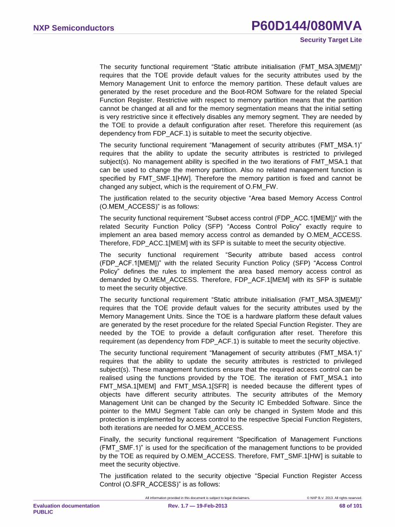
NXP Semiconductors P60D144/080MVA Security Target Lite
All information provided in this document is subject to legal disclaimers. © NXP B.V. 2013. All rights reserved.
Evaluation documentation PUBLIC
Rev. 1.7 — 19-Feb-2013 68 of 101
The security functional requirement “Static attribute initialisation (FMT_MSA.3[MEM])”
requires that the TOE provide default values for the security attributes used by the
Memory Management Unit to enforce the memory partition. These default values are
generated by the reset procedure and the Boot-ROM Software for the related Special
Function Register. Restrictive with respect to memory partition means that the partition
cannot be changed at all and for the memory segmentation means that the initial setting
is very restrictive since it effectively disables any memory segment. They are needed by
the TOE to provide a default configuration after reset. Therefore this requirement (as
dependency from FDP_ACF.1) is suitable to meet the security objective.
The security functional requirement “Management of security attributes (FMT_MSA.1)”
requires that the ability to update the security attributes is restricted to privileged
subject(s). No management ability is specified in the two iterations of FMT_MSA.1 that
can be used to change the memory partition. Also no related management function is
specified by FMT_SMF.1[HW]. Therefore the memory partition is fixed and cannot be
changed any subject, which is the requirement of O.FM_FW.
The justification related to the security objective “Area based Memory Access Control
(O.MEM_ACCESS)” is as follows:
The security functional requirement “Subset access control (FDP_ACC.1[MEM])” with the
related Security Function Policy (SFP) “Access Control Policy” exactly require to
implement an area based memory access control as demanded by O.MEM_ACCESS.
Therefore, FDP_ACC.1[MEM] with its SFP is suitable to meet the security objective.
The security functional requirement “Security attribute based access control
(FDP_ACF.1[MEM])” with the related Security Function Policy (SFP) “Access Control
Policy” defines the rules to implement the area based memory access control as
demanded by O.MEM_ACCESS. Therefore, FDP_ACF.1[MEM] with its SFP is suitable
to meet the security objective.
The security functional requirement “Static attribute initialisation (FMT_MSA.3[MEM])”
requires that the TOE provide default values for the security attributes used by the
Memory Management Units. Since the TOE is a hardware platform these default values
are generated by the reset procedure for the related Special Function Register. They are
needed by the TOE to provide a default configuration after reset. Therefore this
requirement (as dependency from FDP_ACF.1) is suitable to meet the security objective.
The security functional requirement “Management of security attributes (FMT_MSA.1)”
requires that the ability to update the security attributes is restricted to privileged
subject(s). These management functions ensure that the required access control can be
realised using the functions provided by the TOE. The iteration of FMT_MSA.1 into
FMT_MSA.1[MEM] and FMT_MSA.1[SFR] is needed because the different types of
objects have different security attributes. The security attributes of the Memory
Management Unit can be changed by the Security IC Embedded Software. Since the
pointer to the MMU Segment Table can only be changed in System Mode and this
protection is implemented by access control to the respective Special Function Registers,
both iterations are needed for O.MEM_ACCESS.
Finally, the security functional requirement “Specification of Management Functions
(FMT_SMF.1)” is used for the specification of the management functions to be provided
by the TOE as required by O.MEM_ACCESS. Therefore, FMT_SMF.1[HW] is suitable to
meet the security objective.
The justification related to the security objective “Special Function Register Access
Control (O.SFR_ACCESS)” is as follows:
NXP Semiconductors P60D144/080MVA Security Target Lite
All information provided in this document is subject to legal disclaimers. © NXP B.V. 2013. All rights reserved.
Evaluation documentation PUBLIC
Rev. 1.7 — 19-Feb-2013 69 of 101
The security functional requirement “Subset access control (FDP_ACC.1[SFR])” with the
related Security Function Policy (SFP) “Access Control Policy” require to implement
access control for Special Function Register as demanded by O.SFR_ACCESS.
Therefore, FDP_ACC.1[SFR] with its SFP is suitable to meet the security objective.
The access to Special Function Register is related to the CPU mode. The Special
Function Register used to configure the Memory Management Unit can only be accessed
in System Mode. The Special Function Register required to use hardware components
like e.g. the coprocessors or the Random Number Generator can be accessed in System
Mode as specified by the Security Function Policy (SFP) “Access Control Policy”. In User
Mode only Special Function Register required to run the CPU are accessible by default.
In addition, specific Special Function Registers related to hardware components can be
made accessible for the User Mode if the Memory Management Unit is configured to
allow this.
The security functional requirement “Security attribute based access control
(FDP_ACF.1[SFR])” with the related Security Function Policy “Access Control Policy”
exactly require certain security attributes to implement the access control to Special
Function Register as required by O.SFR_ACCESS. Therefore, FDP_ACF.1[SFR] with its
SFP is suitable to meet the security objective.
The security functional requirement “Static attribute initialisation (FMT_MSA.3[SFR])”
requires that the TOE provides default values for the Special Function Register (values
as well as access control). The default values are needed to ensure a defined setup for
the operation of the TOE. Therefore this requirement (as dependency from FDP_ACF.1)
is suitable to meet the security objective.
The security functional requirement “Management of security attributes
(FMT_MSA.1[SFR])” is realised in a way that – besides the definition of access rights to
Special Function Registers related to hardware components in User Mode and Firmware
Mode – no management of the security attributes is possible because the attributes are
implemented in the hardware and cannot be changed.
Finally, the security functional requirement “Specification of Management Functions
(FMT_SMF.1)” is used for the specification of the management functions to be provided
by the TOE as demanded by O.SFR_ACCESS. Therefore, FMT_SMF.1[HW] is suitable
to meet the security objective.
Note that the iteration of FDP_ACF.1 and FDP_ACC.1 with the respective dependencies
are needed to separate the different types of objects because they have different security
attributes.
The justification related to the security objective “Integrity support of data stored in
EEPROM” (O.EEPROM_INTEGRITY) is as follows:
The security functional requirement “Stored data integrity monitoring and action
(FDP_SDI.2)” is used for the specification of the control function to adjust the conditions
of an EEPROM block such that the integrity of the data read from EEPROM is ensured
even if the characteristics of the EEPROM changed e.g. due to ageing. Therefore,
FDP_SDI.2[HW] is suitable to meet the security objective.
The justification related to the security objective “Post Delivery Configuration”
(O.CUST_RECONFIG) is as follows:
The security functional requirement “Specification of Management Functions
(FMT_SMF.1)” is used for the specification of the management functions to be provided
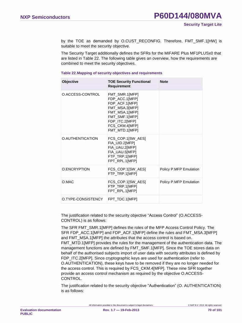
NXP Semiconductors P60D144/080MVA Security Target Lite
All information provided in this document is subject to legal disclaimers. © NXP B.V. 2013. All rights reserved.
Evaluation documentation PUBLIC
Rev. 1.7 — 19-Feb-2013 70 of 101
by the TOE as demanded by O.CUST_RECONFIG. Therefore, FMT_SMF.1[HW] is
suitable to meet the security objective.
The Security Target additionally defines the SFRs for the MIFARE Plus MF1PLUSx0 that
are listed in Table 22. The following table gives an overview, how the requirements are
combined to meet the security objectives.
Table 22. Mapping of security objectives and requirements
Objective TOE Security Functional
Requirement
Note
O.ACCESS-CONTROL FMT_SMR.1[MFP]
FDP_ACC.1[MFP]
FDP_ACF.1[MFP]
FMT_MSA.3[MFP]
FMT_MSA.1[MFP]
FMT_SMF.1[MFP]
FDP_ITC.2[MFP]
FCS_CKM.4[MFP]
FMT_MTD.1[MFP]
O.AUTHENTICATION FCS_COP.1[SW_AES]
FIA_UID.2[MFP]
FIA_UAU.2[MFP]
FIA_UAU.5[MFP]
FTP_TRP.1[MFP]
FPT_RPL.1[MFP]
O.ENCRYPTION FCS_COP.1[SW_AES]
FTP_TRP.1[MFP]
Policy P.MFP Emulation
O.MAC FCS_COP.1[SW_AES]
FTP_TRP.1[MFP]
FPT_RPL.1[MFP]
Policy P.MFP Emulation
O.TYPE-CONSISTENCY FPT_TDC.1[MFP]
The justification related to the security objective “Access Control” (O.ACCESS-
CONTROL) is as follows:
The SFR FMT_SMR.1[MFP] defines the roles of the MFP Access Control Policy. The
SFR FDP_ACC.1[MFP] and FDP_ACF.1[MFP] define the rules and FMT_MSA.3[MFP]
and FMT_MSA.1[MFP] the attributes that the access control is based on.
FMT_MTD.1[MFP] provides the rules for the management of the authentication data. The
management functions are defined by FMT_SMF.1[MFP]. Since the TOE stores data on
behalf of the authorised subjects import of user data with security attributes is defined by
FDP_ITC.2[MFP]. Since cryptographic keys are used for authentication (refer to
O.AUTHENTICATION), these keys have to be removed if they are no longer needed for
the access control. This is required by FCS_CKM.4[MFP]. These nine SFR together
provide an access control mechanism as required by the objective O.ACCESS-
CONTROL.
The justification related to the security objective “Authentication” (O. AUTHENTICATION)
is as follows:
NXP Semiconductors P60D144/080MVA Security Target Lite
All information provided in this document is subject to legal disclaimers. © NXP B.V. 2013. All rights reserved.
Evaluation documentation PUBLIC
Rev. 1.7 — 19-Feb-2013 71 of 101
The SFR FCS_COP.1[SW_AES] requires that the TOE provides the basic cryptographic
algorithm that can be used to perform the authentication. The SFR FIA_UID.2[MFP],
FIA_UAU.2[MFP] and FIA_UAU.5[MFP] together define that users must be identified and
authenticated before any action. FTP_TRP.1[MFP] requires a trusted communication
path between the TOE and remote users, FTP_TRP.1[MFP].3 especially requires
“authentication requests”. Together with FPT_RPL.1[MFP] which requires a replay
detection for these authentication requests the six SFR fulfil the objective O.
AUTHENTICATION.
The justification related to the security objective “Confidential Communication”
(O.ENCRYPTION) is as follows:
The SFR FCS_COP.1[SW_AES] requires that the TOE provides the basic cryptographic
algorithms that can be used to protect the communication by encryption.
FTP_TRP.1[MFP] requires a trusted communication path between the TOE and remote
users, FTP_TRP.1[MFP].3 especially requires a trusted path for “authentication requests,
confidentiality and/or data integrity verification for data transfers based on a setting in the
MFP Configuration Block”. These two SFR fulfil the objective O. ENCRYPTION.
The justification related to the security objective “Integrity-protected Communication”
(O.MAC) is as follows:
The SFR FCS_COP.1[SW_AES] requires that the TOE provides the basic cryptographic
algorithms that can be used to compute a MAC which can protect the integrity of the
communication. FTP_TRP.1[MFP] requires a trusted communication path between the
TOE and remote users, FTP_TRP.1[MFP].3 especially requires “confidentiality and/or
data integrity verification for data transfers on request of the file owner”. Together with
FPT_RPL.1[MFP] which requires a replay detection for these data transfers the three
SFR fulfil the objective O.MAC.
The justification related to the security objective “Data type consistency” (O.TYPE-
CONSISTENCY) is as follows:
The SFR FPT_TDC.1[MFP] requires the TOE to consistently interpret data blocks. The
TOE will honour the respective file formats and boundaries (i.e. upper and lower limits,
size limitations). This meets the objective O.TYPE-CONSISTENCY.
6.3.2 Dependencies of security functional requirements
The dependencies listed in the PP [6] are independent of the additional dependencies
listed in the table below. The dependencies of the PP [6] are fulfilled within the PP [6]
and at least one dependency is considered to be satisfied.
The following discussion demonstrates how the dependencies defined by Part 2 of the
Common Criteria [2] for the requirements specified in Sections 6.1.2 and 6.1.4 are
satisfied.
The dependencies defined in the Common Criteria are listed in the table below:
Table 23. Dependencies of security functional requirements
Security Functional
Requirement
Dependencies Fulfilled by security
requirements in this ST
FCS_COP.1[HW_DES] FDP_ITC.1 or FDP_ITC.2, or
FCS_CKM.1
FCS_CKM.4
See discussion below
FCS_COP.1[HW_AES] FDP_ITC.1 or FDP_ITC.2, or
FCS_CKM.1
See discussion below
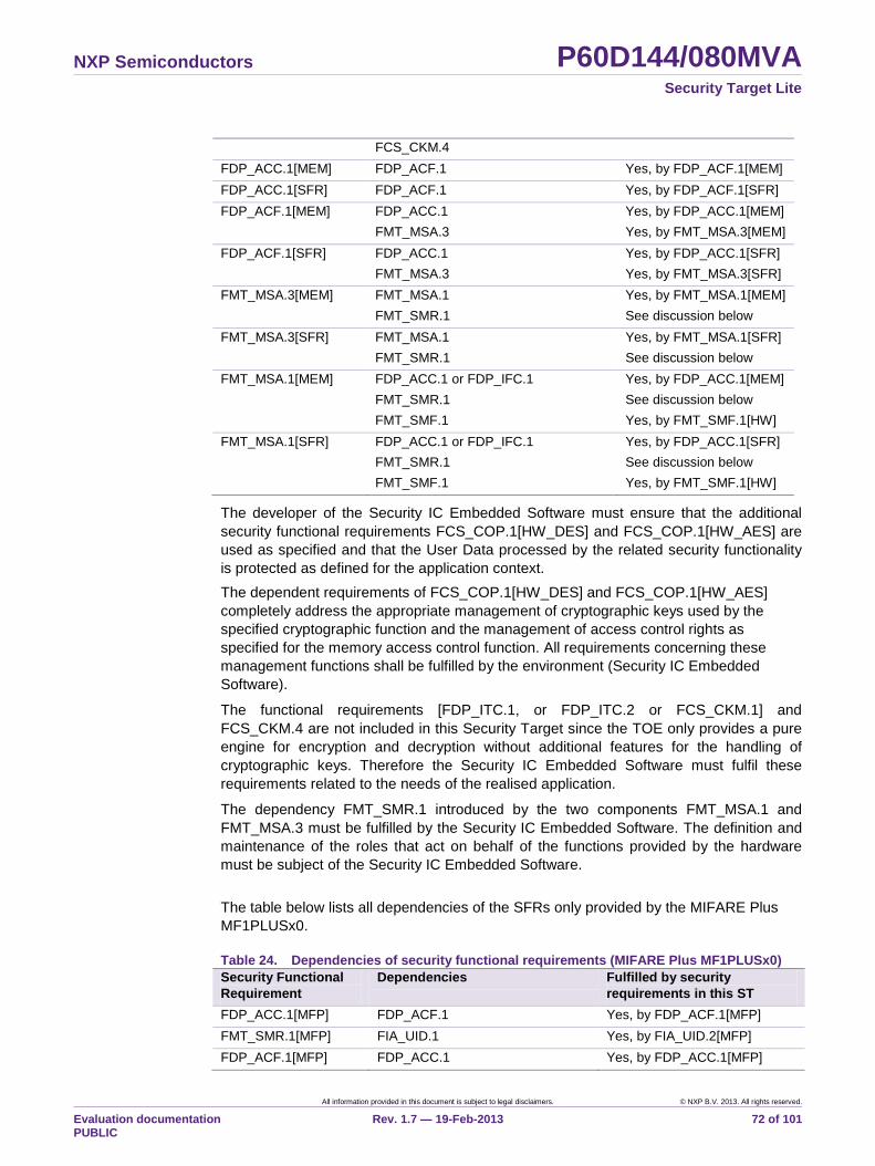
NXP Semiconductors P60D144/080MVA Security Target Lite
All information provided in this document is subject to legal disclaimers. © NXP B.V. 2013. All rights reserved.
Evaluation documentation PUBLIC
Rev. 1.7 — 19-Feb-2013 72 of 101
FCS_CKM.4
FDP_ACC.1[MEM] FDP_ACF.1 Yes, by FDP_ACF.1[MEM]
FDP_ACC.1[SFR] FDP_ACF.1 Yes, by FDP_ACF.1[SFR]
FDP_ACF.1[MEM] FDP_ACC.1
FMT_MSA.3
Yes, by FDP_ACC.1[MEM]
Yes, by FMT_MSA.3[MEM]
FDP_ACF.1[SFR] FDP_ACC.1
FMT_MSA.3
Yes, by FDP_ACC.1[SFR]
Yes, by FMT_MSA.3[SFR]
FMT_MSA.3[MEM] FMT_MSA.1
FMT_SMR.1
Yes, by FMT_MSA.1[MEM]
See discussion below
FMT_MSA.3[SFR] FMT_MSA.1
FMT_SMR.1
Yes, by FMT_MSA.1[SFR]
See discussion below
FMT_MSA.1[MEM] FDP_ACC.1 or FDP_IFC.1
FMT_SMR.1
FMT_SMF.1
Yes, by FDP_ACC.1[MEM]
See discussion below
Yes, by FMT_SMF.1[HW]
FMT_MSA.1[SFR] FDP_ACC.1 or FDP_IFC.1
FMT_SMR.1
FMT_SMF.1
Yes, by FDP_ACC.1[SFR]
See discussion below
Yes, by FMT_SMF.1[HW]
The developer of the Security IC Embedded Software must ensure that the additional
security functional requirements FCS_COP.1[HW_DES] and FCS_COP.1[HW_AES] are
used as specified and that the User Data processed by the related security functionality
is protected as defined for the application context.
The dependent requirements of FCS_COP.1[HW_DES] and FCS_COP.1[HW_AES]
completely address the appropriate management of cryptographic keys used by the
specified cryptographic function and the management of access control rights as
specified for the memory access control function. All requirements concerning these
management functions shall be fulfilled by the environment (Security IC Embedded
Software).
The functional requirements [FDP_ITC.1, or FDP_ITC.2 or FCS_CKM.1] and
FCS_CKM.4 are not included in this Security Target since the TOE only provides a pure
engine for encryption and decryption without additional features for the handling of
cryptographic keys. Therefore the Security IC Embedded Software must fulfil these
requirements related to the needs of the realised application.
The dependency FMT_SMR.1 introduced by the two components FMT_MSA.1 and
FMT_MSA.3 must be fulfilled by the Security IC Embedded Software. The definition and
maintenance of the roles that act on behalf of the functions provided by the hardware
must be subject of the Security IC Embedded Software.
The table below lists all dependencies of the SFRs only provided by the MIFARE Plus
MF1PLUSx0.
Table 24. Dependencies of security functional requirements (MIFARE Plus MF1PLUSx0)
Security Functional
Requirement
Dependencies Fulfilled by security
requirements in this ST
FDP_ACC.1[MFP] FDP_ACF.1 Yes, by FDP_ACF.1[MFP]
FMT_SMR.1[MFP] FIA_UID.1 Yes, by FIA_UID.2[MFP]
FDP_ACF.1[MFP] FDP_ACC.1 Yes, by FDP_ACC.1[MFP]
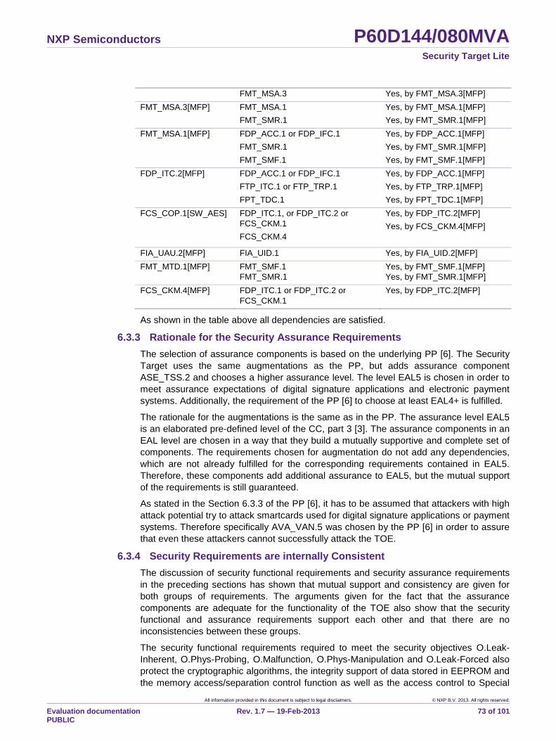
NXP Semiconductors P60D144/080MVA Security Target Lite
All information provided in this document is subject to legal disclaimers. © NXP B.V. 2013. All rights reserved.
Evaluation documentation PUBLIC
Rev. 1.7 — 19-Feb-2013 73 of 101
FMT_MSA.3 Yes, by FMT_MSA.3[MFP]
FMT_MSA.3[MFP] FMT_MSA.1
FMT_SMR.1
Yes, by FMT_MSA.1[MFP]
Yes, by FMT_SMR.1[MFP]
FMT_MSA.1[MFP] FDP_ACC.1 or FDP_IFC.1
FMT_SMR.1
FMT_SMF.1
Yes, by FDP_ACC.1[MFP]
Yes, by FMT_SMR.1[MFP]
Yes, by FMT_SMF.1[MFP]
FDP_ITC.2[MFP] FDP_ACC.1 or FDP_IFC.1
FTP_ITC.1 or FTP_TRP.1
FPT_TDC.1
Yes, by FDP_ACC.1[MFP]
Yes, by FTP_TRP.1[MFP]
Yes, by FPT_TDC.1[MFP]
FCS_COP.1[SW_AES] FDP_ITC.1, or FDP_ITC.2 or
FCS_CKM.1
FCS_CKM.4
Yes, by FDP_ITC.2[MFP]
Yes, by FCS_CKM.4[MFP]
FIA_UAU.2[MFP] FIA_UID.1 Yes, by FIA_UID.2[MFP]
FMT_MTD.1[MFP] FMT_SMF.1
FMT_SMR.1
Yes, by FMT_SMF.1[MFP]
Yes, by FMT_SMR.1[MFP]
FCS_CKM.4[MFP] FDP_ITC.1 or FDP_ITC.2 or
FCS_CKM.1
Yes, by FDP_ITC.2[MFP]
As shown in the table above all dependencies are satisfied.
6.3.3 Rationale for the Security Assurance Requirements
The selection of assurance components is based on the underlying PP [6]. The Security
Target uses the same augmentations as the PP, but adds assurance component
ASE_TSS.2 and chooses a higher assurance level. The level EAL5 is chosen in order to
meet assurance expectations of digital signature applications and electronic payment
systems. Additionally, the requirement of the PP [6] to choose at least EAL4+ is fulfilled.
The rationale for the augmentations is the same as in the PP. The assurance level EAL5
is an elaborated pre-defined level of the CC, part 3 [3]. The assurance components in an
EAL level are chosen in a way that they build a mutually supportive and complete set of
components. The requirements chosen for augmentation do not add any dependencies,
which are not already fulfilled for the corresponding requirements contained in EAL5.
Therefore, these components add additional assurance to EAL5, but the mutual support
of the requirements is still guaranteed.
As stated in the Section 6.3.3 of the PP [6], it has to be assumed that attackers with high
attack potential try to attack smartcards used for digital signature applications or payment
systems. Therefore specifically AVA_VAN.5 was chosen by the PP [6] in order to assure
that even these attackers cannot successfully attack the TOE.
6.3.4 Security Requirements are internally Consistent
The discussion of security functional requirements and security assurance requirements
in the preceding sections has shown that mutual support and consistency are given for
both groups of requirements. The arguments given for the fact that the assurance
components are adequate for the functionality of the TOE also show that the security
functional and assurance requirements support each other and that there are no
inconsistencies between these groups.
The security functional requirements required to meet the security objectives O.Leak-
Inherent, O.Phys-Probing, O.Malfunction, O.Phys-Manipulation and O.Leak-Forced also
protect the cryptographic algorithms, the integrity support of data stored in EEPROM and
the memory access/separation control function as well as the access control to Special
NXP Semiconductors P60D144/080MVA Security Target Lite
All information provided in this document is subject to legal disclaimers. © NXP B.V. 2013. All rights reserved.
Evaluation documentation PUBLIC
Rev. 1.7 — 19-Feb-2013 74 of 101
Function Register implemented according to the security functional requirement
FCS_COP.1[HW_DES], FCS_COP.1[HW_AES], FDP_SDI.2[HW] and
FDP_ACC.1[MEM], FDP_ACC.1[SFR] with reference to the Access Control Policies
defined in FDP_ACF.1[MEM] and FDP_ACF.1[SFR]. Therefore, these security functional
requirements support the secure implementation and operation of
FCS_COP.1[HW_DES], FCS_COP.1[HW_AES] and of FDP_ACC.1 with FDP_ACF.1 as
well as the dependent security functional requirements.
The extension of the security functional requirements FDP_ITT.1[HW] and FTP_ITT.1
compared to the underlying PP [6] adds the detection of faults during the transfer of user
data or TSF data between internal components of the TOE. The protection against
leakage is not weakened by this extension.
The Security Functionality defined by P.MFP-Emulation is only provided if the MIFARE
Plus MF1PLUSx0 is called by the Security IC Embedded Software. However the Security
Functionality provided by P.MFP-Emulation cannot be influenced by the Security IC
Embedded Software because of the partitioning of the hardware platform by the
Firmware Firewall. The partitioning works in both directions so that the Security
Functionality of the Security IC Embedded Software cannot be influenced by the MIFARE
Plus MF1PLUSx0.
A hardware platform including the IC Dedicated Software requires Security IC Embedded
Software to build a secure product. Thereby the Security IC Embedded Software must
support the security functionality of the hardware as well as the IC Dedicated Support
Software and implement a sufficient management of the security services implemented
by the hardware platform including the IC Dedicated Software. The realisation of the
Security Functional Requirements within the TOE provides a good balance between
flexible configuration and restrictions to ensure a secure behaviour of the TOE.
NXP Semiconductors P60D144/080MVA Security Target Lite
All information provided in this document is subject to legal disclaimers. © NXP B.V. 2013. All rights reserved.
Evaluation documentation PUBLIC
Rev. 1.7 — 19-Feb-2013 75 of 101
7. TOE Summary Specification
This chapter is composed of sections “Portions of the TOE Security Functionality” and
“TOE Summary Specification Rationale”.
7.1 Portions of the TOE Security Functionality
The TOE Security Functionality (TSF) directly corresponds to the TOE security functional
requirements defined in Chapter 6. The Security Functionality provided by the TOE is
split into Security Services (SS) and Security Features (SF). Both are active and
applicable to phases 4 to 7 of the Security IC product life-cycle.
Note: Parts of the security functionality are configured at the end of phase 3 and
all security functionality is active after phase 3 or phase 4 depending on the
delivery form.
The TOE also comprises security mechanisms, which are not listed as security
functionality in the following. Such mechanisms do not implement a complete Security
Services or Security Features. They can be used to implement further Security Services
and/or Security Features based on Security IC Embedded Software using these security
mechanisms, e.g. the Fame2 coprocessor for asymmetric cryptographic algorithms.
7.1.1 Security Services
SS.RNG: Random Number Generator
The Random Number Generator continuously produces random numbers with a length of
one byte. The TOE implements SS.RNG by means of a physical hardware Random
Number Generator working stable within the valid ranges of operating conditions, which
are guaranteed by SF.OPC.
The TSF provides a hardware test functionality, which can be used by the Security IC
Embedded Software to hardware detects or bad quality of the produced random
numbers.
According to AIS31 [7] the Random Number Generator claims the functionality class
PTG2. This means that the Random Number Generator is suitable for generation of
signature key pairs, generation of session keys for symmetric encryption mechanisms,
random padding bits, zero-knowledge proofs, the generation of seeds for DRNGs and
fulfils the online test requirements defined in [7].
SS.HW_DES: Triple-DES coprocessor
The TOE provides the Triple Data Encryption Algorithm (TDEA) according to the Data
Encryption Standard (DES) [20]. SS.HW_DES is a modular basic cryptographic function,
which provides the TDEA algorithm as defined by FIPS PUB 46 by means of a hardware
coprocessor and supports (a) the 3-key Triple-DEA algorithm according to keying option
1 and (b) the 2-key Triple DEA algorithm according to keying option 2 in FIPS PUB 46-3
[20]. The two/three 56-bit keys (112-/168-bit) for the 2-key/3-key Triple DES algorithm
shall be provided by the Security IC Embedded Software.
SS.HW_DES also supports hardware XOR-operation of two data blocks to support
chaining modes of the TDES if this is configured by the Security IC Embedded Software.
SS.HW_AES: AES coprocessor
The TOE provides the Advanced Encryption Standard (AES) algorithm according to the
Advanced Encryption Standard as defined by FIPS PUB 197 [21]. SS.HW_AES is a
NXP Semiconductors P60D144/080MVA Security Target Lite
All information provided in this document is subject to legal disclaimers. © NXP B.V. 2013. All rights reserved.
Evaluation documentation PUBLIC
Rev. 1.7 — 19-Feb-2013 76 of 101
modular basic cryptographic function, which provides the AES algorithm by means of a
hardware coprocessor and supports the AES algorithm with three different key lengths of
128, 192 or 256 bit. The keys for the AES algorithm shall be provided by the Security IC
Embedded Software. SS.HW_AES also supports hardware XOR-operation of two data
blocks to support chaining modes of the AES if this is configured by the Security IC
Embedded Software.
SS.CRC: Cyclic Redundancy Check
The TOE provides a 16- and 32-bit Cyclic Redundancy Calculation (CRC) checksum
calculation mechanism. SS.CRC is a modular checksum calculation function, which
provides checksum calculation supporting the CRC polynomials 0x1021 (CCITT,X25) for
16-bit checksum calculation and 0x04C11DB7 for 32-bit checksum calculation, which
must be selected by the Security IC Embedded Software. In combination with the
memory verify functionality of the CPU SS.CRC provides a mechanism for checksum
calculation over memory segments applying memory access control mechanisms
according to SF.MEM_ACC without reading these memory segments by the Security IC
Embedded Software. If SS.CRC is used in combination with the copy machine the CRC
is calculated during the transfer of the data between different parts of the TOE. SS.CRC
is used in Boot Mode by the IC Dedicated Software for calculation of a CRC checksum
during the transfer of the Security Rows content into Special Function Registers.
SS.RECONFIG: Post Delivery Configuration
SS.RECONFIG realizes the Post Delivery Configuration. The Hardware Post Delivery
Configuration can be used by the customer to set the accessible size of the EEPROM
and CXRAM and to enable or disable the Fame2 coprocessor, the AES coprocessor and
the contactless interface. The configuration values of the Hardware Post Delivery
Configuration options are stored in a special area in the Security Row (see SF.COMP).
Note that if the Fame2 coprocessor and the AES coprocessor are disabled, both will no
longer be available to the Security IC Embedded Software and attempting to use it will
raise an exception. This means the availability of SS.HW_AES is configurable.
The customer can change the values of Hardware Post Delivery Configuration through
invoking the Hardware Post Delivery Configuration functionality in the Boot-ROM
Software (see SF.MEM_ACC). This functionality is invoked by using the chip health
mode via the ISO/IEC 7816 interface and applying the required Post Delivery
Configuration commands.
The customer can change these values as many times as he wishes. However, once he
calls this Boot-ROM Software using the chip health mode via the ISO/IEC 7816 interface
with a certain parameter set to a specific value, the options are locked permanently, and
can no longer be changed. The options must be locked before the TOE is delivered to
the customer before phase 7 of the Security IC product life-cycle.
The MIFARE Post Delivery Configuration can be used by the customer to enable
MIFARE Plus MF1PLUSx0 and to set MIFARE Plus MF1PLUSx0 EEPROM size. The
configuration values are stored in the EEPROM owned by the IC Dedicated Support
Software.
The customer can change the values of the MIFARE Post Delivery Configuration by
calling the FVEC interface (FVEC0.15). FVEC interface for MIFARE Post Delivery
Configuration is split into a GET and SET operation. While the SET operation can only be
executed once, the GET operation can be executed multiple times. GET operation can
be used in phase 7 of the Security IC product life-cycle for identification of the TOE after
NXP Semiconductors P60D144/080MVA Security Target Lite
All information provided in this document is subject to legal disclaimers. © NXP B.V. 2013. All rights reserved.
Evaluation documentation PUBLIC
Rev. 1.7 — 19-Feb-2013 77 of 101
applying the MIFARE Post Delivery Configuration. Further details regarding the FVEC
and identification of the TOE after applying Post Delivery Configuration refer to [18].
Note that if the MIFARE Plus MF1PLUSx0 is disabled, it will no longer be available to the
Security IC Embedded Software and attempting to use it results in returning immediately
from the FVEC interface with a return code MFP_NOT_PRESENT. This means the
availability of the security services SS.MFP_AUTH, SS.MFP_ACC_CTRL, SS.MFP_ENC
and SS.MFP_MAC is configurable.
SS.MFP_AUTH: Authentication
The TOE provides an authentication mechanism to separate authorised subjects from
unauthorised subjects. The authentication of subjects is performed by a cryptographic
challenge-response. The TOE supports the cryptographic algorithm 128-bit AES;
according to FIPS PUB 197 [21]. A hardware random number generator according to
“Anwendungshinweise und Interpretationen zum Schema, AIS31:
Funktionalitaetsklassen und Evaluationsmethodologie fuer physikalische
Zufallszahlengeneratoren, Version 2.1, 02.12.2011, Bundesamt fuer Sicherheit in der
Informationstechnik”, functionality class PTG2, is used to protect the authentication
against attacks like replay (see SS.RNG).
SS.MFP_AUTH identifies the user to be authenticated by the key block number indicated
in the authentication request. In security level 0 the TOE identifies and authenticates the
Personaliser by default, in addition the Originality Key User can be identified with an
explicit authentication request. In the security level 1-3 SS.MFP_AUTH by default and
before any authentication request identifies and authenticates the role Anybody. The
roles Card Administrator, Card Manager, Card Security Level Manager, Card User and
Originality Key User are authenticated during the authentication requested by the
knowledge of the respective cryptographic key.
The authentication state is remembered by SS.MFP_AUTH and the authentication needs
not to be performed again as long as none of the following events occur: Occurrence of
any error during the processing of a command, Reset, Selection and Deselection of the
Virtual Card, Switching the security level of the TOE, DESELECT according to ISO
14443 3, explicit authentication reset. These events will reset the authentication state to
the default (Anybody). Of course a new authentication (possibly by another user) will
invalidate the old authentication state, too. The authentication state will be invalidated as
soon as the authentication request is received.
SS.MFP_ACC_CTRL: Access Control
SS.MFP_ACC_CTRL provides an access control mechanism to the objects and security
attributes that are part of the MFP Access Control Policy. The access control mechanism
assigns Card Users to 4 different groups of operations on blocks. The operations are
“read”, “write”, “increment” and “decrement, transfer and restore”, whereby the last two
groups are only applicable if the data is in the value format. There are several sets of
predefined access conditions which may be assigned to each sector. These sets can
also contain the access condition “never” for one group of operations. Card Users can
also modify the sector trailer or the AES sector keys, if the access conditions allow this.
The Originality Key User is not allowed to perform any action on objects, but with a
successful authentication he can prove the authenticity of the Card.
The Card Administrator can modify the MFP Configuration Block, which are attributes
that do not have to be changed in the field. He is also allowed to change the Card Master
Key and, if the TOE is in security level 2, the L3 Switch Key.
NXP Semiconductors P60D144/080MVA Security Target Lite
All information provided in this document is subject to legal disclaimers. © NXP B.V. 2013. All rights reserved.
Evaluation documentation PUBLIC
Rev. 1.7 — 19-Feb-2013 78 of 101
The Card Manager can modify the Field Configuration Block, which are attributes that
may have to be changed in the field. He is also allowed to change the Card Configuration
Key.
The Card Security Level Manager can switch the security level of the card to a higher
level by authenticating with the corresponding key.
The MFP Access Control Policy and therefore SS.MFP_ACC_CTRL has to take care that
all sectors are initialized with permissive default values in the sector trailer, this means
the contained access conditions shall allow the Card User to access all blocks.
Finally SS.MFP_ACC_CTRL ensures the type consistency of the blocks stored by the
TOE. It ensures that values cannot over- or underflow. Furthermore size limitations of
blocks are obeyed.
SS.MFP_ENC: Encryption
The TSF SS.MFP_ENC provides a mechanism to protect the communication against
eavesdropping. In order to do this the data sent via wireless communication must be
encrypted using the cryptographic algorithm 128-bit AES.
The encryption algorithm is the same as the one used during authentication for the
session, therefore the same cryptographic algorithm as described for SS.MFP_AUTH is
supported by SS.MFP_ENC.
Note that encryption can be set optional or mandatory on a block group basis in the
sector trailer.
SS.MFP_MAC: Message Authentication Code
SS.MFP_MAC adds data to the communication stream that enables both the TOE and
the terminal to detect integrity violations, replay attacks or man-in-the-middle attacks
using the cryptographic algorithm 128-bit AES CMAC, see [29].
The TOE offers multiple modes in which protection by MAC is optional or mandatory for
both communication parties. Regardless of the selected mode the terminal must always
provide a MAC for commands that modify any TOE item (data or security attributes). The
TOE does also provide a mode in which the MAC on its responses can be cumulated, i.e.
the last response contains a MAC that covers previously sent frames without MAC.
The detection mechanism covers all frames exchanged between the terminal and the
card up to the current encrypted frame. Therefore SS.MFP_MAC can detect any
injected/modified frame in the communication before the transfer of the encrypted frame.
Depending on the selected mode it can also detect what frame was injected/modified.
7.1.2 Security Features
SF.OPC: Control of Operating Conditions
SF.OPC ensures correct operation of the TOE (functions offered by the microcontroller
including the standard CPU as well as the Triple-DES coprocessor, AES coprocessor,
the arithmetic coprocessor, the memories, registers, I/O interfaces and the other system
peripherals) during execution of the IC Dedicated Support Software and Security IC
Embedded Software. This includes all security mechanisms of the TOE, which directly
contribute to a Security Service or a Security Feature.
The TOE ensures its correct operation and prevents any malfunction using the following
mechanisms: filtering of power supply, clock frequency and reset input as well as
monitoring of voltage supply, clock frequency input and the temperature of the chip by
means of sensors. There are multiple voltage and frequency sensors for the different
NXP Semiconductors P60D144/080MVA Security Target Lite
All information provided in this document is subject to legal disclaimers. © NXP B.V. 2013. All rights reserved.
Evaluation documentation PUBLIC
Rev. 1.7 — 19-Feb-2013 79 of 101
ISO/IEC 7816 voltage classes and the contactless operation mode. Light sensors are
distributed over the chip surface and used to detect light attacks. In addition to the light
sensors the EEPROM provides two functions to detect light attacks. The Security IC
Embedded Software can enable/disable the EEPROM double read function.
Specific functional units of the TOE are equipped with further fault injection detection.
This comprises the Secure Fetch for the processing of code and data by the CPU or
special circuitry within a functional unit. The functional units are the Program Counter, the
stack pointer, the CPU control register, the MMU address cache and control registers,
the SBC interface for the DES and the AES coprocessors, the Fame2 coprocessor, Copy
Machine control registers and hardware configuration as well as test control registers.
Furthermore the TOE contains a watchdog timer which can be enabled and configured
by the Security IC Embedded Software to protect the program execution.
If one of the monitored parameters is out of the specified range, either (i) a reset is forced
and the actually running program is aborted or (ii) an exception is raised which interrupts
the program flow and allows a reaction of the Security IC Embedded Software. In case
minor configuration option “Inverse EEPROM Error Correction” is enabled (see Section
1.4.2.2) the probability to detect fault injection errors at the EEPROM memory and
interface increases and the error correction logic raises an exception when detecting an
error. The RAM memory is equipped with additional parity bits which are checked when
the corresponding data stored in RAM is read. Additionally a RAM parity watchdog
mechanism is supported which checks the parity bits of the complete RAM in random
order when the Security IC Embedded Software is not accessing the RAM. In case of
detected RAM parity errors both mechanisms trigger a security reset. In case the TOE
processes a reset all components of the TOE are initialised with their reset values and
the TOE provides a reset cause indicator to the Security IC Embedded Software. In the
case an exception is raised an indicator for the reason of the exception is provided. The
TOE defends the sensors from being disabled by the Security IC Embedded Software.
The TOE controls the specified range of the stack pointer. The stack pointer and the
related control logic are implemented threefold for the User Mode, System Mode and
Super System Mode (comprising Boot Mode, Test Mode and Firmware Mode). An
exception is generated in case the specified limits are exceeded.
In addition, SF.OPC comprises a sensor, which checks the high voltage of the write
process to the EEPROM during each write sequence. The result of this sensor must be
read from a Special Function Register and does not force an automatic event (e.g.
exception).
SF.PHY: Protection against Physical Manipulation
SF.PHY protects the TOE against manipulation of (i) the IC hardware, (ii) the IC
Dedicated Software in ROM, (iii) the Security IC Embedded Software in ROM and
EEPROM, (iv) the Application Data in EEPROM and RAM including TSF data in the
Security Rows. It also protects User Data and TSF data against disclosure by physical
probing when stored or while being processed by the TOE.
The protection of the TOE comprises several security mechanisms in design and
construction, which make reverse-engineering and tamper attacks more difficult. These
mechanisms comprise dedicated shielding techniques for the TOE and specific
encryption mechanisms for the memories and internal buses. SF.PHY supports the
efficiency of other portions of the security functionality.
SF.PHY also supports the integrity of the EEPROM, RAM and the ROM. The EEPROM
is able to correct a 1-bit error within each byte. The EEPROM corrects these errors
NXP Semiconductors P60D144/080MVA Security Target Lite
All information provided in this document is subject to legal disclaimers. © NXP B.V. 2013. All rights reserved.
Evaluation documentation PUBLIC
Rev. 1.7 — 19-Feb-2013 80 of 101
automatically without user interaction. The RAM and the ROM provide a parity check. In
both cases a reset is forced based on a parity error.
SF.LOG: Logical Protection
SF.LOG implements security mechanisms to limit or eliminate the information in the
shape and amplitude of signals or in the time between events, which might be found by
measuring such signals. This comprises the power supply, signals on other pads, which
are not intentionally used for communication by the terminal or the Security IC
Embedded Software as well as emanation of the hardware platform. Thereby SF.LOG
prevents from disclosure of User Data and TSF data stored and/or processed in the
Security IC through measurement of power consumption or emanation and subsequent
complex signal analysis. This protection of the TOE is enforced by several security
mechanisms in the design, which support these portions of security functionality.
The Triple-DES coprocessor includes specific security mechanisms to prevent SPA/DPA
analysis of shape and amplitude of the power consumption and emanation. The
implementation of the Triple-DES coprocessor further ensures that the calculation time is
independent from the chosen key value and plain/cipher text.
The AES coprocessor includes specific security mechanisms to prevent SPA/DPA
analysis of shape and amplitude of the power consumption and emanation. The
implementation of the AES coprocessor further ensures that the calculation time is
independent from the chosen key any plain/cipher text for a given key length.
The Fame2 coprocessor provides measures to prevent timing attacks on basic modular
function. The calculation time of an operation depends on the lengths of the operands,
but not on the value of the operands, with the following exceptions: multiplication with
reduction, modular inversion and modular division. These three operations have no
constant timing due to correction cycles that are needed based on the calculation
method. In addition, mechanisms are included, which provide limitations of the capability
for the analysis of shape and amplitude of the power consumption. Of course the Fame2
coprocessor does not realise an algorithm on its own and algorithm-specific leakage
countermeasures have to be added by the Security IC Embedded Software when using
the Fame2 coprocessor.
Additional security mechanisms can be configured by the Security IC Embedded
Software. This comprises the configuration of the clock that can be used to prevent the
synchronisation between internal operations and external clock or characteristics of the
power consumption that can be used as trigger signal to support leakage attacks (DPA or
timing attacks)
Some mechanisms described for SF.PHY (e.g. the encryption mechanisms) and for
SF.OPC (e.g. the filter mechanisms) support SF.LOG.
SF.COMP: Protection of Mode Control
SF.COMP provides control of the CPU mode for (i) Boot Mode, (ii) Test Mode and (iii)
Firmware Mode. This includes protection of electronic fuses stored in a protected
memory area, the so-called Security Rows, and the possibility to store initialisation or
pre-personalisation data in the so-called FabKey Area.
Control of the CPU mode for Boot Mode, Test Mode and Firmware Mode prevents abuse
of test functions after TOE delivery. It also inhibits abuse of features, which are used
during start-up or reset to configure the TOE.
The integrity control of electronic fuses ensures secure storage and setup of
configuration and calibration data, during the start-up in Boot Mode. The protection of
NXP Semiconductors P60D144/080MVA Security Target Lite
All information provided in this document is subject to legal disclaimers. © NXP B.V. 2013. All rights reserved.
Evaluation documentation PUBLIC
Rev. 1.7 — 19-Feb-2013 81 of 101
electronic fuses especially ensures that configuration options with regard to the security
functionality cannot be changed, abused or influenced in any way. The transfer of the
content of the electronic fuses into the related hardware configuration registers is
protected by a CRC checksum generated using SS.CRC. SF.COMP ensures that
activation or deactivation of security mechanisms cannot be influenced by the Security IC
Embedded Software so that the TSF provides self-protection against interference and
tampering by untrusted Security IC Embedded Software.
SF.COMP protects CPU mode switches regarding Boot Mode, Test Mode and Firmware
Mode in the following way: Switching from Boot Mode to Test Mode or Firmware Mode is
allowed, switching from these modes back to Boot Mode is prevented. Switching to Test
Mode is prevented as well after TOE delivery, because Test Mode then is permanently
disabled. SF.COMP also ensures that Boot Mode is active only in the boot phase during
start-up or reset of the TOE, and cannot be invoked afterwards. Therefore, once the TOE
has left the test phase and each time the TOE completed start-up or reset, Firmware
Mode is the only Super System Mode available.
The TSF controls access to the Security Rows, the top-most 512 Bytes of the EEPROM
memory, accessible at reserved addresses in the memory map. The available EEPROM
memory space for the Security IC Embedded Software is reduced by this area.
SF.COMP provides three memory areas in the Security Rows, which can be used by the
Security IC Embedded Software. These are
the User Read Only Area
the User Write Protected Area and
the User Write Once Area.
The User Read Only Area contains 32 bytes, which are read-only for the Security IC
Embedded Software. The User Write Protected area contains 16 bytes, which can be
write-protected by the Security IC Embedded Software on demand. The User Write Once
Area contains 32 bytes of which each bit can separately be set to „1‟ once only, and not
reset to „0‟.
SF.COMP also provides a memory area in the Security Row where the current values for
the Post Delivery Configuration (see SS.RECONFIG). This area cannot be accessed by
the Security IC Embedded Software, but it can be accessed by the Resource
Configuration Firmware.
If minor configuration option “Card Disable Function" is used (refer to section 1.4.2.2)
SF.COMP inhibits any start-up of the Security IC Embedded Software once the Security
IC Embedded Software disables the card.
If minor configuration option “EEPROM application content erase” is used (see Section
1.4.2.2) SF.COMP erases the application data stored in the EEPROM once the Security
IC Embedded Software has activated this security feature.
SF.COMP also provides the FabKey Area where initialisation and identification data can
be stored. The FabKey area does not belong to the Security Rows and is not protected
by hardware mechanisms. The FabKey Area as well as the Security Rows can be used
by SF.COMP to store a unique identification for each die.
The complete EEPROM is initialized during wafer testing and pre-personalisation. The
values for the Security Row depend on the configuration options and choice of the
Security IC Embedded Software developer. The values for the application EEPROM
depend on the choice of the Security IC Embedded Software developer and are included
in the Order Entry Form. The User Write Protected Area and the User Write Once Area
NXP Semiconductors P60D144/080MVA Security Target Lite
All information provided in this document is subject to legal disclaimers. © NXP B.V. 2013. All rights reserved.
Evaluation documentation PUBLIC
Rev. 1.7 — 19-Feb-2013 82 of 101
are designed to store the identification of a (fully personalised) Security IC (e.g.
smartcard) or a sequence of events over the life-cycle, that can be coded by an
increasing number of bits set to "one" or protecting bytes, respectively.
SF.COMP limits the capabilities of the test functions and provides test personnel during
phase 3 with the capability to store identification and/or pre-personalisation data and/or
supplements of the Security IC Embedded Software in the EEPROM. SF.COMP provides
self-protection against interference and tampering by untrusted subjects both in the Test
Mode and in the other modes. It also enforces the separation of domains regarding the
IC Dedicated Software and the Security IC Embedded Software.
SF.MEM_ACC: Memory Access Control
SF.MEM_ACC controls access of any subject (program code comprising processor
instructions) to the memories of the TOE through the Memory Management Unit.
Memory access is based on virtual addresses that are mapped to physical addresses.
The CPU always uses virtual addresses. The Memory Management Unit performs the
translation from virtual to physical addresses and the physical addresses are passed
from the Memory Management Unit to the memory interfaces to access the memories.
Access control is conducted in two ways:
Memory partitioning: Each memory type ROM, RAM and EEPROM is partitioned into
two parts. In Boot Mode and Firmware Mode the CPU has access to the Firmware
EEPROM, Firmware RAM and Test-ROM. In System Mode and User Mode the CPU
has access to the Application EEPROM, Application RAM and Application ROM.
Access to both parts of each type is allowed in Test Mode for testing.
Memory segmentation in User Mode: The three accessible parts of the memory in
ROM, RAM and EEPROM can be segmented into smaller memory areas. Access
rights (readable, writeable or executable) can be defined for these segments. In
addition, access rights to Special Function Registers related to hardware
components can be defined for code executed in User Mode.
Memory partitioning is fixed and cannot be changed. It is determined during production of
the TOE and is solely dependent on the major configuration (see Section 1.4.2.2) and
Post Delivery Configuration (see Section 1.4.2.3).
Note that the Post Delivery Configuration of type MIFARE changes the memory
partitioning. Therefore Post Delivery Configuration of type MIFARE must be done before
phase 7 of the Security IC product life-cycle.
Memory segmentation can be defined in System Mode. The segmentation is active when
the CPU switches to User Mode. The segments, their access rights and the access rights
to Special Function Registers related to hardware components are defined in the MMU
Segment Table. The MMU Segment Table stores five values for each segment: The
memory access rights, the virtual start address of the segment, the virtual end address of
the segment, the address offset for the segment and the access rights to Special
Function Registers for code that is executed in the segment. The address offset is used
to relocate the segment anywhere in the memory map. The resulting address computed
by the Memory Management Unit cannot overrule memory partitioning. Up to 64
segments can be defined in the MMU Segment Table. Special configurations of the
memory access rights allow to specify less than 64 segments and to split the MMU
Segment Table into several parts being stored at different locations in memory.
Note that the MMU Segment Table itself is stored in the memory and therefore the table
itself can be placed in a segment accessible in User Mode.
NXP Semiconductors P60D144/080MVA Security Target Lite
All information provided in this document is subject to legal disclaimers. © NXP B.V. 2013. All rights reserved.
Evaluation documentation PUBLIC
Rev. 1.7 — 19-Feb-2013 83 of 101
In addition, SF.MEM_ACC permanently checks whether accessed addresses point to
physically implemented memory. Any access outside the boundaries of the physical
implemented memory in all CPU modes except the Test Mode and access to forbidden
memory addresses in User Mode are notified by raising an exception.
The Memory Management Unit also handles access rights to Special Function Registers
related to hardware components for code running in Firmware Mode. The configuration
of the access rights for User Mode and Firmware Mode are used by SF.SFR_ACC to
grant or block access to the related Special Function Registers. The access rights can be
defined for up to 16 groups of Special Function Registers, which are related to 16
hardware peripherals or memories described in [9], section 12.4. Thus, User Mode and
Firmware Mode can be restricted in their access to the Special Function Registers
related to hardware components on demand of the Security IC Embedded Software.
Note that SF.MEM_ACC only provides the access rights to SF.SFR_ACC, the access
control is enforced by SF.SFR_ACC.
SF.SFR_ACC: Special Function Register Access Control
SF.SFR_ACC controls access to the Special Function Registers and CPU mode
switches based on specific Special Function Register.
SF.SFR_ACC implements access control to the Special Function Registers as specified
in the Access Control Policy and the Security Functional Requirements
FDP_ACC.1[SFR] and FDP_ACF.1[SFR].
The function of the Special Function Register and the CPU mode determine, whether
read and/or write access to a Special Function Register is allowed or not. Key registers
cannot be read since they are write-only to support the confidentiality of keys. Write
access is granted depending on the CPU mode. Similar for the output register of the
Random Number Generator, which is read-only based on its function, and read access is
granted based on the CPU mode.
SF.SFR_ACC controls accesses to Special Function Registers. If the access is not
allowed or the Special Function Register addressed by the code is not implemented an
exception is triggered. The Security IC Embedded Software can react on this exception.
Some Special Function Registers are implemented threefold, one for User Mode, a
second one for System Mode and a third one for Super System Mode meaning Boot
Mode, Test Mode and Firmware Mode. Hence, such Special Function Registers are
inherently separated and enforce the separation between the CPU modes.
SF.SFR_ACC relies on access rights to Special Function Registers related to hardware
components, which are provided by SF.MEM_ACC. Access rights to all other Special
Function Registers are pre-defined and cannot be configured by the code running on the
hardware platform.
This implies that code running in User Mode or Firmware Mode is not able to use
SS.RNG, SS.HW_DES, and SS.HW_AES until access to the respective group of Special
Function Registers is explicitly granted by code running in System Mode. This holds for
all 16 hardware components, which are controlled by the 16 groups of Special Function
Registers related to hardware components.
SF.SFR_ACC also implements transitions among CPU modes based on specific Special
Function Register.
The CPU mode changes by the following operations.
NXP Semiconductors P60D144/080MVA Security Target Lite
All information provided in this document is subject to legal disclaimers. © NXP B.V. 2013. All rights reserved.
Evaluation documentation PUBLIC
Rev. 1.7 — 19-Feb-2013 84 of 101
Call of a system call vector (SVEC) address or a firmware vector (FVEC) address. A
call of a SVEC enables System Mode, a call of a FVEC sets enables Firmware
Mode. Calls of SVEC addresses are allowed in User Mode only, otherwise an
exception is raised.
Execution of an exception or interrupt. Any event that leads to the execution of an
exception leads to a special status of the related CPU mode. Any further exception in
this special status forces a reset. Interrupts can be executed in User Mode or in
System Mode as well as in Firmware Mode. The Security IC Embedded Software
running in System Mode can configure this option at run time.
Return from an exception/interrupt or vector call with a RETI instruction. This
restores the CPU mode before the event occurred. A RETI in User Mode is allowed
only in case interrupts are allowed to be executed in User Mode and an interrupt is
actually active, otherwise an exception is raised.
Execution of an LCALL/ACALL/ECALL instruction to a specific address. A call of
address 0x800000 in System Mode enables User Mode and starts execution at this
(virtual) address. This is similar to a FVEC or SVEC call, but no return address is
pushed onto the stack.
Direct modification of the specific Special Function Register. Hardware provided by
SF.SFR_ACC ensures that the bits can only be cleared. Therefore it is not possible
for code running in User Mode to enter System Mode, but System Mode can switch
to User Mode.
Two CPU modes are available to the Security IC Embedded Software, which are System
Mode and User Mode. System Mode is the more privileged CPU mode since it allows
access to all Special Function Registers related to hardware components and for system
management (i.e. configuration of Memory Management Unit, clock settings and some
mechanisms provided by SF.LOG). User Mode is the less privileged, but in regard to
hardware components it can be made as powerful as System Mode.
SF.SFR_ACC and SF.COMP together ensure that other CPU modes are not available to
the Security IC Embedded Software, but reserved for specific purposes fulfilled by the IC
Dedicated Software. As described above, SF.MEM_ACC provides the access control
information to Special Function Registers related to hardware components in Firmware
Mode and User Mode.
SF.FFW: Firmware Firewall
SF.FFW (Protected Firmware Mode) implements a mechanism to protect the application
data of the different firmware applications (NXP firmware functionality and MIFARE Plus
MF1PLUSx0) running in Firmware Mode by means of a software firewall separating the
application data between each other.
The software firewall mechanism is based on the security features SF.MEM_ACC and
SF.SFR_ACC.
SF.FIRMWARE: Firmware Support
SF.FIRMWARE (Firmware Operating System) implements specific basic support
functionality for the Security IC Embedded Software. The basic support functionality is
implemented in a way that the protection and separation of the different type of User
Data is enforced. The security feature SF.FIRMWARE is based on the security features
SF.MEM_ACC, SF.SFR_ACC and SF.FFW.
The support comprise
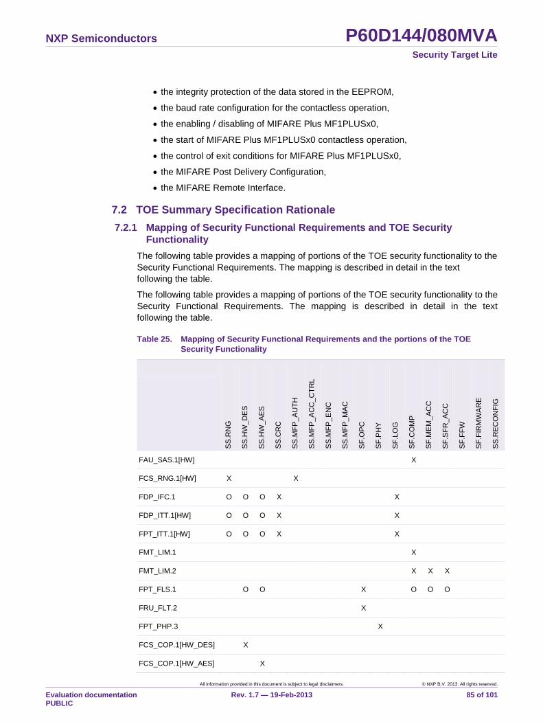
NXP Semiconductors P60D144/080MVA Security Target Lite
All information provided in this document is subject to legal disclaimers. © NXP B.V. 2013. All rights reserved.
Evaluation documentation PUBLIC
Rev. 1.7 — 19-Feb-2013 85 of 101
the integrity protection of the data stored in the EEPROM,
the baud rate configuration for the contactless operation,
the enabling / disabling of MIFARE Plus MF1PLUSx0,
the start of MIFARE Plus MF1PLUSx0 contactless operation,
the control of exit conditions for MIFARE Plus MF1PLUSx0,
the MIFARE Post Delivery Configuration,
the MIFARE Remote Interface.
7.2 TOE Summary Specification Rationale
7.2.1 Mapping of Security Functional Requirements and TOE Security
Functionality
The following table provides a mapping of portions of the TOE security functionality to the
Security Functional Requirements. The mapping is described in detail in the text
following the table.
The following table provides a mapping of portions of the TOE security functionality to the
Security Functional Requirements. The mapping is described in detail in the text
following the table.
Table 25. Mapping of Security Functional Requirements and the portions of the TOE
Security Functionality
SS
.RN
G
SS
.HW
_D
ES
SS
.HW
_A
ES
SS
.CR
C
SS
.MF
P_A
UT
H
SS
.MF
P_A
CC
_C
TR
L
SS
.MF
P_E
NC
SS
.MF
P_M
AC
SF
.OP
C
SF
.PH
Y
SF
.LO
G
SF
.CO
MP
SF
.ME
M_
AC
C
SF
.SF
R_A
CC
SF
.FF
W
SF
.FIR
MW
AR
E
SS
.RE
CO
NF
IG
FAU_SAS.1[HW] X
FCS_RNG.1[HW] X X
FDP_IFC.1 O O O X X
FDP_ITT.1[HW] O O O X X
FPT_ITT.1[HW] O O O X X
FMT_LIM.1 X
FMT_LIM.2 X X X
FPT_FLS.1 O O X O O O
FRU_FLT.2 X
FPT_PHP.3 X
FCS_COP.1[HW_DES] X
FCS_COP.1[HW_AES] X
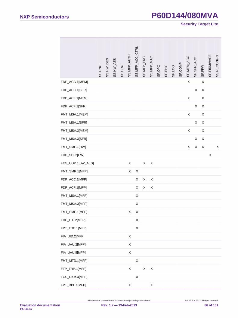
NXP Semiconductors P60D144/080MVA Security Target Lite
All information provided in this document is subject to legal disclaimers. © NXP B.V. 2013. All rights reserved.
Evaluation documentation PUBLIC
Rev. 1.7 — 19-Feb-2013 86 of 101
SS
.RN
G
SS
.HW
_D
ES
SS
.HW
_A
ES
SS
.CR
C
SS
.MF
P_A
UT
H
SS
.MF
P_A
CC
_C
TR
L
SS
.MF
P_E
NC
SS
.MF
P_M
AC
SF
.OP
C
SF
.PH
Y
SF
.LO
G
SF
.CO
MP
SF
.ME
M_
AC
C
SF
.SF
R_A
CC
SF
.FF
W
SF
.FIR
MW
AR
E
SS
.RE
CO
NF
IG
FDP_ACC.1[MEM] X X
FDP_ACC.1[SFR] X X
FDP_ACF.1[MEM] X X
FDP_ACF.1[SFR] X X
FMT_MSA.1[MEM] X X
FMT_MSA.1[SFR] X X
FMT_MSA.3[MEM] X X
FMT_MSA.3[SFR] X X
FMT_SMF.1[HW] X X X X
FDP_SDI.2[HW] X
FCS_COP.1[SW_AES] X X X
FMT_SMR.1[MFP] X X
FDP_ACC.1[MFP] X X X
FDP_ACF.1[MFP] X X X
FMT_MSA.1[MFP] X
FMT_MSA.3[MFP] X
FMT_SMF.1[MFP] X X
FDP_ITC.2[MFP] X
FPT_TDC.1[MFP] X
FIA_UID.2[MFP] X
FIA_UAU.2[MFP] X
FIA_UAU.5[MFP] X
FMT_MTD.1[MFP] X
FTP_TRP.1[MFP] X X X
FCS_CKM.4[MFP] X
FPT_RPL.1[MFP] X X
NXP Semiconductors P60D144/080MVA Security Target Lite
All information provided in this document is subject to legal disclaimers. © NXP B.V. 2013. All rights reserved.
Evaluation documentation PUBLIC
Rev. 1.7 — 19-Feb-2013 87 of 101
"X" in the table above means that the specific portion of the TOE security functionality
realises the functionality required by the respective Security Functional Requirement. “O”
in the table above means that the specific portion of the TOE security functionality
supports the functionality required by the respective Security Functional Requirement.
As already stated in the definition of the portions of the TOE security functionality there
are additional security mechanisms, which can contribute to security functionality when
they are appropriately controlled by the Security IC Embedded Software. E.g. the Fame2
coprocessor can be used to implement leakage resistant asymmetric cryptographic
algorithms.
MIFARE Plus MF1PLUSx0 is part of the IC Dedicated Software and is therefore
separated from the Security IC Embedded Software by memory partitioning according to
SF.MEM_ACC, SF.FFW and by CPU mode control according to SF.SFR_ACC and
SF.COMP. The data exchange areas are also controlled by SF.MEM_ACC and SF.FFW
and must be configured by the Security IC Embedded Software.
7.2.2 Rationale for the portions of the TOE security functionality
(Details deleted here, only available in the full version of the Security Target.)
7.2.3 Security architectural information
Since this Security Target claims the assurance requirement ASE_TSS.2 security
architectural information on a very high level is supposed to be included in the TSS to
inform potential customers on how the TOE protects itself against interference, logical
tampering and bypass. In the security architecture context, this covers the aspects self-
protection and non-bypassability.
(Deleted here, only available in the full version of the Security Target.)
NXP Semiconductors P60D144/080MVA Security Target Lite
All information provided in this document is subject to legal disclaimers. © NXP B.V. 2013. All rights reserved.
Evaluation documentation PUBLIC
Rev. 1.7 — 19-Feb-2013 88 of 101
8. Annexes
8.1 Further Information contained in the PP
Chapter 7 of the PP “Security IC Protection Profile” [6] provides further information.
Section 7.1 in [6] describes the development and production process of Security ICs
including a detailed life-cycle description and a description of the assets of the IC
Designer/Manufacturer. Section 7.2 in [6] comprises security aspects of the Security IC
Embedded Software, i.e. further information regarding A.Resp-Appl and examples of
specific Functional Requirements for the Security IC Embedded Software. Section 7.3 in
[6] contains examples of Attack Scenarios.
8.2 Glossary and Vocabulary
Administrator (in the sense of the Common Criteria) The TOE may
provide security functionality which can or need to be
administrated (i) by the Security IC Embedded
Software or (ii) using services of the TOE after
delivery to Phases 4-6. Then a privileged user (in the
sense of the Common Criteria, refer to definition
below) becomes an administrator.
Application Data All data managed by the Security IC Embedded
Software in the application context. Application data
comprise all data in the final Security IC.
Boot Mode CPU mode of the TOE dedicated to start-up and
reset of the TOE. This mode is not accessible for the
Security IC Embedded Software.
Composite Product Integrator Role installing or finalising the IC
Embedded Software and the applications on platform
transforming the TOE into the unpersonalised
Composite Product after TOE delivery
The TOE Manufacturer may implement IC Embedded
Software delivered by the Security IC Embedded
Software Developer before TOE delivery (e.g. if the
IC Embedded Software is implemented in ROM or is
stored in the non-volatile memory as service provided
by the IC Manufacturer or IC Packaging
Manufacturer).
Composite Product Manufacturer The Composite Product Manufacturer has the
following roles (i) the Security IC Embedded Software
Developer (Phase 1), (ii) the Composite Product
Integrator (Phase 5) and (iii) the Personaliser (Phase
6). If the TOE is delivered after Phase 3 in form of
wafers or sawn wafers (dice) he has the role of the IC
Packaging Manufacturer (Phase 4) in addition.
The customer of the TOE Manufacturer, who receives
the TOE during TOE Delivery. The Composite
Product Manufacturer includes the Security IC
Embedded Software developer and all roles after
NXP Semiconductors P60D144/080MVA Security Target Lite
All information provided in this document is subject to legal disclaimers. © NXP B.V. 2013. All rights reserved.
Evaluation documentation PUBLIC
Rev. 1.7 — 19-Feb-2013 89 of 101
TOE Delivery up to Phase 6 (refer to [6], Figure 2 on
page 240H10 and Section 7.1.1)
CPU mode Mode in which the CPU operates. The TOE supports
five CPU modes, which are Boot Mode, Test Mode,
Firmware Mode, System Mode and User Mode.
DESFire DESFire EV1 emulation, names the DESFire
Operating System as part of the IC Dedicated
Software.
exception interrupt Non-maskable interrupt of program execution
jumping to fixed addresses (depending on the
exception source) and enabling System Mode.
Sources of exceptions are hardware breakpoints,
single fault injection detections, illegal instructions,
stack overflows, unauthorised system call vector
calls, execution of RETI instruction in User Mode, and
the MMU exceptions access violation and access
collision.
FabKey Area A memory area in the EEPROM containing data,
which are programmed during testing by the IC
Manufacturer. The amount of data and the type of
information can be selected by the customer.
Firmware Mode CPU mode of the TOE dedicated to execution of the
Emulation Framework with MIFARE Plus
MF1PLUSx0, which is part of the IC Dedicated
Support Software. This mode is not accessible for the
Security IC Embedded Software.
End-consumer User of the Composite Product in Phase 7
Initialisation Data Initialisation Data defined by the TOE Manufacturer to
identify the TOE and to keep track of the Security IC‟s
production and further life-cycle phases are
considered as belonging to the TSF data. These data
are for instance used for traceability and for TOE
identification (identification data).
Integrated Circuit (IC) Electronic component(s) designed to perform
processing and/or memory functions.
kByte(s) / (KB) kByte (KB) used with k=1024 (K=1024)
Memory IC hardware component, that stores code and/or
data, i.e. ROM, RAM or EEPROM of the TOE.
Memory Management Unit The MMU maps the virtual addresses used by the
CPU into the physical addresses of RAM, ROM and
EEPROM. This mapping is done based on (a)
memory partitioning and (b) memory segments for
code running in User Mode. Memory partitioning is
fixed, whereas up to 64 memory segments can be
configured individually. Each segment can be (i)
positioned and sized (ii) enabled and disabled, (iii)
configured for access rights in terms of read, write
NXP Semiconductors P60D144/080MVA Security Target Lite
All information provided in this document is subject to legal disclaimers. © NXP B.V. 2013. All rights reserved.
Evaluation documentation PUBLIC
Rev. 1.7 — 19-Feb-2013 90 of 101
and execute in User Mode and (iv) configured for
User Mode access rights to Special Function
Registers related to hardware components of code
executed in this segment.
Memory Segment Address space provided by the Memory Management
Unit according to the configuration in the MMU
Segment Table. A memory segment defines a
memory area, are accessible for code running in User
Mode. Memory segments may address RAM, ROM
and EEPROM.
MIFARE Contactless smartcard interface standard complying
with ISO/IEC 14443 A.
MIFARE Plus MIFARE Plus emulation, names the MIFARE Plus
Operating System as part of the IC Dedicated
Software.
MMU Segment Table This structure defines the memory segments for code
running in User Mode, which are controlled by the
MMU. The structure can be located anywhere in the
memory that is available in System Mode. It also
contains User Mode access rights to Special Function
Registers related to hardware components of code
executed in each segment.
Pre-personalisation Data Any data supplied by the Card Manufacturer that is
injected into the non-volatile memory by the
Integrated Circuits manufacturer (Phase 3). These
data are for instance used for traceability and/or to
secure shipment between phases.
S²C Smartcard interface standard complying with ISO/IEC
18092.
Security IC (as used in the PP [6]) Composition of TOE, Security
IC Embedded Software, User Data and package
(Security IC carrier).
IC Dedicated Software IC proprietary software embedded in a Security IC
(also known as IC firmware) and developed by the IC
Developer. Such software is required for testing
purpose (IC Dedicated Test Software) but may
provide additional services to facilitate usage of the
hardware and/or to provide additional services (IC
Dedicated Support Software).
IC Dedicated Support Software
That part of the IC Dedicated Software (refer to
above) which provides functions after TOE Delivery.
The usage of parts of the IC Dedicated Software
might be restricted to certain phases.
IC Dedicated Test Software
NXP Semiconductors P60D144/080MVA Security Target Lite
All information provided in this document is subject to legal disclaimers. © NXP B.V. 2013. All rights reserved.
Evaluation documentation PUBLIC
Rev. 1.7 — 19-Feb-2013 91 of 101
That part of the IC Dedicated Software (refer to
above) which is used to test the TOE before TOE
Delivery but which does not provide any functionality
thereafter.
Security IC Embedded Software Software embedded in a Security IC and normally not
being developed by the IC Designer. The Security IC
Embedded Software is designed in Phase 1 and
embedded into the Security IC in Phase 3 or in later
phases of the Security IC product life-cycle.
Some part of that software may actually implement a
Security IC application others may provide standard
services. Nevertheless, this distinction does not
matter here so that the Security IC Embedded
Software can be considered as being application
dependent whereas the IC Dedicated Software is
definitely not.
Security IC Product Composite product which includes the Security
Integrated Circuit (i.e. the TOE) and the Embedded
Software and is evaluated as composite target of
evaluation in the sense of the Supporting Document
Security Rows Top-most 256 bytes of the EEPROM memory
reserved for configuration purposes as well as
dedicated memory area for the Security IC
Embedded Software to store life-cycle information
about the TOE.
Special Function Registers Registers used to access and configure the functions
for communication with an external interface device,
the cryptographic coprocessors for Triple-DES or
AES, the Fame2 coprocessor for basic arithmetic
functions to perform asymmetric cryptographic
algorithms, the random numbers generator and chip
configuration.
Super System Mode This term represents either Boot Mode, Test Mode or
Firmware Mode.
System Mode CPU mode of the TOE with unrestricted access to the
hardware resources. The Memory Management Unit
can be configured in System Mode.
Test Features All features and functions (implemented by the IC
Dedicated Test Software and/or hardware) which are
designed to be used before TOE Delivery only and
delivered as part of the TOE.
Test Mode CPU mode of the TOE for its configuration and
execution of the IC Dedicated Test Software. The
Test Mode is permanently and irreversible disabled
after production testing. Specific Special Function
Registers are accessible in Test Mode for test
purposes.
NXP Semiconductors P60D144/080MVA Security Target Lite
All information provided in this document is subject to legal disclaimers. © NXP B.V. 2013. All rights reserved.
Evaluation documentation PUBLIC
Rev. 1.7 — 19-Feb-2013 92 of 101
TOE Delivery The period when the TOE is delivered which is (refer
to [6], Figure 2 on page 242H10) either (i) after Phase
3 (or before Phase 4) if the TOE is delivered in form
of wafers or sawn wafers (dice) or (ii) after Phase 4
(or before Phase 5) if the TOE is delivered in form of
packaged products.
TOE Manufacturer The TOE Manufacturer must ensure that all
requirements for the TOE (as defined in [6], Section
1.2.2) and its development and production
environment are fulfilled (refer to [6], Figure 2 on
page 10).
The TOE Manufacturer has the following roles: (i) IC
Developer (Phase 2) and (ii) IC Manufacturer (Phase
3). If the TOE is delivered after Phase 4 in form of
packaged products, he has the role of the (iii) IC
Packaging Manufacturer (Phase 4) in addition.
TSF data Data created by and for the TOE, which might affect
the operation of the TOE. This includes information
about the TOE‟s configuration, if any is coded in non
volatile non-programmable memories (ROM), in
specific circuitry, in non-volatile programmable
memories (for instance EEPROM) or a combination
thereof.
User (in the sense of the Common Criteria) The TOE
serves as a platform for the Security IC Embedded
Software. Therefore, the “user” of the TOE (as used
in the Common Criteria assurance class AGD:
guidance) is the Security IC Embedded Software.
Guidance is given for the Security IC Embedded
Software Developer.
On the other hand the Security IC (with the TOE as a
major element) is used in a terminal where
communication is performed through the ISO/IEC
interface provided by the TOE. Therefore, another
“user” of the TOE is the terminal (with its software).
User Data All data managed by the Security IC Embedded
Software in the application context. User data
comprise all data in the final Security IC except the
TSF data.
User Mode CPU mode of the TOE. Access to memories is
controlled by the Memory Management Unit. Access
to Special Function Registers is restricted.
8.3 List of Abbreviations
ACK Acknowledge
CC Common Criteria Version 3.1
NXP Semiconductors P60D144/080MVA Security Target Lite
All information provided in this document is subject to legal disclaimers. © NXP B.V. 2013. All rights reserved.
Evaluation documentation PUBLIC
Rev. 1.7 — 19-Feb-2013 93 of 101
CIU Contactless Interface Unit
CPU Central Processing Unit
CPU_CSR CPU Status Register
DEA Data Encryption Algorithm
DES Data Encryption Standard
DRNG Deterministic Random Number Generator
EAL Evaluation Assurance Level
ECC Elliptic Curve Cryptography
FVEC Firmware VECtor
FOS Firmware Operating System
IC Integrated circuit
IT Information Technology
MFP MIFARE Plus
MMU Memory Management Unit
MX Memory eXtension
NAK Not ACK
NDA Non Disclosure Agreement
NFC Near Field Communication
PDC Post Delivery Configuration
PKC Public Key Cryptography
PP Protection Profile
SAR Security Assurance Requirement
SFR as abbreviation of the CC term: Security
Functional Requirement, as abbreviation of the
technical term of the SmartMX2 family: Special
Function Register97
SIM Subscriber Identity Module
SOF Strength of Function
SF Security Feature
97 To avoid confusion this Security Target does not use SFR as abbreviation for Special Function
Register in the explanatory text. However, the abbreviation is used in objective or security
functionality identifiers and to distinguish iterations.
NXP Semiconductors P60D144/080MVA Security Target Lite
All information provided in this document is subject to legal disclaimers. © NXP B.V. 2013. All rights reserved.
Evaluation documentation PUBLIC
Rev. 1.7 — 19-Feb-2013 94 of 101
SS Security Service
ST Security Target
TOE Target of Evaluation
TRNG True Random Number Generator
TSF TOE Security Functionality
TSFI TSF Interface
TSP TOE Security Policy
UART Universal Asynchronous Receiver and Transmitter
NXP Semiconductors P60D144/080MVA Security Target Lite
All information provided in this document is subject to legal disclaimers. © NXP B.V. 2013. All rights reserved.
Evaluation documentation PUBLIC
Rev. 1.7 — 19-Feb-2013 95 of 101
9. Bibliography
9.1.1 Evaluation Documents
[1] Common Criteria for Information Technology Security Evaluation, Part 1:
Introduction and general model, Version 3.1, Revision 3, July 2009, CCMB-2009-
07-001
[2] Common Criteria for Information Technology Security Evaluation, Part 2: Security
functional components, Version 3.1, Revision 3, July 2009, CCMB-2009-07-002
[3] Common Criteria for Information Technology Security Evaluation, Part 3: Security
assurance components, Version 3.1, Revision 3, July 2009, CCMB-2009-07-003
[4] Common Methodology for Information Technology Security Evaluation, Evaluation
Methodology, Version 3.1, Revision 3, July 2009, CCMB-2009-07-004
[5] Supporting Document Mandatory Technical Document Application of Attack
Potential to Smartcards, Version 2.7, Revision 1, March 2009, CCDB-2009-03-001
[6] Security IC Platform Protection Profile, Version 1.0, registered and certified by
Bundesamt fuer Sicherheit in der Informationstechnik (BSI) under the reference
BSI-PP-0035
[7] Anwendungshinweise und Interpretationen zum Schema, AIS31:
Funktionalitaetsklassen und Evaluationsmethodologie fuer physikalische
Zufallszahlengeneratoren, Version 2.1, 02.12.2011, Bundesamt fuer Sicherheit in
der Informationstechnik
[8] A proposal for: Functionality classes for random number generators, Version 2.0,
18 September 2011
9.1.2 Developer Documents
[9] Product Data Sheet SmartMX2 family P60D080/144 and P60C080/144, Secure
high performance smart card controller, NXP Semiconductors, Business Unit
Identification
[10] Instruction Set for the SmartMX2 family, Secure smart card controller, NXP
Semiconductors, Business Unit Identification
[11] NXP Secure Smart Card Controller P60x080/P60x144PVA, Guidance and
Operation Manual, NXP Semiconductors, Business Unit Identification
[12] SmartMX2 family P60D080/144 VA and P60C080/144 VA Wafer and delivery
specification, NXP Semiconductors, Business Unit Identification
[13] Order Entry Form P60D144, NXP Semiconductors, Business Unit Identification,
online document
[14] Order Entry Form P60D080, NXP Semiconductors, Business Unit Identification,
online document
[15] MIFARE Plus Functionality of implementations on smart card controllers, NXP
Semiconductors, Business Unit Identification
[16] SmartMX2 family, Post Delivery Configuration (PDC), Product data sheet
addendum, NXP Semiconductors, Business Unit Identification
[17] SmartMX2 family Chip Health Mode (CHM), Product data sheet addendum, NXP
Semiconductors, Business Unit Identification
NXP Semiconductors P60D144/080MVA Security Target Lite
All information provided in this document is subject to legal disclaimers. © NXP B.V. 2013. All rights reserved.
Evaluation documentation PUBLIC
Rev. 1.7 — 19-Feb-2013 96 of 101
[18] SmartMX2 family Firmware Interface Specification, Product data sheet addendum,
NXP Semiconductors, Business Unit Identification
[19] MIFARE Plus MF1PLUSx0 Guidance, Delivery and Operation Manual, NXP Secure
Smart Card Controller P60xeeey with MF1PLUSx0, NXP Semiconductors,
Business Unit Identification
9.1.3 Other Documents
[20] FIPS PUB 46-3 FEDERAL INFORMATION PROCESSING STANDARDS
PUBLICATION DATA ENCRYPTION STANDARD (DES) Reaffirmed 1999 October
25
[21] FIPS PUB 197 FEDERAL INFORMATION PROCESSING STANDARDS
PUBLICATION, ADVANCED ENCRYPTION STANDARD (AES), National Institute
of Standards and Technology, 2001 November 26
[22] PKCS 1: RSA Cryptography Specifications, Version 2.0. RSA Laboratories,
September 1998
[23] ISO/IEC 7816-2:1996 Information technology - Identification cards - Integrated
circuit(s) cards with contacts - Part 2: Dimensions and location of contacts
[24] ISO/IEC 7816-3:1997 Information technology - Identification cards - Integrated
circuit(s) cards with contacts - Part 3: Electronic signals and transmission protocols
[25] ISO/IEC 14443-3:2001: Identification cards - Contactless integrated circuit(s) cards
- Proximity cards - Part 3: Initialization and anticollision
[26] ISO/IEC 14443-4:2001: Identification cards - Contactless integrated circuit(s) cards
- Proximity cards - Part 4: Transmission protocol
[27] ISO/IEC 18092:2004: Information technology - Telecommunications and
information exchange between systems - Near Field Communication - Interface
and Protocol (NFCIP-1)
[28] NIST Special Publication 800-38A: Recommendation for Block Cipher Modes of
Operation: Methods and Techniques, December 2001, Morris Dworkin, National
Institute of Standards and Technology
[29] NIST Special Publication 800-38B: Recommendation for Block Cipher Modes of
Operation: The CMAC Mode for Authentication, May 2005, Morris Dworkin,
National Institute of Standards and Technology
NXP Semiconductors P60D144/080MVA Security Target Lite
All information provided in this document is subject to legal disclaimers. © NXP B.V. 2013. All rights reserved.
Evaluation documentation PUBLIC
Rev. 1.7 — 19-Feb-2013 97 of 101
10. Legal information
10.1 Definitions Draft — The document is a draft version only. The content is still under
internal review and subject to formal approval, which may result in
modifications or additions. NXP Semiconductors does not give any
representations or warranties as to the accuracy or completeness of
information included herein and shall have no liability for the consequences
of use of such information.
10.2 Disclaimers Limited warranty and liability — Information in this document is believed to
be accurate and reliable. However, NXP Semiconductors does not give any
representations or warranties, expressed or implied, as to the accuracy or
completeness of such information and shall have no liability for the
consequences of use of such information.
In no event shall NXP Semiconductors be liable for any indirect, incidental,
punitive, special or consequential damages (including without limitation
lost profits, lost savings, business interruption, costs related to the removal
or replacement of any products or rework charges) whether or not such
damages are based on tort (including negligence), warranty, breach of
contract or any other legal theory.
Notwithstanding any damages that customer might incur for any reason
whatsoever, NXP Semiconductors‟ aggregate and cumulative liability
towards customer for the products described herein shall be limited in
accordance with the Terms and conditions of commercial sale of NXP
Semiconductors.
Right to make changes — NXP Semiconductors reserves the right to make
changes to information published in this document, including without
limitation specifications and product descriptions, at any time and without
notice. This document supersedes and replaces all information supplied prior
to the publication hereof.
Suitability for use — NXP Semiconductors products are not designed,
authorized or warranted to be suitable for use in medical, military, aircraft,
space or life support equipment, nor in applications where failure or
malfunction of a NXP Semiconductors product can reasonably be expected
to result in personal injury, death or severe property or environmental
damage. NXP Semiconductors accepts no liability for inclusion and/or use of
NXP Semiconductors products in such equipment or applications and
therefore such inclusion and/or use is at the customer‟s own risk.
Applications — Applications that are described herein for any of these
products are for illustrative purposes only. NXP Semiconductors makes no
representation or warranty that such applications will be suitable for the
specified use without further testing or modification.
NXP Semiconductors does not accept any liability related to any default,
damage, costs or problem which is based on a weakness or default in the
customer application/use or the application/use of customer‟s third party
customer(s) (hereinafter both referred to as “Application”). It is customer‟s
sole responsibility to check whether the NXP Semiconductors product is
suitable and fit for the Application planned. Customer has to do all necessary
testing for the Application in order to avoid a default of the Application and
the product. NXP Semiconductors does not accept any liability in this
respect.
Export control — This document as well as the item(s) described herein
may be subject to export control regulations. Export might require a prior
authorization from national authorities.
10.3 Licenses
ICs with DPA Countermeasures functionality
NXP ICs containing functionality
implementing countermeasures to
Differential Power Analysis and Simple
Power Analysis are produced and sold
under applicable license from
Cryptography Research, Inc.
10.4 Patents Notice is herewith given that the subject device uses one or more of the
following patents and that each of these patents may have corresponding
patents in other jurisdictions.
<Patent ID> — owned by <Company name>
10.5 Trademarks Notice: All referenced brands, product names, service names and
trademarks are property of their respective owners.
FabKey — is a trademark of NXP B.V.
MIFARE — is a trademark of NXP B.V.
MIFARE Plus — is a trademark of NXP B.V.
SmartMx — is a trademark of NXP B.V.
NXP Semiconductors P60D144/080MVA Security Target Lite
All information provided in this document is subject to legal disclaimers. © NXP B.V. 2013. All rights reserved.
Evaluation documentation PUBLIC
Rev. 1.7 — 19-Feb-2013 98 of 101
11. List of figures
Fig 1. Block Diagram of P60D144/080MVA ................ 5 Fig 2. Logical boundary of the TOE .......................... 17
NXP Semiconductors P60D144/080MVA Security Target Lite
All information provided in this document is subject to legal disclaimers. © NXP B.V. 2013. All rights reserved.
Evaluation documentation PUBLIC
Rev. 1.7 — 19-Feb-2013 99 of 101
12. List of tables
Table 1. Components of the TOE ................................... 6 Table 2. Evaluated major configuration options .............. 8 Table 3. Evaluated minor configuration options .............. 8 Table 4. Hardware Post Delivery Configuration for
P60D144MVA / P60D080MVA ........................ 12 Table 6. Variable definitions for commercial type names
........................................................................ 13 Table 7. Supported Package Types .............................. 13 Table 8. CPU modes of the TOE .................................. 14 Table 9. Threats defined by the PP [6] .......................... 25 Table 10. Assumptions defined in the PP [6] .................. 28 Table 12. Security objectives for the Security IC
Embedded Software development environment,
taken from the PP [6] ...................................... 32 Table 13. Security objectives for the operational
environment, taken from the PP [6] ................. 33 Table 14. Security Objectives versus Assumptions,
Threats or Policies (PP) .................................. 34 Table 15. Additional Security Objectives versus
Assumptions, Threats or Policies .................... 35 Table 17. SFRs taken from the PP [6] ............................ 40 Table 18. Security Assurance Requirements .................. 64 Table 19. Security Assurance Requirements, overview of
differences of refinements ............................... 65 Table 20. Security Requirements versus Security
Objectives ....................................................... 66 Table 21. Mapping of security objectives and requirements
........................................................................ 67 Table 23. Dependencies of security functional
requirements ................................................... 71 Table 24. Dependencies of security functional
requirements (MIFARE Plus MF1PLUSx0) ..... 72
NXP Semiconductors P60D144/080MVA Security Target Lite
Please be aware that important notices concerning this document and the product(s) described herein, have been included in the section 'Legal information'.
© NXP B.V. 2013. All rights reserved.
For more information, please visit: http://www.nxp.com
For sales office addresses, please send an please send an email to: [email protected]
Date of release: 19-Feb-2013
Document identifier:
13. Contents
1. ST Introduction .................................................... 3 1.1 ST Reference ..................................................... 3 1.2 TOE Reference .................................................. 3 1.3 TOE Overview .................................................... 3 1.3.1 Usage and major security functionality of the
TOE .................................................................... 3 1.3.2 TOE type ............................................................ 5 1.3.3 Required non-TOE hardware/software/firmware 5 1.4 TOE Description ................................................. 5 1.4.1 Physical Scope of TOE ...................................... 5 1.4.1.1 TOE components ............................................... 6 1.4.2 Evaluated configurations .................................... 7 1.4.2.1 Major configuration options ................................ 7 1.4.2.2 Minor configuration options ................................ 8 1.4.2.3 Post Delivery Configuration .............................. 11 1.4.2.4 Evaluated package types ................................. 13 1.4.3 Logical Scope of TOE ...................................... 14 1.4.3.1 Hardware Description ....................................... 14 1.4.3.2 Software Description ........................................ 17 1.4.3.3 Documentation ................................................. 19 1.4.4 Security during Development and Production .. 20 1.4.5 TOE Intended Usage ....................................... 21 1.4.6 Interface of the TOE ......................................... 22 2. Conformance Claims ........................................ 23 2.1 CC Conformance Claim ................................... 23 2.2 Package claim .................................................. 23 2.3 PP claim ........................................................... 23 2.4 Conformance Claim Rationale ......................... 24 3. Security Problem Definition ............................. 25 3.1 Description of Assets ....................................... 25 3.2 Threats ............................................................. 25 3.3 Organisational Security Policies ....................... 27 3.4 Assumptions ..................................................... 28 4. Security Objectives ........................................... 30 4.1 Security Objectives for the TOE ....................... 30 4.2 Security Objectives for the Security IC
Embedded Software development Environment
......................................................................... 32 4.3 Security Objectives for the Operational
Environment ..................................................... 33 4.4 Security Objectives Rationale .......................... 34 5. Extended Components Definition .................... 39 6. Security Requirements ..................................... 40 6.1 Security Functional Requirements ................... 40 6.1.1 SFRs of the Protection Profile .......................... 40
6.1.2 Additional SFRs regarding cryptographic
functionality ...................................................... 44 6.1.3 Additional SFRs regarding access control ........ 46 6.1.4 Additional SFRs for the MIFARE Plus
MF1PLUSx0 ..................................................... 56 6.2 Security Assurance Requirements ................... 64 6.2.1 Refinements of the Security Assurance
Requirements ................................................... 65 6.2.1.1 Refinements regarding CM scope (ALC_CMS) 65 6.2.1.2 Refinements regarding functional specification
(ADV_FSP) ....................................................... 65 6.3 Security Requirements Rationale ..................... 66 6.3.1 Rationale for the security functional requirements
......................................................................... 66 6.3.2 Dependencies of security functional
requirements .................................................... 71 6.3.3 Rationale for the Security Assurance
Requirements ................................................... 73 6.3.4 Security Requirements are internally Consistent
......................................................................... 73 7. TOE Summary Specification ............................. 75 7.1 Portions of the TOE Security Functionality ....... 75 7.1.1 Security Services .............................................. 75 7.1.2 Security Features ............................................. 78 7.2 TOE Summary Specification Rationale ............ 85 7.2.1 Mapping of Security Functional Requirements
and TOE Security Functionality ........................ 85 7.2.2 Rationale for the portions of the TOE security
functionality ...................................................... 87 7.2.3 Security architectural information ..................... 87 8. Annexes.............................................................. 88 8.1 Further Information contained in the PP ........... 88 8.2 Glossary and Vocabulary ................................. 88 8.3 List of Abbreviations ......................................... 92 9. Bibliography ....................................................... 95 9.1.1 Evaluation Documents...................................... 95 9.1.2 Developer Documents ...................................... 95 9.1.3 Other Documents ............................................. 96 10. Legal information .............................................. 97 10.1 Definitions ......................................................... 97 10.2 Disclaimers ....................................................... 97 10.3 Licenses ........................................................... 97 10.4 Patents ............................................................. 97 10.5 Trademarks ...................................................... 97 11. List of figures ..................................................... 98
NXP Semiconductors P60D144/080MVA Security Target Lite
Please be aware that important notices concerning this document and the product(s) described herein, have been included in the section 'Legal information'.
© NXP B.V. 2013. All rights reserved.
For more information, please visit: http://www.nxp.com
For sales office addresses, please send an please send an email to: [email protected]
Date of release: 19-Feb-2013
Document identifier:
12. List of tables ...................................................... 99 13. Contents ........................................................... 100