Embed Size (px)
Citation preview
© Semiconductor Components Industries, LLC, 2016
July, 2021 − Rev. 61 Publication Order Number:
NXH100B120H3Q0/D
Dual Boost Power Module
NXH100B120H3Q0
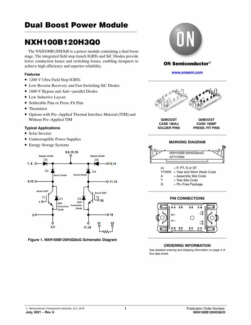
The NXH100B120H3Q0 is a power module containing a dual booststage. The integrated field stop trench IGBTs and SiC Diodes providelower conduction losses and switching losses, enabling designers toachieve high efficiency and superior reliability.
Features• 1200 V Ultra Field Stop IGBTs
• Low Reverse Recovery and Fast Switching SiC Diodes
• 1600 V Bypass and Anti−parallel Diodes
• Low Inductive Layout
• Solderable Pins or Press−Fit Pins
• Thermistor
• Options with Pre−Applied Thermal Interface Material (TIM) andWithout Pre−Applied TIM
Typical Applications• Solar Inverter
• Uninterruptible Power Supplies
• Energy Storage Systems
Figure 1. NXH100B120H3Q0xG Schematic Diagram
www.onsemi.com
MARKING DIAGRAM
Q0BOOSTCASE 180AJ
SOLDER PINS
PIN CONNECTIONS
xx = P, PT, S or STYYWW = Year and Work Week CodeA = Assembly Site CodeT = Test Site CodeG = Pb−Free Package
Q0BOOSTCASE 180BF
PRESS−FIT PINS
NXH100B120H3Q0xxGATYYWW
See detailed ordering and shipping information on page 4 ofthis data sheet.
ORDERING INFORMATION

NXH100B120H3Q0
www.onsemi.com2
ABSOLUTE MAXIMUM RATINGS (Note 1) TJ = 25°C Unless Otherwise Noted
Rating Symbol Value Unit
BOOST IGBT
Collector−Emitter Voltage VCES 1200 V
Gate−Emitter Voltage VGE ±20 V
Continuous Collector Current @ TC < 80°C (TJ = 175°C) IC1 61 A
Continuous Collector Current @ TC < 102°C (TJ = 175°C) IC2 50 A
Pulsed Collector Current (TJ = 175°C) ICpulse 150 A
Maximum Power Dissipation @ TC = 80°C (TJ = 175°C) Ptot 186 W
Minimum Operating Junction Temperature TJMIN −40 °C
Maximum Operating Junction Temperature TJMAX 150 °C
BOOST DIODE
Peak Repetitive Reverse Voltage VRRM 1200 V
Continuous Forward Current @ TC < 80°C (TJ = 175°C) IF1 34 A
Continuous Forward Current @ TC < 132°C (TJ = 175°C) IF2 20 A
Maximum Power Dissipation @ TC = 80°C (TJ = 175°C) Ptot 114 W
Surge Forward Current (60 Hz single half−sine wave) IFSM 185 A
I2t − value (60 Hz single half−sine wave) I2t 142 A2s
Minimum Operating Junction Temperature TJMIN −40 °C
Maximum Operating Junction Temperature TJMAX 150 °C
BYPASS DIODE / IGBT PROTECTION DIODE
Peak Repetitive Reverse Voltage VRRM 1600 V
Continuous Forward Current @ TC < 80°C (TJ = 175°C) IF1 58 A
Continuous Forward Current @ TC < 141°C (TJ = 175°C) IF2 25 A
Repetitive Peak Forward Current (TJ = 175°C, tp limited by TJmax) IFRM 75 A
Maximum Power Dissipation @ TC = 80°C (TJ = 175°C) Ptot 91 W
Minimum Operating Junction Temperature TJMIN −40 °C
Maximum Operating Junction Temperature TJMAX 150 °C
THERMAL PROPERTIES
Storage Temperature range Tstg −40 to 125 °C
INSULATION PROPERTIES
Isolation test voltage, t = 1 sec, 60 Hz Vis 3000 VRMS
Creepage distance 12.7 mm
Stresses exceeding those listed in the Maximum Ratings table may damage the device. If any of these limits are exceeded, device functionalityshould not be assumed, damage may occur and reliability may be affected.1. Refer to ELECTRICAL CHARACTERISTICS, RECOMMENDED OPERATING RANGES and/or APPLICATION INFORMATION for Safe
Operating parameters.
RECOMMENDED OPERATING RANGES
Rating Symbol Min Max Unit
Module Operating Junction Temperature TJ −40 150 °C
Functional operation above the stresses listed in the Recommended Operating Ranges is not implied. Extended exposure to stresses beyondthe Recommended Operating Ranges limits may affect device reliability.
NXH100B120H3Q0
www.onsemi.com3
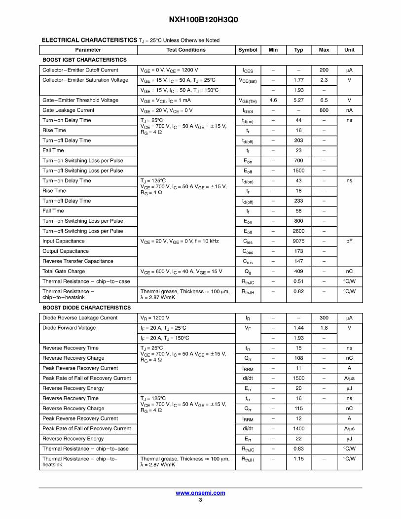
ELECTRICAL CHARACTERISTICS TJ = 25°C Unless Otherwise Noted
Parameter Test Conditions Symbol Min Typ Max Unit
BOOST IGBT CHARACTERISTICS
Collector−Emitter Cutoff Current VGE = 0 V, VCE = 1200 V ICES – – 200 �A
Collector−Emitter Saturation Voltage VGE = 15 V, IC = 50 A, TJ = 25°C VCE(sat) – 1.77 2.3 V
VGE = 15 V, IC = 50 A, TJ = 150°C – 1.93 –
Gate−Emitter Threshold Voltage VGE = VCE, IC = 1 mA VGE(TH) 4.6 5.27 6.5 V
Gate Leakage Current VGE = 20 V, VCE = 0 V IGES – − 800 nA
Turn−on Delay Time TJ = 25°CVCE = 700 V, IC = 50 A VGE = ±15 V, RG = 4 �
td(on) – 44 – ns
Rise Time tr – 16 –
Turn−off Delay Time td(off) – 203 –
Fall Time tf – 23 –
Turn−on Switching Loss per Pulse Eon – 700 –
Turn−off Switching Loss per Pulse Eoff – 1500 –
Turn−on Delay Time TJ = 125°CVCE = 700 V, IC = 50 A VGE = ±15 V, RG = 4 �
td(on) – 43 – ns
Rise Time tr – 18 –
Turn−off Delay Time td(off) – 233 –
Fall Time tf – 58 –
Turn−on Switching Loss per Pulse Eon – 800 –
Turn−off Switching Loss per Pulse Eoff – 2600 –
Input Capacitance VCE = 20 V, VGE = 0 V, f = 10 kHz Cies – 9075 – pF
Output Capacitance Coes – 173 –
Reverse Transfer Capacitance Cres – 147 –
Total Gate Charge VCE = 600 V, IC = 40 A, VGE = 15 V Qg – 409 – nC
Thermal Resistance − chip−to−case RthJC – 0.51 – °C/W
Thermal Resistance −chip−to−heatsink
Thermal grease, Thickness ≈ 100 �m,λ = 2.87 W/mK
RthJH – 0.82 – °C/W
BOOST DIODE CHARACTERISTICS
Diode Reverse Leakage Current VR = 1200 V IR – − 300 �A
Diode Forward Voltage IF = 20 A, TJ = 25°C VF – 1.44 1.8 V
IF = 20 A, TJ = 150°C – 1.93 –
Reverse Recovery Time TJ = 25°CVCE = 700 V, IC = 50 A VGE = ±15 V, RG = 4 �
trr – 15 – ns
Reverse Recovery Charge Qrr – 108 – nC
Peak Reverse Recovery Current IRRM – 11 – A
Peak Rate of Fall of Recovery Current di/dt – 1500 – A/�s
Reverse Recovery Energy Err – 20 – �J
Reverse Recovery Time TJ = 125°CVCE = 700 V, IC = 50 A VGE = ±15 V, RG = 4 �
trr – 16 – ns
Reverse Recovery Charge Qrr – 115 nC
Peak Reverse Recovery Current IRRM – 12 A
Peak Rate of Fall of Recovery Current di/dt – 1400 A/�s
Reverse Recovery Energy Err – 22 �J
Thermal Resistance − chip−to−case RthJC – 0.83 °C/W
Thermal Resistance − chip−to−heatsink
Thermal grease, Thickness ≈ 100 �m,λ = 2.87 W/mK
RthJH – 1.15 – °C/W

NXH100B120H3Q0
www.onsemi.com4
ELECTRICAL CHARACTERISTICS TJ = 25°C Unless Otherwise Noted
Parameter UnitMaxTypMinSymbolTest Conditions
BYPASS DIODE/IGBT PROTECTION DIODE CHARACTERISTICS
Diode Reverse Leakage Current VR = 1600 V, TJ = 25°C IR – − 100 �A
Diode Forward Voltage IF = 25 A, TJ = 25°C VF – 1.0 1.4 V
IF = 25 A, TJ = 150°C − 0.90 −
Thermal Resistance − chip−to−case RthJC – 1.04 – °C/W
Thermal Resistance − chip−to−heatsink
Thermal grease, Thickness ≈ 100 �m,λ = 2.87 W/mK
RthJH – 1.41 – °C/W
THERMISTOR CHARACTERISTICS
Nominal resistance R25 − 22 − k�
Nominal resistance T = 100°C R100 − 1486 − �
Deviation of R25 �R/R −5 − 5 %
Power dissipation PD − 200 − mW
Power dissipation constant − 2 − mW/K
B−value B(25/50), tolerance ±3% − 3950 − K
B−value B(25/100), tolerance ±3% − 3998 − K
Product parametric performance is indicated in the Electrical Characteristics for the listed test conditions, unless otherwise noted. Productperformance may not be indicated by the Electrical Characteristics if operated under different conditions.
ORDERING INFORMATION
Orderable Part Number Marking Package Shipping
NXH100B120H3Q0PG NXH100B120H3Q0PG Q0BOOST − Case 180BF(Pb−Free and Halide−Free)
Press−Fit Pins
24 Units / Blister Tray
NXH100B120H3Q0SG NXH100B120H3Q0SG Q0BOOST − Case 180AJ(Pb−Free and Halide−Free)
Solder Pins
24 Units / Blister Tray
NXH100B120H3Q0PTG NXH100B120H3Q0PTG Q0BOOST − Case 180BF(Pb−Free and Halide−Free)
Press−Fit Pins, Thermal Interface Material (TIM)
24 Units / Blister Tray
NXH100B120H3Q0STG NXH100B120H3Q0STG Q0BOOST − Case 180AJ(Pb−Free and Halide−Free)
Solder Pins, Thermal Interface Material (TIM)
24 Units / Blister Tray

NXH100B120H3Q0
www.onsemi.com5
TYPICAL CHARACTERISTICSBoost IGBT & IGBT Protection Diode / Bypass Diode
Figure 2. IGBT Typical Output Characteristics Figure 3. IGBT Typical Output Characteristics
Figure 4. IGBT Typical Transfer Characteristics Figure 5. Diode Forward Characteristics
0
30
60
90
120
150
0 1 2 3 4
I C, C
OLL
EC
TO
R C
UR
RE
NT
(A
)
5
VCE, COLLECTOR−EMITTER VOLTAGE (V)
0
30
60
90
120
150
0 1 2 3 4
I C, C
OLL
EC
TO
R C
UR
RE
NT
(A
)
5
VCE, COLLECTOR−EMITTER VOLTAGE (V)
0
30
60
90
120
150
0 2 4 6 8 10
)A(
TN
ER
RU
CR
OT
CE
LL
OC
,CI
12
VGE, GATE−EMITTER VOLTAGE (V)
0
10
20
30
40
50
60
70
80
0,0 0,5 1,0
I F, F
OR
WA
RD
CU
RR
EN
T (
A)
1,5
VGE= 20 V
VF, FORWARD VOLTAGE (V)
VGE= 11 V
VGE= 20 V
VGE= 11 V
150°C
25°C
150°C
25°C
TJ= 25°C TJ= 150°C
Figure 6. FBSOA Figure 7. RBSOA

NXH100B120H3Q0
www.onsemi.com6
TYPICAL CHARACTERISTICSBoost IGBT & IGBT Protection Diode / Bypass Diode
Figure 8. Typical Switching Loss Eon vs. IC Figure 9. Typical Switching Loss Eon vs. RG
Figure 10. Typical Switching Loss Eoff vs. IC Figure 11. Typical Switching Loss Eoff vs. RG
Figure 12. Typical Switching Time Tdon vs. IC Figure 13. Typical Switching Time Tdon vs. RG

NXH100B120H3Q0
www.onsemi.com7
TYPICAL PERFORMANCE CHARACTERISTICS
Figure 14. Typical Switching Time Tdoff vs. IC Figure 15. Typical Switching Time Tdoff vs. RG
Figure 16. Typical Switching Time Tron vs. IC Figure 17. Typical Switching Time Tron vs. RG
Figure 18. Typical Switching Time Tf vs. IC Figure 19. Typical Switching Time Tf vs RG

NXH100B120H3Q0
www.onsemi.com8
TYPICAL PERFORMANCE CHARACTERISTICS
Figure 20. Typical Reverse Recovery Energy vs. IC Figure 21. Typical Reverse Recovery Energy vs. RG
Figure 22. Typical Reverse Recovery Time vs. IC Figure 23. Typical Reverse Recovery Time vs. RG
Figure 24. Typical Reverse Recovery Charge vs. IC Figure 25. Typical Reverse Recovery Charge vs. RG

NXH100B120H3Q0
www.onsemi.com9
TYPICAL PERFORMANCE CHARACTERISTICS
Figure 26. Typical Reverse Recovery Currentvs. IC
Figure 27. Typical Reverse Recovery Currentvs. RG
Figure 28. Typical di/dt vs. IC Figure 29. Typical di/dt vs.RG
Figure 30. Gate Voltage vs. Gate Charge
0
2
4
6
8
10
12
14
16
0 100 200 300 400 500
Qg, Gate Charge (nC)
VG
E, G
ate
Vol
tage
(V
)
VCE = 600 VIC = 40 AVGE = 15 V

NXH100B120H3Q0
www.onsemi.com10
TYPICAL PERFORMANCE CHARACTERISTICS
Figure 31. IGBT Junction−to−Case Transient Thermal Impedance

NXH100B120H3Q0
www.onsemi.com11
TYPICAL PERFORMANCE CHARACTERISTICS − Boost Diode
Figure 32. Diode Junction−to−Case Transient Thermal Impedance
Figure 33. Diode Forward Characteristic
Figure 34. Diode Junction−to−Case Transient Thermal Impedance
0
10
20
30
40
50
60
0 1 2 3 4 5
VF, FORWARD VOLTAGE (V)
150°C
25°C
I F, F
OR
WA
RD
CU
RR
EN
T (
A)

PIM22, 55x32.5 / Q0BOOSTCASE 180AJ
ISSUE BDATE 08 NOV 2017
GENERICMARKING DIAGRAM*
XXXXXXXXXXXXXXXXGATYYWW
MOUNTING FOOTPRINT ON PAGE 2
XXXXX = Specific Device CodeG = Pb−Free PackageAT = Assembly & Test Site CodeYYWW = Year and Work Week Code
*This information is generic. Please refer to device datasheet for actual part marking. Pb−Free indicator, “G” ormicrodot “ �”, may or may not be present. Some productsmay not follow the Generic Marking.
MECHANICAL CASE OUTLINE
PACKAGE DIMENSIONS
ON Semiconductor and are trademarks of Semiconductor Components Industries, LLC dba ON Semiconductor or its subsidiaries in the United States and/or other countries.ON Semiconductor reserves the right to make changes without further notice to any products herein. ON Semiconductor makes no warranty, representation or guarantee regardingthe suitability of its products for any particular purpose, nor does ON Semiconductor assume any liability arising out of the application or use of any product or circuit, and specificallydisclaims any and all liability, including without limitation special, consequential or incidental damages. ON Semiconductor does not convey any license under its patent rights nor therights of others.
98AON63481GDOCUMENT NUMBER:
DESCRIPTION:
Electronic versions are uncontrolled except when accessed directly from the Document Repository.Printed versions are uncontrolled except when stamped “CONTROLLED COPY” in red.
PAGE 1 OF 2PIM22 55X32.5 / Q0BOOST (SOLDER PIN)
© Semiconductor Components Industries, LLC, 2019 www.onsemi.com

PIM22, 55x32.5 / Q0BOOSTCASE 180AJ
ISSUE BDATE 08 NOV 2017
ON Semiconductor and are trademarks of Semiconductor Components Industries, LLC dba ON Semiconductor or its subsidiaries in the United States and/or other countries.ON Semiconductor reserves the right to make changes without further notice to any products herein. ON Semiconductor makes no warranty, representation or guarantee regardingthe suitability of its products for any particular purpose, nor does ON Semiconductor assume any liability arising out of the application or use of any product or circuit, and specificallydisclaims any and all liability, including without limitation special, consequential or incidental damages. ON Semiconductor does not convey any license under its patent rights nor therights of others.
98AON63481GDOCUMENT NUMBER:
DESCRIPTION:
Electronic versions are uncontrolled except when accessed directly from the Document Repository.Printed versions are uncontrolled except when stamped “CONTROLLED COPY” in red.
PAGE 2 OF 2PIM22 55X32.5 / Q0BOOST (SOLDER PIN)
© Semiconductor Components Industries, LLC, 2019 www.onsemi.com

PIM22 55x32.5 (PRESSFIT PIN)CASE 180BF
ISSUE ODATE 21 MAY 2019
MECHANICAL CASE OUTLINE
PACKAGE DIMENSIONS
ON Semiconductor and are trademarks of Semiconductor Components Industries, LLC dba ON Semiconductor or its subsidiaries in the United States and/or other countries.ON Semiconductor reserves the right to make changes without further notice to any products herein. ON Semiconductor makes no warranty, representation or guarantee regardingthe suitability of its products for any particular purpose, nor does ON Semiconductor assume any liability arising out of the application or use of any product or circuit, and specificallydisclaims any and all liability, including without limitation special, consequential or incidental damages. ON Semiconductor does not convey any license under its patent rights nor therights of others.
98AON07824HDOCUMENT NUMBER:
DESCRIPTION:
Electronic versions are uncontrolled except when accessed directly from the Document Repository.Printed versions are uncontrolled except when stamped “CONTROLLED COPY” in red.
PAGE 1 OF 2PIM22 55x32.5 (PRESSFIT PIN)
© Semiconductor Components Industries, LLC, 2018 www.onsemi.com

PIM22 55x32.5 (PRESSFIT PIN)CASE 180BF
ISSUE ODATE 17 MAY 2019
GENERICMARKING DIAGRAM*
XXXXX = Specific Device CodeG = Pb−Free PackageAT = Assembly & Test Site CodeYYWW = Year and Work Week Code
*This information is generic. Please refer to device datasheet for actual part marking. Pb−Free indicator, “G” ormicrodot “ �”, may or may not be present. Some productsmay not follow the Generic Marking.
XXXXXXXXXXXXXXXXXGATYYWW
ON Semiconductor and are trademarks of Semiconductor Components Industries, LLC dba ON Semiconductor or its subsidiaries in the United States and/or other countries.ON Semiconductor reserves the right to make changes without further notice to any products herein. ON Semiconductor makes no warranty, representation or guarantee regardingthe suitability of its products for any particular purpose, nor does ON Semiconductor assume any liability arising out of the application or use of any product or circuit, and specificallydisclaims any and all liability, including without limitation special, consequential or incidental damages. ON Semiconductor does not convey any license under its patent rights nor therights of others.
98AON07824HDOCUMENT NUMBER:
DESCRIPTION:
Electronic versions are uncontrolled except when accessed directly from the Document Repository.Printed versions are uncontrolled except when stamped “CONTROLLED COPY” in red.
PAGE 2 OF 2PIM22 55x32.5 (PRESSFIT PIN)
© Semiconductor Components Industries, LLC, 2018 www.onsemi.com

onsemi, , and other names, marks, and brands are registered and/or common law trademarks of Semiconductor Components Industries, LLC dba “onsemi” or its affiliatesand/or subsidiaries in the United States and/or other countries. onsemi owns the rights to a number of patents, trademarks, copyrights, trade secrets, and other intellectual property.A listing of onsemi’s product/patent coverage may be accessed at www.onsemi.com/site/pdf/Patent−Marking.pdf. onsemi reserves the right to make changes at any time to anyproducts or information herein, without notice. The information herein is provided “as−is” and onsemi makes no warranty, representation or guarantee regarding the accuracy of theinformation, product features, availability, functionality, or suitability of its products for any particular purpose, nor does onsemi assume any liability arising out of the application or useof any product or circuit, and specifically disclaims any and all liability, including without limitation special, consequential or incidental damages. Buyer is responsible for its productsand applications using onsemi products, including compliance with all laws, regulations and safety requirements or standards, regardless of any support or applications informationprovided by onsemi. “Typical” parameters which may be provided in onsemi data sheets and/or specifications can and do vary in different applications and actual performance mayvary over time. All operating parameters, including “Typicals” must be validated for each customer application by customer’s technical experts. onsemi does not convey any licenseunder any of its intellectual property rights nor the rights of others. onsemi products are not designed, intended, or authorized for use as a critical component in life support systemsor any FDA Class 3 medical devices or medical devices with a same or similar classification in a foreign jurisdiction or any devices intended for implantation in the human body. ShouldBuyer purchase or use onsemi products for any such unintended or unauthorized application, Buyer shall indemnify and hold onsemi and its officers, employees, subsidiaries, affiliates,and distributors harmless against all claims, costs, damages, and expenses, and reasonable attorney fees arising out of, directly or indirectly, any claim of personal injury or deathassociated with such unintended or unauthorized use, even if such claim alleges that onsemi was negligent regarding the design or manufacture of the part. onsemi is an EqualOpportunity/Affirmative Action Employer. This literature is subject to all applicable copyright laws and is not for resale in any manner.
PUBLICATION ORDERING INFORMATIONTECHNICAL SUPPORTNorth American Technical Support:Voice Mail: 1 800−282−9855 Toll Free USA/CanadaPhone: 011 421 33 790 2910
LITERATURE FULFILLMENT:Email Requests to: [email protected]
onsemi Website: www.onsemi.com
Europe, Middle East and Africa Technical Support:Phone: 00421 33 790 2910For additional information, please contact your local Sales Representative
◊