Embed Size (px)
Citation preview

Single-Inductor, Dual-Input CCM Boost Converter
for Multi-Junction PV Energy Harvesting
by
Qirong Peng
A Thesis Presented in Partial Fulfillment of the Requirements for the Degree
Master of Science
Approved May 2017 by the Graduate Supervisory Committee:
Sayfe Kiaei, Chair Bertan Bakkaloglu
Umit Ogras
ARIZONA STATE UNIVERSITY
August 2017

i
ABSTRACT
This thesis presents a power harvesting system combining energy from sub-cells of
multi-junction photovoltaic (MJ-PV) cells. A dual-input, inductor time-sharing boost
converter in continuous conduction mode (CCM) is proposed. A hysteresis inductor current
regulation in designed to reduce cross regulation caused by inductor-sharing in CCM. A
modified hill climbing algorithm is implemented to achieve maximum power point
tracking (MPPT). A dual-path architecture is implemented to provide a regulated 1.8V
output. A proposed lossless current sensor monitors transient inductor current and a time-
based power monitor is proposed to monitor PV power. The PV input provides power of
65mW. Measured results show that the peak efficiency achieved is around 85%. The
power switches and control circuits are implemented in standard 0.18um CMOS process.

ii
ACKNOWLEDGMENTS
I want to express my sincere gratitude to my thesis advisor and committee chair,
Dr. Sayfe Kiaei, for advising this challenging project.
I want to thank Dr. Bertan Bakkaloglu and Dr. Umit Ogras for being my committee
Members.
Also, I want thank Debashis Mandal, Yu Geng, Shrikant Singh, Chai Yong Lim,
Parisa Mahmoudidaryan and Amir Ayati for their help and support on this project.

iii
TABLE OF CONTENTS
Page
LIST OF TABLES .............................................................................................................. v
LIST OF FIGUIRES .......................................................................................................... vi
CHAPTER
1 INTRODUCTION ...................................................................................................... 1
1.1 Multi-Junction PV Cells ................................................................................ 1
1.2 Prior Work Limitations .................................................................................. 3
1.3 Highlight of this Work ................................................................................... 4
1.4 Thesis Organization ....................................................................................... 4
2 PRIOR WORK ON PV ENERGY HARVESTING ................................................... 6
2.1 Photovoltaic Cells .......................................................................................... 6
2.2 Maximum Power Point Tracking ................................................................... 9
2.3 Output Regulation ........................................................................................ 14
2.4 Prior Work on Multi-Input, Inductor Time-Sharing Boost Converters ....... 15
3 PROPOSED SINGLE-INDUCTOR DC-DC CONVERTER ENERGY HARVESTER
............................................................................................................................ 17
3.1 Challenges of Inductor Time-Sharing for MJ-PV Cells .............................. 17
3.2 System Structure .......................................................................................... 20
3.3 Converter Stage ............................................................................................ 21

iv
CHAPTER Page
3.4 Input Stage ................................................................................................... 23
3.5 MPPT Controller .......................................................................................... 23
3.6 Output Regulation ........................................................................................ 26
4 CIRCUIT DETAILS ................................................................................................. 28
4.1 Inductor Current Sensor ............................................................................... 28
4.2 Power Monitor ............................................................................................. 30
4.3 Sample and Hold Block ............................................................................... 31
5 EXPERIMENTAL RESULTS.................................................................................. 33
5.1 Test Board and Measurement Setup ............................................................ 33
5.2 Top-level Measurement Results .................................................................. 34
5.3 Current Regulation Loop Measurement Results .......................................... 36
5.4 MPPT Transient ........................................................................................... 37
6 CONCLUSION AND FUTURE WORK ................................................................. 40
REFERENCES ................................................................................................................. 42

v
LIST OF TABLES
Table Page
1 Comparison Table ........................................................................................................ 41

vi
LIST OF FIGUIRES
Figure Page
1.1 P-V and I-V Characteristics of a Multi-Junction PV Cell ............................................ 2
1.2. MJ-PV Energy Harvesting System .............................................................................. 5
2.1 PV Cell Generating Current from Light ....................................................................... 6
2.2 Electric Model of PV Cell ............................................................................................. 7
2.3 I-V and P-V Curve of a PV Cell ................................................................................... 8
2.4 P-V Curve under Different Light Intensity ................................................................... 8
2.5 Boost Converter for MPPT ........................................................................................... 9
2.6 Boost Converter Operating Principle .......................................................................... 10
2.7 Hill Climbing and P&O Algorithm ............................................................................ 12
2.8 RCC Algorithm ........................................................................................................... 13
2.9. Boost Converter for MPPT and Output Regulation ................................................... 14
2.10 Inductor Current Waveform in DCM and PCCM ..................................................... 16
3.1(a) Inductor Time-Sharing DC-DC Converter and (b) Switch Control Signals .......... 18
3.2 Proposed Inductor Time-Sharing DC-DC Boost Converter ....................................... 20
3.3 Time-Sharing Inductor Current (a) in DCM, and (b) in CCM ................................... 21
3.4 (a) Inductor Current Controller, and (b) Control Signal for S4 and Inductor Current 23
3.5 (a) Control Signals for S1, S2 and S3. Converter Current Paths: (b) Sub-cell I, (c) Sub-
cell II, and (d) Free-wheel ........................................................................................... 25
3.7 (a) Output Voltage Regulation Loop, and (b) VOUT and Control Signals for S4, S5 and
S6. ................................................................................................................................ 27

vii
Figure Page
4.1 (a) Current Sensor for S1, and (b) Inductor Current Sensor ....................................... 29
4.2 Power Monitor Circuit ................................................................................................ 30
4.3 Sample and Hold Circuit ............................................................................................. 32
5.1 Die Microphotograph .................................................................................................. 33
5.2 Test Board ................................................................................................................... 34
5.4 Measurement Efficiency under Different Load Conditions ........................................ 36
5.5 Converter Stage Measurement Results ....................................................................... 37
5.6 Input Clock Signals at Different Light Intensity ......................................................... 38
5.7 MPPT Transient .......................................................................................................... 39

1
Chapter 1
INTRODUCTION
1.1 Multi-Junction PV Cells
With increasing global demand for energy, solar energy industry is growing rapidly.
Single junction PV (SJ-PV) cells utilize a fraction of the solar spectrum depending on the
bandgap of the PV material. An ideal SJ-PV cell achieves maximum efficiency of 31% [1],
while MJ-PV cells are evolved to extract energy from a wider solar spectrum and ideally
achieves 72% efficiency [1]. The state-of-the-art PV cells show that double-junction cells,
triple-junction cells, and now quadruple-junction cells are the driving force to increase
efficiency of PV cells. MJ-PV cells with efficiencies over 40% are now common [2]-[6].
Because of their high efficiency potentials, MJ-PV cells are widely used in space and
terrestrial applications, and are being investigated by both academic institutions and
industries.
Power-voltage characteristic of a SJ-PV cell exhibits a unique operating point where
the PV generated power is maximized (maximum power point, MPP). The MPP changes
with continuously changing solar irradiation and ambient temperature conditions. Many
MPP tracking (MPPT) methods are developed to operate the PV at the MPP [7]. The sub-
cell characteristics of a MJ-PV cell are different from each other as shown in Fig. 1.1. If
all these sub-cells with different bandgap energies are connected in series, current
mismatch among sub-cells results in very low short circuit current and reduces the
efficiency; while connecting all sub-cells in parallel causes voltage mismatch and the

2
system produces very low output voltage for any power conversion. Individual sub-cell in
MJ-PV cell has different MPP and each sub-cell needs separate MPPT circuit for efficient
power conversion efficiency. Therefore, sub-cell-level MPPT is required for MJ-PV cells.
Power
Current
Voltage
Voltage
I1I2
I3
V1 V2 V3
MPP1MPP2
MPP3
Fig. 1.1 P-V and I-V Characteristics of a Multi-Junction PV Cell
A DC-DC power converter with MPP tracking algorithm is the most used technique to
extract maximum power from a SJ-PV cell, and the MPP operation of the PV cell is
achieved by matching the input impedance of DC-DC converter to the output impedance
of the PV cell at the MPP. One of the most common MPPT techniques is hill climbing [7]
- [10]. Compared to other MPPT techniques, such as, incremental conductance [11]-[12]
and ripple correlation control (RCC) [13], hill climbing has the simplest circuit
implementation. To obtain a stable regulated output voltage, another DC-DC converter as
second stage is usually used. However, cascading two boost converters increases
3
component count and decreases overall system power efficiency, a dual-paths structure at
the output is proposed in [14] to achieve both MPPT and output regulation using a single
DC-DC converter.
1.2 Prior Work Limitations
Although there is an extensive research on MJ-PV cell efficiency improvement, limited
research materials are available on cost-effective, efficient power management circuits for
maximum power generation from MJ-PV cells. The most straightforward technique for MPP
operation of MJ-PV cells is to use a DC-DC converter with MPPT algorithm for each sub-cell.
In [15], a sub-cell interconnection system is proposed and implemented on PCB (printed circuit
board) level using off-the-shelf components. To increase current and voltage levels, strings are
formed by connecting sub-cells made from the same material in series and parallel, and string-
level MPPT is performed. The outputs of four converters are connected to a DC bus. It achieves
peak efficiency of 90% at around 40W. However, for a four-layer MJ-PV cell, four strings are
formed and four DC-DC converters are used to achieve MPPT, which increases energy
harvesting cost.
To decrease number of converters and expensive components (such as off-chip
inductors), multi-input energy harvesting systems with inductor time-sharing DC-DC
converter has been proposed [14], [16] and [17]. The main challenge of inductor time-
sharing is cross regulation of the input. There are two ways in existing work to suppress
cross-regulation. On the one hand, [16] uses diode between input PV cells and boost
converter to reduce ringing at the converter input node. [14] and [17] operates the converter

4
in discontinuous conduction mode (DCM) and pseudo continuous conduction mode
(PCCM) respectively to ensure that the inductor current is either zero or at a constant value
when switching between sub-cells. However, both DCM and PCCM causes large inductor
current. Therefore neither of these are power-efficient solutions for sub-cell level MJ-PV
cell power management.
1.3 Highlight of this Work
This thesis proposes a single inductor, dual-input boost converter with MPPT at
each input, operating in CCM at power level of a few hundred milli-watts for MJ-PV
applications. To reduce the cross-regulation among PV sub-cells, a constant inductor
current-based controller is proposed. A hysteresis current loop is used to control inductor
current. A modified hill climbing algorithm is implemented to achieve MPPT. A dual-path
structure with hysteresis control is used to regulate the output voltage. The proposed
converter has two PV inputs and generates two boosted voltages VOUT and VSTORE. VOUT
is used as a supply voltage for internal application circuits, and extra power that load
(application circuit) does not require will be stored in a battery storage. Fig. 1.2 shows a
top-level block diagram of an energy harvesting system for MJ-PV cells with proposed
inductor time-sharing DC-DC boost converter.
1.4 Thesis Organization
The rest of the thesis is organized as follows. Chapter 2 discusses prior works on
PV energy harvesting. Section 2.1-2.3 focuses on the characteristic of PV cells and basic

5
architecture and techniques for SJ-PV energy harvesting. Section 2.4 presents existing
work on multi-input, inductor time-sharing boost converters for PV cells. Chapter 3
explains the challenges of inductor time-sharing in CCM operation and highlights system
architecture. It explains the converter control scheme, MPPT algorithm and
implementation, and dual-path output regulation. Chapter 4 focuses on circuit
implementation of inductor current sensor and PV power monitor. Section 5 presents
measurement results, and finally it concluded in chapter 6.
LayerI
LayerII
LayerIII
Tunnel
Tunnel
RegulatedOutput
Powercombiningwithsharedinductor
(ProposedArchitecture)
PowerSelector
Multi-InputBoost
Converter
PowerStorage
BuckConverter
Fig. 1.2. MJ-PV Energy Harvesting System

6
Chapter 2
PRIOR WORK ON PV ENERGY HARVESTING
2.1 Photovoltaic Cells
A PV cell is essentially a PN junction that directly converts solar energy into
electricity. When light shines on a PV cell, it absorbs photons and raise electrons to higher
states and therefore generates “light generated current”. When the PV cell is connected to
external load, it dissipates the energy in the load as shown in Fig. 2.1.
Fig. 2.1 PV Cell Generating Current from Light
PV cells can be modeled as a current source in parallel with a diode and parasitic
resistors as shown in Fig. 2.2. Written as ISC, short circuit current is usually considered
identical to light generated current, which increases with light intensity. RSH and RS are
parasitic shunt and series resistors respectively. According to the PV diode model, the I-V

7
curve PV cell can be written as,
I" = I$% − I'e) *+,-./
012 − 345-6/6/7
(2.1)
where I0 is dark saturation current of diode, q is elementary charge (i.e.1.602× 10−19), n is
ideality factor, K is Boltzmann constant (i.e.1.38064852 × 10−23m2kgs−2K−1) and T is
absolute temperature.
Fig. 2.2 Electric Model of PV Cell
Fig. 2.3 shows the plotted the I-V and P-V curve of a PV cell, where ISC stands for
short circuit current, IMPP is the PV output current at its MPP operating condition, VMPP is
the PV output voltage at its MPP operating condition and VOC is PV open circuit voltage.
The characteristic resistance RCH of a PV cell is defined as its output resistance at
its MPP and can be written as,
R%9 =3:--5:--
(2.2)
Only when the resistance of external load is matched to PV characteristic resistance,
will maximum power from PV cell be transferred to the load. The PV characteristic
changes with environmental factors (such as, temperature and light intensity). Fig. 2.4

8
shows the P-V curve of a PV cell under different light intensity. Because the MPP changes
with environmental factors, dynamic maximum power point tracking (MPPT) is needed to
ensure MPP operation.
Fig. 2.3 I-V and P-V Curve of a PV Cell
Fig. 2.4 P-V Curve under Different Light Intensity

9
2.2 Maximum Power Point Tracking
1) Basic Boost Converter Working Principle
Because of the low output voltage of a single PV cell (typically 0.5V), connecting
a boost converter between PV cell and load is a common method to achieve cell-level or
sub-cell–level MPPT as shown in Fig. 2.5.
+
-
VP S4
S5
C
L1 +
-
VOUT
PV Cells Boost Converter Load
MPPT Controller
Fig. 2.5 Boost Converter for MPPT
A boost converter consists of an inductor, two switches and an output capacitor.
Fig. 2.6 shows the basic working principle of a boost converter.
There are two phases of boost operation. Fig. 2.6 (a) shows that in phase I, S4 turns
on and S5 turns off. The voltage across inductor is VP and the input VP charges inductor.
Inductor current increases. Fig. 2.6(b) shows that in phase II, S4 turns off and S5 turns on.
The voltage across inductor is VP -VOUT and inductor discharges, delivering power to the
load. Fig. 2.6 (c) shows the control signals for both switches, the voltage across inductor
VL1 and inductor current IL1 in both phases. There are generally three types of boost
operating mode: CCM, DCM and PCCM. In CCM operation, inductor current is always

10
above zero, as shown in Fig. 2.6 (c). DCM and PCCM operation will be discussed in section
2.4.
(a) Phase I Operation
+
-
VP S4
S5
C
L1 +
-
VOUT
(b) Phase II Operation
+
-
VP S4
S5
C
L1 +
-
VOUT
S4
S5
t
TM
DM╳TM
t
t
VL1
t
IL1
VP-VOUT
VP
(c) Operating waveforms of S1, S2, voltage across inductor and inductor current
Fig. 2.6 Boost Converter Operating Principle

11
In CCM operation, inductor current is always above zero, as shown in Fig. 2.6 (c).
DCM and PCCM operation will be discussed in section 2.4.
2) Common MPPT techniques
There are many MPPT techniques. Hill climbing, perturb and observe (P&O),
ripple correlation control (RCC), incremental conduction are the most common techniques
to achieve MPPT without using a microcontroller.
Hill climbing and P&O are similar. Hill climbing perturbs the duty ratio of the
power converter, while P&O perturbs the operating voltage of the PV cell. After the
perturbation, the output power of PV cell is observed. If the power level increases
compared with that before perturbation, then next perturbation will be in the same
direction. Otherwise, the perturbation should be in the opposite direction. Fig. 2.7 shows
the hill climbing and P&O algorithm operation.
RCC utilizes PV current ripple ΔIP (or voltage ripple ΔVP) and power ripple ΔP to
control duty ratio D. When current ripple and power ripple are in the same phase (or voltage
ripple and power ripple has 180° of phase shift), that is, ΔIP•ΔP<0 (or ΔVP•ΔP>0), the
operating point of the PV cell is on the left side of the MPP (i.e. VP<VMPP or IP> IMPP). On
the other hand, when current ripple and power ripple has 180° of phase shift (or voltage
ripple and power ripple are in the same phase), that is, ΔIP•ΔP>0 (or ΔVP•ΔP<0), the
operating point of the PV cell is on the right side of the MPP (i.e. VP > VMPP or IP < IMPP).
According to the polarity of either ΔIP•ΔP or ΔVP•ΔP, the controller locates the operating
point of the PV cell and with simple and inexpensive analog circuit, MPPT can be achieved.
Incremental conductance locates the PV operating point by the slope of P-V curve. When

12
dP/dVP is positive, then the operating point is at the left side of MPP (i.e. VP<VMPP); when
dP/dVP is negative, then the operating point is at the right side of MPP (i.e. VP>VMPP).
P
VP
t
VMPP
P
t
t
D
△V
△D
VP
Perturb
Perturb
Observe: power increase
Perturb: same direction
Perturb: same direction
Perturb
Perturb: opposite direction
Observe: power decrease
Perturb
Perturb: opposite direction
P&O: perturb PV operating voltage
Hill Climbing: perturb duty ratio of boost converter
Fig. 2.7 Hill Climbing and P&O Algorithm

13
Current Power
PMAX
IMPP
ISC
VMPPVoltage
VOC
IP
VP
P
IP
VP
P
Left side of MPP:IP > IMPP, VP < VMPP∆IP·∆ P<0, ∆VP·∆ P>0,
Right side of MPP:IP < IMPP, VP > VMPP∆IP·∆ P >0, ∆VP·∆ P<0,
Fig. 2.8 RCC Algorithm
Because
𝑅<=>?(1 − 𝐷)D = 𝐷EFGHIH+ (1 − 𝐷E)
FGKIK
(2.3)
dP/dVP>0 can be written as dI/dVP>-I/VP, and similarly, dP/dVP<0 can be written as
dI/dVP<-I/VP. Incremental conductance of the PV cell is defined as dI/dVP and
instantaneous conductance is defined as I/VP. Incremental conductance algorithm achieves
MPP by matching PV instantaneous conductance with its incremental conductance.
14
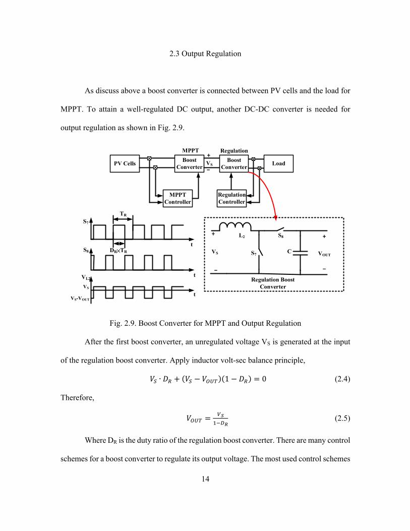
2.3 Output Regulation
As discuss above a boost converter is connected between PV cells and the load for
MPPT. To attain a well-regulated DC output, another DC-DC converter is needed for
output regulation as shown in Fig. 2.9.
PV Cells Boost Converter
MPPT Controller
Boost Converter Load
MPPT Regulation
Regulation Controller
+
-
VS S7
S8
C
L2 +
-
VOUT
Regulation Boost Converter
+
-VS
S7
S8
t
DR╳TR
t
t
VL2
VS-VOUT
VS
TR
Fig. 2.9. Boost Converter for MPPT and Output Regulation
After the first boost converter, an unregulated voltage VS is generated at the input
of the regulation boost converter. Apply inductor volt-sec balance principle,
𝑉N ∙ 𝐷P + 𝑉N − 𝑉QRS 1 − 𝐷P = 0 (2.4)
Therefore,
𝑉QRS =FU
EVWX (2.5)
Where DR is the duty ratio of the regulation boost converter. There are many control
schemes for a boost converter to regulate its output voltage. The most used control schemes

15
are voltage mode control, current mode control.
In voltage control mode, a type III compensator is usually used in boost converters
operating in CCM, and a type II compensator is usually used in boost converters operating
in DCM. Compared to voltage control mode, current control mode has the advantages of
easier compensator design and fast transient response.
Other control schemes such as, hysteresis control and constant-on time control, are
also widely used.
2.4 Prior Work on Multi-Input, Inductor Time-Sharing Boost Converters
1) Using diode between sub-cells and inductor
In [16], multiple PV panels are connected to converter input through diodes and
power switches driven by overlapping control signals. Due to the diodes, during the
overlapping time, only the path from the power source with higher voltage to the converter
would be enabled. This solution eliminates ringing during the dead time, at the input node
when switching between input sources. However, it is not suitable for cell-level (or sub-
cell level) power management due to the large voltage drop across diode.
2) DCM and PCCM operation
Fig. 2.10 shows the inductor current waveform of DCM and PCCM. In DCM,
inductor current goes to zero at the end of every cycle, as shown in Fig. 2.10(a). PCCM
operation is similar to DCM but instead of zero, the current stops decreasing at a pre-
determined positive current level and stays at that current until the next cycle, as shown in
Fig. 2.10 (b). In [14], an energy harvesting system combining power from three different

16
renewable energy sources, including PV cells, is presented. The converter operates in DCM
and achieves peak power-efficiency of 83% at 1 mW input PV power. However, when the
power level is higher, such as a few hundred milli-watts, DCM will bring very high current
ripple, which causes extremely low efficiency, especially when the inductor is being time
shared. In [17], the converter operates in PCCM. PCCM decreases the current ripple
compared to DCM. However, neither DCM nor PCCM operation of the converter provide
good efficiency when the current levels of inputs are widely spread. For MJ-PV cells, the
current and voltage differences of the inputs are large and operating the converter in CCM
(continuous conduction mode) would provide better power efficiency.
Fig. 2.10 Inductor Current Waveform in DCM and PCCM

17
Chapter 3
PROPOSED SINGLE-INDUCTOR DC-DC CONVERTER ENERGY
HARVESTER
3.1 Challenges of Inductor Time-Sharing for MJ-PV Cells
One of the challenges of inductor time-sharing DC-DC converters operating in CCM
for harvesting energy from MJ-PV cells is input cross-regulation. Here, input cross-
regulation describes the change in voltage on one input source caused by the voltage
change on another input source. Conventional DC-DC converter designs assume ideal
power sources that provides a stable output voltage at any current levels. However, this
assumption is no longer valid when the inputs are PV cells. As observed from I-V curve of
PV cells in Fig.1.1, PV output voltage is not constant, but a function of terminal current
and the maximum power is obtained at a particular operating condition.
Inductor time-sharing DC-DC boost converter with two-layer MJ-PV input is shown in
3(a). Inductor L, switches S4 and S5, and load capacitance CL form the boost converter.
Load is represented by RLoad. The converter is connected to sub-cell I and sub-cell II
through switches S1 and S2, respectively. S1 and S2 are ON for D1TIN and D2TIN durations,
respectively in every period TIN, as shown in 3(b). Applying capacitor amp-second balance
principle on C1 and C2, average inductor current (IL) is expressed as,
𝐼< = 𝐼E 𝐷E𝐼< = 𝐼D 𝐷D
(3.1)

18
where, I1, I2 are average current of sub-cell I and sub-cell II, respectively. Assuming
D1 + D2 = 1, I1 is written as,
𝐼E =WH
EVWH𝐼D (3.2)
t
t
t
t
S4
D1×TIN
TIN D2×TIN
(a)
(b)
TC
D×TC
S1
S2
C2
C1 S5VP1
VP2
S1
S2
S4
S5
VOUT
I1
I2
IL
CL RLoad
Fig. 3.1(a) Inductor Time-Sharing DC-DC Converter and (b) Switch Control Signal
As shown in (2), I1 and I2 are correlated, hence sub-cell output voltages (VP1 and VP2)
are correlated as well, and cross-regulation occurs.

19
Assuming converter operates in CCM with switching period of TC. The average input
impedance of the converter is RLoad (1-D) 2. At steady-state condition, boost converter input
impedance is equal to the equivalent output impedance of the MJ-PV cell, and can be
expressed as
𝑅<=>?(1 − 𝐷)D = 𝐷EFGHIH+ (1 − 𝐷E)
FGKIK
(3.3)
As shown in (3.3), the MPPT controller needs to control both D and D1, to achieve
MPP conditions (VP1,MPP, I1,MPP, and VP2,MPP, I2,MPP) for both sub-cells, while conventional
MPPT algorithms for SJ-PV cells controls only converter duty ratio D. Therefore, when
there is input cross regulation, the conventional MPPT algorithms would not work and it
would require complicated algorithms and control circuits to achieve MPPT for an inductor
time-sharing architecture operating in CCM for MJ-PV cells.
This work has focused on reduction of input cross regulation in CCM operation.
Inductor current cannot change instantaneously, and any change in one input current will
be coupled to the inductor current, and then coupled to the other input when switching
among inputs, as shown in (1), (2). In the proposed architecture, a hysteresis current
controller is used to regulate the inductor current, so that it always remains the same
regardless of any change of the inputs. Second, the operating conditions of two inputs are
coupled through D1 and D2, because the S1 and S2 are controlled by complementary signals,
as shown in (2). In this design, an additional power switch S3 is used across the inductor to
decouple D1 and D2. This will be explained in later sections.
20
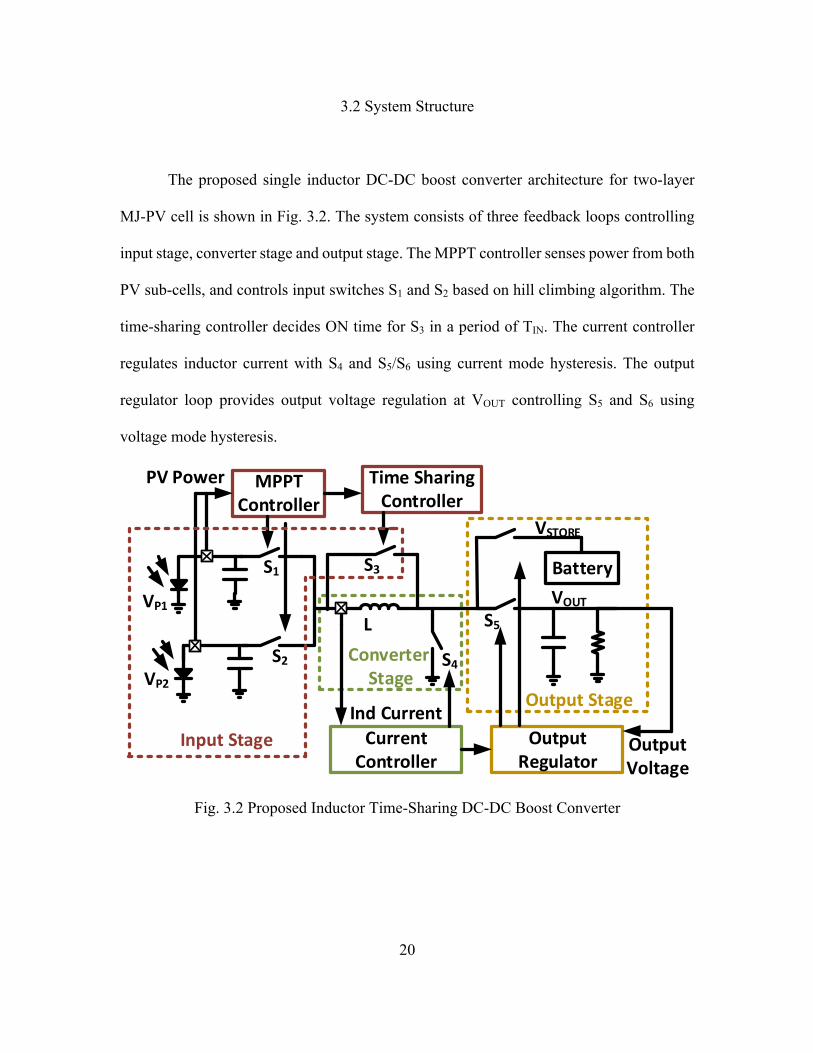
3.2 System Structure
The proposed single inductor DC-DC boost converter architecture for two-layer
MJ-PV cell is shown in Fig. 3.2. The system consists of three feedback loops controlling
input stage, converter stage and output stage. The MPPT controller senses power from both
PV sub-cells, and controls input switches S1 and S2 based on hill climbing algorithm. The
time-sharing controller decides ON time for S3 in a period of TIN. The current controller
regulates inductor current with S4 and S5/S6 using current mode hysteresis. The output
regulator loop provides output voltage regulation at VOUT controlling S5 and S6 using
voltage mode hysteresis.
S1
S2 S4
VOUTVP1
VP2
S3 Battery
InputStage
ConverterStage
OutputStage
MPPTController
CurrentController
OutputRegulator
L
PVPower
IndCurrentOutputVoltage
TimeSharingController
S5
VSTORE
Fig. 3.2 Proposed Inductor Time-Sharing DC-DC Boost Converter

21
3.3 Converter Stage
As discussed above, one of the main causes of cross-regulation in time-sharing
converter is inductor current coupling. Although input cross-regulation can be reduced in
DCM and PCCM operation by always switching from one input source to another when
inductor current is zero or at a constant value, DCM and PCCM causes poor efficiency,
especially in MJ-PV application.
IL
IL
I1+I2
>2I1>2I2
TIN/2 TIN
TIN/2 TIN
t
t
(a)
(b)
∆IL
Fig. 3.3 Time-Sharing Inductor Current (a) in DCM, and (b) in CCM
Fig. 3.3 shows the inductor current of DCM and CCM operation (For simplicity,
assuming D1=D2=0.5). Assuming 2I1 = I2 = 2I, the minimum conduction loss of the

22
converter when operating in DCM is written as,
𝑃<QNN,W\],]^_ =12 2𝐼E D +
4𝐼E D
12 + 2𝐼D D +4𝐼D D
12 (𝑅< + 𝑅Qb)
= c'd𝐼D(𝑅 + 𝑅Qb) ≈ 13.33𝐼D(𝑅 + 𝑅Qb) (3.4)
where, RL and RON are inductor series resistance and switch ON-resistance, respectively.
The conduction loss of converter operating in CCM is expressed as,
𝑃<QNN,\\] = 𝐼E + 𝐼D D + ∆𝐼<D/12 (𝑅< + 𝑅Qb) (3.5)
where, ∆IL is the inductor current ripple. Assuming 100% inductor current ripple (i.e. ∆IL
= I1 +I2), the PLOSS, CCM is written as,
𝑃<QNN,\\] = djc𝐼D(𝑅< + 𝑅Qb) ≈ 9.75𝐼D(𝑅< + 𝑅Qb) (3.6)
Comparing (3.4) and (3.6), the minimal power loss in DCM is much larger than
that in CCM.
In this work, to eliminate cross-regulation in CCM, a current controller, as shown
in Fig. 3.4, is used to regulate the inductor current so that the change in inputs does not
affect the inductor current and therefore reduces the cross-regulation. The controller
consists of an inductor current sensor and a hysteresis comparator, as shown in 6(a). The
sensed inductor current is compared with a maximum value IHigh and a minimum value ILow
using the hysteresis comparator, and the output of the comparator controls low-side switch
S4 of boost converter to regulate IL within the hysteresis window as shown in 3.6(b). The
control signal is also used for output regulation, which will be discussed in 3.6.

23
3.4 Input Stage
A free-wheel switch S3 is added across the inductor as shown in Fig. 3.2 to suppress
cross-regulation caused by complementary control signals (i.e. D1 + D2 = 1) for input
switches S1 and S2.
S4
L
CurrentSensor
+-
IHigh
ILow
OutputRegulator
CurrentController
t
IL
t
IHigh
S4(a)
(b)
ILow
IL
Fig. 3.4 (a) Inductor Current Controller, and (b) Control Signal for S4 and Inductor
Current
The inductor time-sharing in TIN period is shown in Fig. 3.5(a). Switch S1 is ON for
D1TIN duration in every TIN period and the converter harvests energy from MJ-PV sub-cell

24
I as shown in Fig. 3.5(b). As shown in Fig. 3.5(c), the converter harvests energy from MJ-
PV sub-cell II for D2TIN duration in every TIN period when S2 is ON. When S3 is ON, the
inductor freewheels, storing energy in the inductor as shown in Fig. 3.5(d). The inductor
time-sharing controller consists of simple logic gates used to generate S3 from S1 and S2,
so that D1 + D2 + D3 = 1.
3.5 MPPT Controller
Together, the inductor current regulation and inductor time-sharing scheme, reduce
input cross-regulation significantly. Thus, the operating condition of each input PV sub-
cell can be controlled almost independently. Conventional hill climbing algorithms usually
perturb the converter duty ratio to track MPP. In this work, notice from (1) and (2) that
since IL is a regulated constant, I1 is a linear function of D1 and similarly, I2 is a linear
function of D2. Hence, by perturbing D1 and D2, instead of boost duty cycle D, MPPT can
be achieved by directly controlling the PV sub-cell currents. The small variation of
converter operating condition due to the perturbation in D1 or D2 and transferring from one
sub-cell to another, is adjusted by the fast hysteresis inductor-current controller loop, hence
achieving MPPT faster.
The flow chart of hill climbing algorithm is given in Fig. 3.6(a). The algorithm works
based on perturb-and-observe (P&O) principle. Here, duty-ratio (either D1 or D2) is
perturbed and PV sub-cell output power is observed. As shown in Fig. 3.6(b), the MPPT
controller compares the output of PV power monitor with its output from previous cycle.
Based on the comparison, an incremental or decremental signal will be applied to the duty

25
ratio of input switch control signals. If the monitored power is greater than the previous
cycle, then the duty ratio will be perturbed in the same direction as before. Otherwise, it
will be perturbed in the opposite direction. Finally, clock signals are generated by PWM
generators to control the input switches S1 and S2.
S1
S2
VP1
S3
L
I1
I2
PV1 PV2 PV1 PV2
S1
S2
S3
Inductorfreewheel
InductorTime-sharing
D1×TIN
D2×TIN
D3×TIN
TIN
S1
S2
S3
L
I1S1
S2
S3
L
I1
(a) (b)
(c) (d)
VP2
VP1
VP2
VP1
VP2
I2I2
Fig. 3.5 (a) Control Signals for S1, S2 and S3. Converter Current Paths: (b) Sub-cell I, (c)
Sub-cell II, and (d) Free-wheel

26
Start
IncreaseCurrent(IncreaseD1/D2)
MeasurePpv[n]
Ppv[n]>Ppv[n-1]
D1[n]>D1[n-1](D2[n]>D2[n-1])
Yes No
DecreaseCurrent(DecreaseD1/D2)
Yes No
IncreaseCurrent(IncreaseD1/D2)
DecreaseCurrent(IncreaseD1/D2)
YesNo
n=n+1
n=0,I=I0
Current
Power
IncrementD1/D2
DecrementD1/D2
MPP
(a)
D1[n]>D1[n-1](D2[n]>D2[n-1])
S1
S2
PowerMonitor
HillClimbingLogic
TimeSharingController
QD
SAH
MPPTController
+-Power
PWM
PowerComparison
Incremental/Decremental
ClockGeneration
HillClimbingLogic
S1,S2
VP2
VP1
(b)
Fig. 3.6 (a) Hill Climbing Algorithm Flow Chart, and (b) MPPT Controller
Implementation
3.6 Output Regulation
As shown in Fig. 3.7, the output stage has two paths: one primary path and one
secondary path.

27
VOUT
t
t
t
t
S6
S5
S4
S5
S6Battery
+
-
S4
VOUT
OutputStage
CurrentController
VHVL
VH
VL
PrimaryPath
SecondaryPath
(a) (b)
VSTORE
Fig. 3.7 (a) Output Voltage Regulation Loop, and (b) VOUT and Control Signals for S4, S5
and S6.
A hysteresis comparator monitors the output voltage, compares it to the two
references VH and VL and enables either primary path or secondary path:
(1) When output is lower than VL, the primary path will be enabled. S5 turns on whenever
S4 is off and S6 will be disabled. The input power will be delivered to the load.
(2) When output is higher than VH, the secondary path will be enabled. S6 turns on
whenever S4 is off and S5 will be disabled, the power will be delivered to and stored in the
battery.
Therefore, the hysteresis control loop provides regulated output voltage by storing
extra input energy that load doesn’t require, to battery storage.

28
Chapter 4
CIRCUIT DETAILS
4.1 Inductor Current Sensor
Inductor current sensing is necessary for any DC-DC converter controlled in current
mode. A series resistor (for current sensing) causes significant power loss. Mirroring
current from power switches to sense the inductor current is a common technique used to
avoid series resistors. As shown in Fig. 3.5, inductor is time shared between S1, S2 and S3.
Therefore, the inductor current can be sensed from power switches S1, S2 and S3. Fig. 4.1(a)
shows the current sensing circuit of S1. Two identical mirror switches SM1 and M1 are
connected in series and then in parallel with S1. The ratio between mirror switches and
power switch S1 is 1:640. A common gate amplifier provides a small bias current IB at its
inputs. The feedback loop ensures the same voltage at the node VA and VB. M1 and M2 are
identical and both operates in linear region. Therefore,
𝐼]E = 𝐼]D (4.1)
𝐼]j = 𝐼]D − 𝐼n = 𝐼]E − 𝐼n = 𝐼]_NE (4.2)
Similarly, current through S2 and S3 can be sensed in the same way. Since S1, S2 and
S3 are complementary. The mirror switch M1 and the op-amp can also be time-shared.
Fig. 4.1(b) shows the complete implementation of the current sensor. The mirrored
current of three switches sums up at node VA. The sensed inductor current through M9 is
written as,
𝐼] = EEDp'
𝐼< (4.3)

29
The ratio between M9 and M10 is K2:1. M11 and M12 has the same size. Therefore, the
sensor output voltage VS is expressed as,
𝑉N = 𝑉WW −E
DqHqK𝐼<𝑅 (4.4)
In the design, values of K1 and K2 are 640 and 4, respectively.
A cross-coupled common-gate amplifier is used as A0. Transistors M3-M8, and current
sources IB2 form A0 amplifier. Input cross-coupled pair (M4-M5) provides fast transient
response required for inductor hysteresis current loop.
SM1
SM2
VP1
VP2
VP VSW
SM2SM1 SM3
VP1 VP2 VSW
VP
VDDMirrorswitches
VA
VS
IM
VDD
IM1 IM2
IB1
IM9
IOUT
M1 M2
M3 M4
R
S1
SM1
S2
S3VP1
VP2
VP
VSW
SM1
VP1
VA
VDD
VB
VDD
IM1 IM2
M1 M2
M9
VB1
IB1
S1
S2
S3
SM3
VB2
VDD
M5 M6
M7 M8
M9 M10
VB
VA
VA
VA
S1 S1
M1
CurrentSensor
PowerStage
PowerStage
CurrentSensor
IM9
(a)
(b)
IB IB
IM_S1
VP
M12M11
IB2 IB2
A0
Fig. 4.1 (a) Current Sensor for S1, and (b) Inductor Current Senso

30
4.2 Power Monitor
As discussed before, for MPPT, PV power monitoring is necessary. Traditional
analog power monitors usually employ power-hungry current sensors on power paths. A
time-based power monitor is designed as shown in 11, and the basic concept is taken from
[18].
VP1(VP2)
R
C
M1
M2 M3
M4
M5
VC1(VC2)
Pulseamplitudemodulator PulseIntegrator
(S2)S1
RESET
A1
VDD VDD VDD
Fig. 4.2 Power Monitor Circuit
The power monitor consists of a pulse amplitude modulator (PAM), a pulse
integrator (PI), and a switch M4. The PAM is formed by an op-amp, a resistor R, and
transistors M1-M3. The PAM converter the PV voltage information into current. The PI
consists of a capacitor C. The ON time of M4 controls the integration time. The duty-ratio
(D1, D2) of S1 and S2 control signals carry information of current (I1, I2) through S1 and S2
switches. Thus, the PI calculates instantaneous PV power represented by voltage VC across

31
C. Switch M5 connected across C resets the power monitor at the beginning of every MPPT
cycle.
Using (3.1), the outputs (VC1 and VC2) of the power monitors used for sub-cell I
and sub-cell II are expressed as,
𝑉\E =
FGHWHSrsP\
= FGHIHSrsP\It
∝ 𝑉vE𝐼E
𝑉\D =FGKWKSrs
P\= FGKIKSrs
P\It∝ 𝑉vD𝐼D
(4.5)
4.3 Sample and Hold Block
In any hill climbing or P&O algorithm implementation, sample and hold block is
essential to store the PV power information from the previous cycle. When the PV
operating point is close to its MPP, the power difference ∆P become smaller and smaller.
Therefore, the accuracy of the sample and hold block is crucial. If the accuracy is poor, the
oscillation around the MPP will be larger and causes the MPPT efficiency to decrease.
Since each MPPT cycle is typically from a few hundred micro-seconds to a few milli-
second, the sample and hold block need to hold the power information for a long time.
Fig. 4.3 shows the implemented sample and hold circuit. Two transmission gate T1
and T2 between input and output reduces leakage. The transmission gate T3 turns on during
the hold time and the op-amp in unity gain feedback ensures that the voltage across T2 is
the zero and therefore further decreases the leakage. This sample and hold topology is able
to hold the PV power information for seconds.

32
T1 T2
T3
VOUTVIN
CLK CLK
CLKCLKNOT
CLKNOT CLKNOT
Fig. 4.3 Sample and Hold Circuit

33
Chapter 5
EXPERIMENTAL RESULTS
The proposed system was implemented in standard 0.18-um CMOS process. The
die microphotograph is shown in Fig. 5.1. The power switches and control circuits occupies
silicon area of 1.5mm×3mm.
Fig. 5.1 Die Microphotograph
5.1 Test Board and Measurement Setup
A test board is designed for the measurement of this IC as shown in Fig. 5.2. Two
different PV cells are used as input sources to mimic the sub-cells of a MJ-PV. A 1F super-
capacitor is used as power storage on the secondary path at VSTORE. An 8.2uH inductor is

34
used. A 10uF input capacitor was placed at each PV cells. At full light intensity, the two
PV cells generates around 8mW and 59mW of power, respectively.
Fig. 5.2 Test Board
5.2 Top-level Measurement Results
Fig. 5.3 shows the measurement result of inductor time-sharing. The input switches
S1, S2 and the free-wheeling switch S3 operates at approximately 100 KHz. As shown in
Fig. 5.3, the inductor is being time-shared by these three switches. During S1, the PV sub-
cell I is enabled and the converter input node VP follows sub-cell I output voltage VP1.
During S2, the PV sub-cell II is enabled and the converter input node VP follows sub-cell

35
II output voltage VP2. During S3, inductor free-wheels and the converter input node is set
to zero. This is because switch S3 is implemented by a NMOS transistor, setting VP to zero
minimizes the ON-resistance of the switch.
PV1OutputVoltageVP1
PV2OutputVoltageVP2
InputNodeVoltageVP
Fig. 5.3 Inductor Time-Sharing
The output of the primary path (i.e. external load) is regulated at 1.8V and the output
of secondary path (i.e. super-capacitor) is set at around 2V.
Fig. 5.4 shows the measured efficiencies. For efficiency measurements, VSTORE is
set to 1.8V. The total output power is measured as the sum of the power to VLOAD and
VSTORE. The converter achieves peak efficiency of around 85% at full load.
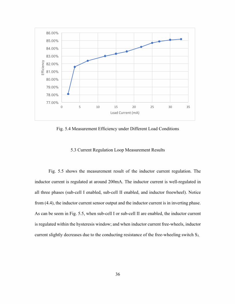
36
Fig. 5.4 Measurement Efficiency under Different Load Conditions
5.3 Current Regulation Loop Measurement Results
Fig. 5.5 shows the measurement result of the inductor current regulation. The
inductor current is regulated at around 200mA. The inductor current is well-regulated in
all three phases (sub-cell I enabled, sub-cell II enabled, and inductor freewheel). Notice
from (4.4), the inductor current sensor output and the inductor current is in inverting phase.
As can be seem in Fig. 5.5, when sub-cell I or sub-cell II are enabled, the inductor current
is regulated within the hysteresis window; and when inductor current free-wheels, inductor
current slightly decreases due to the conducting resistance of the free-wheeling switch S3.
77.00%
78.00%
79.00%
80.00%
81.00%
82.00%
83.00%
84.00%
85.00%
86.00%
0 5 10 15 20 25 30 35
Efficiency
LoadCurrent(mA)

37
Fig. 5.5 Converter Stage Measurement Results
5.4 MPPT Transient
The duty ratio of the input clocks are measured at different light intensity to verify
the functionality of MPPT as shown in Fig. 5.6. The MPPT functionality can be
characterized as the relationship between light intensity and duty ratio of input clocks.
When light intensity is low, as shown in Fig. 5.6 (a), MPP current is low so that the duty
ratio of input clocks are low; while when light intensity is high, as shown in Fig .5.6(b),
the MPP current is high, so that the duty ratio of the input clocks are high. A transient
measurements were also carried to verify the MPPT dynamic performance. As shown in
Fig. 5.7, initially, the light intensity is low and the two PV outputs are 0.9V and 0.3V,
respectively. Then the light intensity increases, and PV output voltage increases but reaches
back to MPP voltage due to the MPPT control loop.

38
(a) Input Clock at Low Light Intensity
(b) Input Clock at High Light Intensity
Fig. 5.6 Input Clock Signals at Different Light Intensity

39
Fig. 5.7 MPPT Transient

40
Chapter 6
CONCLUSION AND FUTURE WORK
This thesis proposes a low cost, single-inductor, dual-input, CCM boost converter
with MPPT for MJ-PV energy harvesting system. The input PV cells provide a few hundred
milli-watt of power. CCM operation provides better efficiency than in DCM or PCCM.
Inductor time-sharing provides a cost-effective solution for combining power from MJ-PV
sub-cells. An inductor current regulation loop keep inductor current constant in both input
condition and therefore reduces cross-regulation in CCM. A current-mirror based current
sensor is used to sense instantaneous inductor current without causing any significant
power loss. A modified hill climbing algorithm achieves MPPT for both sub-cells. A time-
based power monitor senses PV power and the algorithm is based on PV current
perturbation, which provides fast MPPT transient response. A dual-path output architecture
provides a regulated output voltage of 2V. The boost converter works at around 1MHz and
the input stages operates at around 100KHZ. The measured peak efficiency is around 85%.
Table 1 shows a comparison of the proposed system with previously published
designs. Generally, DC-DC converters in DCM achieves higher efficiency at low input
power, while that in CCM has better performance at higher input power. As can be seen,
the proposed system processing higher PV power in CCM achieves higher peak efficiency
than the inductor-sharing design processing lower PV input power in DCM. Although the
peak efficiency of the proposed system is two percent lower than that of state-of-the-art
single input boost converter, it has an advantage of less component count and much lower
cost.

41
The future work includes the following:
1) Increase the number of inputs. This can be easily done with the same topology.
2) Recycling stored power in the secondary path using a buck converter. The buck
converter delivers power from the storage unit (such as, battery or super capacitor) to one
of the input of the multi-input boost converter.
3) To further increase the power efficiency, the inductor free-wheeling time must be
minimized. An adaptive inductor current hysteresis window can be designed to
dynamically minimize the inductor free-wheeling time.
Parameter JSSC 2012 [14] APEC 2011 [17] ISSCC 2011 [19] This Work
Energy Source
Photovoltaic,
Thermoelectric and
Vibration
PV panels Single PV cell MJ-PV Cell
Number of Inputs 3 multiple 1 2
Number of Inductors 1 1 1 1
Converter Operating Mode DCM PCCM DCM CCM
Maximum PV Output
Power 2.5mW 170W 1.66mW 65mW
Peak Efficiency of power
converters 83% NA 87% 85%
Table 1. Comparison Table

42
REFERENCES
[1] C.H. Henry, “Limiting efficiencies of ideal single and multiple energy gap terrestrial solar cells”, J. Appl. Phys., 51(8), 1980 [2] R. R. King, A. Boca, W. Hong, D. Law, G. Kinsey, C. Fetzer, M. Haddad, K. Edmondson, H. Yoon, P. Pien, and N. Karem, “High-efficiency multi-junction photovoltaics for low-cost solar electricity,” in Proc. Ann. Meeting IEEE Lasers and Electro-Optics Society, Nov. 2008, pp. 2–3. [3] R. R. King et al., “Solar cell generations over 40% efficiency,” Prog. Photovolt.: Res. Appl., vol. 20, pp. 801–815, 2012, doi: 10.1002/pip.1255. [4] M. A. Green and A. Ho-Baillie, “Forty three per cent composite split-spectrum concentrator solar cell efficiency,” Prog. Photovoltaics: Res. Applicat., vol. 18, pp. 42–47, 2010. [5] F. Dimroth, T. N. D. Tibbits, P. Beutel, C. Karcher, E. Oliva, G. Siefer, M. Schachtner, A. Wekkeli, M. Steiner, M. Wiesenfarth, A. W. Bett, R. Krause, E. Gerster, M. Piccin, N. Blanc, M. Muñoz Rico, C. Drazek, E. Guiot, J. Wasselin, C. Arena, T. Salvetat, A. Tauzin, T. Signamarcheix, T. Hannappel, “Development of high efficiency wafer bonded 4- junction solar cells for concentrator photovoltaic applications”, 40th IEEE Photovoltaic Specialist Conference, Denver, CO, 2014, pp. 840-843. [6] B. R. Conley, H. Naseem, G. Sun, P. Sharps, and S.- Q. Yu, "High efficiency MJ solar cells and TPV using SiGeSn materials," in Photovoltaic Specialists Conference (PVSC), 2012 38th IEEE, 2012, pp. 001189-001192. [7] T. Esram and P. L. Chapman, “Comparison of photovoltaic array maximum power point tracking techniques,” IEEE Trans. Energy Convers., vol. 22, no. 2, pp. 439–449, Jun. 2007. [8] W. Xiao and W. G. Dunford, “A modified adaptive hill climbing MPPT method for photovoltaic power systems,” in Proc. 35th Annu. IEEE Power Electron. Spec. Conf., 2004, pp. 1957–1963. [9]F. A. O. Aashoor and F. V. P. Robinson, “A Variable Step Size Perturb and Observe Algorithm for Photovoltaic Maximum Power Point Tracking,” Universities Power Engineering Conference (UPEC), 2012 47th International, pp. 1 - 6, 4 - 7 September 2012. [10] B. N. Alajmi, K. H. Ahmed, S. J. Finney, and B. W. Williams, “Fuzzy logic-control approach of a modified hill-climbing method for maximum power point in microgrid standalone photovoltaic system,” IEEE Trans. Power Electron., vol. 26, no. 4, pp. 1022–1030, Apr. 2011.

43
[11] O. Wasynczuk, “Dynamic behavior of a class of photovoltaic power systems,” IEEE Trans. Power App. Syst., vol. 102, no. 9, pp. 3031–3037, Sep. 1983. [12] H. Guan-Chyun, I. H. Hung, T. Cheng-Yuan, and W. Chi-Hao, “Photovoltaic power-increment-aided incremental-conductance MPPT with two-phased tracking,” IEEE Trans. Power Electron., vol. 28, no. 6, pp. 2895–2911, Jun. 2013. [13] P. Midya, P. T. Krein, R. J. Turnbull, R. Reppa, and J. Kimball, “Dynamic maximum power point tracker for photovoltaic applications,” in Proc. 27th Annu. IEEE Power Electron. Spec. Conf., 1996, pp. 1710–1716. [14] S. Bandyopadhyay, A.P. Chandrakasan, "Platform architecture for solar, thermal and vibration energy combining with MPPT and single inductor," IEEE Journal of Solid-State Circuits,, vol. 47, no. 9, pp. 238-239, June 2012. [15] M. Alam, F. Khan, and A. Imtiaz, “Optimization of sub-cell interconnection for multi-junction solar cells using switching power converters,” IEEE Trans. Sustain. Energy, vol. 4, no. 2, pp. 340–349, Apr. 2013. [16] J. Abu Qahouq and Y. Jiang, "Distributed photovoltaic solar system architecture with single-power inductor single-power converter and single-sensor single maximum power point tracking controller," IET Power Electronics, vol. 7, no. 10, pp. 2600-2609, Oct. 2014. [17] S. Poshtkouhi and O. Trescases, “Multi-input single-inductor dc–dc converter for MPPT in parallel-connected photovoltaic applications,” in Proc. 26th Annu. IEEE Appl. Power Electron. Conf. Expo., 2011, pp. 41–47 [18] S. Uprety and H. Lee, “A 43V 400mW-to-21W global-search-based photovoltaic energy harvester with 350 µs transient time, 99.9 % MPPT efficiency, and 94 % power efficiency,” in Dig. Tech. Papers IEEE Int. Solid-State Circuits Conf. (ISSCC), 2014, pp. 404–405. [19] Y. Qiu, C.V. Liempd, B.O. Veld, P.G. Blanken, and C.V. Hoof, "5ȝW-to- 10mW Input Power Range Inductive Boost Converter for Indoor Photovoltaic Energy Harvesting with Integrated Maximum Power Point Tracking Algorithm," in Proc. IEEE International Solid-State Circuits Conference Digest of Technical Papers, pp. 118-119, Feb. 2011.


![Modeling and Control of a Multi-stage Interleaved …by Cuk in buck-boost converter [6], [7]. In [8], Witulski has shown how a coupled inductor´ differs from normal inductor and transformer](https://img.pdfslide.us/doc/110x75/5f4d972268593756d475e471/modeling-and-control-of-a-multi-stage-interleaved-by-cuk-in-buck-boost-converter.jpg)


![Research on Power Factor Correction Boost Inductor Design …1].pdf · Two Boost Pseudo Totem‐pole Totem‐pole Fig. 2. Efficiency comparison only for conduction losses among six](https://img.pdfslide.us/doc/110x75/609835766c522e2df02c7c17/research-on-power-factor-correction-boost-inductor-design-1pdf-two-boost-pseudo.jpg)


![Enhanced-Boost Quasi-Z-Source Inverters with Two Switched … · 2017-09-26 · switched inductor (SL) cells and are proposed in [7] and [8] Enhanced-Boost Quasi-Z-Source Inverters](https://img.pdfslide.us/doc/110x75/5f0a34397e708231d42a83cb/enhanced-boost-quasi-z-source-inverters-with-two-switched-2017-09-26-switched.jpg)