Embed Size (px)
Citation preview

NXESI120 External Servo Interface
For NX6100 and PPC6000 Series
DESCRIPTION
The NXESI120 interface provides the facility to connect non-CANbus servo motors, for example NX20, NX50, NX98 or third party devices, into a NEXUS control system. The NXESI120 has connections to the CANbus and to the servo motor. The CANbus powers and communicates with the on-board microprocessor and associated CANbus circuitry. Connections to the motor are at Line supply levels (typically 120 or 230Vac) and 5Vdc levels to the feedback potentiometer.
CAN modules used in the NEXUS family, have unique serial numbers programmed during manufacture. These serial numbers are used to define the device type and its function as part of the combustion control system, during commissioning. CAN servo motors and the NXESI120 are considered to be ‘Drives’. Note: If a drive serial number is changed after commissioning, then any profiles using that drive will require re-commissioning. A ‘profile invalid’ fault (see FAULT 64) will lock the burner out on an attempt to fire a profile which has had a previously commissioned drive removed or changed. The profile can be re-commissioned by using the NEXT / ENTER ‘keys’ in commission ratio mode to verify all points on the combustion curve.
NXESI-6101 June 19, 2015

2
Safety information
WARNING
When this equipment is fitted to an appliance due regard must also be given to the requirements of that appliance. Before attempting to install, commission or operate this equipment all relevant sections of this document must be read and fully understood. If in doubt about any requirements consult Fireye. Installation, commissioning or adjustment of this product MUST be carried out by suitably trained engineers or personnel qualified by training and experience. After installation or modifications to the installation all functions of the equipment MUST be checked to ensure safe and reliable operation of the control. The manufacturer of this equipment accepts no liability for any consequences resulting from inappropriate, negligent or incorrect installation, commissioning or adjustment of operating parameters of the equipment. Control panels must not be left uncovered while power is on. If it is essential to do so while rectifying faults only personnel qualified by training and experience should be involved. The time any covers are off must be kept to a minimum and warning notices must be posted. Before attempting any work on this equipment or any equipment controlled by or connected to this equipment, all related electrical supplies must be isolated. Safety interlocks must not be removed or over-ridden. Any faults once detected must be corrected before the control is operated. CAUTION – SOME VERSIONS OF THIS EQUIPMENT CONTAIN A LITHIUM BATTERY
IN THE DISPLAY UNIT
NOTE The manufacturer of this equipment has a policy of continual product improvement and reserves the right to change the specification of the equipment and the contents of this manual without notice.
The equipment described in this manual is capable of causing property damage, severe injury, or death. It is the responsibility of the owner or user to ensure that the equipment described herein is installed, operated and commissioned in compliance with the requirements of all national and local legislation, which may prevail.

3
Table of contents
This manual describes the configuration of the NXESI120 External Servo Motor Interface. Please read the safety information at the front of this manual before proceeding.
1. Installation 4 1.1 Overview. 4
2. Installation 5 2.1 Mechanical Fixing 5 2.2 Option Link selection 5 2.3 Wiring Information 6
3. Servo motor selection and calibration. 10 3.1 Servo-motor selection 10 3.2 Locking the servo-motor to the valve shaft 11 3.3 Control direction 11 3.4 Feedback potentiometer 11 3.5 Adjusting micro-switch positions when using Fireye line voltage servomotors. 12
4. Technical Specification. 13 4.1 General 13

4
1. Installation
1.1 Overview. The NXESI120 interface provides the facility to connect non-CANbus servo motors, for example NX20, NX50, NX98 or third party devices, into a NEXUS control system. The NXESI120 has connections to the CANbus and to the servo motor. The CANbus powers and communicates with the on-board microprocessor and associated CANbus circuitry. Connections to the motor are at Line supply levels (typically 120 or 230Vac) and 5Vdc levels to the feedback potentiometer. CAN modules used in the NEXUS family, have unique serial numbers programmed during manufacture. These serial numbers are used to define the device type and its function as part of the combustion control system, during commissioning. CAN servo motors and the NXESI120 are considered to be ‘Drives’. Note: If a drive serial number is changed after commissioning, then any profiles using that drive will require re-commissioning. A ‘profile invalid’ fault (see FAULT 64) will lock the burner out on an attempt to fire a profile which has had a previously commissioned drive removed or changed. The profile can be re-commissioned by using the NEXT / ENTER ‘keys’ in commission ratio mode to verify all points on the combustion curve.

5
2. Installation
2.1 Mechanical Fixing The NXESI120 interface has an IP65 enclosure with 3 cable entry points. Suitable IP65 conduit connections should be used to ensure continuity of the IP rating as required. Mechanical fixing is using the 4 points outside of the IP65 area as shown below:
2.2 Option Link selection There are two option links that must be set according to the potentiometer configuration within the servo motor, as follows. Direct (1:1) potentiometer drive, or Geared (3:1) potentiometer drive.
100
160
145
63
Mounting holes 4 x 4.5mm dia.
mm (6.3”)
mm (3.93”)
mm (5.71”)
63 mm (2.48”)

6
JP3 JP2
DIRECT DRIVE
DIRECT DRIVE
JP3 JP2
GEARED DRIVE
GEARED DRIVE
2.3 Wiring Information
2.3.0 General
CAUTION
The enclosure MUST be earthed to ensure safe and reliable operation. The screen terminals on the NXESI120 only perform an ground function and do not provide strain relief, the signal cable screens only connect at the screen terminals, unless stated otherwise. Secure all cables carried in conduit at both ends using a suitable anchorage method in the cabinet. WIRING INSTALLATION MUST BE CARRIED OUT BY A COMPETENT ELECTRICIAN AND IS SUBJECT TO I.E.E. WIRING REGULATIONS (BS 7671:1992) AND/OR LOCAL STANDARDS WHICH MAY PREVAIL. HAZARDOUS VOLTAGES MUST BE ISOLATED BEFORE SERVICE WORK IS CARRIED OUT. All cabling requiring to operate at above 50v must be multi-strand single core PVC insulated 16/0.2mm and should meet the requirements of I.E.C. 227 or I.E.C. 225. Do not use a green/yellow conductor for any purpose other than earth. To comply with EMC requirements, wire the NXESI120 expansion unit using the specified cable sizes and screen connections. Clamp all signal cable screens to earth using the screen terminals provided on the NXESI120. Connect all CANBus cable screens to earth at the control end using the screen termination clamps only.
Disconnect the power supply before beginning installation to prevent electrical shock, equipment and/or control damage. More than one power supply disconnect may be involved.
Wiring must comply with all applicable codes, ordinances and regulations. Loads connected to the NXESI120 unit must not exceed those listed in the specifications as given in
this manual.
JP3 JP3JP2 JP2

7
The equipment described in this manual has been tested for compliance to the directives listed in the section headed ‘approvals’ in the NEXUS manual NEX-6101. However, once connected to a burner and other associated controls it is the responsibility of the installer to ensure the complete installation meets
the requirements of the directives relevant to the particular installation.
2.3.1 Terminal layout.
Connection terminals are identified in the picture below.
2.3.2 Grounding CANBus cable screens.
Several screen termination clamps are provided on the main control. The cable should be prepared by cutting around the outer sleeve, taking care not to damage the screen
(1). Cut the outer insulation to expose the screen. (2). Pull the sleeving apart to expose 10mm of the screen, (3). Slide the exposed length of screen between the conductive strip in the clamp.
10mm
(1)
(2)
J4
J1 J3
J5

8
Terminals 5 and 6 on J3 are the termination points for CANBus screens in the NXESI120.
2.3.3 EARTH connection.
Make an Earth connection to the NXESI120 at the Earth connection point J5. Ensure that a good electrical connection is made both between the NXESI120 and the servo motor to be controlled at this point. Where necessary, scrape any paint away from connection points and use shake-proof washers to obtain a reliable electrical connection. Always use the largest cross-sectional area earth wire possible.
2.3.4 Line supply and servo motor connections.
The LIVE and NEUTRAL supplies must be connected using multi-strand single core PVC insulated 16/0.2mm wire. The ‘Live In’ connection should be fused with a maximum rating as specified for the servo motor. The motor up/down outputs should be connected using multi-strand single core PVC insulated 16/0.2mm wire. The connections to the motor should be made via its switched inputs, so that the internal micro-switches prevent the motor/linkage being damaged if it is driven to either end of its travel. Motor feedback potentiometer cabling must be overall mesh screened, 3-core, PVC insulated 7/0.2mm. Since this cable may be run in conduit with the motor drive wiring, its voltage rating must exceed the maximum voltage carried by any other cable in the same conduit.
Connect the motor feedback potentiometer cable screen to terminal J1-4. Make all connections at the servo-motor first. Incorrect connection may damage or destroy the motor potentiometer.
5k linear
MClose J4-5
Open J4-4
Neutral J4-3
115 - 230Vac
0Vdc J1-1
5Vdc J1-3
Wiper J1-2
Screen J1-4
Neutral In J4-2
Line In J4-1

9
2.3.5 CANBus connection
CAUTION
There are 2 sets of terminals on the controller available for the CANbus connection, PA and PB1-4. Terminals J3-1 to J3-4 are the corresponding connections on the NXESI120.
CANbus allows several options for connecting the devices together, based on the physical position of each device relative to the main controller and the current required by each device. Once the location of each device is defined (usually by the mechanical construction of the burner and boiler) the most suitable cable route to each device can
be selected. If required, several cables can be run directly from the main controller or a single cable can be ‘looped through’ all the connected devices, providing the maximum current capability of the cable is not exceeded. Consult the controller manual for CANbus wiring specifications. Ground the screens cables as detailed in section 2.3.2. If wiring is being ‘looped through’ devices, ensure that the screens of the cables are connected to the terminals J3-5 and J3-6 to ensure continuity of the screen.
Controller
24Vac PA 1 / PB 1
24Vac PA 2 / PB 2
CANbus + PA 3 / PB 3
CANbus – PA 4 / PB 4
NXESI120 24Vac J3-1 24Vac J3-2 CANhi (+) J3-3 CANlo (–) J3-4
The total electrical load for the CANbus when connected to a single controller MUST NOT exceed 40VA.
Incorrect connection may damage or destroy the units being connected.

10
3. Servo motor selection and calibration.
WARNING
3.1 Servo-motor selection
3.1.0 Motor requirements
Servo-motors supplied by Fireye meet the following guidelines for suitability: Servo-motors must be in the operating voltage range of 24Vac to 250Vac rms.
Servo motors must be ac powered.
The servo-motor current must not exceed 1A ac rms.
The motor supply to the NXESI120 interface must be protected with a suitable fuse for the motors being used.
The servo-motor run-time for 90° movement must not be less than 25 seconds or more than 35 seconds.
All servo-motors must have internal limit switches which must be adjusted during commissioning to prevent excessive rotation.
All servo-motors must be able to drive the load imposed on them.
All servo-motors must have suitable protection for the burner environment (for example, IP65 for applications exposed to the weather).
If in any doubt about a particular servo-motor’s suitability, seek confirmation from your equipment supplier.
3.1.1 Potentiometer requirements
All servo-motor potentiometers should be good quality plastic film types, with high resolution. A minimum resistance of 1kΩ is allowed for the feedback potentiometers to prevent excessive current consumption. Up to a 5K value may be used for third party devices. The potentiometer must be securely fixed to the output shaft of the gearbox in such a way as to give accurate indication of the shaft position under all conditions and at all times. Where a grub screw system is used to secure the potentiometer to the servo-motor shaft, ensure it is tightened to prevent any movement of the servo-motor shaft in relation to the potentiometer.
Valve and motor alignment, and calibration must be set in Commission Ratio mode prior to commissioning any profile set-points
11
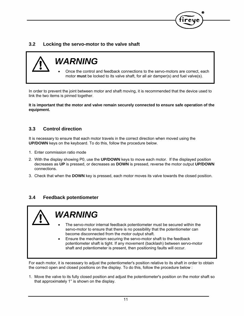
3.2 Locking the servo-motor to the valve shaft
WARNING
In order to prevent the joint between motor and shaft moving, it is recommended that the device used to link the two items is pinned together. It is important that the motor and valve remain securely connected to ensure safe operation of the equipment.
3.3 Control direction It is necessary to ensure that each motor travels in the correct direction when moved using the UP/DOWN keys on the keyboard. To do this, follow the procedure below. 1. Enter commission ratio mode
2. With the display showing P0, use the UP/DOWN keys to move each motor. If the displayed position decreases as UP is pressed, or decreases as DOWN is pressed, reverse the motor output UP/DOWN connections.
3. Check that when the DOWN key is pressed, each motor moves its valve towards the closed position.
3.4 Feedback potentiometer
WARNING
For each motor, it is necessary to adjust the potentiometer's position relative to its shaft in order to obtain the correct open and closed positions on the display. To do this, follow the procedure below : 1. Move the valve to its fully closed position and adjust the potentiometer's position on the motor shaft so
that approximately 1° is shown on the display.
The servo-motor internal feedback potentiometer must be secured within the servo-motor to ensure that there is no possibility that the potentiometer can become disconnected from the motor output shaft.
Ensure the mechanism securing the servo-motor shaft to the feedback potentiometer shaft is tight. If any movement (backlash) between servo-motor shaft and potentiometer is present, then positioning faults will occur.
Once the control and feedback connections to the servo-motors are correct, each motor must be locked to its valve shaft, for all air damper(s) and fuel valve(s).

12
2. Move the valve to its fully open position and check that the display reads approximately 90° or the maximum angular opening required from the servo-motor if this is less than 90°. If the displayed position decreases as the valve is opened, reverse the supply connections to the feedback potentiometer. If the displayed position range is incorrect, check that the correct potentiometer supply voltage has been selected.
3.5 Adjusting micro-switch positions when using Fireye line voltage servomotors. Each time a burner start-up sequence is initiated, the control will move the fuel and air damper motors to their closed and purge positions to prove correct motor and potentiometer operation. Each motor must have micro-switches fitted to limit the closed and fully open positions obtainable during this proving operation. To set the micro-switch positions, follow the procedure below. 1. Enter the commission ratio mode of the controller and scroll the display to show the feedback value for
the servo-motor.
2. Move the motor to approximately 45°, either by hand or using the UP/DOWN keys.
3. Holding the DOWN key, tighten up the low limit micro-switch until the motor will no longer move down.
4. Holding the DOWN key, gradually slacken off the low limit micro-switch until the motor starts moving down. Continue to slacken off the micro-switch until the motor stops with a reading on the display of approximately 2°.
5. Move the motor up and down a few times to check that the motor stops each time at approximately 2°, and re-adjust the micro-switch if necessary. This position will allow for some tolerance in micro-switch operation.
6. Hold the UP key and tighten up the high limit micros-witch until the motor will no longer move up.
7. Holding the UP key, gradually slacken off the high limit micro-switch until the motor starts moving up. Continue to slacken off the micro-switch until the motor stops in the desired fully open position. This position does not have to be 90°, but it is recommended that it is more than 85°.
8. Move the motor, up and down a few times to check that the motor stops each time at the desired fully open position. Repeat steps 3 to 7 if necessary.

13
4. Technical Specification.
4.1 General
Interface Supply Ambient operating range Interface protection category Interface dimensions Mounting Attitude Weight Cable Lengths Motor Supply Voltage Motor Supply Current Supply frequency Motor speed Motor feedback Potentiometer
CANBus 24Vac 0 to 60°C IP65 (Nema 4X) 160 x 100 x 63mm (6.3x3.93x2.48) Any 0.75kg CANBus cable 100m, all others 10m maximum 24/120/230Vac +10% - 15% 1A ac rms Maximum
50/60 Hz 5% 25 – 35s /90° 1kΩ – 10kΩ ± 10%, Linearity 10%

14
NOTICE
When Fireye products are combined with equipment manufactured by other and/or integrated into systems designed or manufactured by others, the Fireye warranty, as stated in its General Terms and Conditions of Sale, pertains only to the Fireye products and not to any other equipment or to the combined system or its overall performance.
WARRANTIES
FIREYE guarantees for one year from the date of installation or 18 months from date of manufacture of its products to replace, or, at its option, to repair any product or part thereof (except lamps and photocells) which is found defective in material or workmanship or which otherwise fails to conform to the description of the product on the face of its sales order. THE FOREGOING IS IN LIEU OF ALL OTHER WARRANTIES AND FIREYE MAKES NO WARRANTY OF MERCHANTABILITY OR ANY OTHER WARRANTY, EXPRESS OR IMPLIED. Except as specifically stated in these general terms and conditions of sale, remedies with respect to any product or part number manufactured or sold by Fireye shall be limited exclusively to the right to replacement or repair as above provided. In no event shall Fireye be liable for consequential or special damages of any nature that may arise in connection with such product or part.
NXESI-6101 June 19, 2015
FIREYE 3 Manchester Road Derry, New Hampshire 03038 USA www.fireye.com