Embed Size (px)
Citation preview
8/2/2019 nv23
http://slidepdf.com/reader/full/nv23 1/14
Column #23: Electronic Control for DC Motors Using Discrete Bridge Circuits
The Nuts and Volts of BASIC Stamps (Volume 1) •••• Page 229
Column #23, January 1997 by Scott Edwards:
Electronic Control for DC MotorsUsing Discrete Bridge CircuitsGallery of motor-control circuits and motor-control basics
MOTORS FASCINATE Stamp users. They seem to be looking for a mythical universalmotor-controller that interfaces to Stamps, controls any motor from 0.1 to 100 amps at 1to 50 volts, is 100% efficient, and costs less than $5.
We keep those on a shelf in the back, between the perpetual-motion machines and thereplacement teleporter pattern buffers. This month, we’ll look at several types of
practical motor-control circuits suitable for use with the Stamps.
DC Motor ABCs
Before we look at our gallery of circuits, let’s agree on a couple of terms:
• In this article, motor means a permanent-magnet, direct-current (DC) motor of the sort used in toys, models, cordless tools, and robots. These motors are
particularly versatile because both their speed and direction can be readilycontrolled; speed by the voltage or duty cycle of their power supply, anddirection by its polarity. DC motors also work as generators. Since generators
8/2/2019 nv23
http://slidepdf.com/reader/full/nv23 2/14
Column #23: Electronic Control for DC Motors Using Discrete Bridge Circuits
Page 230 •••• The Nuts and Volts of BASIC Stamps (Volume 1)
slow down when they are heavily loaded, DC motors can be electronically
braked.
Control means at least on/off and direction control. Variable speed and brakingare also desirable.
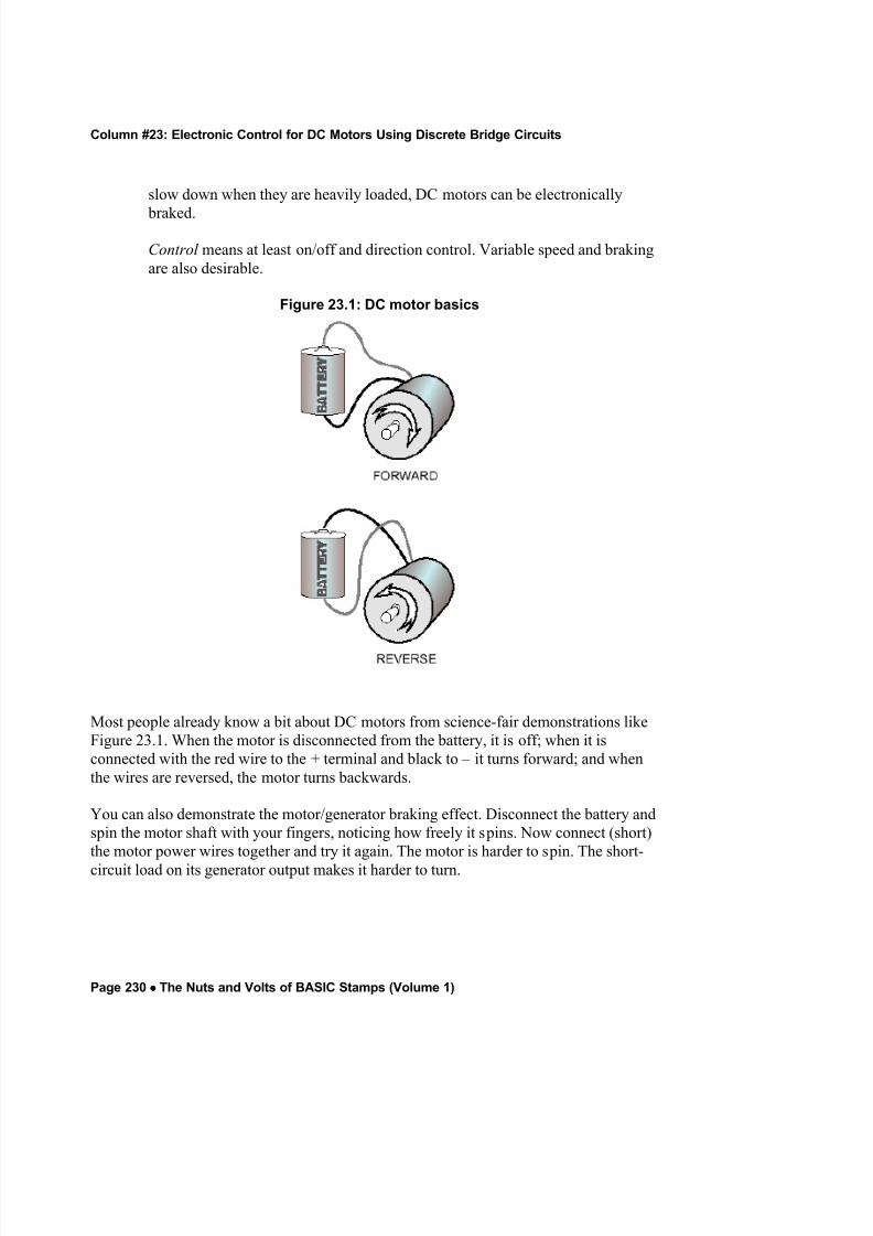
Figure 23.1: DC motor basics
Most people already know a bit about DC motors from science-fair demonstrations likeFigure 23.1. When the motor is disconnected from the battery, it is off; when it isconnected with the red wire to the + terminal and black to – it turns forward; and whenthe wires are reversed, the motor turns backwards.
You can also demonstrate the motor/generator braking effect. Disconnect the battery andspin the motor shaft with your fingers, noticing how freely it spins. Now connect (short)the motor power wires together and try it again. The motor is harder to spin. The short-
circuit load on its generator output makes it harder to turn.
8/2/2019 nv23
http://slidepdf.com/reader/full/nv23 3/14
Column #23: Electronic Control for DC Motors Using Discrete Bridge Circuits
The Nuts and Volts of BASIC Stamps (Volume 1) •••• Page 231
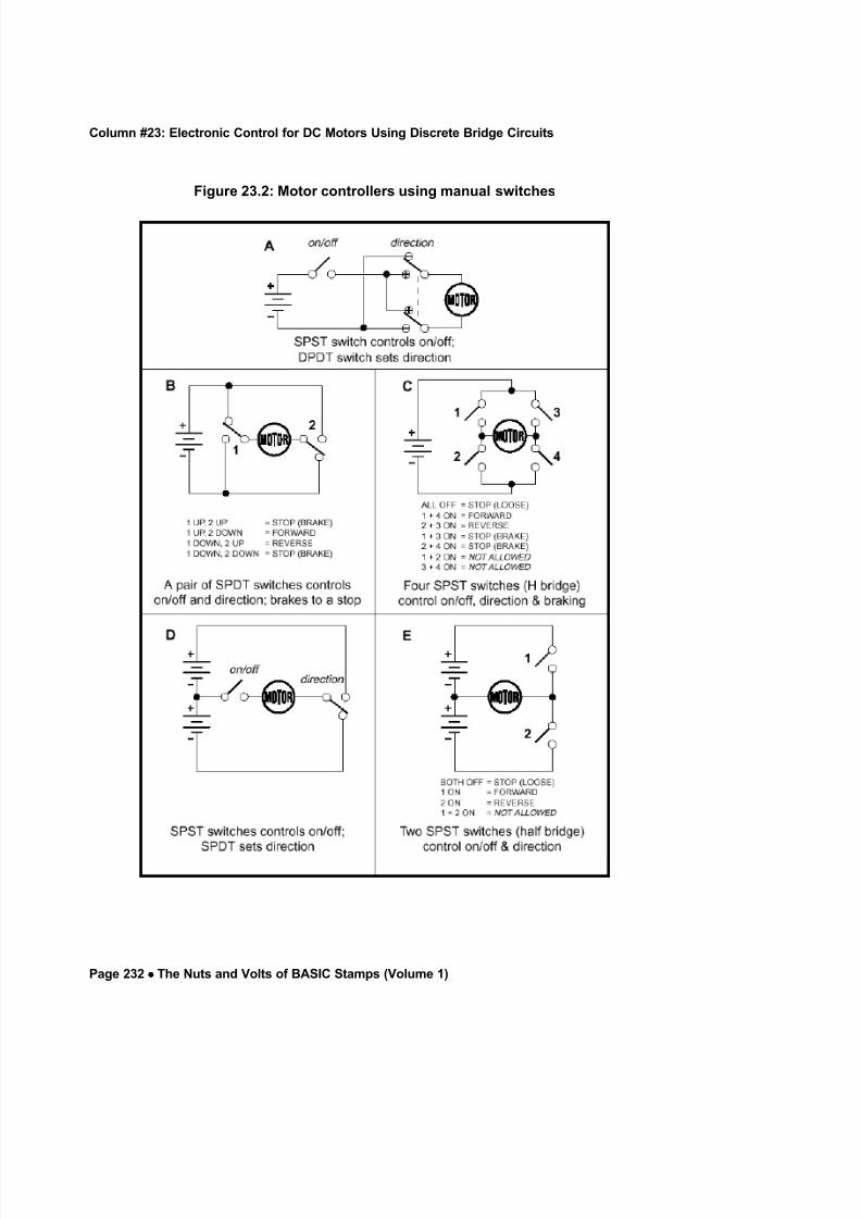
Manual Motor Controllers
Figure 23.2 shows how our understanding of DC motor control translates into fivemanual motor-control circuits using switches.
Figure A is the most closely related to the science-fair demo. A single-pole, single-throw(SPST) switch turns power to the motor on or off, while a double-pole, double-throw(DPDT) switch controls the polarity of the motor connections.
Don’t be scared off by this talk about poles and throws. The component we call a switchcan actually contain several switches, all activated by the same handle. These joinedswitches are indicated on a schematic by a dotted line joining their symbols. Each joinedswitch is referred to as a pole. So a switch component containing two switches is a
double-pole unit.
Throws refer to the number of circuits a switch can make. An ordinary on/off switchmakes or breaks just one connection, so it’s a single-throw switch. The direction switchesat the top of Figure 23.2 select one of two connections, so they are double-throw
switches.
Figure B uses a pair of SPDT switches to control direction and on/off. If the two switchesare set so that they both connect to the same power-supply rail, the circuit brakes themotor using the motor/generator principle. Figure C is very similar, but uses four SPSTswitches. These switches must be turned on and off in specific combinations to run andstop the motor. Note that a couple of switch settings are not allowed, because they wouldshort out the power supply.
You might consider Figures D and E to be cheater’s solutions to the motor-controller problem. They use a second battery to reverse the motor, thereby simplifying thearrangement of switches. However, extra batteries mean extra weight and expense. Andthe batteries may wear out at different rates, since in most applications motors spendmore time going in one direction or the other. Still, the half-bridge design is worthknowing, because it can be very useful in cheap, efficient, dual-motor designs.
8/2/2019 nv23
http://slidepdf.com/reader/full/nv23 4/14
Column #23: Electronic Control for DC Motors Using Discrete Bridge Circuits
Page 232 •••• The Nuts and Volts of BASIC Stamps (Volume 1)
Figure 23.2: Motor controllers using manual switches
8/2/2019 nv23
http://slidepdf.com/reader/full/nv23 5/14
Column #23: Electronic Control for DC Motors Using Discrete Bridge Circuits
The Nuts and Volts of BASIC Stamps (Volume 1) •••• Page 233
Electronic Switches
The manual motor controllers described above can all be converted to electronic (Stamp)control using one or more of the following types of electronic switches:
Relays. A relay is a mechnical switch operated by an electromagnet. The relatively smallcurrent that energizes the electromagnet (the coil) can control a larger current through therelay switch(es), known as the contact s. However, most relays are not suitable for directconnection to Stamps because even the relatively small coil current is more than theStamp’s pins can supply. This can be overcome through the use of a transistor switch to
beef up current handling. See the Transistors section below or Stamp Applications no. 6for more info.
Relays have two useful properties for small motor controllers: (1) Their contacts havevery low on-resistance, meaning that very little power is wasted. (2) They are available in
just about any combination of poles and throws you can imagine. As we’ll see, solid-statemultipole/multithrow switches are usually built up from many SPST units.
On the downside again, relays are slow, make noise, and wear out. They are almostuseless in schemes that switch power on and off rapidly to control motor speed (duty-cycle control).
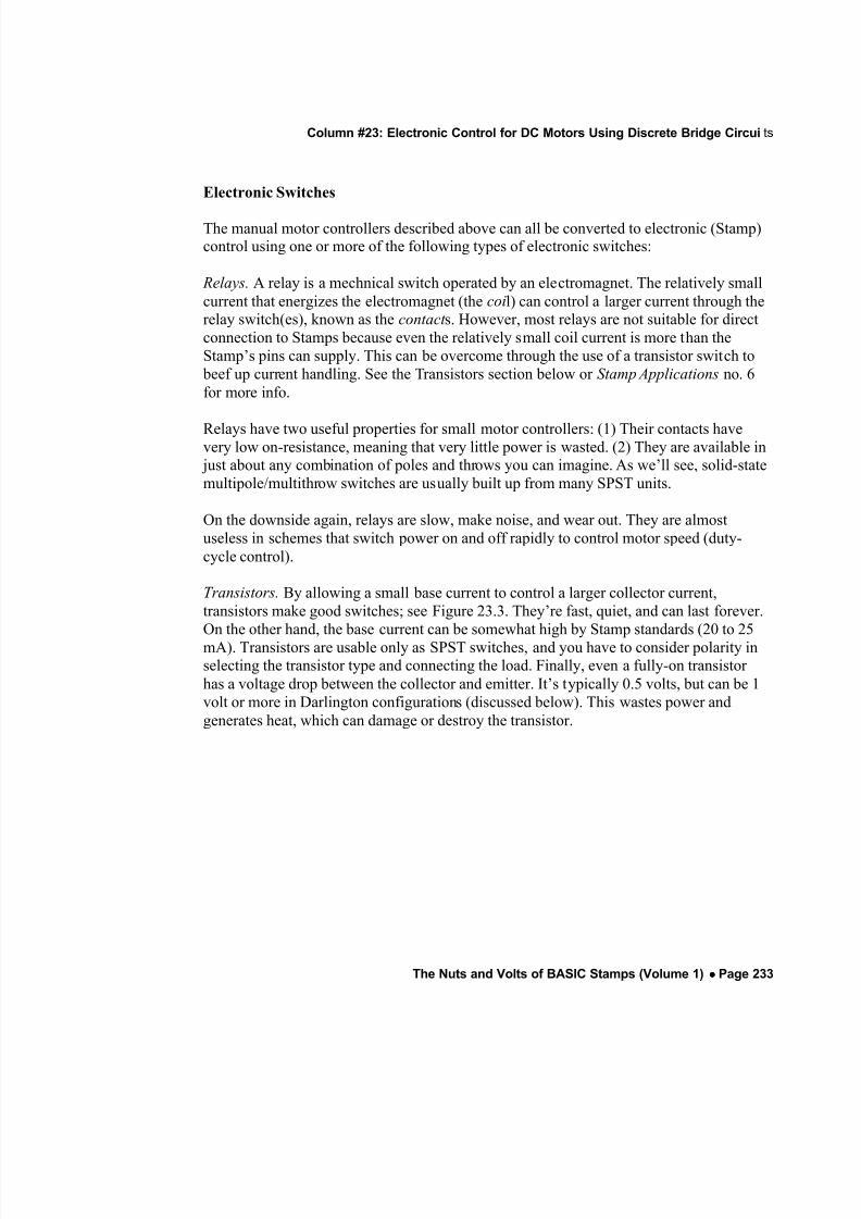
Transistors. By allowing a small base current to control a larger collector current,transistors make good switches; see Figure 23.3. They’re fast, quiet, and can last forever.On the other hand, the base current can be somewhat high by Stamp standards (20 to 25mA). Transistors are usable only as SPST switches, and you have to consider polarity inselecting the transistor type and connecting the load. Finally, even a fully-on transistor has a voltage drop between the collector and emitter. It’s typically 0.5 volts, but can be 1volt or more in Darlington configurations (discussed below). This wastes power andgenerates heat, which can damage or destroy the transistor.
8/2/2019 nv23
http://slidepdf.com/reader/full/nv23 6/14
Column #23: Electronic Control for DC Motors Using Discrete Bridge Circuits
Page 234 •••• The Nuts and Volts of BASIC Stamps (Volume 1)
Figure 23.3: Transistors make good motor switches
MOSFETs. At first glance, MOSFETs (metal-oxide semiconductor field-effecttransistors) would seem to eliminate all the problems of relays and conventionaltransistors. Their control input, the gat e, draws almost no current. It switches in responseto the presence of a voltage. A turned-on MOSFET can offer an on resistance that manyrelays would envy. And reasonably priced MOSFETs are available in current ratings thatlook like a misprint—50 amps or more out of a thumbnail-sized package.
Really, the only trouble with MOSFETs is that they are at their best with supply voltagesabove 10 volts, and with control voltages higher than the supply. And if they are to be
switched on and off rapidly, you can forget about that ‘almost no gate current’ stuff because the gate acts like a pretty high capacitance. MOSFETs don’t hold up well intinkerers’ workshops where antistatic precautions (grounded work surfaces, wrist straps,etc.) are unheard of.

8/2/2019 nv23
http://slidepdf.com/reader/full/nv23 7/14
Column #23: Electronic Control for DC Motors Using Discrete Bridge Circuits
The Nuts and Volts of BASIC Stamps (Volume 1) •••• Page 235
I’ll catch some flak for saying this, but MOSFETs’ special handling and design
requirements make them unsuited to beginners’ skills. If you need this kind of highefficiency, but aren’t up to building it yourself, see the next section.
Integrated, Kit, and Packaged Motor Controllers. There are lots of ICs and black boxesthat make motor-controller design more of a shopping challenge than a design exercise.Two ICs that are popular with robotics enthusiasts are the L293D and LMD18200. WirzElectronics sells these parts and provides design information via the Internet. Basic specsare:
L293D: motor supply voltages up to 36V, current to 1 A (2A peak). Voltagedrop across each leg of H-bridge, 1 to 2V.
LMD18200: motor supply voltages of 12 to 55V, current to 3A. On resistance of each leg of H-bridge 0.33Ω typical, 0.6Ω max.
The robotics-supply store Mondotronics offers motor-control kits that are inexpensive,educational, and easy to build. The program listing is an example of motor speed- anddirection-control using their their Mini Dual H-bridge Motor Driver kit, shown in theaccompanying photos. Mondo also carries suitable DC motor assemblies (like the Tamiyamotor/gearbox in the picture) and robotic components.
A nice feature of Mondo’s controller kits is that all have the same connector layout andinterface requirements. If you build a small robot (or motorized widget) and later want to
build a larger one, just swap motor controllers.
Packaged motor controllers, called electronic speed controls (ESCs), are available fromhobby shops for use in remote-control cars, boats, etc. Some ESCs are brutes capable of switching 10s or 100s of amperes. Best of all, accept just a servo-control pulse train inputto operate. That’s a 1- to 2-ms pulse repeated 60 times a second. As the Stampapplication notes show, it’s relatively easy to generate these pulses from PBASIC. If youneed to control more than one motor, or your PBASIC program is too tied up to meet the60-pulse-per-second requirement, you can use my company’s Mini SSC (serial servocontroller) to generate eight continuous pulse streams. See Sources for cataloginformation.
8/2/2019 nv23
http://slidepdf.com/reader/full/nv23 8/14
Column #23: Electronic Control for DC Motors Using Discrete Bridge Circuits
Page 236 •••• The Nuts and Volts of BASIC Stamps (Volume 1)
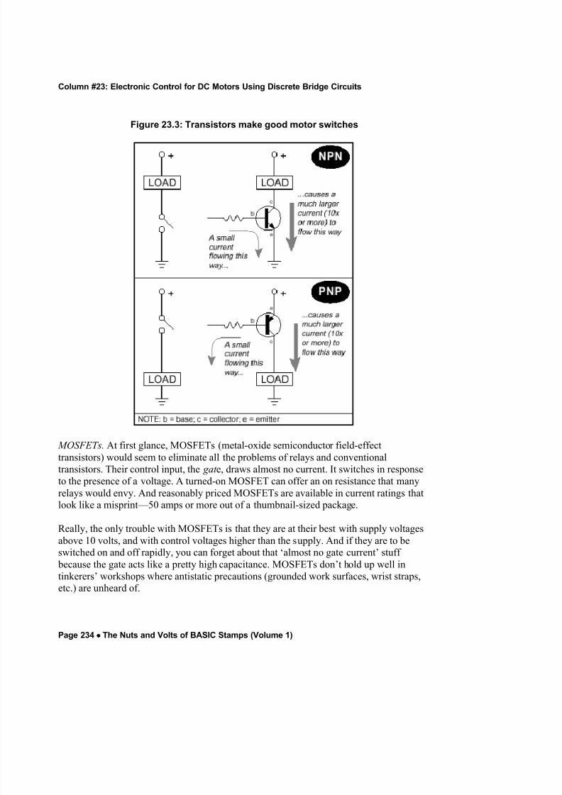
Figure 23.4: Controller combines IC driver with DPDT relays
Example Circuits
Figures 23.4, 23.5 and 23.6 are representative motor-control designs derived from theideas presented Figure 23.2A, 23.2C and 23.2E. These are tested, proven circuits suitablefor use with small DC motors. Even if your application requires a much larger motor, itmakes sense to get your feet wet with smaller motors so that you can begin to understand
some of the issues involved. And a small geared motor assembly, like the Tamiya unitshown in the photo, has enough oomph to propel robots up to a couple of pounds atreasonable speeds.
8/2/2019 nv23
http://slidepdf.com/reader/full/nv23 9/14
Column #23: Electronic Control for DC Motors Using Discrete Bridge Circuits
The Nuts and Volts of BASIC Stamps (Volume 1) •••• Page 237
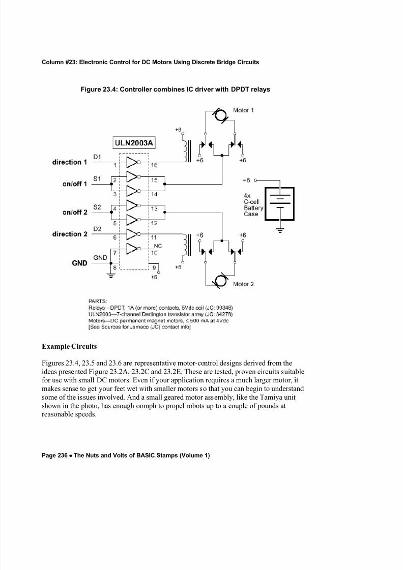
Figure 23.5: Mondotronics H-bridge
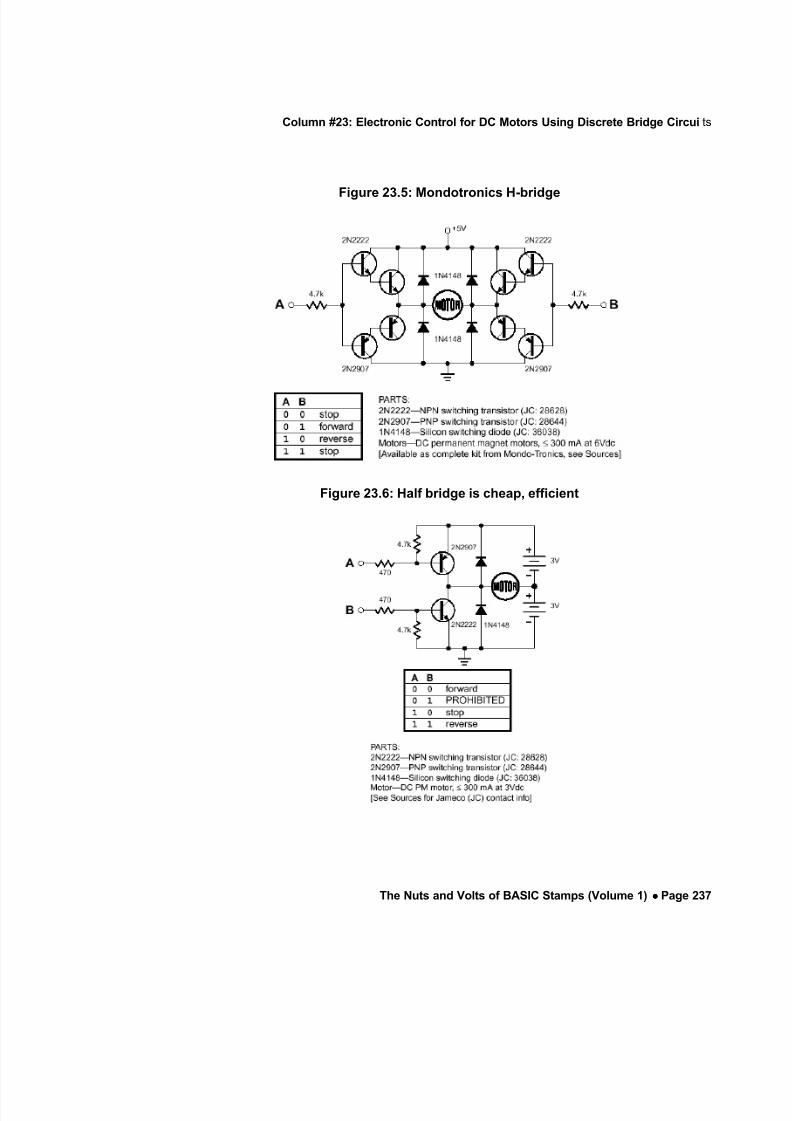
Figure 23.6: Half bridge is cheap, efficient
8/2/2019 nv23
http://slidepdf.com/reader/full/nv23 10/14
Column #23: Electronic Control for DC Motors Using Discrete Bridge Circuits
Page 238 •••• The Nuts and Volts of BASIC Stamps (Volume 1)
This particular motor was used to test the control circuits presented here, and draws
approximately 250mA at 3.0 Vdc. Note that current is dependent on voltage, so thefigures in the descriptions below are based on actual measurements.
Figure 23.4, Dual Relay Controller. This design uses DPDT relays to control motor direction, and an IC-packaged transistor array to turn the relays and motors on and off.Experienced eyes will spot an apparent error—this design gangs two of the ULN2003Darlington transistor outputs together for motor on/off control. This is normally a badidea, because slight differences in transistor characteristics will cause one of thetransistors to bear all of the load. However, because these transistors are on the samesilicon die, their characteristics and temperature are close enough to identical to make thistrick safe.
Because the transistors inside the ULN2003 are Darlingtons, they require only a small(<1mA) control current to turn on. The downside is that they have a higher-than normalvoltage drop of about 1.5 V. If the circuit is driving our sample motors, that means thatthe motors get 4.5V x 0.40A = 1.8 watts (W) of power, while 1.5V x 0.40A = 0.6 W iswasted. (This assumes no loss through the relay contacts.) So 75% of the total 2.4 W getsto the motor. To be fair, we need to also factor in the relay coil current, 4.5V x 0.1A =0.45 W to the waste (non-motor) side of the balance sheet. Now our total is 2.85 W, of which the motor gets 63%.
Figure 23.5, Darlington H-bridge. This is the circuit used in the Mondo Mini H-bridgekits. It also uses ½Darlington pairs of transistors to keep control current to approximately1mA. As with other Darlington arrangements, the penalty is increased voltage drop—Imeasured it at about 1.2 volt per conducting leg of the bridge for a total of 2.4 V (sincetwo legs of the H have to be conducting for the motor to move).
With the sample motors, the motors get 3.6V x 0.30A = 1.08W of power, while 2.4 x0.30A = 0.72 W is wasted. So 60% of the total 1.79W gets to the motor.
Figure 23.6, Half bridge. This circuit offers the pleasant combination of high efficiencyand low parts count, at the expense of splitting the battery supply into separate sectionsThe circuit takes advantage of the Stamps’ relatively high current outputs to eliminate theneed for an input transistor or Darlington. Where the previous circuits needed just 1 mAof control current, this one requires almost 10 mA. It’s a worthwhile trade for the reduced
parts count.
8/2/2019 nv23
http://slidepdf.com/reader/full/nv23 11/14
Column #23: Electronic Control for DC Motors Using Discrete Bridge Circuits
The Nuts and Volts of BASIC Stamps (Volume 1) •••• Page 239
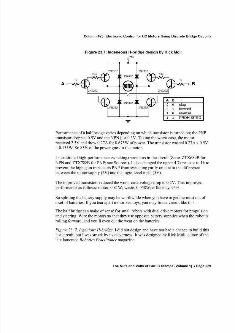
Figure 23.7: Ingeneous H-bridge design by Rick Moll
Performance of a half bridge varies depending on which transistor is turned on; the PNPtransistor dropped 0.5V and the NPN just 0.3V. Taking the worst case, the motor received 2.5V and drew 0.27A for 0.675W of power. The transistor wasted 0.27A x 0.5V= 0.135W. So 83% of the power goes to the motor.
I subsitituted high-performance switching transistors in the circuit (Zetex ZTX689B for NPN and ZTX788B for PNP; see Sources). I also changed the upper 4.7k resistor to 1k to prevent the high-gain transistors PNP from switching partly on due to the difference between the motor supply (6V) and the logic-level input (5V).
The improved transistors reduced the worst-case voltage drop to 0.2V. This improved performance as follows: motor, 0.81W; waste, 0.058W; efficiency, 93%.
So splitting the battery supply may be worthwhile when you have to get the most out of a set of batteries. If you tear apart motorized toys, you may find a circuit like this.
The half bridge can make of sense for small robots with dual drive motors for propulsionand steering. Wire the motors so that they use opposite battery supplies when the robot isrolling forward, and you’ll even out the wear on the batteries.
Figure 23. 7, Ingenious H-bridge. I did not design and have not had a chance to build this
last circuit, but I was struck by its cleverness. It was designed by Rick Moll, editor of thelate lamented Robotics Practitioner magazine.
8/2/2019 nv23
http://slidepdf.com/reader/full/nv23 12/14
Column #23: Electronic Control for DC Motors Using Discrete Bridge Circuits
Page 240 •••• The Nuts and Volts of BASIC Stamps (Volume 1)
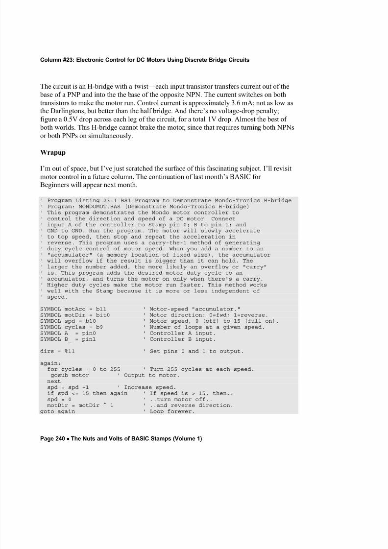
The circuit is an H-bridge with a twist—each input transistor transfers current out of the
base of a PNP and into the the base of the opposite NPN. The current switches on bothtransistors to make the motor run. Control current is approximately 3.6 mA; not as low asthe Darlingtons, but better than the half bridge. And there’s no voltage-drop penalty;figure a 0.5V drop across each leg of the circuit, for a total 1V drop. Almost the best of
both worlds. This H-bridge cannot brake the motor, since that requires turning both NPNsor both PNPs on simultaneously.
Wrapup
I’m out of space, but I’ve just scratched the surface of this fascinating subject. I’ll revisitmotor control in a future column. The continuation of last month’s BASIC for Beginners will appear next month.
' Program Listing 23.1 BS1 Program to Demonstrate Mondo-Tronics H-bridge' Program: MONDOMOT.BAS (Demonstrate Mondo-Tronics H-bridge)' This program demonstrates the Mondo motor controller to' control the direction and speed of a DC motor. Connect' input A of the controller to Stamp pin 0; B to pin 1; and' GND to GND. Run the program. The motor will slowly accelerate' to top speed, then stop and repeat the acceleration in' reverse. This program uses a carry-the-1 method of generating' duty cycle control of motor speed. When you add a number to an' "accumulator" (a memory location of fixed size), the accumulator' will overflow if the result is bigger than it can hold. The' larger the number added, the more likely an overflow or "carry"' is. This program adds the desired motor duty cycle to an' accumulator, and turns the motor on only when there's a carry.' Higher duty cycles make the motor run faster. This method works' well with the Stamp because it is more or less independent of' speed.
SYMBOL motAcc = b11 ' Motor-speed "accumulator."SYMBOL motDir = bit0 ' Motor direction: 0=fwd; 1=reverse.SYMBOL spd = b10 ' Motor speed, 0 (off) to 15 (full on).SYMBOL cycles = b9 ' Number of loops at a given speed.SYMBOL A_ = pin0 ' Controller A input.SYMBOL B_ = pin1 ' Controller B input.
dirs = %11 ' Set pins 0 and 1 to output.
again:for cycles = 0 to 255 ' Turn 255 cycles at each speed.gosub motor ' Output to motor.
nextspd = spd +1 ' Increase speed.if spd <= 15 then again ' If speed is > 15, then..spd = 0 ' ..turn motor off..motDir = motDir ^ 1 ' ..and reverse direction.
goto again ' Loop forever.
8/2/2019 nv23
http://slidepdf.com/reader/full/nv23 13/14
Column #23: Electronic Control for DC Motors Using Discrete Bridge Circuits
The Nuts and Volts of BASIC Stamps (Volume 1) •••• Page 241
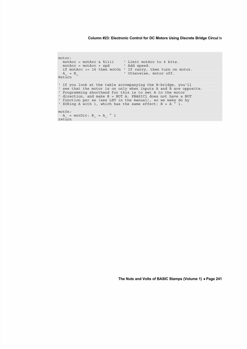
motor:
motAcc = motAcc & %1111 ' Limit motAcc to 4 bits.motAcc = motAcc + spd ' Add speed.if motAcc >= 16 then motOn ' If carry, then turn on motor.
A_ = B_ ' Otherwise, motor off.Return
' If you look at the table accompanying the H-bridge, you'll' see that the motor is on only when inputs A and B are opposite.' Programming shorthand for this is to set A to the motor' direction, and make B = NOT A. PBASIC1 does not have a NOT' function per se (see LET in the manual), so we make do by' XORing A with 1, which has the same effect: B = A ^ 1.
motOn: A_ = motDir: B_ = A_ ^ 1
return

8/2/2019 nv23
http://slidepdf.com/reader/full/nv23 14/14


