Embed Size (px)
Citation preview
80
Int. J. Mech. Eng. & Rob. Res. 2014 Rahul S and Nadeera M, 2014
ISSN 2278 – 0149 www.ijmerr.com
Vol. 3, No. 4, October, 2014
© 2014 IJMERR. All Rights Reserved
Research Paper
NUMERICAL SIMULATION OF GRINDING
FORCES BY SIMULINK
Rahul S1* and Nadeera M2
*Corresponding Author: Rahul S � [email protected]
Grinding is one of the main methods of precision machining. Grinding wheel wear, dynamicperformance of the manufacture equipment, geometric accuracy and surface quality of workpiece are greatly influenced by grinding forces, so some considerable research developmentsin calculating grinding force were made by various authors. Grinding forces are composed ofchip formation force and sliding force. In surface grinding a new mathematical model of grindingforces is developed. Effectiveness of this model is proved by comparison of the experimentalresults and the model calculation results. Static chip formation energy and dynamic chip formationenergy are mainly divided chip formation energy, which is mainly influenced by heat in the metalremoval process,shear strain rate and shear strain. By analyzing the relationship between specificchip formation energy and chip formation force a formula for calculating the chip formation forceis proposed. A new formula for calculating sliding force considering the influence of processingparameters on friction coefficient is obtained as a combined achievements of other researchers.By using Simulink software the experimental data’s are validated. Thus validate the correctnessand effectiveness of proposed grinding force model.
Keywords: Grinding, Grinding Force model, Tangential grinding force, Normal grinding force
INTRODUCTION
The most common form of abrasive machi-ning is grinding. This is a material cuttingprocess which engages an abrasive toolwhose cutting elements are grains of abrasivematerial known as grit. Grits are charac-terized by sharp cutting points, high hot hard-ness, and chemical stability and wear resis-tance. The grits are held together by a suit-
1 Post Graduate Scholar, Department of Computer Integrated Manufacturing, T.K.M College of Engineering, Kollam, India.2 Assistant Professor, Department of Computer Integrated Manufacturing, T.K.M College of Engineering, Kollam, India.
able bonding material to give shape of anabrasive tool.
Advantages
• A grinding wheel requires two types ofspecification
• dimensional accuracy
• good surface finish
• good form and locational accuracy
81
Int. J. Mech. Eng. & Rob. Res. 2014 Rahul S and Nadeera M, 2014
• applicable to both hardened andunhardened material
Applications
• Surface finishing
• Slitting and parting
• Descaling, deburring
• Stock removal (abrasive milling)finishing of flat as well as cylindricalsurface
• Grinding of tools, cutters andresharpening of the same.
GRINDING WHEEL AND
WORKPIECE INTERACTION
The bulk grinding wheel-work piece inter-action can be divided into the following
1. grit-workpiece (forming chip)
2. chip-bond
3. chip-work piece
4. bond-work piece
Except the grit work piece interaction isexpected to produce chip, the remaining threeundesirably increase the grinding force andpower requirement. Therefore, efforts shouldalways be made to maximize grit-work pieceinteraction leading to chip formation and to
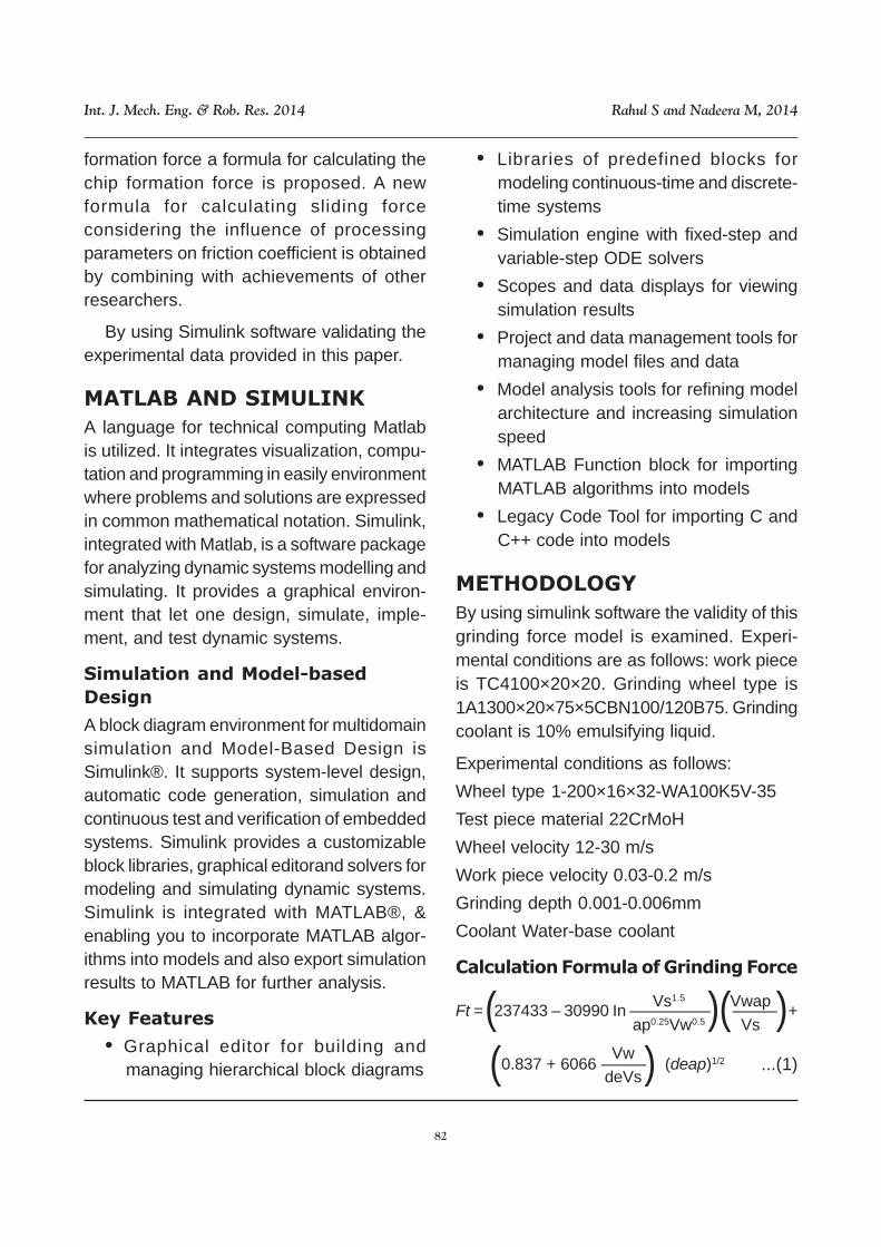
minimize the rest for best utilization of theavailable power.
NEED FOR GRINDING FORCE
MODELLING
Grinding is one of the main methods ofprecision machining. Grinding wheel wear,dynamic performance of the manufactureequipment, geometric accuracy and surfacequality of work piece are greatly influencedby grinding forces, so some considerableresearch developments in calculatinggrinding force were made by various authors.
Grinding forces are composed of chipformation force and sliding force. In surfacegrinding a new mathematical model ofgrinding forces is developed. Effectivenessof this model is proved by comparison of theexperimental results and the model calcu-lation results. Static chip formation energyand dynamic chip formation energy are themainly divided chip formation energy whichis mainly influenced by heat in the metalremoval process shear strain and shear strainrate . By analyzing the relationship betweenspeci-fic chip formation energy and chip
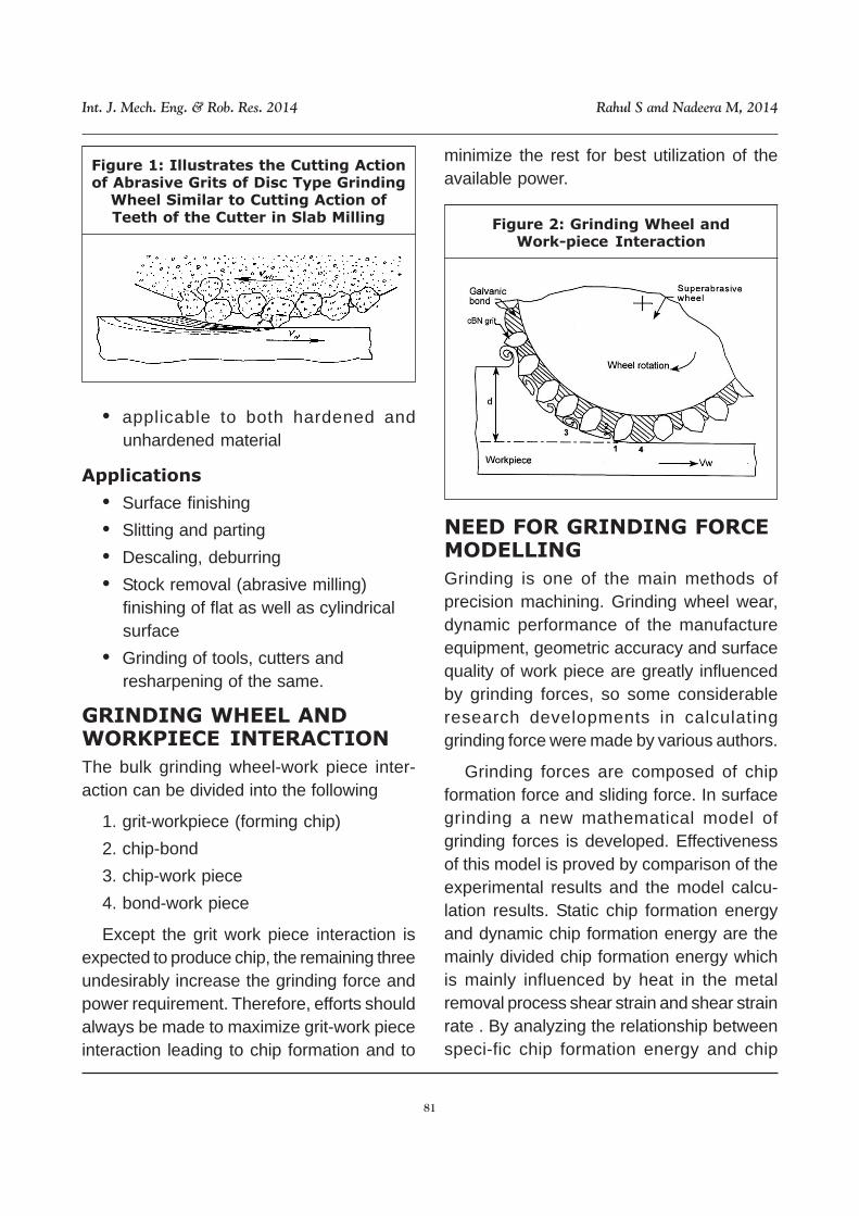
Figure 2: Grinding Wheel andWork-piece Interaction
Figure 1: Illustrates the Cutting Actionof Abrasive Grits of Disc Type Grinding
Wheel Similar to Cutting Action ofTeeth of the Cutter in Slab Milling
82
Int. J. Mech. Eng. & Rob. Res. 2014 Rahul S and Nadeera M, 2014
formation force a formula for calculating thechip formation force is proposed. A newformula for calculating sliding forceconsidering the influence of processingparameters on friction coefficient is obtainedby combining with achievements of otherresearchers.
By using Simulink software validating theexperimental data provided in this paper.
MATLAB AND SIMULINK
A language for technical computing Matlabis utilized. It integrates visualization, compu-tation and programming in easily environmentwhere problems and solutions are expressedin common mathematical notation. Simulink,integrated with Matlab, is a software packagefor analyzing dynamic systems modelling andsimulating. It provides a graphical environ-ment that let one design, simulate, imple-ment, and test dynamic systems.
Simulation and Model-based
Design
A block diagram environment for multidomainsimulation and Model-Based Design isSimulink®. It supports system-level design,automatic code generation, simulation andcontinuous test and verification of embeddedsystems. Simulink provides a customizableblock libraries, graphical editorand solvers formodeling and simulating dynamic systems.Simulink is integrated with MATLAB®, &enabling you to incorporate MATLAB algor-ithms into models and also export simulationresults to MATLAB for further analysis.
Key Features
• Graphical editor for building andmanaging hierarchical block diagrams
• Libraries of predefined blocks formodeling continuous-time and discrete-time systems
• Simulation engine with fixed-step andvariable-step ODE solvers
• Scopes and data displays for viewingsimulation results
• Project and data management tools formanaging model files and data
• Model analysis tools for refining modelarchitecture and increasing simulationspeed
• MATLAB Function block for importingMATLAB algorithms into models
• Legacy Code Tool for importing C andC++ code into models
METHODOLOGY
By using simulink software the validity of thisgrinding force model is examined. Experi-mental conditions are as follows: work pieceis TC4100×20×20. Grinding wheel type is1A1300×20×75×5CBN100/120B75. Grindingcoolant is 10% emulsifying liquid.
Experimental conditions as follows:
Wheel type 1-200×16×32-WA100K5V-35
Test piece material 22CrMoH
Wheel velocity 12-30 m/s
Work piece velocity 0.03-0.2 m/s
Grinding depth 0.001-0.006mm
Coolant Water-base coolant
Calculation Formula of Grinding Force
Ft = 237433 – 30990 In ––––––––– ––––– +( (( (Vwap
Vs
(0.837 + 6066 ––––– (deap)1/2Vw
deVs ( ...(1)
Vs1.5
ap0.25Vw0.5
83
Int. J. Mech. Eng. & Rob. Res. 2014 Rahul S and Nadeera M, 2014
The deviation between experimental data andcalculation data, which depend on the grind-ing force formula proposed, is validated byusing simulink. Graphs are plotted with abovecondition and results obtained in the journalpaper are validated.
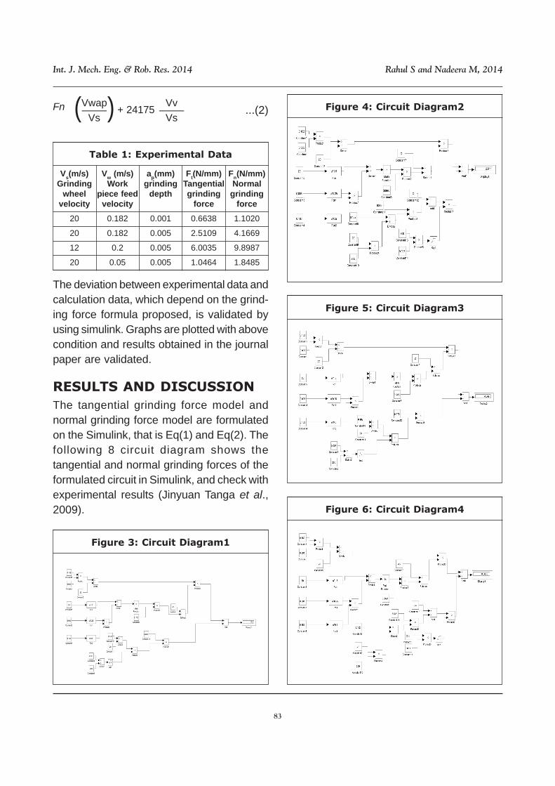
RESULTS AND DISCUSSION
The tangential grinding force model andnormal grinding force model are formulatedon the Simulink, that is Eq(1) and Eq(2). Thefollowing 8 circuit diagram shows thetangential and normal grinding forces of theformulated circuit in Simulink, and check withexperimental results (Jinyuan Tanga et al.,2009).
Table 1: Experimental Data
Vs(m/s)Grinding
wheelvelocity
20
20
12
20
Vw (m/s)Work
piece feedvelocity
0.182
0.182
0.2
0.05
ap(mm)grinding
depth
0.001
0.005
0.005
0.005
Ft(N/mm)Tangentialgrinding
force
0.6638
2.5109
6.0035
1.0464
Fn(N/mm)Normal
grindingforce
1.1020
4.1669
9.8987
1.8485
Figure 3: Circuit Diagram1
Figure 4: Circuit Diagram2
Figure 5: Circuit Diagram3
Figure 6: Circuit Diagram4
( (–––– + 24175 ––––Vv
Vs...(2)Fn Vwap
Vs
84
Int. J. Mech. Eng. & Rob. Res. 2014 Rahul S and Nadeera M, 2014
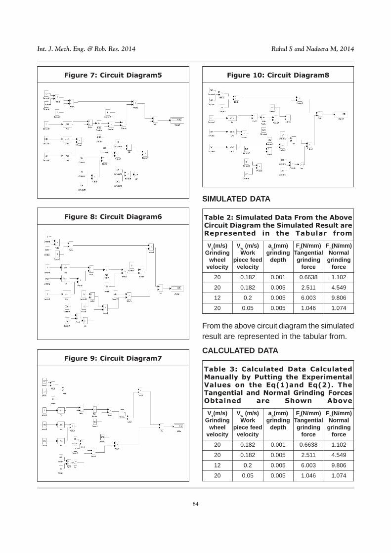
Figure 7: Circuit Diagram5
Figure 8: Circuit Diagram6
Figure 9: Circuit Diagram7
Figure 10: Circuit Diagram8
Table 2: Simulated Data From the AboveCircuit Diagram the Simulated Result areRepresented in the Tabular from
Vs(m/s)Grinding
wheelvelocity
20
20
12
20
Vw (m/s)Work
piece feedvelocity
0.182
0.182
0.2
0.05
ap(mm)grinding
depth
0.001
0.005
0.005
0.005
Ft(N/mm)Tangentialgrinding
force
0.6638
2.511
6.003
1.046
Fn(N/mm)Normalgrinding
force
1.102
4.549
9.806
1.074
Table 3: Calculated Data CalculatedManually by Putting the ExperimentalValues on the Eq(1)and Eq(2). TheTangential and Normal Grinding ForcesObtained are Shown Above
Vs(m/s)Grinding
wheelvelocity
20
20
12
20
Vw (m/s)Work
piece feedvelocity
0.182
0.182
0.2
0.05
ap(mm)grinding
depth
0.001
0.005
0.005
0.005
Ft(N/mm)Tangentialgrinding
force
0.6638
2.511
6.003
1.046
Fn(N/mm)Normalgrinding
force
1.102
4.549
9.806
1.074
SIMULATED DATA
From the above circuit diagram the simulatedresult are represented in the tabular from.
CALCULATED DATA
85
Int. J. Mech. Eng. & Rob. Res. 2014 Rahul S and Nadeera M, 2014
Calculated manually by putting the experi-mental values on the Eq(1)and Eq(2).Thetangential and normal grinding forcesobtained are shown above.
CONCLUSION
By using simulink software the equivalentcircuit diagram for equations of tangentialforce (Ft) and normal force (Fn) are drawn.By putting the values of grinding wheelvelocity (Vs), work piece feedvelocity(Vw),grinding depth (ap), de equivalentdiameter of wheel in simulink the valuesobtained are compared with the experimentaldata. The result obtained for all values exceptone value are same. By using MATLABsoftware graphs are plotted the graphsobtained are similar to referred graphs. Theresult of simulated and calculated data's arecoincide with the experimental data. Thisproves the correctness and effectiveness ofproposed grinding force model.
REFERENCES
1. Changsheng Guo (2012), “Modelling andSimulation of Mold and Die Grinding”,Journal of Manufacturing Science andEngineering (ASME), Vol. 134.
2. Eric C Johnson, Rui Li, and Albert J Shih(2008), “Design of Experiments BasedForce Modeling of the Face GrindingProcess”, Transactions of NAMRI/SME,Vol. 36.
3. I Garitaonandiaa, J Albizurib and J MHernandez-Vazqueza (2013), “Redesignof an Active System of Vibration Control
in a Centerless Grinding Machine:Numerical Simulation and PracticalImplementation”, Precision EngineeringAccepted.
4. J A Badger and A A Torrance (2000), “AComparison of two Models to PredictGrinding Forces from Wheel SurfaceTopography”, International Journal ofMachine Tools & Manufacture, Vol. 40,pp. 1099-1120.
5. Jae-Seob Kwak and Man-Kyung Ha(2001), “Force Modelling and MachiningCharacteristics of the IntermittentGrinding Wheels”, KSME InternationalJournal, Vol. 15, No. 3, pp. 351-356.
6. Jinyuan Tanga, Jin Dua and YongpingChena (2009), “Modeling and Experi-mental Study of Grinding Forces in Sur-face Grinding”, Journal of Materials Pro-cessing Technology, Vol. 2 0 9, pp. 2847-2854.
7. Kuan-Ming Li, Yang-Ming Hu, Zhong-YiYang and Ming-Yuan Chen (2012),“Experimental Study on Vibration-Assisted Grinding”, Journal of Manufac-turing Science and Engineering (ASME),Vol. 134.
8. Marco Leonesioa, Paolo Parentib, AlbertoCassinaria and Giacomo Bianchia(2012), “A Time-domain Surface GrindingModel for Dynamic Simulation”, ProcediaCIRP, Vol. 4, pp. 166 -171.
9. S Malkin1 and C Guo (2007), “ThermalAnalysis of Grinding”, CIRP, Vol. 56, No.2.