Embed Size (px)
Citation preview
1
BBAA VI International Colloquium on:
Bluff Bodies Aerodynamics & Applications
Milano, Italy, July, 20-24 2008
NUMERICAL SIMULATION OF ACTIVE FLOW CONTROL BASED
ON STREAMWISE VORTICES FOR A BLUNT TRAILING EDGE
AIRFOIL
Arash Naghib Lahouti and Horia Hangan
The Boundary Layer Wind Tunnel Laboratory
The University of Western Ontario, London, Ontario, N6A 5B9, Canada
e-mails: [email protected], [email protected]
Keywords: Blunt Trailing Edge Airfoil, wake, von Kármán vortex street, Streamwise Vortic-
ity, Flow Control, Numerical Simulation
Abstract. Numerical simulations of the flow around a blunt trailing edge airfoil are carried
out to identify the three dimensional structure of wake vorticity. Based on the results of the
simulations, an active flow control mechanism is proposed to enhance the wake streamwise
vorticity. The flow control mechanism involves injection of small amounts of secondary flow
at the base of the airfoil, with a spanwise spacing which is proportional to the natural spac-
ing of streamwise vortices. As a result of amplification of streamwise vorticity, the formation
region is elongated and the von Kármán vortex street is disorganized. Amplitude of the fluc-
tuating aerodynamic forces is also decreased considerably. The proposed flow control
mechanism provides a basis for development of a more efficient reactive control system which
would involve sensing of flow parameters correlated with streamwise vorticity, to activate in-
dividual injectors on a selective basis.
Arash Naghib Lahouti and Horia Hangan
2
1 INTRODUCTION
Previous studies have shown that three-dimensional features of the wake behind blunt trail-
ing edge objects with different forebody geometries can be manipulated to disorganize and
attenuate strength of von Kármán vortices, and thereby to reduce fluctuating lift and drag
forces. Bearman and Tombazis (Ref. [1] and Ref. [2]) achieved a 34% decrease in base drag
by using a passive control technique which involved spanwise periodical protrusions at the
trailing edge of blunt trailing edge flat plate profiles. They related the drag reduction associ-
ated with mitigation of vortex shedding to the development of three dimensional structures in
the shear layer.
Darekar and Sherwin (Ref. [3]) numerically explored the effects of the amplitude and the
spanwise periodicity of the sinusoidal protrusions on aerodynamic forces of a square cylinder
with wavy leading and trailing edges. They demonstrated that when the wavelength of the
spanwise protrusions is close to the natural spanwise spacing of pairs of counter-rotating
streamwise vortices ( Zλ ), a considerable reduction in lift and drag fluctuations, which is ac-
companied by a significant reduction of Strouhal number, can be achieved, even when protru-
sions have a very small amplitude. Their numerical simulations, however, were limited to low
Reynolds numbers in the order of 210 .
The three dimensional intermediate wake flow topology at a relatively high Reynolds num-
ber of 104 has been studied experimentally for a square cylinder by Dobre and Hangan in Ref.
[4]. Based on their findings, Dobre, Hangan, and Vickery implemented a flow control scheme
based on spanwise sinusoidal perturbations in Ref. [5], and showed that the best control effi-
ciency in terms of vortex shedding mitigation is achieved when the near wake is excited by
sinusoidal perturbations spaced at a wavelength corresponding to the statistical spanwise loca-
tion of streamwise vortex pairs. The spacing ( Zλ ) was found to be d4.2 in their case, in
which d is thickness of the trailing edge. An almost similar value of dZ 2.2=λ was reported
by Hangan et al. in Ref. [6], for the intermediate wake of a circular cylinder at 3107.6Re ×= .
El-Gammal and Hangan (Ref. [7]) extended these topological findings to blunt and divergent
trailing edge airfoils, and achieved a significant attenuation of von Kármán vortices using si-
nusoidal protrusions with a wavelength equal to dZ 4.2=λ , at .103.1)Re( 4×=d
The spacing of perturbations is fixed in all passive flow control schemes mentioned above.
However, the spacing of streamwise vortices is governed by the secondary wake instability
modes. As different combinations of these modes arise at different Reynolds numbers (Ref.
[8]), one should not expect the spacing to remain constant over a broad range of Reynolds
numbers. As a result, any passive control scheme would be efficient only at the single Rey-
nolds number and inlet conditions for which it is designed.
This fact is the principal motivation for the present study, which aims at developing a flow
control system able to amplify streamwise vortices with variable spacing. When combined
with a mechanism to sense the instantaneous location of streamwise vortices, such a flow con-
trol mechanism would be able to achieve the objective of suppressing the vortex shedding
more effectively over a broader range of Reynolds numbers and flow conditions.
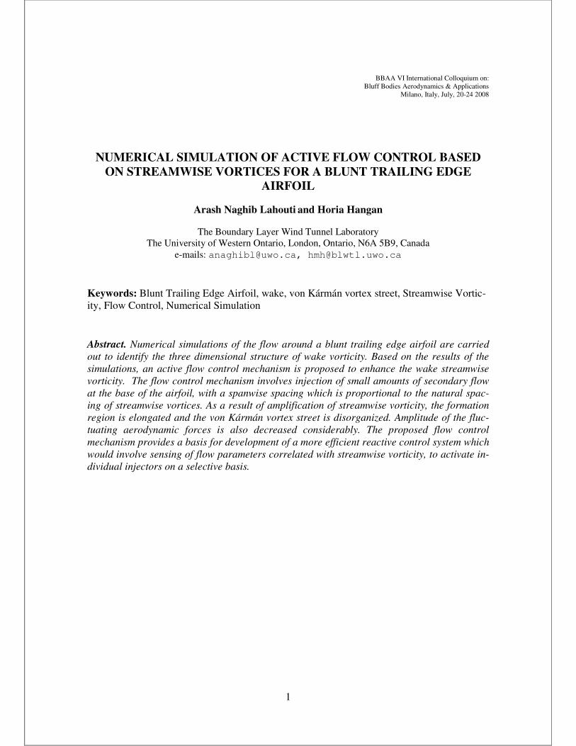
The baseline geometry over which the flow control mechanism is simulated is similar to
the one used by Tombazis and Bearman in Ref. [9]. It is a flat plate airfoil consisting of an
elliptical nose, followed by a rectangular section, as shown in Fig. (1). This geometric con-
figuration is popular in the wake control literature, because it provides the desired upstream
boundary layer velocity profile at the trailing edge, without the uncontrollable effects of
forced separation-reattachment associated with sharp leading edge corners. The geometric
model has a span of 457.2mm, a chord of 321.5mm, a semi-major axis length of 65.5mm for
Arash Naghib Lahouti and Horia Hangan
3
the elliptical section, and a total thickness of 29.4mm. These dimensions are selected in ac-
cordance with the requirements of future wind tunnel tests, and to facilitate comparison of the
results with the experimental results reported by Doddipatla et al. in Ref. [10].
Figure 1: Geometry and dimensions of the flat plate airfoil
2 THE BASE CASE (NO-CONTROL)
The following section describes details and results of numerical simulation of flow around
the blunt trailing edge airfoil introduced in the previous section. The results, which include
wake vorticity structure and the resulting aerodynamic forces, provide a basis for determining
of the flow control mechanism requirements, and to evaluate its efficiency.
2.1 The numerical model
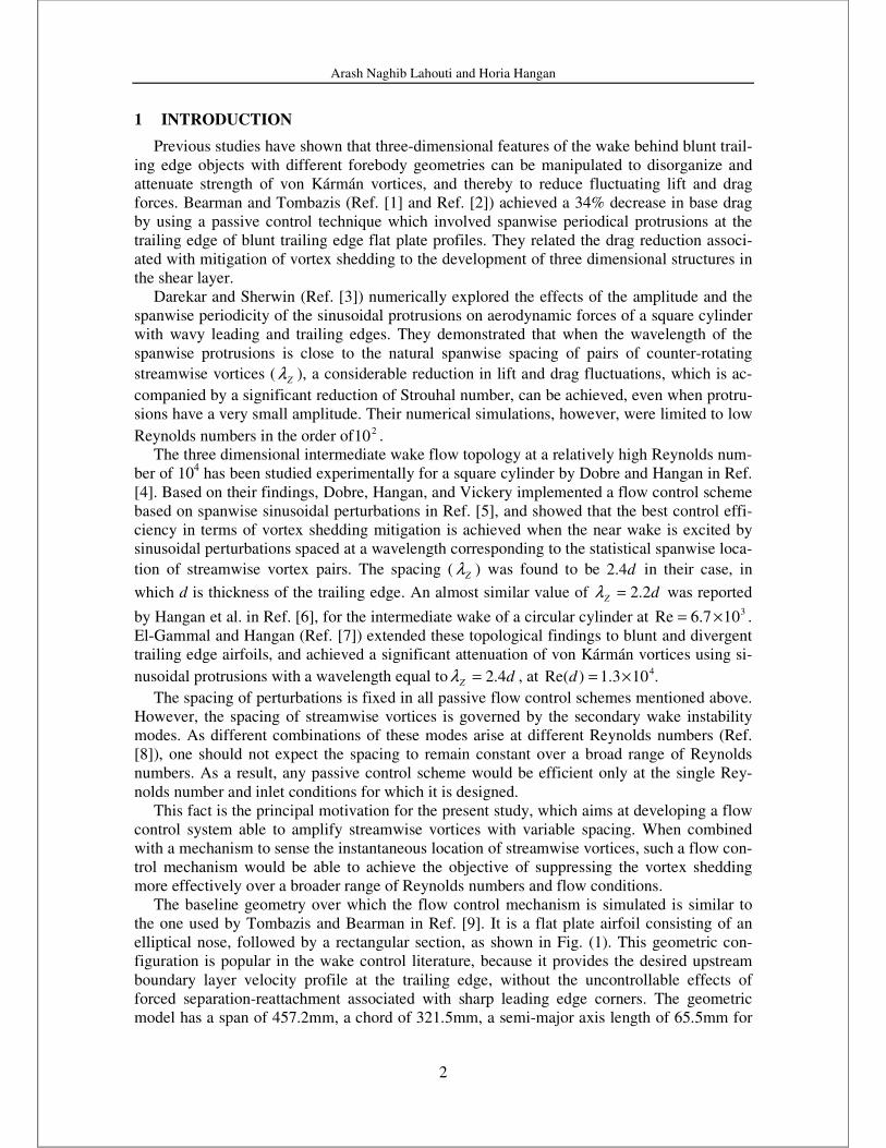
The solution domain is defined as a hexahedral volume surrounding the airfoil. The do-
main extends 5 chord lengths behind, 2 chord lengths in front, and 2 chord lengths from the
upper and lower surfaces of the airfoil. The distances between the solid surfaces of the airfoil
and the domain boundaries are selected on a trial and error basis, so that the perturbations
caused by the airfoil diminish to a level that would not cause any numerical error or inconsis-
tency when they reach the boundaries. Fig. (2) shows a schematic of the solution domain and
its boundaries.
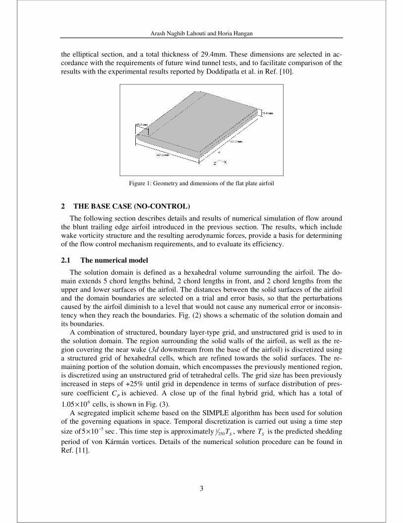
A combination of structured, boundary layer-type grid, and unstructured grid is used to in
the solution domain. The region surrounding the solid walls of the airfoil, as well as the re-
gion covering the near wake (3d downstream from the base of the airfoil) is discretized using
a structured grid of hexahedral cells, which are refined towards the solid surfaces. The re-
maining portion of the solution domain, which encompasses the previously mentioned region,
is discretized using an unstructured grid of tetrahedral cells. The grid size has been previously
increased in steps of +25% until grid in dependence in terms of surface distribution of pres-
sure coefficient PC is achieved. A close up of the final hybrid grid, which has a total of 61005.1 × cells, is shown in Fig. (3).
A segregated implicit scheme based on the SIMPLE algorithm has been used for solution
of the governing equations in space. Temporal discretization is carried out using a time step
size of sec105 5−× . This time step is approximately ST2501 , where ST is the predicted shedding
period of von Kármán vortices. Details of the numerical solution procedure can be found in
Ref. [11].
Arash Naghib Lahouti and Horia Hangan
4
Figure 2 : The solution domain and its boundaries (blue: velocity
inlet, yellow: symmetry, red: outflow)
Figure 3 : Detail of the grid in the vicinity of the base of the airfoil
2.2 Wake characteristics
Results of numerical simulations at a freestream velocity of smU /10=∞ , which is equiva-
lent to a Reynolds number of 4102Re ×=d based on the thickness of the airfoil or
5102.2Re ×=cbased on the chord, are analyzed to study the tree dimensional vorticity struc-
ture in the wake.
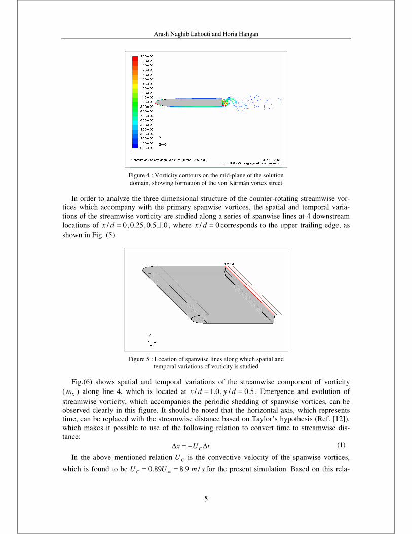
Results indicate formation of a von Kármán vortex street in the wake of the airfoil, as
shown in fig. (4). The average shedding frequency of the primary, spanwise vortices
is Hzf s 77= , which results in a Strouhal number of 23.0=St . This value of Strouhal number
is in agreement with the one found by Bearman and Tombazis (Ref. [1]) for the same geome-
try at Reynolds numbers of the same order of magnitude as the one analyzed herein.
Arash Naghib Lahouti and Horia Hangan
5
Figure 4 : Vorticity contours on the mid-plane of the solution
domain, showing formation of the von Kármán vortex street
In order to analyze the three dimensional structure of the counter-rotating streamwise vor-
tices which accompany with the primary spanwise vortices, the spatial and temporal varia-
tions of the streamwise vorticity are studied along a series of spanwise lines at 4 downstream
locations of 0.1,5.0,25.0,0/ =dx , where 0/ =dx corresponds to the upper trailing edge, as
shown in Fig. (5).
Figure 5 : Location of spanwise lines along which spatial and
temporal variations of vorticity is studied
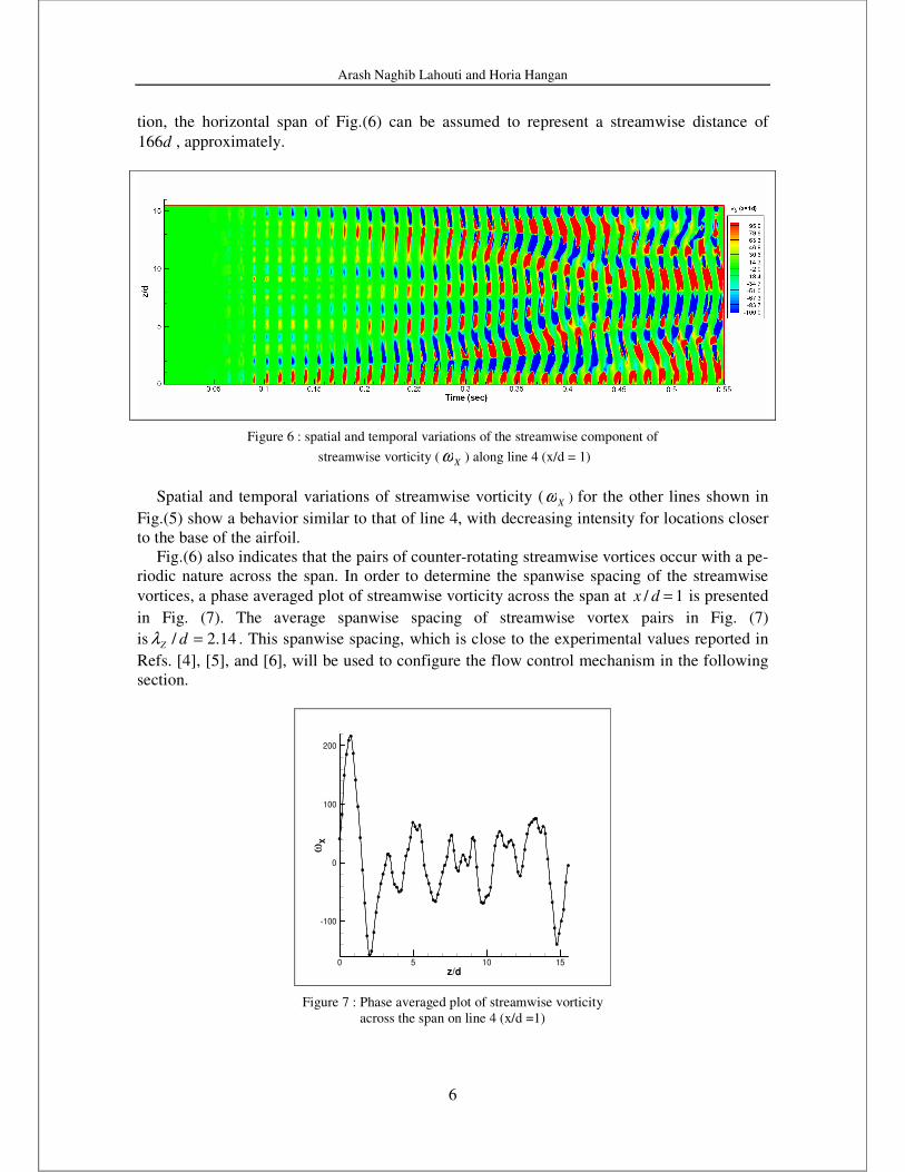
Fig.(6) shows spatial and temporal variations of the streamwise component of vorticity
( Xω ) along line 4, which is located at 5.0/,0.1/ == dydx . Emergence and evolution of
streamwise vorticity, which accompanies the periodic shedding of spanwise vortices, can be
observed clearly in this figure. It should be noted that the horizontal axis, which represents
time, can be replaced with the streamwise distance based on Taylor’s hypothesis (Ref. [12]),
which makes it possible to use of the following relation to convert time to streamwise dis-
tance:
tUx C ∆−=∆ (1)
In the above mentioned relation CU is the convective velocity of the spanwise vortices,
which is found to be smUU C /9.889.0 == ∞ for the present simulation. Based on this rela-
Arash Naghib Lahouti and Horia Hangan
6
tion, the horizontal span of Fig.(6) can be assumed to represent a streamwise distance of
d166 , approximately.
Figure 6 : spatial and temporal variations of the streamwise component of
streamwise vorticity ( Xω ) along line 4 (x/d = 1)
Spatial and temporal variations of streamwise vorticity ( Xω ) for the other lines shown in
Fig.(5) show a behavior similar to that of line 4, with decreasing intensity for locations closer
to the base of the airfoil.
Fig.(6) also indicates that the pairs of counter-rotating streamwise vortices occur with a pe-
riodic nature across the span. In order to determine the spanwise spacing of the streamwise
vortices, a phase averaged plot of streamwise vorticity across the span at 1/ =dx is presented
in Fig. (7). The average spanwise spacing of streamwise vortex pairs in Fig. (7)
is 14.2/ =dZλ . This spanwise spacing, which is close to the experimental values reported in
Refs. [4], [5], and [6], will be used to configure the flow control mechanism in the following
section.
z/d
ωX
0 5 10 15
-100
0
100
200
Figure 7 : Phase averaged plot of streamwise vorticity
across the span on line 4 (x/d =1)

Arash Naghib Lahouti and Horia Hangan
7
2.3 Aerodynamic forces
Time histories of the airfoil’s lift and drag are shown in Fig. (8). The effect of vortex shed-
ding can be observed as periodic variations of aerodynamic forces. The period of fluctuations
of drag is sf2 , since base drag is affected by base pressure variations caused by shedding of
vortices from either side of the trailing edge, which occurs twice during each shedding period
(see also Ref. [7])
The long period variations of lift and drag amplitudes can be attributed to the low-
frequency modulations of the von Kármán vortex street, which are caused by the three dimen-
sionality of vortex shedding, appearing as streamwise and vertical vorticity components. This
phenomenon, which has been investigated in detail by Wu et al. in Ref.[13], occurs with a pe-
riod which is 10 to 20 times larger than the primary vortex shedding period sT . A comparison
of the force history diagrams of Fig.(8) with spatial and temporal variations of streamwise
vorticity shown in Fig.(6) indicates that the amplitude of fluctuating forces resulting from the
primary spanwise vortices is smaller when streamwise vortices are stronger (around st 4.0= ).
This observation is in accordance with previous findings described in section 1, which suggest
that amplification of streamwise vortices can lead to attenuation of the primary spanwise vor-
tices.
Time (sec)
Lif
t,
Dra
g(N
)
0.1 0.2 0.3 0.4 0.5
-1
-0.5
0
0.5
1
DragLift
Figure 8 : Time histories of the airfoil’s lift and drag
3 FLOW CONTROL
The following section describes the flow control mechanism, which is based on amplifica-
tion of streamwise vortices. Results of numerical modeling of the flow around the airfoil in
presence of the control mechanism, which show the effect of flow control on aerodynamic
characteristics of the airfoil, are also presented and compared with those of the base case.
3.1 Flow control mechanism and modeling
Based on the observations described in sections 2.2 and 2.3 regarding the role of the
streamwise vortices and their spanwise spacing, an active flow control mechanism consisting
of a series of injection ports distributed across the span is designed. By injecting a secondary
flow at the desired locations at the trailing edge of the airfoil, the control mechanism gener-
ates vorticity that can amplify the streamwise vortices at their natural spanwise wavelength of
Arash Naghib Lahouti and Horia Hangan
8
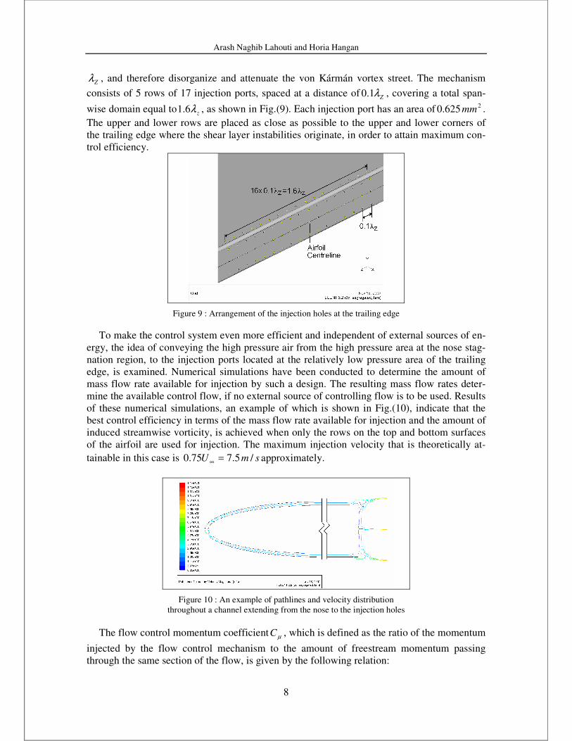
Zλ , and therefore disorganize and attenuate the von Kármán vortex street. The mechanism
consists of 5 rows of 17 injection ports, spaced at a distance of Zλ1.0 , covering a total span-
wise domain equal to zλ6.1 , as shown in Fig.(9). Each injection port has an area of 2625.0 mm .
The upper and lower rows are placed as close as possible to the upper and lower corners of
the trailing edge where the shear layer instabilities originate, in order to attain maximum con-
trol efficiency.
Figure 9 : Arrangement of the injection holes at the trailing edge
To make the control system even more efficient and independent of external sources of en-
ergy, the idea of conveying the high pressure air from the high pressure area at the nose stag-
nation region, to the injection ports located at the relatively low pressure area of the trailing
edge, is examined. Numerical simulations have been conducted to determine the amount of
mass flow rate available for injection by such a design. The resulting mass flow rates deter-
mine the available control flow, if no external source of controlling flow is to be used. Results
of these numerical simulations, an example of which is shown in Fig.(10), indicate that the
best control efficiency in terms of the mass flow rate available for injection and the amount of
induced streamwise vorticity, is achieved when only the rows on the top and bottom surfaces
of the airfoil are used for injection. The maximum injection velocity that is theoretically at-
tainable in this case is smU /5.775.0 =∞ approximately.
Figure 10 : An example of pathlines and velocity distribution
throughout a channel extending from the nose to the injection holes
The flow control momentum coefficient µC , which is defined as the ratio of the momentum
injected by the flow control mechanism to the amount of freestream momentum passing
through the same section of the flow, is given by the following relation:
Arash Naghib Lahouti and Horia Hangan
9
2
2
2
22
∞∞
==U
U
b
na
abU
naUC ii
ρ
ρµ
(2)
In the above relation, n is the number of injection ports on each side of the airfoil (17 in
this case), a is the effective diameter of each injection port, b is the span of the airfoil, and Ui
is the injection velocity. Two values of %65.1=µC (which corresponds to the maximum
achievable injection velocity of sm /5.7 ), and %82.0=µC (which corresponds to an injection
velocity half of the maximum) are modeled and studied herein.
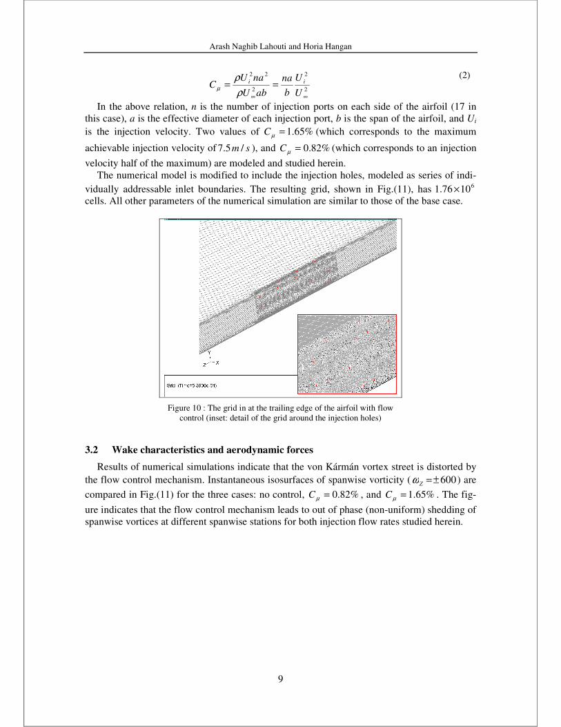
The numerical model is modified to include the injection holes, modeled as series of indi-
vidually addressable inlet boundaries. The resulting grid, shown in Fig.(11), has 61076.1 ×
cells. All other parameters of the numerical simulation are similar to those of the base case.
Figure 10 : The grid in at the trailing edge of the airfoil with flow
control (inset: detail of the grid around the injection holes)
3.2 Wake characteristics and aerodynamic forces
Results of numerical simulations indicate that the von Kármán vortex street is distorted by
the flow control mechanism. Instantaneous isosurfaces of spanwise vorticity ( 600±=Zω ) are
compared in Fig.(11) for the three cases: no control, %82.0=µC , and %65.1=µC . The fig-
ure indicates that the flow control mechanism leads to out of phase (non-uniform) shedding of
spanwise vortices at different spanwise stations for both injection flow rates studied herein.
Arash Naghib Lahouti and Horia Hangan
10
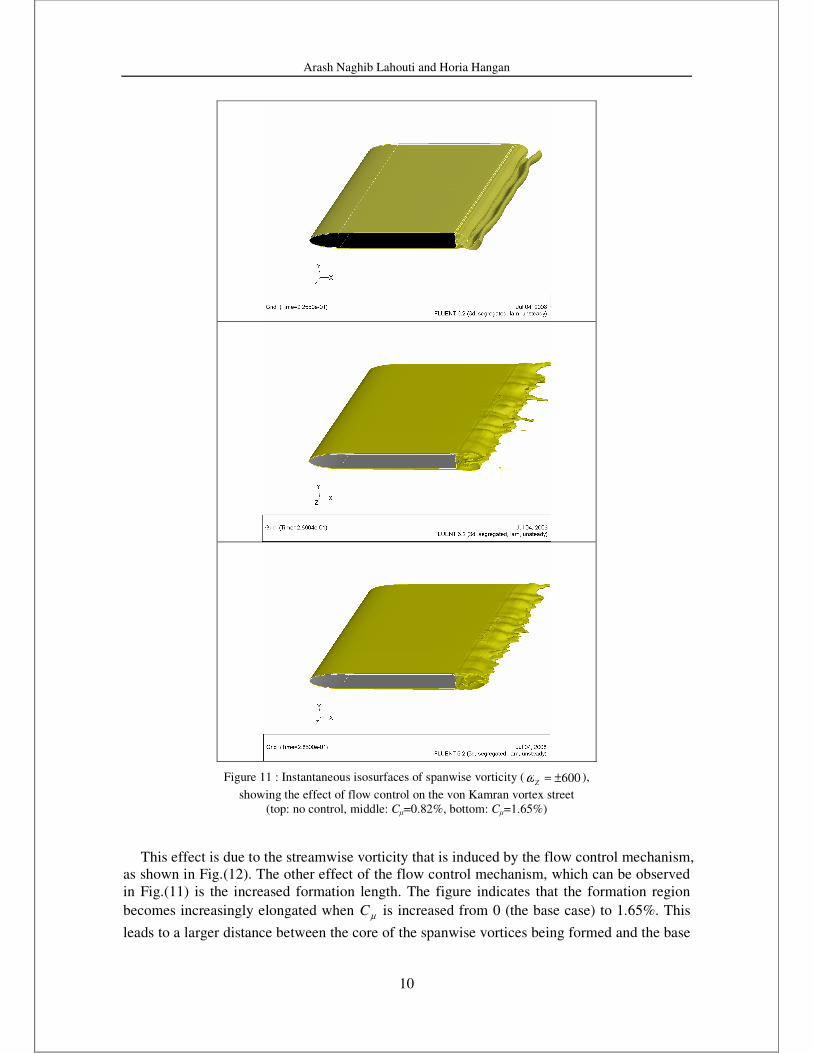
Figure 11 : Instantaneous isosurfaces of spanwise vorticity ( 600±=Zω ),
showing the effect of flow control on the von Kamran vortex street
(top: no control, middle: Cµ=0.82%, bottom: Cµ=1.65%)
This effect is due to the streamwise vorticity that is induced by the flow control mechanism,
as shown in Fig.(12). The other effect of the flow control mechanism, which can be observed
in Fig.(11) is the increased formation length. The figure indicates that the formation region
becomes increasingly elongated when µC is increased from 0 (the base case) to 1.65%. This
leads to a larger distance between the core of the spanwise vortices being formed and the base

Arash Naghib Lahouti and Horia Hangan
11
of the airfoil, which in turn leads to increased values of base pressure and reduced fluctuating
aerodynamic forces.
Figure 12 : Contours of streamwise vorticity around the injection
Holes, showing induction of streamwise vorticity by them
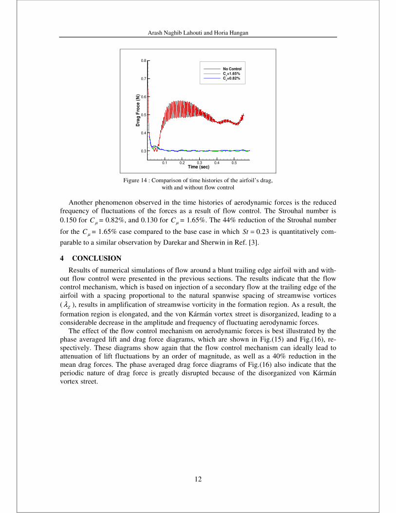
The effect of injection on aerodynamic forces is presented in Fig. (13) and Fig. (14). Time
histories of the airfoil’s lift force with and without flow control are shown in Fig.(13). For
both values of µC , lift force fluctuations are reduced by approximately one order of magnitude,
when compared to those of the base (no control) case. Figure (14) compares time histories of
the airfoil’s drag force with and without control. A maximum drag force reduction of 40% is
achieved by the flow control mechanism. This reduction is slightly larger compared to the one
reported by Tombazis and Bearman (Ref. [2]) using spanwise sinusoidal perturbations.
Time (sec)
Lif
t(N
)-
No
Co
ntr
ol
Lif
t(N
)-
Wit
hc
on
tro
l
0.1 0.2 0.3 0.4 0.5
-1
-0.5
0
0.5
1
-0.1
-0.05
0
0.05
0.1No ControlC
µ=1.65%
Cµ=0.82%
Figure 13 : Comparison of time histories of the airfoil’s lift,
with and without flow control
Arash Naghib Lahouti and Horia Hangan
12
Time (sec)
Dra
gF
roc
e(N
)
0.1 0.2 0.3 0.4 0.5
0.3
0.4
0.5
0.6
0.7
0.8
No Control
Cµ=1.65%
Cµ=0.82%
Figure 14 : Comparison of time histories of the airfoil’s drag,
with and without flow control
Another phenomenon observed in the time histories of aerodynamic forces is the reduced
frequency of fluctuations of the forces as a result of flow control. The Strouhal number is
0.150 for µC = 0.82%, and 0.130 for µC = 1.65%. The 44% reduction of the Strouhal number
for the µC = 1.65% case compared to the base case in which 23.0=St is quantitatively com-
parable to a similar observation by Darekar and Sherwin in Ref. [3].
4 CONCLUSION
Results of numerical simulations of flow around a blunt trailing edge airfoil with and with-
out flow control were presented in the previous sections. The results indicate that the flow
control mechanism, which is based on injection of a secondary flow at the trailing edge of the
airfoil with a spacing proportional to the natural spanwise spacing of streamwise vortices
( Zλ ), results in amplification of streamwise vorticity in the formation region. As a result, the
formation region is elongated, and the von Kármán vortex street is disorganized, leading to a
considerable decrease in the amplitude and frequency of fluctuating aerodynamic forces.
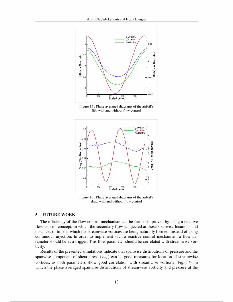
The effect of the flow control mechanism on aerodynamic forces is best illustrated by the
phase averaged lift and drag force diagrams, which are shown in Fig.(15) and Fig.(16), re-
spectively. These diagrams show again that the flow control mechanism can ideally lead to
attenuation of lift fluctuations by an order of magnitude, as well as a 40% reduction in the
mean drag forces. The phase averaged drag force diagrams of Fig.(16) also indicate that the
periodic nature of drag force is greatly disrupted because of the disorganized von Kármán
vortex street.
Arash Naghib Lahouti and Horia Hangan
13
Scaled period
Lif
t(N
)-
No
co
ntr
ol
Lif
t(N
)-
Wit
hc
on
tro
l
0 0.2 0.4 0.6 0.8 1
-1
-0.5
0
0.5
1
-0.02
-0.01
0
0.01
Cµ=0.82%
Cµ=1.65%
No Control
Figure 15 : Phase averaged diagrams of the airfoil’s
lift, with and without flow control
Scaled period
Dra
g(N
)-
No
co
ntr
ol
Dra
g(N
)-
Wit
hc
on
tro
l
0 0.2 0.4 0.6 0.8 1
0.6
0.62
0.64
0.66
0.68
0.7
0.3
00
50
.30
10
.30
15
0.3
02
Cµ=0.82%
Cµ=1.65%
No Control
Figure 16 : Phase averaged diagrams of the airfoil’s
drag, with and without flow control
5 FUTURE WORK
The efficiency of the flow control mechanism can be further improved by using a reactive
flow control concept, in which the secondary flow is injected at those spanwise locations and
instances of time at which the streamwise vortices are being naturally formed, instead of using
continuous injection. In order to implement such a reactive control mechanism, a flow pa-
rameter should be as a trigger. This flow parameter should be correlated with streamwise vor-
ticity.
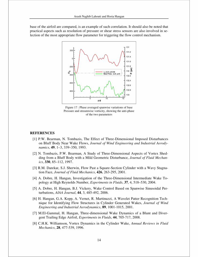
Results of the presented simulations indicate that spanwise distributions of pressure and the
spanwise component of shear stress ( XZτ ) can be good measures for location of streamwise
vortices, as both parameters show good correlation with streamwise vorticity. Fig.(17), in
which the phase averaged spanwise distributions of streamwise vorticity and pressure at the
Arash Naghib Lahouti and Horia Hangan
14
base of the airfoil are compared, is an example of such correlation. It should also be noted that
practical aspects such as resolution of pressure or shear stress sensors are also involved in se-
lection of the most appropriate flow parameter for triggering the flow control mechanism.
z/d
ωX
P(p
a)
0 5 10 15
-800
-600
-400
-200
0
200
-133
-132.8
-132.6
-132.4
-132.2
-132
-131.8
-131.6
-131.4
-131.2
-131
ωX
(x=0, y=0.5d)Base Press. (x=0, y=0)
Figure 17 : Phase averaged spanwise variations of base
Pressure and streamwise vorticity, showing the anti-phase
of the two parameters
REFERENCES
[1] P.W. Bearman, N. Tombazis, The Effect of Three-Dimensional Imposed Disturbances
on Bluff Body Near Wake Flows, Journal of Wind Engineering and Industrial Aerody-
namics, 49, 1–3, 339–350, 1993.
[2] N. Tombazis, P.W. Bearman, A Study of Three-Dimensional Aspects of Vortex Shed-
ding from a Bluff Body with a Mild Geometric Disturbance, Journal of Fluid Mechan-
ics, 330, 85–112, 1997.
[3] R.M. Darekar, S.J. Sherwin, Flow Past a Square-Section Cylinder with a Wavy Stagna-
tion Face, Journal of Fluid Mechanics, 426, 263-295, 2001.
[4] A. Dobre, H. Hangan, Investigation of the Three-Dimensional Intermediate Wake To-
pology at High Reynolds Number, Experiments in Fluids, 37, 4, 518–530, 2004.
[5] A. Dobre, H. Hangan, B.J. Vickery, Wake Control Based on Spanwise Sinusoidal Per-
turbations, AIAA Journal, 44, 3, 485-492, 2006.
[6] H. Hangan, G.A. Kopp, A. Vernet, R. Martinuzzi, A Wavelet Patter Recognition Tech-
nique for Identifying Flow Structures in Cylinder Generated Wakes, Journal of Wind
Engineering and Industrial Aerodynamics, 89, 1001-1015, 2001.
[7] M.El-Gammal, H. Hangan, Three-dimensional Wake Dynamics of a Blunt and Diver-
gent Trailing Edge Airfoil, Experiments in Fluids, 44, 705-717, 2008.
[8] C.H.K. Williamson, Vortex Dynamics in the Cylinder Wake, Annual Reviews in Fluid
Mechanics, 28, 477-539, 1996.
Arash Naghib Lahouti and Horia Hangan
15
[9] P.W. Bearman, Investigation of the Flow Behind a Two-dimensional Model with a Blunt
Trailing Edge and Fitted with Splitter Plates, Journal of Fluid Mechanics, 21, 241-255,
1965.
[10] L.S. Doddipatla, H.Hangan, V. Durgesh, J.W. Naughton, Near Wake Flow Dynamics
Resulting from Trailing Edge Spanwise Perturbations, The 4th
AIAA Flow Control Con-
ference, Seattle, Washington, USA, June 23-26, 2008.
[11] Anon., Fluent 6.2 User’s Guide, Fluent Inc., Lebanon NH, USA, 2005.
[12] J.T. Taylor, The Spectrum of Turbulence, Proceedings of the Royal Society, A 164,
1938.
[13] S.J. Wu, J.J. Miau, C.C. Hu, J.H. Chou, On Low-frequency Modulations and Three-
dimensionality in Vortex Shedding Behind a Normal Plate, Journal of Fluid Mechanics,
526, 117-146, 2005.