Embed Size (px)
Citation preview

Numerical modelling of shear connection between concrete
slab and sheeting deck
Noémi Seres
Budapest University of Technology and EconomicsDepartment of Structural Engineering
Budapest, Hungary
7th fib International PhD Symposium in Civil Engineering
2008 September 10-13, Universität Stuttgart, Germany
Introduction
• Structural arrangement
• Failure modes
Steel beam
Profile deck
Reinforced concrete slab
Frictional interlock
Mechanical interlock – rolled embossments
(I) flexural failure (II) longitudinal shear failure (III) vertical shear failure
Introduction
• Performance tests
• Scopes
(a) Full – scale test (b) Small – scale test
└ Eurocode 4
a)b)
(i) simplify the experiments
(ii) develop an advanced numerical model for the simulation
Experimental program
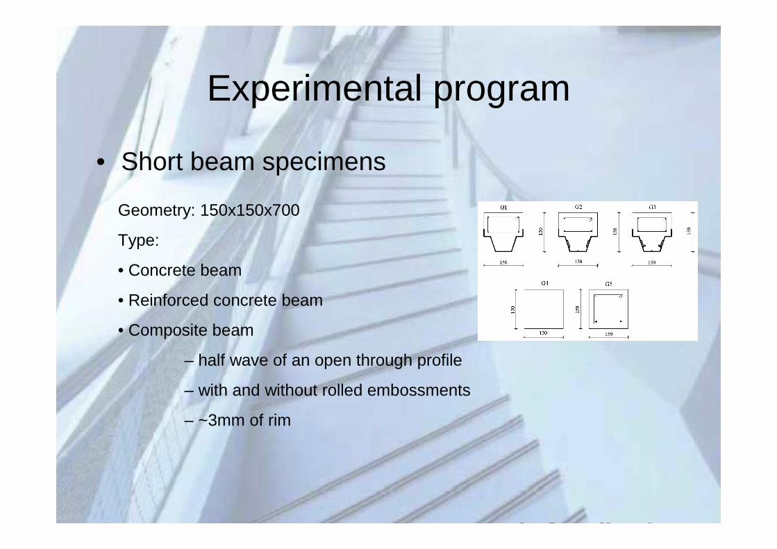
• Short beam specimens
Geometry: 150x150x700
Type:
• Concrete beam
• Reinforced concrete beam
• Composite beam
– half wave of an open through profile
– with and without rolled embossments
– ~3mm of rim
Experimental program
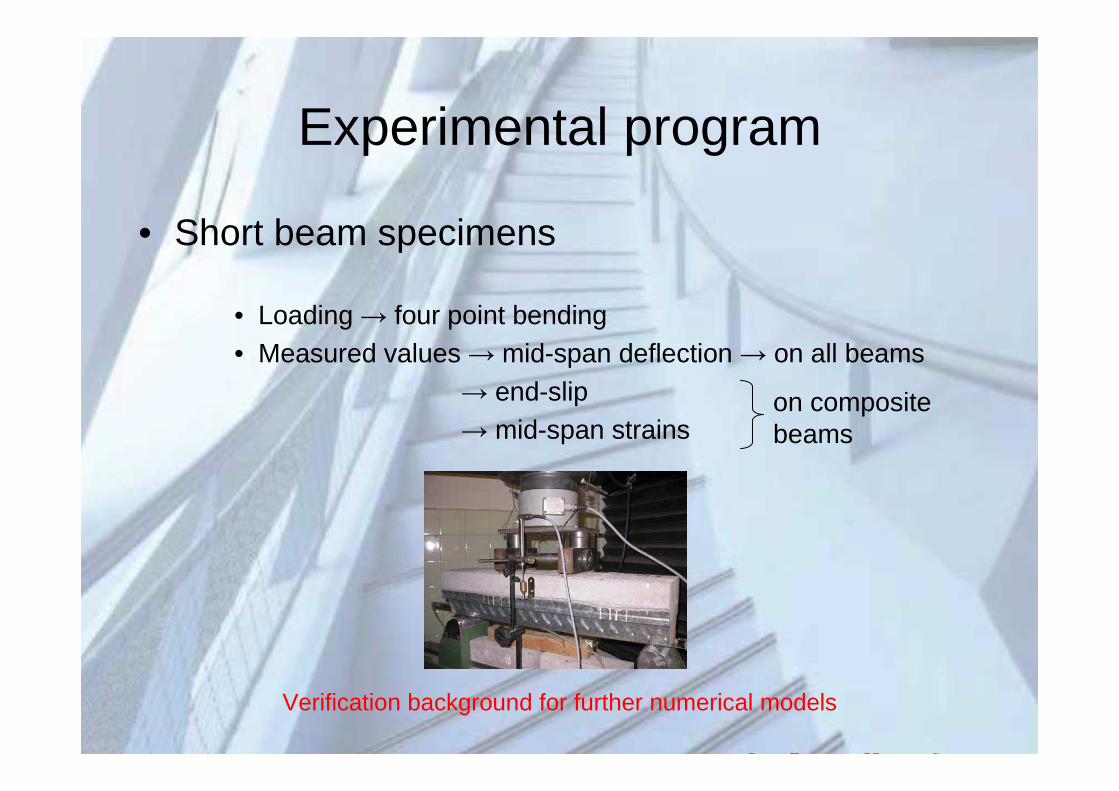
• Short beam specimens
• Loading → four point bending• Measured values → mid-span deflection → on all beams
→ end-slip→ mid-span strains
Verification background for further numerical models
on composite beams
Numerical modelling
• Finite element model development
• 1st concete material model
• 2nd composite connection model
• 3rd composite beam model
ANSYS
Reinforced concrete modelling
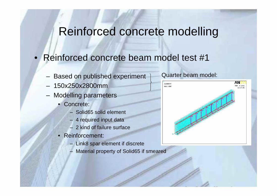
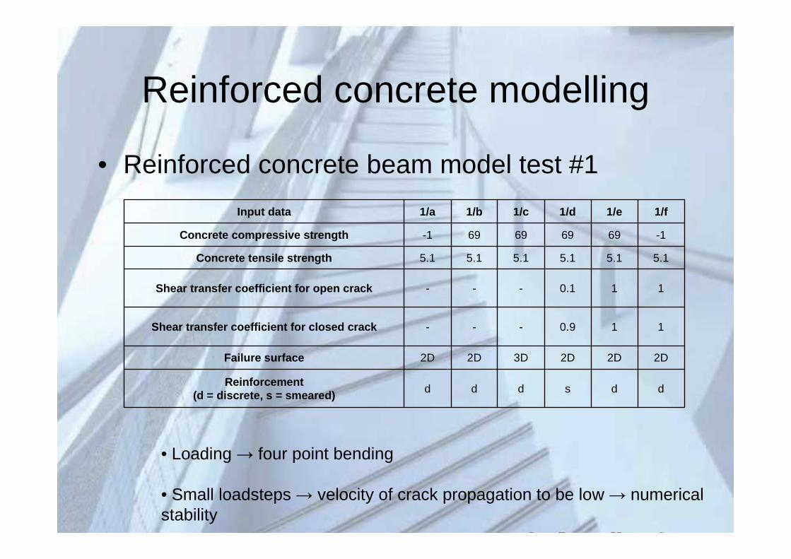
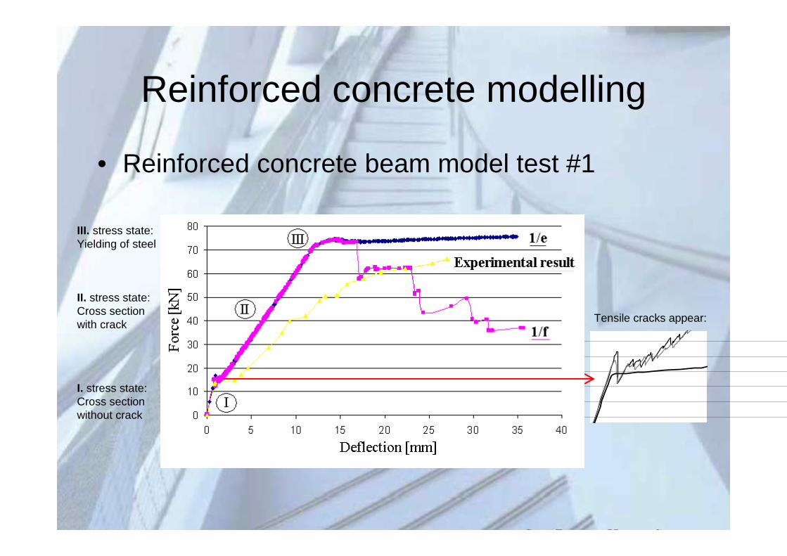
• Reinforced concrete beam model test #1
– Based on published experiment– 150x250x2800mm– Modelling parameters
• Concrete:– Solid65 solid element
– 4 required input data
– 2 kind of failure surface
• Reinforcement:– Link8 spar element if discrete
– Material property of Solid65 if smeared
Quarter beam model:
Reinforced concrete modelling
• Reinforced concrete beam model test #1
ddsdddReinforcement
(d = discrete, s = smeared)
2D2D2D3D2D2DFailure surface
110.9---Shear transfer coefficient for closed crack
110.1---Shear transfer coefficient for open crack
5.15.15.15.15.15.1Concrete tensile strength
-169696969-1Concrete compressive strength
1/f1/e1/d1/c1/b1/aInput data
• Loading → four point bending
• Small loadsteps → velocity of crack propagation to be low → numerical stability
Reinforced concrete modelling
• Reinforced concrete beam model test #1
III. stress state:Yielding of steel
II. stress state: Cross section with crack
I. stress state:Cross section without crack
Tensile cracks appear:
Reinforced concrete modelling
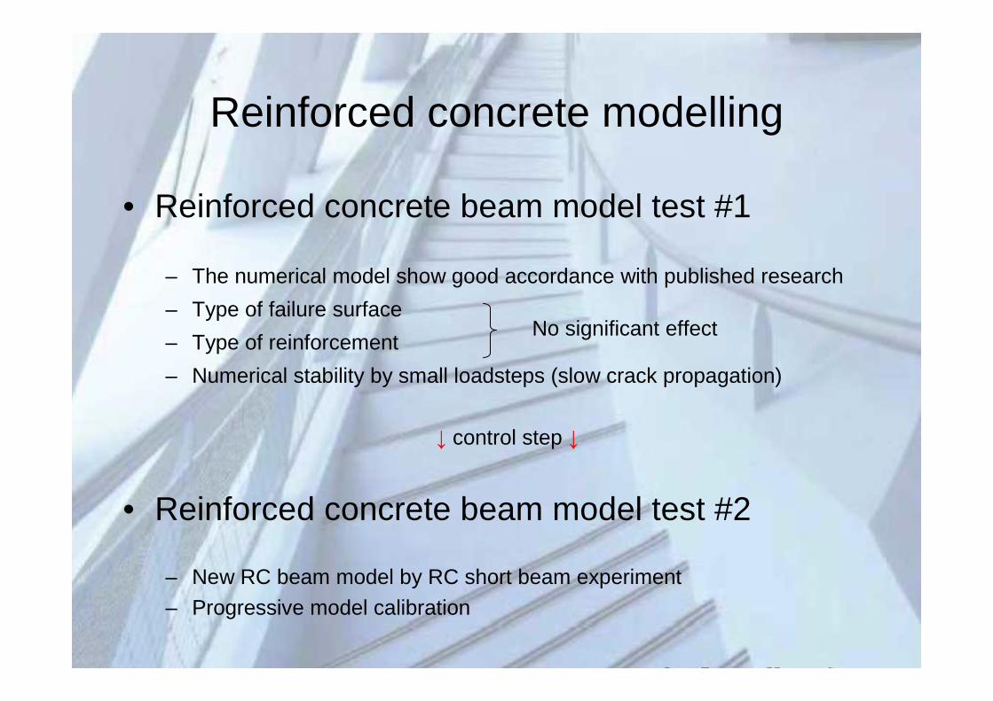
• Reinforced concrete beam model test #1
– The numerical model show good accordance with published research
– Type of failure surface
– Type of reinforcement
– Numerical stability by small loadsteps (slow crack propagation)
↓ control step ↓
• Reinforced concrete beam model test #2
– New RC beam model by RC short beam experiment
– Progressive model calibration
No significant effect
Reinforced concrete modelling
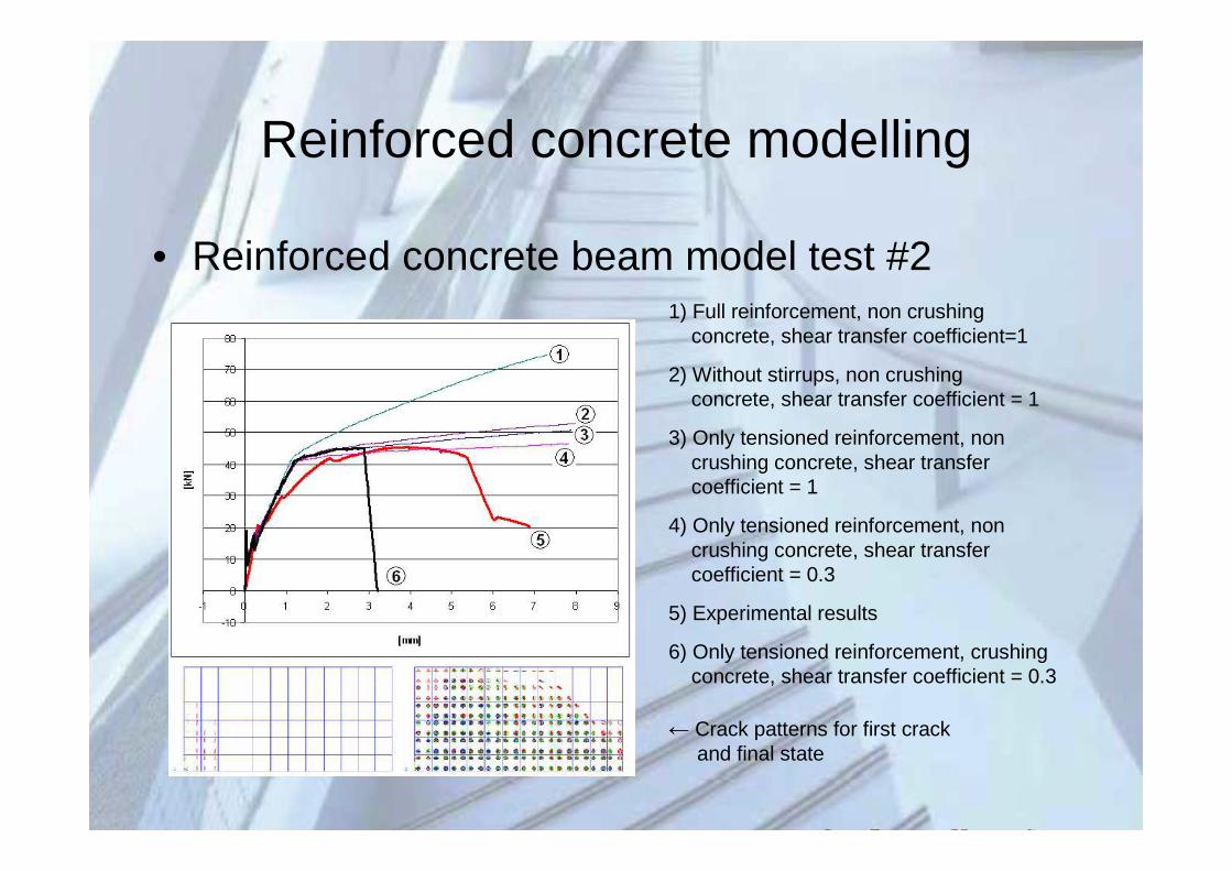
• Reinforced concrete beam model test #21) Full reinforcement, non crushing
concrete, shear transfer coefficient=1
2) Without stirrups, non crushingconcrete, shear transfer coefficient = 1
3) Only tensioned reinforcement, noncrushing concrete, shear transfercoefficient = 1
4) Only tensioned reinforcement, noncrushing concrete, shear transfercoefficient = 0.3
5) Experimental results
6) Only tensioned reinforcement, crushingconcrete, shear transfer coefficient = 0.3
← Crack patterns for first crack and final state
Local models of rolled embossments
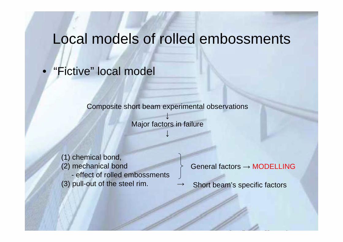
• “Fictive” local model
Composite short beam experimental observations↓
Major factors in failure↓
(1) chemical bond,(2) mechanical bond
- effect of rolled embossments(3) pull-out of the steel rim. →
General factors → MODELLING
Short beam’s specific factors
Local models of rolled embossments
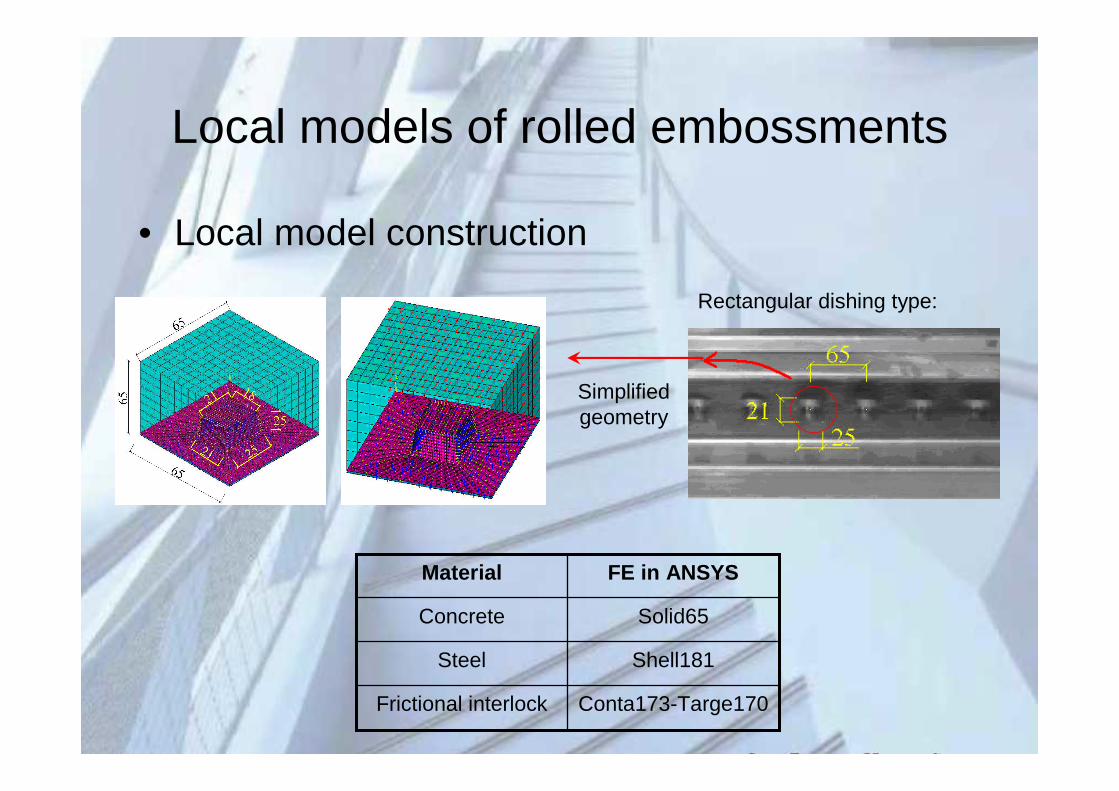
• Local model construction
Conta173-Targe170Frictional interlock
Shell181Steel
Solid65Concrete
FE in ANSYSMaterial
Simplified geometry
Rectangular dishing type:
Local models of rolled embossments
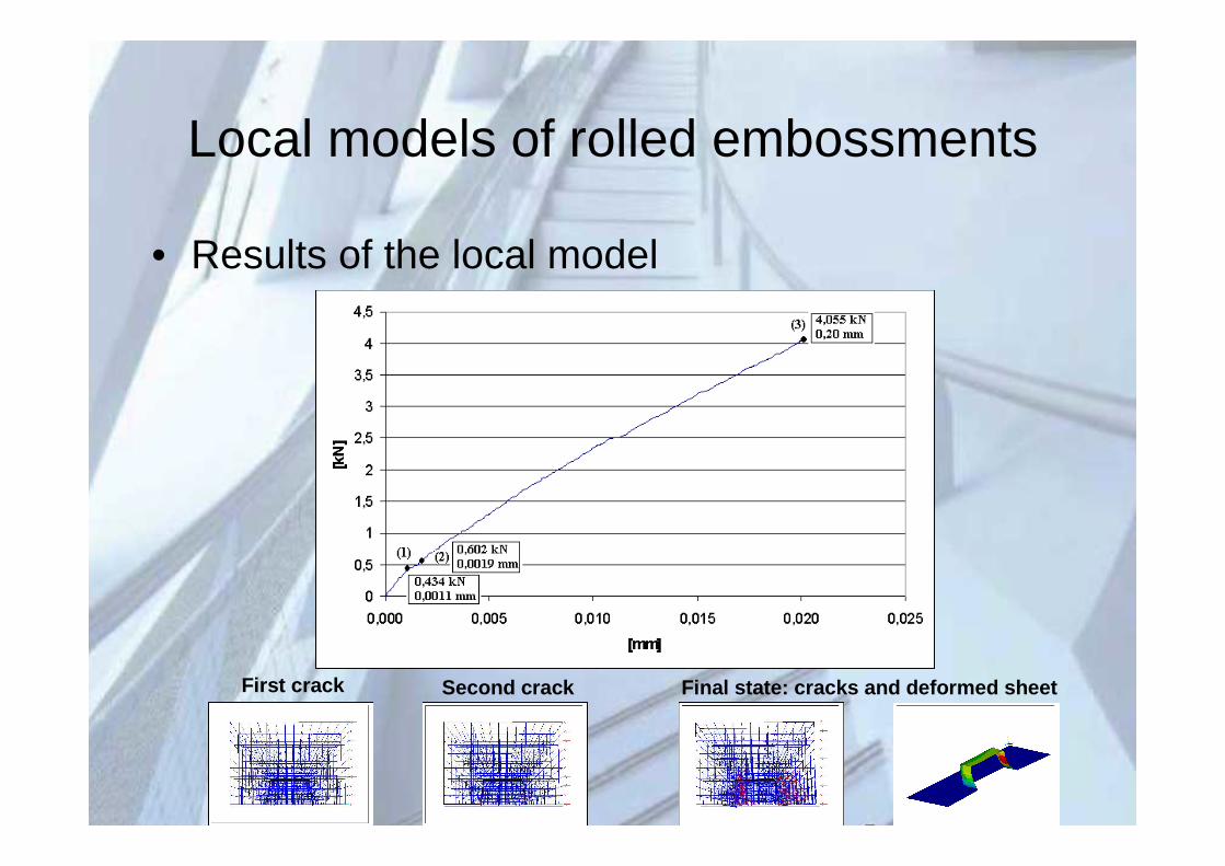
• Results of the local model
First crack Second crack Final state: cracks and deformed sheet
Local models of rolled embossments
• Results of the local model
– Runtime ~5 hours
– Significant increase in runtime when increasing the model size
– Efficient composite beam model
– Embossments spring
– Spring constant local model analysis
Local models of rolled embossments
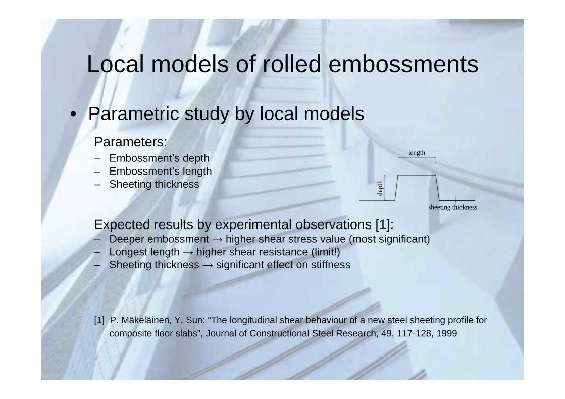
• Parametric study by local modelsParameters:– Embossment’s depth– Embossment’s length– Sheeting thickness
Expected results by experimental observations [1]:– Deeper embossment → higher shear stress value (most significant)– Longest length → higher shear resistance (limit!)– Sheeting thickness → significant effect on stiffness
[1] P. Mäkeläinen, Y. Sun: “The longitudinal shear behaviour of a new steel sheeting profile forcomposite floor slabs”, Journal of Constructional Steel Research, 49, 117-128, 1999
length
dept
h
sheeting thickness
Parametric study by local models
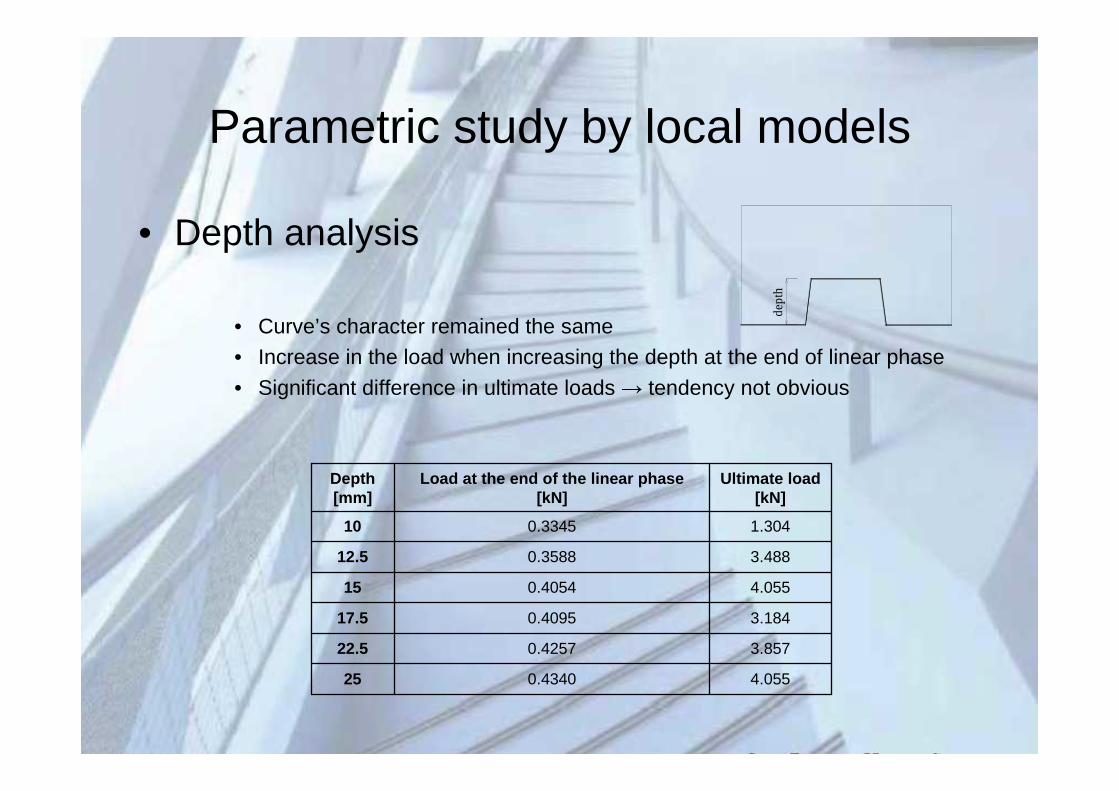
• Depth analysis
• Curve’s character remained the same• Increase in the load when increasing the depth at the end of linear phase
• Significant difference in ultimate loads → tendency not obvious
dept
h
4.0550.434025
3.8570.425722.5
3.1840.409517.5
4.0550.405415
3.4880.358812.5
1.3040.334510
Ultimate load[kN]
Load at the end of the linear phase[kN]
Depth[mm]
Parametric study by local models
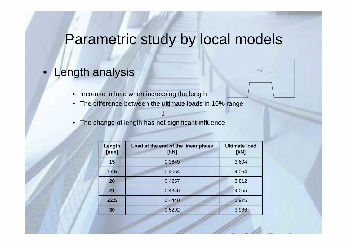
• Length analysis
• Increase in load when increasing the length
• The difference between the ultimate loads in 10% range↓
• The change of length has not significant influence
3.9360.529230
3.9250.444022.5
4.0550.434021
3.8120.425720
4.0540.405417.5
3.6040.364915
Ultimate load[kN]
Load at the end of the linear phase[kN]
Length[mm]
length
Parametric study by local models
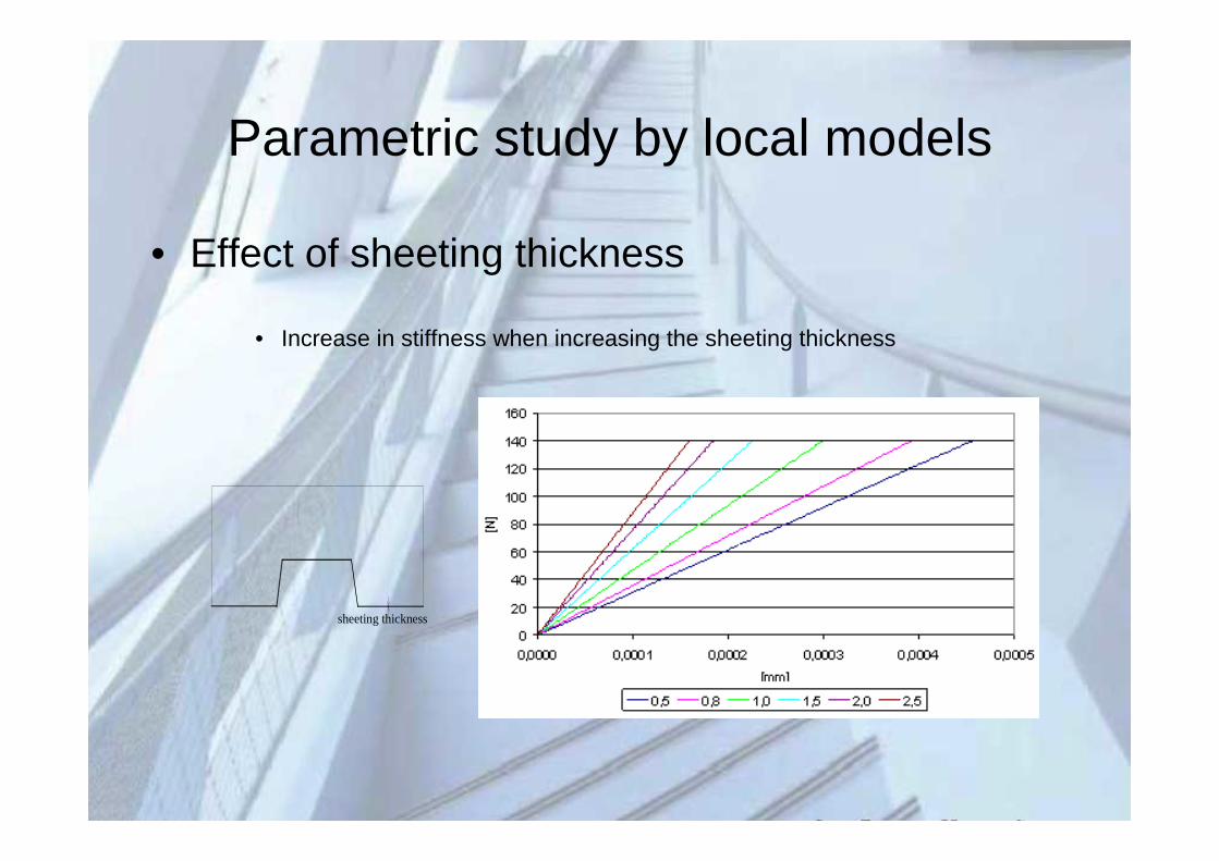
• Effect of sheeting thickness
• Increase in stiffness when increasing the sheeting thickness
sheeting thickness
Concluding remarks
• Novel alternative of experimental analysis (short beam) for composite
connection.
– Tendency of the failure modes became traceable → numerical analysis
• Adequate concrete and reinforced concrete model
• Numerical local model for fictive rolled embossments
– Basic behaviour modes
– Parametric study ↔ published experiments
Contradiction in the results of the depth and length analysis↓
Chosen experiment ↔ traditional push-out tests
Necessity of new laboratory experiments to prove the results↓
Pilot experimental investigation for local model calibration
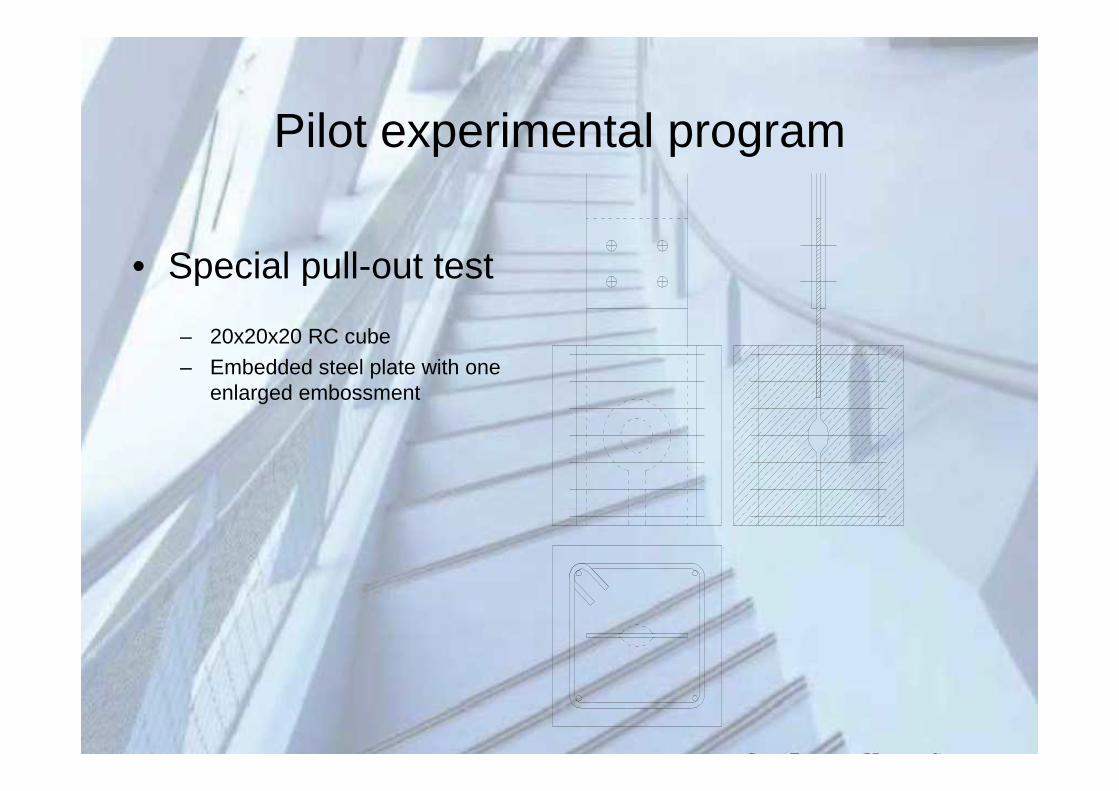
Pilot experimental program
• Special pull-out test
– 20x20x20 RC cube
– Embedded steel plate with oneenlarged embossment

Thank you