Embed Size (px)
Citation preview
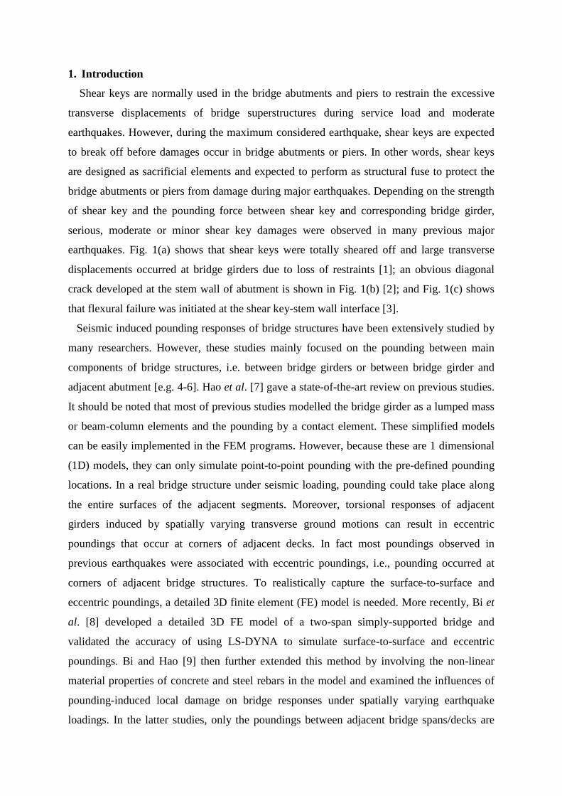
Modelling of shear keys in bridge structures under seismic loads
Kaiming Bi*, Hong Hao
Department of Civil Engineering, Curtin University, Kent Street, Bentley WA 6102
ABSTRACT
Shear keys are used in the bridge abutments and piers to provide transverse restraints for
bridge superstructures. Owing to the relatively small dimensions compared to the main bridge
components (girders, piers, abutments, piles), shear keys are normally regarded as secondary
component of a bridge structure, and their influences on bridge seismic responses are
normally neglected. In reality, shear keys are designed to restrain the lateral displacements of
bridge girders, which will affect the transverse response of the bridge deck, thus influence the
overall structural responses. To study the influences of shear keys on bridge responses to
seismic ground excitations, this paper performs numerical simulations of the seismic
responses of a two-span simply-supported bridge model without or with shear keys in the
abutments and the central pier. A detailed 3D finite element (FE) model is developed by
using the explicit FE code LS-DYNA. The bridge components including bridge girders, piers,
abutments, bearings, shear keys and reinforcement bars are included in the model. The non-
linear material behaviour including the strain rate effects of concrete and steel rebar are
considered. The seismic responses of bridge structures without and with shear keys subjected
to bi-axial spatially varying horizontal ground motions are calculated and compared. The
failure mode and damage mechanism of shear keys are discussed in detail. Numerical results
show that shear keys restrain transverse movements of bridge decks, which influence the
torsional-lateral responses of the decks under bi-axial spatially varying ground excitations;
neglecting shear keys in bridge response analysis may lead to inaccurate predictions of
seismic responses of bridge structures.
Keywords: shear key; 3D model; seismic response; failure mode; damage mechanism.
*Corresponding author, Lecturer, Tel: +61 8 9266 5139; E-mail: [email protected];
Postal address: Room 414, Building 204, Curtin University, Kent Street, Bentley WA 6102
1. Introduction
Shear keys are normally used in the bridge abutments and piers to restrain the excessive
transverse displacements of bridge superstructures during service load and moderate
earthquakes. However, during the maximum considered earthquake, shear keys are expected
to break off before damages occur in bridge abutments or piers. In other words, shear keys
are designed as sacrificial elements and expected to perform as structural fuse to protect the
bridge abutments or piers from damage during major earthquakes. Depending on the strength
of shear key and the pounding force between shear key and corresponding bridge girder,
serious, moderate or minor shear key damages were observed in many previous major
earthquakes. Fig. 1(a) shows that shear keys were totally sheared off and large transverse
displacements occurred at bridge girders due to loss of restraints [1]; an obvious diagonal
crack developed at the stem wall of abutment is shown in Fig. 1(b) [2]; and Fig. 1(c) shows
that flexural failure was initiated at the shear key-stem wall interface [3].
Seismic induced pounding responses of bridge structures have been extensively studied by
many researchers. However, these studies mainly focused on the pounding between main
components of bridge structures, i.e. between bridge girders or between bridge girder and
adjacent abutment [e.g. 4-6]. Hao et al. [7] gave a state-of-the-art review on previous studies.
It should be noted that most of previous studies modelled the bridge girder as a lumped mass
or beam-column elements and the pounding by a contact element. These simplified models
can be easily implemented in the FEM programs. However, because these are 1 dimensional
(1D) models, they can only simulate point-to-point pounding with the pre-defined pounding
locations. In a real bridge structure under seismic loading, pounding could take place along
the entire surfaces of the adjacent segments. Moreover, torsional responses of adjacent
girders induced by spatially varying transverse ground motions can result in eccentric
poundings that occur at corners of adjacent decks. In fact most poundings observed in
previous earthquakes were associated with eccentric poundings, i.e., pounding occurred at
corners of adjacent bridge structures. To realistically capture the surface-to-surface and
eccentric poundings, a detailed 3D finite element (FE) model is needed. More recently, Bi et
al. [8] developed a detailed 3D FE model of a two-span simply-supported bridge and
validated the accuracy of using LS-DYNA to simulate surface-to-surface and eccentric
poundings. Bi and Hao [9] then further extended this method by involving the non-linear
material properties of concrete and steel rebars in the model and examined the influences of
pounding-induced local damage on bridge responses under spatially varying earthquake
loadings. In the latter studies, only the poundings between adjacent bridge spans/decks are
considered. Although shear key damages due to deck pounding have been observed in many
previous earthquakes, none of these studies considered the shear keys and their influences on
overall bridge responses. This paper extends the previous studies [8, 9] on detailed modelling
of pounding damages between adjacent bridge spans to bi-axial spatially varying horizontal
ground motions by including shear keys in the model. The poundings between shear keys and
bridge decks are modelled and examined in detail. Since pounding between deck and shear
key prevents excessive transverse movements of the deck and absorbs a large amount of
energy, it may significantly affect the overall bridge structural responses. Therefore the
influence of including shear keys in the analysis of bridge responses is also investigated and
discussed in the present paper.
Limited research is available in the literature on the seismic performance of bridge shear
keys. Bozorgzadeh et al. [10, 11] carried out experimental studies to assess the shear strength
and failure mode of exterior shear keys in bridge abutments under transverse forces. Two
kinds of failure mechanism, i.e. sliding shear failure and diagonal shear failure, were
identified for exterior shear keys. Silva et al. performed experimental and analytical
investigations to evaluate the seismic performance of sacrificial interior [13] and exterior [14]
shear keys. Rational models of the force and deformation capacity of shear keys as well as
their postpeak performance under cyclic loads were proposed based on the experimental data.
Maleki investigated the seismic performance of ordinary [15] and skewed [16] bridges with
retainers placed on each side of elastomeric bearings. Design recommendations were
proposed for bridges with such retainers. Goel and Chopra [17] examined the role of shear
keys at bridge abutments on the seismic behaviour of ordinary bridges crossing fault-rupture
zones. Three different shear key conditions, i.e. nonlinear, linear and no shear keys, were
examined. Numerical results show that seismic demands for a bridge with nonlinear shear
keys can generally be bounded by the demands of a bridge with elastic shear keys and a
bridge with no shear keys.
It can be seen that previous studies on the shear key mainly focused on its shear strength.
The investigation of the influence of shear keys on the whole bridge responses, i.e.,
restraining the transverse deck movement which may influence the overall bridge responses
because of the restrained torsional responses of the deck, were relatively less. Moreover, all
these studies [15-17] used the simplified spring-dashpot elements to model the pounding
between shear key and bridge girder/bearing, indicating only point-to-point pounding by
assuming uniform contact between deck and shear key was considered. In reality, spatially
varying earthquake ground motions always induce torsional responses on even a perfectly
symmetric bridge deck, which usually cause eccentric pounding between bridge deck and
shear key, as observed in many earthquakes, e.g. Fig 1(c). Thus it is important to develop a
detailed 3D model that can simulate the surface-to-surface and eccentric poundings for more
realistic predictions of interactions between bridge superstructures and shear keys.
In this study a two-span simply-supported bridge located at a canyon site is selected as an
example to investigate the seismic induced poundings between bridge decks and shear keys
and their influences on the overall bridge responses. This work is an extension of the authors’
previous work [9]. The primary differences between the current study and the previous work
include: (1) Detailed 3D models of shear keys are included in the numerical simulation; (2)
Poundings between shear keys and bridge girders are examined in detail; (3) The influence of
shear keys on overall bridge responses are discussed; (4) The failure mode and damage
mechanism of shear keys due to pounding with bridge decks are examined.
Many previous studies (e.g. [18, 19]) revealed that soil-structure interaction (SSI) can
further alter the bridge responses under earthquake loadings. Not to further complicate the
problem, SSI is, however, not considered in the present study since the primary aim of this
study is to investigate the influence of shear keys on the seismic induced pounding responses
of bridge structures. It is believed that the general observations made in this study regarding
the influence of shear keys on the seismic responses of bridge structures will not be changed
although SSI is not considered. In fact, this is not an uncommon practice in studying the
pounding responses of engineering structures subjected to earthquake loadings, e.g. Refs [4, 5,
20-23] among many others did not consider the influence of SSI.
2. Finite element model
2.1 Bridge details
Fig. 2 shows the elevation view of a two-span simply-supported bridge located at a canyon
site. The length of each box girder as shown in Fig. 3(a) is 30 m. To allow for contraction and
expansion of bridge girders from creep, shrinkage, temperature fluctuation and traffic without
generating constraint forces in the structure, a 60 mm gap is introduced between the abutment
and the bridge girder and between the adjacent girders. The cross section at the central pier is
shown in Fig. 3(b). The pier foundation is a strip footing with the dimension of 6 ×4 ×1.8 m.
The height of the two-square-column central pier is 9 m, and the length and width are 1.2 m
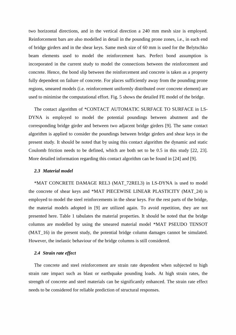
respectively. Fig. 3(c) shows the cross section of the bridge column. The longitudinal steel
reinforcements with a diameter of 30 mm are spaced at 180 mm on the four sizes of the pier.
The stirrups of diameter 20 mm are spaced at 200 mm along the pier height. Each column has
a reinforcement cover depth of 60 mm. Two L-shaped gravity abutments are used to support
the bridge at the two ends with cross section shown in Fig. 3(d). To restrain excessive lateral
displacement during service and earthquake loads, one shear key is introduced at each side of
the pier bent and abutments. The height of the shear keys is 0.48 m and the thickness is 0.24
m. The widths are 0.96 and 1.56 m for shear keys at abutments and central pier respectively.
The gap between shear key and corresponding bridge girder is 60 mm as shown in Fig. 3. The
steel reinforcements, with diameters of 20 and 16 mm, are spaced at 120 and 180 mm for the
primary reinforcements and stirrups respectively in the bridge girder. The reinforcement bars
in the shear keys at abutments and central pier are shown in Figs. 4(a) and (b). The diameters
of the vertical and horizontal bars are 14 and 10 mm respectively.
The two bridge girders are supported by eight neoprene bearing pads. The widths of the
pad in the longitudinal (x) and transverse (z) directions are 0.36 and 0.48 m respectively, and
the thickness is 0.06 m. The bridge is located on a canyon site, consisting of horizontally
extended soil layers on a half-space (base rock) as shown in Fig. 2. Points A, B and C are the
three bridge support locations on the ground surface. The corresponding points on the base
rock are A’, B’ and C’. The soil depths for the three sites are 42, 33 and 42 m respectively.
As mentioned above, the abutment and pier foundations are assumed rigidly fixed to the
ground without considering SSI so as to focus primarily on the influence of shear keys on the
seismic induced pounding responses of the bridge.
2.2 Element and contact
Explicit FE code LS-DYNA [24] is employed to calculate the seismic responses of the
bridge. Constant stress solid elements are employed for all concrete members in this study. A
previous study [9] found that a 60 mm mesh size can yield a good balance between the
computational time and accuracy of results. The mesh size of 60 mm is therefore adopted in
the present study to mesh the pounding prone areas. In particular, detailed modelling is
applied to a length of 0.18 m from the backwall of the abutment, to 0.96 m from each end of
bridge girders and to all the shear keys. Beyond these regions, the mesh size in the
longitudinal direction is 0.3 m for the abutments and bridge girders. The bridge bent is also
meshed with a fine mesh size of 60 mm. For the pier, a mesh size of 60 mm is applied in the
two horizontal directions, and in the vertical direction a 240 mm mesh size is employed.
Reinforcement bars are also modelled in detail in the pounding prone zones, i.e., in each end
of bridge girders and in the shear keys. Same mesh size of 60 mm is used for the Belytschko
beam elements used to model the reinforcement bars. Perfect bond assumption is
incorporated in the current study to model the connections between the reinforcement and
concrete. Hence, the bond slip between the reinforcement and concrete is taken as a property
fully dependent on failure of concrete. For places sufficiently away from the pounding prone
regions, smeared models (i.e. reinforcement uniformly distributed over concrete element) are
used to minimise the computational effort. Fig. 5 shows the detailed FE model of the bridge.
The contact algorithm of *CONTACT AUTOMATIC SURFACE TO SURFACE in LS-
DYNA is employed to model the potential poundings between abutment and the
corresponding bridge girder and between two adjacent bridge girders [9]. The same contact
algorithm is applied to consider the poundings between bridge girders and shear keys in the
present study. It should be noted that by using this contact algorithm the dynamic and static
Coulomb friction needs to be defined, which are both set to be 0.5 in this study [22, 23].
More detailed information regarding this contact algorithm can be found in [24] and [9].
2.3 Material model
*MAT CONCRETE DAMAGE REL3 (MAT_72REL3) in LS-DYNA is used to model
the concrete of shear keys and *MAT PIECEWISE LINEAR PLASTICITY (MAT_24) is
employed to model the steel reinforcements in the shear keys. For the rest parts of the bridge,
the material models adopted in [9] are utilized again. To avoid repetition, they are not
presented here. Table 1 tabulates the material properties. It should be noted that the bridge
columns are modelled by using the smeared material model *MAT PSEUDO TENSOT
(MAT_16) in the present study, the potential bridge column damages cannot be simulated.
However, the inelastic behaviour of the bridge columns is still considered.
2.4 Strain rate effect
The concrete and steel reinforcement are strain rate dependent when subjected to high
strain rate impact such as blast or earthquake pounding loads. At high strain rates, the
strength of concrete and steel materials can be significantly enhanced. The strain rate effect
needs to be considered for reliable prediction of structural responses.
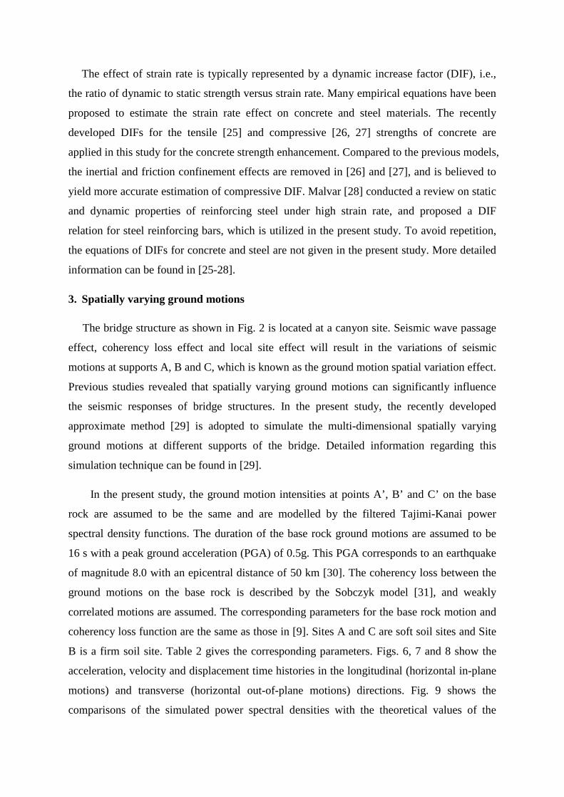
The effect of strain rate is typically represented by a dynamic increase factor (DIF), i.e.,
the ratio of dynamic to static strength versus strain rate. Many empirical equations have been
proposed to estimate the strain rate effect on concrete and steel materials. The recently
developed DIFs for the tensile [25] and compressive [26, 27] strengths of concrete are
applied in this study for the concrete strength enhancement. Compared to the previous models,
the inertial and friction confinement effects are removed in [26] and [27], and is believed to
yield more accurate estimation of compressive DIF. Malvar [28] conducted a review on static
and dynamic properties of reinforcing steel under high strain rate, and proposed a DIF
relation for steel reinforcing bars, which is utilized in the present study. To avoid repetition,
the equations of DIFs for concrete and steel are not given in the present study. More detailed
information can be found in [25-28].
3. Spatially varying ground motions
The bridge structure as shown in Fig. 2 is located at a canyon site. Seismic wave passage
effect, coherency loss effect and local site effect will result in the variations of seismic
motions at supports A, B and C, which is known as the ground motion spatial variation effect.
Previous studies revealed that spatially varying ground motions can significantly influence
the seismic responses of bridge structures. In the present study, the recently developed
approximate method [29] is adopted to simulate the multi-dimensional spatially varying
ground motions at different supports of the bridge. Detailed information regarding this
simulation technique can be found in [29].
In the present study, the ground motion intensities at points A’, B’ and C’ on the base
rock are assumed to be the same and are modelled by the filtered Tajimi-Kanai power
spectral density functions. The duration of the base rock ground motions are assumed to be
16 s with a peak ground acceleration (PGA) of 0.5g. This PGA corresponds to an earthquake
of magnitude 8.0 with an epicentral distance of 50 km [30]. The coherency loss between the
ground motions on the base rock is described by the Sobczyk model [31], and weakly
correlated motions are assumed. The corresponding parameters for the base rock motion and
coherency loss function are the same as those in [9]. Sites A and C are soft soil sites and Site
B is a firm soil site. Table 2 gives the corresponding parameters. Figs. 6, 7 and 8 show the
acceleration, velocity and displacement time histories in the longitudinal (horizontal in-plane
motions) and transverse (horizontal out-of-plane motions) directions. Fig. 9 shows the
comparisons of the simulated power spectral densities with the theoretical values of the
longitudinal motions, good agreements are observed. For conciseness, the comparisons of the
transverse motions are not plotted, good agreements are also observed. The vertical motion is
not included in the analysis, because: (1) The primary aim of this study is to investigate the
transverse restraining effect provided by the shear keys; (2) For the far-field earthquake as
considered in the present study, the vertical component is usually smaller than the horizontal
components; (3) For the bridge as shown in Fig. 2, the first vertical vibration mode is the
seventh mode based on an eigenvalue analysis, the contribution of vertical component on the
horizontal and transverse structural responses is believed insignificant. However, it should be
noted that if the bridge is subjected to a near-fault earthquake, the contribution of the vertical
component might be evident and it might be necessary to consider the influence of vertical
earthquake loading on the bridge seismic responses.
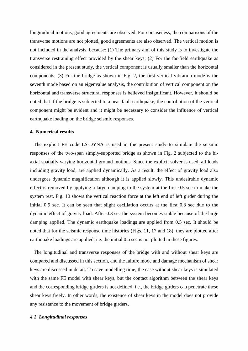
4. Numerical results
The explicit FE code LS-DYNA is used in the present study to simulate the seismic
responses of the two-span simply-supported bridge as shown in Fig. 2 subjected to the bi-
axial spatially varying horizontal ground motions. Since the explicit solver is used, all loads
including gravity load, are applied dynamically. As a result, the effect of gravity load also
undergoes dynamic magnification although it is applied slowly. This undesirable dynamic
effect is removed by applying a large damping to the system at the first 0.5 sec to make the
system rest. Fig. 10 shows the vertical reaction force at the left end of left girder during the
initial 0.5 sec. It can be seen that slight oscillation occurs at the first 0.3 sec due to the
dynamic effect of gravity load. After 0.3 sec the system becomes stable because of the large
damping applied. The dynamic earthquake loadings are applied from 0.5 sec. It should be
noted that for the seismic response time histories (Figs. 11, 17 and 18), they are plotted after
earthquake loadings are applied, i.e. the initial 0.5 sec is not plotted in these figures.
The longitudinal and transverse responses of the bridge with and without shear keys are
compared and discussed in this section, and the failure mode and damage mechanism of shear
keys are discussed in detail. To save modelling time, the case without shear keys is simulated
with the same FE model with shear keys, but the contact algorithm between the shear keys
and the corresponding bridge girders is not defined, i.e., the bridge girders can penetrate these
shear keys freely. In other words, the existence of shear keys in the model does not provide
any resistance to the movement of bridge girders.
4.1 Longitudinal responses
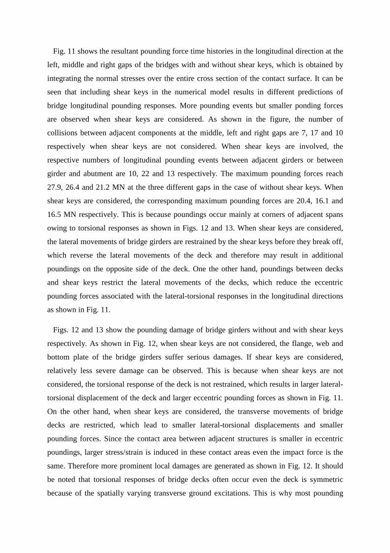
Fig. 11 shows the resultant pounding force time histories in the longitudinal direction at the
left, middle and right gaps of the bridges with and without shear keys, which is obtained by
integrating the normal stresses over the entire cross section of the contact surface. It can be
seen that including shear keys in the numerical model results in different predictions of
bridge longitudinal pounding responses. More pounding events but smaller ponding forces
are observed when shear keys are considered. As shown in the figure, the number of
collisions between adjacent components at the middle, left and right gaps are 7, 17 and 10
respectively when shear keys are not considered. When shear keys are involved, the
respective numbers of longitudinal pounding events between adjacent girders or between
girder and abutment are 10, 22 and 13 respectively. The maximum pounding forces reach
27.9, 26.4 and 21.2 MN at the three different gaps in the case of without shear keys. When
shear keys are considered, the corresponding maximum pounding forces are 20.4, 16.1 and
16.5 MN respectively. This is because poundings occur mainly at corners of adjacent spans
owing to torsional responses as shown in Figs. 12 and 13. When shear keys are considered,
the lateral movements of bridge girders are restrained by the shear keys before they break off,
which reverse the lateral movements of the deck and therefore may result in additional
poundings on the opposite side of the deck. One the other hand, poundings between decks
and shear keys restrict the lateral movements of the decks, which reduce the eccentric
pounding forces associated with the lateral-torsional responses in the longitudinal directions
as shown in Fig. 11.
Figs. 12 and 13 show the pounding damage of bridge girders without and with shear keys
respectively. As shown in Fig. 12, when shear keys are not considered, the flange, web and
bottom plate of the bridge girders suffer serious damages. If shear keys are considered,
relatively less severe damage can be observed. This is because when shear keys are not
considered, the torsional response of the deck is not restrained, which results in larger lateral-
torsional displacement of the deck and larger eccentric pounding forces as shown in Fig. 11.
On the other hand, when shear keys are considered, the transverse movements of bridge
decks are restricted, which lead to smaller lateral-torsional displacements and smaller
pounding forces. Since the contact area between adjacent structures is smaller in eccentric
poundings, larger stress/strain is induced in these contact areas even the impact force is the
same. Therefore more prominent local damages are generated as shown in Fig. 12. It should
be noted that torsional responses of bridge decks often occur even the deck is symmetric
because of the spatially varying transverse ground excitations. This is why most pounding
damages between adjacent bridge spans observed in previous earthquakes are associated to
eccentric poundings.
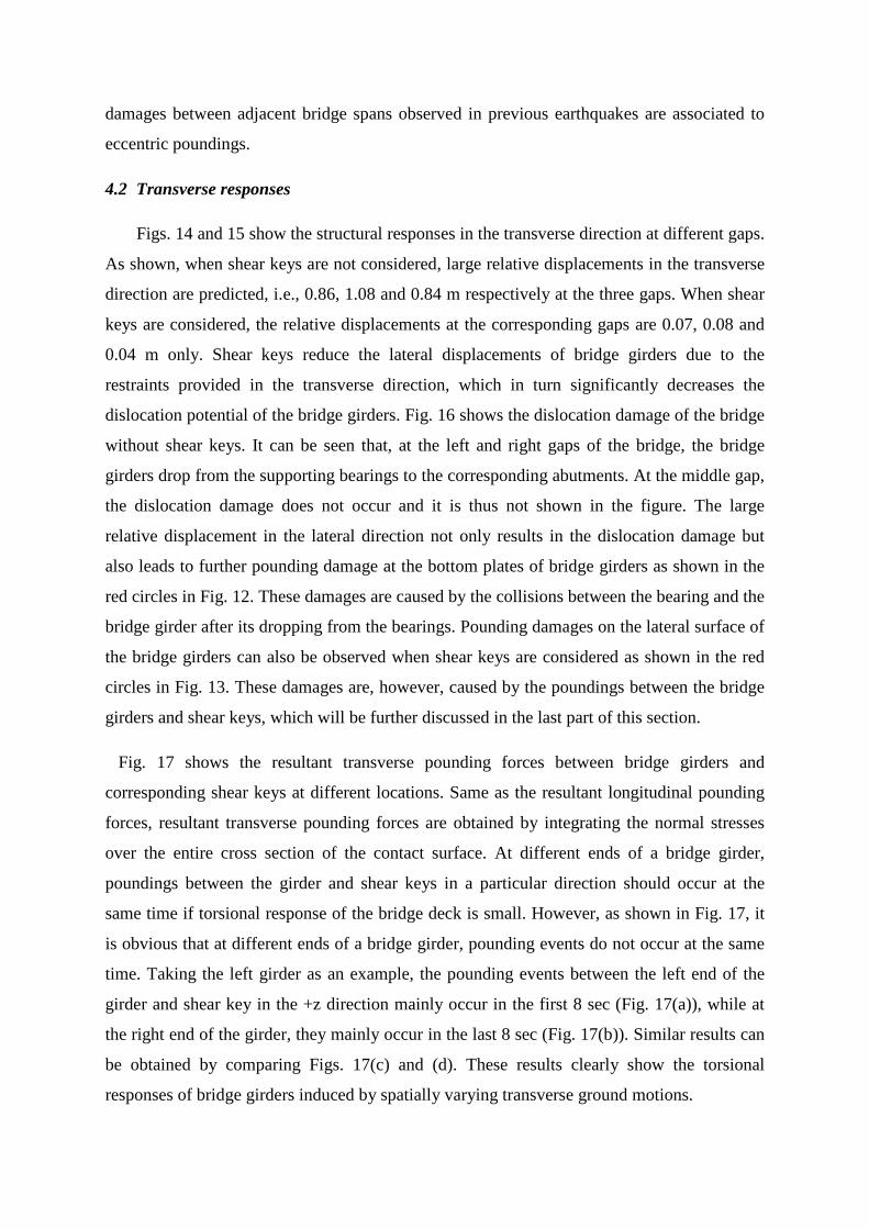
4.2 Transverse responses
Figs. 14 and 15 show the structural responses in the transverse direction at different gaps.
As shown, when shear keys are not considered, large relative displacements in the transverse
direction are predicted, i.e., 0.86, 1.08 and 0.84 m respectively at the three gaps. When shear
keys are considered, the relative displacements at the corresponding gaps are 0.07, 0.08 and
0.04 m only. Shear keys reduce the lateral displacements of bridge girders due to the
restraints provided in the transverse direction, which in turn significantly decreases the
dislocation potential of the bridge girders. Fig. 16 shows the dislocation damage of the bridge
without shear keys. It can be seen that, at the left and right gaps of the bridge, the bridge
girders drop from the supporting bearings to the corresponding abutments. At the middle gap,
the dislocation damage does not occur and it is thus not shown in the figure. The large
relative displacement in the lateral direction not only results in the dislocation damage but
also leads to further pounding damage at the bottom plates of bridge girders as shown in the
red circles in Fig. 12. These damages are caused by the collisions between the bearing and the
bridge girder after its dropping from the bearings. Pounding damages on the lateral surface of
the bridge girders can also be observed when shear keys are considered as shown in the red
circles in Fig. 13. These damages are, however, caused by the poundings between the bridge
girders and shear keys, which will be further discussed in the last part of this section.
Fig. 17 shows the resultant transverse pounding forces between bridge girders and
corresponding shear keys at different locations. Same as the resultant longitudinal pounding
forces, resultant transverse pounding forces are obtained by integrating the normal stresses
over the entire cross section of the contact surface. At different ends of a bridge girder,
poundings between the girder and shear keys in a particular direction should occur at the
same time if torsional response of the bridge deck is small. However, as shown in Fig. 17, it
is obvious that at different ends of a bridge girder, pounding events do not occur at the same
time. Taking the left girder as an example, the pounding events between the left end of the
girder and shear key in the +z direction mainly occur in the first 8 sec (Fig. 17(a)), while at
the right end of the girder, they mainly occur in the last 8 sec (Fig. 17(b)). Similar results can
be obtained by comparing Figs. 17(c) and (d). These results clearly show the torsional
responses of bridge girders induced by spatially varying transverse ground motions.
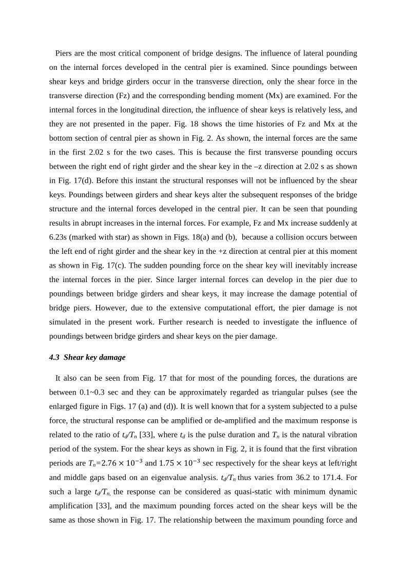
Piers are the most critical component of bridge designs. The influence of lateral pounding
on the internal forces developed in the central pier is examined. Since poundings between
shear keys and bridge girders occur in the transverse direction, only the shear force in the
transverse direction (Fz) and the corresponding bending moment (Mx) are examined. For the
internal forces in the longitudinal direction, the influence of shear keys is relatively less, and
they are not presented in the paper. Fig. 18 shows the time histories of Fz and Mx at the
bottom section of central pier as shown in Fig. 2. As shown, the internal forces are the same
in the first 2.02 s for the two cases. This is because the first transverse pounding occurs
between the right end of right girder and the shear key in the –z direction at 2.02 s as shown
in Fig. 17(d). Before this instant the structural responses will not be influenced by the shear
keys. Poundings between girders and shear keys alter the subsequent responses of the bridge
structure and the internal forces developed in the central pier. It can be seen that pounding
results in abrupt increases in the internal forces. For example, Fz and Mx increase suddenly at
6.23s (marked with star) as shown in Figs. 18(a) and (b), because a collision occurs between
the left end of right girder and the shear key in the +z direction at central pier at this moment
as shown in Fig. 17(c). The sudden pounding force on the shear key will inevitably increase
the internal forces in the pier. Since larger internal forces can develop in the pier due to
poundings between bridge girders and shear keys, it may increase the damage potential of
bridge piers. However, due to the extensive computational effort, the pier damage is not
simulated in the present work. Further research is needed to investigate the influence of
poundings between bridge girders and shear keys on the pier damage.
4.3 Shear key damage
It also can be seen from Fig. 17 that for most of the pounding forces, the durations are
between 0.1~0.3 sec and they can be approximately regarded as triangular pulses (see the
enlarged figure in Figs. 17 (a) and (d)). It is well known that for a system subjected to a pulse
force, the structural response can be amplified or de-amplified and the maximum response is
related to the ratio of td/Tn [33], where td is the pulse duration and Tn is the natural vibration
period of the system. For the shear keys as shown in Fig. 2, it is found that the first vibration
periods are Tn=2.76 × 10⁻³ and 1.75 × 10⁻³ sec respectively for the shear keys at left/right
and middle gaps based on an eigenvalue analysis. td/Tn thus varies from 36.2 to 171.4. For
such a large td/Tn, the response can be considered as quasi-static with minimum dynamic
amplification [33], and the maximum pounding forces acted on the shear keys will be the
same as those shown in Fig. 17. The relationship between the maximum pounding force and
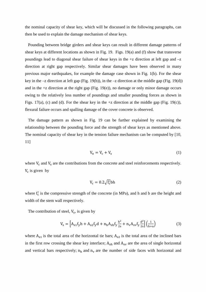
the nominal capacity of shear key, which will be discussed in the following paragraphs, can
then be used to explain the damage mechanism of shear keys.
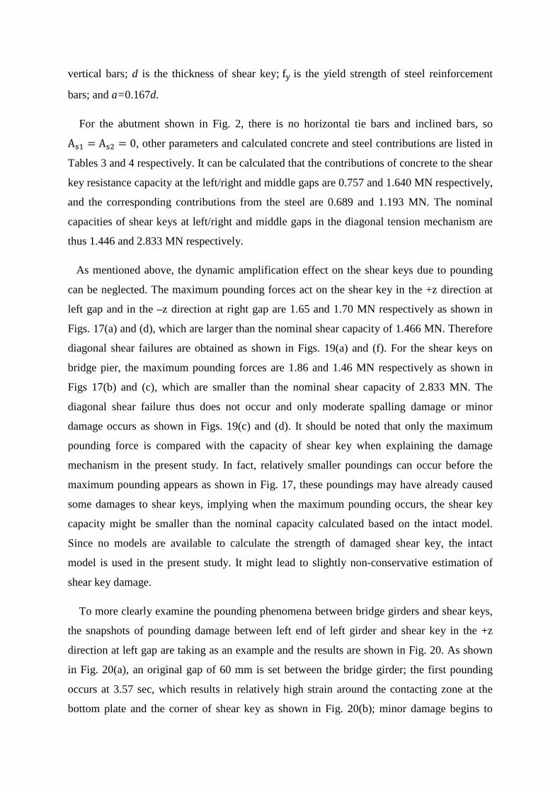
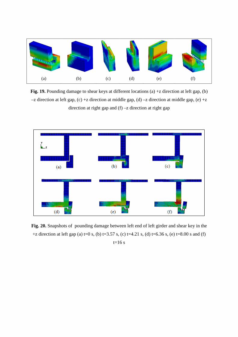
Pounding between bridge girders and shear keys can result in different damage patterns of
shear keys at different locations as shown in Fig. 19. Figs. 19(a) and (f) show that transverse
poundings lead to diagonal shear failure of shear keys in the +z direction at left gap and –z
direction at right gap respectively. Similar shear damages have been observed in many
previous major earthquakes, for example the damage case shown in Fig. 1(b). For the shear
key in the –z direction at left gap (Fig. 19(b)), in the –z direction at the middle gap (Fig. 19(d))
and in the +z direction at the right gap (Fig. 19(e)), no damage or only minor damage occurs
owing to the relatively less number of poundings and smaller pounding forces as shown in
Figs. 17(a), (c) and (d). For the shear key in the +z direction at the middle gap (Fig. 19(c)),
flexural failure occurs and spalling damage of the cover concrete is observed.
The damage pattern as shown in Fig. 19 can be further explained by examining the
relationship between the pounding force and the strength of shear keys as mentioned above.
The nominal capacity of shear key in the tension failure mechanism can be computed by [10,
11]
Vn = Vc + Vs (1)
where Vc and Vs are the contributions from the concrete and steel reinforcements respectively.
Vc is given by
Vc = 0.2�fc′bh (2)
where fc′ is the compressive strength of the concrete (in MPa), and h and b are the height and
width of the stem wall respectively.
The contribution of steel, Vs, is given by
Vs = �As1fyh + As2fyd + nhAshfyh2
2s+ nvAsvfy
d2
2s� � 1
h+a� (3)
where As1 is the total area of the horizontal tie bars; As2 is the total area of the inclined bars
in the first row crossing the shear key interface; Ash and Asv are the area of single horizontal
and vertical bars respectively; nh and nv are the number of side faces with horizontal and
vertical bars; d is the thickness of shear key; fy is the yield strength of steel reinforcement
bars; and a=0.167d.
For the abutment shown in Fig. 2, there is no horizontal tie bars and inclined bars, so
As1 = As2 = 0, other parameters and calculated concrete and steel contributions are listed in
Tables 3 and 4 respectively. It can be calculated that the contributions of concrete to the shear
key resistance capacity at the left/right and middle gaps are 0.757 and 1.640 MN respectively,
and the corresponding contributions from the steel are 0.689 and 1.193 MN. The nominal
capacities of shear keys at left/right and middle gaps in the diagonal tension mechanism are
thus 1.446 and 2.833 MN respectively.
As mentioned above, the dynamic amplification effect on the shear keys due to pounding
can be neglected. The maximum pounding forces act on the shear key in the +z direction at
left gap and in the –z direction at right gap are 1.65 and 1.70 MN respectively as shown in
Figs. 17(a) and (d), which are larger than the nominal shear capacity of 1.466 MN. Therefore
diagonal shear failures are obtained as shown in Figs. 19(a) and (f). For the shear keys on
bridge pier, the maximum pounding forces are 1.86 and 1.46 MN respectively as shown in
Figs 17(b) and (c), which are smaller than the nominal shear capacity of 2.833 MN. The
diagonal shear failure thus does not occur and only moderate spalling damage or minor
damage occurs as shown in Figs. 19(c) and (d). It should be noted that only the maximum
pounding force is compared with the capacity of shear key when explaining the damage
mechanism in the present study. In fact, relatively smaller poundings can occur before the
maximum pounding appears as shown in Fig. 17, these poundings may have already caused
some damages to shear keys, implying when the maximum pounding occurs, the shear key
capacity might be smaller than the nominal capacity calculated based on the intact model.
Since no models are available to calculate the strength of damaged shear key, the intact
model is used in the present study. It might lead to slightly non-conservative estimation of
shear key damage.
To more clearly examine the pounding phenomena between bridge girders and shear keys,
the snapshots of pounding damage between left end of left girder and shear key in the +z
direction at left gap are taking as an example and the results are shown in Fig. 20. As shown
in Fig. 20(a), an original gap of 60 mm is set between the bridge girder; the first pounding
occurs at 3.57 sec, which results in relatively high strain around the contacting zone at the
bottom plate and the corner of shear key as shown in Fig. 20(b); minor damage begins to
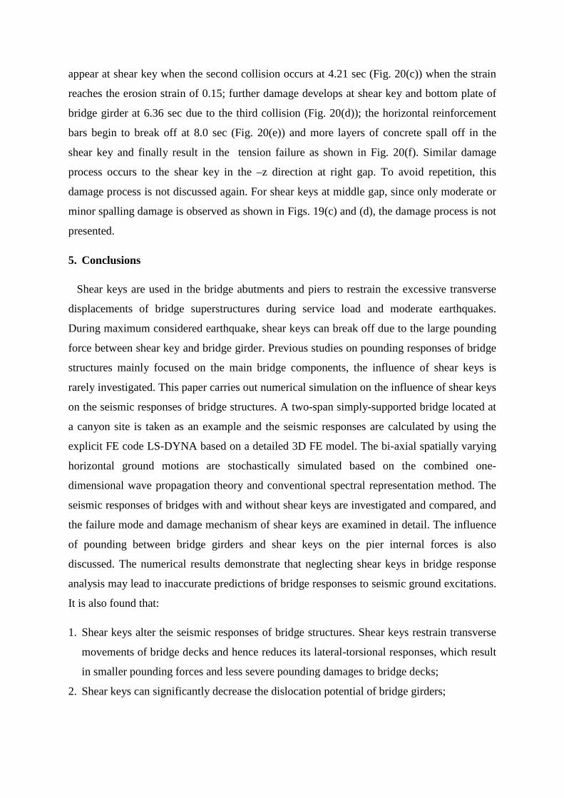
appear at shear key when the second collision occurs at 4.21 sec (Fig. 20(c)) when the strain
reaches the erosion strain of 0.15; further damage develops at shear key and bottom plate of
bridge girder at 6.36 sec due to the third collision (Fig. 20(d)); the horizontal reinforcement
bars begin to break off at 8.0 sec (Fig. 20(e)) and more layers of concrete spall off in the
shear key and finally result in the tension failure as shown in Fig. 20(f). Similar damage
process occurs to the shear key in the –z direction at right gap. To avoid repetition, this
damage process is not discussed again. For shear keys at middle gap, since only moderate or
minor spalling damage is observed as shown in Figs. 19(c) and (d), the damage process is not
presented.
5. Conclusions
Shear keys are used in the bridge abutments and piers to restrain the excessive transverse
displacements of bridge superstructures during service load and moderate earthquakes.
During maximum considered earthquake, shear keys can break off due to the large pounding
force between shear key and bridge girder. Previous studies on pounding responses of bridge
structures mainly focused on the main bridge components, the influence of shear keys is
rarely investigated. This paper carries out numerical simulation on the influence of shear keys
on the seismic responses of bridge structures. A two-span simply-supported bridge located at
a canyon site is taken as an example and the seismic responses are calculated by using the
explicit FE code LS-DYNA based on a detailed 3D FE model. The bi-axial spatially varying
horizontal ground motions are stochastically simulated based on the combined one-
dimensional wave propagation theory and conventional spectral representation method. The
seismic responses of bridges with and without shear keys are investigated and compared, and
the failure mode and damage mechanism of shear keys are examined in detail. The influence
of pounding between bridge girders and shear keys on the pier internal forces is also
discussed. The numerical results demonstrate that neglecting shear keys in bridge response
analysis may lead to inaccurate predictions of bridge responses to seismic ground excitations.
It is also found that:
1. Shear keys alter the seismic responses of bridge structures. Shear keys restrain transverse
movements of bridge decks and hence reduces its lateral-torsional responses, which result
in smaller pounding forces and less severe pounding damages to bridge decks;
2. Shear keys can significantly decrease the dislocation potential of bridge girders;
3. Poundings between bridge girders and shear keys can increase the internal forces in the
bridge piers in the transverse direction and therefore increase the damage potential of
bridge piers.
The current study demonstrated the important influences of poundings between bridge deck
and shear keys, which are normally neglected, on bridge structural responses when they are
subjected to earthquake ground motions. It should be noted that many parameters, for
example SSI, vertical earthquake loading, the dimensions of shear keys, ground motion
spatial variations, gap size at expansion joints and gap size between shear key and bridge
girder, may significantly influence the structural responses. Further parametric investigations
are needed to study the influences of these parameters on pounding responses of shear keys.
Acknowledgement
The authors acknowledge the partial financial support from ARC Linkage Project
LP110200906 for carrying out this research.
References
[1] Lee GC. The 512 Wenchuan earthquake of China-a preliminary report. MCEER,
University at Buffalo. http://mceer.buffalo.edu/research/Reconnaissance/China5-12-
08/ChinaEQ6-15-08.pdf.
[2] Li J, Peng T, Xu, Y. Damage investigation of girder bridges under Wenchuan earthquake
and corresponding seismic design recommendations. Earthq Eng Eng Vib 2008; 7(4), 337-
44.
[3] Schanack F, Valdebenito G, Alvial J. Seismic damage to bridges during the 27 February
2010 magnitude 8.8 Chile Earthquake. Earthq Spectra 2012; 28(1): 301-15.
[4] Jankowski R, Wilde K, Fujino Y. Pounding of superstructure segments in isolated
elevated bridge during earthquakes. Earthq Eng Struct Dyn 1998; 27(5): 487-502.
[5] DesRoches R, Muthukumar S. Effect of pounding and restrainers on seismic response of
multi-frame bridges. J Struct Eng-ASCE 2002; 128(7): 860-9.
[6] Guo A, Li Z, Li H, Ou J. Experimental and analytical study on pounding reduction of
base-isolated high way bridges using MR damper. Earthq Eng Struct Dyn 2009; 38(11):
1307-33.
[7] Hao H, Bi K, Chouw N, Ren WX. State-of-the-art review on seismic induced pounding
response of bridge structures. J Earthq and Tsunami 2013; 7(3): 1350019.
[8] Bi K, Hao H, Chouw N. 3D FEM analysis of pounding response of bridge structures at a
canyon site to spatially varying ground motions. Adv Struct Eng 2013; 16(4): 631-52.
[9] Bi K, Hao H. Numerical simulation of pounding damage to bridge structures under
spatially varying ground motions. Eng Struct 2013; 46: 62-76.
[10] Bozorgzadeh A, Megally S, Restrepo J. Seismic response of sacrificial exterior shear
keys in bridge abutments: recommended design and construction details. Report to
CALTRANS, Contract No. 59A0337, Department of Structural Engineering, UC San
Diego, San Diego.
[11] Bozorgzadeh A, Megally S, Restrepo J, Ashford SA. Capacity evaluation of exterior
sacrificial shear keys of bridge abutments. J Bridge Eng-ASCE 2006; 11(5): 555-65.
[13] Silva PF, Megally S, Seible F. Seismic performance of sacrificial interior shear keys.
ACI Struct J 2003; 100(2): 177-87.
[14] Silva PF, Megally S, Seible F. Seismic performance of sacrificial exterior shear keys in
bridge abutments. Earthq Spectra 2011; 25(3): 643-64.
[15] Maleki S. Effect of side retainers on seismic response of bridges with elastomeric
bearings. J Bridge Eng-ASCE 2004; 9(1): 95-100.
[16] Maleki S. Seismic modelling of skewed bridges with elastomeric bearings and side
retainers. J Bridge Eng-ASCE 2005; 10(4), 442-9.
[17] Goel RK, Chopra AK. Role of shear keys in seismic behaviour of bridges crossing fault-
rupture zones. J Bridge Eng-ASCE 2008; 13(4): 398-408.
[18] Chouw N, Hao H. Study of SSI and non-uniform ground motions effects on pounding
between bridge girders. Soil Dyn Earthq Eng 2005; 23: 717-28.
[19] Chouw N, Hao H. Significance of SSI and non-uniform near-fault ground motions in
bridge response I: effect on response with conventional expansion joint. Eng Struct 2008;
30(1): 141-53.
[20] Zhu P, Abe M, Fujino Y. Modelling three-dimensional non-linear seismic performance
of elevated bridges with emphasis on pounding of girders. Earthq Eng Struct Dyn 2002;
31:1891-913.
[21] Abdel Raheem SE. Pounding mitigation and unseating prevention at expansion joints of
isolated multi-span bridges, Eng Struct 2009; 31(10): 2345-56.
[22] Jankowski R. Non-linear FEM analysis of earthquake-induced pounding between the
main building and the stairway tower of the Olive View Hospital. Eng Struct 2009; 31(8):
1851-64.
[23] Jankowski R. Non-linear FEM analysis of pounding-involved response of buildings
under non-uniform earthquake excitation. Eng Struct 2012; 37: 99-105.
[24] LS-DYNA. LD-DYNA user manual. Livermore Software Technology Corporation;
2007.
[25] Hao Y, Hao H, Zhang XH. Numerical analysis of concrete material properties at high
strain rate under direct tension. Inte J of Impact Eng 2012; 39: 51-62.
[26] Hao Y, Hao H. Numerical evaluation of the influence of aggregates on concrete
compressive strength at high strain rate. Int J of Prot Struct 2011; 2(2): 177-206.
[27] Hao Y, Hao H, Li ZX. Influence of end friction confinement on impact tests of concrete
material at high strain rate. Int J of Prot Struct 2013; 60: 82-106.
[28] Malvar LJ. Review of static and dynamic properties of steel reinforcing bars. ACI Mater
J 1998; 95(6): 609-16.
[29] Bi K, Hao H. Modelling and simulation of spatially varying earthquake ground motions
at sites with varying conditions. Probabilistic Eng Mech 2012; 29: 92-104.
[30] Wang S, Hao H. Effects of random variations of soil properties on site amplification of
seismic ground motions. Soil Dyn Earthq Eng 2002; 22: 551-64.
[31] Sobczky K. Stochastic wave propagation. Netherlands: Kluwer Academic Publishers;
1991.
[32] Chopra, A.K. Dynamics of structures: theory and applications to earthquake engineering.
New Jersey: Prentice-Hall; 1995.
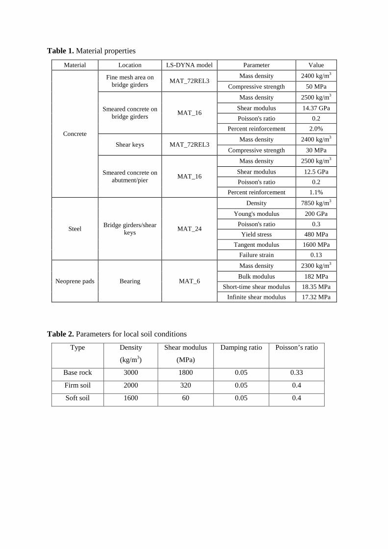
Table 1. Material properties
Material Location LS-DYNA model Parameter Value
Concrete
Fine mesh area on bridge girders MAT_72REL3
Mass density 2400 kg/m3
Compressive strength 50 MPa
Smeared concrete on bridge girders MAT_16
Mass density 2500 kg/m3
Shear modulus 14.37 GPa Poisson's ratio 0.2
Percent reinforcement 2.0%
Shear keys MAT_72REL3 Mass density 2400 kg/m3
Compressive strength 30 MPa
Smeared concrete on abutment/pier MAT_16
Mass density 2500 kg/m3
Shear modulus 12.5 GPa Poisson's ratio 0.2
Percent reinforcement 1.1%
Steel Bridge girders/shear keys MAT_24
Density 7850 kg/m3
Young's modulus 200 GPa Poisson's ratio 0.3
Yield stress 480 MPa Tangent modulus 1600 MPa
Failure strain 0.13
Neoprene pads Bearing MAT_6
Mass density 2300 kg/m3
Bulk modulus 182 MPa Short-time shear modulus 18.35 MPa
Infinite shear modulus 17.32 MPa
Table 2. Parameters for local soil conditions
Type Density
(kg/m3)
Shear modulus
(MPa)
Damping ratio Poisson’s ratio
Base rock 3000 1800 0.05 0.33
Firm soil 2000 320 0.05 0.4
Soft soil 1600 60 0.05 0.4
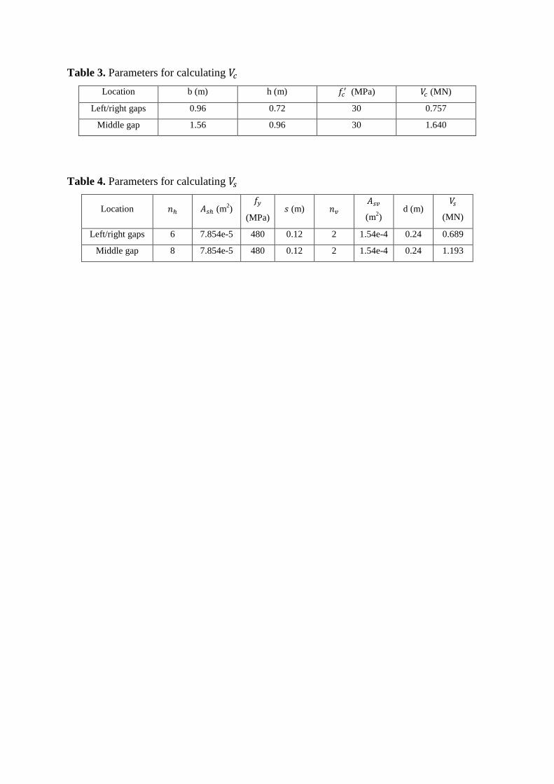
Table 3. Parameters for calculating 𝑉𝑉𝑐𝑐 Location b (m) h (m) 𝑓𝑓𝑐𝑐′ (MPa) 𝑉𝑉𝑐𝑐 (MN)
Left/right gaps 0.96 0.72 30 0.757
Middle gap 1.56 0.96 30 1.640
Table 4. Parameters for calculating 𝑉𝑉𝑠𝑠
Location 𝑛𝑛ℎ 𝐴𝐴𝑠𝑠ℎ (m2) 𝑓𝑓𝑦𝑦
(MPa) 𝑠𝑠 (m) 𝑛𝑛𝑣𝑣
𝐴𝐴𝑠𝑠𝑣𝑣
(m2) d (m)
𝑉𝑉𝑠𝑠
(MN)
Left/right gaps 6 7.854e-5 480 0.12 2 1.54e-4 0.24 0.689
Middle gap 8 7.854e-5 480 0.12 2 1.54e-4 0.24 1.193
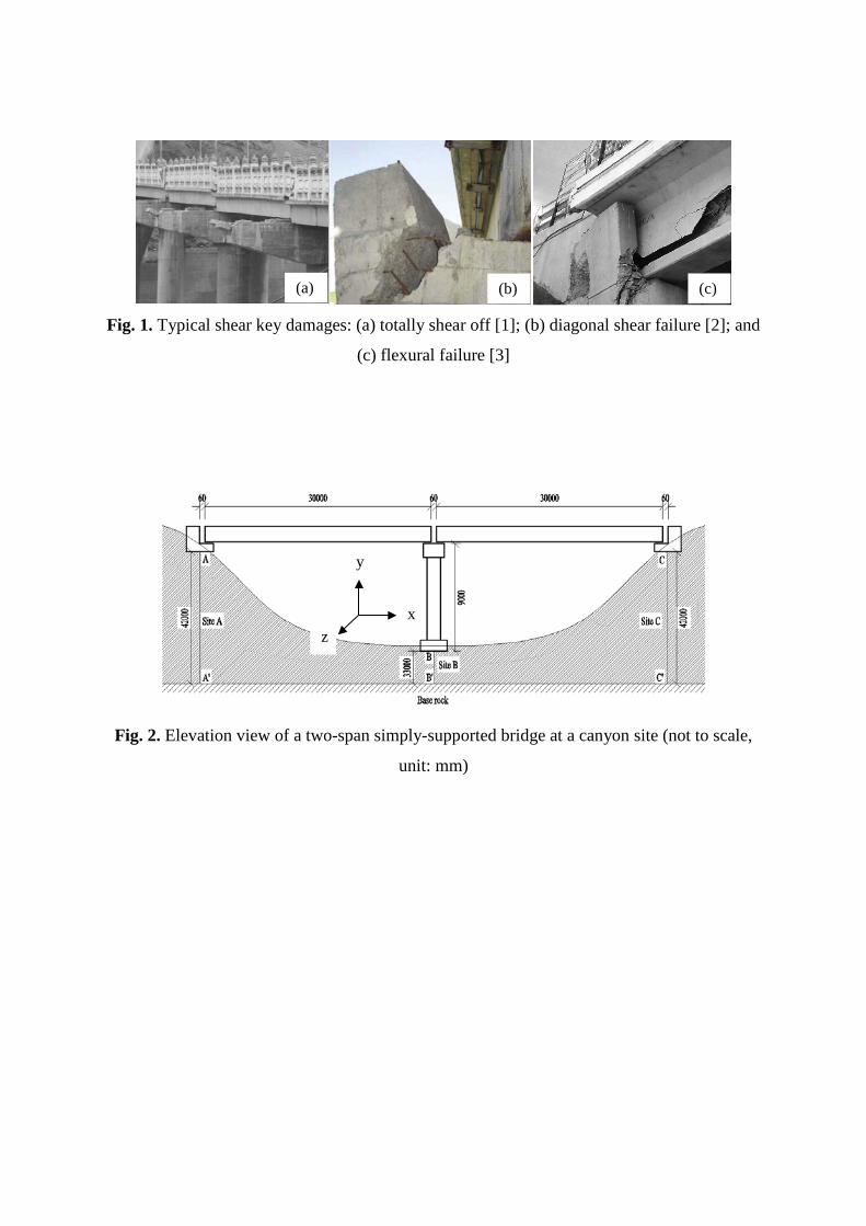
Fig. 1. Typical shear key damages: (a) totally shear off [1]; (b) diagonal shear failure [2]; and
(c) flexural failure [3]
Fig. 2. Elevation view of a two-span simply-supported bridge at a canyon site (not to scale,
unit: mm)
(a) (b) (c)
x
y
z
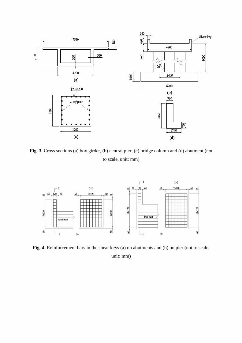
Fig. 3. Cross sections (a) box girder, (b) central pier, (c) bridge column and (d) abutment (not
to scale, unit: mm)
Fig. 4. Reinforcement bars in the shear keys (a) on abutments and (b) on pier (not to scale,
unit: mm)
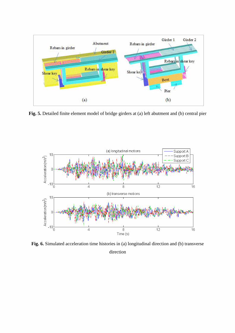
Fig. 5. Detailed finite element model of bridge girders at (a) left abutment and (b) central pier
Fig. 6. Simulated acceleration time histories in (a) longitudinal direction and (b) transverse
direction
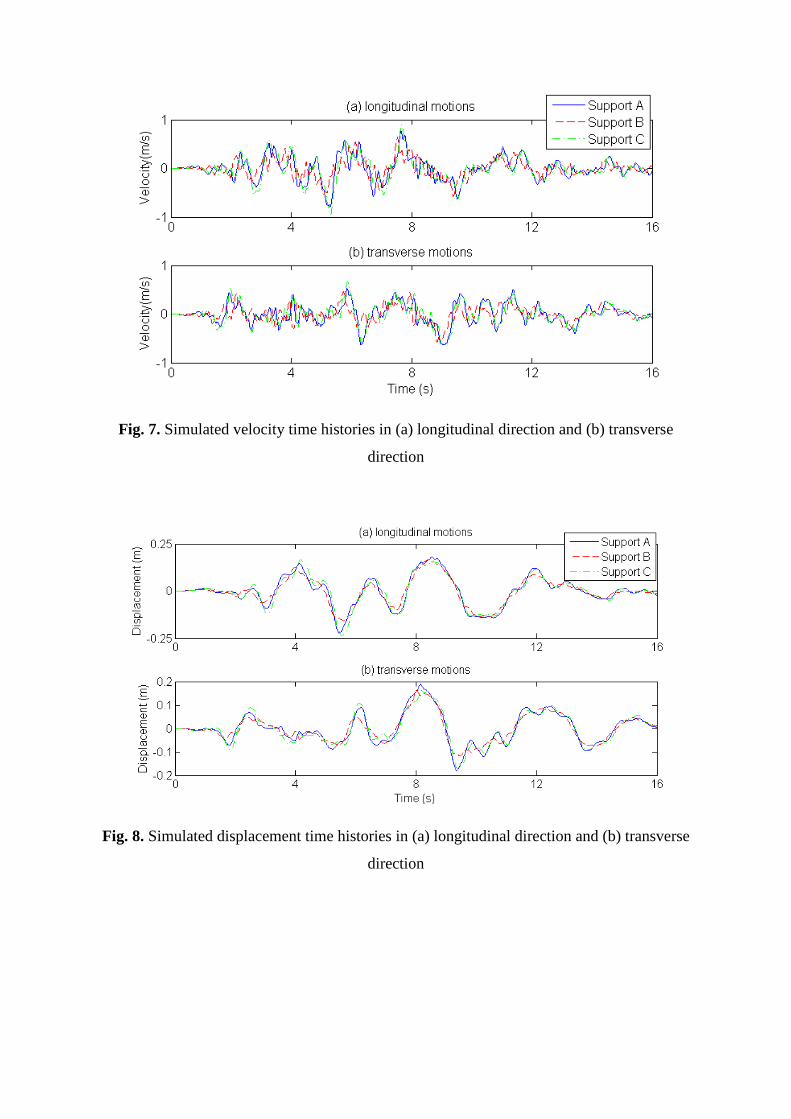
Fig. 7. Simulated velocity time histories in (a) longitudinal direction and (b) transverse
direction
Fig. 8. Simulated displacement time histories in (a) longitudinal direction and (b) transverse
direction
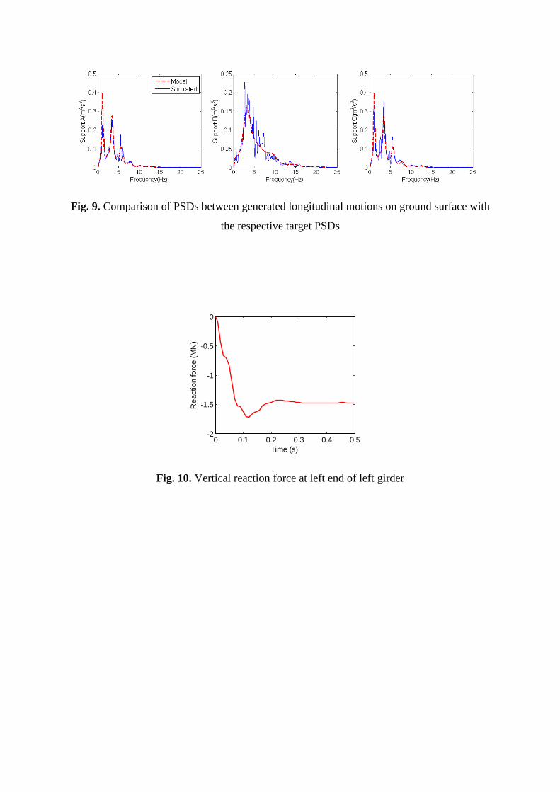
Fig. 9. Comparison of PSDs between generated longitudinal motions on ground surface with
the respective target PSDs
Fig. 10. Vertical reaction force at left end of left girder
0 0.1 0.2 0.3 0.4 0.5-2
-1.5
-1
-0.5
0
Time (s)
Rea
ctio
n fo
rce
(MN
)
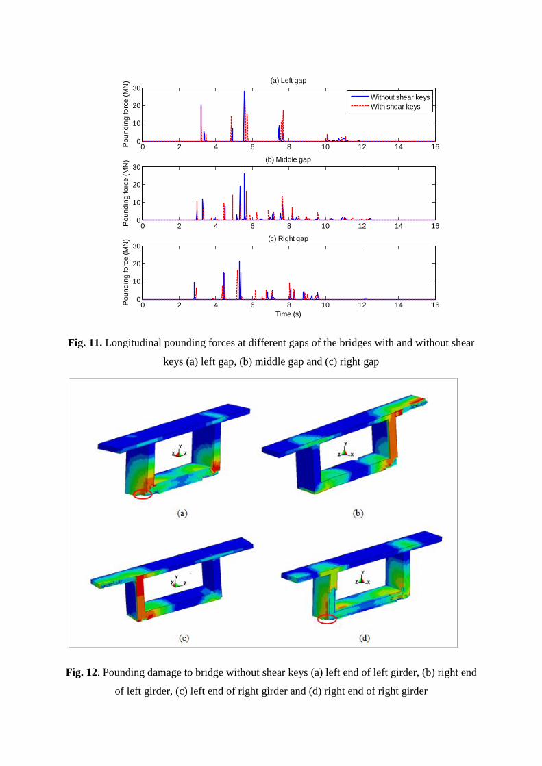
Fig. 11. Longitudinal pounding forces at different gaps of the bridges with and without shear
keys (a) left gap, (b) middle gap and (c) right gap
Fig. 12. Pounding damage to bridge without shear keys (a) left end of left girder, (b) right end
of left girder, (c) left end of right girder and (d) right end of right girder
0 2 4 6 8 10 12 14 160
10
20
30
Pou
ndin
g fo
rce
(MN
) (a) Left gap
Without shear keysWith shear keys
0 2 4 6 8 10 12 14 160
10
20
30
Pou
ndin
g fo
rce
(MN
) (b) Middle gap
0 2 4 6 8 10 12 14 160
10
20
30
Pou
ndin
g fo
rce
(MN
) (c) Right gap
Time (s)
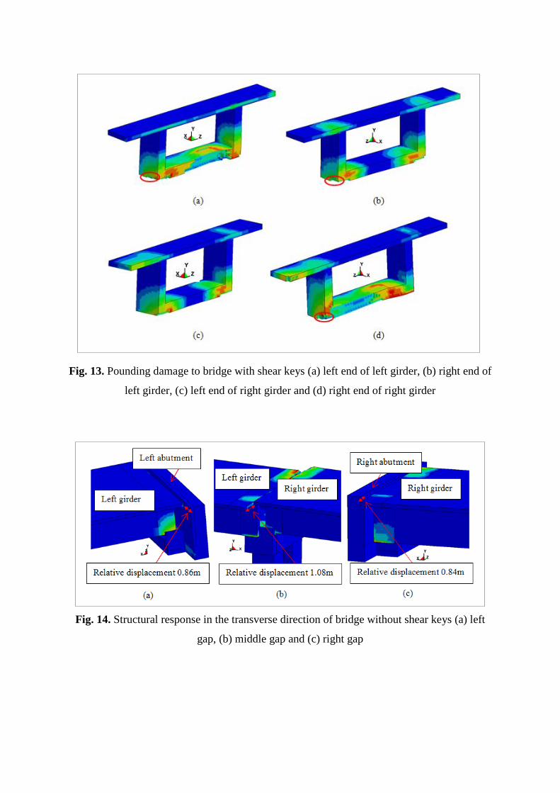
Fig. 13. Pounding damage to bridge with shear keys (a) left end of left girder, (b) right end of
left girder, (c) left end of right girder and (d) right end of right girder
Fig. 14. Structural response in the transverse direction of bridge without shear keys (a) left
gap, (b) middle gap and (c) right gap
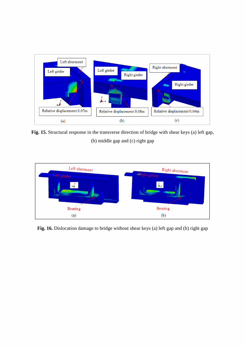
Fig. 15. Structural response in the transverse direction of bridge with shear keys (a) left gap,
(b) middle gap and (c) right gap
Fig. 16. Dislocation damage to bridge without shear keys (a) left gap and (b) right gap
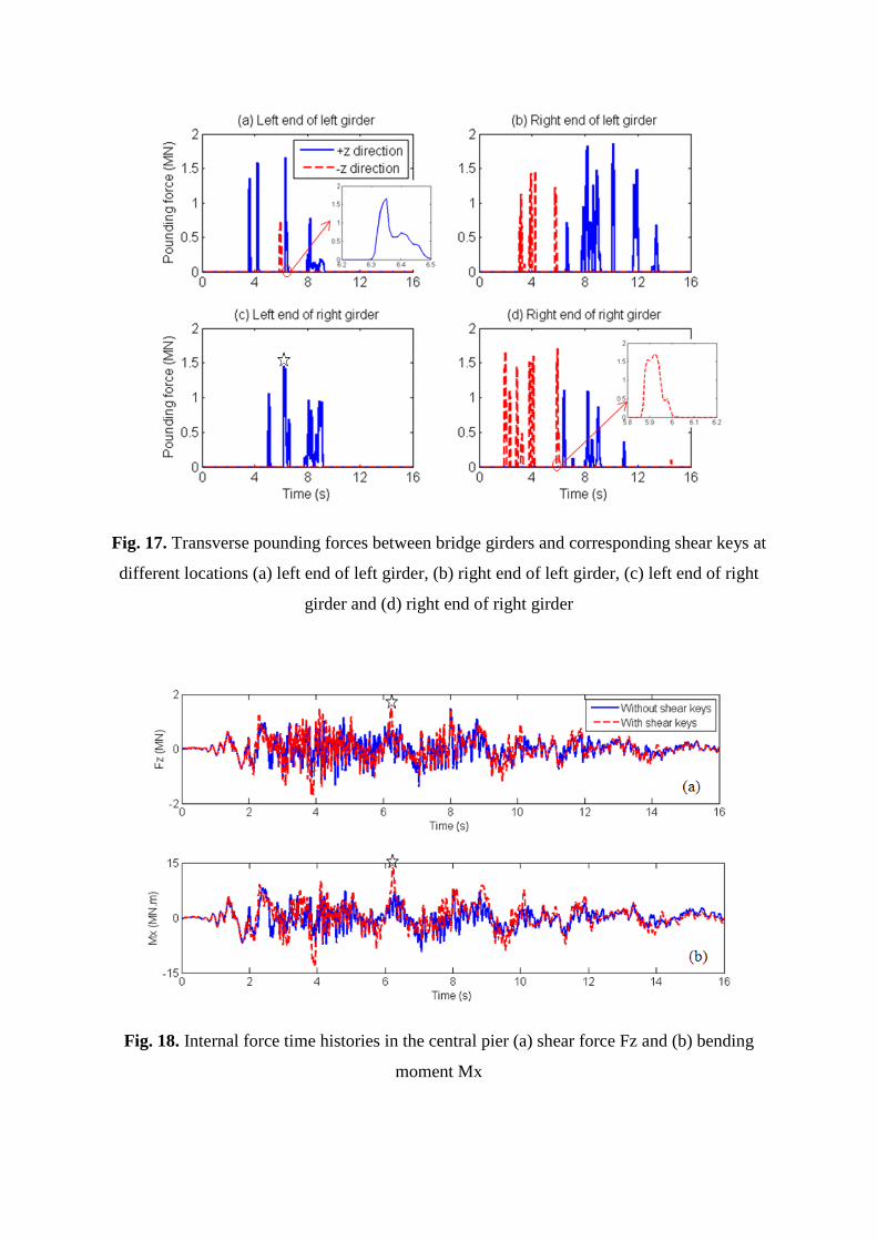
Fig. 17. Transverse pounding forces between bridge girders and corresponding shear keys at
different locations (a) left end of left girder, (b) right end of left girder, (c) left end of right
girder and (d) right end of right girder
Fig. 18. Internal force time histories in the central pier (a) shear force Fz and (b) bending
moment Mx
(a) (b) (c) (d) (e) (f)
Fig. 19. Pounding damage to shear keys at different locations (a) +z direction at left gap, (b)
–z direction at left gap, (c) +z direction at middle gap, (d) –z direction at middle gap, (e) +z
direction at right gap and (f) –z direction at right gap
Fig. 20. Snapshots of pounding damage between left end of left girder and shear key in the
+z direction at left gap (a) t=0 s, (b) t=3.57 s, (c) t=4.21 s, (d) t=6.36 s, (e) t=8.00 s and (f)
t=16 s