Embed Size (px)
Citation preview

1
NUMERICAL MODELING OF SHIP COLLISION BASED ON FINITE ELEMENT CODES O. Ozguc, P.K. Das, N. Barltrop & M. Shahid, Universities of Glasgow and Strathclyde, UK M. Samuelides, National Technical University of Athens, Greece
ABSTRACT
Non-linear finite element method (FEM) is a powerful tool for analysing ship collision problem and has been seen more and more applications in the recent years. Expectedly, more and more FEM simulation application will be seen in the coming years. Rapid advances in computer technology and software capacity have made FEM simulation a viable choice [17]. Ship collision simulations still face some difficulties in terms of providing reliable results. The accuracy of numerical modelling results significantly depends on the proper definition of the phenomenon and careful control of the some critical parameters such as rupture criteria, non-linearity, element type, friction coefficient, and mesh fineness. Present paper attempts to investigate the parameters on the ship collisions and provides effective guidelines on the implementation of the finite element codes.
NOMENCLATURE
el An individual element length eff
Pε Effective plastic strain
oσ Initial yield stress H The height of rupture aperture in the side shell (m) and t is the side shell thickness (cm)
eε The necking strain
CW The total energy absorbed by damage and striking and struck vessels in MJ
gε The uniform strain
yσ The yield function of plastic-kinematics material C , P Cowder – Symonds strain rate parameters
max1T Design draft of the striking ship
min1T Ballast draft of the striking ship
min2T Ballast draft of the struck ship
max2T Design draft of the struck ship β Hardening parameter between 0 (kinematics) and 1 (isotropic) LN , Ln Length of damage for the N-th member of the striking vessel or for the n-th member of struck vessel, respectively
PE Plastic hardening modulus PN , Pn Depth of damage for N-th member of striking vessels or for the n-th member of struck vessel, respectively,
TR The damaged volume of structural steel in m3 t The plate thickness
tN , tn Thickness of the N-th member of the striking vessel or of the n-th member of the struck vessel, respectively 1. INTRODUCTION Since early 1990’s, many predictive calculation procedures have been developed for predicting the ship responses in a collision or grounding. These methods have matured to such a level that they are now being integrated into systems for evaluation and designs. Nevertheless, how to calculate the ship responses in an accident continues to stand in the center of the recent research and development [17]. Analysis of the collision and grounding accidents can be classified into two parts, namely the external dynamics and internal mechanics. While the external dynamics deals with the rigid body global motion of ships under action of the collision or grounding forces and the hydrodynamic pressures acting on the wet surface. The internal mechanics includes evaluation of the structural failure response of the involved ships during the collision or grounding accident. Those two parts are often treated separately and in some cases solved together [20]. The analysis methods of internal mechanisms can be categorized into four groups: simple empirical formulae, simplified analytical approach, simplified FEM and non-linear FEM simulation. The internal mechanics involve yielding, tearing
2
or fracture. A non-linear FEM codes for simulating the structural behaviour needs to be fine mesh enough so as to capture such highly non-linear characteristics [15]. Non-linear finite element (FEM) is a powerful tool for analysing ship collision problem and has been seen more and more applications in the recent years. Expectedly, many more FEM simulation application will be seen in the coming years. Rapid advances in computer technology and software capacity have made FEM simulation a viable choice. Ship collision simulations still face some difficulties in terms of providing reliable results. The reliability of the numerical simulation results largely depends on the proper modelling of the phenomenon and realistic consideration of aspects, such as rupture criteria, non-linearity, element type, friction coefficient, and mesh fineness. This paper investigates the parameters on the ship collisions and provides effective guidelines on the implementation of FEM codes. It will thus be possible to compare the crashworthiness of various structural arrangements under similar collision scenarios. 2. NUMERICAL SIMULATION Recent advances in computers and calculation algorithms have made non-linear finite element analysis a viable tool for assessing the internal mechanics of collisions. Two types of FE methodologies are relevant, namely implicit and explicit techniques. Implicit methodologies obtain solution by simultaneous solving of systems of equations needing frequent updating of the stiffness matrix for nonlinear FE analysis. This places demands on the equation solver and the computer capacity especially in terms of memory resources and CPU cycles. Explicit codes obtain system solutions based on mass matrix that remain constant not needing frequent updating as in the case of stiffness approach. Explicit method however needs smaller time steps to comply with stability requirement for equation solving. To analyse a collision and grounding accident involving high non-linearity and phenomena such as colliding surfaces contact, friction and rupture, the explicit methodology is suitable. The required calculation efforts are fewer than the commonly
used implicit methods. Converge of calculations is much easier to realize. Explicit methodologies based computer codes include ABAQUS/Explicit, DYTRAN, LS-DYNA, PAM-CRASH and RADIOSS, and implicit methodologies based codes include ABAQUS/Standard, ANSYS, MARC and NASTRAN. There are mainly two important factors to consider in structural modelling of the non-linear FEM analysis, namely element type and mesh fineness. A higher order element generally provides better accuracy and allows coarse mesh. But this requires more computational effort because of the higher order of the element being used. The importance of mesh fineness or element types has been studied by many researchers including Kuroiwa [6], Kitamura [4], [5], Servis et al. [11], Ozguc et al. [9]. It is observed that a very large number of elements are required in order to obtain accurate results for components deformed by axial crushing forces. Accounting for realistic size and boundary conditions of FE models has been discussed by Woisin [16]. Application of non-linear FEM simulation has been the main theme of recent studies (Wu et al. [17], Zhang et al. [20], Tornqvist & Simonsen [13], Wang et al. [15], Alsos & Amdahl [1], Oh et al. [7], Yamada et al. [19]). Since structures behave in many complex patterns, many special modelling techniques are needed. Challenges involved in analysing such a high non-linear problem include among others, structural contact, criteria for material’s rupture, crack propagation (Wang et al. [15]). This trend was clearly demonstrated in the 2nd and 3rd International Conference on Collision and Grounding of Ships. 3. RUPTURE CRITERIA The modelling of rupture and tearing is the most challenging task in applying the structural crashworthy concept. This also forms the crucial background for the important criteria of crashworthy ships. Advanced FEM packages enable reliable automated simulation of the structural failure process up to occurrence of fracture, beyond which aids to the software, such as a user-defined subroutine, are needed for tracing the initiation and propagation of cracks.
3
Traditionally, rupture is assumed to occur when the equivalent plastic strain in an analysed structure reaches a critical value. This critical value, sometimes referred to as rupture strain, is related to the strain-stress curves obtained from mechanical tests of uni-axially stretched metal coupons. In the simplified analytical approaches, the rupture strain varies from 1% to 20% and is normally determined based on calibration or judgement. There has been an interest in defining rupture strain for FEM analyses. This critical value is found to be dependent on mesh size. Ranges of rupture strain were studied by Simonsen & Tornqvist [13], Okazawa et al. [8], Yamada & Endo [18], Alsos & Amdahl [1]. Refined simulation of fracture initiation and propagation requires that mesh size are small enough. This in turn makes the analysis of large ship structures very time consuming and computational demanding. It is well known that a failure criterion based on the equivalent strain is generally not valid in bi-axially loaded plates. Estimations of critical equivalent plastic strain as a function of the stress triaxiality using model tests and FEM analyses were reported in Urban [14], Tornqvist [12]. Several simple failure criteria and damage models were implemented in the explicit finite element code LS-DYNA. Tornqvist & Simonsen [13] have shown that the so-called RTCL (combined Rice-Tracey and Cockroft-Latham) criteria that account for the tri-axial nature of the fracture gives good comparison to the test results for different materials and various stress/strain states for validating these fracture criteria and damage models. The rupture failure may be explained using metal forming theory. The maximum strain that the material can sustain is limited by the local plastic instability. At the failure, plastic deformations concentrate on local areas. These areas have typical dimension of plate thickness. The failure process can be divided into diffuse necking and local necking phases. Diffuse necking develops slowly as a result of strain rate hardening, and occurs when the load reaches the maximum value. The final failure occurs by local necking during
which the deformation is concentrated on a small area away from which the structure remains almost un-deformed. This theory of localized necking has been developed for thin metal sheets, in which the assumption of plane stress is valid and the failure criteria can be based on the bi-axial principal strain state formulations. For typical ship structures the stress state is tri-axial, which complicates the development of simple rupture criteria. In this study, the definition of failure strain based on evaluation of the thickness measurements as recommended by Germanischer Lloyd [2] is employed due to its simplicity. The values of uniform strain and necking achieved from the thickness measurements are related to the calculated stress and are indicated in Table 1.
( )e
egef ltl εεε += (1)
Table 1. Proposed failure strain versus mesh size, [2]
Stress states 1-D 2-D εg 0.079 0.056
εe 0.76 0.54 Element type Beam-Truss Shell-Plate
4. BENCHMARKING PARTICULARS This section describes benchmark studies comparing numerical model results with the ISSC model tests including details of the finite element tools and general parameters used in the numerical analysis. 4.1 ISSC TEST The Association of Structural Improvement of Shipbuilding Industry of Japan [3] conducted extensive collision and grounding tests. One of the collision tests is a double side structure model made of mild steel struck by a model bow. In the dynamics test the bow model fell freely from a height of 4.8 m above the initial position of the outer hull, which gave an impact velocity of about 9.7 m/sec.
4
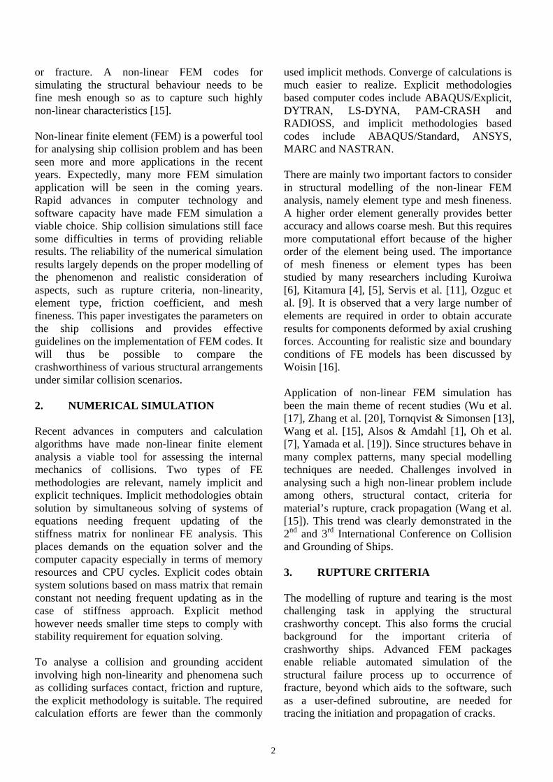
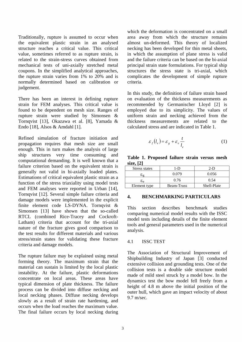
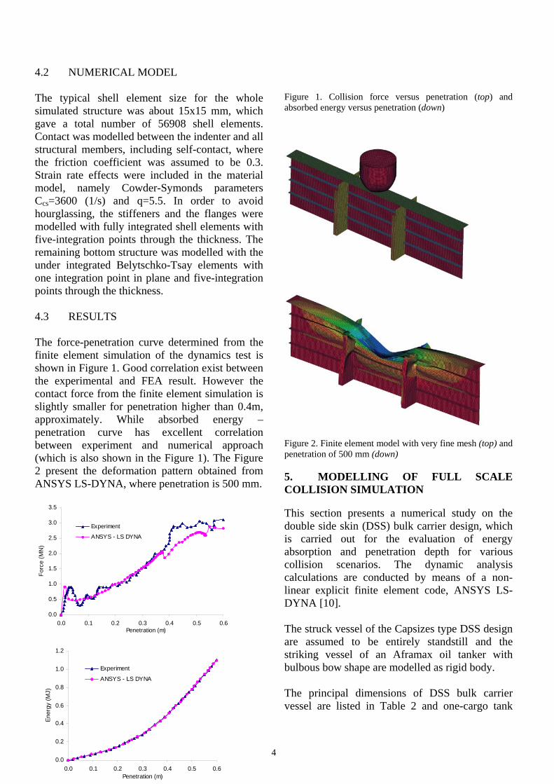
4.2 NUMERICAL MODEL The typical shell element size for the whole simulated structure was about 15x15 mm, which gave a total number of 56908 shell elements. Contact was modelled between the indenter and all structural members, including self-contact, where the friction coefficient was assumed to be 0.3. Strain rate effects were included in the material model, namely Cowder-Symonds parameters Ccs=3600 (1/s) and q=5.5. In order to avoid hourglassing, the stiffeners and the flanges were modelled with fully integrated shell elements with five-integration points through the thickness. The remaining bottom structure was modelled with the under integrated Belytschko-Tsay elements with one integration point in plane and five-integration points through the thickness. 4.3 RESULTS The force-penetration curve determined from the finite element simulation of the dynamics test is shown in Figure 1. Good correlation exist between the experimental and FEA result. However the contact force from the finite element simulation is slightly smaller for penetration higher than 0.4m, approximately. While absorbed energy – penetration curve has excellent correlation between experiment and numerical approach (which is also shown in the Figure 1). The Figure 2 present the deformation pattern obtained from ANSYS LS-DYNA, where penetration is 500 mm.
Figure 1. Collision force versus penetration (top) and absorbed energy versus penetration (down)
Figure 2. Finite element model with very fine mesh (top) and penetration of 500 mm (down) 5. MODELLING OF FULL SCALE COLLISION SIMULATION This section presents a numerical study on the double side skin (DSS) bulk carrier design, which is carried out for the evaluation of energy absorption and penetration depth for various collision scenarios. The dynamic analysis calculations are conducted by means of a non-linear explicit finite element code, ANSYS LS-DYNA [10]. The struck vessel of the Capsizes type DSS design are assumed to be entirely standstill and the striking vessel of an Aframax oil tanker with bulbous bow shape are modelled as rigid body. The principal dimensions of DSS bulk carrier vessel are listed in Table 2 and one-cargo tank
0.0
0.5
1.0
1.5
2.0
2.5
3.0
3.5
0.0 0.1 0.2 0.3 0.4 0.5 0.6Penetration (m)
Forc
e (M
N)
Experiment
ANSYS - LS DYNA
0.0
0.2
0.4
0.6
0.8
1.0
1.2
0.0 0.1 0.2 0.3 0.4 0.5 0.6Penetration (m)
Ener
gy (M
J)
Experiment
ANSYS - LS DYNA
5
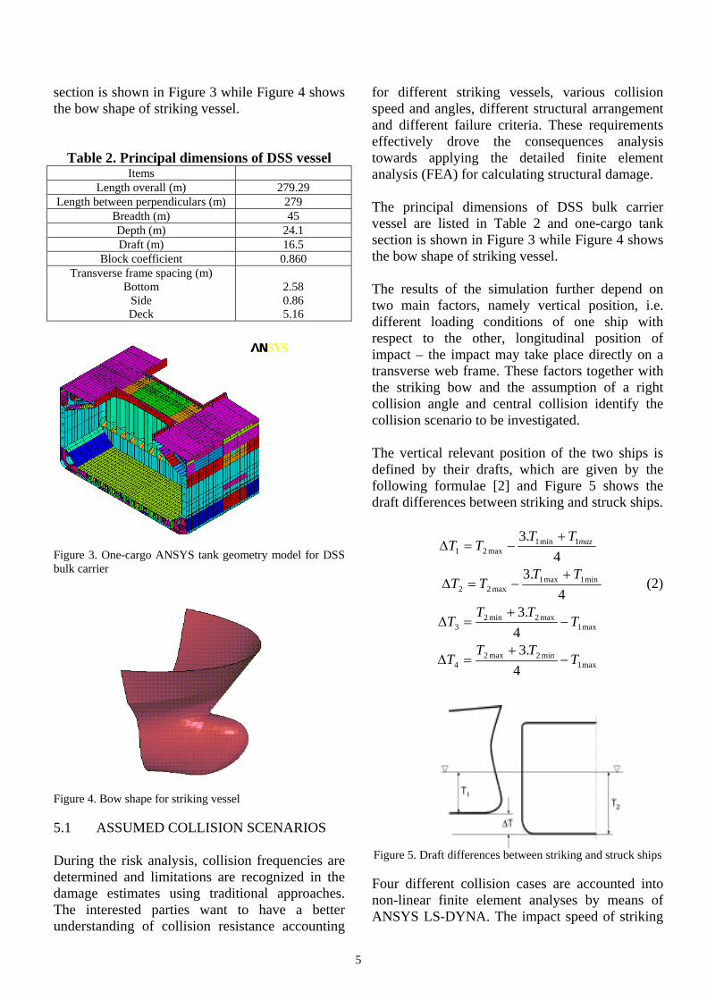
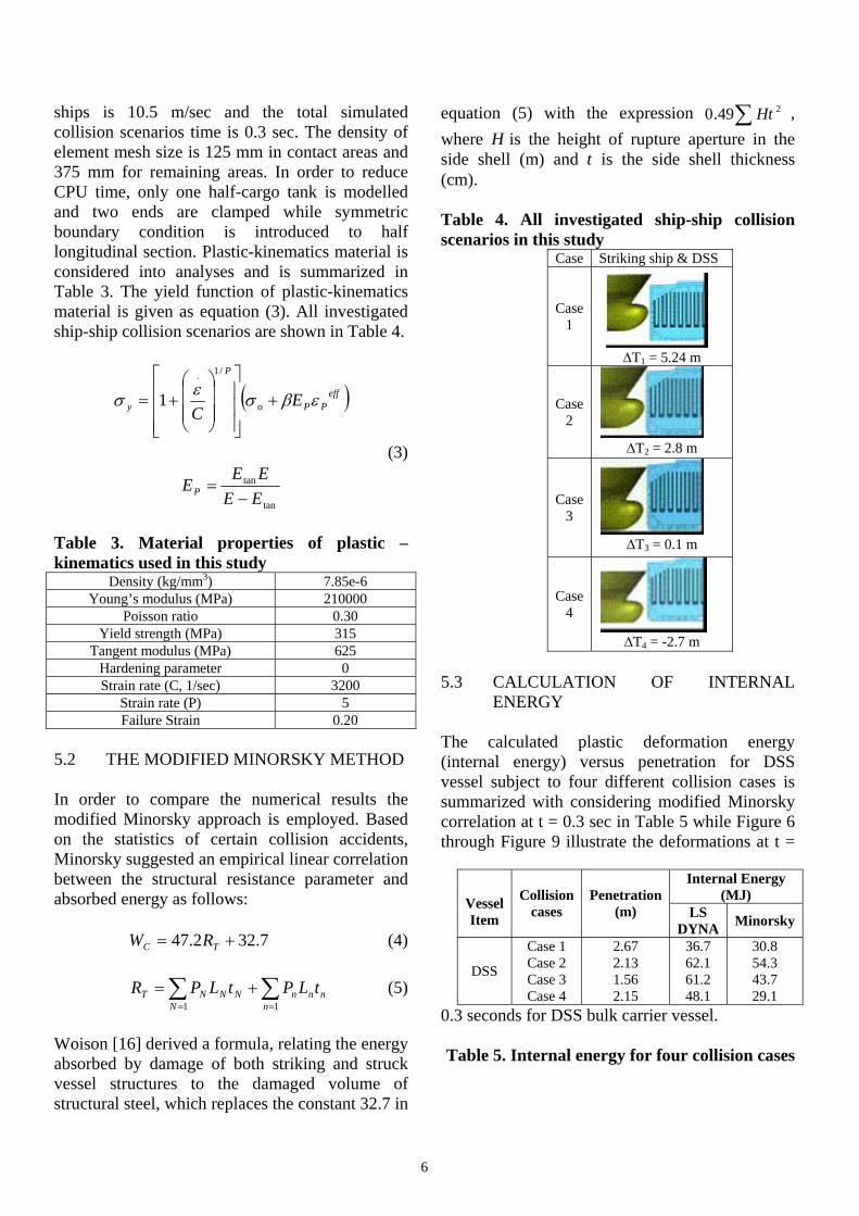
section is shown in Figure 3 while Figure 4 shows the bow shape of striking vessel.
Table 2. Principal dimensions of DSS vessel Items
Length overall (m) 279.29 Length between perpendiculars (m) 279
Breadth (m) 45 Depth (m) 24.1 Draft (m) 16.5
Block coefficient 0.860 Transverse frame spacing (m)
Bottom Side Deck
2.58 0.86 5.16
Figure 3. One-cargo ANSYS tank geometry model for DSS bulk carrier
Figure 4. Bow shape for striking vessel 5.1 ASSUMED COLLISION SCENARIOS During the risk analysis, collision frequencies are determined and limitations are recognized in the damage estimates using traditional approaches. The interested parties want to have a better understanding of collision resistance accounting
for different striking vessels, various collision speed and angles, different structural arrangement and different failure criteria. These requirements effectively drove the consequences analysis towards applying the detailed finite element analysis (FEA) for calculating structural damage. The principal dimensions of DSS bulk carrier vessel are listed in Table 2 and one-cargo tank section is shown in Figure 3 while Figure 4 shows the bow shape of striking vessel. The results of the simulation further depend on two main factors, namely vertical position, i.e. different loading conditions of one ship with respect to the other, longitudinal position of impact – the impact may take place directly on a transverse web frame. These factors together with the striking bow and the assumption of a right collision angle and central collision identify the collision scenario to be investigated. The vertical relevant position of the two ships is defined by their drafts, which are given by the following formulae [2] and Figure 5 shows the draft differences between striking and struck ships.
4.3 1min1
max21mazTT
TT+
−=∆
4.3 min1max1
max22TT
TT+
−=∆ (2)
max1max2min2
3 4.3
TTT
T −+
=∆
max1min2max2
4 4.3
TTT
T −+
=∆
Figure 5. Draft differences between striking and struck ships Four different collision cases are accounted into non-linear finite element analyses by means of ANSYS LS-DYNA. The impact speed of striking
6
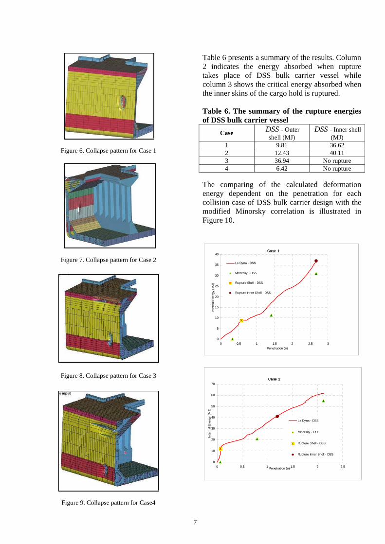
ships is 10.5 m/sec and the total simulated collision scenarios time is 0.3 sec. The density of element mesh size is 125 mm in contact areas and 375 mm for remaining areas. In order to reduce CPU time, only one half-cargo tank is modelled and two ends are clamped while symmetric boundary condition is introduced to half longitudinal section. Plastic-kinematics material is considered into analyses and is summarized in Table 3. The yield function of plastic-kinematics material is given as equation (3). All investigated ship-ship collision scenarios are shown in Table 4.
( )effPPo
P
y EC
εβσεσ +⎥⎥⎥
⎦
⎤
⎢⎢⎢
⎣
⎡
⎟⎟⎟
⎠
⎞
⎜⎜⎜
⎝
⎛+=
/1.
1
(3)
tan
tan
EEEE
EP −=
Table 3. Material properties of plastic – kinematics used in this study
Density (kg/mm3) 7.85e-6 Young’s modulus (MPa) 210000
Poisson ratio 0.30 Yield strength (MPa) 315
Tangent modulus (MPa) 625 Hardening parameter 0 Strain rate (C, 1/sec) 3200
Strain rate (P) 5 Failure Strain 0.20
5.2 THE MODIFIED MINORSKY METHOD In order to compare the numerical results the modified Minorsky approach is employed. Based on the statistics of certain collision accidents, Minorsky suggested an empirical linear correlation between the structural resistance parameter and absorbed energy as follows:
7.322.47 += TC RW (4)
∑ ∑= =
+=1 1N n
nnnNNNT tLPtLPR (5)
Woison [16] derived a formula, relating the energy absorbed by damage of both striking and struck vessel structures to the damaged volume of structural steel, which replaces the constant 32.7 in
equation (5) with the expression ∑ 249.0 Ht , where H is the height of rupture aperture in the side shell (m) and t is the side shell thickness (cm). Table 4. All investigated ship-ship collision scenarios in this study
Case Striking ship & DSS
Case 1
∆T1 = 5.24 m
Case 2
∆T2 = 2.8 m
Case 3
∆T3 = 0.1 m
Case 4
∆T4 = -2.7 m 5.3 CALCULATION OF INTERNAL
ENERGY The calculated plastic deformation energy (internal energy) versus penetration for DSS vessel subject to four different collision cases is summarized with considering modified Minorsky correlation at t = 0.3 sec in Table 5 while Figure 6 through Figure 9 illustrate the deformations at t =
0.3 seconds for DSS bulk carrier vessel. Table 5. Internal energy for four collision cases
Internal Energy (MJ)
Vessel Item
Collision cases
Penetration (m) LS
DYNA Minorsky
DSS
Case 1 Case 2 Case 3 Case 4
2.67 2.13 1.56 2.15
36.7 62.1 61.2 48.1
30.8 54.3 43.7 29.1
7
Figure 6. Collapse pattern for Case 1
Figure 7. Collapse pattern for Case 2
Figure 8. Collapse pattern for Case 3
Figure 9. Collapse pattern for Case4
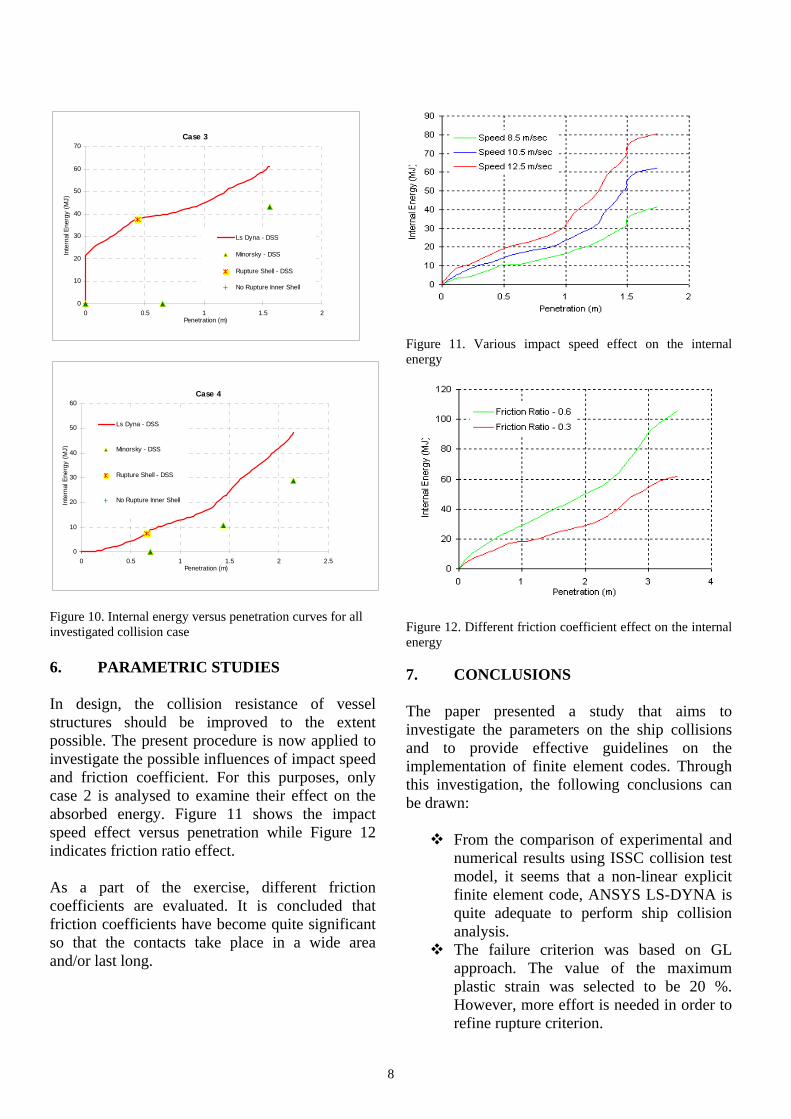
Table 6 presents a summary of the results. Column 2 indicates the energy absorbed when rupture takes place of DSS bulk carrier vessel while column 3 shows the critical energy absorbed when the inner skins of the cargo hold is ruptured. Table 6. The summary of the rupture energies of DSS bulk carrier vessel
Case DSS - Outer shell (MJ)
DSS - Inner shell (MJ)
1 9.81 36.62 2 12.43 40.11 3 36.94 No rupture 4 6.42 No rupture
The comparing of the calculated deformation energy dependent on the penetration for each collision case of DSS bulk carrier design with the modified Minorsky correlation is illustrated in Figure 10.
Case 1
0
5
10
15
20
25
30
35
40
0 0.5 1 1.5 2 2.5 3Penetration (m)
Inte
rnal
Ene
rgy
(MJ)
Ls Dyna - DSS
Minorsky - DSS
Rupture Shell - DSS
Rupture Inner Shell - DSS
Case 2
0
10
20
30
40
50
60
70
0 0.5 1 1.5 2 2.5Penetration (m)
Inte
rnal
Ene
rgy
(MJ)
Ls Dyna - DSS
Minorsky - DSS
Rupture Shell - DSS
Rupture Inner Shell - DSS
8
Figure 10. Internal energy versus penetration curves for all investigated collision case 6. PARAMETRIC STUDIES In design, the collision resistance of vessel structures should be improved to the extent possible. The present procedure is now applied to investigate the possible influences of impact speed and friction coefficient. For this purposes, only case 2 is analysed to examine their effect on the absorbed energy. Figure 11 shows the impact speed effect versus penetration while Figure 12 indicates friction ratio effect. As a part of the exercise, different friction coefficients are evaluated. It is concluded that friction coefficients have become quite significant so that the contacts take place in a wide area and/or last long.
Figure 11. Various impact speed effect on the internal energy
Figure 12. Different friction coefficient effect on the internal energy 7. CONCLUSIONS The paper presented a study that aims to investigate the parameters on the ship collisions and to provide effective guidelines on the implementation of finite element codes. Through this investigation, the following conclusions can be drawn:
From the comparison of experimental and numerical results using ISSC collision test model, it seems that a non-linear explicit finite element code, ANSYS LS-DYNA is quite adequate to perform ship collision analysis.
The failure criterion was based on GL approach. The value of the maximum plastic strain was selected to be 20 %. However, more effort is needed in order to refine rupture criterion.
Case 3
0
10
20
30
40
50
60
70
0 0.5 1 1.5 2Penetration (m)
Inte
rnal
Ene
rgy
(MJ)
Ls Dyna - DSS
Minorsky - DSS
Rupture Shell - DSS
No Rupture Inner Shell
Case 4
0
10
20
30
40
50
60
0 0.5 1 1.5 2 2.5Penetration (m)
Inte
rnal
Ene
rgy
(MJ)
Ls Dyna - DSS
Minorsky - DSS
Rupture Shell - DSS
No Rupture Inner Shell

9
The ship structural design has very significant influence on the collision resistance. The collision energy absorption capability depends on the thickness of outer shell, inner shell, side stringers, transverse webs, width of the side ballast tank and width of lower and upper wing tanks.
The results obtained from the finite element simulation may be used a) for the assessment of the collision behaviour of a ship under defined collision scenario, b) for the relative comparison of structural arrangements and c) for the validation of analytical techniques for ship collision analysis.
The rapid advances in computer technology make numerical simulation, a formidable task only a couple years ago, a viable choice now. Finite element technology offers reliable codes and elements that are suitable for solving very complex engineering problems including large displacements, large strains, and a contact provided that the proper definition of the problem is established.
ACKNOWLEDGEMENTS The work has been performed in the scope of the project MARSTRUCT, Network of Excellence on Marine Structures, (www.mar.ist.utl/marstruct/), which has been financed by the EU through the GROWTH Programme under contract TNE3-CT-2003-506141. REFERENCES [1] Alsos, H.S. and Amdahl, J. (2005). International grounding of disabled ships, Marine 2005 – Computational Methods in Marine Engineering, Oslo, Norway, 27-29 June 2005. [2] GL (1992). Rules for Classification and Construction Ship Technology Part –1 Seagoing Ships Chapter 1 Hull Structures Section 33 Strengthening against Collisions, Germanischer Lloyd, Hamburg, Germany. [3] ISSC. (2003). Committee V.3 Collision and Grounding. 15th International Ship and Offshore Structures Congress (ISSC), San Diego, USA. [4] Kitamura, O. (2001). FEM approach to simulate of collision and grounding damage, The Second International Conference on Collision and Grounding of the Ships, Copenhagen, Denmark. [5] Kitamura, O., Kuroiwa, T., Kawamoto, Y. and Kaneko, E. (1998). A study on the improved tanker structure against
collision and grounding damage, Proceedings of the 7th PRADS, 173-179. [6] Kuroiwa, T. (1996). Numerical simulation of the actual collision and grounding experiments, International Conference on Design and Methodologies for Collision and Grounding Protection of Ships, San Francisco, USA. [7] Oh, M., Kim, J.H., Jang, Y.S. and Bird, E. (2005). Impact analysis of Greater Plutonio FPSO considering ship collision, International Offshore and Polar Engineering Conference (ISOPE), Seoul, Korea, 19-24 June 2005. [8] Okazawa, S., Fujikubo, M. and Hiroi, S. (2004). Static and dynamic necking analysis of steel plates in tension, International Conference on Collision and Grounding of Ships (ICCGS), Izu, Japan, 25-27 October 2004. [9] Ozguc, O., Das, P.K. and Barltrop, N.D.P. (2005). A comparative study on the structural integrity of single and double side skin bulk carriers under collision damage, Marine Structures, 18: 511-547. [10] Ozguc, O., Samuelides, M. and Das, P.K. (2005). A comparative study on the collision resistance of single and double side skin bulk carriers, International Congress of International Maritime Association of the Mediterranean, Lisbon, Portugal, 26-30 September. [11] Servis, D.P., Samuelides, M., Louka, T. and Voudouris, G. (2002). The implementation of finite element codes for the simulation of ship-ship collisions, Journal of Ship Research, 46(4): 239-247. [12] Tornqvist, R. (2003). Design of Crashworthy Ship Structures, PhD thesis, Technical University of Denmark, Lyngby, Denmark. [13] Tornqvist, R. and Simonsen, B.C. (2004). Safety and structural crashworthiness of ship structures: Modelling tools and application in design, International Conference on Collision and Grounding of Ships (ICCGS), Izu, Japan, 25-27 October 2004. [14] Urban, J. (2003). Crushing and Fracture of Lightweight Structures, PhD thesis, Technical University of Denmark, Lyngby, Denmark. [15] Wang, G., Jiang, D.J. and Shin, Y. (2003). Consideration of collision and contact damage risks in FPSO structural design, OTC-15316, Offshore Technology Conference, Houston, TX, 5-8 May 2003. [16] Woisin, G. (1979). Design against collision. Proc of the First Int. Symposium on Advances in Marine Technology, Norway. [17] Wu, F., Spong, R. and Wang, G. (2004). Using numerical simulation to analyse ship collision, International Conference on Collision and Grounding of Ships (ICCGS), Izu, Japan, 25-27 October 2004. [18] Yamada, Y and Endo, H. (2004). Collapse strength of the buffer bow structure in oblique collision, International Conference on Collision and Grounding of Ships (ICCGS), Izu, Japan, 25-27 October 2004. [19] Yamada, Y., Endo, H. and Pedersen, P.T. (2005). Numerical study on the effect of buffer bow structure in ship-to-ship collisions, International Offshore and Polar Engineering Conference (ISOPE), Seoul, Korea, 19-24 June 2005. [20] Zhang, S., Ocakli, H. and Pedersen, P.T. (2004). Crushing of ship bows in head-on collision, International Journal of Maritime Engineering, Transactions of the Royal Institution of Naval Architects, 146:A2, 39-76.