Embed Size (px)
Citation preview
25th ICDERS August 2 – 7, 2015 Leeds, UK
Correspondence to: Shijie Liu, [email protected], [email protected]. 1
Numerical Investigation on the Airbreathing Continuous Rotating Detonation Engine
Shijie Liu, Weidong Liu, Luxin Jiang, Zhiyong Lin Science and Technology on Scramjet Laboratory, National University of Defense Technology,
Changsha 410073, China
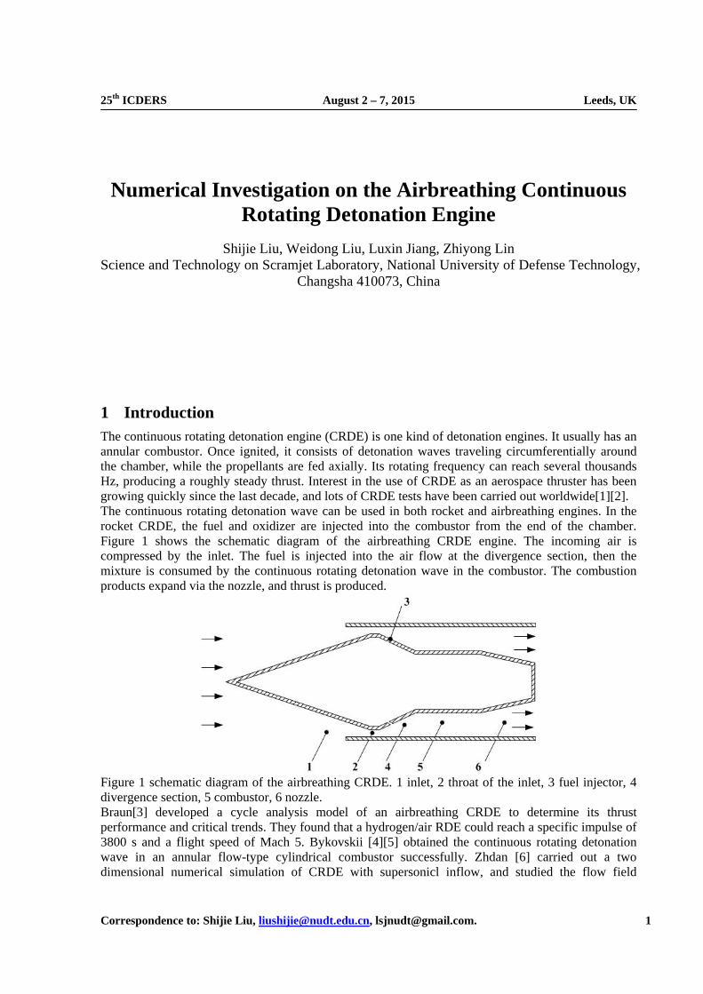
1 Introduction The continuous rotating detonation engine (CRDE) is one kind of detonation engines. It usually has an annular combustor. Once ignited, it consists of detonation waves traveling circumferentially around the chamber, while the propellants are fed axially. Its rotating frequency can reach several thousands Hz, producing a roughly steady thrust. Interest in the use of CRDE as an aerospace thruster has been growing quickly since the last decade, and lots of CRDE tests have been carried out worldwide[1][2]. The continuous rotating detonation wave can be used in both rocket and airbreathing engines. In the rocket CRDE, the fuel and oxidizer are injected into the combustor from the end of the chamber. Figure 1 shows the schematic diagram of the airbreathing CRDE engine. The incoming air is compressed by the inlet. The fuel is injected into the air flow at the divergence section, then the mixture is consumed by the continuous rotating detonation wave in the combustor. The combustion products expand via the nozzle, and thrust is produced.
Figure 1 schematic diagram of the airbreathing CRDE. 1 inlet, 2 throat of the inlet, 3 fuel injector, 4 divergence section, 5 combustor, 6 nozzle. Braun[3] developed a cycle analysis model of an airbreathing CRDE to determine its thrust performance and critical trends. They found that a hydrogen/air RDE could reach a specific impulse of 3800 s and a flight speed of Mach 5. Bykovskii [4][5] obtained the continuous rotating detonation wave in an annular flow-type cylindrical combustor successfully. Zhdan [6] carried out a two dimensional numerical simulation of CRDE with supersonicl inflow, and studied the flow field
Shijie Liu Numerical Investigation on the Airbreathing CRDE
25th ICDERS – August 2-7, 2015 - Leeds 2
structure carefully. Hishida [7] studied the fundamentals of continuous rotating detonation wave numerically, and found that the normal velocity of the rotating detonation wave was the vector sum of its rotating velocity and the unburnt gas injection velocity. Fujiwara [8] pointed out that the continuous rotating detonation wave could be stabilized for any incoming Mach number. Depending upon the incoming velocity, the inclination of the rotating detonation wave varied. For the incoming velocity equal to the Chapman-Jouguet value, the detonation surface becomed completely normal to the axis. This has been demonstrated numerically by Shao [9]. However, they ignored the interaction between the continous rotating detonation wave and the inflow. Schwer [10][11] examined the effect of pressure feedback into the mixture plenum caused by the CRDE numerically, and found that the pressure feedback could be significant, especially for the large area ratio cases. Three dimensional numerical simulation on the airbreathing CRDE was carried out in this papar. The flow field structure and effect of the continuous rotating detonation wave on the inflow were investigated. Through this research, the physics of the airbreathing CRDE would be better understood.
2 Physical model and numerical method The governing equations were the three-dimensional reactive Euler equations. To take care of the numerical stiffness, a time-operator splitting method was used. The flux terms were solved by a high resolution shock-capturing WENO (weighted essentially non-oscillatory) scheme, and time integration was performed by using a second-order Runge-Kutta method. A one-step, irreversible Arrhenius kinetics for H2/Air mixture was adopted in the present study. This model was particularly suitable for CRDE simulation, which had been used by Shao[9] and Liu[12][13] to compute the flow field structure of CRDE successfully.
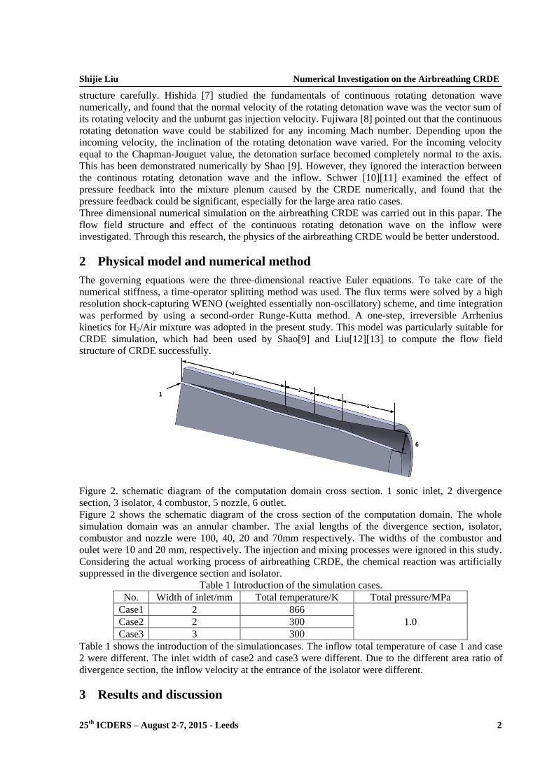
Figure 2. schematic diagram of the computation domain cross section. 1 sonic inlet, 2 divergence section, 3 isolator, 4 combustor, 5 nozzle, 6 outlet. Figure 2 shows the schematic diagram of the cross section of the computation domain. The whole simulation domain was an annular chamber. The axial lengths of the divergence section, isolator, combustor and nozzle were 100, 40, 20 and 70mm respectively. The widths of the combustor and oulet were 10 and 20 mm, respectively. The injection and mixing processes were ignored in this study. Considering the actual working process of airbreathing CRDE, the chemical reaction was artificially suppressed in the divergence section and isolator.
Table 1 Introduction of the simulation cases. No. Width of inlet/mm Total temperature/K Total pressure/MPa
Case1 2 866 1.0 Case2 2 300
Case3 3 300 Table 1 shows the introduction of the simulationcases. The inflow total temperature of case 1 and case 2 were different. The inlet width of case2 and case3 were different. Due to the different area ratio of divergence section, the inflow velocity at the entrance of the isolator were different.
3 Results and discussion
Shijie Liu Numerical Investigation on the Airbreathing CRDE
25th ICDERS – August 2-7, 2015 - Leeds 3
3.1 Flow-field structure
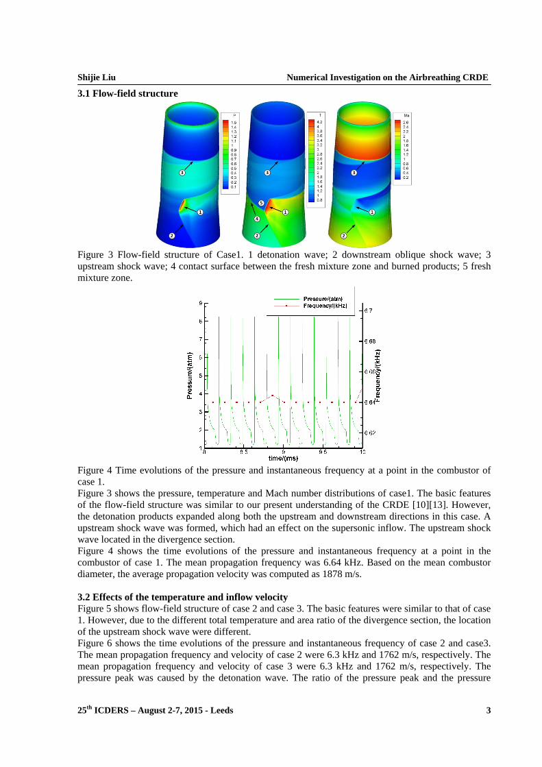
Figure 3 Flow-field structure of Case1. 1 detonation wave; 2 downstream oblique shock wave; 3 upstream shock wave; 4 contact surface between the fresh mixture zone and burned products; 5 fresh mixture zone.
Figure 4 Time evolutions of the pressure and instantaneous frequency at a point in the combustor of case 1. Figure 3 shows the pressure, temperature and Mach number distributions of case1. The basic features of the flow-field structure was similar to our present understanding of the CRDE [10][13]. However, the detonation products expanded along both the upstream and downstream directions in this case. A upstream shock wave was formed, which had an effect on the supersonic inflow. The upstream shock wave located in the divergence section. Figure 4 shows the time evolutions of the pressure and instantaneous frequency at a point in the combustor of case 1. The mean propagation frequency was 6.64 kHz. Based on the mean combustor diameter, the average propagation velocity was computed as 1878 m/s. 3.2 Effects of the temperature and inflow velocity Figure 5 shows flow-field structure of case 2 and case 3. The basic features were similar to that of case 1. However, due to the different total temperature and area ratio of the divergence section, the location of the upstream shock wave were different. Figure 6 shows the time evolutions of the pressure and instantaneous frequency of case 2 and case3. The mean propagation frequency and velocity of case 2 were 6.3 kHz and 1762 m/s, respectively. The mean propagation frequency and velocity of case 3 were 6.3 kHz and 1762 m/s, respectively. The pressure peak was caused by the detonation wave. The ratio of the pressure peak and the pressure
Shijie Liu Numerical Investigation on the Airbreathing CRDE
25th ICDERS – August 2-7, 2015 - Leeds 4
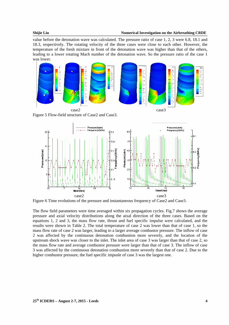
value before the detonation wave was calculated. The pressure ratio of case 1, 2, 3 were 6.8, 18.1 and 18.3, respectively. The rotating velocity of the three cases were close to each other. However, the temperature of the fresh mixture in front of the detonation wave was higher than that of the others, leading to a lower rotating Mach number of the detonation wave. So the pressure ratio of the case 1 was lower.
case2 case3 Figure 5 Flow-field structure of Case2 and Case3.
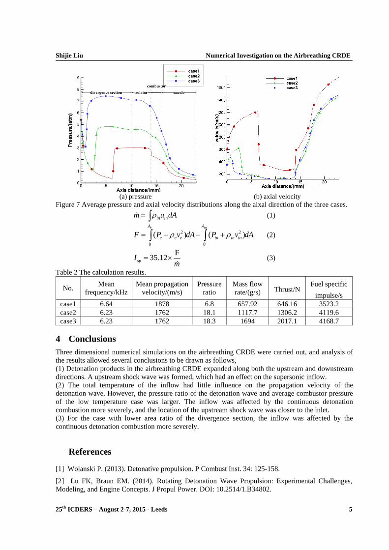
case2 case3 Figure 6 Time evolutions of the pressure and instantaneous frequency of Case2 and Case3. The flow field parameters were time averaged within six propagation cycles. Fig.7 shows the average pressure and axial velocity distributions along the aixal direction of the three cases. Based on the equations 1, 2 and 3, the mass flow rate, thrust and fuel specific impulse were calculated, and the results were shown in Table 2. The total temperature of case 2 was lower than that of case 1, so the mass flow rate of case 2 was larger, leading to a larger average combustor pressure. The inflow of case 2 was affected by the continuous detonation combustion more severely, and the location of the upstream shock wave was closer to the inlet. The inlet area of case 3 was larger than that of case 2, so the mass flow rate and average combustor pressure were larger than that of case 3. The inflow of case 3 was affected by the continuous detonation combustion more severely than that of case 2. Due to the higher combustor pressure, the fuel specific impusle of case 3 was the largest one.
Shijie Liu Numerical Investigation on the Airbreathing CRDE
25th ICDERS – August 2-7, 2015 - Leeds 5
(a) pressure (b) axial velocity Figure 7 Average pressure and axial velocity distributions along the aixal direction of the three cases.
in inm u dA (1)
2 2
0 0
( ) ( )e inA A
e e e in in inF P v dA P v dA (2)
F35.12spI
m
(3)
Table 2 The calculation results.
No. Mean
frequency/kHz Mean propagation
velocity/(m/s) Pressure
ratio Mass flow rate/(g/s) Thrust/N
Fuel specific
impulse/s
case1 6.64 1878 6.8 657.92 646.16 3523.2 case2 6.23 1762 18.1 1117.7 1306.2 4119.6 case3 6.23 1762 18.3 1694 2017.1 4168.7
4 Conclusions Three dimensional numerical simulations on the airbreathing CRDE were carried out, and analysis of the results allowed several conclusions to be drawn as follows, (1) Detonation products in the airbreathing CRDE expanded along both the upstream and downstream directions. A upstream shock wave was formed, which had an effect on the supersonic inflow. (2) The total temperature of the inflow had little influence on the propagation velocity of the detonation wave. However, the pressure ratio of the detonation wave and average combustor pressure of the low temperature case was larger. The inflow was affected by the continuous detonation combustion more severely, and the location of the upstream shock wave was closer to the inlet. (3) For the case with lower area ratio of the divergence section, the inflow was affected by the continuous detonation combustion more severely.
References
[1] Wolanski P. (2013). Detonative propulsion. P Combust Inst. 34: 125-158.
[2] Lu FK, Braun EM. (2014). Rotating Detonation Wave Propulsion: Experimental Challenges, Modeling, and Engine Concepts. J Propul Power. DOI: 10.2514/1.B34802.
Shijie Liu Numerical Investigation on the Airbreathing CRDE
25th ICDERS – August 2-7, 2015 - Leeds 6
[3] Braun EM, Lu FK, Wilson DR, Camberos JA. (2012). Airbreathing rotating detonation wave engine cycle analysis. Aerospace Science and Technology.
[4] Bykovskii FA, Vedernikov EF. (2003). Continuous detonation of a subsonic flow of a propellant. Combustion, Explosion, and Shock Waves 39(3): 323-334.
[5] Bykovskii FA, Zhdan SA, Vedernikov EF. Continuous detonation of syngas-air mixtures in an annular flow-type cylindrical combustor. 23 ICDERS, Taipei, Taiwan, July 28-August 2, 2013.
[6] Zhdan SA, Rybnikov AI. Numerical study of continuous spin detonation with a supersonic flow velocity. 23 ICDERS, Taipei, Taiwan, July 28-August 2, 2013.
[7] Hishida M, Fujiwara T, Wolanski P. (2009). Fundamentals of rotating detonations. Shock Waves, 19(1): 1-10.
[8] Fujiwara T, Hishida M, Kindracki J, Wolanski P. (2009). Stabilization of Detonation for Any Incoming Mach Numbers. Combustion, Explosion, and Shock Waves, 45(5): 603-605.
[9] Ye-tao Shao, Jian-ping Wang. (2010). Change in continuous detonation wave propagation mode from rotating detonation to standing detonation. Chinese Physics Letters 27(3): 034705.
[10] Schwer DA, Kailasanath K. (2012). Feedback into Mixture Plenums in Rotating Detonation Engines. AIAA 2012-0617.
[11] Schwer DA, Kailasanath K. (2013). On Reducing Feedback Pressure in Rotating Detonation Engines. AIAA 2013-1178.
[12] Liu SJ, Lin ZY, Sun MB, Liu WD. (2011). Thrust Vectoring of a Continuous Rotating Detonation Wave Engine by Changing the Local Injection Pressure. Chin. Phys. Lett. 28(9):094704.
[13] Liu SJ, Lin ZY, Liu WD, Lin W, Sun MB. (2013). Experimental and three-dimensional numerical investigations on H2/air continuous rotating detonation wave. Proc ImechE Part G J Aerosp Eng. 227(2):326-341.