Embed Size (px)
DESCRIPTION
IOSR Journal of Mechanical and Civil Engineering (IOSR-JMCE) vol.12 issue.2 version.3
Citation preview

IOSR Journal of Mechanical and Civil Engineering (IOSR-JMCE)
e-ISSN: 2278-1684,p-ISSN: 2320-334X, Volume 12, Issue 2 Ver. III (Mar - Apr. 2015), PP 51-55 www.iosrjournals.org
DOI: 10.9790/1684-12235155 www.iosrjournals.org 51 | Page
Numerical Investigation and Fatigue Life estimation of
Conventional Diesel Engine Piston
Dr. Hiregoudar Yerrennagoudaru1, Manjunatha K
2, Chandragowda M
3.
1A Professor and PG Co-ordinator (Thermal Power Engineering), Mechanical Engineering Department,
RYMEC Bellary, Karnataka, India 2ASST Professor and PROJECT Co-ordinator (Thermal Power Engineering), Mechanical Engineering
Department, RYMEC Bellary, Karnataka, India 3ASST Professor (Thermal Power Engineering), Mechanical Engineering Department, RYMEC Bellary,
Karnataka, India
Abstract: Nowadays engine components are subjected to higher load at elevated temperature than before, due
to the increase requirement regarding weight, performance and exhaust gas emission. Thus, Fatigue due to
simultaneous thermal and cyclic loading become determinant among the damage forms.
At the same time, there is the need to reduce development time and cost to handle the growing number of model
variant. Therefore, the development of suitable simulation tools, which reduces the number of necessary
component tests, seems to be very rewarding.
By using special material (aluminum alloy) we can reduce the fatigue load (Thermal and cyclic) on the piston
by using finite element analysis, ANSYS work bench 14.5 version.
I. Introduction Mechanical systems are frequently subjected to cyclic or random loading, inducing damages and
fatigue failure of many structural components. One of these structures, namely pressure vessels, is widely used
in many important branches of industry, such as power engineering, chemical engineering, and the
petrochemical industry.
IC engine, in general, are loaded by cyclic pulses and as a result stress concentration zones with plastic
strains may appear which induce initiation and propagation of fatigue cracks, leading to fatigue failure. Thus, it
is obligatory to estimate the fatigue limit and the fatigue life of pressure vessels to ensure safe service time for
these important expensive structures having far-reaching effects after their failure.
IC engine Piston are subjected to operating loading conditions which includes pressure, nozzle loads and thermal loads, resulting in the occurrence of stress concentration zones, initiation and propagation of fatigue
cracks. Approaches to fatigue life prediction are based on intensity stresses and strains. In the present
calculation, fatigue evaluation is carried out using stress based approach.
Approach and Assumptions:
ANSYS Meshing is used for meshing the component.
ANSYS 14.5 is used for solving and post-processing.
Material is assumed to be linear and isotropic.
Stress based approach is used for fatigue evaluation.
Fatigue life prediction is done as per ASME VIII DIV 2.
II. Methodology Geometries can be created top-down or bottom-up. Top-down refers to an approach where the
computational domain is created by performing logical operations on primitive shapes such as Piston crown,
Skirt of the Piston and Piston bowl. Bottom-up refers to an approach where one first creates vertices (points),
connects those to form edges (lines), connects the edges to create faces, and combines the faces to create
volumes. Geometries can be created using the same pre-processor software that is used to create the grid, or
created using other programs (e.g. CAD, UNI-GRAPHICS). Geometry files are imported into HM to create
computational domain.
Numerical Investigation and Fatigue Life estimation of Conventional Diesel Engine Piston
DOI: 10.9790/1684-12235155 www.iosrjournals.org 52 | Page
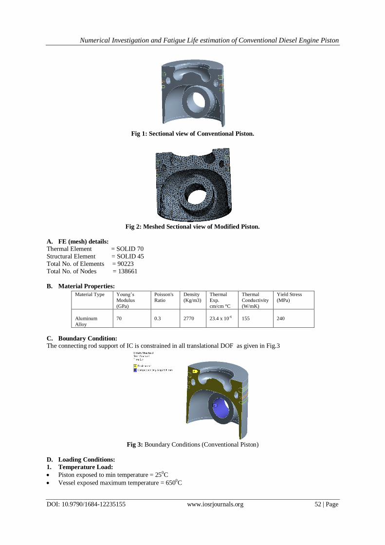
Fig 1: Sectional view of Conventional Piston.
Fig 2: Meshed Sectional view of Modified Piston.
A. FE (mesh) details:
Thermal Element = SOLID 70
Structural Element = SOLID 45
Total No. of Elements = 90223
Total No. of Nodes = 138661
B. Material Properties:
C. Boundary Condition:
The connecting rod support of IC is constrained in all translational DOF as given in Fig.3
Fig 3: Boundary Conditions (Conventional Piston)
D. Loading Conditions:
1. Temperature Load:
Piston exposed to min temperature = 250C
Vessel exposed maximum temperature = 6500C
Material Type
Young’s
Modulus
(GPa)
Poisson's
Ratio
Density
(Kg/m3)
Thermal
Exp.
cm/cm °C
Thermal
Conductivity
(W/mK)
Yield Stress
(MPa)
Aluminum
Alloy
70 0.3 2770
23.4 x 10⁻⁶
155 240

Numerical Investigation and Fatigue Life estimation of Conventional Diesel Engine Piston
DOI: 10.9790/1684-12235155 www.iosrjournals.org 53 | Page
2. Pressure Load:
Vessel exposed maximum Pressure = 60Bar
Vessel Exposed minimum pressure = 1 bar
III. Results And Discussion
Fig4: Temperature contour.
Fig5: Temperature contour.
Fig6: Displacement plot
Fig 7: Von-misses plot.

Numerical Investigation and Fatigue Life estimation of Conventional Diesel Engine Piston
DOI: 10.9790/1684-12235155 www.iosrjournals.org 54 | Page
Fig8: Shear stress plot.
IV. Damage Analysis: The damage analysis was performed with FEM (Finite element analysis) using transient temperature stress and
strain and time information from this analysis the concept of TMF analysis with FEM is displayed on the fig: 8.
The creep damage is not relevant for this component because it governed by thermal loading shows in fig: 7.
V. Conclusion: In this paper, it is shown how to evaluate the life of thermal and cyclic loaded components using FEM.
The method covers most of the effects and influences that operate under variable thermal and cyclic loading in
engine components. The life cycle calculation method includes the calculation of constants X,Y,Sa & N by
using following formulae.
Salt =Kf×Ke × ∆Sp,k
2= 277.54 Mpa
Kf= Fatigue Strength Reduction Factor = 2 for piston
Ke=Fatigue Penalty Factor = 1
∆Sp,k= 68.2Mpa
Cus = conversion factor.
Cus = 6.894757 for unit of stress in Mpa. Cusm = conversion factor =14.148299 for units of stress in Mpa.
EACS = modulus of elasticity of carbon steel at ambient temperature.
EFC = modulus of elasticity used to establish the design fatigue curve.
ET = modulus of elasticity of material under evaluation at the average temperature of the cycle being evaluated.
Y=10.13
X=5.92
N= 868587
Thermal stress analysis results shows 69.8 MPa stress at pressure vessel. Considering fatigue reduction
strength factor 2 art this stress range, the fatigue life of this vessel approximately 868587 Cycles.
References [1]. Back, T. – Schwefel, H-P.(1996): “Evaluation Computation: An Overview”, in proceedings of 196 IEEE International conference
on Evolutionary Computation, May 20-22,1996, Nagoya university, Japan. IEEE, pp.20-29.
[2]. Nelhiebel, A.(2005): Determination of the material parameters of a TMF damage model from experiments, Diplom thesis.
[3]. Price, K,-Storn, R. (1995): Differential Evolution – a simple and efficient adaptive scheme for global optimization over continuous
spaces. Technical Report TR-995-012, ICSI, March 1995
[4]. Sehitoglu, H, et al. (2002): “Thermomechanical fatigue analysis cast aluminum engine component”. Termomechnical fatigue
behavior of Material vol. 4, ASTM STP 1428

Numerical Investigation and Fatigue Life estimation of Conventional Diesel Engine Piston
DOI: 10.9790/1684-12235155 www.iosrjournals.org 55 | Page
[5]. Sehitoglu, H – Neu, R (1989): “Thermomechanical fatigue, Oxidation and creep: Part I and II. Experiments” Metallurgical
Transaction, 20A, pp. 1755-1767
[6]. J. Benajes.[1990] “Numerical solution of flow and combustion in an ax symmetric internal combustion engine”.
[7]. Semin, Rosli Abu Bakar and Abdul Rahim Ismail (2008) has studied” Computational Visualization and Simulation of Diesel
Engines Valve Lift Performance Using CFD”.
[8]. Gosman and Harvey has studied “Numerical solution of flow and combustion in an ax symmetric internal combustion engine”.
[9]. Y.Takenaka, M.Yabe, Y. Aoyagi and T. Shiozaki (1990) has studied “Three dimensional computation of In-cylinder Flow with
intake port in DI Diesel Engine”.
[10]. Benny Paul1 Flow field development in a direct injection diesel engine with different manifolds. International journal of
engineering, science and technology,Vol.2.No.1,2010.
[11]. F. Payri, J. Benajes, X. Margot, A. Gil, “CFD modeling of the in cylinder flow in direct-injection diesel engines,” Computers &
Fluids, vol. 33, pp. 995-1021, 2004.
[12]. Tippelmann G. Anew method of investigation of swirl ports. SAE 770404, 1977.
[13]. Uzkan T, Borgnakke C, Morel T. Characterization of flow produced by a high-swirl inlet port. SAE Paper 830266, 1983.
[14]. Versteeg HK, Malalasekera W. An introduction to computational fluid dynamics. The finite volume method. LongMan Scientific &
Technical; 1995.
[15]. Wakisaka T, Shimamoto Y, Issihiki Y. Three-dimensional numerical analysis of in-cylinder flows in reciprocating engines. SAE
860464, 1986.
[16]. Witze PO. Measurements of the spatial distribution and engine speed dependence of turbulent air motion in an IC engine. SAE
770220, 1977.
[17]. Woschni G. Auniversally applicable equation for the instantaneous heat transfer coefficient in the internal combustion engine. SAE
670931, 1967.
[18]. Yun J-E. New evaluation indices for bulk motion of in-cylinder flow trough intake port system in cylinder head. Proc IMechE, Part
D: J Automobile Eng 2002;216:513–21